

Page 1

ыэяью
Priport Controller
CPIF-26
Service Manual
Page 2

ø
ø
IMPORTANT SAFETY NOTICES
øø
PREVENTION OF PHYSICAL INJURY
1. Before disassembling or assembling parts of the printer and peripherals, make
sure that the power cord is unplugged.
2. The wall outlet should be near the controller and easily accessible.
3. If any adjustment or operation check has to be made with exterior covers off or
open while the main switch is turned on, keep hands away from electrified or
mechanically driven components.
OBSERVANCE OF ELECTRICAL SAFETY STANDARDS
The controller must be installed and maintained by a customer service
representative who has completed the training course on those models.
SAFETY AND ECOLOGICAL NOTES FOR DISPOSAL
Dispose of replaced parts in accordance with local regulations.
i
Page 3

General Remarks
The following table shows the conversion of the model names for each
manufacturer:
Model Code Company Model Name
C229
C231
C217
C225
C226
C224
C216
C211 Ricoh VT2100/VT2130/VT2150
Ricoh JP5000
Gestetner 5450
RexRotary 1560
Nashuatec CP450
Savin 3350DNP
Ricoh JP1010/1030/1045/1050
Gestetner 5306(L/b)/5000/5001
RexRotary 1224(B)
Nashuatec CP306(b)
Savin 3150DNP
Ricoh VT1730
Gestetner 5303
RexRotary 1220
Nashuatec CP303
Ricoh VT1800
Gestetner 5304
RexRotary 1222
Nashuatec CP304
Savin 3100DNP
Ricoh VT2250/VT2240
Gestetner 5329(L)
RexRotary 1254(L)
Nashuatec CP329(L)
Savin 3250DNP
Ricoh VT2200
Gestetner 5327
RexRotary 1252
Nashuatec CP327
Savin 3200DNP
Ricoh VT2105
Gestetner 5325
RexRotary 1250
Nashuatec CP325
Gestetner 5310/5315/5320
RexRotary 1240/1241/1242
Nashuatec CP310/CP315
ii
Page 4

Model Code Company Model Name
C212
Ricoh VT2300
Gestetner 5330
RexRotary 1260
Nashuatec CP330
C210
Ricoh VT3500
Gestetner 5375
RexRotary 1280
Nashuatec CP375
C218
Ricoh VT3600
Gestetner 5380
RexRotary 1285
Nashuatec CP380
C223
Ricoh VT3800
Gestetner 5385
RexRotary 1290
Nashuatec CP385
Savin 3300DNP
C219
Ricoh VT2600/VT2630
Gestetner 5360
RexRotary 1270
Nashuatec CP360
C222
Ricoh VT2400
Gestetner 5340
RexRotary 1255
Nashuatec CP340
C228
Ricoh VT6000
Gestetner 5390
RexRotary 1295
Nashuatec CP390
Savin 3400DNP
C214
Gestetner 5305/5330
RexRotary 1230
Nashuatec CP305
iii
Page 5

Contents
1. OVERALL INFORMATION............................................................. 1
1.1 HOST SYSTEMS.........................................................................................1
1.2 BASIC SPECIFICATION..............................................................................1
1.3 RESIDENT FONT LIST................................................................................2
1.4 VIDEO INTERFACE KITS............................................................................5
2. BASIC FUNCTION......................................................................... 7
2.1 BASIC CONFIGURATION ...........................................................................7
2.2 SPECIFICATIONS AND CONFIGURATIONS OF I/O PORTS ....................9
3. VIDEO I/F INSTALLATION PROCEDURES ................................ 13
3.1 VIDEO I/F KIT TYPE-600 PARTS LIST .....................................................13
3.2 VIDEO I/F KIT TYPE-10 PARTS LIST.......................................................14
3.3 INSTALLATION PROCEDURES FOR INTERFACE KITS.........................15
4. OPERATION VERIFICATION....................................................... 27
4.1 TOOLS.......................................................................................................27
4.2 TESTS........................................................................................................28
5. TROUBLESHOOTING ................................................................. 31
5.1 BASIC STEPS FOR TROUBLESHOOTING..............................................31
5.2 TROUBLESHOOTING FLOW....................................................................33
5.3 PRIPORT/CONTROLLER FAILURE IDENTIFICATION............................34
5.4 SUBASSEMBLY TROUBLESHOOTING....................................................35
5.5 NIB FIRMWARE AND MEMORY UPGRADE TROUBLESHOOTING .......36
5.6 LED STATUS LIGHT SEQUENCE AND CONDITIONS ............................37
5.7 DIAGNOSTIC TEST PAGE CONTENTS...................................................43
5.8 CHECKING PRINTER DRIVER OPERATION...........................................44
5.9 COLLECTING INFORMATION FOR A PROBLEM REPORT....................45
6. DISASSEMBLY / ASSEMBLY..................................................... 47
6.1 REQUIRED TOOLS AND PRECAUTIONS................................................47
6.2 DISASSEMBLY PROCEDURES................................................................48
6.3 ASSEMBLY PROCEDURES ......................................................................53
6.4 UPGRADING CONT ROLLER FIRMWARE................................................56
6.5 UPGRADING CONTROLLER RAM...........................................................70
7. PARTS LIST................................................................................. 83
7.1 CPIF-26......................................................................................................83
7.2 PC CONTROLLER I/F KIT TYPE-600 .......................................................85
7.3 PC CONTROLLER I/F KIT TYPE-10 .........................................................87
Page 6

30 April 1999 HOST SYSTEMS
1. OVERALL INFORMATION
1.1 HOST SYSTEMS
Priport Controller CPIF-26 is external box type raster image processor for
PRIPORTs. By connecting the controller with PRIPORT, the computer data will be
printed in as well as printing from PRIPORT’s scanner. The following are the target
computer hosts for this controller.
Target Host Computer Systems
• IBM PC/AT compatible PC with Windows 95 with Internet Explorer 4.01 SP1,
Windows 98, or Windows NT4.0 with SP3 operating systems.
• Apple Macintosh with MAC OS 7.6.1, or later.
There are no minimum system hardware requirements, other than those imposed
by the operating systems.
1.2 BASIC SPECIFICATION
Contents Description
Configuration External Box Type Controller Un it
Priport Models JP5000, JP1010, JP1030, JP1045, JP1050, and
VT6000
Overall
Information
I/O Interfaces Host
• Parallel I/F (ECP Bi-directional Centronics)
• LocalTalk (RS422)
• 10 BaseT (RJ45) Ethernet/EtherTalk
Video
• RSVI Interface
Page Description Language
Image Resolution 300 dpi, 400 dpi, 600 dpi
RAM Standard:32MB, Maximum: 256MB
Paper Size A3,A4,B4, B5,
Resident Fonts
PostScript3 Level 3
PCL-5e (HP LaserJet 4si compatible)
(72-pin 60ns EDO SIMM, non-parity, at 5 volts
with 2K maximum refresh rate)
• See Section 6.5 for more explanation.
US Letter, US Legal, US Tabloid
• See section 1.3 Resident Font List.
Table 1.2. Basic Controller Specifications.
1
Page 7

RESIDENT FONT LIST 30 April, 1999
1.3 RESIDENT FONT LIST
1.3.1 PS3 FONTS
Albertus ‡
Albertus Italic ‡ Courier
Albertus Light ‡ Courier Bold
AntiqueOlive Bold § Courier Bold Oblique
AntiqueOlive Compact § Courier Oblique
AntiqueOlive Italic § Eurostile **
AntiqueOlive Roman § Eurostile Bold **
Apple Chancery ˜ Eurostile Bold Extended Two **
Arial ‡ Eurostile Extended Two **
Arial Bold Italic ‡ Geneva
Arial Bold ‡ GillSans ‡
Arial Italic ‡ GillSans Bold ‡
ITC AvanteGarde Gothic Book ° GillSans Condensed Bold ‡
ITC AvanteGarde Gothic Book Oblique ° GillSans Bold Italic ‡
AvanteGarde Gothic Demi ° GillSans Condensed ‡
AvanteGarde Gothic Demi Oblique ° GillSans Extra Bold ‡
Bodoni GillSans Italic ‡
Bodoni Bold GillSans Light ‡
Bodoni Bold Italic GillSans Light Italic ‡
Bodoni Italic Goudy
Bodoni Poster Goudy Bold
Bodoni Poster Compressed Goudy Bold Italic
ITC Bookman Demi ° Goudy ExtraBold
ITC Bookman Demi Italic ° Goudy Oldstyle Italic
ITC Bookman Light ° Helvetica ✝
ITC Bookman Light Italic ° Helvetica Bold ✝
Carta •
Chicago ˜ Helvetica Condensed ✝
Clarendon ✝ Helvetica Condensed Bold ✝
Clarendon Bold ✝ Helvetica Condensed Bold Oblique ✝
Clarendon Light ✝ Helvetica Condensed Oblique ✝
CooperBlack Helvetica Narrow ✝
CooperBlack Italic Helvetica Narrow Bold ✝
Copperplate ThirtyThree Helvetica Narrow Bold Oblique ✝
Copperplate ThirtyTwo Helvetica Narrow Oblique ✝
Coronet Regular ••
Helvetica Bold Oblique ✝
2
Page 8

30 April 1999 RESIDENT FONT LIST
Helvetica Oblique ✝ Palatino Italic ✝
Hoefler Text Black ˜ Palatino Roman ✝
Hoefler Text Black Italic ˜ Stempel Garamond Bold ✝
Hoefler Text Italic ˜ Stempel Garamond Bold Italic ✝
Hoefler Text Ornaments ˜ Stempel Garamond Italic ✝
Hoefler Text ˜ Stempel Garamond Roman ✝
Joanna ‡ ITC Symbol °
Joanna Bold ‡
Tekton •
Joanna Bold Italic ‡ Times Bold ✝
Joanna Italic ‡ Times Bold Italic ✝
LetterGothic Times Italic ✝
LetterGothic Bold Times Roma n ✝
LetterGothic Bold Slanted Times New Roman Bold ‡
LetterGothic Slanted Times New Roman Bold Italic ‡
ITC Lubalin Graph Book ° Times New Roman Italic ‡
ITC Lubalin Graph Book Oblique ° Times New Roman ‡
ITC Lubalin Graph Demi ° Universe ✝
ITC Lubalin Graph Demi Oblique ° Universe Bold ✝
Marigold * Universe Bold Oblique ✝
ITC Mona Lisa Recut ° Universe Oblique ✝
Monaco ˜ Universe Light ✝
New Century Schoolbook Bold ✝ Universe Light Oblique ✝
New Century Schoolbook Bold Italic ✝ UniverseCondensed ✝
New Century Schoolbook Italic ✝ UniverseCondensed Bold ✝
New Century Schoolbook Roman ✝ UniverseCondensed Bold Oblique ✝
New York ˜ UniverseCondensed Oblique ✝
Optima ✝ UniverseExtended ✝
Optima Bold ✝ UniverseExtended Bold ✝
Optima Bold Italic ✝ UniverseExtended Bold Oblique ✝
Optima Italic ✝ UniverseExtended Oblique ✝
Oxford * Wingdings Regular °°
Palatino Bold ✝ ITC ZapfChancery Medium Italic °
Palatino Bold Italic ✝
ITC ZapfDingbats °
Overall
Information
Registered trademark of Adobe Incorporated, ∗∗ Trademark of Nebiolo,
•
✝
Registered trademark of International Typeface Corporation,
°
Hell AG and/or its subsidiaries, § Registered trademark of Marcel Olive,
Trademark of Alpha Omega Typography, ˜ Trademark of Apple Computer Inc.,
∗
Registered trademark of Ludlow type Foundry, °° Trademark of Microsoft Corporation, ‡
••
Trademark of Monotype Corporation
3
Trademark of Linotype-
#
Page 9

RESIDENT FONT LIST 30 April, 1999
1.3.2 PCL FONTS
Scalable Fonts: 35 Intellifont fonts
Albertus, Albertus Extrabold, Antique Olive, Antique Olive Italic, Antique Olive Bold,
Clarendon Condensed, Coronet, Courier, Courier Italic, Courier Bold, Courier Bold
Italic, Garmond Antiqua, Garamond Kursiv, Garamond Halbfett, Garamond Kursiv
Halbfett, Letter Gothic, Letter Gothic Italic, Letter Gothic Bold, Marigold, CG
Omega, CG Omega Italic, CG Omega Bold, CG Omega Bold Italic, CG Times, CG
Times Italic, CG Times Bold, CG Times Bold Italic, Univers Medium, Univers
Medium Italic, Univers Bold, Univers Bold Italic, Univers Medium Condensed,
Univers Medium Condensed Italic, Univers Bold Condensed, Univers Bold
Condensed Italic
Scalable Fonts: 10 TrueType fonts
Arial, Arial Italic, Arial Bold, Arial Bold Italic, Times New Roman, Times New
Roman Italic, Times New Roman Bold, Times New Roman Bold Italic, Wingdings
Fixed Pitch Fonts: 1 Intellifont font
Line Printer (8.5 pt 16.67 pitch)
4
Page 10

30 April 1999 VIDEO INTERFACE KITS
1.4 VIDEO INTERFACE KITS
Description Contents
PC Controller I/F Kit Type-600 For the connection to VT6000
PC Controller I/F Kit Type-10 For the connection to JP1010,
JP1030, JP1045, JP1050, and
JP5000 (Asian version only)
* The interface kit is originally installed
for JP5000, except for the Asian
version machines.
Table 1.4. Interface Kits for use with the Controller.
Overall
Information
5
Page 11
30 April, 1999 BASIC CONFIGURATION
(
)
2. BASIC FUNCTION
2.1 BASIC CONFIGURATION
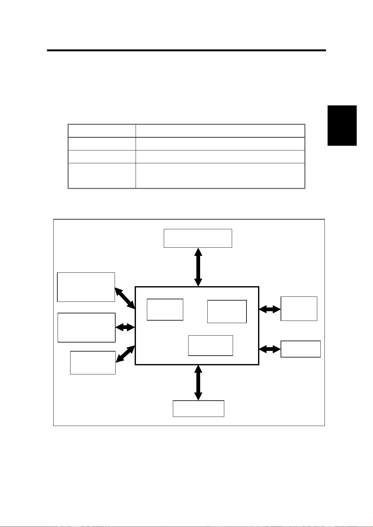
2.1.1 MAIN BOARD SPECIFICATIONS AND BLOCK DIAGRAM
Main Printed Circuit Board specifications are listed in the table below.
Description CPIF 26 Controller
CPU NEC VR4300 100MHz
DRAM 32MB (SIMM)
Flash ROM 8Mb on Main Board,
Block Diagram
Local Talk
(RS422)
Centronics I/F
1Mb Flash ROM SIMM (subject to change)
Table 2.1. Main Board Specifications.
CPU: VR4300
CPLD
Flash
ROM
ROM
SIMM
Basic
Function
(IEEE-1284)
10 Base T
RJ45
FPGA
Memory
Video I/F
Figure 2.1. Controller Block Diagram.
7
Page 12

BASIC CONFIGURATION 30 April, 1999
2.1.2 MAIN BOARD LAYOUT
RAM SIMM Slot 1
LED's
Power
Connector
– J12
Network I/F (NIB)
Connector – J8
26-pin Optional Printer
Port Connector – J9
Console Connector
Serial Port Header – JP2
RAM SIMM Slot 2
Flash ROM SIMM Slot
Duplicator Video I/F
Header – J2
Switch 1 – SW1
(4-pin switch)
Test Button
Parallel
AppleTalk
Figure 2.1.2. Main Board Layout
8
Page 13
30 April, 1999 SPECIFICATIONS AND CONFIGURATIONS OF I/O PORTS
2.2 SPECIFICATIONS AND CONFIGURATIONS OF I/O
PORTS
The CPIF 26 Controller supports connection to a computer for printing
from any of the following ports:
Parallel Port (IEEE 1284, ECP Bi-directional)
LocalTalk (Apple computers)
10-BaseT LAN Port
• Ethernet for IBM-compatible PCs (IPX and IP protocols)
• EtherTalk for Apple Macintosh PCs (AppleTalk and IP protocols)
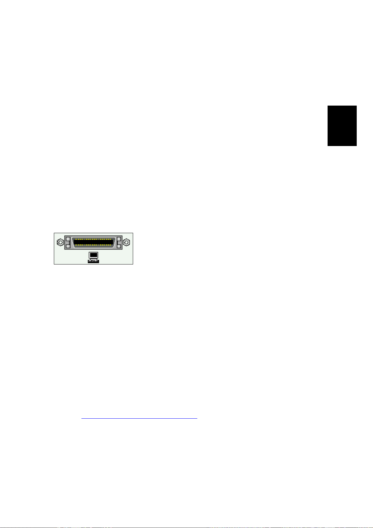
2.2.1 PARALLEL MINI-CENTRONICS INPUT PORT
2.2.1.1 Description
The high-performance parallel input/output port on
the controller utilizes the
supporting hardware-enhanced, nibble-mode reversedirection data transfer, for high-speed communication
between the computer and controller. Be sure to use
a cable conforming to this design standard to realize the full data speed
benefit from this interface.
2.2.1.2 IEEE 1284 Parallel Port Characteristics
IEEE 1284 – 1994
design,
Basic
Function
Maximum data speed: 2 MBytes/sec.
Maximum cable length: 10 meters (30 feet).
Chassis connector type: IEEE 1284 Type C (Mini-Centronics).
Design standard: IEEE 1284 – 1994.
To use this interface, the parallel port (e.g., LPT1:) on the user’s
computer must be configured as an
For more information on the parallel port, point your Internet web
browser to:
http://www.fapo.com/ieee1284.htm
ECP
(not EPP)
9
Printer Port
.
Page 14

SPECIFICATIONS AND CONFIGURATIONS OF I/O PORTS 30 April, 1999
2.2.1.3 IEEE 1284 Parallel Port Pinout
Computer End Controller End
1284A Connector Pin
1 nStrobe 15
18 Rtn 33
2 Data_1 6
19 Rtn 24
3 Data_2 7
19 Rtn 25
4 Data_3 8
20 Rtn 26
5 Data_4 9
20 Rtn 27
6 Data_5 10
21 Rtn 28
7 Data_6 11
2 Rtn 29
8 Data_7 12
22 Rtn 30
9 Data_8 13
22 Rtn 31
10 nAck 3
24 Rtn 21
11 Busy 1
23 Rtn 19
12 PE 5
24 Rtn 23
13 Select 2
24 Rtn 20
14 nAutoFeed 17
25 Rtn 35
15 nFault 4
23 Rtn 22
16 nInit 14
25 Rtn 32
17 nSelectIn 16
25 Rtn 34
(nc) +5V/Host_Avail 18
(nc) Perph_Avail 36
Signal
1284C Connector Pin
Table 2.2.1.3. IEEE 1284 A-to-C Connector Contact Numbering
10
Page 15
30 April, 1999 SPECIFICATIONS AND CONFIGURATIONS OF I/O PORTS
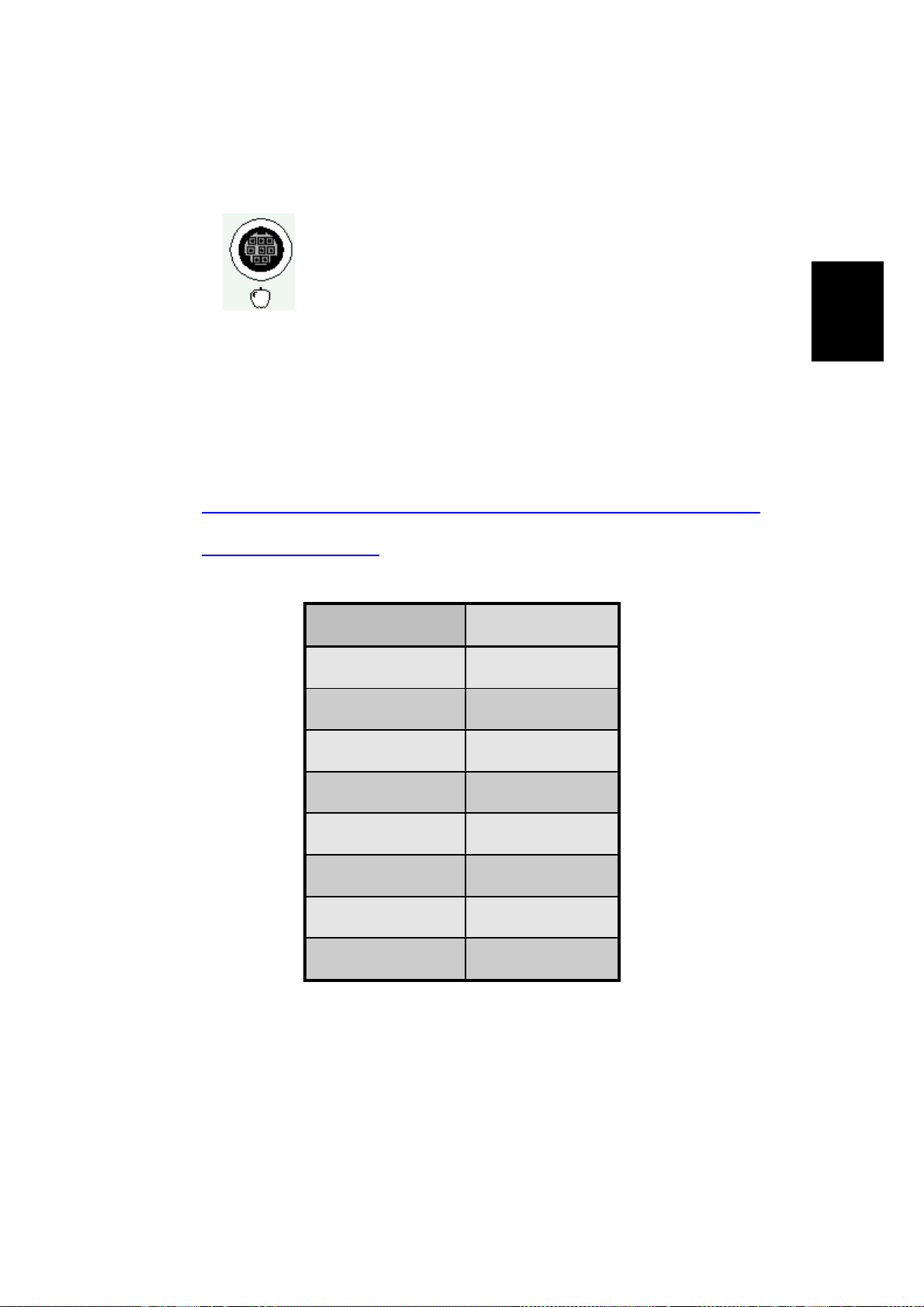
2.2.2 LOCALTALK CONNECTION
2.2.2.1 Description
The LocalTalk interface is used by the Macintosh series
of computers designed and built by Apple Computer, Inc.
It is a bi-directional port and supports the AppleTalk local
area network (LAN) protocol.
2.2.2.2 LocalTalk Port Characteristics
Maximum data speed: 230.4Kbs / 28.8KBytes/sec.
Maximum cable length: 300 meters (1000 feet).
Chassis connector type: 8-pin mini-DIN female.
Design standard: Apple proprietary.
For more information on AppleTalk and LocalTalk, point your Internet
web browser to:
http://www.cisco.com/univercd/cc/td/doc/cisintwk/ito_doc/55142.htm
http://www.apple.com
2.2.2.3 LocalT alk Port Pinout
Contact Number Signal Name
1 (not connected)
2 (not connected)
3 - Data Out
- or -
Basic
Function
4 Ground
5 - Data In
6 + Data Out
7 (not connected)
8 + Data In
Table 2.2.2.3. LocalTalk Connector Contact Numbering.
11
Page 16

30 April, 1999 VIDEO I/F KIT TYPE-600 PARTS LIST
3. VIDEO I/F INSTALLATION PROCEDURES
3.1 VIDEO I/F KIT TYPE-600 PARTS LIST
3.1.1 COMMON ASSEMBLIES
No. Description Qty.
1 IC – Interface 1
2 Interface Board 1
3 Insulating sheet – 145 x 200 1
4 Interface Cable – Interface Board 1
Table 3.1.1. Common Assemblies.
3.1.2 SET FOR PART 1A
No. Description Qty.
5 Stud – 50mm 2
6 Spacer – 10mm 2
7 PCB Stud – 64mm 2
8 Harness Support Bracket 1
9 Philips Pan Head Screw – M3 x 35 1
10 Philips Flange Screw – M3 x 8 3
11 Philips Flange Screw – M4 x 8 3
12 Flat Cable – N810/NA33/NA3/NB2/RN925/N850 1
13 Wire Band 1
14 PCB Collar 1
Table 3.1.2. Set for Part 1A.
3.1.3 SET FOR PART 1B
No. Description Qty.
15 Flat Cable – NA2 1
16 Main Board Spacer 1
17 Stud – Bracket – Interface 2
18 Interface Board Bracket 1
19 Philips Screw with Flat Washer – M3 x 25 1
20 Stud – Main Board 1
21 Philips Screw with Flat Washer – M4 x 6 1
22 Philips Screw – M4 x 8 2
23 Philips Screw with Flat Washer – M3 x 6 2
Installation
Table 3.1.3. Set for Part 1B.
13
Page 17

VIDEO I/F KIT TYPE-10 PARTS LIST 30 April, 1999
3.1.4 SET FOR PART 1C
No. Description Qty.
24 Interface Board Stud 2
25 Main Board Stud – Long 4
26 Philips Screw – M4 x 8 2
27 Philips Screw with Flat Washer – M3 x 6 4
28 Flat Cable – N865 1
Table 3.1.4. Set for Part 1C.
3.1.5 PARTS FOR 1D
No. Description Qty.
29 Stud – 35mm 3
30 Philips Screw with flat Washer – M3 x 6 3
31 Philips Screw – M4 x 8 2
Table 3.1.5. Set for Part 1D.
3.2 VIDEO I/F KIT TYPE-10 PARTS LIST
No. Description Qty.
32 Interface Board 1
33 Relay Harness 1
34 Stepped Screw – M2.6 2
35 Tapping Screw – M3 x 6 2
Table 3.2.1. Video I/F kit Type-10.
14
Page 18
30 April, 1999 INSTALLATION PROCEDURES FOR INTERFACE KITS
3.3 INSTALLATION PROCEDURES FOR INTERFACE KITS
NOTE:
1) The CPIF26 Controller is designed for the JP1010/1030/1045/1050,
JP5000, and VT6000 models only. The installation procedures for the
other models are just for reference for the other controllers.
2) Numbers in parentheses ( ) in the installation procedures correspond to
the part numbers in Tables 3.1 through 3.2.
3.3.1 JP5000
NOTE:
The interface kit is originally installed for the JP5000, except for the Asian
version machines. You must perform step 3 only to connect the controller if
the kit is installed.
1. Remove the rear cover and right side
panel of the Priport.
2. Mount Printed Circuit Board (32) on
connector CN102 of the MPU board
using two M3x6 screws (35). Mount
the cable (33) on the Connector
Bracket using two stepped screws
(34).
CN102
Installation
Printed
Circuit
Board
3. Remove the blinding cover in the right
side panel.
NOTE:
If SP Mode 2-6 (PC Controller
Settings) is set at “AUTO” (i.e. the
default setting), the On-line key is
enabled automatically when the
controller and interface kit are
installed.
Harness
Connector Bracket
Blinding Cover
15
Page 19
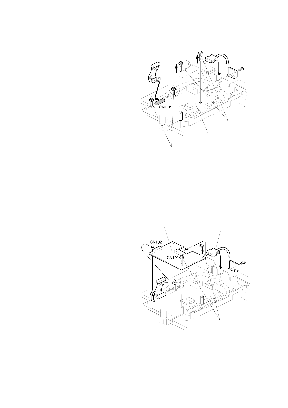
INSTALLATION PROCEDURES FOR INTERFACE KITS 30 April, 1999
3.3.2 JP1010/1030/1045/1050
Harness
Printed Circuit Board
MPU
Connector Bracket
1. Turn off the main switch and unplug the power cord.
2. Remove the upper rear cover.
3. Remove the MPU cover.
4. Connect CN102 of the printed circuit board (32) to CN110 of the MPU board
and secure it using two screws (35).
5. Connect the harness (33) to CN101 of the printed circuit Board, and secure it to
the connector bracket using two stepped screws (34).
6. Remove the communications port cover plate (blinding cover) from the upper
rear cover.
7. Reinstall the MPU cover.
8. Reinstall the upper rear cover.
NOTE:
The On-line key on the operation panel is enabled automatically when the
controller and interface kit are installed.
16
Page 20
30 April, 1999 INSTALLATION PROCEDURES FOR INTERFACE KITS
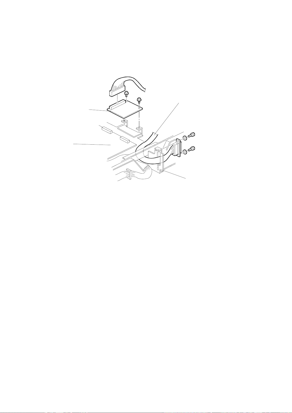
3.3.3 VT6000/3800/3600/3500/2600
1. Remove the rear cover and front side panel of the Priport.
2. Mount the Shielded Cable Interface (2).
a) Mount a Stud (17) on the rear chassis of the Priport.
b) Thread the Shielded Cable (4) from rear chassis to the front chassis
under the Priport body.
Note for the VT3600/3500/2600: first remove the bottom plate, then reattach it.
c) Attach the Shielded Cable (4) on the Stud (17) using two M4x8 Screws
(26).
NOTE:
Before mounting Printed Circuit Board Interface (2), attach one end of the
Ribbon Cable (12) to the IPU board ribbon cable connector.
Installation
3. Mount the Printed Circuit Board
Interface (2).
a) Mount a Stud (20) on the
Priport.
b) Mount the Bracket (18) on the
chassis using a M4x6 screw
and washer (21).
c) Attach the Printed Circuit Board
(2) using 2, M3x6 screws (27).
Attach the bottom of the right
hand side of the Printed Circuit
Board to the Spacer (16) using
a M3x25 screw (19).
d) Attach the connector of the
Printed Circuit Board (2) to the
Shielded Cable (4).
e) Attach free end of the Ribbon
Cable (21) to the Printed Circuit
f) Board Interface (2).
M4x6 Screw
Interface Board
M3x6 Screws
Stud
Bracket
M3x25 Screw
IPU board
Spacer
Ribbon
Cable
17
Page 21
INSTALLATION PROCEDURES FOR INTERFACE KITS 30 April, 1999
4. Set the Printed Circuit Board interface switches.
a) Set all switches on DIPSW 101 to OFF.
5. Re-attach the side cover panels
of the Priport.
a) Pop out the communication
port cover plate from the
lower center of the rear
cover panel.
b) Reinstall the rear and front
cover panels.
6. Connect the Priport and AC power to the Controller.
a) Connect a Video Cable between the Priport and the Controller.
b) Connect an AC cable to the Controller.
7. Set SP Mode 1 (for the Online Key On/Off) to ON.
Communication port cover
18
Page 22
30 April, 1999 INSTALLATION PROCEDURES FOR INTERFACE KITS
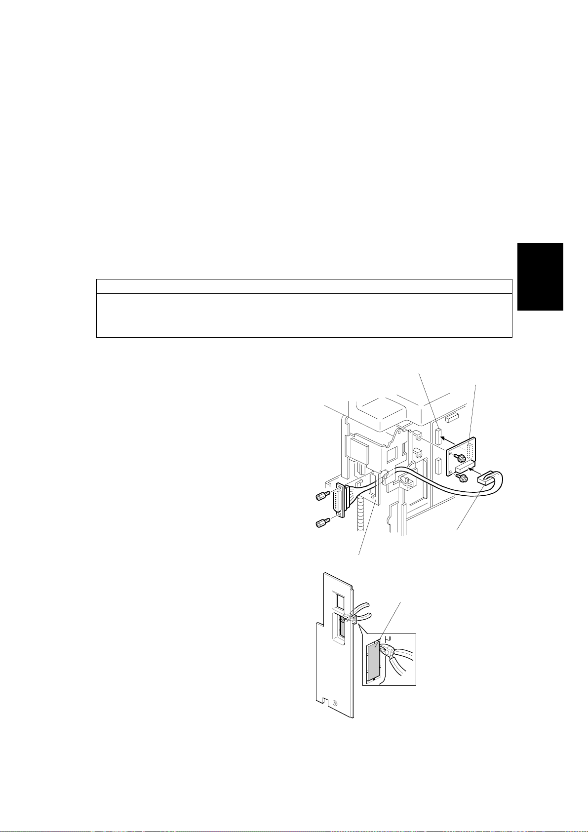
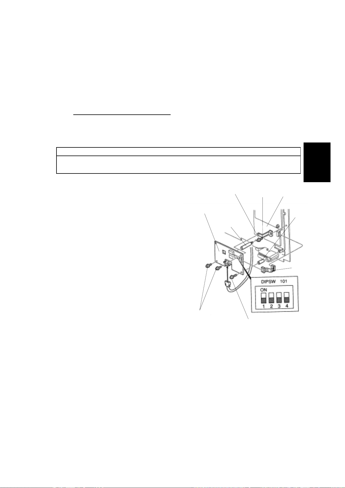
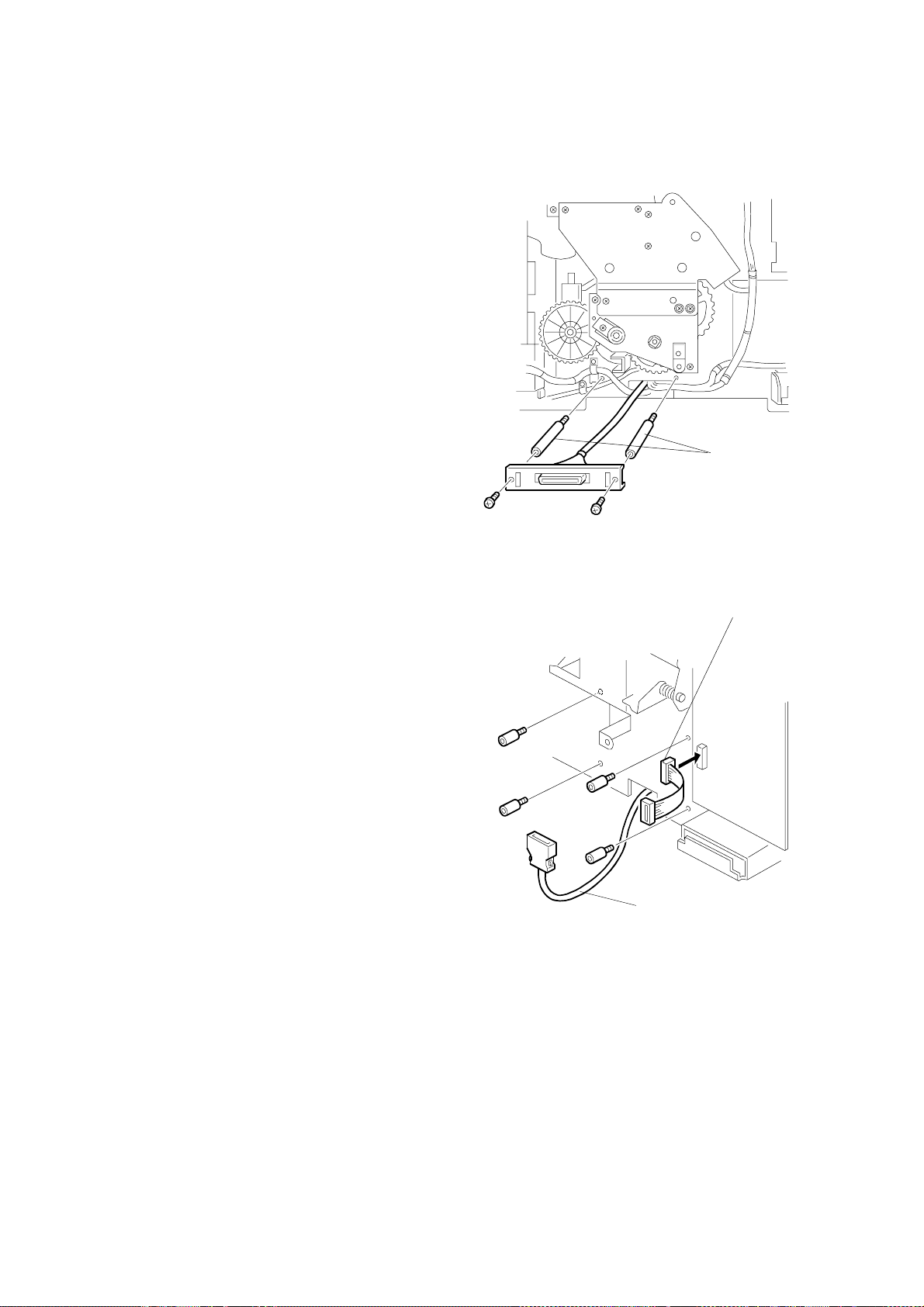
3.3.4 VT2400
1. Remove the rear cover and front side
panel of the Priport.
2. Mount Shielded Cable Interface (4).
3. Mount Printed Circuit Board Interface
(2).
a) Remove the three screws
attaching t he mainframe MPU
Board to the chassis (two
screws upper and lower side of
CN109, and one screw lower
side of the CN111).
b) Replace the screws removed in
a) above with Studs (29).
c) Connect one side of the Ribbon
Cable (12) to the connector of
Mainframe MPU Board.
d) Attach the Printed Circuit Board
Interface (2) to the Studs (29)
using M3x6 Screws (27).
e) Connect the free end of the
Ribbon Cable (12) to the CN102
connector of Printed Circuit
Board Interface (2).
f) Set all switches of DIPSW 101
on the Printed Circuit Board
Interface (2) to OFF.
Shielded Cable
Studs
Installation
4. Pop out the communication port cover
plate from the lower center of the rear
cover panel. Reinstall the rear and
front cover panels.
5. Set SP Mode 2-1 (Online Key On/Off)
to ON.
Printed Circuit Board Interface
19
Page 23
INSTALLATION PROCEDURES FOR INTERFACE KITS 30 April, 1999
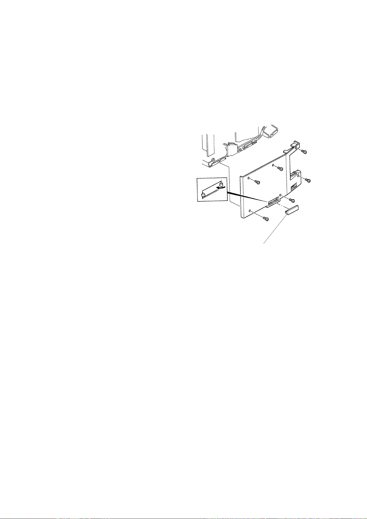
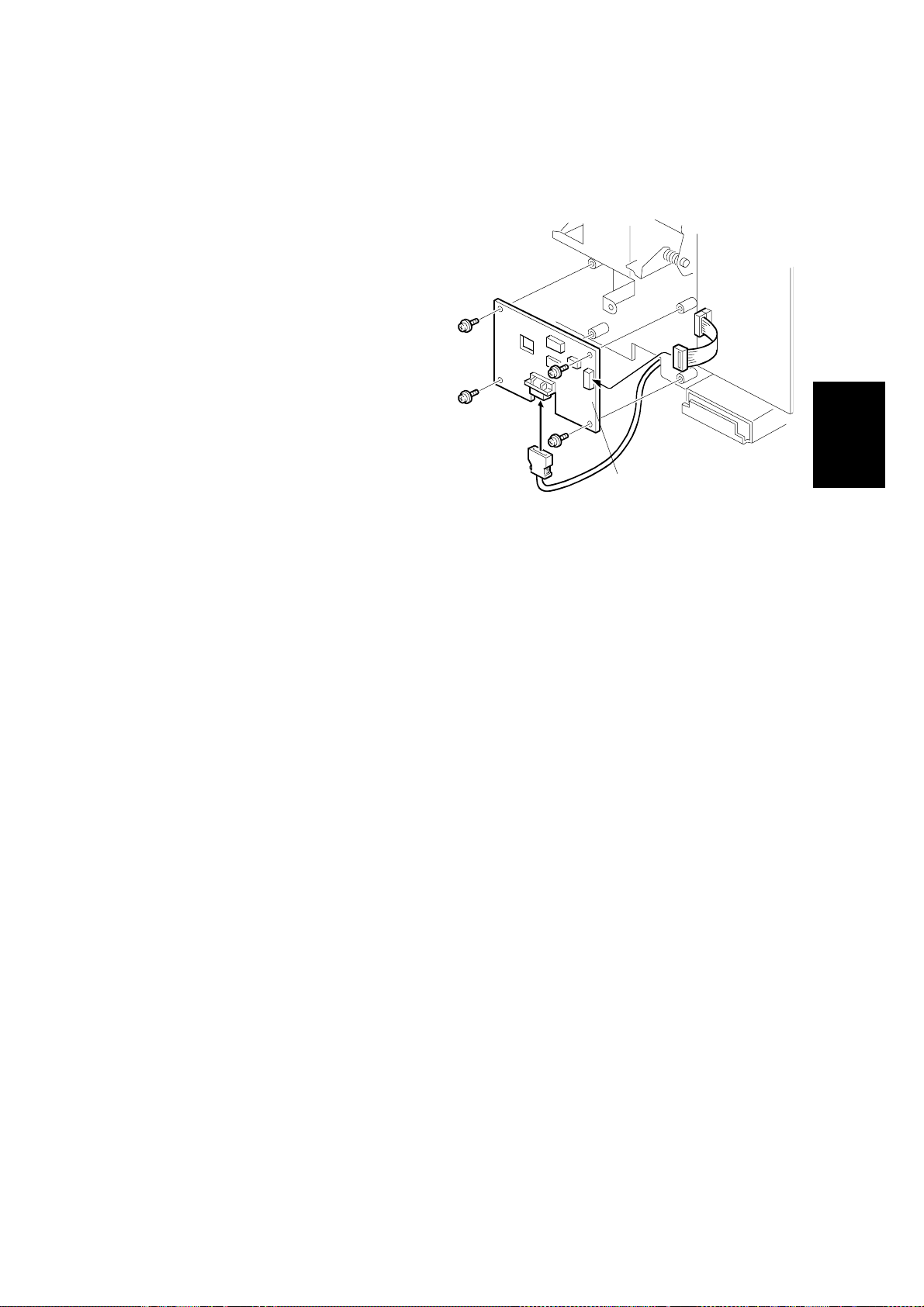
3.3.5 VT2240/VT2250
1. Remove the top cover of the
Mainframe MPU Board.
2. Remove screws attached to the
two studs on the top of MPU
Control Board.
3. Connect the free end of the
Ribbon Cable (12) to the
connector marked CN110
located at the left edge of the
MPU Control Board.
4. Position the MPU Control Board
and Printed Circuit Board
Interface (2) on the Studs.
5. Attach the Printed Circuit Board
Interface (2) to the MPU Control
Board, taking care to align the
left edge with the locking
spacers.
MPU Control Boar d
Locking Spacers
Screw
6. Attach the right side edge of the
Printed Circuit Board (2) to the
mounting Studs on the MPU
Control Board using three M3x6
screws.
7. Connect the free end of the
Ribbon Cable (12) to the
connector marked CN102 on the
Printed Circuit Board Interface
(2).
8. Attach the Shielded Cable to the
Printed Circuit Board Interface
(2).
Printed Circuit
Board Interface
Shielded Cable
Screws M3x6
20
Page 24
30 April, 1999 INSTALLATION PROCEDURES FOR INTERFACE KITS
9. Remove the rear cover panel of the Priport.
10. Remove the Plate attached to the channel for the Main Harness in the rear
upper of the Chassis.
11. Route the Shielded Cable (4)
along side the Main Harness.
12. Re-attach the Plate.
13. Mount the Studs (24) on the rear
chassis of the Priport.
14. Mount the Bracket end of the
Shielded Cable (4) onto the
Studs (24) using two M4x8
screws (26).
15. Tie the Shielded Cable (4) to
Main Harness using the Tie Band
(13).
16. Pop out the communication port
cover plate from the lower center
of the rear cover panel.
17. Reinstall the rear cover panel of
the Priport.
18. Set all switches on DIPSW 101 of
the Printed Circuit Board Interface (2) to OFF.
Plate
Tie Band
Installation
Studs
Bracket
19. Re-install the top cover of the Priport.
20. Set SP Mode 1 (Online Key On/Off) to ON.
21
Page 25
INSTALLATION PROCEDURES FOR INTERFACE KITS 30 April, 1999
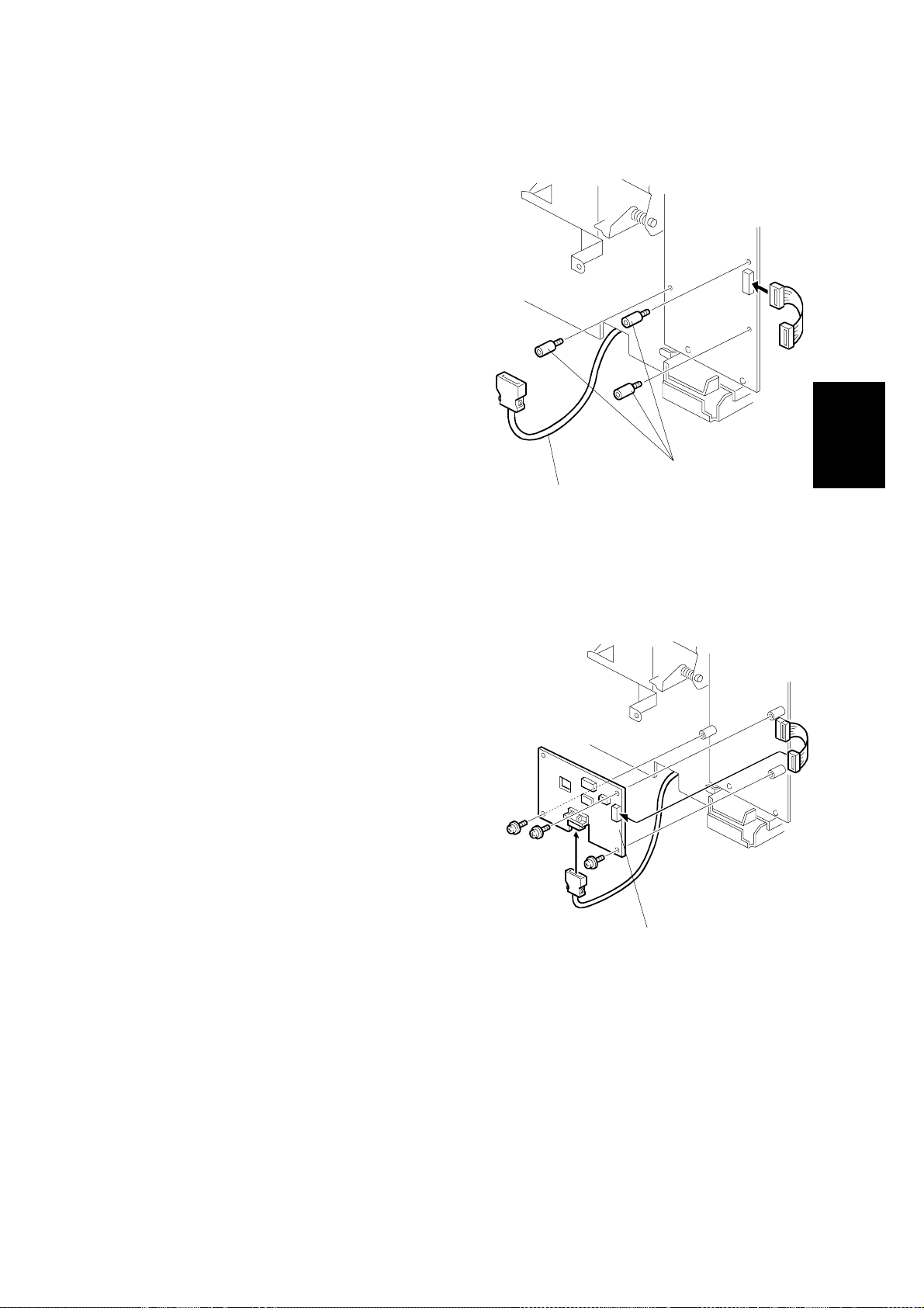
3.3.6 VT2200
1. Remove the rear and front covers
of the Priport.
2. Mount Shielded Cable Interface (4).
a) Mount two Studs (24) on the rear
chassis of the Priport.
b) Remove bottom plate of the
Priport.
c) Thread the Shielded Cable (4)
from the rear chassis to the front
chassis under the Priport body.
d) Reinstall the bottom plate.
e) Mount the Bracket of the
Shielded Cable (4) on the Studs
(8) using two Phillips Screws
M4x8 (26).
Stud
3. Mount Printed Circuit Board
Interface (2).
a) Mount four Studs (25) on the
front chassis of the Priport.
b) Connect the Ribbon Cable (12)
to the MPU board of the Priport.
Flat Cable
Shield Cable
22
Page 26
30 April, 1999 INSTALLATION PROCEDURES FOR INTERFACE KITS
c) Attach the Printed Circuit
Board Interface (2) to the
Studs (25) using four M3x25
Screws (20).
d) Connect the free end of the
Ribbon Cable (27) to CN102
of the Printed Circuit Board
Interface (2).
e) Connect the Shielded Cable
(4) to CN101 of the Printed
Circuit Board Interface (2).
f) Set a ll switches on DIPSW
101 of the Printed Circuit
Printed Circuit Board
Board Interface (2) to OFF.
g) Set DIPSW 103-8 of the
Mainframe MPU Board
(Online On/Off) to ON.
Installation
4. Pop out the communication port cover plate from the lower center of the rear
cover panel.
5. Reinstall the rear and front cover panels of the Priport.
23
Page 27
INSTALLATION PROCEDURES FOR INTERFACE KITS 30 April, 1999
3.3.7 VT1730/1800
1. Remove the rear and front covers of
the Priport.
2. Mount Shielded Cable (4).
a) Mount two Studs (5) with Washers
(6) on the rear chassis of the
Priport.
b) Remove the cover panel under the
paper feed table.
c) Thread the Shielded Cable (4)
from the rear chassis to the front
chassis under the Priport body.
d) Reinstall the cover panel under the
paper feed table.
e) Mount the Bracket of the Shielded
Cable (4) onto the Studs (5) using
Phillips M4x8 screws (26).
f) Mount the Bracket (8) to the
bracket of the front chassis using
Phillips M4x6 screws (21).
g) Tie the Shielded Cable (4) to the
Bracket (21) using Tie Band.
Studs
Washer
24
Shielded Cable
Bracket
Page 28

30 April, 1999 INSTALLATION PROCEDURES FOR INTERFACE KITS
3. Mount the Printed Circuit Board
Interface (2).
a) Mount a Stud (7) on the front
chassis of the Priport.
b) Remove the left screw securing
DIP 103 to the Mainframe MPU.
c) Connect the Ribbon Cable (12) to
the MPU Board.
d) Attach Colored Spacer (14) to the
lower left corner of the Printed
Circuit Board Interface (2) using
one Phillips M3x35 screw (9).
Flat Cable
e) Mount the Printed Circuit Board
Interface (2) using three Phillips
Screws with Flat Washers (Black)
Colored Spacer
Printed Circuit Board
M3x6 (30).
f) Connect the free end of the Ribbon
Cable (12) to CN102 of the Printed
Phillips Screw M3x35
Circuit Board Interface (2).
g) Connect the Shielded Cable (4) to
CN101 of the Printed Circuit Board
Interface (2).
h) Set all switched of DIPSW 101 of
the Printed Circuit Board Interface
(2) to OFF.
Installation
NOTE:
The On-line key on the operation panel is enabled automatically when the
interface board is connected to the MPU at power on.
25
Page 29

30 April, 1999 TOOLS
4. OPERATION VERIFICATION
Operation verification of the Controller consists of using the Controller
with a computer and a PRIPORT to verify that all I/O ports function
properly.
Performing a successful operational verification provides a high degree
of confidence that the controller and PRIPORT to which it is attached are
operating normally.
4.1 TOOLS
The following items are needed to perform an operational verification of
the Controller. Items marked with (*) are included in the Service Kit
(see Section 5.1.2).
1) A PRIPORT.
2) A PRIPORT-to-Controller cable (*).
3) A PC with a LAN card installed running Windows 95 with IE4.01
SP1, or Windows 98. The PC must be set up to communicate via
IPX/SPX and TCP/IP protocols, and have the following programs
installed:
a) Controlle r utility software and drivers1,
b) Proper Priport printer drivers1,
c) IPX Redirector software
4) A MAC running OS 7.6.1 or later operating system.
5) The Installation CD (*).
6) A mini-centronics computer-to-Controller cable (*).
7) A cross-connect LAN cable (*).
8) An AppleTalk cable (*).
1
Operation
Verification
1
included on the Installation or Service CDs. (See Section 5.1.2 for the
Service CDs.)
27
Page 30

TESTS 30 April, 1999
4.2 TESTS
Verification of correct operation of all ports and status lights verifies that
the Controller is operating normally.
4.2.1 PRELIMINARY VERIFICATION OF PRIPORT AND VIDEO INTERFACE OPERATION
1) Verify that the following parts are properly connected:
a) I/F Board to the Priport Main Board (IPU Board),
b) Shielded Cable to the I/F Board,
c) All other parts of the I/F Kit.
2) Turn the Priport on and, while it is offline (i.e., Online OFF is
selected), verify that,
a) It can produce a good master from a scanned original, and
b) It can print from the master made of the scanned original.
3) Enable the “Online Mode” while the Priport is in the SP-MODE, and
verify that the
a) The Online LED illuminates when the Online Key is pressed, and
b) No error is displayed on LCD of Priport. If so, recover from the
error.
4.2.2 PROCEDURE TO VERIFY CONTROLLER POWER ON SEQUENCE AND PRIPORT INTERFACE
1) If not previously done, perform operation verification procedure 4.2.1.
2) Properly attach a video cable such as that supplied in the Service Kit
(see Section 5.1.2) between the Controller and Priport.
3) Power on the Priport.
4) Put the Priport ONLINE.
5) Set the Priport ready for master making and printing.
6) Wait while the Controller conducts its turn-on self-diagnostic test
(takes about thirty seconds.)
7) Check the Controller LED status lights:
a) The left red and right yellow lights flash alternately when the
power-on self-diagnostic test is in progress.
b) The Controller is ready for printing when the self-diagnostic test is
finished and the left light is green (the right light is dark).
NOTE:
A solid green left status light with the right status light off
verifies correct Controller power on process.
28
Page 31

30 April, 1999 TESTS
8) When the Contro ller is ready for printing, put paper int o the Priport
input tray and set Auto Cycle ON.
9) Press the Diagnostic Test Page button on the back of the controller.
The left green light will start to flash slowly, indicating the controller is
in the process of creating a Diagnostic Test Page.
10) Master making should begin when the right right light starts to flash
slowly.
11) Printing should begin when the left green and right green lights flash
alternately.
NOTE:
A correctly generated/printed Diagnostic Test Page verifies
correct operation of the Controller’s digital duplicator port.
4.2.3 PROCEDURE TO VERIFY THE CONTROLLER’S PARALLEL
AND LAN PORTS
1) If not previously done, perform operation verification procedures
4.2.1 and 4.2.2.
2) Connect a mini-centronics cable such as that supplied in Service Kit
(see Section 5.1.2) between the PC and the Controller.
3) If not previously done, install the Controller software and drivers onto
the PC. Make sure to install the printer drivers specific to the digital
duplicator (Priport) model with which you are working. Make sure the
port to which the printer is attached is LPT1:.
4) Select either the PCL or PS3 printer driver for the Priport and print
the Windows Test Page from the Printer Properties of the printer
driver:
a) Put paper into the input tray of the Priport and set Auto Cycle on,
b) In the Printers Folder, right-click on the Priport printer driver,
select Properties, then locate and click on Print Test Page,
NOTE:
A correct printout of the Windows Test Page verifies correct
operation of the Controller’s parallel port.
5) If not previously done, install the IPX Redirector program onto the PC
(located on the Installation or Service CDs: see Section 5.1.2 for the
Service CDs).
6) Connect a cross-connect LAN cable such as that supplied in the
Service Kit (see Section 5.1.2) between the PC and the Controller.
Operation
Verification
29
Page 32

TESTS 30 April, 1999
7) Select either the PCL or PS3 printer driver for the Priport and print the
Windows Test Page from the Printer Properties of the printer driver,
this time using the LAN port:
a) In the Printers Folder, right-click on the Priport printer driver,
select Properties, then click on Details.
b) Under ‘
belonging to the Controller as identified by
option)
c) Click on the
Page
NOTE:
Print to the following port:
, and click
General
,
A correct printout of the Windows Test Page verifies correct
operation of the Controller’s LAN port.
Apply
.
tab, then locate and click on
’, select the LAN port
(OTS Ethernet
Print Test
4.2.4 PROCEDURE TO VERIFY THE CONTROLLER’S LOCALTALK
PORT
1) If not previously done, perform operation verification procedures
4.2.1, 4.2.2, and 4.2.3.
2) Connect an AppleTalk cable such as that supplied in the Service Kit
(see Section 5.1.2) between the MAC and the Controller.
3) If not previously done, install the Controller software and drivers onto
the MAC. Make sure to install the printer drivers specific to the digital
duplicator (Priport) model with which you are working.
4) Select a graphic or text file and print it to the Controller/Priport.
NOTE:
A correct printout of the graphic or text file verifies correct operation of
the Controller’s AppleTalk port.
30
Page 33

30 April, 1999 BASIC STEPS FOR TROUBLESHOOTING
5. TROUBLESHOOTING
5.1 BASIC STEPS FOR TROUBLESHOOTING
5.1.1 CATEGORIZING PROBLEMS
When a problem is reported, it should be categorized according to the
data or information collected from the customer regarding its occurrence.
This data falls into three categories:
1) the steps required to generate the problem,
2) the conditions under which the problem occurs, and
3) the frequency of occurrence.
The process of categorization should proceed as follows:
Problem Hardware Malfunction of Priport Mainframe
I/F Board
Malfunction of Controller Mainframe
Memory
Limitation of the Hardware
Software Controller Software Bug Driver
Firmware
Limitation of the Controller
Trouble-
shooting
31
Page 34

BASIC STEPS FOR TROUBLESHOOTING 30 April, 1999
5.1.2 EQUIPMENT NECESSARY FOR TROUBLESHOOTING
The following items are needed, as well as a working Priport and
Win95/98 computer.
NOTE:
1) Cables for operational verification of the controller.
2) Set of all Installation CDROMs (all mfr Installation CDs and one
Companion CD) allowing setup of any PRIPORT and any controller
model number.
3) Cables for service/firmware updates.
4) Special software or tools for troubleshooting or updates.
The following items are available as the Service Kit. Refer to
section 7 for the part number.
a) 1, PRIPORT-to-controller video cable.
b) 1, computer-to-controller parallel cable.
c) 1, 5 meter AppleTalk cable.
d) 1, 5 meter normal LAN “patch” cable.
a) 1, serial ribbon cable: 10pin header to DB9F.
b) 1, 3 meter extension serial cable, DB9M to DB9F.
c) 1, 5 meter cross-over LAN cable for peer-to-peer connection
without a hub
a) 1, CDROM containing LAN Tools and service software.
5.1.3 INFORMATION NECESSARY FOR TROUBLESHOOTING
The following information should be collected before troubleshooting
begins:
• A Diagnostic Test Page from the controller,
• The name and version of the printer driver,
• A print sample showing the problem,
• The printer settings of the computer, and
• The name and version of the application software that generated the
page.
32
Page 35

30 April, 1999 TROUBLESHOOTING FLOW
5.2 TROUBLESHOOTING FLOW
5.2.1 TROUBLESHOOTING FLOWCHART
Problem
Priport works
normally
Controller LED
status is normal
Diagnostic page
is printed#normal
Is print test
result is normal?
No
No
No
Yes
Recover from
the error.
Recover from
the error.
- Main Board
- Program ROM
- Video Cable
Board
- I/F
- Shielded Cable
Limitation of Controller,
Printer Driver Setting ,
or Application Software
Setting.
Check the Priport - see
Section 5.3.
Check the Controller LED
status - see Section 5.6.
Check Controller
operation with the Priport
– see Section 5.3.
Check Controller operation
with a computer – see
Section 5.3.
Trouble-
shooting
No
Printed normal
with DOS
Printer Port of Computer
Printer Cable
Centronics I/F, LocalTalk
Yes
Windows Printer
Driver Fault
33
Check operation of the
printer driver – see
Section 5.8.
Page 36

PRIPORT/CONTROLLER FAILURE IDENTIFICATION 30 April, 1999
5.3 PRIPORT/CONTROLLER FAIL URE IDENTIFICATION
For each of the following failure modes, see the corresponding operation
verification procedure to assist with the troubleshooting process:
Apparent Failure Mode Operation Verification Procedure
Priport operation
the Controller.
Priport/Controller opera ti on
without a computer.
Priport/Controller opera ti on
with a computer.
Use the operation verification procedure indicated to help identify in
which component the problem lies.
without
Section 4.2.1
Section 4.2.2
For operation with a PC: Section 4.2.3.
For operation with a MAC: Section 4.2.4.
34
Page 37

30 April, 1999 SUBASSEMBLY TROUBLESHOOTING
5.4 SUBASSEMBLY TROUBLESHOOTING
Once you have positively identified a problem with the Controller, it will
be necessary to troubleshoot the problem to the assembly level, and
replace the faulty assembly.
5.4.1 IDENTIFYING THE FAULTY ASSEMBLY
A problem or fault must be traced to one of the subassemblies of the
Controller. As a general rule, it is best to chec k the sub assemblies in
order according to their respective expected failure rates, keeping in
mind the failure symptoms. Therefore it is generally recommended that
the boards be checked in the following order:
1) the PSU board,
2) one or more of the boards that plugs into the Main Board, or
3) the Main Board itself.
IMPORTANT:
The procedures to identify in which component the
problem lies may be used to verify the operation of the indicated
subassembly. If operation of any particular subassembly cannot be
verified, replace the entire subassembly – do not attempt componentlevel repair.
Trouble-
shooting
35
Page 38

NIB FIRMWARE AND MEMORY UPGRADE TROUBLESHOOTING 30 Apr il, 1999
5.5 NIB FIRMWARE AND MEMORY UPGRADE TROUBLESHOOTING
To solve any problems when updating NIB firmware, refer to sections 6.4.2.3
“Miscellaneous Support Procedures to the NIB Firmware Update” and 6.4.2.4 “NIB
Firmware Update FAQs”.
For the memory upgrade, refer to sections 6.5.2 “Testing a Memory upgrade” and
6.5.3 “Troubleshooting a Memory Upgrade”.
36
Page 39

30 April, 1999 LED STATUS LIGHT SEQUENCE AND CONDITIONS
5.6 LED STATUS LIGHT SEQUENCE AND CONDITIONS
5.6.1 EVENT: POWER ON
Status Contents Check Point
All LEDs are off. No power supply.
Yellow and red
LEDs are flashing
Self-diagnostic test
before ready.
alternately.
Left-green LED is
Ready.
on.
Left-green LED is
flashing.
Left-green LED is
Controller is
processing data.
Master making.
on and right-green
LED is flashing.
• No AC power, AC cord not
properly connected, or power
supply failure in the Controller.
• If this occurs for more than 60
seconds and network board
(NIB) lights are also flashing
yellow and green, check to see
if NIB jumper OP2 is set to OFF
instead of FACT.
• Check to see if there is a print
job in the print queue of the
network server, the print
manager, or the print spooler in
computer.
• Check to see if there is a print
job in the print queue of the
network server, the print
manager, or the print spooler in
computer.
Trouble-
shooting
Left-green and
right-green LEDs
are flashing
alternately.
Left-green and
right-green LEDs
are flashing
simultaneously.
Printing.
Proof printing.
• Check to see if the Diagnostic
Test Page button is stuck.
• Check to see that the PRIPORT
is making copies.
37
Page 40

LED STATUS LIGHT SEQUENCE AND CONDITIONS 30 April, 1999
Status Contents Check Point
Yellow LED is
flashing.
Red and yellow
LEDs are flashing
simultaneously.
No response from the
PRIPORT.
PRIPORT Error.
• Check that the PRIPORT is
turned on.
• Check that the Controller is
properly connected to the
PRIPORT with the provided
cable.
• Check that the switches on
DIPSW 101 of the Type600
Interface board are all set to the
OFF position.
• Check that the PRIPORT is OnLine (i.e., ON-LINE enabled).
• Check that the PRIPORT
Interface Card inside the
Controller is properly connected
to the Main Board at J2 through
the ribbon cable.
• Check for an error message
display on the PRIPORT control
panel.
• Check that the Controller is
properly connected to the
PRIPORT.
38
Page 41

30 April, 1999 LED STATUS LIGHT SEQUENCE AND CONDITIONS
Status Contents Check Point
The Red LED is
flashing, or is on
longer than 30
seconds, or the
Red and Yellow
LED’s stay flashing
alternately for
greater than one
minute.
Controller Error.
• Check that the Flash ROM
SIMM inside the Controller is
inserted properly into its socket.
• Check to see that only a single
RAM SIMM is installed into slot
1 nearest the edge of the Main
Board.
• Check that the dip switches of
SW1 on the Main Board are set
to defaults : 1 and 2 ON, 3 and 4
OFF.
• Check that the NIB has jumper
OP2 set OFF (not set to FACT).
• Check that JP3 on the Main
Board has jumpers 1-2 and 3-4
set to boot the on-board ROM.
Trouble-
shooting
39
Page 42

LED STATUS LIGHT SEQUENCE AND CONDITIONS 30 April, 1999
5.6.2 EVENT: PUSH THE DIAGNOSTIC TEST PAGE BUTTON
Status Contents Check Point
Left-green LED is
flashing.
Left-green LED is
on and right-green
LED is flashing.
Left-green and
right -green LEDs
are flashing
alternately.
Left-green and
right-green LEDs
are flashing
simultaneously.
Yellow LED is
flashing.
Data Processing.
Master making.
Printing.
Proof printing.
No response from the
PRIPORT.
• Check to see that the PRIPORT
is turned on.
• Check to see that the Controller
is properly connected to the
PRIPORT.
• Check to see that the switches
on DIPSW 101 are all set to the
OFF position.
Red and yellow
LEDs are flashing
simultaneously.
PRIPORT Error.
• Turn the PRIPORT on first,
then turn on the Controller.
• Check to see that the PRIPORT
is Online.
• Check to see that the PRIPORT
Card inside the Controller is
properly connected to the Main
Board at J2 through the ribbon
cable.
• Check for an error message on
the PRIPORT.
• Check to make sure the
Controller is properly connected
to the PRIPORT.
40
Page 43

30 April, 1999 LED STATUS LIGHT SEQUENCE AND CONDITIONS
5.6.3 EVENT: SEND A PRINT JOB
Status Contents Check Point
Left-green LED is
on.
Left-green LED is
flashing.
Left-green LED is
on and right-green
LED is flashing.
Left-green and
right -green LEDs
are flashing
alternately.
Left-green and
right-green LEDs
are flashing
simultaneously.
Yellow LED is
flashing.
Ready.
Controller is processing data.
Master making.
Printing.
Proof printing.
No response from the
PRIPORT.
• Check to see that the
computer is connected
Properly to the
controller.
• Verify that the
PRIPORT is printing
copies.
• Press Print on the
PRIPORT to continue
printing the requested
number of copies.
• Check to make sure
the PRIPORT is
powered on.
• Check to see that the
Controller is properly
connected to the
PRIPORT.
Trouble-
shooting
41
• Check to see that the
switched of DIPSW
101 are all in the OFF
position.
• Turn the PRIPORT on
first, then on the
Controller.
• Check to make sure
the Program ROM or
RAM SIMM sick inside
the Controller is
inserted properly into
its connector.
Page 44

LED STATUS LIGHT SEQUENCE AND CONDITIONS 30 April, 1999
Status Contents Check Point
Red and yellow
LEDs are flashing
simultaneously.
PRIPORT Error.
• Check for an error
message on the
PRIPORT.
• Check to make sure
the Controller is
properly connected to
the PRIPORT.
42
Page 45

30 April, 1999 DIAGNOSTIC TEST PAGE CONTENTS
5.7 DIAGNOSTIC TEST PAGE CONTENTS
Configuration and Settings:
Model Number: CPIF26 Installed RAM: 32MB Duplicator resolution 400 DPI
Model Brand Ricoh Standard Ports: Parallel AT Video I/F Version 4.0
Locale Setting Europe Additional Port: Network Default Paper Size: A4
PostScript Version: 3010.106 Ethernet Address: 00:40:af:79:XX.XX AutoCycle: ON
Post Script ROM Ver: 911000842 IP Address 0.0.0.0 PCL Symbol Set: PC-8
Flash ROM Version: 17.099.022 Ethertalk Name: Control l er RAM Font Cache 0MB
Controller Serial No. AU4YYMMXXXX IPX Printer Name OTS_ZZZZZZZ RAM Disk Size 384KB
CPU Board Serial No. Yyyyyy Network Serial No. ZZZZZZZ
Explanation of variables in fields above:
Controller Serial No.: AU4 YYMM XXXX
Prefix Production Year and Month
Serial Number
CPU Board Serial No.: Y yyyyy
Board Revision Level Serial Number
Network Serial No.: ZZZZZZ
SN# assigned at OEM vendor (saved in NIB NVRAM)
IPX Printer Name: OTS_ ZZZZZZ
Prefix Network Serial Number (saved in NIB NVRAM)
NOTE: The contents of “Configuration and Settings” shown above is subject
to change
.
Trouble-
shooting
43
Page 46

CHECKING PRINTER DRIVER OPERATION 30 April, 1999
5.8 CHECKING PRINTER DRIVER OPERATION
If the Windows Test Page does not print, or doesn’t look right, check
printer driver operation using the following steps.
1) Select the Details tab in the Properties Menu of the Printer Driver,
2) Change Port connection to “File :”,
3) Click on the Apply button, select the General Tab and click on the
Print Test Page button,
4) Set the file name (e.g., “test”), set the disk/directory location, and
save the file,
5) Click ‘YES’ when the message pops up asking whether the test
page printed correctly,
6) Open an MSDOS session (Start-Programs-MSDOS Prompt).
7) Check that the Priport and Controller are ready for printing, then
execute the following command at the MS DOS Prompt.
copy /b test.prn lpt1 ↵
NOTE:
a) Always input “/b” after “copy”.
b) The above example is if the file name saved in the step d) is
“test.prn”.
c) If the controller is connected to the second port of the computer,
replace “lpt1” with “lpt2.”
8) Input “exit ↵”and exit from MS DOS prompt.
9) If the image is printed correctly, reset the printer driver to print to the
printer port by doing the following:
a) select the Details tab in Properties Menu of the Printer Driver
b) change the Port back to the original setting (e.g., LPT1: or
LPT2:),
c) click Apply.
Failure to do this will result in subsequent print jobs using this
printer driver will be sent to a file on the hard drive instead of the
printer.
If the image did not print correctly, there is a problem with the printer
driver – it may be corrupt or out-of-date. Delete the printer driver and
replace with a version from the Installation CD. Then repeat this
process.
44
Page 47

30 April, 1999 COLLECTING INFORMATION FOR A PROBLEM REPORT
5.9 COLLECTING INFORMATION FOR A PROBLEM REPORT
The Problem Report should include the following items:
• A Diagnostic Test Page printed by the Controller.
• The name of computer manufacturer, and the model.
• The type of CPU, CPU speed and number of megabytes of RAM in
the computer.
• The model name and number of the PRIPORT.
• The name and version of the printer driver being used.
• The port to which the Printer Driver is connected (i.e., LPT1:, IPX,
etc.).
• The EPROM version of the PC Controller I/F Kit Printed Circuit Board
(for the JP series, the serial number of the Priport).
• The color and flashing pattern of both the Controller status lights at
time the problem is observed.
• The name and version of the application software (i.e., Microsoft
Word 97, Adobe PageMaker, etc.).
• The paper size and orientation selected in the application software’s
Print menu.
• A sample printout showing the problem.
Trouble-
shooting
45
Page 48

30 April, 1999 REQUIRED TOOLS AND PRECAUTIONS
6. DISASSEMBLY / ASSEMBLY
6.1 REQUIRED TOOLS AND PRECAUTIONS
• Anti-static wrist strap.
• #1 Phillips screwdriver.
• #2 Phillips screwdriver.
• 3/16" thin-wall nut driver or wrench.
DANGER
The Controller's power supply becomes hazardous with the chassis
opened. It exposes you to severe electrical shock if you do not
disconnect the power cord before opening.
CAUTION
The electronic components in this unit can be damaged by static
discharge. Please ensure that you are properly grounded before
touching any portion of the electronics. Also, touch the chassis with
your finger before connecting test cables, setting switches or
reattaching components.
47
/Assembly
Disassembly
Page 49

DISASSEMBLY PROCEDURES 30 April, 1999
6.2 DISASSEMBLY PROCEDURES
6.2.1 PREPARATION
1. Identify a static-safe area for storage of the electronic components
to be removed.
2. Disconnect the power cable.
6.2.2 REMOVI NG THE TOP COVER AND FRONT PANEL BEZEL
1. Turn the Controller over and lay it on its back.
2. Use the #1 Phillips screwdriver to remove the four 4-40 x ¼ " screws
in the feet to unfasten the lid. Set the screws and feet aside for later
re-assembly.
3. With the bottom facing you and the front facing up, grab both sides of
the controller and press the back against your knee. Gently slide the
top cover down off the back of the chassis.
4. Slide top cover away from front plastic bezel.
5. Remove the front plastic bezel by pressing in on one of the latch tabs
NOTE: Use caution not to break the latch tabs.
Latch Tabs
Top Cover
48
Page 50

30 April, 1999 DISASSEMBLY PROCEDURES
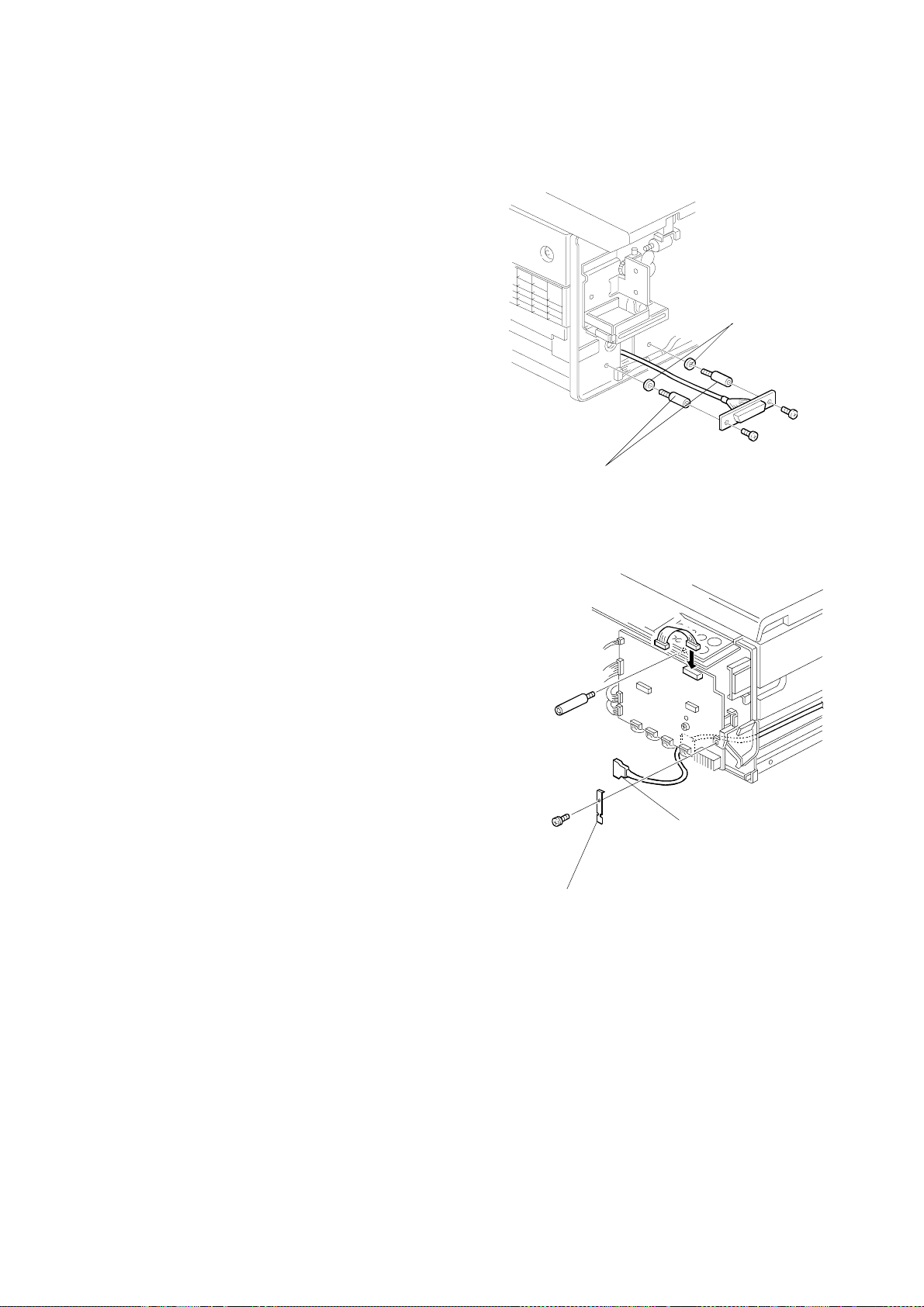
6.2.3 REMOVING THE PRIPORT INTERFACE.
1. Remove the top cover (see Section 6.2.2).
2. Remove the two 4-40 x ¼" x 4-40 jack screws (hex-shaped mounting
studs) securing the digital duplicator port DB25 connector to the
chassis rear panel, using the 3/16" nut driver or wrench.
3. Gently lift the interface card back to clear the upper lip on the chassis
rear panel, and rotate it to a vertical position.
4. Disconnect the ribbon cable at the end of the card connecting it to the
Main Board, and set the card aside in the static-free area.
6.2.4 REMOVI NG THE NETWORK BOARD OR OPTION CARD.
1. Remove the top cover (see Section 6.2.2).
2. Remove the two 4-40 x ¼ " screws securing the faceplate of the
network board (NIB) or the option (Local Printer Port) card to the
chassis rear panel, using the #1 Philips screwdriver.
3. Gently lift the card back to clear the upper lip on the chassis rear
panel, and rotate it to a vertical position.
4. Disconnect the ribbon cable at the end of the card connecting it to the
Main Board, and set it aside in the static-free area.
Network Board
Flat Cable
Interface Port
/Assembly
Disassembly
49
Page 51

DISASSEMBLY PROCEDURES 30 April, 1999
6.2.5 REMOVI NG THE CENTRONICS PORT AND MAIN BOARD.
1. Remove the top cover (see Section 6.2.2).
2. Remove the PRIPORT interface card (see Section 6.2.3).
3. Remove the network board (NIB) or option (Local Printer Port) card
(see Section 6.2.4).
4. Remove the digital duplicator port and NIB or option card ribbon
cables and set them aside with the top cover screws.
5. Remove the RAM and the Flash ROM SIMM sticks from the Main
Board, and place them in the static-safe area - see Section 6.4 for
instructions on removing SIMM’s from their respective carriers.
6. Remove the two M2.6 x 6 screws securing the mini-Centronics
connector of the Main Board to the chassis rear panel, using the #1
Philips screwdriver.
they are an odd size.
7. Remove three 6-32 x 7/16" screws attaching the Main Board to the
chassis, using the #2 Philips screwdriver.
IMPORTANT!
– do not lose these screws, as
8. Slide the Main Board slightly forward through the front slot.
Main Board
50
Page 52

30 April, 1999 DISASSEMBLY PROCEDURES
9. Lift the rear (connector end) of the board up and back
10. Disconnect the power harness at J2.
11. Lift the Main Board out, clear of the chassis, and place it into the
static-safe area.
6.2.6 REMOVING THE PSU
1. Remove the top cover (see Section 6.2.2).
2. Disconnect the AC power, Main Board, and fan cable assembles
from their respective headers on the PSU.
3. Note that the PSU is secured to the chassis with four 6-32 x ¼"
screws.
IMPORTANT!
stud nearest the ground stud DOES NOT have an integral lock
washer, as do the other three screws.
is an internal-tooth version and resides under the circuit board,
between the board and the mounting stud
safety requirements and must be re-assembled in the same fashion.
– note that the 6-32 x ¼ screw going into the mounting
The lock washer for this screw
. This is done to satisfy UL
4. Remove the three 6-32 x ¼" screws with external-tooth locking
washers and the plain 6-32 x ¼ screw attaching the PSU to the
chassis, using the #2 Philips screwdriver.
5. Lift up the PSU board and recover the 6-32 internal-tooth lock
washer described in 4 above. It may be stuck to the bottom of the
PSU circuit board, or sitting on top of the mounting stud.
6. Lift the PSU Board out of the chassis, and place in the static-free
area.
Location of UL
grounding screw
PSU Board
/Assembly
Disassembly
51
Page 53

DISASSEMBLY PROCEDURES 30 April, 1999
6.2.7 REPLACING THE AIR CIRCULATION FAN
1. Remove the top cover (see Section 6.2.2).
2. Remove the PSU (see Section 6.2.6).
3. Remove four 4-40 x ¾" screws securing the fan to chassis center
divider.
4. Remove the fan and connecting cable.
5. Install the new fan and cable, using the four screws removed in 3
above.
6. Reinstall the PSU (see Section 6.3.2).
7. Reinstall the top cover (see Section 6.3.5).
Fan
PSU
52
Page 54

30 April, 1999 ASSEMBLY PROCEDURES
6.3 ASSEMBLY PROCEDURES
Assembly procedures are essentially the reverse of disassembly.
6.3.1 INSTALLING THE PSU
1. Place the chassis on a flat, stable surface.
2. Place the special grounding 6-32 internal-tooth lock washer on the
PSU mounting stud nearest the chassis ground stud.
3. Orient the PSU board so that the fuse is located towards the back
panel of the chassis.
4. Gently place the PSU board on the chassis mounting studs, aligning
the four mounting holes with the holes in the studs, being careful not
to knock the special grounding lock washer off of its position
5. Place the 6-32 x ¼" screw without an integral lock washer through
the mounting hole of the PSU nearest the ground stud. DO NOT
TIGHTEN at this time.
6. Place the three 6-32 x ¼" screws with integral lock washers in the
other three PSU mounting holes.
7. Tighten all four mounting screws using the #2 Phillips screwdriver.
8. Inspect the UL grounding screw of the PSU to make sure the lock
washer underneath the board is securely in the proper position.
9. Attach the fan connector to header TB3, the Main Board connector to
header TB2, and AC connector to header TB1 on the PSU.
6.3.2 INSTALLING THE MAIN BOARD
1. Orient the Main Board so that the two status LEDs are at the leftfront section of the chassis (from the perspective of someone
looking at the front of the chassis).
2. Feed the front (status LED) edge of the Main Board through the slot
in the front chassis just enough so that the rear of the board clears
the lip on the rear chassis, allowing placement of the board onto the
chassis mounting studs.
3. Position the board back toward the rear of the chassis such that the
Diagnostic Test Page switch and the mini-centronics connector each
go through their respective access holes.
/Assembly
Disassembly
4. Place three 6-32 x 7/16" screws into the three chassis mounting
studs to locate the board into position. DO NOT TIGHTEN at this
time.
53
Page 55

ASSEMBLY PROCEDURES 30 April, 1999
5. Place two M2.6 x 6 screws on the holes that secure the minicentronics connector to the rear panel and tighten using the #1
Phillips screwdriver.
screw (e.g., M2.5 x 6) for the originals. Use only the proper screws
for this connector.
6. Tighten the three 6-32 x 7/16" screws that secure the Main Board to
the chassis mounting studs using the #2 Phillips screwdriver.
7. Attach the PSU connector to the header J12.
IMPORTANT!
– do not substitute a different size
Procedures 6.3.3 through 6.3.5 assume that the PSU and Main
Board have already been installed in the chassis – see Sections
6.3.1 and 6.3.2.
6.3.3 INSTALLING THE PRIPORT INTERFACE CARD
1. Position the DB25 connector (J1) of the card through the rear chassis
slot, aligning the threaded mounting holes with those in the rear
chassis.
2. Attach the DB25 connector (J1) to the rear chassis using two 4-40 x
¼" x 4-40 jack screws (hex-shaped mounting studs), with the 3/16
nut driver or wrench.
3. Attach the ribbon cable from J2 on the card to the DUPLICATOR
header J2 on the Main Board.
6.3.4 INSTALLING THE NIB OR OPTION CARD
1. Position the faceplate of the card into the rear chassis slot, aligning
the screw holes with those in the rear chassis.
2. Attach the faceplate to the rear chassis using the two 4-40 x ¼
mounting screws, with the #1 Phillips screwdriver.
3. Attach the ribbon cable to the card, then to the proper connector on
the Main Board (NIB connects to J8, Option to J9), taking care to not
twist the ribbon cable.
54
Page 56

30 April, 1999 ASSEMBLY PROCEDURES
6.3.5 INSTALLING THE TOP COVER AND FRONT PANEL BEZEL OF THE CONTROLLER
1. Carefully re-attach the front bezel, taking care to not break the
locking tabs.
2. Slide the cover back onto the chassis from the back of the Controller.
3. Gently use a small flat-blade screwdriver to pry the cover front lip
slightly up to clear the lip of the front chassis frame.
4. Using both hands, grab the sides and press the front against your
knee or torso. Be careful to not damage or scratch the front bezel if it
is attached. Repeat this process until there is no gap between the lid
and the front bezel. If completed correctly, the front bezel should be
snug against the front chassis panel and the top cover, and will not
rattle.
5. Turn the unit over and lay it on its back.
6. Attach four rubber feet with concentric 4-40 x ¼" screws through the
top cover holes to the four threaded mounting holes on the bottom of
the chassis, with the #1 Phillips screwdriver.
55
/Assembly
Disassembly
Page 57

UPGRADING CONTROLLER FIRMWARE 30 April, 1999
6.4 UPGRADING CONTROLLER FIRMWARE
6.4.1 MAIN BOARD FIRMW ARE UPDATE INSTRUCTIONS
Two (2) ROM images for CPIF26 can be updated:
1) The Adobe firmware (resides in an on-board FLASH ROM chip on the
Main Board).
2) The CPIF26 firmware (resides on a SIMM connected to the Main
Board).
The instructions below describe the procedures to perform either or both
or these updates.
6.4.1.1 Materials and Files
Obtain and have ready to use the following materials and equipment. All
items marked with a (*) are included in the Controller Service Kit (see
Section 5.1.2).
6.4.1.1.1 Hardware
• An
• A
• An
• A
• A
• A
6.4.1.1.2 Software
• The
• The
RS-232 ribbon cable adapter
end and a 10-pin header on the other.
2 meter or longer RS-232 extension serial cable
DB9 connector on one end and a female DB9 connector on the other.
IEEE 1284 Bi-directional mini-centronics cable
between your PC and the Controller unit.
PC with an IEEE 1284 Bi-directional interface port and an
available serial port running the Windows 95 with IE4.01 SP1, or
Windows 98 operating system.
PRIPORT-to-controller video cable
PRIPORT
ROM image file
area, the Elesys web site, or the Service CDs (see Section 5.1.2 for
the Service CDs), unZIPp’d if necessary, and stored in a local
directory on your computer:
parallel port download utility
Service CDs into
you stored the ROM images
download utility physically downloads the ROM image into the
CPIF26 Flash ROMs:
• As a reference, view or print “
locate connectors and jumpers.
(*) with a DB9F connector on one
(*) with a male
(*) that attaches
(*).
.
must be downloaded from your local support
(*) must be downloaded from the
the same working directory on your local PC where
. The PC DOS IEEE 1284 centronics
2.1.2 Main Board Layout Diagram
” to
56
Page 58

30 April, 1999 UPGRADING CONTROLLER FIRMWARE
6.4.1.2 Prepare the Controller and computer.
DANGER
The Controller's power supply becomes hazardous with the chassis
opened. It exposes you to severe electrical shock if you do not
disconnect the power cord before opening.
CAUTION
The electronic components in this unit can be damaged by static
discharge. Please ensure that you are properly grounded before
touching any portion of the electronics. Also, touch the chassis with
your finger before connecting test cables, setting switches or
reattaching components.
Prepare the controller for the ROM update process by doing the
following:
1. Turn off and unplug the power to the CPIF 26 unit. Remove all other
cables from the back panel.
2. Remove the top cover and front bezel using the procedure outlined in
Section 6.2.2.
3. Remove the network board (NIB) or option (Local Printer Port) card
using the procedure outlined in Secti on 6.2. 4.
4. Locate the Serial Port header JP2 towards the rear of the main board.
Attach the header end of the RS-232 ribbon cable to JP2. Make sure
pin 1 (with a red stripe or marked on the cable) is towards the front of
the Controller.
5. Attach the DB9 end of the cable to one end of the extension RS232
serial cable. Attach the other end of the extension cable to the
available serial COM port on your computer.
6. On the computer, start an MSDOS session and get into the working
directory where you downloaded the ROM image and centdown
files.
/Assembly
Disassembly
57
Page 59

UPGRADING CONTROLLER FIRMWARE 30 April, 1999
7. Configure or setup either the standard Windows Hyperterminal or a
substitute on your PC:
• Press
Start\Programs\Accessaries\Communications\Hyperterminal
• Choose “connect direct to COM1” or “COM2” as appropriate
• Set to 9600-8-N-1
• Locate DIP switch SW1 under PRIPORT interface adapter board.
• Set SW 8 ON (SW 4 on Production boards) to enter monitor
mode.
• Connect a parallel cable to unit.
IMPORTANT
: Make sure no
other devices (e.g., ZIP drives) are connected to the parallel port.
DANGER
To complete this process, you must reattach the power cable and
operate the unit with an exposed power supply. Use caution to
avoid touching any part of the power supply, as it contains exposed
high voltages capable of causing a lethal electrical shock.
• Re-connect the power cord to the controller and turn it on.
• In Hyperterm, press Enter a few times
• If you've set the baud rate correctly, you should get a single “>”
prompt:
r4300>
58
Page 60

30 April, 1999 UPGRADING CONTROLLER FIRMWARE
.4.1.3 CPIF26 Firmware SIMM Flash ROM update procedure
6
To update the CPIF26 SIMM flash ROM:
• Press ENTER to get the single prompt:
r4300>
• Type “z” and ENTER.
• Now you get a double “>>” prompt:
r4300>>
• Type “boot cent” .
• A message appears indicating it is waiting for the centronics port.
• Click on the MSDOS window and type:
centdown eleXXX.rom (where “eleXXX.rom” should be replaced by
the actual file name for the version of the CPIF26 ROM you are
downloading).
• Go to the Hyperterm window and answer “Y”.
• Click on the DOS window again to activate it.
• The download commences automatically. The monitor will first
indicate it is erasing Bank 1, the SIMM flash ROM. Then it will count
up by percentage complete. (The selection of which bank to
download into is done automatically for you.)
• W hen finished, it will show the CPU registry and say “buss error” ignore this error, since it is a normal part of the download process.
If you are updating only the CPIF26 Flash ROM, skip to section 6.4.1.5.
• Cycle power on the Controller.
/Assembly
Disassembly
59
Page 61

UPGRADING CONTROLLER FIRMWARE 30 April, 1999
6.4.1.4 Adobe Flash ROM update
To update in the Adobe on-board flash ROM:
• Press ENTER to find the single prompt:
r4300>
• Type “z” and ENTER.
• Now you get a double prompt:
r4300>>
• Type “boot cent” .
• A message appears indicating it's waiting on the centronics port.
• Now in a DOS window, type:
centdown adobe.rom (where “adobe.rom” should be replaced by the
actual file name for the new version of the Adobe ROM).
• Go to the Hyperterm window and answer “Y”.
• Click on the DOS window again to activate it.
• The download automatically. The monitor will first indicate it is erasing
Bank 0, which is the on-board flash ROM. Then it will count up by
percentage complete. (The selection of which bank to download into
is done automatically for you.)
• W hen finished, it will show the CPU registry and say “buss error” ignore this error, since it is a normal part of the download process.
• Cycle power to get the single prompt again.
60
Page 62

30 April, 1999 UPGRADING CONTROLLER FIRMWARE
6.4.1.5 Reset to factory default NVRAM settings.
• Set SW 7 (SW 3 on Production boards) to ON (SW 1-4 are OFF, SW
5-8 are all ON;
SW 1-4 are all ON on Production boards)
• Type: z
• Then type: boot ps
• Monitor output should say it is resetting factory defaults.
• Set SW 7 to OFF (SW 3 on Production boards)
• Cycle power and you'll get the single prompt again.
• Type: z
• Then type: boot ps
• It should say, among other things :
Flash ROM [SIMM] Version: 17.09X.XXX
Copyright 1998 Elesys, Inc. All rights reserved.
6.4.1.6 Check that the update procedure(s) worked.
• Set SW 8 to OFF on Beta main boards (SW 4 on Production main
boards) to enable autobooting again.
• Power down the unit and disconnect the serial and parallel cables leave power and PRIPORT cables connected.
• Reinstall the network board (NIB) or option (Local Printer Port) card
using the procedure outlined in Secti on 6.3. 4.
• Power on the unit again and print the Diagnostic Test Page by
pressing the test button on the back. Verify that the new firmware
revision has been updated as shown on the bottom of the Diagnostic
Test Page.
• Proceed with the next section when you are satisfied that the
Controller is operating properly.
6.4.1.7 Finish up.
• Disconnect the power and PRIPORT cables from the Controller.
• Replace the cover and front bezel (see Section 6.3.5).
61
/Assembly
Disassembly
Page 63

UPGRADING CONTROLLER FIRMWARE 30 April, 1999
6.4.2 NIB (NETWORK INTERFACE BOARD) FIRMWARE UPDATE INSTRUCTIONS.
The NIB firmware inside the CPIF 26 is contained in a flash ROM located
on the board. . It is updated using a ROM image file with a special FTP
download utility. These instructions describe how to perform an update
of this ROM.
6.4.2.1 Materials Required To Perform the NIB Firmware Update
Obtain and have ready to use the following materials and equipment. All
items marked with a (*) come in the Controlle r Service Kit (see Section
5.1.2).
6.4.2.1.1 Hardware
cross-connect LAN cable
• A
computer to the controller.
PC with a 10Base-T LAN card installed, running Windows 95
• A
(with IE4.01 SP1) or Windows 98 operating systems, and
known/demonstrated ability to communicate to another
computer via the IPX/SPX and TCP/IP protocols.
(*) of sufficient length to connect the
6.4.2.1.2 Additional Recommended Hardware
PRIPORT-to-controller video cable
• A
PRIPORT
• A
.
(*).
62
Page 64

30 April, 1999 UPGRADING CONTROLLER FIRMWARE
6.4.2.1.3 Software
• The
ROM image file
must be downloaded from your local support
entity, the Elesys web site, or the Service CDs (see Section 5.1.2 for
the Service CDs), unZIP’d if necessary, and stored in a local directory
on the computer being used to update the controller.
• The
FTP download utility
(*) must be installed to your computer the
Service CD. The FTP Download utility is a Windows 95/98 program
that physically downloads the ROM image into the NIB Flash ROM.
Simply unzip file to a temporary directory on the computer and
double-click on SETUP.EXE to install the program on the computer
being used to update the controller.
• The
MAP LAN utility
(*) must be installed to your computer from the
Service or Installation CDs (see Section 5.1.2 for the Service CDs).
The utility is located in the following directory:
[CDROM drive letter]:\WIN\LAN Tools\MAP
The MAP utility is a Windows 95/98 program that ‘discovers’ the NIB in
the Controller and allows you to query and manipulate setup values
using a standard web browser, such as Netscape or Internet Explorer.
Simply double-click on Setup.exe to install the MAP utility on the
computer being used to update the controller:
standard web browser
• A
must be installed on the computer. Any
version of Netscape or Internet Explorer (i.e., the version that ships
with Windows) will be adequate. Make sure the web browser is setup
to connect to the Internet direct via a LAN, and NOT through a proxy
server.
6.4.2.1.4 Other
• The NIB access password from the customer, if it has been changed
from the default value of
sysadm
63
/Assembly
.
Disassembly
Page 65

UPGRADING CONTROLLER FIRMWARE 30 April, 1999
6.4.2.2 NIB Flash ROM Update Procedure.
1. Connect the LAN card in the computer to the NIB in the Controller
using the cross-connect LAN cable.
2. If you have a PRIPORT available,
a) Connect the Controller to the PRIPORT using a standard
controller-to-PRIPORT video cable,
b) Power on the PRIPORT,
c) Put the PRIPORT ONLINE, and enable Auto Cycle.
3. Power on the Controller.
4. W ait 3 minutes for the Controller to warm up.
5. Obtain the current NIB firmware revision number – see Section
6.4.2.3.
6. Confirm that the current NIB firmware revision is different from that
of the ROM image you wish to install.
7. Obtain the TCP/IP address of the Controller – see Section 6.4.2.3.
8. Start the
9. Click on
10. Enter or use the browse option to select the ROM image filename,
and click on OK.
11. Enter the IP address obtained in 7 above.
12. Enter the NIB password.
13. When the download process is complete, cycle power on the
controller.
14. Obtain the current NIB firmware revision number – see Section
6.4.2.3.
15. Verify that the version number of the firmware has been changed to
the new version corresponding to that of the ROM image file. This
confirms a successful firmware update.
16. If you entered any TCP/IP parameters (IP Address, Subnet Mask,
or Default Gateway) into the unit, return these parameters to their
original values.
FTP Download
File
and select
program.
Download…
The NIB firmware update procedure has now been completed.
64
Page 66

30 April, 1999 UPGRADING CONTROLLER FIRMWARE
6.4.2.3 Miscellaneous Support Procedures to the NIB Firmware Update
6.4.2.3.1 Generating a NIB Status Page printout on the PRIPORT.
• Start the MAP utility,
• After identification of the controller, click on the IPX/SPX HTML link,
• Click on Network Configuration,
• Click on Configure Status Page under Others,
• Put a dot in the PostScript circle,
• Enter the NIB password,
• Generate the status page clicking on the Generate Now button,
• Close the web browser.
• The items of interest are:
1) the NIB firmware revision (Version in the upper right-hand
corner of the page).
2) the IP Address (Protocol Address under TCP/IP Network
Information section).
6.4.2.3.2 Obtaining the current NIB ROM version using MAP and a web browser.
• Start the MAP utility,
• After identification of the controller, click on the IPX/SPX HTML link,
• Click on Network Configuration,
• Click on Unit Info at the bottom of the page,
• Write down the ROM Version number,
• Close the web browser.
6.4.2.3.3 Obtaining the current Controller TCP/IP address.
• On the NIB Status Page printout, circle or otherwise note the Protocol
Address under the TCP/IP Network Information section. If the
TCP/IP Protocol Address is Not Configured, you will need to
configure the TCP/IP settings – see Section 6.4.2.3.4.
-- OR --
• Use the MAP utility and web browser to read the IP address:
• Start the MAP utility,
• After identification of the controller, click on the IPX/SPX HTML
link,
• Click on Network Configuration,
• Click on Setup TCP/IP,
• Copy down the IP Address in the form of xxx.xxx.xxx.xxx to a
piece of paper.
• Close the web browser.
/Assembly
Disassembly
65
Page 67

UPGRADING CONTROLLER FIRMWARE 30 April, 1999
6.4.2.3.4 Setting an IP address using MAP and a web browser.
• Start the MAP utility,
• After identification of the controller, click on the IPX/SPX HTML link,
• Click on Network Configuration,
• Click on Setup TCP/IP,
• Enter an IP Address of 90.0.0.200,
• Enter a Subnet Mask of 255.255.255.0,
• Enter a Default Gateway of 1.1.1.1,
• Leave all other settings as they were,
• Enter the NIB password,
• Click on the Accept Settings button,
• Wait for one of several events to occur:
1) the PRIPORT generates a new NIB Status Page showing the
TCP/IP information just entered,
2) the Controller returns an “Update Successful” HTML page,
3) 3 minutes passes.
• Close the web browser (ignore any ‘timed out’ messages),
• Cycle the power on the Controller,
• Wait 3 minutes before proceeding.
66
Page 68

30 April, 1999 UPGRADING CONTROLLER FIRMWARE
6.4.2.4 NIB Firmware Update FAQs
Q1
Can I use a standard LAN connection between my computer and the
Controller to perform the update instead of the cross-connect cable?
A1 Probably - the answer depends upon the configuration of your LAN. The
cross-connect cable ensures a ‘clean’ LAN connection between the NIB
and the computer. Although every effort has been made to prevent
potential conflicts through proper design of the utilities, a server on the
LAN could interfere with the operation of MAP, the FTP Download
program, the NIB, or some combination of the above. A cross-connect
cable eliminates a lot of variables and allows for a quick and easy way to
perform the update.
Q2
Can I use some other utility on my PC besides MAP and a web browser to
set an IP address in the Controller?
A2 Yes, you can use the BootP program supplied on the Installation CD.
Instructions for how to use the BootP program are located in the section
entitled
BootP Lite in a Windows environment
in Chapter 4 of the
Controller User’s Guide. The program has the advantage of allowing you
to set the IP address without knowing the NIB password. However, you
must know the NIB’s network hardware address, so you may find it more
complicated to use. In addition, it will not allow you access to the NIB to
print a status page.
Q3
How do I check to see if my computer is set up to communicate via the
IPX/SPX and TCP/IP protocols?
A3 For instructions on checking for the IPX/SPX compat ibility, see
to a Peer-to-Peer Ethernet Network
in Chapter 2 of the Controller User’s
Connecting
Guide. TCP/IP is very similar, but has some additional variables that may
need to be set. There is nothing fancy about either installation to support
this procedure – basically, the LAN card in the computer just needs to be
bound to these two protocols. If in doubt, see your System Administrator
for details on setting up your computer.
Q4
Can I do the procedure without a PRIPORT?
A4 The PRIPORT is used in this procedure only to print a NIB Status Page.
You will be able to communicate with the Controller, perform the update,
and verify that the new Controller firmware revision has been installed
using just the required software. However, you will not be able to verify
any other aspects of Controller/PRIPORT operation. In addition, the NIB
Status Page provides a convenient method for keeping track of all
changes made to NIB setup.
/Assembly
Disassembly
67
Page 69

UPGRADING CONTROLLER FIRMWARE 30 April, 1999
Q5
What do I do if the MAP utility returns a screen saying, “No network
printers found on network.”?
A5 This error will occur if one or more of the following conditions exists:
1)
The MAP utility was initiated before the 3-minute warm-up pe rio d of
the Controller had completed
controller has been on at least 3 minutes.
2)
There is a problem with the hardware connection between the NIB in
the Controller and that of the PC
eliminated if you are using the cross-connect LAN cable supplied with
the Service Kit (see Section 5.1.2). Otherwise, you will have to check
that a path exists between the Controller, the network drop(s), and
the PC.
3)
There is a problem in the IPX/SPX or TCP/IP support in the PC
must be corrected in the PC – see Q2/A2 above.
4)
The NIB in the Controller has had its IPX/SPX and TCP/IP support
disabled
occurrence. Nevertheless, it can happen, and can only be remedied
by resetting the NIB using the hardware jumpers on the card itself. A
detailed procedure for doing this is may be found toward the end of
Chapter 4 of the Controller User’s Guide for the CPIF 26. It will also
force resetting of all other NIB parameters, including the IP Address,
back to factory default values (thus, you will have to set those up
again before proceeding).
. This condition has the most remote possibility of
. To fix this, simply restart MAP after the
. This condition can be virtually
. This
Q6
A6 Try the default password
What do I do if the NIB will not accept the password I enter?
choices:
1) Obtain the correct password from the customer.
2) Reset the NIB using the detailed procedure found toward the end of
Chapter 4 of the Controller User’s Guide for the CPIF 26. Performing
this procedure will allow the NIB to respond to the default
password. It will also force resetting of all other NIB parameters,
including the IP Address, back to factory default values (thus, you will
have to set those up again before proceeding).
sysadm
. If that does not work, you have two
sysadm
68
Page 70

30 April, 1999 UPGRADING CONTROLLER FIRMWARE
6.4.3 HARDWARE PROCEDURE TO RESET THE NIB TO FACTORY DEFAULT VALUES.
This procedure is also covered in the Chapter 4 of the Controller User’s
Guide.
DANGER
The Controller's power supply becomes hazardous with the chassis
opened. It exposes you to severe electrical shock if you do not
disconnect the power cord before opening.
CAUTION
The electronic components in this unit can be damaged by static
discharge. Please ensure that you are properly grounded before
touching any portion of the electronics. Also, touch the chassis with
your finger before connecting test cables, setting switches or
reattaching components.
1) Remove all cables attached to the controller
2) Remove the top cover – see Section 6.2.2.
3) Identify but do not remove the board – see Section 6.2.3.
4) Locate the Reset Jumper
the row of jumpers near the UTP port.
5) Move jumper
OP2
to the ON position, so that the jumper covers the
center pin and the pin nearest the jumper designator.
6) Temporarily replace the top cover on the controller using at least
one screw to keep it in place.
7) Plug in the power cord to the controller – DO NOT connect it to the
network at this time.
8) Power on the controller.
9) The NIB status lights will blink as it performs its diagnostic tests –
the green LED blinks three times, then you will see an alternating
green/amber light sequence.
green/amber light sequence, power off the controller
10) Remove the power cord from the controller, then the top cover.
11) Move the Reset Jumper
jumper covers the center pin and the pin nearest the
designation.
12) Re-install the top cover (see Section 6.3.5), the power and LAN
cords, and re-connect to the PRIPORT.
OP2
on the board (NIB). It is located in
When you see the alternating
.
OP2
back to its
OFF
position, so the
OFF
/Assembly
Disassembly
This completes the NIB hardware reset procedure.
69
Page 71

UPGRADING CONTROLLER RAM 30 April, 1999
6.5 UPGRADING CONTROLLER RAM
This procedure is also covered in the Appendix B of the Controller
Reference Manual.
CAUTION
The electronic components in this unit can be damaged by static
discharge. Please ensure that you are properly grounded before
touching any portion of the electronics. Also, touch the chassis with
your finger before connecting test cables, setting switches or
reattaching components.
6.5.1 MEMORY (SIMM) BOARD INSTALLATION
6.5.1.1 General guidelines for installing memory in the controller.
1) The controller must have at least the minimum/standard amount of
memory installed, as specified under the Printer Features section of
the Controller User’s Guide, in order to function correctly.
2) The controller must have a SIMM board installed in slot 1.
6.5.1.2 Outline for Memory Upgrades
1) Remove any existing/already installed SIMMs.
2) Install existing and new SIMMs per the SIMM-slot placement rules.
70
Page 72

30 April, 1999 UPGRADING CONTROLLER RAM
6.5.1.3 SIMM-slot placement rules.
6.5.1.3.1 Case 1: After removing any existing SIMM(s), a total of one SIMM is to
be installed.
This situation would occur if, for example, you were to replace a partiallyor non-functioning SIMM with a new one. In this situation, simply
substitute a new SIMM for the existing one, using only slot 1
. The new
SIMM must meet or exceed the minimum memory requirements for your
controller. For the sake of future upgrade compatibility, if the new SIMM
is of the single-sided configuration (see Figure 6.5.1.3.5-1), it should
have a PD (Presence Detect) jumper installed.
6.5.1.3.2 Case 2: After removing any existing SIMM(s), two SIMMs are to be
installed, at least one of which is a double-sided SIMM (see Figure
6.5.1.3.5-2).
In this configuration, the double-sided SIMM board must be installed into
slot 1. This is regardless of respective memory sizes of the SIMM
boards –
the double-sided board always goes into slot 1
. If both SIMMs
are double-sided, it does not matter which one goes into which slot.
6.5.1.3.3 Case 3: After removing any existing SIMM(s), two single-sided SIMMs
are to be installed (see Figure 6.5.1.3.5-1).
This configuration could occur if, for example, you wanted to simply add
a second SIMM to the controller’s factory-shipped configuration. In this
case,
jumper installed
the single-sided SIMM to be installed into slot 2 must have a PD
.
6.5.1.3.4 Unsupported Memory Configurations
Memory configurations not listed under the rules above are not
supported, or will not yield the correct amount of memory for the
controller. This includes any combina tion of boards which:
1) Does not yield the minimum amount of memory needed by the
controller.
2) Utilizes 1 or 2 Mbyte SIMMs.
3) Utilizes a single-sided SIMM in slot 2 that does not have a PD jumper
installed.
If you believe your memory configuration is supported, but it is not
yielding the correct amount of memory, see the Section 6.5.3 on
Troubleshooting a Memory Upgrade
.
/Assembly
Disassembly
71
Page 73

UPGRADING CONTROLLER RAM 30 April, 1999
6.5.1.3.5 SIMM PD Jumpers
Figure 6.5.1.3.5-1
shows an example of a
single-sided SIMM
board with a PD jumper
installed. The jumper,
shown in the second
(PD2) position, may be
in any of the four
possible positions
shown in the diagram.
Figure 6.5.1.3.5-1. Example of a singlesided SIMM with one PD jumper
installed.
Figure 6.5.1.3.5-2 shows an
example of a double-sided SIMM
board, where the memory chips are
attached to both sides of the SIMM
board.
Figure 6.5.1.3.5-2. Example
of a double-sided SIMM.
All memory boards used in upgrading the memory configuration of the
controller must adhere to the JEDEC standards for 72-pin (72-pin 60ns
EDO SIMM, non-parity, at 5 volts with 2K maximum refresh rate). Single
sided
SIMMs placed in slot 2 must have at least one of the Presence
Detect jumpers in place: PD1, PD2, PD3, or PD4.
For more information, locate JEDEC Standard No. 21-C. A copy may be
obtained by searching the following web site:
http://www.jedec.org.
-
72
Page 74

30 April, 1999 UPGRADING CONTROLLER RAM
6.5.1.3.6 RAM Upgrade Configuration Table
Table 6.5.1.3.6 is provided as a guide when upgrading memory.
It is recommended that memory be upgraded only in the configurations
shown.
Total Controller Memory Slot 1 Slot 2
8MBytes 8 MByte SIMM
12 MBytes 8 MByte SIMM
16 MBytes 8 MByte SIMM
ds
ds
ds
(empty)
4 MByte SIMM
8 MByte SIMM
ds
16 MBytes 16 MByte SIMM (empty)
20 MBytes 16 MByte SIMM 4 MByte SIMM
24 MBytes 8 MByte SIMM
ds
16 MByte SIMM
32 MBytes 16 MByte SIMM 16 MByte SIMM
ssj
ssj
32 MBytes 32 MByte SIMM (empty)
36 MBytes 32 MByte SIMM
40 MBytes 32 MByte SIMM
40 MBytes 8 MByte SIMM
48 MBytes 32 MByte SIMM
64 MBytes 32 MByte SIMM
ds
ds
ds
ds
ds
4 MByte SIMM
8 MByte SIMM
32 MByte SIMM
16 MByte SIMM
32 MByte SIMM
ds
ds
ds
64 MBytes 64 MByte SIMM (empty)
68 MBytes 64 MByte SIMM 4 MByte SIMM
68 MBytes 4 MByte SIMM 64 MByte SIMM
72 MBytes 8 MByte SIMM
ds
64 MByte SIMM
80 MBytes 16 MByte SIMM 64 MByte SIMM
96 MBytes 32 MByte SIMM
ds
64 MByte SIMM
128 MBytes 64 MByte SIMM 64 MByte SIMM
128 MBytes 128 MByte SIMM
132 MBytes 128 MByte SIMM
136 MBytes 128 MByte SIMM
144 MBytes 128 MByte SIMM
160 MBytes 128 MByte SIMM
196 MBytes 128 MByte SIMM
256 MBytes 128 MByte SIMM
ds
ds
ds
ds
ds
ds
ds
(empty)
4 MByte SIMM
8 MByte SIMM
16 MByte SIMM
32 MByte SIMM
64 MByte SIMM
128 MByte SIMM
ssj
ssj
ssj
ssj
ds
ds
NOTES:
ds – Typically, the configuration of this SIMM is double-sided.
ssj – In single-sided configuration, this SIMM
must
have the PD jumper installed
for the memory upgrade to function correctly.
/Assembly
Disassembly
Table 6.5.1.3.6. Supported memory configurations.
73
Page 75

UPGRADING CONTROLLER RAM 30 April, 1999
6.5.1.4 Protecting SIMM Boards SIMM-slot placement rules.
SIMM boards can be easily damaged by small amounts of static
electricity. To remove any static electricity from your body:
• Touch the surface of the antistatic package before removing the
board from its package. When handling the board, frequently touch
bare metal on the printer or the antistatic bag or wear an antistatic
wrist strap.
• Avoid moving about the work area to prevent generating static
electricity.
• Handle the board carefully at all times. Avoid flexing it or touching its
components.
When removing a board from the antistati c package, avoid touching th e
metal traces on the SIMM board through handling only by the edges.
6.5.1.5 Installing SIMM Boards SIMM-slot placement rules.
The following section describes procedures to remove the controller’s top
cover and insert a SIMM board.
6.5.1.5.1 Accessing the SIMM Slots.
1. Remove the top cover of the controller - see Section 6.2.2.
2. Locate the memory SIMM memory slots. Note the location of slot 1.
If only one SIMM is present, it is always located in slot 1.
Figure 6.5.1.5.1 Locating SIMM slot 1.
74
Page 76

30 April, 1999 UPGRADING CONTROLLER RAM
6.5.1.5.2 Removing currently installed SIMMs.
Always begin SIMM removal with slot 1.
slot placement rules
, for information as to which type of SIMM is installed
into which slot.
1. Locate the metal locking tabs
holding the SIMM in place on
either side of the board slot.
Refer to Section 6.5.1.3,
Figure 6.5.1.5.2-1. Locate
the SIMM locking tabs.
SIMM-
2.
Gently
push down on the
metal locking tabs while
rotating the board toward the
back of the slot - shown as
rotating down and to the left in
Figure 6.5.1.5.2-2 - until it
clears the metal tabs. As it
may take two hands to hold
down the metal locking tabs
on both sides of the board
simultaneously, you may want
to call for another person to
assist you in this process.
3. Remove the existing SIMM
and place into an antistatic
bag.
Figure 6.5.1.5.2-2. Removing
an existing SIMM board.
/Assembly
Disassembly
75
Page 77

UPGRADING CONTROLLER RAM 30 April, 1999
6.5.1.5.3 Installing SIMMs.
For configurations where two SIMMs are to be installed, always begin
installation with slot 2. Refer to Section 6.5.1.3,
rules
, for information as to which type of SIMM is installed into which slot.
SIMM-slot placement
1. Remove the new SIMM from
its antistatic package. Hold
the board with your forefingers
on the side edges and your
thumbs against the back
edge, as shown in Figure
6.5.1.5.3-1. Turn the board so
the notch on one end is on the
bottom and the metal teeth
face toward the slot.
2. Hold the SIMM board at a
30-degree angle to the slot
and push the edge of the
board evenly and firmly into
the slot, as shown in Figure
6.5.1.5.3-2.
Figure 6.5.1.5.3-1. Positioning
the SIMM.
30°
Figure 6.5.1.5.3-2. Seating the
SIMM board in the socket.
76
Page 78

30 April, 1999 UPGRADING CONTROLLER RAM
3. Rotate the board to the
right until the board
‘clicks’ into the metal
locking tabs, securing
the board in place - see
Figure 6.5.1.5.3-3.
4.
Gently
rock the SIMM
back and forth. If it is
seated correctly, it will
not lift away from the
slot. If it lifts up, you
Figure 6.5.1.5.3-3. Securing the
SIMM board in the socket.
have not pushed it firmly
enough into the slot, and
you must try installing
again.
5. If another SIMM is to be installed (i.e., slot 1), simply repeat these
installation steps.
6.5.1.5.4 Finishing up.
1. Replace the top cover – See Section 6.3.5.
2. Connect the Controller to a PRIPORT.
3. Power on the PRIPORT.
4. Plug in the power cord and switch the Controller ON.
/Assembly
Disassembly
77
Page 79

UPGRADING CONTROLLER RAM 30 April, 1999
6.5.2 TESTING A MEMORY UPGRADE
The simplest way to test a memory upgrade performed on the controller
is to do the following:
Figure 6.5.2-1. ‘Ready to Print’ status light condition.
1) Check status lights on the controller front panel. After performing a
power-on self check, the controller should show the status light
condition for “Ready to print”, as shown in Figure 6.5.2-1. (See
Section 5.6,
complete listing as to what conditions are indicated by the status
lights, and how to interpret them.)
2) Print a Diagnostic Test Page and note the area on the report which
states the amount of memory available to the printer, as shown in
Figure 6.5.2-2.
LED Status Light Sequence and Conditions
, for a
78
Page 80

30 April, 1999 UPGRADING CONTROLLER RAM
Figure 6.5.2-2. Using the Diagnostic Test Page to verify correct
memory installation.
Printing this page verifies that the;
a) Controller is able to communicate with the PRIPORT,
b) memory installation was done correctly,
c) amount of memory you installed is what you expected, and
d) memory is functioning correctly.
If the test page does not indicate the correct amount of memory, or there
is some other problem, proceed with the Section 6.5.3).
79
/Assembly
Disassembly
Page 81

UPGRADING CONTROLLER RAM 30 April, 1999
6.5.3 TROUBLESHOOTING A MEMORY UPGRADE
A memory upgrade/installation can fail for several reasons:
1) In a two-memory-board installation, a single-sided memory card has
been installed into slot 1 that does not have a PD jumper.
2) A memory board is not seated properly when installed.
3) Memory is installed corre ctly bu t is of insufficient size.
4) One or both of the memory boards has failed.
Check the following tables for the symptom you are experiencing to
identify a course of action.
Symptom Most Probable Causes What to do
Diagnostic Test
The
Page
indicates that
the controller is
recognizing memo ry,
but it is not of the
expected size.
1) The SIMM installed
in slot 1 is not a
double-sided
memory card
.
Procure a SIMM that is
double-sided and install into
slot 1.
2) The SIMM installed
in slot 2 is not seated
properly
3) The installed
SIMM(s) has (have)
a memory size that is
actually
it’s specification.
Table 6.5.3-1. Troubleshooting – Incorrect Diagnostic Test Page.
smaller than
Properly re-install the SIMM in
slot 2.
a) Check to make sure the
board part numbers are
correct for the SIMM size.
If not, obtain and install
the correct ones for the
desired memory size.
b) The SIMM could have a
fault in which it only
reports part (for example,
one-half) of the memory
for which it is rated. In this
case, the board must be
returned to the vendor for
replacement.
80
Page 82

30 April, 1999 UPGRADING CONTROLLER RAM
Symptom Most Probable Causes What to do
The controller status
lights indicate a
controller unit failure.
1) The SIMM in slot 1 is
not seated correctly.
2) The SIMM in slot 1 is
at fault.
3) Total memory being
reported is less than
the standard memory
configuration for your
controller.
Properly re-install the SIMM in
slot 1.
If you have a SIMM in slot 2
and it has a memory size
sufficiently large for the
standard memory
requirements of your
controller, try installing it in
the slot 1 position. If the
controller responds positively
to this, you probably have a
faulty SIMM, which must be
returned to the vendor for
replacement.
a) The combination of SIMMs
yields a size under the
standard memory
configuration for your
controller. You must
install the minimum
amount of memory so the
controller will function.
b) SIMMs in either slot do not
report the correct amount
of memory available to the
controller. Try swappi ng
the SIMMs from slot 1 to 2
to see if the controller will
give a ‘ready to print’
status. If it will not, and
you are sure the SIMMs
are of the correct size,
they are probably
defective and must be
returned to the vendor for
replacement.
Table 6.5.3-2. Troubleshooting - status light problem.
/Assembly
Disassembly
81
Page 83

30 April, 1999 CPIF-26
7. PARTS LIST
7.1 CPIF-26
11
9
10
5
2
6
7
8
4
1
3
Index
No.
1 C919 0010 C02001 Fan Ass’y 1
2 C919 0020 C02002 PSU Ass’y 1
3 C919 0050 C02011 Metal Chassis Ass’y
4 C919 0060 M02015 Main Board Ass’y - RMA 1
5 C919 0070 M02016 Flash ROM SIMM – Unprogrammed 1
6 C919 0080 M02017 32MB SIMM 1
6 C919 0090 M02018 64MB SIMM 1
6 C919 0100 M02019 128MB SIMM 1
7 C919 0110 T02007 Output Board 1
8 C919 0120 T00008 26-pin Ribbon Cable 1
9 C919 0130 T02014 Network Board Ass’y - RMA 1
10 C919 0140 T02015 Network Ribbon Cable 1
11 C919 0030 C00003 U.S. Power Cord 1
11 C919 0040 C00004 Euro Power Cord 1
Part No. Description
(including the main switch and harness, etc.)
83
Assembly
Q’ty Per
1
List
Parts
Page 84

CPIF-26 30 April, 1999
Index
No.
- C919 0150 T02016 Parallel Cable 1
- C919 0160 I30003 Video Interface Cable 1
- C919 0170 GR0022 CD-ROM 1
- C919 0180 T02017 2GB HDD 1
- C919 0190 T02018 HDD Ribbon Cable 1
- C919 0200 U02001 Serial Ribbon Cable - 10 pin to DB9F
- C919 9501
Part No. Description
(included in the service kit #C219-9501)
U02002 Controller Service Kit
(For details, refer to section 5.1.2.)
Q’ty Per
Assembly
1
1
84
Page 85

30 April, 1999 PC CONTROLLER I/F KIT TYPE-600
7.2 PC CONTROLLER I/F KIT TYPE-600
Index
No.
1 C544 1016 IC – Interface 1
2 C544 1010 Interface Board 1
3 C544 2105 Insulating sheet – 145 x 200 1
4 C544 1520 Interface Cable – Interface Board 1
5 C544 2116 Stud – 50mm 2
6 0807 3083 Spacer – 10mm 2
7 C544 2110 PCB Stud – 64mm 2
8 C544 2112 Harness Support Bracket 1
9 0313 0350B Philips Pan Head Screw – M3 x 35 1
10 0960 3008W Philips Flange Screw – M3 x 8 3
11 0960 4008W Philips Flange Screw – M4 x 8 3
12 C544 1600
13 1105 0042 Wire Band 1
14 C544 2111 PCB Collar 1
15 C544 1602 Flat Cable – NA2 1
Part No. Description
Flat Cable –
N810/NA33/NA3/NB2/RN925/N850
85
Assembly
Q’ty Per
1
List
Parts
Page 86

PC CONTROLLER I/F KIT TYPE-600 30 April, 1999
Index
No.
16 C203 2031 Main Board Spacer 1
17 C531 5300 Stud – Bracket – Interface 2
18 C531 5310 Interface Board Bracket 1
19 0951 3025Z Philips Screw with Flat W asher – M3 x 25 1
20 C209 8500 Stud – Main Board 1
21 0951 4006Z Philips Screw with Flat W asher – M4 x 6 1
22 0314 0080Z Philips Screw – M4 x 8 2
23 0951 3006Z Philips Screw with Flat W asher – M3 x 6 2
24 R326 5302 Interface Board Stud 2
25 C200 2596 Main Board Stud – Long 4
26 0314 0080Z Philips Screw – M4 x 8 2
27 0951 3006Z Philips Screw with Flat W asher – M3 x 6 4
28 C544 1601 Flat Cable – N865 1
29 C544 2120 Stud – 35mm 3
30 0951 3006Z Philips Screw with flat Washer – M3 x 6 3
31 0314 0080Z Philips Screw – M4 x 8 2
32 C544 2320 Set for Part 1A 1
33 C544 2000 Set for Part 1B 1
34 C544 2050 Set for Part 1C 1
35 C544 2330 Set for Part 1D 1
Part No. Description
Assembly
Q’ty Per
86
Page 87

30 April, 1999 PC CONTROLLER I/F KIT TYPE-10
7.3 PC CONTROLLER I/F KIT TYPE-10
JP5000
1
4
2
3
JP1010/1030/1045/1050
4
2
1
Index
No.
1 C580 1011 Interface Board 1
2 C580 1500 Relay Harness 1
3 C580 1550 Stepped Screw – M2.6 2
4 0451 3006B Tapping Screw – M3 x 6 2
Part No. Description
Q’ty Per
Assembly
3
List
Parts
87
 Loading...