

Page 1

Controller User’s Guide
Page 2

Customer Service
For a Printer Driver for your Digital
Duplicator, contact:
The nearest authorized supplier for your digital duplicator.
For Customer Support and Service, contact:
The nearest authorized supplier for your digital duplicator.
Page 3

Controller
User’s Guide
Part Number –UG026A40US
First Edition – January 1999
1999 Elesys, Inc. All rights reserved.
Page 4

Notice ELESYS MAKES NO WARRANTY OF
ANY KIND WITH REGARD TO THIS
MATERIAL INCLUDING, BUT NOT
LIMITED TO, THE IMPLIED
WARRANTIES OF
MERCHANTABILITY AND FITNESS
FOR A PARTICULAR PURPOSE.
Elesys shall not be liable for errors contained herein
or for incidental consequential damages in connection
with the furnishing, performance, or use of this
material.
1999 Elesys, Inc. All rights reserved.
Governmental rights to this product are restricted.
See license agreement.
This document contains proprietary information
which is protected by copyright. All rights are
reserved. No part of this document may be
photocopied, reproduced, or translated to another
language without the prior written consent of Elesys.
The information contained in this document is subject
to change without notice.
Printing History This manual was created using text formatting
software on personal computer. The body text is
printed in Times New Roman fonts, and chapter and
section heads are printed in Arial fonts.
First Edition – January 1999
Trademark Credits Elesys and Print Boss are registered trademarks of
Elesys, Inc. Adobe, the Adobe Logo, PageMaker,
PostScript, PostScript 3, the PostScript Logo, and
TIFF are trademarks of Adobe Systems Incorporated
which may be registered in certain jurisdictions. CG
Times is a product and Type Director is a U.S.
registered trademark of AGFA Corporation, Agfa
Division, Miles Inc. Macintosh computer, Apple
computer and LaserWriter are products of Apple
Computer, Inc. TrueType and AppleTalk are
trademarks of Apple Computer, Inc. Centronics is a
iv
Page 5

U.S. registered trademark of Centronics Data
Computer Corporation. WordPerfect is a product and
trademark of Corel Inc. Hewlett-Packard LaserJet is
a product and PCL-5e is a registered trademark of
the Hewlett-Packard Company, IBM by International
Business Machines Corp., Pentium, Pentium II, and
Intel by Intel Corp. Century Schoolbook is a U.S.
registered trademark of Kingsley-ATF Type
Corporation. Microsoft , MS-DOS, Windows and
Windows NT are either U.S. registered trademarks or
trademarks of Microsoft Corporation. Arial, Times
New Roman, and Monotype are registered trademarks
of The Monotype Corporation plc. Netscape and
Netscape Navigator are trademarks of Netscape
Communications Corporation. PANTONE is a
trademark of Pantone, Inc. UNIX is a registered
trademark in the United States and other countries.
Licensed exclusively through X/Open Company, Ltd.
Product names mentioned in the text of this document
may be trademarks and/or registered trademarks of
their respective companies.
All references to PostScript on the screen or in this
guide or manual are references either to the PostScript
interpreter or to the PostScript Language.
Conventions This manual uses the following conventions:
Bold indicates emphasis or a minor heading
Italic refers to a document title or is used for
emphasis.
COMPUTER type indicates text visible on a computer
screen
The cursive l is used in examples to distinguish the
letter l from the numeral 1 (one). The character • is
used in examples to distinguish the numeral 0 from
the letter O.
v
Page 6

Note Notes contain important information set off from the
text. Special note headings, such as Network Note,
indicate specific kinds of notes.
Caution Caution messages appear before procedures which, if
not observed, could result in loss of data or damage to
equipment.
Warning Warning messages alert you to a specific
procedure or practice which, if not followed
correctly, could cause serious personal
injury.
vi
Page 7

Table of Contents
1. Controller Features........................................................................ 1
Introduction................................................................................................. 1
Key Features............................................................................................... 2
System Requirements................................................................................. 3
Controller.................................................................................................... 4
2. Using Your Controller....................................................................7
Introduction................................................................................................. 7
Connection Components............................................................................. 8
Setting Up Your Controller........................................................................... 9
Installing a Printer Driver........................................................................... 24
Changing a Printer Driver.......................................................................... 28
Automatic I/O Switching ............................................................................ 30
Connecting to a Peer-to-Peer Ethernet Local Area Network....................... 32
Managing Paper ........................................................................................ 46
Shared Printer Environments..................................................................... 53
Managing Print Jobs.................................................................................. 57
3. Configuration Utility Features..................................................... 61
Introduction............................................................................................... 61
Configuration Utility Screen....................................................................... 62
4. User Administration.....................................................................69
Introduction............................................................................................... 69
Using the Configuration Utility to Set Up Your Network Controller.............. 71
Using a Web Browser to Perform Common Network Management Tasks .. 79
Network Environments and Special Utilities............................................... 83
5. Overlay Printing.......................................................................... 107
Introduction..............................................................................................107
6. Maintenance and Adjustments.................................................. 113
7. Troubleshooting......................................................................... 115
Introduction..............................................................................................115
Incorrect/Unexpected Digital Duplicator Output.........................................116
Controller, Digital Duplicator, and Computer Error Messages....................117
Frequently Asked Questions....................................................................119
Appendix A: Diagnostic Test Page............................................... 125
Generating a Test Page ...........................................................................125
Appendix B: Controller Status Lights .......................................... 129
Message Tables.......................................................................................129
vii
Page 8

Appendix C: Controller/Digital Duplicator Compatibility............ 133
Guidelines................................................................................................133
Appendix D: Service, Support, and Warranty Information ......... 135
Introduction..............................................................................................135
Assistance Sources..................................................................................135
Warranty..................................................................................................136
Appendix E: Environmental Specifications................................. 137
Location Requirements.............................................................................137
Controller Specifications...........................................................................138
FCC Regulations......................................................................................139
VDE.........................................................................................................139
Glossary.......................................................................................... 141
Index................................................................................................ 153
viii
Page 9

List of Figures
Figure 1-1.4. Controller (front and right side view).......................................4
Figure 1-1.5. Controller (rear view)...............................................................5
Figure 2-2.1. Major Components ..................................................................8
Figure 2-3.1. Items contained in the shipping box. ......................................10
Figure 2-3.2.1. Controller Ventilation Requirements...................................11
Figure 2-3.2.2. Connecting the Controller to the Controller-Digital
Figure 2-3.2.3. Connecting the Digital Duplicator to the Controller-Digital
Figure 2-3.3.1. Connect Power to the Controller .........................................14
Figure 2-3.3.2. Power On the Digital Duplicator.........................................15
Figure 2-3.3.3. Power On the Controller......................................................15
Figure 2-3.3.4. Push the ONLINE button on the Digital Duplicator.............16
Figure 2-3.4.1. Controller Green Light Status..............................................17
Duplicator Cable ................................................................... 12
Duplicator Cable ................................................................... 13
Figure 2-3.4.2. Push the Diagnostic Test Page Button.................................18
Figure 2-3.4.3. Diagnostic Test Page (sample) ............................................19
Figure 2-3.5.1. Connect your computer to the controller’s parallel port........20
Figure 2-3.6. Load the CDROM into your computer...................................21
Figure 2-3.7. Configuration Utility installation............................................22
Figure 2-4.3. Starting the CDROM installation program. ............................26
Figure 2-4.4. Model and serial number label. ..............................................27
Figure 2-5.1.1. Locate your software’s Print screen (example is Microsoft
Word 97)..............................................................................28
Figure 2-5.1.2. Selecting a different printer driver.......................................29
Figure 2-6.1. Automatic I/O Switching Ports ..............................................30
Figure 2-7.1. Connecting to a LAN.............................................................33
Figure 2-7.2. IPX/SPX protocol installation................................................34
Figure 2-7.3. IPX Redirector program setup. ............................................... 37
Figure 2-7.4.1. Attach the digital duplicator printer driver to the desired IPX
port.......................................................................................38
Figure 2-7.4.2. An IPX LAN printer port ‘attached’ to the printer driver.....40
ix
Page 10

Figure 2-7.4.3. Finished IPX port installation..............................................41
Figure 2-7.6. Testing the LAN connection. .................................................43
Figure 2-8.3. Enable Auto-Cycle..................................................................49
Figure 2-8.4. Turn the collate feature off (Microsoft Word 97)....................50
Figure 2-10.2. Configuration Utility Desktop Icon......................................58
Figure 2-10.3. Configuration Utility screen..................................................59
Figure 3-2.1. Configuration Utility Screen ..................................................62
Figure 3-2.2.1. Selecting a digital duplicator to configure. ..........................63
Figure 3-2.3. Model and serial number label. ..............................................64
Figure 4-2.1.2. MAP Configuration.............................................................72
Figure 4-2.2.1. NIC discovery.....................................................................73
Figure 4-2.2.2. NIC Network Administration page......................................74
Figure 4-2.3.1. Sample NIC Test Page (PostScript).....................................78
Figure 4-2.3.2. Sample NIC Status Page (PostScript)..................................78
Figure 4-3.1. Custom IPX LAN printer port name.......................................82
Table 4-4.1.3. Windows Workstation Configurations..................................86
Figure 5-1.1. Push the ONLINE button on the digital duplicator to take it
OFFLINE. .......................................................................... 108
Figure 5-1.2. Place the document to be copied on or into the digital
duplicator. ..........................................................................109
Figure 5-1.3. Push the OVERLAY button on the digital duplicator...........110
Figure 5-1.4. Push the ONLINE button on the digital duplicator...............111
Figure 5-1.5. Print the computer page. ......................................................112
Figure A-1.1. Push the Diagnostic Test Page button..................................125
Figure A–1.2.1. Enabling ON LINE .......................................................... 126
Figure A–1.2.2. Enabling Auto-Cycle.......................................................127
Figure A–1.2.3. Sample Diagnostic Test Page...........................................128
Figure B-1.1. Normal Operation State Diagram.........................................130
Figure E-1.1. Controller Clearance Dimensions ........................................137
x
Page 11

List of Tables
Table 2-8.1. Common Page Size/Orientation Faults ....................................47
Table 4-2.3.1. Network Administration Options – System Area ..................76
Table 4-2.3.2. Network Administration Options – Protocols Area...............76
Table 4-2.3.3. Network Administration Options – Others Area ...................77
Table 4-4.1.1. Special NIC Configuration utilities ....................................... 84
Table 4-4.1.2. NetWare Workstation Configurations...................................86
Table 4-4.2. IP-P2P Setup Field Descriptions .............................................. 98
Table 7-1.1. Resolving Problems with Incorrect Digital Duplicator
Table 7-1.2. Resolving Error Messages.....................................................118
Table 7-2.1. Frequently Asked Questions Table #1....................................119
Table 7-2.2. Frequently Asked Questions Table #2 ................................... 120
Table 7-2.3. Frequently Asked Questions Table #3....................................121
Table 7-2.4. Frequently Asked Questions Table #4....................................122
Output ................................................................................ 116
Table 7-2.5. Frequently Asked Questions Table #5 ................................... 123
Table B-1.1. Normal Controller Status Light Conditions...........................131
Table B-1.2. Abnormal Controller Status Light Conditions.......................132
Table E-1.1. Physical Dimensions.............................................................138
Table E-1.2. Electrical Power....................................................................138
Table E-1.3. Environmental Specifications................................................138
xi
Page 12

xii
Page 13

1
Controller Features
Introduction This chapter provides an overview of the key features
of your controller.
1
Page 14

Key Features
Print Engine Performance
Features
Formatter/Language/Typeface
Features
User and Computer Interface
Features
q NEC Vr4300 MIPS RISC 100 MHz technology.
q Patented Adobe PostScript 3 compression and
printing technology.
q Printer drivers included for the Microsoft
Windows 95/98/NT4 and Apple MAC OS 7.6.1
(or higher) operating systems.
q Compatible with digital duplicators having a
print resolution of 300 dpi, 400 dpi, or 600 dpi.
q PostScript 3 printer language compatible - 136
Adobe PostScript fonts built-in.
q PCL-5e printer language compatible - 45
scalable typefaces built-in
q 32 Mbytes standard memory.
q Two SIMM slots for up to 256 MByte industry
standard memory.
q Configuration Utility software included for the
Microsoft Windows 95/98/NT4 and Apple MAC
OS 7.6.1 (or higher) operating systems.
q Three Types of Input Ports:
♦ Standard Bi-directional/ECP parallel port.
♦ LocalTalk port.
♦ 10BASE-T Ethernet LAN port
q Two computers and a LAN may be connected to
and use the controller simultaneously.
2
Page 15

System
Requirements
Note Early models of the digital duplicators that do not
q An IBM-compatible PC with:
« Microsoft Windows 95 w/IE4, Windows 98,
or Windows NT4 w/SP3 operating system,
« CDROM,
« 15 MB of free hard drive space,
« A parallel port (LPT1:) defined as ECP (bi-
directional).
q A controller-compatible digital duplicator (see
Note below) with the appropriate video interface
installed and working.
have an ONLINE button on their control panel, or
that have a printing resolution of 406 dpi, are not
compatible with this controller.
3
Page 16
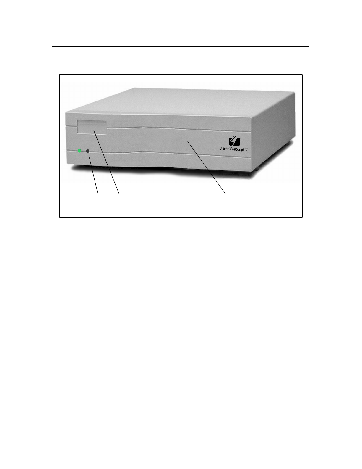
Controller The following illustrations give the location and
names of key parts of the controller:
1 2 3 4 5
Figure 1-1.4. Controller (front and right side view)
1. Left status light 4. Front panel bezel
2. Right status light 5. Side/top cover
3. Brand nameplate
4
Page 17
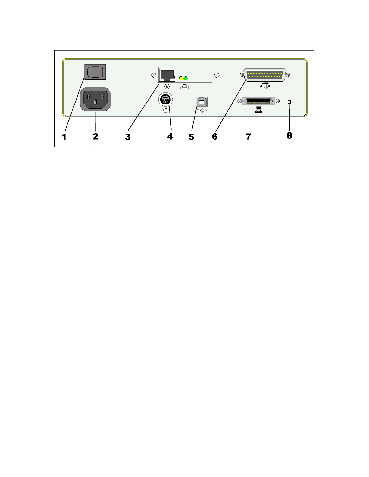
Figure 1-1.5. Controller (rear view)
1. ON/OFF power switch 5. Not supported
2. Power connector jack 6. Digital Duplicator port
3. 10BASE-T Ethernet LAN port 7. Bi-directional parallel (ECP) port
4. LocalTalk port (Apple Macintosh) 8. Diagnostic Test Page button
5
Page 18

6
Page 19

2
Using Your Controller
Introduction This chapter provides instructions on how to setup
and use your controller. It includes information
about:
q Connection Components.
q Setting Up Your Controller.
« A step-by-step process.
« Required memory.
« Print resolution.
q Installing a Printer Driver.
q Changing Printer Drivers.
q Automatic I/O switching.
q Connecting to a Peer-to-Peer Ethernet Local Area
Network.
q Managing Paper.
« Page size and orientation.
« Number of copies.
« Bleed-off printing.
q Shared Printer Environments.
« Using a switchbox.
« I/O port order.
« Optimizing multiple I/O port operation.
« Personality/language switching.
q Managing Print Jobs
« The Configuration Utility program.
« Starting the Utility.
« Canceling a print job.
« Optimizing operation in a shared printer
environment.
Caution Proper Grounding: Ensure that all interface cables
and host computer(s) or other equipment attached to
the controller follow proper grounding methods for
electronic equipment in accordance with local
electrical codes.
7
Page 20
Connection Components
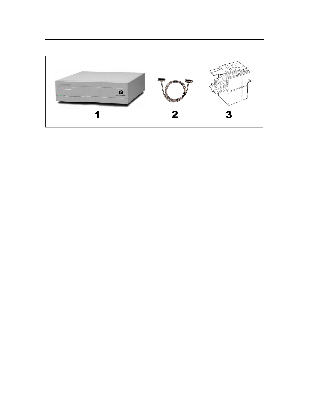
Figure 2-2.1. Major Components
The three major components are:
1) Controller. Several models are available which
will work with your digital duplicator. Its
function is to make the digital duplicator appear
as a printer to a computer. As such, it provides
one or more physical connection ports for a
computer, formats the documents sent by a
computer for printing on the digital duplicator,
and houses built-in fonts.
2) Cable for the digital duplicator-to-controller
connection. This cable is shipped with the
controller and provides the communication path
between controller and digital duplicator.
3) Digital Duplicator. Various models exist, each
one unique in its characteristics and
specifications. The function of the digital
duplicator is to make the physical master and
copies.
8
Page 21

Setting Up Your
Controller The process of setting up your controller is extremely
easy and straightforward.
A step-by-step
Process Follow the simple steps below to have your product
printing documents in a very short time.
Network Note If you are in the process of installing the controller/
digital duplicator on your computer as a printer
accessible though a local area network (LAN), and
the controller and digital duplicator have been
previously set up using the procedure outlined by the
steps in this section, you may skip this section and
proceed to the section in this chapter entitled
Installing a Printer Driver.
If the controller/digital duplicator are to be used as a
network printer, but have not been previously setup
using the procedure outlined by the steps in this
section, you must follow the steps outlined in this
section first, then proceed with installation as a
network printer.
Caution Power OFF the digital duplicator before proceeding
with the setup steps that follow.
9
Page 22
Step 1
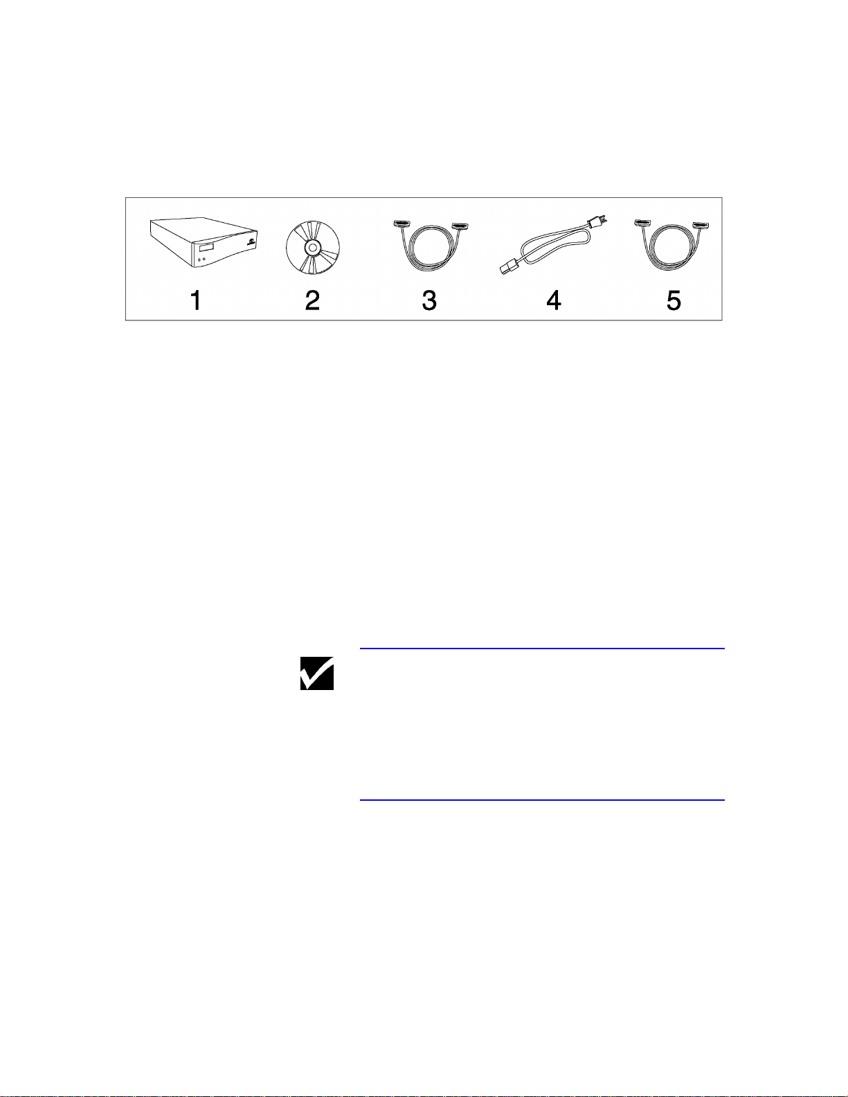
Unpack the Controller There are five items (shown in Figure 2-3.1)
contained in the controller shipping box.
Figure 2-3.1. Items contained in the shipping box.
1. Digital duplicator controller.
2. CDROM containing the Configuration Utility
software, drivers, and controller documentation.
3. Controller-to-digital duplicator communications
cable - DB25M connector to DB25F connector.
4. Power cord for the controller.
5. Computer-to-controller communications cable -
DB25M connector to IEEE 1284C MiniCentronics connector.
Unpack all items and set on a table near the digital
duplicator.
Note The shipping container for the controller is designed
specifically to protect the controller and other
components from being damaged during shipment.
We recommend that you store the box in a safe place,
from where it may be retrieved and used should you
need to return the controller for service.
10
Page 23
Step 2
Locate a Place to
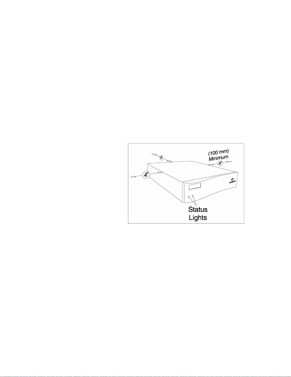
Keep the Controller The controller must be set up within 6 feet (2 meters)
of the digital duplicator. This is the length of the
cable between the two units.
The controller may be mounted in any position or
direction. The only constraints are:
1) Leave a minimum or 4 inches (100 mm) between
the back panel, left and right side panels and any
other object for proper ventilation,
2) If possible, mount the controller in a position
where the computer operator may clearly see the
front panel status lights.
Figure 2-3.2.1. Controller Ventilation
Requirements
11
Page 24
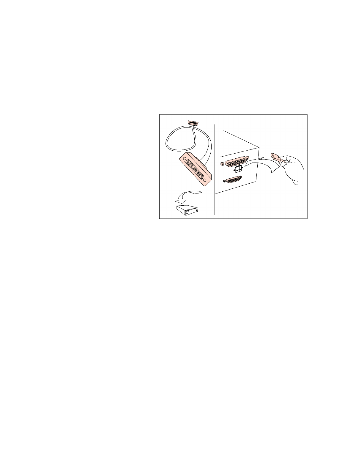
Connect the Digital
Duplicator to the
Controller Use the cable supplied with the controller to connect
Step 3
the controller’s digital duplicator port to the controller
port on the digital duplicator.
.
Figure 2-3.2.2. Connecting the Controller to
the Controller-Digital Duplicator Cable
12
Page 25
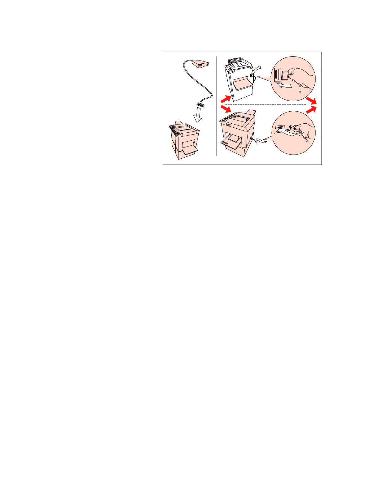
Figure 2-3.2.3. Connecting the Digital
Duplicator to the Controller-Digital Duplicator
Cable
Your digital duplicator will have one or the other of
the following types of controller connections.
The vertical connection is typically located on the
side of the digital duplicator.
The horizontal connection is typically located on the
back of the digital duplicator.
13
Page 26
Step 4
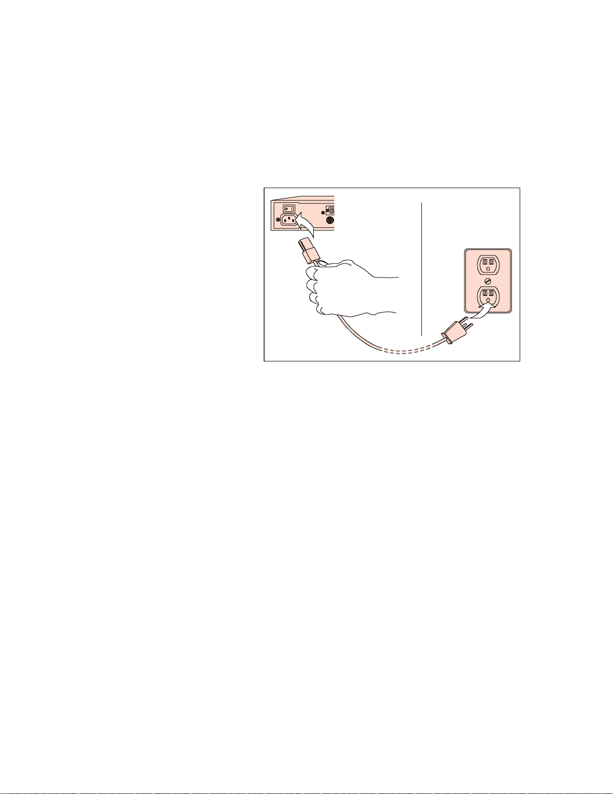
Connect Power to
the Controller Locate the power cord which came with the
controller, and attach it to the controller’s power input
jack, and a local mains power socket (can be the same
supply as is used for the digital duplicator).
Figure 2-3.3.1. Connect Power to the
Controller
14
Page 27
Step 5
Apply Power to the
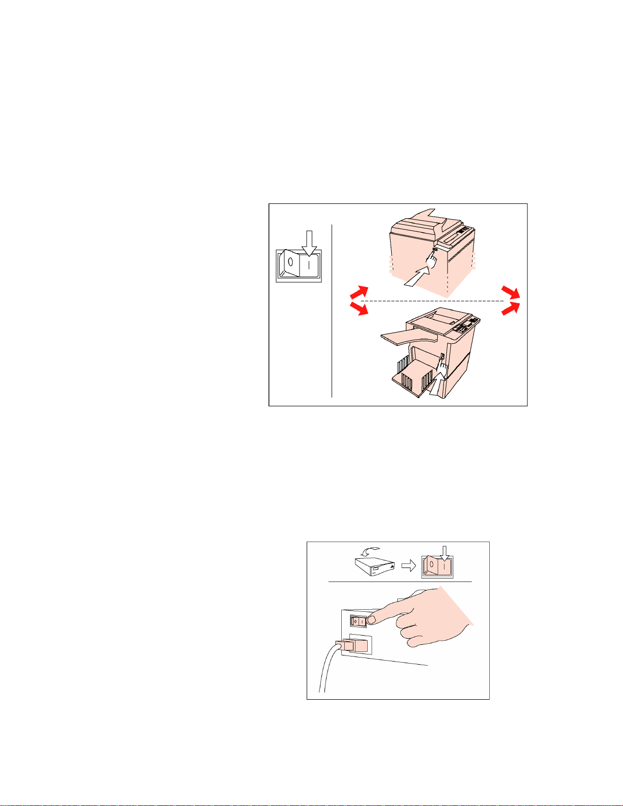
Digital Duplicator Power ON the digital duplicator by locating the
power switch and pushing it to the ON (“1”) position.
The switch is usually located in one or the other of
the positions indicated by the drawings in Figure 2-
3.3.2.
Apply Power to the
Controller Power ON the controller by locating the power switch
Figure 2-3.3.2. Power On the Digital
Duplicator
Step 6
and pushing it to the ON (“1”) position.
Figure 2-3.3.3. Power On the Controller
15
Page 28
Step 7
Put the Digital
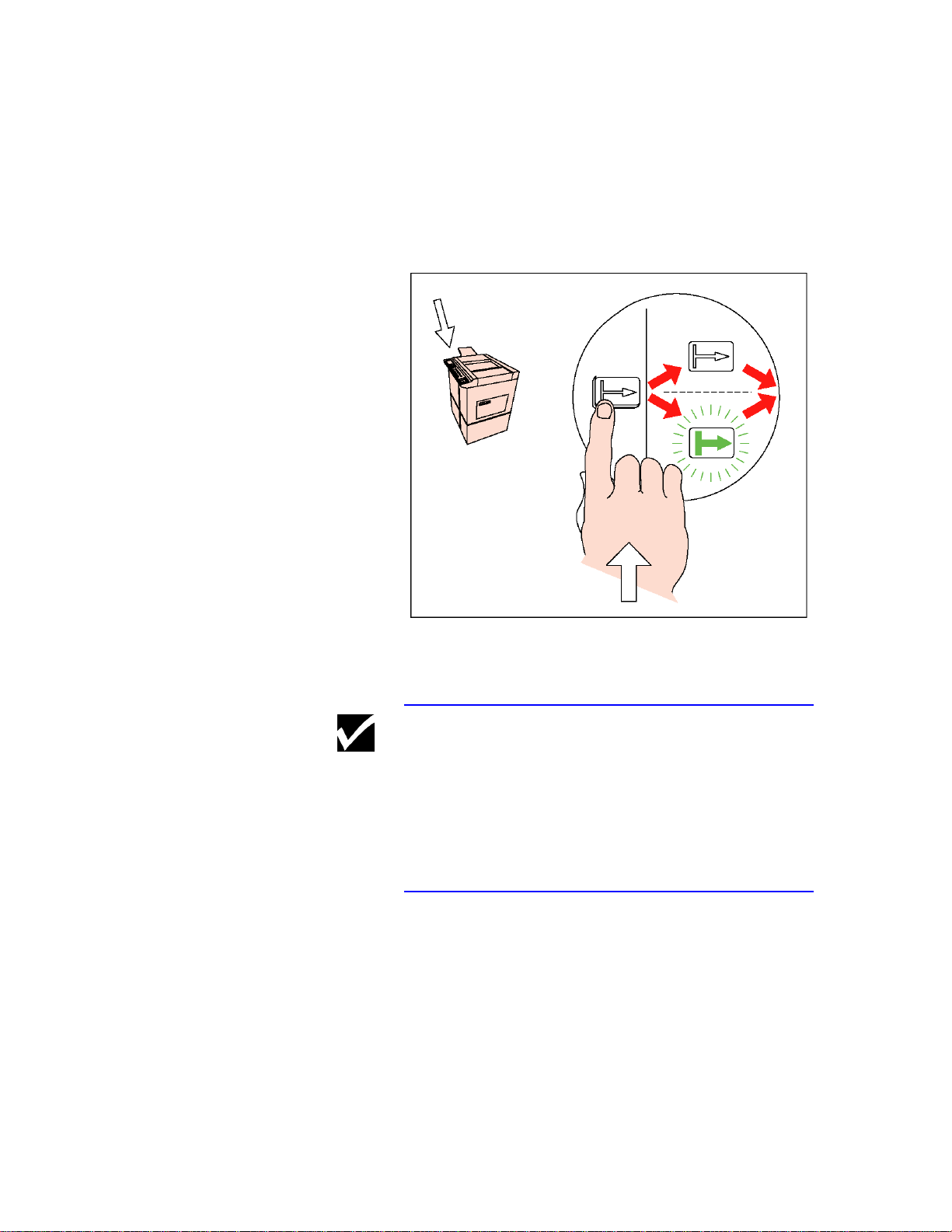
Duplicator ONLINE Locate and push the ONLINE button on the digital
duplicator.
Figure 2-3.3.4. Push the ONLINE button on
the Digital Duplicator
Note The ONLINE symbol or light may or may not
illuminate when the button is pressed. Even though
the action of pushing the ONLINE button enables
communication with the controller, some models of
digital duplicators will illuminate the lamp only after
a print job has been sent.
16
Page 29
Check for Controller
Green Light Status
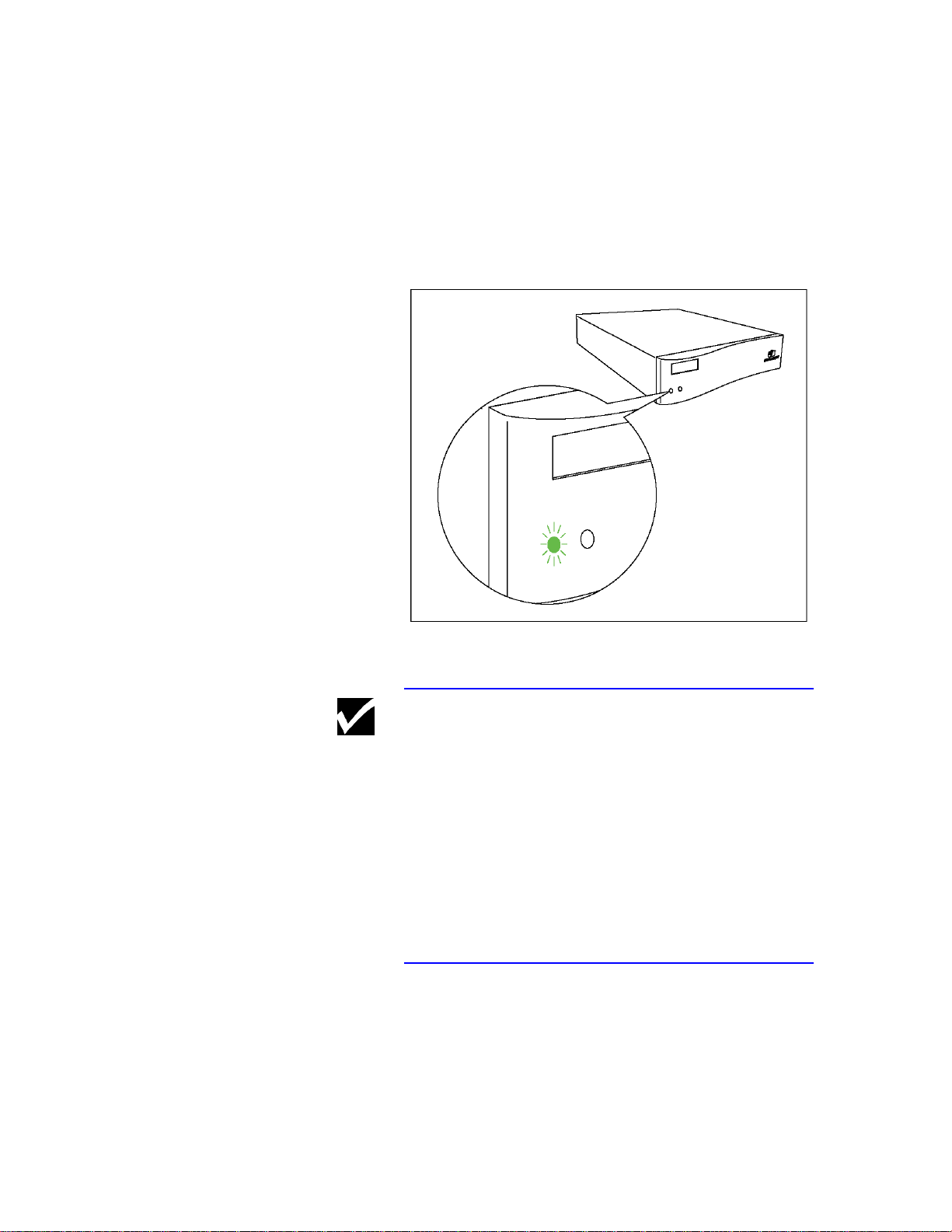
Step 8
Locate and observe the status lights on the front panel
of the controller. If the digital duplicator is ONLINE
and it and the controller are functioning properly, the
left status light should be green and on steady.
Figure 2-3.4.1. Controller Green Light Status
Note If the controller begins flashing error messages (red
or yellow lights), either the setup has not been done
correctly or there is a problem with the digital
duplicator or controller. DO NOT PROCEED with
the remainder of this setup procedure until the
problem has been resolved.
For assistance, look in Chapter 7, Troubleshooting, or
Appendix B, Controller Status Lights, for assistance.
If the problem persists, contact the supplier of your
digital duplicator.
17
Page 30
Print a Diagnostic
Test Page
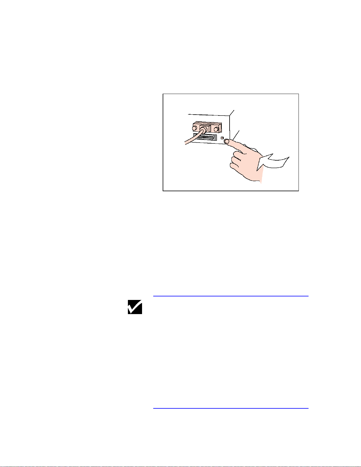
Step 9
Locate and push the Diagnostic Test Page button on
the rear of the controller.
Figure 2-3.4.2. Push the Diagnostic Test
Page Button
The digital duplicator will make a master and print a
page similar to the one shown in Figure 2-3.4.3.
This process confirms that the controller and the
digital duplicator are communicating correctly. The
exact contents of the Diagnostic Test Page do not
matter at this point – we are only confirming that the
controller and digital duplicator are functioning
together.
Note If the controller or digital duplicator begin flashing
error messages, or you do not get a test page printed
from the digital duplicator, either the setup has not
been done correctly or there is a problem with the
digital duplicator or controller. DO NOT PROCEED
with the remainder of this setup procedure until the
problem has been resolved.
For assistance, look in Chapter 7, Troubleshooting, or
Appendix B, Controller Status Lights, for assistance.
If the problem persists, contact the supplier of your
digital duplicator.
18
Page 31
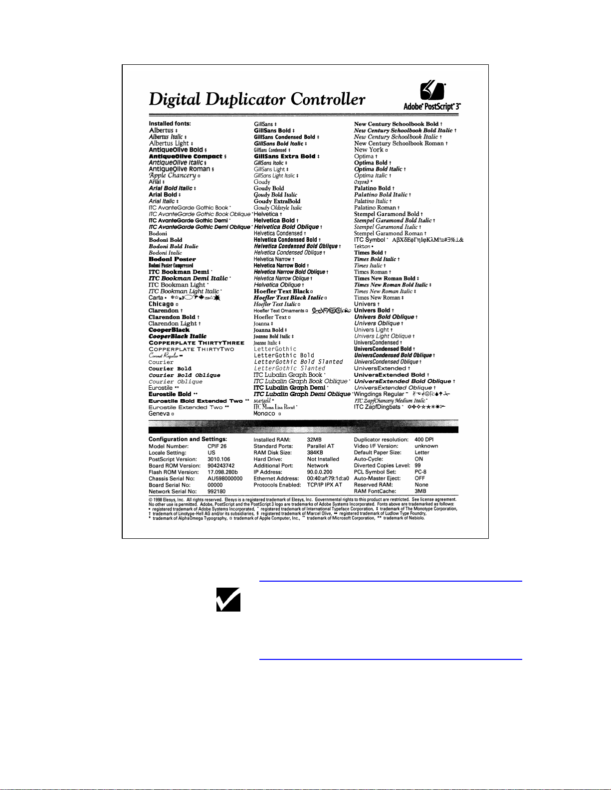
Figure 2-3.4.3. Diagnostic Test Page (sample)
Note The contents of the Configuration and Settings:
section of the page will depend upon your particular
controller and digital duplicator combination.
19
Page 32

Connect Your
Computer to the
Controller Locate the parallel port on the back of the controller
Step 10
and attach an appropriate parallel cable between it
and the parallel output port of your computer.
Figure 2-3.5.1. Connect your computer to the
controller’s parallel port
Note To facilitate the setup procedure, the initial
connection between the PC and the controller is done
at the parallel port. After the setup of your controller
is complete, connection of the computer to the
controller may be done at any of the other ports.
20
Page 33

Load the CDROM into
Your Computer Locate and install the CDROM that came with the
Step 11
controller into your computer’s CDROM drive.
Figure 2-3.6. Load the CDROM into your
computer.
21
Page 34

Step 12
Install the
Configuration
Utility software Once the CDROM has been loaded into your
computer, it will be necessary to locate and start the
Configuration Utility installation program:
a) Start Windows Explorer and open the CDROM
directory,
b) Locate and double-click on the SETUP.EXE
filename.
Screens will appear prompting you for answers to
questions regarding your digital duplicator in order to
install it as a printer for your computer.
22
Figure 2-3.7. Configuration Utility
installation.
Page 35

Required Memory The amount of memory required for printing with
your controller has been predetermined and installed
in the controller. No additional memory is required.
However, additional memory may be installed to
enhance your controller’s job loading and master
creation speeds, to increase its soft font download
capacity, or both. See Upgrading Controller Memory
in the appendix of the Controller Reference Manual,
for details.
Print Resolution The resolution of the printed output is the same as the
specification for your digital duplicator.
23
Page 36

Installing a Printer
Driver The Configuration Utility installation program on the
CDROM that came with your controller provides a
very intuitive, screen-by-screen installation process of
the:
• Configuration Utility program,
• Printer drivers for your model of digital duplicator
and controller,
• User’s Guide,
• Reference Manual, and
• LAN administration tools.
Note Correct installation of the Configuration Utility,
printer drivers, manuals and other software assumes
the controller/digital duplicator have been setup
previously following the procedure outlined in the
section entitled Setting Up Your Controller, in this
chapter. If this is not the case, you must first follow
the steps outlined in that section before proceeding.
24
Page 37

Network Note If controller/digital duplicator are being installed on
this computer as a printer accessible through an
Ethernet local area network (LAN), and the controller
is not currently connected to the computers parallel
port, do the following (assuming the controller/digital
duplicator are already setup and functioning on the
LAN):
1) Follow the steps outlined here, ignoring any
warning messages you receive regarding the
computer not being able to communicate with the
controller/digital duplicator.
2) Skip any steps relating to generating a test page.
3) After completion of the installation steps, proceed
to the section in this chapter entitled Connecting
to a Peer-to-Peer Ethernet Local Area Network.
25
Page 38

After inserting the installation CDROM,
c) Start Windows Explorer and open the CDROM
directory,
d) Locate and double-click on the SETUP.EXE
filename.
A screen similar to Figure 2-4.3 should appear.
Figure 2-4.3. Starting the CDROM installation
program.
As shown in Figure 2-4.3, the first screen asks you to
select your language. Select the desired language and
click on .
The installation program is user-friendly and will
guide you through a series of steps to complete the
installation.
When complete, the necessary components for using
the digital duplicator through the printer port of your
computer will be installed, along with the Controller
User’s Guide and the Controller Reference Manual.
26
Page 39

Note To determine the model number, look on the outside
bottom your controller chassis. There is a small label
containing a bar code affixed to the chassis near the
rear panel, similar that shown in Figure 2-4.4.
MODEL NO. CPIF 26
S/N: AU1234567891234567891
AU123456789
Figure 2-4.4. Model and serial number label.
27
Page 40

Changing a Printer
Driver Most of the time you will probably stay with one
printer driver for your digital duplicator. This is
because your software will use either PCL or
PostScript fonts. For example, if your desktop
publishing program uses primarily PostScript fonts,
you will want to use the PostScript printer driver for
your controller so you maintain WYSIWYG (‘whatyou-see-is-what-you-get’) compatibility between your
screen and the printed output. However, if you
switch to a different program, such as a spreadsheet
which uses PCL fonts, you will need to change printer
drivers to keep your screen and printed outputs
similar.
Changing to a different printer driver to match the
requirements of your software is very easy. The
following example is given for Microsoft Word 97,
but is similar for most programs that run under the
Microsoft Windows operating system. In this
example, we are changing from PostScript to PCL.
First, locate and activate the Print menu in your
software.
Figure 2-5.1.1. Locate your software’s Print
screen (example is Microsoft Word 97).
In the example shown in Figure 2-5.1.1, we are
currently using the PostScript 3 driver for a digital
duplicator. To change this to the PCL driver for the
same digital duplicator, click on the down arrow next
to the printer name field to bring up all of the choices.
28
Page 41

Figure 2-5.1.2. Selecting a different printer
driver.
Select/highlight the PCL version of the same digital
duplicator (as shown) by clicking on it once, then
select the OK tab on the bottom right of the screen.
In this example, the controller will automatically be
set to PCL mode to print the document, allowing the
screen and printed fonts to match.
29
Page 42

Automatic I/O
Switching Any your controller’s three I/O ports – LAN,
LocalTalk, and bi-directional/ECP parallel – may be
used at the same time. This allows you to attach
cables to all ports and communicate to all ports from
up to three host computer systems (see Figure 2-6.1).
Your controller will automatically switch between
ports to accommodate incoming data. This allows
you to think of each port as a separate controller.
Figure 2-6.1. Automatic I/O Switching Ports
A = LAN (hub), B = LocalTalk (Apple Macintosh), C
= ECP parallel (PC)
30
Page 43

Note Bi-directional/ECP parallel is backwards-compatible
with Centronics parallel standard. Although it uses
the same cable, hardware, and software as Centronics
parallel, to receive its enhanced capabilities – such as
bi-directional communication between computer and
controller, faster transmission of data, and autoconfiguration of printer drivers – you need software
that supports these features. Most Windows software
supports these features. However, if in doubt, check
with your software vendor to see if your software
supports bi-directional/ECP parallel features.
Automatic I/O switching can be adjusted for optimum
performance using the Controller Timeout value. If,
when using multiple ports, data from other ports
appears in the middle of your print job, increase the
value of this variable. For more information, see
Controller Timeout value under Managing Print Jobs,
Optimizing operation in a shared printer
environment, in this chapter.
Caution Proper Grounding: Ensure that all interface cables
and host computers attached to the controller follow
proper grounding methods for electronic equipment in
accordance with local electrical codes.
31
Page 44

Connecting to a Peerto-Peer Ethernet
Local Area Network Your controller can be attached directly to a peer-to-
peer, Ethernet-based Local Area Network, or LAN,
using the instructions outlined here. Any PC
connected to the network, once configured, may print
to the digital duplicator.
Network Note These instructions:
1) Assume the controller/digital duplicator have
already been set up though a computer’s parallel
port and function correctly so connected. If this is
not the case, you must return to the Setting Up
Your Controller section of this chapter and
complete the installation before proceeding.
2) Assume one or more printer drivers for the
controller/digital duplicator already exist on your
computer, set up to print through the parallel port
(LPT1:). If this is not the case, you must go to the
Installing a Printer Driver section of this chapter
and complete the procedure before continuing.
3) Apply to workstations only (not servers) on a
‘server-less’, peer-to-peer network. If your
network uses a server, if you do not know if your
network has a server, or if you are attempting to
setup a network server to use the controller,
contact your network administrator for assistance.
Instructions for network administration are found
in Chapter 4, User Administration, of the
Controller User’s Guide.
4) Assume that if you are on an NT4 workstation,
you have administrator privileges.
To enable printing to a controller/digital duplicator
from a network workstation on a server-less, peer-to-
peer LAN, follow the steps outlined in this section.
32
Page 45

Connect the Ethernet
LAN to the controller.
Step 1
Figure 2-7.1. Connecting to a LAN.
Locate the 10BASE-T LAN port on the back of the
controller, as shown in Figure 2-7.1. Using a
standard UTP (Unshielded Twisted Pair) Ethernet
cable, attach one end of the cable to this port on the
rear of the controller, and the other end to your
Ethernet network drop (LAN port jack on the wall or
floor, or to your LAN hub).
Network Note If you are unsure as to where the network drop/
connection is located for your office LAN, contact
your network administrator for assistance.
33
Page 46

Step 2
Configure your
computer to talk to
the controller over
the network. On your Windows desktop, locate the Network
Neighborhood icon, and click the right mouse
button. Click on Properties. Then click on the
Protocols tab. A screen similar to Figure 2-7.2 will
be displayed.
34
Figure 2-7.2. IPX/SPX protocol installation.
In order to communicate with the controller over the
network you must have the IPX/SPX protocol
installed on your computer. If this is not the case, it
must be installed before proceeding with IPX port
installation.
Page 47

Network Note If the IPX/SPX protocol is not installed on your
computer, you can install it using the instructions
contained in the Windows Help function (Start →
Help), clicking on the Index tab, and entering
protocols, installing into the field. Follow the
instructions for installing the IPX protocol.
If you are unsure as to whether the protocols are
installed on your computer, or do not wish to install
them, contact your network administrator for
assistance before proceeding further.
Step 3
Restart your
computer.
Step 4
Turn off all
applications running
on your computer. This includes word processing and spreadsheet
programs, and especially any programs that use the
network (web browsers, etc).
35
Page 48

Note You may skip Step 5 and Step 6 and proceed to Step
7 if the controller has been powered on for 2 minutes
or more.
Step 5
Power on the
digital duplicator,
then the controller.
Step 6
Wait until the
controller is ready to
receive data from the
LAN. Allow the controller to be powered on for at least 2
minutes before continuing.
Network Note It is necessary to wait for 2 minutes whenever power
is first applied to the controller, in order for it to
complete its internal power-up process. However,
once the controller has gone through its power-up
process, it will accept data from the network at any
time.
36
Page 49

Locate and install the
IPX Redirector
Program.
Step 7
This program installs an IPX ‘port’ for the controller
(similar in concept to your parallel or serial port, but
software only) into your computer. The program
actually searches for the controller through the
network, identifies it using the controller’s network
serial number, then creates and installs a port for it
into your Windows Printer Wizard.
The IPX redirector program is installed from the
CDROM supplied with your controller. To do this,
go to Start → Run. If the CDROM in your
computer is assigned drive letter e:, you would type
the following information into the ‘Open’ window:
e:\WIN\LAN Tools\IPXP2P\setup
followed by the Enter key. The setup installation
wizard will begin and you will be presented with a
screen similar to Figure 2-7.3.
Figure 2-7.3. IPX Redirector program setup.
Follow the instructions to completion.
37
Page 50

Step 8
Restart your
computer again.
Step 9
Attach the digital
duplicator printer
driver to the IPX port. Double-click on My Computer and open the
Printers folder. Right-click on the digital duplicator
printer driver (installed earlier) you wish to attach to
the network port, click on Properties, and select the
Ports tab. In a few seconds the ports screen will
open.
38
Figure 2-7.4.1. Attach the digital duplicator
printer driver to the desired IPX port.
Examine the Print to the following port: field. It
will be similar to what is shown in Figure 2-7.4.1.
Page 51

In our example, we have a PostScript 3 (PS3) printer
driver for our digital duplicator already installed on
our computer. It is currently attached to the LPT1:
printer/parallel port (performed during the initial
setup described under Installing a Printer Driver, in
this chapter).
In the list under the Port menu item appears the term
OTS_992180,
and under the Description menu item appears
(OTS Ethernet Option).
These two terms identify the IPX LAN printer port
assigned to the controller by the IPX Redirector
program. The 992180 number in the port name is
the network serial number of the controller, while the
(OTS Ethernet Option) character string identifies
it as being an active, IPX-protocol port. Note that,
since it is the only name of this type appearing in the
list, it is the only controller on the LAN visible by our
computer.
In order to print to the digital duplicator over the
LAN we must ‘attach’ our PS3 printer driver to this
IPX port. To do so, simply click on the box next to
the OTS_ port to make a check mark appear in it.
This action detaches the printer driver from the
computers parallel port and attaches it to the IPX
LAN port.
When finished, select the button. The
Ports screen should then appear similar to the
example in Figure 2-7.4.2.
39
Page 52

Figure 2-7.4.2. An IPX LAN printer port
‘attached’ to the printer driver.
If you exit and re-enter the Properties for this printer
driver, it should appear as shown on Figure 2-7.4.3,
with the printer driver name under the Printer
column.
40
Page 53

Figure 2-7.4.3. Finished IPX port installation.
41
Page 54

Network Note The IPX Redirector program installs an IPX port for
every controller/digital duplicator it finds attached to
the LAN. Thus, if more than one controller is
attached to the LAN, you will have multiple IPX
network names/ports from which to choose. You may
confirm you have selected the correct IPX network
name by verifying that the
1) controller’s network serial number matches the
number in the IPX LAN printer port name, and
that the
2) digital duplicator model to which the controller is
connected matches the printer driver with which
you are working.
The network serial number of the controller in
question may be identified using the Diagnostic Test
Page generated by it (see Appendix A, Diagnostic
Test Page, in the Controller User’s Guide). The
number is located in the lower left corner of the page.
The OTS_992180 character string of the IPX LAN
printer port name is also the NetWare Print Server
Name. A network administrator may change it to
another more readily identifiable name, such as Sales
Digital Duplicator, or the actual name/model of the
digital duplicator. See Assigning a custom name to
the controller under the section entitled Using a Web
Browser to Perform Common Network Management
Tasks in Chapter 4, User Administration, in the
Controller User’s Manual, for more details.
42
Page 55
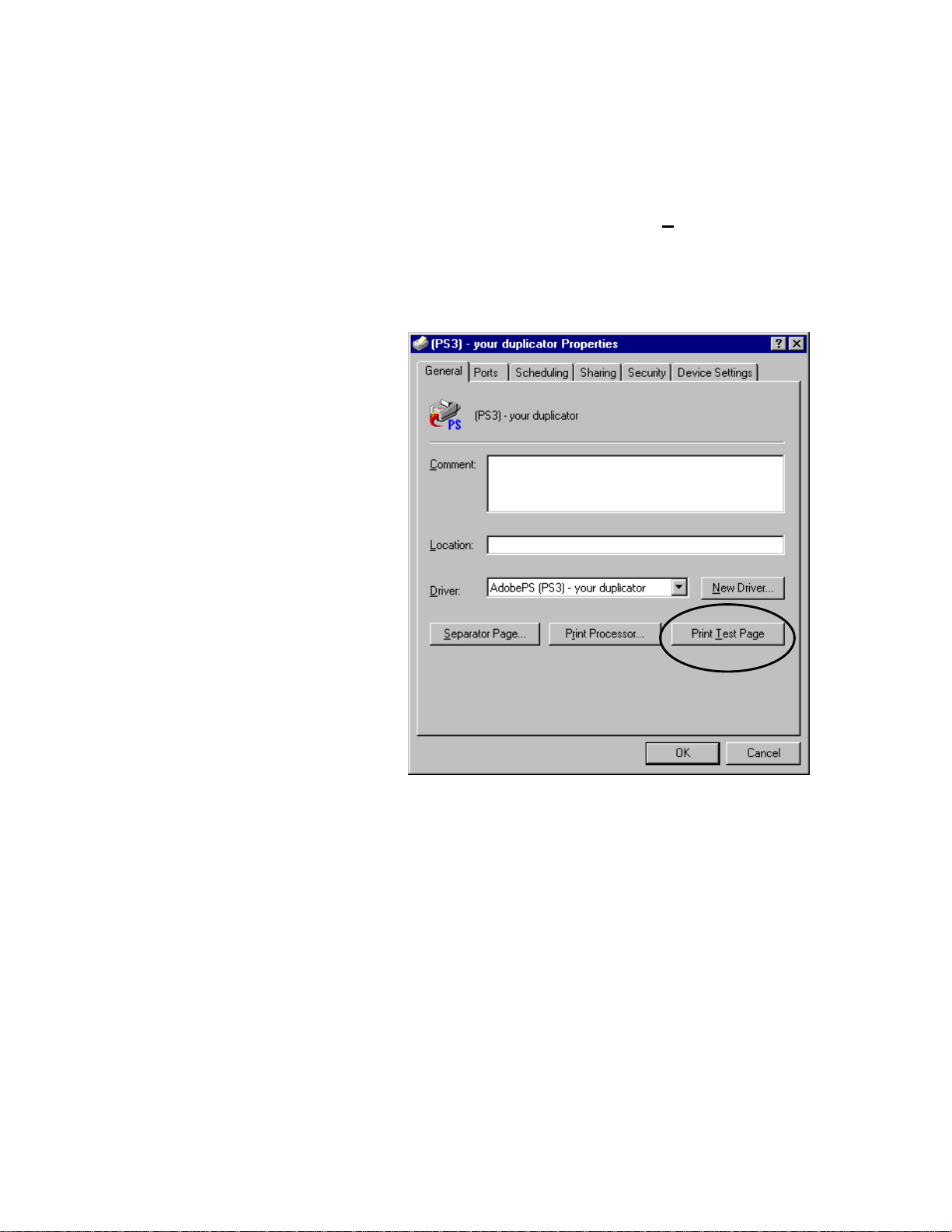
Print a Windows Test
Page. As shown in Figure 2-7.6, click on the General tab,
Step 10
then locate and click on the Print Test Page button.
In a few seconds to a few minutes (depending upon
how busy the LAN traffic is) the front status lights
should begin blinking, and the duplicator will print
the Windows Test Page.
Figure 2-7.6. Testing the LAN connection.
Correctly printing the Windows Test Page confirms
proper connection to the LAN and correct printer
driver installation.
43
Page 56

Troubleshooting The following suggestions may help if you run into
problems printing to the digital duplicator through the
LAN.
1) If there is more than one controller/digital
duplicator on the LAN, did you attach the printer
driver to the correct one? If not, go back and
repeat Step 8 and Step 9.
2) Is there a server on the LAN? Depending on the
type of server on the network, it may not allow
use of the IPX redirector program. In this case
you will need the help of your network
administrator to set up the workstation for
printing over the LAN to the controller/digital
duplicator.
3) Has any computer been able to print to the digital
duplicator correctly through the controller’s
parallel port? If so, the problem is probably with
the LAN installation, which will have to be redone - start by uninstalling the IPX Redirector
software (explained below), then go to Step 1. If
not, there may be a problem with the printer
driver you have installed. See the sections of the
Controller User’s Guide entitled Installing A
Printer Driver and Changing A Printer Driver in
Chapter 2, Using your Controller for assistance in
getting the correct printer driver installed on your
computer.
44
4) If the controller was off, or not powered on for 2
minutes or more, did you wait for the signal from
the LAN communications status lights before
installing the IPX Redirector program? The LAN
port on the controller is not active until the yellow
light begins blinking. If the IPX Redirector
program runs before this happens, it will most
likely not find the controller. Subsequently it will
not install an IPX port on your computer, and you
will not find it listed under ‘Print to the following
port:’ (see Step 9).
To correct this, re-do the IPX port installation.
Start by uninstalling the IPX Redirector software
(see below), then go to Step 1.
Page 57

Uninstalling the IPX
Redirector Software
5) Did you shut off all application software before
installing the IPX Redirector program? If not, it
may not have installed correctly, or a program
may be interfering with its operation. Try rebooting the computer. If that doesn’t work,
reinstall the IPX Redirector making sure to have
closed all application software (i.e., any program
except the Windows Operating System) before
installing again. Start by uninstalling the IPX
Redirector software (see below), then repeating
the installation from Step 1.
If you encounter problems installing or using the IPX
Redirector program, it may be uninstalled using a
utility provided for that purpose, found on the
CDROM.
To uninstall the IPX Redirector program, you must
insert the CDROM (e: in our example) do Start →
Run, and type the following into the ‘Open’ window:
e:\WIN\LAN Tools\IPXP2P\uninstall
followed by the Enter key .
Uninstalling will remove the IPX redirector program
as well as the port definition(s) from the Printer
Wizard’s list of available ports. Thus, you will no
longer be able to print to any digital duplicators on
the LAN using the IPX protocol of your computer.
45
Page 58
Managing Paper Take a few minutes to review the following sections
to understand how to effectively use the printing
capabilities of your controller.
Page size and
orientation For the most part, keeping track of the paper size and
orientation loaded into the digital duplicator paper
input tray is an automatic process for your controller.
If you remove, replace, or run out of paper, the digital
duplicator will go through a process to determine
what size paper is available and communicate that
information to the controller. Thus, your controller
automatically keeps track of what paper stock is
available for printing, and makes that information
available to the computer.
Be aware that anytime you remove paper from the
input tray, the digital duplicator will automatically go
OFFLINE. Then, when you send a print job to the
controller, the controller will set the digital duplicator
back ONLINE automatically1.
Note
1
You may have a model of digital duplicator that does
not allow the controller to automatically put it
ONLINE. If this is the case, you must manually push
the ON LINE and Auto-Cycle buttons to enable their
respective functions on the digital duplicator.
|→
46
Page 59

Table 2-8.1 lists common problems resulting from
page size mismatches, and their remedies.
Situation Probable Cause Remedy
The image on
the master is
truncated.
The image on
the master is
placed
incorrectly on
the page.
The software
you are using to
print never
reports a page
size mismatch.
A paper size too small
for the master has been
loaded into the input
paper tray.
The software is set up to
print on a smaller page
size than is currently
loaded in the input tray.
You are using one of the
standard printer drivers
that came with the
operating system.
Change the paper in the input tray of the
digital duplicator to match what the
software is calling for in order to print your
document. Then re-send the print job to
the controller.
You can print correctly-placed copies from
this master by doing the following:
1) Load the correct paper size into the
input tray.
2) Set the number of copies to be printed
manually using the keys on the digital
duplicator’s control panel
3) Push Print Start on the digital
duplicator.
Alternatively, you can load the correct
paper into the input tray and simply re-send
the print job from the computer.
Install the digital duplicator printer drivers
from the CDROM, then select the correct
one which matches your model of digital
duplicator.
Table 2-8.1. Common Page Size/Orientation Faults
47
Page 60

Number of copies The most effective way to make use of the digital
duplicator’s high-speed printing capabilities is to have
the controller manage the number of copies of each
page produced, rather than the word processing or
other computer software you may be using. This is
because the software will normally print multiple
copies of a document one at a time, a single page at a
time. This is referred to as collating the document
copies (the pages come out in numerical order, in
each document copy). This process causes the digital
duplicator to make a new master for each page.
Since the digital duplicator is designed to print many
copies of a page rapidly from one master, you will
need to turn the collate feature off in the software and
allow the controller to manage the copy creation
process.
The following two, simple steps will ensure that your
digital duplicator makes fast and efficient copies of
the documents you send to it from your computer.
48
Page 61

Step 1 – Make sure Auto-Cycle is ON
Normally the controller will turn this feature of the
digital duplicator ON1. Just to be safe, look at the
digital duplicator’s control panel and make sure
Auto-Cycle is ON.
The Configuration Utility program may be used to
have the controller enable the Auto-Cycle feature
automatically. Start the Configuration Utility and
locate the Settings section on the screen. Click on the
Enable Auto-Cycle circle, as shown in Figure 2-8.3.
The press the button.
Figure 2-8.3. Enable Auto-Cycle
1
See Note under the preceding section, Page size and
orientation.
49
Page 62
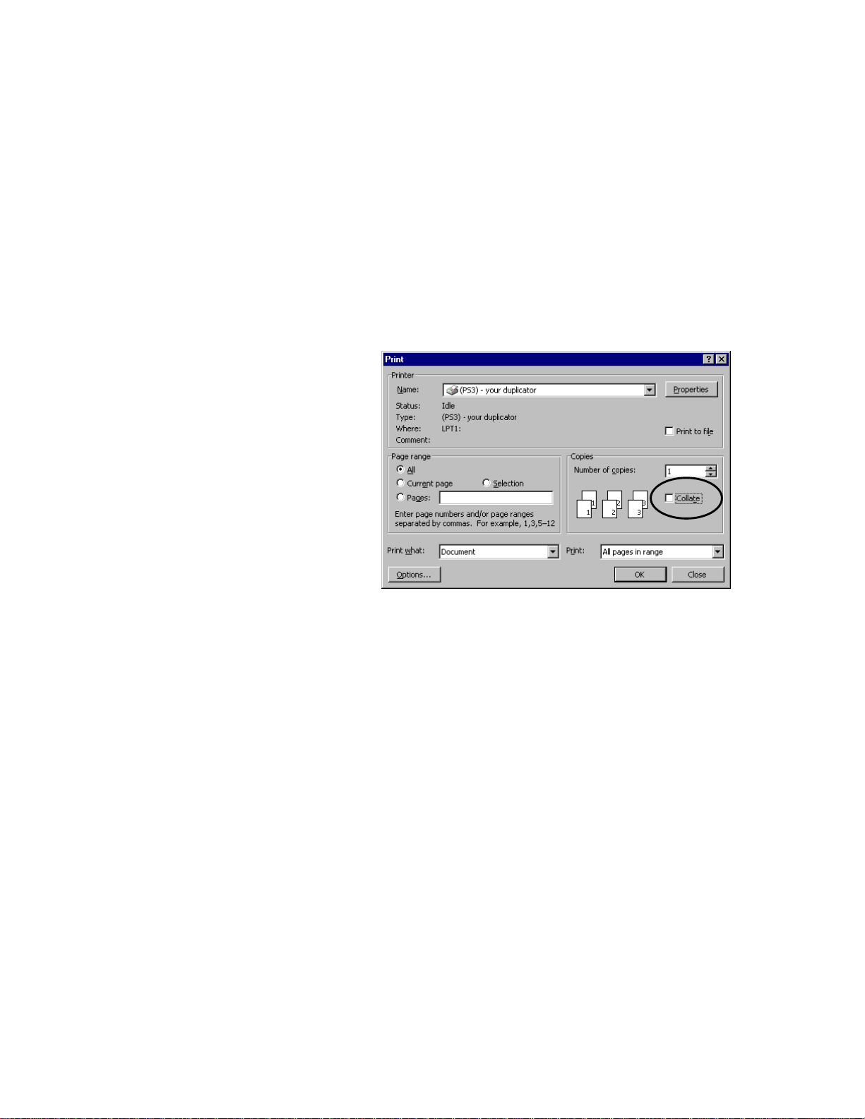
Step 2 – Turn the software collate
feature off
Most programs have an on/off switch for the collate
feature located on their print menu screen. In some
programs, this is referred to as ‘copies generated by
<software>’, versus ‘copies generated by printer’.
Turn the collate feature off. (For the Microsoft
Word 97 example in Figure 2-8.4 you would uncheck
the box, as shown.)
Figure 2-8.4. Turn the collate feature off
(Microsoft Word 97)
With the feature off, the digital duplicator will make
one master per page and produce the copies at a high
rate of speed, in a non-collated fashion, as it was
designed to do. In addition, the number of copies to
be printed will pass through from the software to the
digital duplicator, and be displayed on the digital
duplicator’s control panel screen.
50
Page 63

Note FOR DOS USERS:
Unless your DOS software application specifically
allows you to turn off the collating feature, passing
copy control (i.e., the number of copies) through to
the digital duplicator will not work properly. In this
case, you will have to send one page at a time from
the computer to the digital duplicator, and use the
control panel of the digital duplicator to manually
create the number of desired copies from each master.
51
Page 64

Bleed-off Printing Most desktop publishing programs allow printing to
the edges of the paper. You should be aware of the
following limitations as they apply to your controller
and digital duplicator regarding this function.
PostScript Printing
Due to the technology employed in the digital
duplicator for paper handling, there is a non-printing
area on the leading (first in) edge of the paper of
5mm.
PCL Printing
PCL printer driver technology does not allow bleedoff printing. Instead, you will have a border of
unprintable area of approximately .25 inches (6 mm)
on all four paper edges.
If you need to do the bleed-off function, use the
PostScript printer driver.
52
Page 65

Shared Printer
Environments You may wish to attach more than one computer to
your controller. Multiple ports have been provided
on the rear panel of the controller for this purpose see the section on Automatic I/O Switching above, in
this chapter.
This section lists several things to be aware of so that
operation between the computers and your controller
will run as smoothly as possible:
• Using a switchbox.
• I/O port order.
• Optimizing multiple I/O port operation.
Using a switchbox If you wish to share your digital duplicator through an
electronic or mechanical switchbox, you may
experience some difficulty under certain conditions,
particularly with mechanical switchboxes.
If you are using a mechanical switchbox:
• Do not switch when the controller is printing to
the digital duplicator, or receiving data (i.e., when
either of the controller status lights are blinking).
• Do not switch to a host computer that is OFF,
then switch that computer ON. The computer can
send unusable data to the controller, resulting in
unwanted output, or corruption of the next print
job.
Note Ensure that your switchbox is equipped with a surge
protector. Damage to the controller could occur from
use of unprotected mechanical switchboxes.
53
Page 66

I/O port order Print jobs arriving at the various ports are performed
(or Raster Image Processed – RIPped, for short) on a
first come, first served basis. Thus, the first computer
to begin sending data to the digital duplicator has the
controller’s full attention. Other computers must wait
until the first computer’s print job has completed.
Thus, even though the parallel port is the fastest one
to accept data, if the AppleTalk/LocalTalk port is the
first to be used, its job will complete before the one
coming from the parallel port.
Optimizing multiple
I/O port operation The Configuration Utility program may be used to
optimize the operation of your controller, so that
multiple computers may use the digital duplicator
efficiently. See the section in this chapter on
Managing the Print Jobs.
54
Page 67

Personality/
language switching You can select the print language – PCL or PostScript
– one of several ways, depending upon your operating
system software:
• For Microsoft Windows: select either a PCL or a
PostScript printer driver.
• For DOS: use context (automatic) language
switching, or PJL (Printer Job Language) software
switching (i.e., PJL commands embedded in
software).
Note When the controller’s personality is switched, its
memory is reconfigured, resulting in the loss of all
user-downloaded data (such as soft-font typefaces).
The result of this is that multiple print jobs with a
significant number of downloaded fonts can take
noticeably longer to process and print if the controller
keeps switching between PCL and PostScript, than if
it stays in one language.
Other than this longer processing time, changing print
languages is transparent to users because the software
simply re-downloads the fonts it needs.
Windows PCL and PostScript printer drivers
Both custom PCL and PostScript printer drivers are
available for your digital duplicator. Use the
installation program on the CDROM to install both of
the drivers. Then, in your Windows software, select
the printer driver on the Print menu screen you wish
to use. Personality switching will be accomplished
automatically when you send your print job to the
digital duplicator.
55
Page 68

Switching personalities in DOS programs
Context language switching is employed for PCL and
PostScript. In this mode, the controller analyzes the
stream of data being sent to determine which
language is being used by the print job. Then the
controller switches its personality to that language,
automatically.
As an example, if PostScript is made the current
language, the controller will be dedicated to that
language and will switch to another ‘personality’ only
when it encounters specific PJL commands embedded
in software to do so.
For more information about PJL commands, see the
PCL Printing chapter in the Controller Reference
Manual.
56
Page 69

Managing Print
Jobs Once a print job has been initiated by the software
you are using, it is offloaded to hardware or other
software set up to manage the printer. This process is
known as ‘spooling’. Programs that manage the
spooling process may exist in several places: 1) the
operating system of the computer you are using, 2) a
print server (such as on a network), or 3) the digital
duplicator’s controller.
Use the right tool to manage your print jobs.
If the job has been spooled by the operating system,
you should use a print management tool that came
with your computer’s operating system to manage
print jobs (e.g., Print Manager for Microsoft
Windows). Likewise for a network, there are a
number of tools your network administrator may use
to manage print jobs sent to printers attached to the
network.
57
Page 70

The Configuration
Utility Program The Configuration Utility program is used to setup
and manage specific aspects of the print jobs sent to
your digital duplicator. It has been designed to make
management of printing on your digital duplicator
very easy. By simply starting the program and using
your mouse, you may:
« Set operating parameters of your digital duplicator
specific to the needs of your environment.
« Manage printing to your digital duplicator in a
shared printer environment.
The Configuration Utility is very easy to start and
use. The steps below outline some of the
fundamental tasks associated with managing the use
of your digital duplicator and the print jobs sent to it.
Starting the Utility Activate the Configuration Utility program by
double-clicking on the Configuration Utility icon on
your computer’s desktop, as shown below.
58
Figure 2-10.2. Configuration Utility Desktop
Icon
Note If the icon shown in Figure 2-10.2 does not appear on
your computer’s desktop, look under Programs –
Configuration Utility. If it still does not appear, you
may need to run the CDROM installation program.
See the Setting Up Your Controller section of this
chapter, or contact your computer specialist for
assistance.
Page 71
Your computer will display the screen of the
Configuration Utility program, similar to what is
shown in Figure 2-10.3.
Figure 2-10.3. Configuration Utility screen
59
Page 72

The default value of the Controller Timeout is 45
seconds, which is adequate for the majority of
printing applications. However, some applications
may require a longer value. The reasons for this
could include (but are not limited to):
• An environment where most people are using
Windows-based, graphics intensive printouts that,
due to processing time, require the controller to
wait longer than 45 seconds to start receiving the
output.
In these cases it is recommended that the value of this
variable be set at 120 seconds or longer, to ensure
that the output from a second computer will not
disrupt the print job of the first.
For other tasks, see Chapter 3, Configuration Utility
Features.
60
Page 73

3
Configuration Utility Features
Introduction This chapter provides explanations for every function
available in the Configuration Utility program. It is
organized in order of the screen sections as they
appear from top to bottom, left to right.
Look in this chapter if you are interested in:
q Finding definitions of Configuration Utility terms.
q Understanding a Configuration Utility function or
feature.
To get an understanding of more general terms having
to do with printing and computers, see the Glossary at
the end of this book, located after the Appendices.
61
Page 74
Configuration Utility
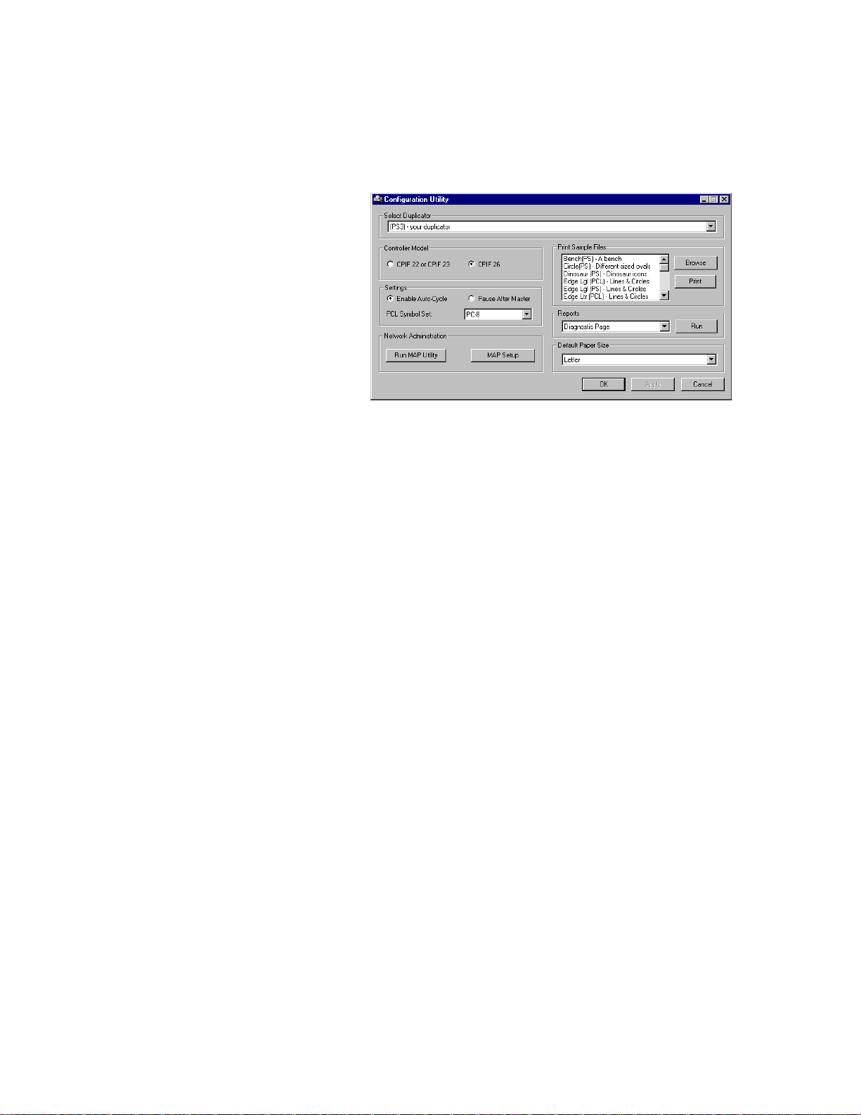
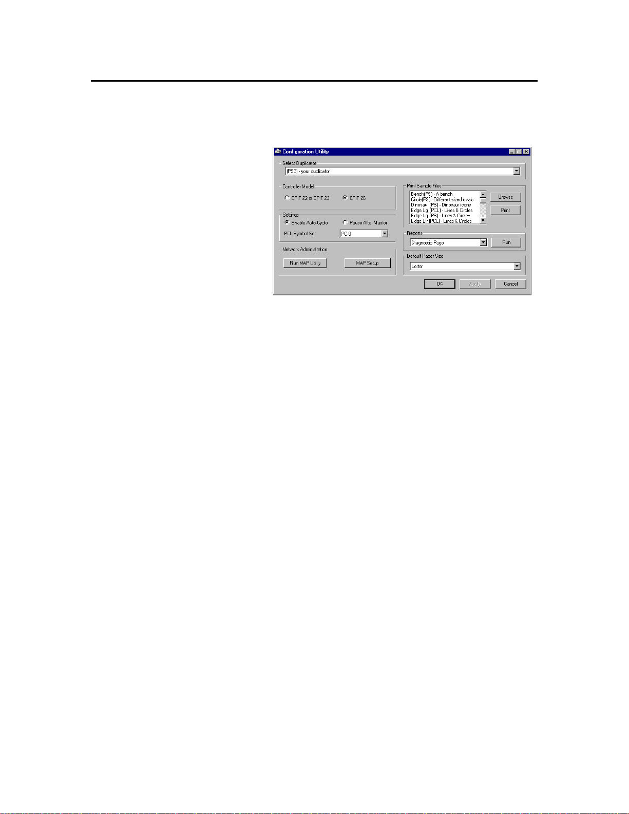
Screen After clicking on the icon, the Configuration Utility
screen in Figure 3-2.1 will appear.
Figure 3-2.1. Configuration Utility Screen
The Configuration Utility screen is divided into seven
sections. These are:
• The Select Duplicator selection screen,
• The Controller Model selection panel,
• The Settings selection panel,
• The Network Administration control panel,
• The Print Sample Files selection screen,
• The Reports selection screen,
• The Default Paper Size selection screen.
62
Page 75
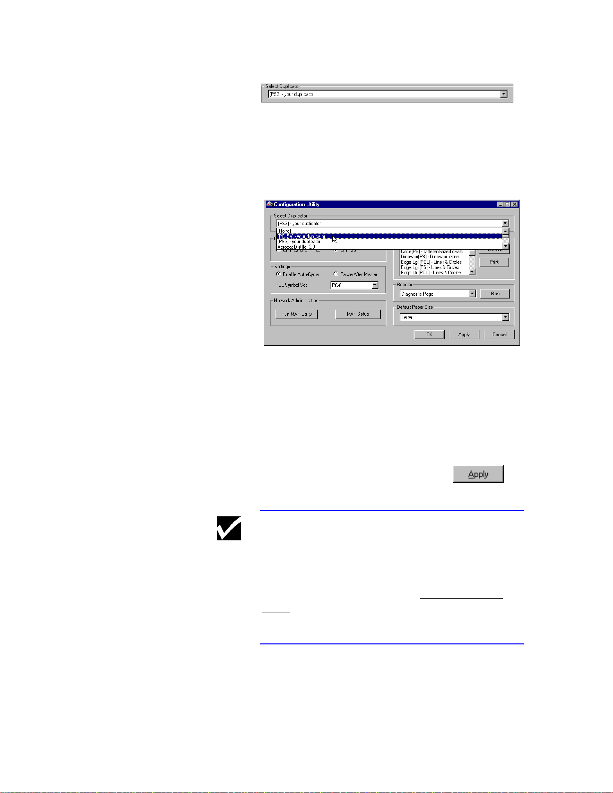
Select Duplicator
This feature is used to select the digital duplicator you
wish to configure.
To select a digital duplicator different from the one
that is being displayed, click on the down arrow at the
right of the display.
Figure 3-2.2.1. Selecting a digital duplicator
to configure.
A list of installed printer drivers will be shown.
Select the one corresponding to the digital duplicator
you desire to configure. After doing so, the selection
window will close, leaving the model of the digital
duplicator you selected in the window.
After making your choice, click on the
button to save the information
Note If the printer driver for your model of digital
duplicator does not appear as a choice on the screen,
it is likely that it has not been installed on your
computer. See Installing a Printer Driver in Chapter
2, Using your Controller, in this Controller User’s
Guide, for instructions regarding the installation of
printer drivers.
63
Page 76

Controller Model
This is where you inform the Configuration Utility as
to the model of controller connected to the digital
duplicator (see Select Duplicator above).
To determine the model number, look on the outside
bottom your controller chassis. There is a small label
containing a bar code affixed to the chassis near the
rear panel, similar that shown in Figure 3-2.3.
MODEL NO. CPIF 26
S/N: AU1234567891234567891
AU123456789
Figure 3-2.3. Model and serial number label.
After making your choice, click on the
button to save the information.
Settings
64
Enable Auto-Cycle or Pause After Master
This feature allows the controller to automatically
configure the digital duplicator for the mode of
master and subsequent copy making you wish to use.
If you enable Auto-Cycle, Pause After Master will be
disabled, and vice versa.
Page 77

PCL Symbol Set
Here you may select the symbol set to match the PCL
fonts your document is using. To select something
other than the default PC-8 symbol set shown, click
on the down arrow and select another from the
displayed list.
For a more complete discussion of which symbol set
to select, see Chapter 3, PCL Printing in the
Controller Reference Manual.
After making your choice, click on the
button to save the information.
65
Page 78

Network Administration
Discussion of the tools provided in the Network
Administration section (i.e., the Run MAP Utility and
MAP Setup functions), the resulting NIC HTML
screens and changing controller parameters is found
in Chapter 4, User Administration, and is oriented
toward the network administrator. Changing the
configuration of the controller’s LAN behavior to
optimize its operation in your LAN environment
requires particular knowledge and skills. In addition,
you need a password to access the LAN parameters,
which is set and kept by your network administrator.
Network Note If you are on a workstation operating in a server-less,
peer-to-peer LAN environment, it may possible to
setup and use the digital duplicator controller using a
relatively simple network installation. Read
Connecting to a Peer-to-Peer Ethernet Local Area
Network in Chapter 2, Using Your Controller, in this
Controller User’s Guide, to see if your situation
applies.
66
Page 79
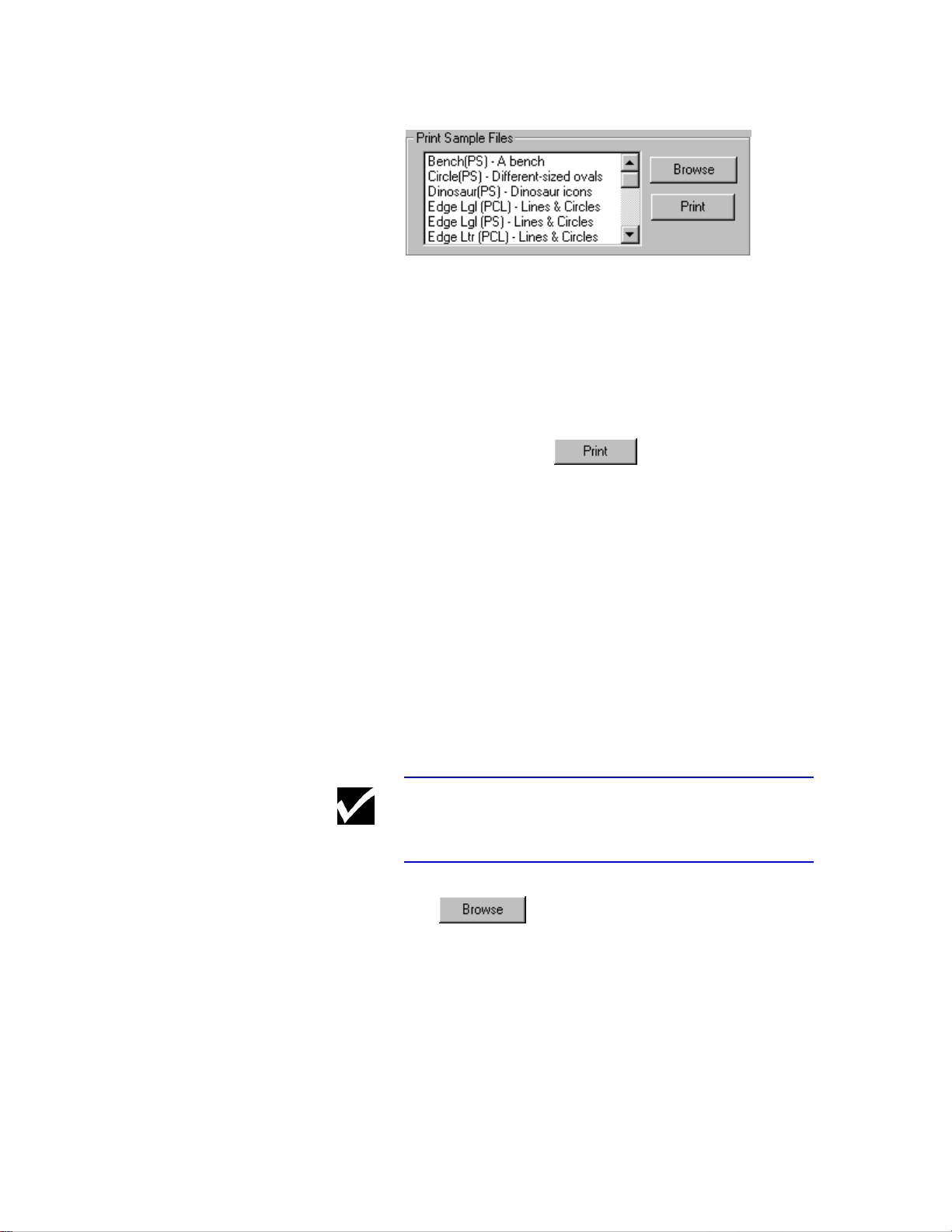
Print Sample Files
This feature allows you to print sample or raw test
files loaded on your computer. It is useful for
sending raw PCL or PostScript files to the digital
duplicator for printing, without having to use an
intermediate desktop publishing or word processing
software program.
Click on the file of interest in the window to highlight
it, then click on the button to immediately
send the file to the digital duplicator for printing.
You may also store your own custom files so they
appear in the directory shown above, by doing the
following:
1) Locate the PostScript file(s) you wish to have the
Configuration Utility add to the list above,
2) Store the files with a .PS extension into the
Samples folder inside the Configuration Utility
folder, on your hard drive.
The files will appear automatically in the Print
Sample Files directory Window.
Note The default location of the Configuration Utility
folder is the C: drive, inside the Program Files folder.
The button provides a convenient way to
access the files stored on your computer by opening a
simple file manager window. This window will allow
you to pick or find a printer file anywhere on your
computer, or (if installed) computer network, to send
to the digital duplicator for printing.
67
Page 80

Run Selected Report
The Reports section allows you to print a predesigned report selected from the pull-down menu,
appearing in the center. You may view the titles of
the available reports by clicking on the down arrow
on the right-hand portion of the menu.
The Diagnostic Page is the default report. Use this
report to print a Diagnostic Test Page on the digital
duplicator by clicking on the button .
This is the same page you would get if you were to
press the Diagnostic Test Page button on the rear
panel of the controller. For more information
regarding the Diagnostic Test Page, see Appendix A,
Diagnostic Test Page, in this Controller User’s
Guide.
Another report, the PCL Test Page, prints a list of
PCL fonts resident in the controller.
For more information regarding the PCL font list, see
Chapter 3, PCL Printing, in the Controller Reference
Manual.
68
Default Paper Size
Use this area to set the Default Paper setting.
Normally, the software you are using to print will
assign a paper size to a print job. Where this is not
the case, the controller must select a default size of
paper to associate with the print job. This is called
the Default Paper Size.
Select a default paper size by simply clicking on the
arrow on the right of the window and selecting the
desired size. After making your choice, click on the
button to save the information.
Page 81

User Administration
Introduction In this chapter we will discuss the aspects of
managing the controller and digital duplicator for
multiple users, where network print server functions
are being administered.
The subjects covered are:
q Using the Configuration Utility to Set Up Your
Network Controller.
« HTML setup screens.
« NIC Management Password.
« Setting NIC parameters.
q Using a Web Browser to Perform Common
Network Management Tasks
« Setting a custom NIC management password.
« Assigning a custom name to the controller.
4
q Network Environments and Special Utilities
« Common NOS environments.
« Special NIC management utilities.
« Preparing the controller.
« Common workstation configurations.
« NetWare notes.
« Windows notes.
« AppleTalk notes.
« NIC “Reset to Factory” procedure.
To get an understanding of more general terms having
to do with printing and computers, see the Glossary at
the end of this book, located after the Appendices.
69
Page 82

Network Note When working with the digital duplicator controller
from a network, you are actually communicating with
a Network Interface Controller, or NIC, card in the
controller. Keep in mind the following characteristics
of the card:
• Reset of the NIC and reset of the digital duplicator
controller are two different events: resetting the
controller also causes the NIC to reset (such as at
power up), while resetting the NIC from the LAN
only resets the card, and not the rest of the
controller hardware.
• Setting to factory defaults is only a NIC function,
and does not affect the rest of the hardware in the
digital duplicator controller.
• After reset or cycling power, the NIC enters a
warm-up state that lasts for approximately 2
minutes. Before the warm-up state of the NIC is
completed, you will not be able to communicate
with it.
The end of the warm-up state is signaled by the
digital duplicator printing a NIC Status Page, if
the Print Status Page on Startup parameter in the
NIC has been enabled. Otherwise, no status page
will print and the only way to tell if the warm-up
state has completed is by waiting 2 minutes or
more past a NIC reset or power up.
• Setting parameters on the NIC are only stored into
non-volatile memory after cycling power on the
controller.
70
Page 83

Using the
Configuration Utility
to Set Up Your
Network Controller The digital duplicator controller will operate in a
variety of network environments. In order to have it
do so efficiently, the Network Interface Controller
card, or NIC, in the digital duplicator controller must
be configured for the type of network on which it will
be used.
The easiest way to configure the NIC is to use the
Network section of the Configuration Utility screen.
The MAP utility, which is invoked by the buttons in
this section, automatically finds any controller in
most LAN environments. This provides the network
administrator a tool for rapidly configuring the NIC
parameters to suit the LAN environment.
The MAP utility uses two different protocols to
‘discover’ the controller: IPX and IP.
IPX/IP discovery
After the prescribed warm-up time, a NIC set to
factory default status (i.e., where NetWare is enabled)
will always respond to the IPX discovery MAP
routine using an IPX/SPX identifier. This is in the
form of ‘NPS_abcdef’, where ‘NPS_’ identifies the
unit as a network print server, and abcdef is the
network serial number of the controller.
The IPX discovery utility is part of the MAP function
and is automatically invoked whenever the
button is pushed. After pushing this
button, the computer’s default web browser is started,
and, if they are found by MAP, one or more
controllers will be listed in the order of IPX network
name. By clicking on the subsequent hyperlink
displayed on the screen, the web browser may be used
to query the NIC, inspect or change parameters, etc.
The MAP discovery routines will also find a
controller if NetWare is not enabled, as long as the
controller has an IP address. If no IP address has
previously been assigned to the NIC, then MAP can
only identify the controller through the IPX protocol.
71
Page 84

MAP
The Management Access Program, or MAP, is the
tool the Configuration Utility calls upon to discover
controllers on the network. In its default state, MAP
uses both IP and IPX protocols to discover the NIC.
You may configure MAP to have it not run one or the
other protocol. To do so, click on the
button
MAP responds with its setup screen, which you may
use to enable or disable the desired protocol.
Figure 4-2.1.2. MAP Configuration
Max Hops for IP Search sets the number of
routers through which MAP will search.
72
Page 85

Other Tools
Several tools have been provided on the CDROM
delivered with your controller to assist you in
configuring it for your network. Which one(s) you
use will depend upon your network environment and
the method you chose to do the job. A more complete
discussion on this topic is covered in a later section
entitled Network Environments and Special Utilities,
in this chapter.
HTML setup screens Subsequent to starting the MAP utility from the
Network section on the Configuration Utility screen,
the computer’s default web browser opens. Upon
finding of one or more controllers on the network,
you will see a screen similar that shown in Figure 4-
2.2.1.
Figure 4-2.2.1. NIC discovery
In this particular instance, MAP has ‘discovered’ one
controller, which happens to have a valid IP address
assigned. It displays the network serial number and
IPX/SPX identifier of each controller found.
73
Page 86

Network Note The controller’s default IPX network name (begins
with ‘OTS_’ - see Step 8 under Connecting to a Peerto-peer Ethernet Local Area Network in Chapter 2,
Using Your Controller, in the Controller User’s
Guide) and permanent IPX/SPX identifier (begins
with NPS_’ – discussed in this section) both utilize
the network serial number of the controller.
Hyperlinks on the page allow you to select the desired
controller for network configuration. Subsequent
HTML pages are sent from the selected NIC in
response to clicking on the hyperlinks in the text.
Upon selecting a controller to configure, the NIC will
respond with a Printer Status web page. Ignore the
information on this page, and double-click on the
Network Configuration hyperlink.
The NIC will respond with its HTML Network
Administration web page, similar to what is shown
in Figure 4-2.2.2.
74
Figure 4-2.2.2. NIC Network Administration
page.
Page 87

NIC management
password The default password for network administrator NIC
The actual display you receive may differ slightly,
depending upon the characteristics of your PC
monitor, the revision of firmware in the NIC, and
your default browser. In addition, options available
to the Network Administrator as displayed on this
page may change with any NIC firmware upgrades, to
provide greater control over NIC parameters and
control new functions.
management, as shipped from the factory, is:
sysadm .
All functions accessible through the HTML screens
are password protected. This is necessary to prevent
untrained or unauthorized users from changing vital
controller network parameters. Before beginning the
process of configuring the controller, it is
recommended that the network administrator set this
password to something other than the default version.
The next section, HTML setup screens, lists the area
available to customize this password. The password
may be up to eight (8) characters in length. Once a
new password is entered, the sysadm default
password will be rejected by the NIC.
75
Page 88
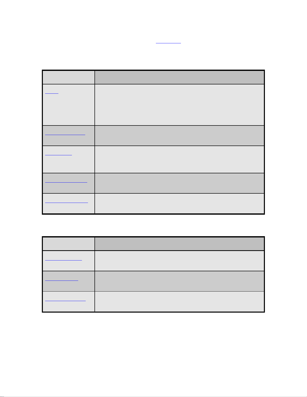
Setting NIC parameters Using the hyperlinks on the NIC HTML page, the
user-configurable parameters and controls include
those listed in Tables 4-2.3.1 through 4-2.3.3, below.
Option Action
Reset Performs a hardware reset of the NIC only (not the controller).
Used to bring the NIC back to the beginning of its power up
routine. If Print Status Page on Startup is enabled, the NIC
will produce a Status Page signaling its readiness to receive data,
usually 2 minutes or less after the Reset occurs.
Factory Defaults Sets all NIC (LAN) parameters back to their original factory
settings, including the NIC management password.
Unit Status A single screen listing the current configuration of each of the
controllers three network protocols - NetWare, TCP/IP, and
AppleTalk.
Network Address A screen displaying the network serial number of the controller, and
the Ethernet hardware network (MAC) address of the NIC.
Change Password Provides an area to change the system administrator’s password.
The default password from the factory is sysadm.
Table 4-2.3.1. Network Administration Options – System Area
Option Action
Setup NetWare The screen used to set all parameters relating to a NetWare LAN
topology.
Setup TCP/IP The screen used to set all parameters relating to a TCP/IP LAN
topology.
Setup AppleTalk The screen used to set all parameters relating to an AppleTalk
(EtherTalk) LAN topology.
Table 4-2.3.2. Network Administration Options – Protocols Area
76
Page 89

Option Action
Test Printer Causes the controller to immediately print a NIC Test Page on the
digital duplicator, using PostScript or ASCII. A sample NIC Test
Page appears in Figure 4-2.3.1.
Configure Status
Page
Printer Status Displays a screen showing the printer (controller) status, any errors
Table 4-2.3.3. Network Administration Options – Others Area
Tells the controller whether or not to print a NIC Status Page to the
digital duplicator, using PostScript or ASCII, on power up. You
may also immediately print a Status Page using this screen. A
sample NIC Status Page appears in Figure 4-2.3.2.
that have been detected, and any messages from the printer
(controller).
Caution Be careful setting the configuration of the
controller’s network operation.
If the controller should somehow lose its capability to
communicate to the network using any protocol, the
NIC will have to be set back to factory default status
using the hardware jumpers on the card, before
network operation can resume. This procedure is
called “Reset to Factory”, and is reserved for a
trained, service technician.
77
Page 90

Figure 4-2.3.1. Sample NIC Test Page
(PostScript).
Figure 4-2.3.2. Sample NIC Status Page
(PostScript).
78
Page 91

Using a Web
Browser to Perform
Common Network
Management Tasks In all likelihood, several parameters of the controller
will have to be customized in order for it to function
in your network environment. This section outlines a
couple of the more common tasks which either must
or will be performed, regardless of what kind of
network you have.
Network Note These procedures assume the controller is in factory
default configuration.
Setting a custom NIC
management password. This should be one of your first tasks as a network
administrator in order to prevent tampering with the
controller’s parameters.
The password may be accessed using 1) the NIC’s
HTML pages via a web browser, or 2) using the
Windows Telnet function. The latter method requires
the controller to have a TCP/IP address, which in the
factory default configuration has not been assigned.
As long as the controller has its NetWare protocol
enabled (which is a factory default condition), it will
always respond to the MAP utility’s IPX discovery
routine. This, therefore, is the preferred method,
which is outlined below.
1) Start the Configuration Utility, go to the Network
section and click on the button to
begin the search for controllers.
2) Select the one of interest, identifying it by the
network serial number.
3) On the Network Administration page under the
System column, locate and click on Change
Password.
79
Page 92

4) Enter sysadm in the Old Password field, then
up to 8 characters in the New Password field,
followed by re-entering the same characters into
the ReType New Password field.
5) Click on the button. The
new password will now be accepted, and the
default password of sysadm will no longer be
accepted.
Caution Be careful setting and remembering the NIC
management password.
Should you forget or lose the management password
the NIC will have to be set back to factory default
status using the hardware jumpers on the card, before
management of controller network operation can
resume. This procedure is called “Reset to Factory”,
and is reserved for a trained, service technician.
Once this procedure is performed, or if you invoke
the Factory Defaults HTML page, the NIC
management password will be set back to the factory
default value of sysadm.
Assigning a custom
name to the controller. This task can greatly facilitate setup of the digital
duplicator as a printer on a workstation. By assigning
a name to the controller other than its default serial
number, the IPX printer port can be more readily
identified with the correct printer driver. This will
reduce calls for assistance in doing peer-to-peer
workstation printer configuration.
A functioning IPX LAN printer port name consists of
two parts:
a) the NetWare Print Server Name : the factory
default string is “OTS_123456”(where 123456
is the controller network serial number), followed
by
b) an IPX-protocol-active identifier: always
(OTS Ethernet Option).
80
In the factory default configuration, the NetWare
protocol in the controller is enabled (allowing the
Page 93

controller to communicate using IPX protocol), and
the NetWare Print Server Name is the default string.
If you set the NetWare Print Server Name, for
example, to ‘Sales Digital Duplicator’ or the actual
make/model of your digital duplicator, it will be
reported as part of the IPX LAN printer port name in
place of the default string. This can facilitate the
process of identifying the controller port to which you
want to attach the printer driver, making setup easier.
The following steps outline an example of how this is
done.
1) Start the Configuration Utility, go to the Network
section and click on the button to
begin the search for controllers.
2) Select the one of interest, identifying it by the
network serial number.
3) On the Network Administration HTML page,
under Protocols, locate and click on Setup
NetWare.
4) Locate the Print Server Name: field. Enter a
name. Some reasonable entries might be the
model of digital duplicator to which the controller
is attached, or the location of the digital
duplicator. In our example, we chose to do the
later – Marketing DD.
5) Enter your password in the field appearing below
the warning at the bottom of the page,
A password is required to perform this
function.
then press .
6) Cycle power on the controller, or perform the
Reset function under the System column on the
Network Administration page. After warm-up,
the controller will respond to the IPX Redirector
program with the new NetWare Print Server
Name.
Figure 4-3.1 shows how the port choices might appear
on the Details screen of the printer driver properties,
once this change has been made.
81
Page 94

Figure 4-3.1. Custom IPX LAN printer port
name.
Note that the IPX LAN printer port name still includes
the term
(OTS Ethernet Option),
identifying it as an active, IPX-protocol port.
Network Note If one or more digital duplicator installations have
been done prior to this installation, several IPX LAN
printer port names may be visible. ONLY those
names that include the IPX-protocol-active identifier
of (OTS Ethernet Option) are active, functioning
ports.
To reduce confusion, it is suggested that any other
controller ports whose names do not include this
identifier be eliminated from the list using the
key of the Details screen.
82
Page 95

Network
Environments and
Special Utilities
Several fundamental network environments are
covered in this section, along with suggested methods
of communicating with the controller.
Network Note On any Windows 95, Windows 98, or Windows NT
workstation, the Configuration Utility may be used in
lieu of other software to make the necessary changes
to the controller’s network configuration, and is much
faster and easier.
Some of the utilities discussed in this section are part
of your operating system. Folders containing the
others are stored in the C:\ Program Files\
Configuration Utility folder on your hard drive, and
on the CDROM that came with your controller, as
follows:
[Configuration Utility]:\LAN Tools ,
[CDROM drive letter]:\WIN\LAN Tools .
Common NOS
environments.
Novell NetWare
••
♦ Versions 2.x, 3.x, 4.x
♦ Bindery-based and NDS systems
•• Windows 95/98 peer-to-peer
♦ LPD/LPR over TCP/IP
•• Windows NT
♦ Versions 3.5, 3.51, 4.0
♦ LPD/LPR over TCP/IP
•• AppleTalk
83
Page 96

Special NIC
management utilities. Table 4-4.1.1 outlines additional utilities are provided
on the CDROM, or were included with your
operating system.
Utility Workstation OS Protocol Used to …
MAP Windows1 95/98/NT IPX, IP … Discover the NIC, then
invoke a web browser to read
the HTML setup pages from
the NIC. The HTML pages
allow changes to all NIC
parameters.
IPX Redirector Windows1 95/98/NT IPX … Create an IPX printer port
on the workstation assigned
to the controller.
IP Redirector Windows1 95/98/NT IP … Create an IP printer port
on the workstation assigned
to the controller.
BootP Windows1 95/98/NT IP … Set IP parameters - IP
address, subnet mask, default
gateway.
ARP, RARP,
PING
Windows2 95/98/NT IP … Set and verify NIC IP
address.
Telnet Windows2 95/98/NT IP … Change IP parameters,
disable protocols,
enable/disable banner pages,
restore to factory defaults,
change NIC management
password, reset the NIC.
NIManage MAC OS 7.6.1
1
AppleTalk … Change AppleTalk
parameters, disable other
protocols, enable/disable
NIC status page.
1
Stored on the CDROM.
2
Included with your operating system.
Table 4-4.1.1. Special NIC Configuration utilities
84
Page 97

Network Note
Preparing the
controller. Prior to beginning work on setting up the network
•• Use of the BootP, ARP and RARP utilities
requires knowing the Ethernet Address (also
termed the MAC address) of the NIC.
•• The NIC must be in its factory default state to use
BootP, RARP, or PING.
•• After the NIC has an IP address, the Telnet or
MAP utilities may be used to change IP address,
subnet mask, or the default gateway.
•• MAP requires that an Internet web browser be
installed on the workstation.
configuration of the controller, confirm that
communication is taking place between it and the
digital duplicator by generating a Diagnostic Test
Page. If you are not able to generate the page,
perform the 12 step setup process outlined in the
section entitled Setting Up Your Controller, located in
Chapter 2, Using Your Controller, in the Controller
User’s Guide.
On the bottom of the Diagnostic Test Page, highlight
or otherwise make note of the following three items:
•• Network Serial Number: the serial number of the
NIC card inside the controller.
•• Ethernet Address: the hardware or MAC (Media
Access Control) address of the NIC card inside
the controller.
•• IP address. If it exists, it was either assigned
manually or by a DHCP server prior to this
installation.
Power down the controller and install an Ethernet
cable between it and a network drop.
85
Page 98

Common workstation
configurations. The following tables list some common workstation
and solutions for the NetWare and Windows NOS
environments.
NOS Version Protocol NOS Configuration Utility NIC Configuration Utility
NetWare 2.x IPX/SPX PConsole version 3.75 MAP version 3.50
NetWare 3.x IPX/SPX PConsole version 3.75 MAP version 3.50
NetWare 4.x IPX/SPX PConsole version 4.15 MAP version 3.50
Table 4-4.1.2. NetWare Workstation Configurations
Workstation
OS
Windows
NOS,
Protocol
NT
95/98
Windows NT*NT
Windows
95/98/NT
Windows
95/98/NT
*
versions 3.5, 3.51, 4.0
*
*
P2P,
TCP/IP
P2P,
IPX/SPX
Table 4-4.1.3. Windows Workstation Configurations
Printing
Method
*
LPR spooler LPR Shareware LPR Spooler:
Configuration
Utility
Printer Port Configuration
* Remote Host = [NIC IP address]
* Remote Printer = PORT 1
*
LPR spooler LPR
NT provides its own LPR Spooler
Configuration
IP Peer-to-Peer IP Peer-to-Peer
Redirector
software
Add a Printer Wizard:
* Set up as a local printer
* Port = [NIC IP address] @ 10001
IPX Peer-toPeer
IPX Peer-to-Peer
Redirector
software
Add a Printer Wizard:
* Set up as a local printer
* Port = Ethernet Option
86
Page 99

NetWare notes.
NetWare 2.x and 3.x. PConsole.
1) Start PConsole and select the File Server you
want to use.
2) Create the Print Queues under the Print
Queue Information option.
3) Specify the NIC as a Print Server under the
Print Server Information option.
4) Assign the Print Queues by choosing the
Queues Serviced by Printer option.
5) Setup the Notify option by choosing Notify List
for Printer under the Print Server Config
menu, and select the printer from the Defined
Printers List.
6) Repeat steps 1 through 5 for each additional File
Server.
NetWare 4.x Bindery Emulation.
1) Go to the 4.x server and at the system console
type: load install
2) Select Maintenance/Selective Install from the
menu.
3) Select NCF Files Options from the menu.
4) Select Edit AUTOEXEC.NCF from the menu.
5) Search the file for the following statement:
SET BINDERY CONTEXT = 0U = ENG
substituting your own file server context in place
of =0U=ENG .
6) At the console prompt, type the same SET
BINDERY CONTEXT statement that you just
entered in the AUTOEXEC.NCF file.
The command at the console prompt takes effect
immediately. The definition in the file takes effect
when the server is shut down and then restarted.
87
Page 100

Configuring Print Server and Queues with
PConsole for Bindery or NDS (bindery
emulation) Modes.
1) Log into the network as ADMIN and type
PConsole.
2) [if you are using NDS bindery emulation, go to
Step 3] The AVAILABLE OPTIONS menu will
appear. Press the F4 key for BINDERY MODE.
3) Select Quick Setup. Use Quick Setup to
correctly connect your print server, print queue
and printer.
4) Select Print Server and press the F3 key to
modify the entry. Enter the name of the print
server in the Print Server field and press Enter.
5) Press the ESC key to move to the New Printer
field. Type in a name and press Enter.
6) Press the ESC key to move to the New Printer
Queue field. Type in a name and press Enter.
7) Press the ESC key to move to the New Printer
Type field, and press Enter. From the list of
Printer Types, select Other/Unknown and
press Enter.
8) When finished, press the F10 key to save the
configuration.
88
 Loading...