

Page 1

OPCs
(Organic Photoconductors)
RICOH CO., LTD.
October, 1995
Page 2

Table of Contents
1. OUTLINE. . . . . . . . . . . . . . . . . . . . . . . . . . . . . . . . . . . . . . . . . . . 1-1
2. COMPOSITION AND FUNCTIONS . . . . . . . . . . . . . . . . . . . . . . 2-1
2.1. Composition . . . . . . . . . . . . . . . . . . . . . . . . . . . . . . . . . . . . . 2-1
2.2. Function and Material of Each Layer . . . . . . . . . . . . . . . . . . 2-1
3. STYLES . . . . . . . . . . . . . . . . . . . . . . . . . . . . . . . . . . . . . . . . . . . 3-1
3.1. Drum and Belt. . . . . . . . . . . . . . . . . . . . . . . . . . . . . . . . . . . . 3-1
4. COPY CYCLE . . . . . . . . . . . . . . . . . . . . . . . . . . . . . . . . . . . . . . . 4-1
4.1. Overview. . . . . . . . . . . . . . . . . . . . . . . . . . . . . . . . . . . . . . . . 4-1
4.2. The Steps of the Copy Cycle . . . . . . . . . . . . . . . . . . . . . . . . 4-2
5. OPC CHARACTERISTICS . . . . . . . . . . . . . . . . . . . . . . . . . . . . . 5-1
5.1. General Characteristics . . . . . . . . . . . . . . . . . . . . . . . . . . . . 5-1
5.2. Special Characteristics. . . . . . . . . . . . . . . . . . . . . . . . . . . . . 5-2
5.2.1. Deterioration in OPC Thickness . . . . . . . . . . . . . . . . . 5-2
5.2.2. Wavelength of Light. . . . . . . . . . . . . . . . . . . . . . . . . . . 5-3
5.3. Differences between Analog and Digital OPCs . . . . . . . . . . 5-4
6. EFFECTS OF ENVIRONMENTAL FACTORS . . . . . . . . . . . . . . 6-1
6.1. Light . . . . . . . . . . . . . . . . . . . . . . . . . . . . . . . . . . . . . . . . . . . 6-1
6.2. Temperature . . . . . . . . . . . . . . . . . . . . . . . . . . . . . . . . . . . . . 6-1
6.3. Gases . . . . . . . . . . . . . . . . . . . . . . . . . . . . . . . . . . . . . . . . . . 6-2
6.4. Dust and Oil . . . . . . . . . . . . . . . . . . . . . . . . . . . . . . . . . . . . . 6-2
Page 3
October 1st, 1995 OUTLINE
1. OUTLINE
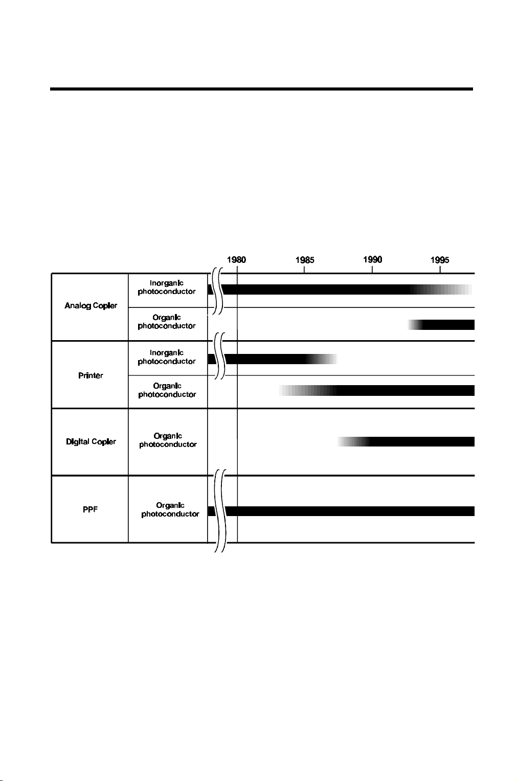
In most copiers or plain paper facsimile machines, a photoconductor transfers
an image of the original to the output of a printer.
Generally, our products use two types of photoconductors. One type is an inorganic photoconductor, made of selenium, that was used in the past for
analog copiers. The other type is an organic photoconductor (OPC) that is
used for analog and digital copiers, plain paper facsimiles, and laser printers.
Recently, all such products use OPCs instead of inorganic photoconductors.
1-1
OPC507.wmf
Page 4
October 1st, 1995 COMPOSITION AND FUNCTIONS
Composition
2. COMPOSITION AND FUNCTIONS
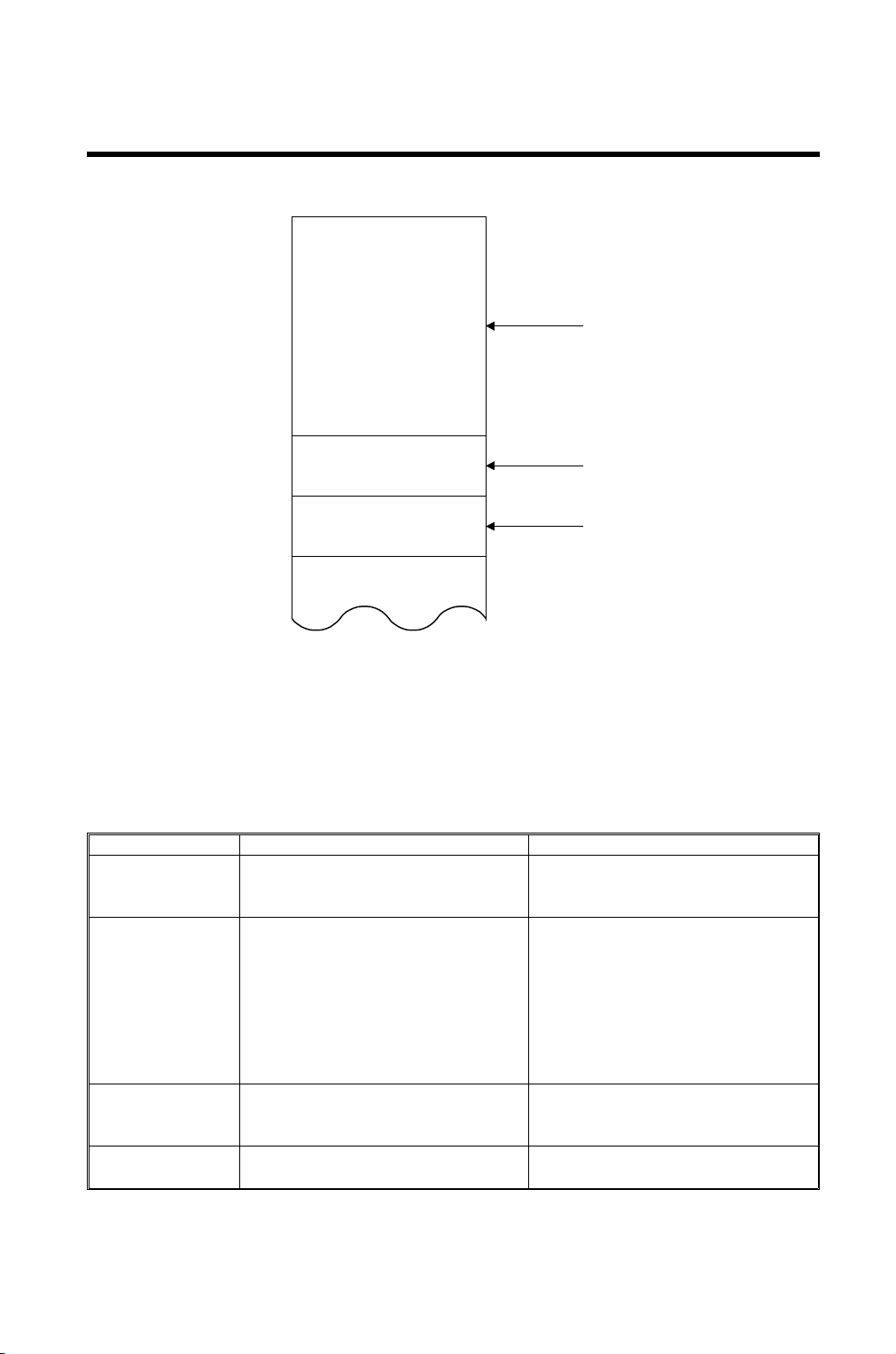
2.1. Composition
CTL
(Charge Transfer Layer)
(Charge Generation Layer)
CGL
UL
(Under Layer)
10 ~ 30µm
0.1 ~ 1µm
0.2 ~ 10µm
Base Board
OPC500.WMF
An OPC consists of a CTL (Charge Transfer Layer), CGL (Charge Generation
Layer), UL (Under Layer), and a base board.
2.2. Function and Material of Each Layer
Layer Main Function Material
CTL The charge generated in the CGL
is transmitted through this layer to
the surface of the photoconductor.
CGL Generates the charge from the
absorption of light.
UL Prevents positive charges
generated in the CGL from going to
ground.
Base board Develops the counter charge to the
charge developed on the CTL.
2-1
Organic additive
Plastic binder
Azo pigment
Plastic binder
(Analog OPCs have a different
pigment from digital OPCs; see
page 5-3 for more details. In analog
OPCs, The pigment gives analog
OPCs a dark blue color, and digital
OPCs a green color.)
Organic or inorganic additive
Plastic binder
Aluminum drum or nickel belt
Page 5
October 1st, 1995 STYLES
Drum and Belt
3. STYLES
3.1. Drum and Belt
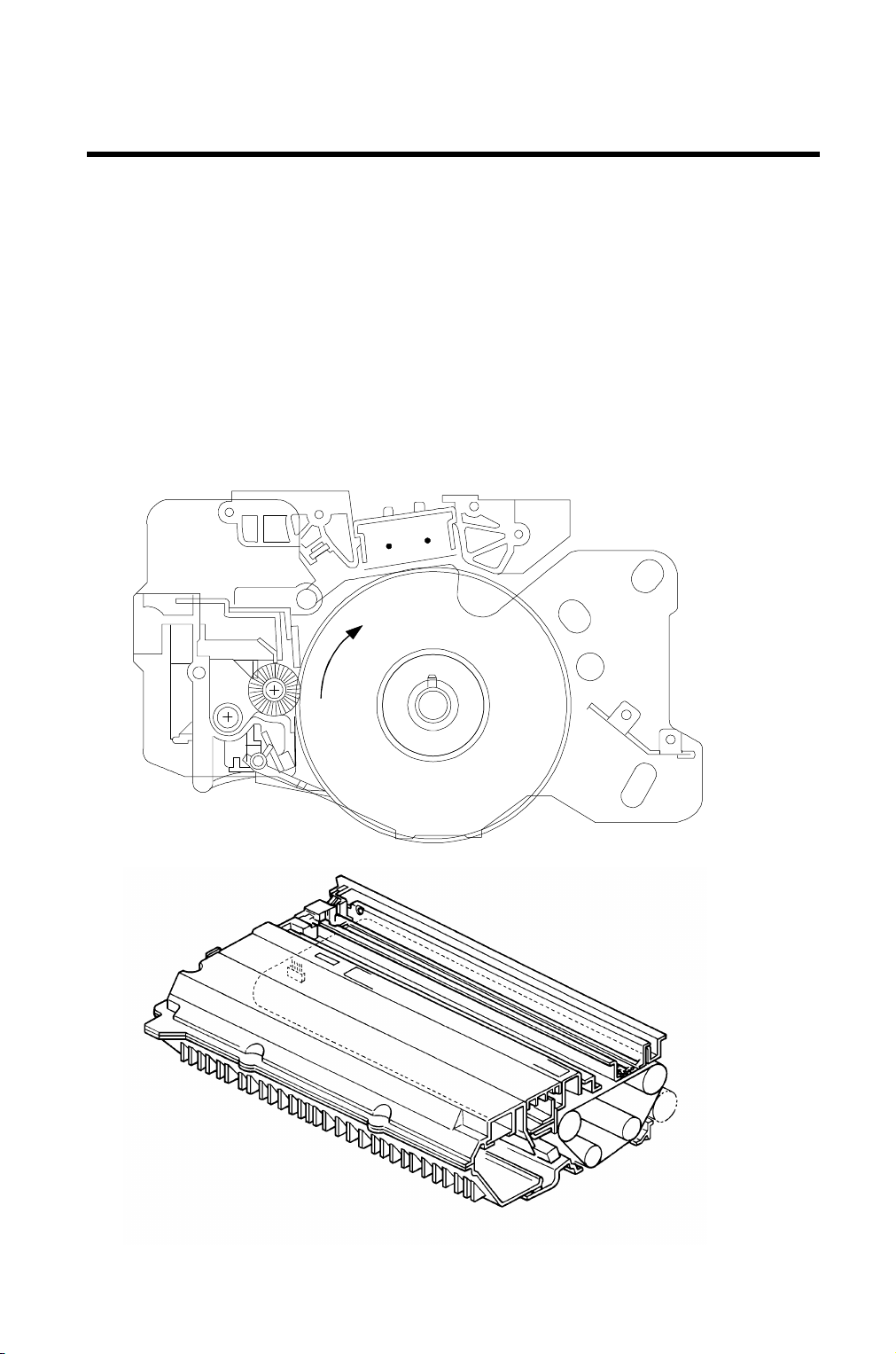
There are two types of OPCs used today: the drum type [A] and the belt type
[B].
The drum type has a base of aluminum or nickel. It is usually used in copiers,
as well as laser facsimile machines and laser printers.
The belt type has either a film of polyester or a nickel belt. The nickel belt has
a bond seam, while the polyester film is seamless. The belt type is used in laser facsimile machines and laser printers. It is not normally used in copiers.
[A]
[B]
OPC506.wmf
OPC505.img
3-1
Page 6

October 1st, 1995 COPY CYCLE
Overview
4. COPY CYCLE
4.1. Overview
The OPC transfers an image of the original to the output paper (copy or fax).
It does this during the copy cycle.
Charge
Corona
Wire
1
-750V
2
Voltage
-100V
Light
- ------CTL
+ +
CGL
- -
+ ++++ +++
CTL
CGL
Quenching
Light
- ----
+ + +++
+ + +++
Charge
Corona Unit
- ------CTL
CGL
+ ++++ +++
Base
6
---- -+-
Cleaning
Assembly
Base
+
+
- ---CTL
CGL
+ + +++
+
+
5
Transfer
Corona Unit
Paper
- -
++ ++
- ---CTL
CGL
+ + +++
Transfer
Corona
Wire
Development
Roller
+
+
- ---CTL
CGL
+ + +++
4
+
+
+
+
P/P N/P
3
Development
Roller
-
-
- ----
-
-
CTL
CGL
+ + +++
Base
-
-
-
-
4-1
Page 7

COPY CYCLE October 1st, 1995
The Steps of the Copy Cycle
4.2. The Steps of the Copy Cycle
The following is a step-by-step description of how the OPC functions during
the copy cycle.
1. Charge
The transfer corona wire applies a negative charge to the surface of the
CTL (about -750 V). Due to a capacitor-like effect, a positive charge is produced on the base.
2. Exposure
Light (either reflected fluorescent light or laser light) strikes the OPC. This
light causes the CGL to generate positive and negative charges. The positive charges are attracted to the CTL’s surface negative charge. The negative charges are attracted to the CGL’s surface positive charge.
As a result, where light has struck the CTL, the CTL’s surface voltage drops
to about -100V.
Note: When exposure is done with a fluorescent lamp, the reflected light
corresponds to the white areas of the original. When exposure is
done with a laser diode, the light corresponds to the black areas of the
original, in most machines.
Exposure, therefore, creates a charged latent image of the original on
the surface of the OPC.
3. Development
The development roller applies charged toner to the OPC that will adhere
to the latent image.
In Positive/Positive (P/P) development, the development roller applies positively charged toner to the OPC. The toner is attracted to the negative areas where light has not contacted the OPC.
In Negative/Positive (N/P) development, the development roller applies negatively charged toner to the OPC. The toner is attracted to the relatively positive
areas where light has contacted the OPC.
P/P development is used when the light reaching the OPC corresponds to
white areas of the original. P/P development is used when exposure is done
with a fluorescent lamp, and in some earlier laser engines that used the "writeto-white" system.
N/P development is used when the light reaching the OPC corresponds to
black areas of the original, as in most laser-based print engines.
4-2
Page 8

October 1st, 1995 COPY CYCLE
The Steps of the Copy Cycle
4. Transfer
The transfer corona wire develops a charge of opposite polarity to the
toner (negative in P/P development, positive in N/P development). The
wire applies this charge to the back of the output paper. This charge,
therefore, will attract the toner (attached to the OPC in the latent image
of the original) to the paper. The paper then goes on to the fusing unit
where the toner is fused to the paper.
5. Cleaning
The cleaning assembly removes any residual toner on the OPC after
transfer.
6. Quenching
When the quenching light is applied to the OPC, it causes the CGL to
generate positive and negative charges (as in the exposure step).
These charges similarly cause the voltage on the surface of the CTL to
drop to about -100 V, except that in quenching, the entire surface of
the OPC is exposed. Therefore, the quenching lamp removes the high
negative potential remaining from the previous stages of the copy cycle. This readies the OPC for the next copy cycle.
4-3
Page 9

October 1st, 1995 OPC CHARACTERISTICS
General Characteristics
5. OPC CHARACTERISTICS
5.1. General Characteristics
These characteristics include:
1. The ability to accept a high negative electrical charge in the dark. (The
electrical resistance of a photoconductor is high in the absence of light.)
2. The ability to dissipate the electrical charge when exposed to light.
(Exposure to light greatly increases the conductivity of a photoconductor.)
3. The ability to dissipate an amount of charge in direct proportion to the
intensity of the light applied. Therefore, the greater the intensity of light
applied to the photoconductor, the smaller the voltage remaining on the
OPC.
4. An OPC is less sensitive to changes in temperature than selenium-
based drums (also known as F type drums).
5. An OPC is less sensitive to changes in rest time (in other words, it is
not so sensitive to light fatigue as F type drums). It is therefore
unnecessary to compensate development bias voltage for variations in
rest time.
6. Lower cost than an F type drum.
7. No need for special disposal considerations.
5-1
Page 10

OPC CHARACTERISTICS October 1st, 1995
Special Characteristics
5.2. Special Characteristics
5.2.1. Deterioration in OPC Thickness
Some abrasive actions in the copy cycle gradually reduce the thickness of the
CTL over time. These actions include cleaning, development (application of
the ferrite carrier by the development roller), and separation (the pick-off pawl
separating the page from the OPC).
This reduced thickness results in a decrease in the capacitor effect on the
OPC (resulting in reduced chargability). This will affect the chargeability of
analog OPCs and digital OPCs at different rates. (See the chart below.)
The chargeability of the analog OPC decreases much more rapidly than that
of the digital OPC. For the same amount of reduction in CTL thickness, therefore, the copy quality of the analog OPC decreases much more rapidly than
for digital OPCs.
3000
Analog OPC at
560nm
Chargeability
(V cm2/µJ)
2000
1000
302515 2010
CTL Thickness (µm)
OPC
Digital
OPC
OPC502.wmf
Analog OPCs use positive/positive development. Since positively charged
toner is applied to the OPC, the amount of negative voltage the OPC can accept is very important to copy quality.
Digital OPCs use negative/positive development. Since negatively charged
toner is applied to the OPC, a decrease in the OPCs negative voltage will not
have such a drastic effect on copy quality. (It will, however, cause a "dirty"
background appearance.)
Note: In the past, positive/positive development has sometimes been used
with digital OPCs. In this case, the laser exposure corresponds to
the white areas of the original. However, in most printouts, there are
many more white areas than black areas, so positive/positive development leads to a reduced OPC lifetime.
5-2
Page 11

October 1st, 1995 OPC CHARACTERISTICS
Special Characteristics
5.2.2. Wavelength of Light
The wavelength of fluorescent light is 450 nm ~ 650 nm. The wavelength of laser light is 780 nm. The charge generation material (CGM) for analog and
digital OPCs is designed differently due to these different wavelengths. The
difference is most easily observed in the colour of pigmentation
The CGM in an analog OPC is designed for maximum power output (chargeability) at 450 nm ~ 650 nm (depending on the machine). This will allow the
OPC to work optimally with reflected fluorescent light.
The CGM in a digital OPC is designed for maximum power output (chargeability) at 780 nm. This will allow the OPC to work optimally with laser light.
650nm
3000
2000
780nm
2000
Chargeability
(V cm2/µJ)
1000
500
600 800700
Wavelength of Light ( nm)
OPC503.wmf
Analog OPCs
Chargeability in relation to the
wavelength of light applied.
Chargeability
(V cm2/µJ)
1000
500
600 800700
Wavelength of Light (nm)
Digital OPCs
Chargeability in relation to the
wavelength of light applied.
OPC504.wmf
5-3
Page 12

OPC CHARACTERISTICS October 1st, 1995
Differences between Analog and Digital OPCs
5.3. Differences between Analog and Digital OPCs
Item Analog OPCs Digital OPCs
CGL Contains a material that
responds to the wavelength of
white light, such as light from a
fluorescent lamp.
CTL The CTLs are also different, to match the CGL that is used.
CTL Thickness vs
Chargeability
Development
Method
Image Transfer The image transfer charge has
If the CTL thickness is reduced,
the chargeability is also reduced.
Positive/positive only. Negative/positive or
the same polarity as the charge
corona unit.
Contains a material that
responds to the appropriate
laser wavelength.
The same as for Analog OPCs.
The chargeability does not,
however, decrease as rapidly as
in analog OPCs.
positive/positive can be used.
Negative/positive is mainly used.
The image transfer charge has
the opposite polarity as the
charge corona unit.
5-4
Page 13

October 1st, 1995 EFFECTS OF ENVIRONMENTAL FACTORS
Light
6. EFFECTS OF ENVIRONMENTAL FACTORS
6.1. Light
The CGL generates positive and negative charges when the OPC is exposed to
light. These charges flow normally (see page 4-1) when the OPC is in the machine. However, exposing the OPC to light after it has been removed from the
machine also causes the CGL to generate charges. Since there is no path for current flow, these charges may remain in the CGL. When the OPC is put back in
the machine, these stray charges will result in decreased chargeability and reduced copy quality.
OPC exposure to normal fluorescent lighting for 5~20 minutes will generate
stray charges. It is important, therefore, to cover the OPC with paper when removing it from the machine. If the OPC has been inadvertently exposed to
light, it is very important to shield it from any additional light for 10~15 minutes before making a copy. This will allow the charges to dissipate naturally. If
a copy is made before doing this, the stray charges will remain in the OPC. It
will take 1~2 months for the OPC to return to a normal condition. During this
time the residual voltage will be high and copy quality will be reduced.
6.2. Temperature
The melting temperature of the CTL is 60 °C ~ 70 °C. Take care (especially
during warehouse storage) not to exceed this temperature. Packing materials
may stick to the melting CTL. This will destroy the OPC.
6-1
Page 14

EFFECTS OF ENVIRONMENTAL FACTORS October 1st, 1995
Gases
6.3. Gases
Certain gases will affect the OPC.
Ozone
Ozone (O3) is produced in most machines by the charge corona unit and the
transfer corona unit. Usually, a machine which uses these units is equipped
with an ozone fan and ozone filter. This equipment removes the ozone from
the machine.
O3 will reduce the chargability of the OPC. O3 can affect both analog and digital OPCs.
Ammonia and Nitrogen Oxides
Ammonia (NH3) and nitrogen oxides (NOx) may reach the OPC from the outside environment.
NH3 can affect analog OPCs by removing negative charges from the CTL (as
the analog CTL material easily releases negative charges). This will reduce
chargeability and copy quality.
NOx can affect digital OPCs by adding negative charges to the CTL (as the
digital CTL material easily accepts negative charges). This will reduce chargeability and copy quality.
6.4. Dust and Oil
Dust and oil should be removed from the OPC. Dust and oil prevent toner from adhering to the OPC. This reduces copy quality.
Remove oil with a dry or slightly dampened cloth. Be sure to wipe the OPC
dry after applying a dampened cloth (use a clean dry cloth). It is important
that no water remains on the OPC.
Remove dust with a dry cloth.
Note: Never apply alcohol to the OPC.
6-2
 Loading...