

Page 1

Container Stacker
Unpacking & Setup
Instructions
© 2007 Ricoh Corporation
5 Dedrick Place
West Caldwell, NJ 07006
January 2007
337641-006B
Page 2

© 2007 Ricoh Corporation. All rights reserved.
No part of this document may be reproduced without the expressed permission of Ricoh
Corporation.
The material in this document is for informational purposes and is subject to change
without notice. Ricoh Corporation assumes no responsibility for errors or omissions in
this document. No liability is assumed for any damages resulting from the use of the
information it contains.
TRADEMARK
Adobe and Postscript are registered trademarks of Adobe Systems Incorporated. PCL
is the trademark of Hewlett Packard. Ethernet is a trademark of Xerox Corporation.
Windows XP is a trademark of Microsoft Corporation. Digital Document Publisher and
DDP and its associated logo mark are the trademarks of Ricoh Corporation. Ricoh and
the Ricoh trademark are registered trademarks of Ricoh, Ltd. All rights reserved.
All other terms and product names may be trademarks or reg istered trade marks of the ir
respective owners and are hereby acknowledged.
NOTICE TO USER
In an effort to meet the demands of a rapidly changing technology, the manufacturer is
continually developing new features and functions to meet changing printing or printer
needs. Please be sure to consult all manual updates or addenda when using this
product’s documentation.
This document contains TrueType fonts from Monotype Imaging Inc. Reproduction of
these fonts is prohibited.
The software embedded in this product is based in part on the work of Independent
JPEG Group.
The software embedded in this product uses software by CMU. Copyright 1988, 1989
by Carnegie Mellon University. All rights reserved.
Permission to use, copy, modify, distribute and sell this software and its documentation
for any purpose and without fee is hereby granted, provided that the avove copyright
notice appears in all copies and that both the copyright notice and permission notice
appear in supporting documentation, and the name of CMU not be used in advertising
or publicity pertaining to distribution of the software without specific written prior
permission.
The software embedded in this product uses the software by Sam Leffler and Silicon
Graphics.
Copyright (c) 1988-1997 Sam Leffler
Copyright (c) 1991-1997 Silicon Graphics, Inc
Permission to use, copy, modify, distribute and sell this software and its documentation
for any purpose and without fee is hereby granted, provided that the above copyright
notice appear in all copies of the software and related documentation, and (ii) the names
of Sam Leffler and Silicon Graphics may not be used in advertising or publicity pertaining
to distribution of the software without specific, written prior permission of Sam Leffler and
Silicon Graphics.
Page 3

i
Revisions
Revision Page No. (Contents) Date
A Original Release - ECO-1554 October 2004
B Generic Version; Add rev history page, copyright page updated January 2007
Page 4

Table of Contents i
Table of Contents
Chapter 1. Container Stacker Installation Instructions
Installation Area . . . . . . . . . . . . . . . . . . . . . . . . . . . . . . . . . . . . . . . . . . . . . . . . . . . . . . . . . . . . 1-1
Environmental Conditions . . . . . . . . . . . . . . . . . . . . . . . . . . . . . . . . . . . . . . . . . . . . . . . . . . . . 1-1
Location of Leveling Bolts and Casters . . . . . . . . . . . . . . . . . . . . . . . . . . . . . . . . . . . . . . . . . . 1-1
Tools Required . . . . . . . . . . . . . . . . . . . . . . . . . . . . . . . . . . . . . . . . . . . . . . . . . . . . . . . . . . . . . 1-2
Important Safety Instructions . . . . . . . . . . . . . . . . . . . . . . . . . . . . . . . . . . . . . . . . . . . . . . . . . . 1-2
Unpacking of Container Stacker 1 or 2. . . . . . . . . . . . . . . . . . . . . . . . . . . . . . . . . . . . . . . . . . . 1-3
Components in the Package . . . . . . . . . . . . . . . . . . . . . . . . . . . . . . . . . . . . . . . . . . . . . . . . 1-3
Unpacking . . . . . . . . . . . . . . . . . . . . . . . . . . . . . . . . . . . . . . . . . . . . . . . . . . . . . . . . . . . . . 1-4
Preparation for Installation of Container Stacker 1 or 2 . . . . . . . . . . . . . . . . . . . . . . . . . . 1-8
Installation Configuration . . . . . . . . . . . . . . . . . . . . . . . . . . . . . . . . . . . . . . . . . . . . . . . . . . . . 1-10
Prepare the Printer. . . . . . . . . . . . . . . . . . . . . . . . . . . . . . . . . . . . . . . . . . . . . . . . . . . . . . . . . . 1-10
Install Container Stacker 1 or 2 . . . . . . . . . . . . . . . . . . . . . . . . . . . . . . . . . . . . . . . . . . . . 1-12
Installation of Container Stacker 2 and Container
Stacker 1 . . . . . . . . . . . . . . . . . . . . . . . . . . . . . . . . . . . . . . . . . . . . . . . . . . . . . . . . . . . . . . . . . 1-21
Installation of Container Stacker 2 and Standard Finisher . . . . . . . . . . . . . . . . . . . . . . . . . . . 1-26
Standard Finisher (70 ppm) . . . . . . . . . . . . . . . . . . . . . . . . . . . . . . . . . . . . . . . . . . . . . . . 1-26
Standard Finisher (92/184 ppm) . . . . . . . . . . . . . . . . . . . . . . . . . . . . . . . . . . . . . . . . . . . 1-29
Adjustment . . . . . . . . . . . . . . . . . . . . . . . . . . . . . . . . . . . . . . . . . . . . . . . . . . . . . . . . . . . . . . . 1-33
Appendix A. Installation/Maintenance Area
70/92 ppm Printer and Container Stacker 1 . . . . . . . . . . . . . . . . . . . . . . . . . . . . . . . . . . . . . . .A-1
70/92 ppm Printer, High Capacity Hopper, Container Stacker 1 and Container Stacker 2 . . .A-2
70/92 ppm Printer, High Capacity Hopper, Container Stacker 2 and Standard Finisher . . . . .A-3
184 ppm Printer and Container Stacker 1 . . . . . . . . . . . . . . . . . . . . . . . . . . . . . . . . . . . . . . . . . A-4
184 ppm Printer, High Capacity Hopper, and Container Stacker 1 . . . . . . . . . . . . . . . . . . . . .A-5
184 ppm Printer, Container Stacker 1, and Container Stacker 2 . . . . . . . . . . . . . . . . . . . . . . .A-6
184 ppm Printer, HIgh Capacity Hopper, and Container Stacker 1 and 2 . . . . . . . . . . . . . . . .A-7
184 ppm Printer, Container Stacker 2, and Standard Finisher . . . . . . . . . . . . . . . . . . . . . . . . . A-8
184 ppm Printer, High Capacity Hopper, Container Stacker 2, and Standard Finisher . . . . . .A-9
Page 5

ii Table of Contents
Page 6
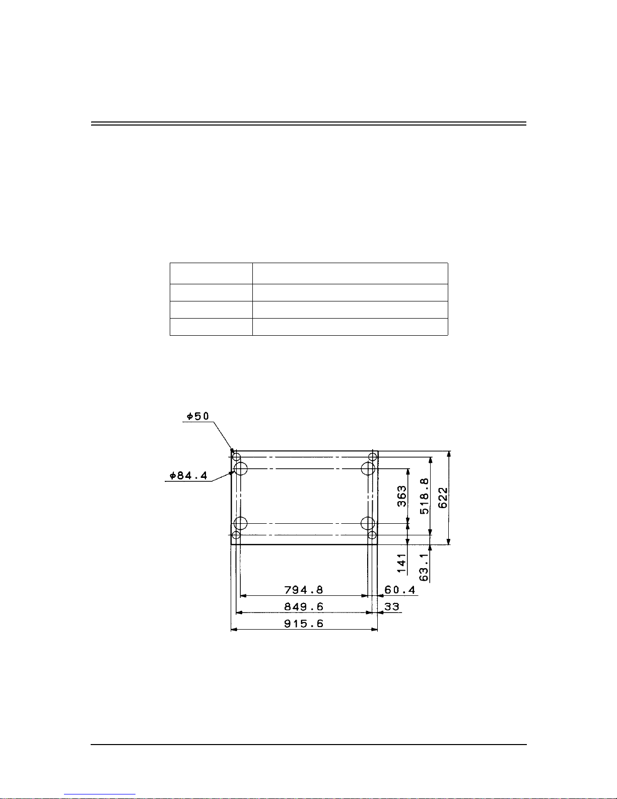
Container Stacker Installation Instructions 1-1
Chapter 1
Container Stacker Installation Instructions
Installation Area
Refer to Appendix 1.
Environmental Conditions
The location where the Container Stacker is installed must meet the following
environmental conditions:
Location of Leveling Bolts and Casters
Install the leveling bolts and the casters to the Container Stackers 1 and 2 as follows.
ITEM CONDITION
Temperature 10 to 32 °C
Humidity 20 to 80%RH (non-condensing)
Altitude 0 to 2,100 m
Page 7

1-2 Container Stacker Installation Instructions
Tools Required
The following tools are required:
Important Safety Instructions
Observe the following safety instructions for safe unpacking and installation.
1. Keep the work area clean and free of loose parts.
2. Wear suitable clothing. Pay attention to ties, sleeves, and shirts so that they are
not caught in the equipment.
3. Work in a stable position. Working in a strained position may cause injury.
4. If you must move the equipment, be sure the path is clear of obstacles and high
voltage areas or wires.
5. Unplug the equipment before cleaning. Unplug the Printer from the outlet before
cleaning the inside of the Printer and label the power cord plug to prevent other
persons from plugging it in while you are cleaning.
6. Be sure to use the proper tools that are in good condition. Use of worn or
improper tools can cause injury.
TOOL APPLICATION
Cutter For unpacking
Phillips Screwdriver
No. 2 shaft length: approx. 100 mm
For installing the Printer and Containter Stacker
Adjustable open end wrench (Span; 30mm) For adjustment of leveling bolts
IC Gripper For replacement of nv-RAM
Level For installation of the Printer and Container
Stacker
Page 8

Container Stacker Installation Instructions 1-3
Unpacking of Container Stacker 1 or 2
Components in the Package
CAUTION!
When using a crane or forklift, handle the equipment with care. Do not drop, bump
or turn sideways.
Perform the unpacking procedure in a clean, dry location.
Do not place heavy objects (5 kg or more) on top of the equipment.
Keep the equipment balanced when lifting with a forklift. Use cushion materials to
avoid damage.
Move the equipment at a speed of 300 mm/sec (1.08 km/h) or slower. Do not tilt the
equipment more than 15
°. Slope on the path can be no more than 15°.
Do not allow condensation to form on the equipment.
Component Quantity
Container Stacker 1 or
Container Stacker 2
1
Accessory box 1
Page 9
1-4 Container Stacker Installation Instructions
Unpacking
1. Using a cutter, remove the V bandS from the shipping box and remove the cap.
V band
Corner packing
Plastic bag
Tape
V band
P.P band
Page 10
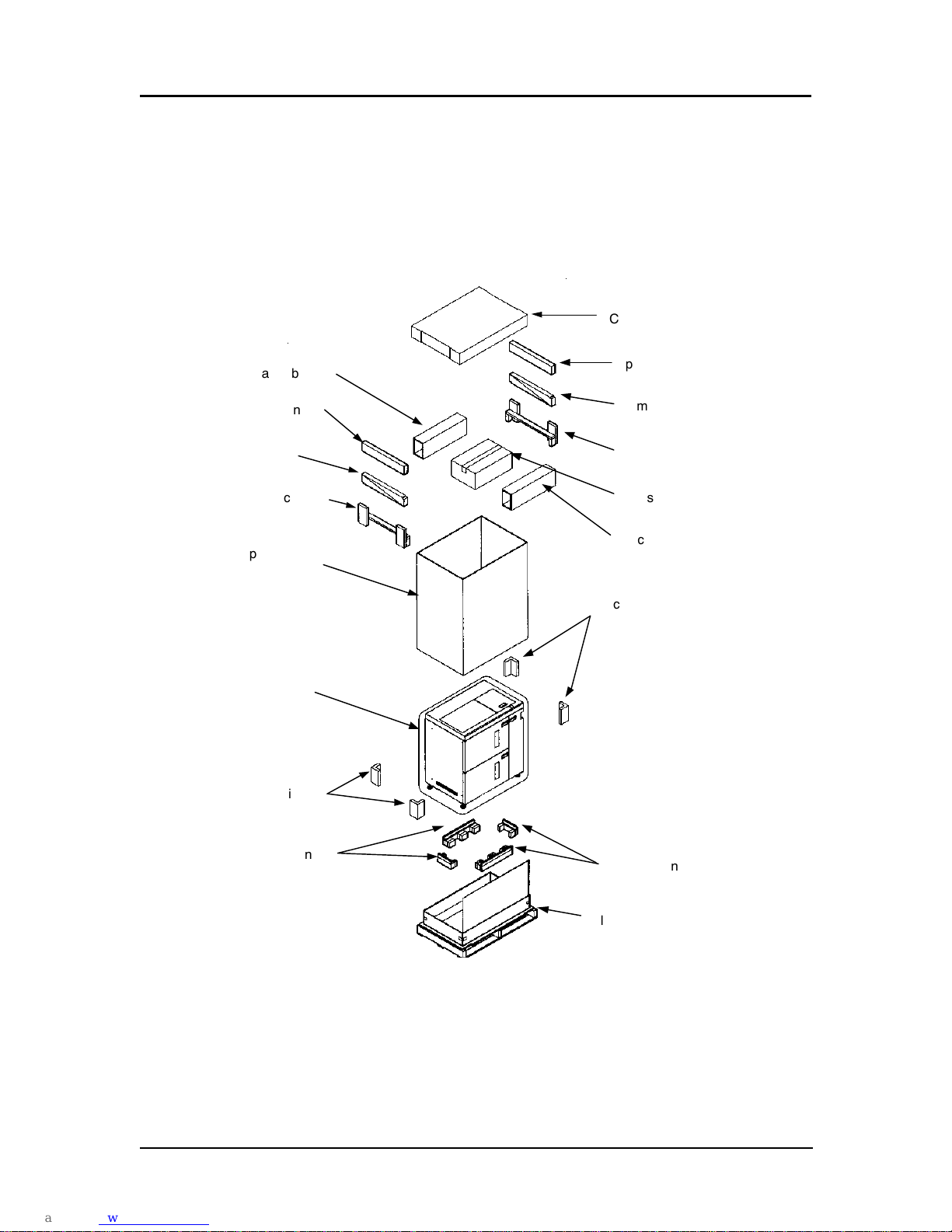
Container Stacker Installation Instructions 1-5
2. Remove the accessory box, spacer box, spacer packing, ramps and upper packing.
3. Remove the shipping box, band, and four corner pieces.
4. Peel off the adhesive tape and remove the plastic bag.
5. Cut the tape from the 4 corners of the base packing and push down the side of the
pallet to become an incline board.
Cap
Spacer packing
Pallet
Shipping box
Accessory box
Upper packing
Ramp
Spacer box
Upper packing
Corner packing
Base packing
Corner packing
Spacer packing
Plastic bag
Ramp
Base packing
Spacer box
Page 11
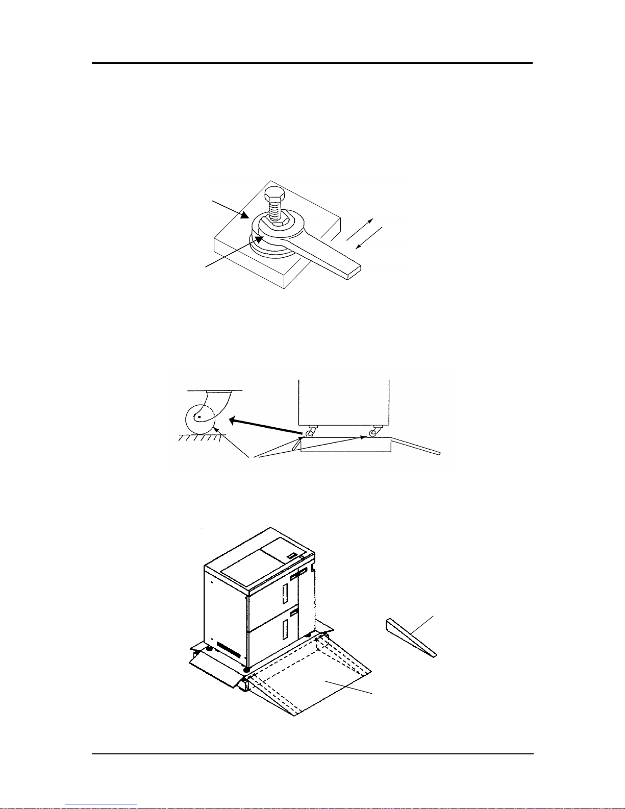
1-6 Container Stacker Installation Instructions
6. Romove the tape from the leveling bolts, take out the four wooden spacers from
the accessory box, and place them at the bottom of the bolts (under the plastic
bag).
7. Using an open-end wrench, raise the container stacker by rotating the leveling
bolts.
8. Remove the 4 pieces of base packing.
9. Turn all the casters in the same direction.
10. Install the ramps (two on each side) under the incline board.
Wood spacer
Leveling bolt
Down
Up
Ramp
Incline Board
Page 12

Container Stacker Installation Instructions 1-7
11. Raise the leveling bolts and remove the wood spacers.
12. Carefully slide the container stacker onto the floor.
WARNING!
Do not attempt the following step without another person to help guide the
stacker down the ramp.
Page 13
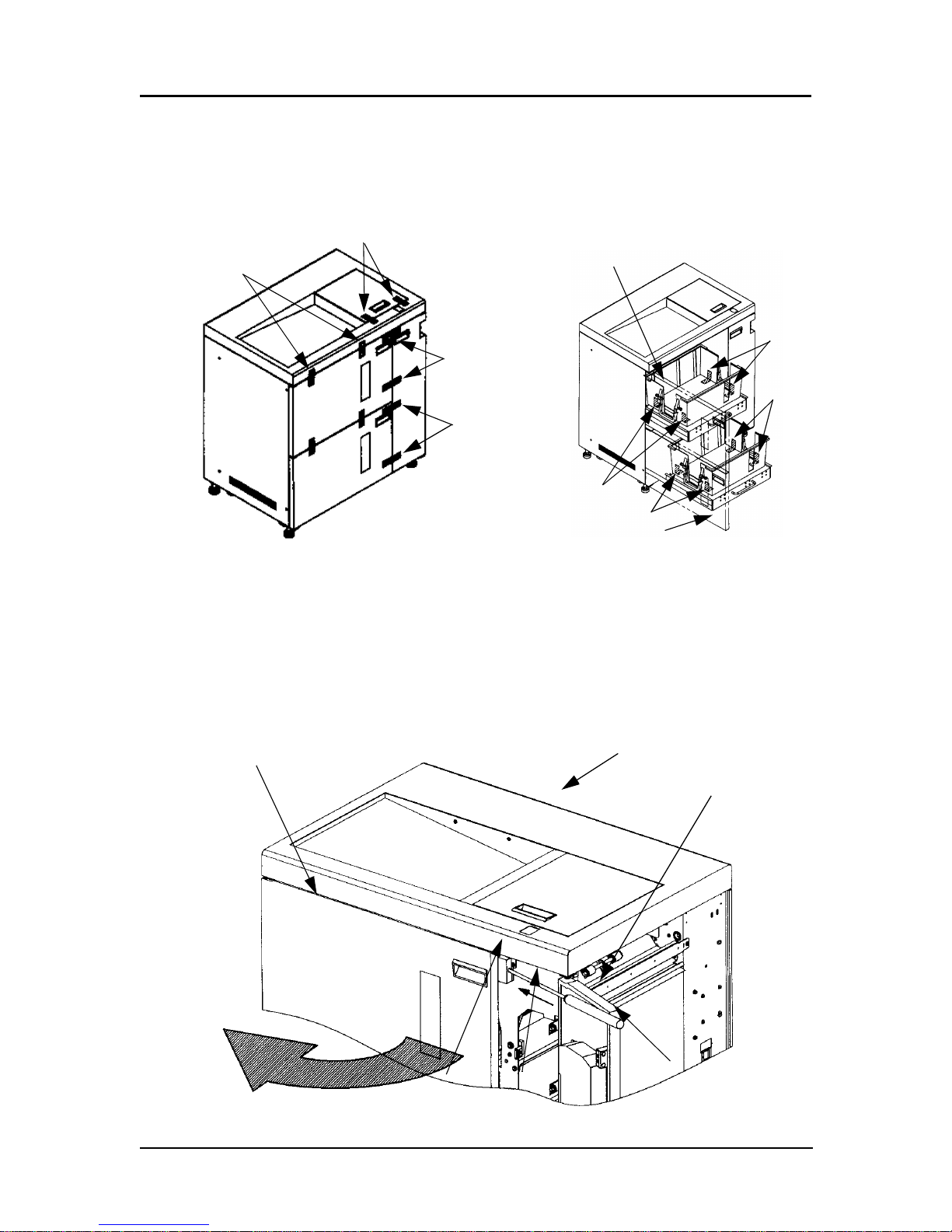
1-8 Container Stacker Installation Instructions
Preparation for Installation of Container Stacker 1 or 2
1. Peel off adhesive tape from the Container Stacker 1 or 2.
2. Open Front Cover L and peel off the adhesive tape
Opening procedure for Front Cover L
1. Open Front Cover R.
2. Using a Phillips screwdriver, push cover release A in the direction of the arrow
and open Front Cover L.
Ta pe
Tape
Ta pe
Ta pe
Ta pe
Tape
Tape
Tape
Front Cover L
Front Cover L
Front Cover L
Container Stacker 1 or 2
Phillips Screwdriver
Front Cover R
Arrow
A
Page 14
Container Stacker Installation Instructions 1-9
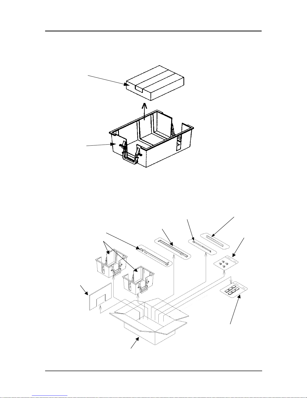
3. Take the box containing the CP417 assembly out of the lower basket. |
(70 ppm only)
4. Take the components out of the accessory box.
CP417 Assy
Basket
Screw
Joint bracket (L)
Basket (small)
Joint bracket (U)
Guide Plate(L)
Guide Plate(U)
Partition
Hopper spacer ass’y
Details of screw
(1) M3 x 8 2 pieces
(2) M4 x 8 4 pieces
(3) M4 x 12 6 pieces
A
ccessory box
Page 15
1-10 Container Stacker Installation Instructions
Installation Configuration
The table below shows the configuration of Printer and Post devices. Installation of
each configuration should be done according to the reference page shown the in table
below.
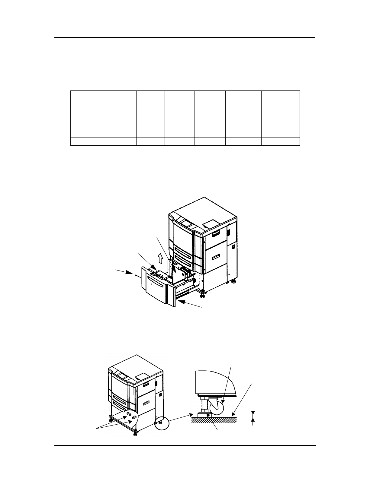
Prepare the Printer
70/92 ppm
1. Remove the 2000 sheet hopper.
2. Turn the four leveling bolts until the casters do not touch the ground.
3. Place a level on the Printer frame and adjust the leveling bolts until horizontal
level is achieved.
Configuration Printer
Container
Stacker 1
Container
Stacker 2
Standard
Finisher
DDP70e
Standard
Finisher
DDP92/184
Reference
Page
1xx 8
2 x x x 8, 16
3 x x x 8, 21
4 x x x 8, 24
Paper Guide
Lever
M4 Screw
2000 Sheet Hopper
Gap
Caster
Leveling Bolt
Floor
Level
(Max 1mm)
Page 16

Container Stacker Installation Instructions 1-11
4. Reinstall the 2000 Sheet Hopper.
184 ppm
1. Open the Front Cover of the printer and loosen the two M4 screws. (184 ppm
only)
2. Pull the upper part of the Front Lower Cover forward and unhook it by lifting and
pulling forward.
M4 Screw
2000 Sheet Hopper
Rear Engine
Hook
Front Cover
M4 Screw
Front Lower Cover
Page 17

1-12 Container Stacker Installation Instructions
3. Turn the four leveling bolts until the casters no longer touch the floor.
4. Using a Level, adust the horizontal level of the rear engine.
Install Container Stacker 1 or 2
1. Remove the two M3x8 screws and Static Electricity eliminator from the Printer.
2. Install the Guide Plate (U) with the Static Electricity eliminator using the two
M3x8 screws.(the front is lettered on the surface).
3. Install the Guide Plate (L) using the two M3x8 screws with washers.
4. Install Joint Bracket (U) and Joint Bracket (L) using the two M4x8 screws.
NOTE:
These installation instructions apply to the 70, 92 and 184 ppm
printers.When installing a Container Stacker on a 184 ppm printer, the
word printer always refers to the Rear Engine unless otherwise specified.
NOTE:
Take care that nothing interferes with the static eliminator.
(Max 1mm)
Gap
Leveling Bolt
Caster
Floor
Rear Engine
Level
Page 18

Container Stacker Installation Instructions 1-13
5. Install Joint Bracket (U) and Joint Bracket (L) using the two M4x8 screws.
6. Remove the six M4 screws. Unhook the lower hook of the Rear Cover and
remove the Rear Cover by lifting and pulling it forward.
M4x8 Screw
M4x8 Screw
Joint Bracket (L)
Joint Bracket (U)
M3x8 Screw with Washer
Guide Plate (U)
Guide Plate (L)
Static Electricity Eliminator
M3x8 Screw
Rear Cover
M4 Screws
Page 19

1-14 Container Stacker Installation Instructions
7. Remove the six M4 Screws and the Rear Cover.
8. Attach Container Stacker 1 or 2 to the Printer and loosely install the screws.
NOTE:
Refer to page 5 for instructions on opening Front Cover L.
Rear Cover
M4 Screws
Container Stacker 1 or 2
M4x12 Screws
Frame Projection Part
M4x12 Screws
Page 20

Container Stacker Installation Instructions 1-15
9. Close Front Cover R to allow you to see the gap between the Printer and
Container Stacker. Using the leveling bolts, adjust the height of the Container
Stacker until the Container Stacker frame projection is level with the Printer
Paper Guide projection. Adjust the horizontal level of the Container Stacker by
placing a level on the stacker frame in the three locations shown below. Tighten
the screws completely.
10. Verify the gap at A, B, C, and D is nearly equal.
Stacker Frame
Printer Paper Guide
Level
Front Cover L
Projection
Projection
Same Height
Leveling Bolts
Connection Part Details
A
B
C
D
Adjust the parallel gap
Page 21

1-16 Container Stacker Installation Instructions
11. Open the L Paper Guide A of the Container Stacker and make sure that the SB
Cover can be opened. If the cover cannot be opened, repeat steps 8 and 9 to
readjust the Container Stacker.
L Paper Guide A
SB Cover
Page 22

Container Stacker Installation Instructions 1-17
12. Remove the OC P/K ass’y from the Printer. Remove the CP411 P/K and CP P/K
holder (70 ppm only).
13. Remove the OC P/K ass’y and CP P/K holder from the Printer (92/184 ppm only).
14. Remove the nv-RAM from the CP411 P/K using an IC gripper. Install the
removed nv-RAM into the CP417 P/K (70 ppm only)
15. Connect the CST AC cable coming from the Container Stacker to J236 on the
power supply of the Printer (Connection 1 on the figure below). At this time,
connect the CE AC cable that was disconnected from J236 to the connector of the
CST AC cable (Connection 2 on the figure below).
16. Mount the CST FG cable coming from Container Stacker side on the Printer
frame using an M4 screw (Connection 3 on the following illustration).
17. Install the CP417 P/K on the CP P/K holder, and then install it and the board in
the Printer. (70 ppm only)
18. Install the CP P/K holder and OC P/K ass’y in the Printer (92/184 ppm only)
19. Connect the FNS IF cable of the 20 pin black connector coming from the Printer
to the J680 connector of ST09X board in Container Stacker (Connection 4 on the
figure below). Do not use the 4 pin white connector (Disconnection 2 on the
following illustration).
CPXXX P/K
CP P/K holder
OC P/K ass’y
nv-RAM
M4 Screw
M4 Screw
CST AC Cable
CST FG Cable
M4 Screw
Dent side
Page 23

1-18 Container Stacker Installation Instructions
20. Disconnect the 4 pin white connector of the DC IF cable of the Printer from the
FNS IF cable (Disconnection 1 on the figure below), then connect it to the RB
cable of the 4 pin white connector coming from Container Stacker (Connection 5
on the following illustration) (70/92 ppm only).
21. Connect the CS relay cable of accessory box of the printer to the 4 pin white
connector of the FNS IF cable and the RB cable of the 4 pin white translucent
connector of the Container Stacker (Connection 5 on the following illustration.)
(184ppm only)
NOTE:
Put the cable through opening “A” of the Printer.
On SW1 mounted on the CPXXX P/K, set switch No. 5 to ON and set switch No. 2
and No. 8 to OFF. (Front Engine of 184 ppm printer)
CE AC Cable
Connector : 2 pin white
Connector : 2 pin
PS
Connection 1 and 2 Details
70/92 ppm
CTS AC Cable
M4 Screw
(Connection 3)
Opening A
RB Cable
Connection 5
(4 pin white)
Disconnection 3
(2 pin white)
Connection 4
(20 pin black)
CST FG Cable
CE AC Cable
Connection 2
Connection 1
FNS IF Cable
Disconnection 2
(4 pin white)
Disconnection 1
(4 pin white)
DC IF Cable
Page 24

Container Stacker Installation Instructions 1-19
CTS AC Cable
M4 Screw
(Connection 3)
Opening A RB Cable
Connection 5
(4 pin white
CS Relay Cable
Connection 5
(4 pin white)
Disconnection 3
(2 pin white)
Connection 4
(20 pin black)
FNS IF Cable
(coming from Front Engine)
CST FG Cable
CE AC Cable
Connection 2
Connection 1
translucent)
184 ppm
CE AC Cable
Connector : 2 pin white
Connector : 2 pin
PS
Connection 1 and 2 Details
Page 25

1-20 Container Stacker Installation Instructions
22. Install the Rear Cover of the Printer and the Rear Cover of the Container Stacker.
M4 Screw
Page 26

Container Stacker Installation Instructions 1-21
Installation of Container Stacker 2 and Container
Stacker 1
1. Remove the two M3x8 Screws and Static Electricity eliminator from the Printer.
2. Attach the Guide Plate (U) with the Static Electricity eliminator using the two
M3x8 Screws.
3. Install Joint Bracket (U) and Joint Bracket (L) using the two M4x8 Screws.
NOTE:
Refer to page 9 for installation of the Printer and the Container Stacker 2.
M4x8 Screw
Guide Plate
Container Stacker 2
Static Electricity Eliminator
Joint Bracket U
M3 Screw
Joint Bracket L
Page 27

1-22 Container Stacker Installation Instructions
4. Remove the six M4 Screws and remove the Rear Cover from Container Stacker 1.
5. Attach Container Stacker 1 to Container Stacker 2 and loosely install the screws
M4 Screws
Rear Cover
Container Stacker 1
Container Stacker 1
M4x12 Screws
Frame Projection Part
Container Stacker 2
M4x12 Screws
M4x12 Screws
Page 28

Container Stacker Installation Instructions 1-23
6. Close Front Cover R to allow you to see the gap between the Printer and
Container Stacker. Using the leveling bolts, adjust the height of the Container
Stacker until the Container Stacker frame projection is level with the Paper Guide
projection. Adjust the horizontal level of the Container Stacker by placing a level
on the stacker frame in the three locations shown. Tighten the screws completely.
7. Verify the gap at A, B, C, and D are nearly equal.
NOTE:
Refer to page 5 for instructions on opening Front Cover L.
Stacker Frame
Stacker Paper Guide
Level
Front Cover L
Projection
Projection
Same Height
Leveling Bolts
Connection Part Details
A
BCD
Adjust the gap in parallel
Page 29

1-24 Container Stacker Installation Instructions
8. Connect the AF cable of 4 pin white connector coming from the Container
Stacker 2 to the J680 on the ST09X P/K of the Container Stacker 1. (Connection 1
on the following illustration)
9. Take out the CST AC cable of 2 pin white connector from the Container Stacker 1
and connect it to the CST AC cable of 2 pin white connector of the Container
Stacker 2. (Connection 2 on the following illustration)
10. Take out the RB cable from the Container Stacker 1 and connect it to the RB
cable of Container Stacker 2. (Connection 3 on the following illustration)
11. Mount the CST FG cable coming from Container Stacker 1 on the frame of
Container Stacker 2 using M4 Screw (Connection 4 on the following illustration).
NOTE:
Put the cable through opening “A” of the Printer.
On SW1 mounted on the CPXXX P/K, set switch No. 4 and No. 5 to ON
and set No. 2 and No. 8 to OFF. (Front Engine of 184 ppm)
Connection 2
(2 pin white)
Connection 1
(20 pin black)
AF cable
RB cable
(For Container Stacker 2)
RB cable
(For Container Stacker 1)
Connection 3
(4 pin white)
CST AC cable
CST FG cable
M4 screw
Printer
Container Stacker 2
(W/ Sample tray)
(W/ Through path)
Opening “A”
Container Stacker 1
Disconnection 1
(4 pin white)
Disconnection 2
(2 pin white)
70/92 ppm
184 ppm: Connect the CS Relay Cable (see Page 19 Step 21.
Page 30

Container Stacker Installation Instructions 1-25
12. Install the Rear Covers of the Printer, Container Stacker 1 and Container
Stacker 2.
Printer Rear Cover
M4 Screws
Container Stacker 2 Rear Cover
M4 Screws
Container Stacker 1 Rear Cover
Page 31

1-26 Container Stacker Installation Instructions
Installation of Container Stacker 2 and Standard Finisher
Refer to “Standard Finisher Installation Instruction” for unpacking and preparation for
installation of the Standard Finisher.
Standard Finisher (70 ppm)
1. Remove the two M3 Screws and the Discharging Brush from Container Stacker 2.
2. Install the Guide Plate (G) together with the Discharging Brush and secure them
with two M3 Screws.
3. Install the Guide Plate (H), Connecting Stay and Main MT Plate.
4. Remove the Rear Covers from the Printer, Container Stacker 2 and standard
Finisher.
NOTE:
Refer to the “Standard Finisher Installation Instruction” regarding
unpacking and installation of the Finisher.
Connecting Stay
Container Stacker 2
M4 Screws
M3 Screws
M3 Screws
M4 Screws
Main MT Plate
Guide Plate (G)
Static Electricity Eliminator
Guide Plate (H)
w/Washer
Page 32

Container Stacker Installation Instructions 1-27
5. Attach the Standard Finisher to the Container Stacker 2.
6. Adjust the difference between the Stacker Paper Guide and the Printer Paper
Guide to 0 - 3 mm.
7. Verify the gap of A, B, C, and D are nearly equal. If not, adjust the leveling bolts.
Standard Finisher
M4 Screws
M4 Screws
Container Stacker
Finisher Paper Guide
Container Stacker 2 Paper Guide
Adjust the Parallel Gap
Adjustment Bolt
Loosen
0 to 3 mm
A
B
C
D
Page 33

1-28 Container Stacker Installation Instructions
8. Connect the AF cable of 4 pin white and 20 pin black connectors and coming
from the Container Stacker 2 to the connectors CN9 and CN10 of the Finisher.
(Connection 1 and 2 on the illustration below)
9. Install the Rear Covers of the Printer, Container Stacker 2 and Standard Finisher.
Install the connecting cover between the Container Stacker and the Standard
Finisher.
NOTE:
Put the cable through opening “A” of Container Stacker 2.
On SW1 mounted on the CPXXX P/K of the Printer, set switch No. 5 and
No. 8 to ON and set switch No. 2 to OFF.
70/92 ppm
184 ppm: Connect the CS Relay Cable
(see Page 19 Step 21).
Opening A
AF Cable Connection 2
(20 pin black)
Disconnection 1
(4 pin white)
Disconnection 2
(2 pin white)
Connection 1
(4 pin white)
Printer
Container Stacker 2
(with Throughpath)
Standard
Finisher
Page 34

Container Stacker Installation Instructions 1-29
Standard Finisher (92/184 ppm)
1. Install the Joint Cover/U, Joint Cover/F, the Joint Cover/R, and the Main Fixed
Plate/1.
2. Remove the Rear Covers from Printer, Container Stacker 2 and Finisher
NOTE:
Refer to the “Standard Finisher Installation Instruction regarding
unpacking and installation of the Finisher.
Container Stacker
2
Joint cover / U
6-M4x6 TP screws
M4x6 Truss scre
w
Main Fixed Plate/ 1
Joint cover / R
Joint cover / F
Main Fixed Plate/ 1
Page 35

1-30 Container Stacker Installation Instructions
Attach the Finisher to the Container Stacker
3. Fit the hooks on the Container Stacker installation plates (upper and lower) into
the upper and lower holes on the Finisher as illustrated below, then lock them by
pushing the Finisher to the back.
CAUTION!
When installing the Finisher take care not to hit the part “A” against the
Printer.
Upper view
Lower view
Finisher
Container Stacker 2
Finisher
Container Stacker 2
Holes
Hooks
M4x6 Screws
Page 36

Container Stacker Installation Instructions 1-31
NOTE:
If the gap between the Finisher and the Printer is not equal from top to
bottom, adjust the height of the front and rear casters on the paper exit
side of the Finisher.
A
B
A=B
Page 37

1-32 Container Stacker Installation Instructions
4. Connect the connector of the AF cable of the 4-pin white and 20-pin black
connectors coming from the Container Stacker 2 to connector CN7 (4 pin) in the
Finisher.
5. Pull the cable through the opening in Container Stacker 2 marked “A” (shown
below).
6. On SW1, set the No. 5 and No. 8 switch to On and set the No. 2 switch to Off.
7. Install the Rear Covers of the Printer, Container Stacker 2 and the Finisher.
Printer
Container Stacker 2
(W/ Through path)
Standard Finisher
AF cable
Connection 2
(20 pin black)
Connection 1
(4 pin white)
Disconnection 1
(4 pin white)
Disconnection 2
(2 pin white)
Opening “A”
Page 38

Container Stacker Installation Instructions 1-33
Adjustment
Adjust paper feed position of Hopper 1
1. Print the same size paper from Hopper 1 and Hopper 2 and check the paper feeding position.
2. If the configuration includes Container Stacker 1, check the paper feeding
position on the sample tray.
3. If the configuration includes Container Stacker 2, open the top cover of Container
Stacker 2, insert the cheater found in the Printer accessory box) in the interlock
switch, and check the paper feeding position on the slit between Paper Guides.
4. Set a standard point in the sample tray and the frame of the Container Stacker and
check the gap of the paper feeding position between Hopper 1 and Hopper 2 and
whether the paper is closer to the front side or the rear side.
a. When the paper from Hopper 1 is closer to the front side compared with the
paper from Hopper 2, there is no need to add a Hopper spacer.
b. If the paper from Hopper 1 is closer to the rear side by 1-2 mm compared with
the paper from Hopper 2, add 1 piece of Hopper spacer at each location as
shown in below.
Page 39

1-34 Container Stacker Installation Instructions
c. If the paper from Hopper 1 is closer to the rear side by 2 mm or more com-
pared with the paper from Hopper 2, add 2 pieces of Hopper spacer at each
location as shown below.
(20)
(20)
100
100
Hopper Spacer
15
(20)
Hopper Spacer
Page 40

Installation/Maintenance Area A-1
Appendix A
Installation/Maintenance Area
70/92 ppm Printer and Container Stacker 1
700
(665) 1,200
700 (622) (671)
(2,565)
Page 41

A-2 Installation/Maintenance Area
70/92 ppm Printer, High Capacity Hopper, Container
Stacker 1 and Container Stacker 2
700
(655)
1,200
Page 42

Installation/Maintenance Area A-3
70/92 ppm Printer, High Capacity Hopper, Container
Stacker 2 and Standard Finisher
700
(655) 1,200
700
(1293)
(572)
2,565
Page 43

A-4 Installation/Maintenance Area
184 ppm Printer and Container Stacker 1
(??: mm)
Operator’s Side
Container Stacker 1
Printer (LB184A)
700
(665)
1200
2565
Server
Maintenance Area
Page 44

Installation/Maintenance Area A-5
184 ppm Printer, High Capacity Hopper, and Container
Stacker 1
High capacity
hopper
Operator’s Side
Container Stacker 1
Printer (LB184A)
Server
Maintenance Area
700
(665)
1200
2565
Page 45

A-6 Installation/Maintenance Area
184 ppm Printer, Container Stacker 1, and Container
Stacker 2
Operator’s Side
Container Stacker 1
Printer (LB184A)
Server
Maintenance Area
700
(665)
1200
2565
Container Stacker 2
Page 46

Installation/Maintenance Area A-7
184 ppm Printer, HIgh Capacity Hopper, and Container
Stacker 1 and 2
Operator’s Side
Container Stacker 1
Printer (LB184A)
Server
Maintenance Area
700
(665)
1200
2565
Container Stacker 2
High capacity
hopper
Page 47

A-8 Installation/Maintenance Area
184 ppm Printer, Container Stacker 2, and Standard
Finisher
Operator’s Side
Printer (LB184A)
Server
Maintenance Area
700
(665)
1200
2565
Container Stacker 2
Standard
Finisher
Page 48

Installation/Maintenance Area A-9
184 ppm Printer, High Capacity Hopper, Container
Stacker 2, and Standard Finisher
Operator’s Side
Printer (LB184A)
Server
Maintenance Area
700
(665)
1200
2565
Container Stacker 2
Standard
Finisher
High capacity
hopper
Page 49

A-10 Installation/Maintenance Area
 Loading...