

Page 1

Maintenance Guide
Read This First
Trademarks.............................................................................................................4
How to Read This Manual .....................................................................................5
Paper and Other Media
Paper and Other Media Supported by This Printer.............................................6
Paper Recommendations....................................................................................13
Loading Paper..........................................................................................................13
Storing Paper ...........................................................................................................13
Types of Paper and Other Media.............................................................................13
Paper not supported by this printer..........................................................................17
Print Area .................................................................................................................18
Loading Paper......................................................................................................20
Loading Paper in Tray 1/2 and the optional paper feed unit ....................................20
Loading Paper in the Bypass Tray ...........................................................................28
Switching between Paper Trays............................................................................... 34
Replacing Consumables and Maintenance Kit
Using the Screwdriver.........................................................................................36
Detaching and Reattaching the Options............................................................37
Detaching the SR960 (2 Tray Finisher)....................................................................37
Detaching the SR950 (Booklet Finisher)..................................................................38
Opening and Closing the Duplex Reversal Unit.......................................................38
Replacing the Toner Cartridge ...........................................................................40
Replacing the Photoconductor Unit...................................................................45
G1307528_1.00 EN USA G130-7509 Copyright © 2005 1
Page 2

Replacing the Development Unit........................................................................52
Replacing the Fusing Unit...................................................................................58
Replacing the Dustproof Filter ...........................................................................62
Replacing the Waste Toner Bottle......................................................................65
Replacing the Paper Feed Roller........................................................................68
Cleaning
Cautions to Take When Cleaning .......................................................................72
Cleaning the Registration Roller ........................................................................73
Cleaning the DustProof Glass ............................................................................75
Checking the Earth Leakage Breaker ................................................................77
Adjusting the Printer
Adjusting the Color Registration........................................................................79
Auto Adjust...............................................................................................................79
Adjusting the Fuser for Thick Paper.........................................................................80
Test Sheet Samples.................................................................................................83
Correcting the Color Gradation ..........................................................................84
Set the Gradation Correction Value .........................................................................84
Viewing the Color Calibration Sample Sheet and Gradation Correction Sheet ....... 88
Resetting the gradation correction values to the initial values .................................89
Adjusting Image Density .....................................................................................92
Adjusting Tray Registration................................................................................94
Troubleshooting
Error & Status Messages on the Control Panel ................................................97
Printer Does Not Print .......................................................................................108
Checking the port connection.................................................................................110
Other Printing Problems ...................................................................................113
Additional Troubleshooting..............................................................................121
Removing Jammed Staples ..............................................................................123
SR960 (2 Tray Finisher).........................................................................................123
SR950 (Booklet Finisher) .......................................................................................125
Adding Staples...................................................................................................128
SR960 (2 Tray Finisher).........................................................................................128
SR950 (Booklet Finisher) .......................................................................................131
Removing Punch-hole Chips ............................................................................134
SR960 (2 Tray Finisher).........................................................................................134
SR950 (Booklet Finisher) .......................................................................................135
Removing Misfed Paper
Removing Misfed Paper ....................................................................................137
When “Remove Misfeed A:Internal Path” Appears ........................................138
2
Page 3

When “Remove Misfeed B:Fusing Unit” Appears ..........................................139
When “Remove Misfeed R:Finisher” Appears ................................................142
When “Remove Misfeed R1” Appears .............................................................146
When “Remove Misfeed R2-4” Appears ..........................................................148
When “Remove Misfeed Y:Paper Tray” Appears............................................150
When “Remove Misfeed Z1:Duplex Unit” Appears ........................................151
When “Remove Misfeed Z2:Dup.Feed Unit” Appears .................................... 153
Appendix
When the Front Cover Does Not Close............................................................ 157
Moving and Transporting the Printer............................................................... 159
Moving the Printer ..................................................................................................159
Consumables .....................................................................................................161
Toner Cartridge ......................................................................................................161
Staple Cartridge .....................................................................................................161
Other consumables ................................................................................................162
Specifications.....................................................................................................163
Mainframe ..............................................................................................................163
Options...................................................................................................................166
3
Page 4

Read This First
Trademarks
Microsoft, Windows and Windows NT are registered trademarks of Microsoft
Corporation in the United States and/or other countries.
IPS-PRINT Printer Language Emulation Copyright© 1999-2000 Oak Technology, Inc., All rights reserved.
The Bluetooth
any use of such marks by Ricoh Company, Ltd. is under license.
Other product names used herein are for identification purposes only and might
be trademarks of their respective companies. We disclaim any and all rights to
those marks.
The proper names of the Windows operating systems are as follows:
•Microsoft
•Microsoft
•Microsoft
• The product names of Windows
Microsoft
Microsoft
Microsoft
• The product names of Windows
Microsoft
Microsoft
• The product names of Windows Server
Microsoft
Microsoft
Microsoft
• The product names of Windows NT
Microsoft
Microsoft
®
word mark and logos are owned by the Bluetooth SIG, Inc. and
®
Windows® 95 operating system
®
Windows® 98 operating system
®
Windows® Millennium Edition (Windows Me)
®
®
Windows® 2000 Advanced Server
®
Windows® 2000 Server
®
Windows® 2000 Professional
®
Windows® XP Professional
®
Windows® XP Home Edition
®
Windows ServerTM 2003 Standard Edition
®
Windows ServerTM 2003 Enterprise Edition
®
Windows ServerTM 2003 Web Edition
®
Windows NT® Server 4.0
®
Windows NT® Workstation 4.0
2000 are as follows:
®
XP are as follows:
TM
2003 are as follows:
®
4.0 are as follows:
G1307528_1.00 Copyright © 2005 4
Page 5
Read This First
How to Read This Manual
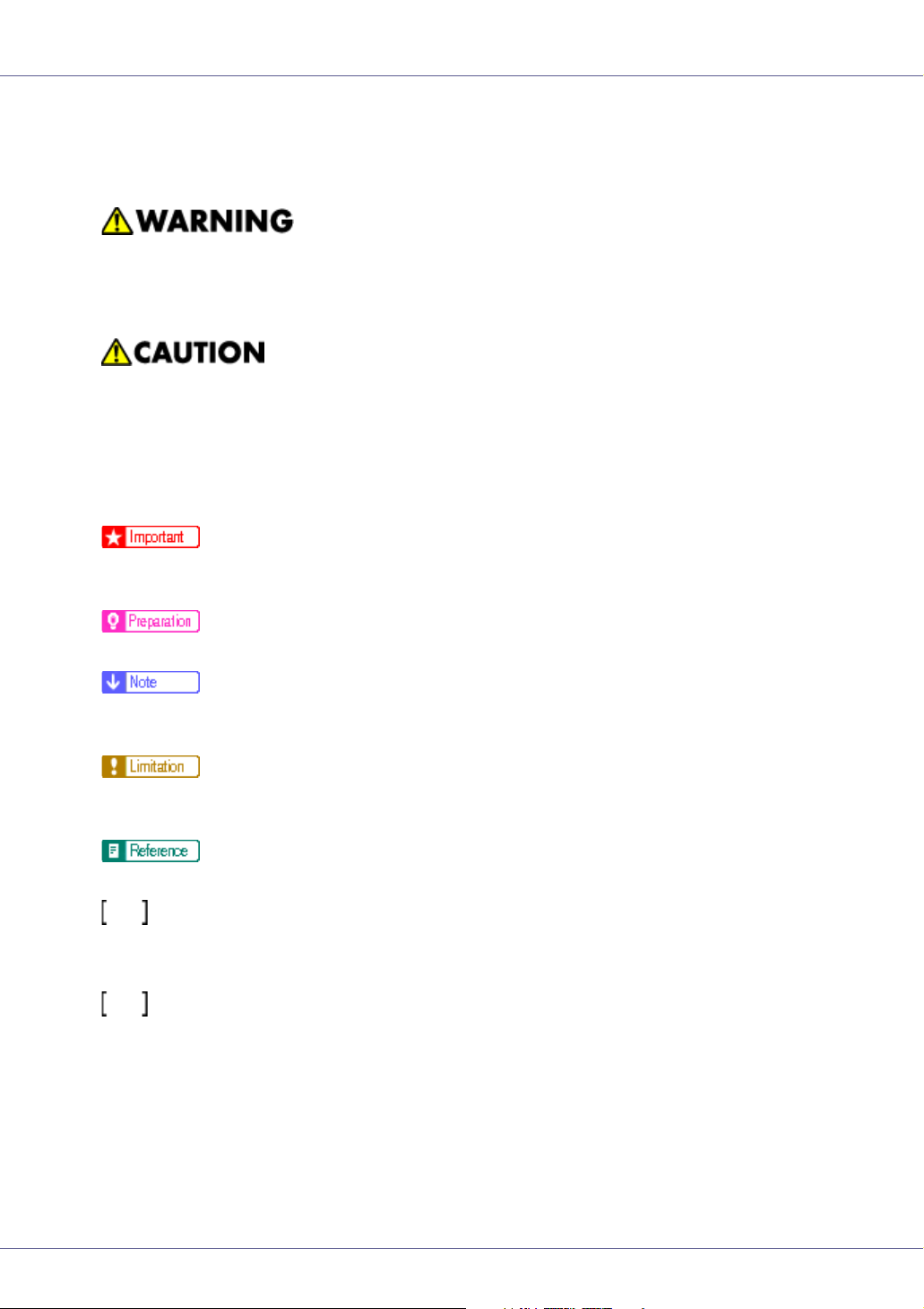
The following set of symbols is used in this manual.
This symbol indicates a potentially hazardous situation that might result in death
or serious injury when you misuse the machine without following the instructions
under this symbol. Be sure to read the instructions, all of which are described in
the Safety Information section.
This symbol indicates a potentially hazardous situation that might result in minor
or moderate injury or property damage that does not involve personal injury
when you misuse the machine without following the instructions under this symbol. Be sure to read the instructions, all of which are described in the Safety Information section.
* The statements above are notes for your safety.
If this instruction is not followed, paper might be misfed, originals might be damaged, or data might be lost. Be sure to read this.
This symbol indicates information or preparations required prior to operating.
This symbol indicates precautions for operation, or actions to take after abnormal
operation.
This symbol indicates numerical limits, functions that cannot be used together,
or conditions in which a particular function cannot be used.
This symbol indicates a reference.
Keys that appear on the machine's display.
Keys and buttons that appear on the computer's display.
Keys built into the machine's control panel.
Keys on the computer's keyboard.
5
Page 6
Paper and Other Media
Paper and Other Media Supported by This
Printer
This section describes the type, size, feed direction, and maximum amount of
paper that can be loaded into each tray.
❒ The following symbols and terminology are used to represent the feed direc-
tion.
In this manual On the display Paper feed direction
L ← (Feed direction)
K ← (Feed direction)
A4 (210 × 297)
8 1/2 × 11
A4 (297 × 210)
11 × 8 1/2
Short-edge feed direction
Long-edge feed direction
❒ Be careful of the paper feed direction. The direction is determined based on
paper size.
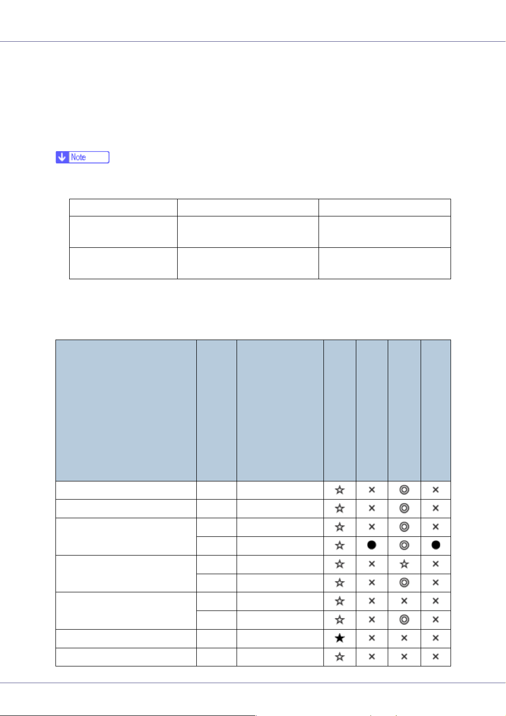
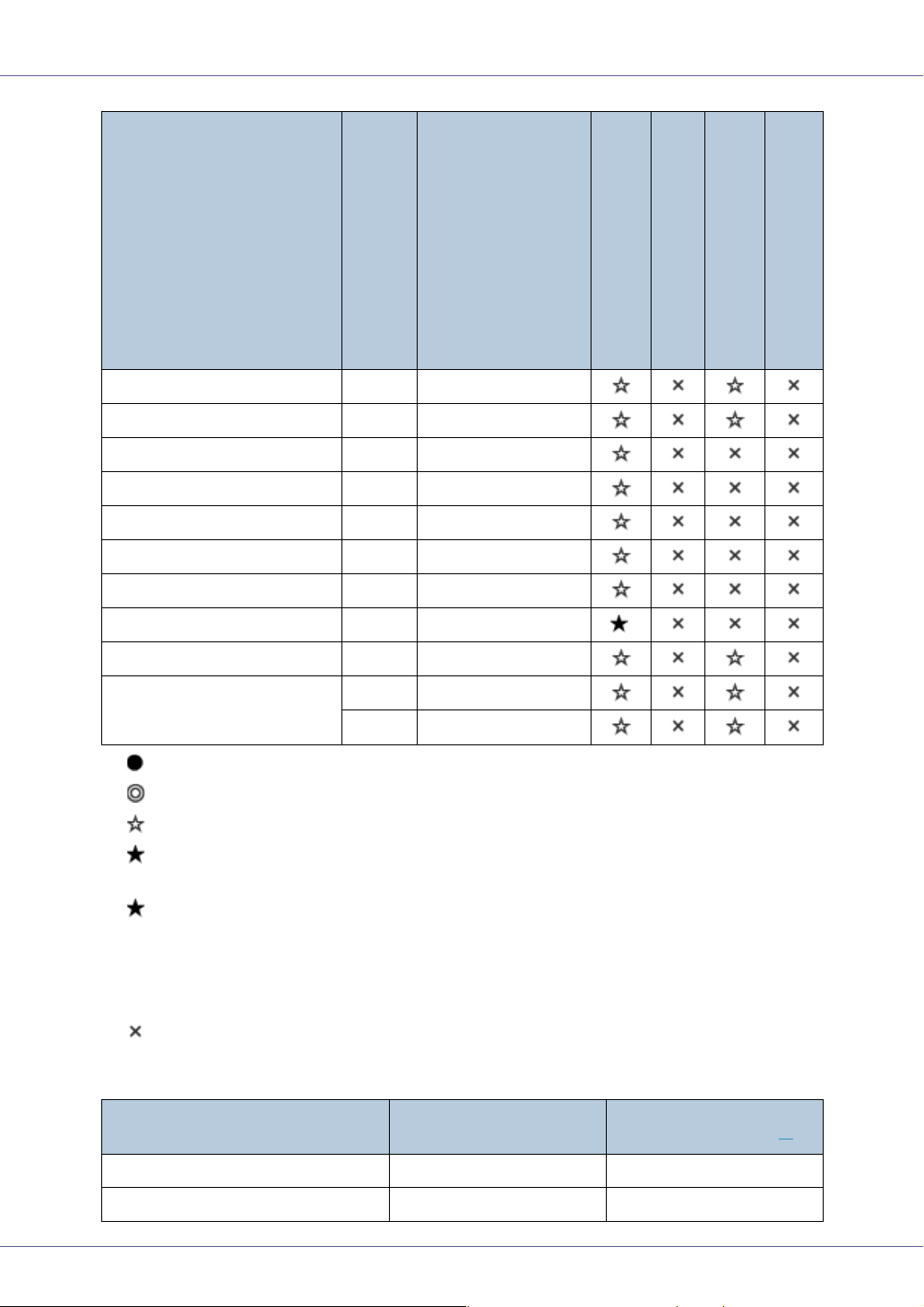
❖ Input Paper Sizes (Metric version)
Feed direction
A3 L 297 × 420
B4 L 257 × 364
Size (mm)
Bypass tray
Paper tray (Tray 1)
Paper tray (Tray 2)
Paper feed unit (Tray 3/4)
2000-sheet Large Capacity Tray
A4 L 210 × 297
K 297 × 210
B5 L 182 × 257
K 257 × 182
A5 L 148 × 210
K 210 × 148
B6 L 128 × 182
A6 L 105 × 148
G1307528_1.00 Copyright © 2005 6
Page 7
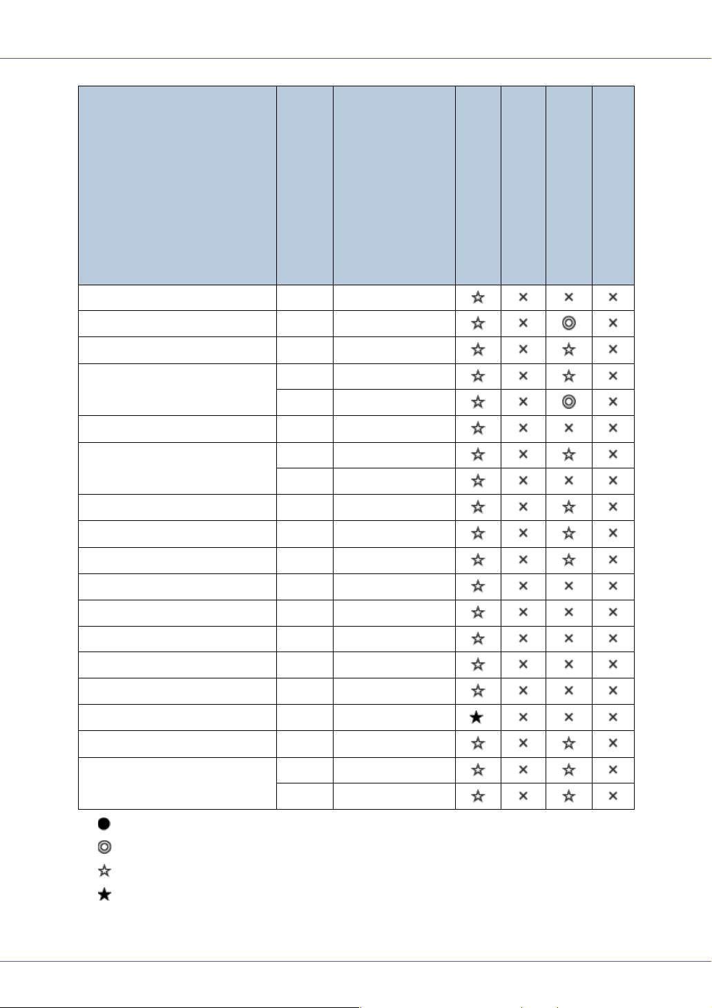
Paper and Other Media
Feed direction
Size (mm)
12” × 18” L 305 × 457
DLT (11” × 17”) L 279 × 432
Legal (LG, 8
Letter (LT, 8
1
/2” × 14”)
1
/2” × 11”)
L 216 × 356
L 216 × 279
K 279 × 216
1
5
/2” × 81/2”
Executive (Exec., 7
1
/4” × 101/2”)
L 140 × 216
L 184 × 276
K 276 × 184
Folio (8
1
/4” × 13”)
Foolscap (F4, 8
1
/2” × 13”)
L 210 × 330
L 216 × 330
F/GL (8” × 13”) L 203 × 330
1
Com10 Env (9
/2” × 41/8”)
C5 (9.02” × 6.38”)
C6 (6.38” × 4.49”)
K 241.3 × 104.8
K 229 × 162
K 162 × 114
DL Env (8.66” × 4.33”) K 220 × 110
Bypass tray
Paper tray (Tray 1)
Paper tray (Tray 2)
Paper feed unit (Tray 3/4)
2000-sheet Large Capacity Tray
1
Monarch (7
/2” × 37/8”)
Custom Size - -
8K (101/2” × 15.35”)
1
16K (7.68” × 10
/2”)
K 190.5 × 98.4
*
L 267 × 390
L 195 × 267
K 267 × 195
• The size is exclusive.
• The size is supported and the printer selects it automatically.
• The size is supported, but it should be selected using the control panel.
• The size is supported, but it should be set as a custom size using the control panel.
7
Page 8
Paper and Other Media
*
•
The supported size is approximately 90 - 305 mm in width, and 148 - 457
mm in length. The supported size may differ depending on the printer language you use. Set as a custom size setting using the control panel.
When using the RPCS
TM
printer driver, sheets of up to 1260 mm(600 × 600
dpi, 1200 × 600 dpi) in length can be set.
• The size is not supported.
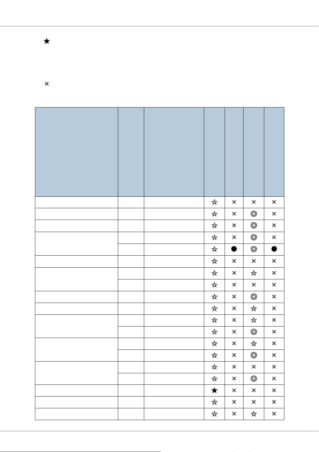
❖ Input Paper Sizes (Inch version)
Feed direction
Size (inch)
12” × 18” L 12” × 18”
DLT (11” × 17”) L 11” × 17”
Legal (LG) L
Letter (LT) L
K
1
/2” × 81/2”
5
L
Executive (Exec.) L
K
1
8
/2” × 14”
1
8
/2” × 11”
1
11” × 8
/2”
51/2” × 81/2”
1
7
/4” × 101/2”
1
/2” × 71/4”
10
A3 L 11.26” × 16.54”
B4 L 10.12” × 14.33”
A4 L 8.26” × 5.83”
K 5.83” × 8.26”
B5 L 7.17” × 10.12”
K 10.12” × 7.17”
A5 L 5.83” × 8.26”
Bypass tray
Paper tray (Tray 1)
Paper tray (Tray 2)
Paper feed unit (Tray 3/4)
2000-sheet Large Capacity Tray
K 8.26” × 5.83”
B6 L 5.04” × 7.17”
A6 L 4.13” × 5.63”
Folio L
13” × 8
1
/4”
8
Page 9
Paper and Other Media
Feed direction
Foolscap F4 K
F/GL K 13” × 8”
Com10 Env K
C5 K 9.02” × 6.38”
C6 K 6.38” × 4.49”
DL Env K 8.66” × 4.33”
Monarch K
Custom Size - -
8K L
16K L
K
Size (inch)
1
13” × 8
9
71/2” × 37/8”
10
7.68” × 10
10
/2”
1
/2” × 41/8”
1
/2” × 15.35”
1
/2” × 7.68”
Bypass tray
1
/2”
Paper tray (Tray 1)
*
Paper tray (Tray 2)
Paper feed unit (Tray 3/4)
2000-sheet Large Capacity Tray
• The size is exclusive.
• The size is supported, and the printer selects it automatically.
• The size is supported, but it should be selected using the control panel.
• The size is supported, but it should be set as a custom size using the control panel.
*
The supported size is approximately 3.5 - 12.01 inch in width, and 5.8 - 18
•
inch in length. The supported size may differ depending on the printer language you use. Set as a custom size setting using the control panel.
When using the RPCS
TM
printer driver, sheets of up to 49.61 inch(600 × 600
dpi, 1200 × 600 dpi) in length can be set.
• The size is not supported.
❖ Paper weight and number of sheets to be set
Supported paper weight
Tray 1
Tray 2
60 - 105 g/m
60 - 105 g/m
Maximum number of
sheets (plain paper)
2
(16 - 28 lb.) 500 (80 g/m2, 20 lb.)
2
(16 - 28 lb.) 500 (80 g/m2, 20 lb.)
*1
9
Page 10
Paper and Other Media
Maximum number of
sheets (plain paper)
Bypass tray
Paper Feed Unit Type 7300 (500 × 1)
Paper Feed Unit Type 7300 (500 × 2)
Paper Bank Type 7300
Supported paper weight
2
60 - 163 g/m
60 - 105 g/m
60 - 105 g/m
(14 - 42 lb.) 100 (80 g/m2, 20 lb.)
2
(16 - 28 lb.) 500 (80 g/m2, 20 lb.)
2
(16 - 28 lb.) 1000 (80 g/m2, 20 lb.)
60 - 105 g/m2 (16 - 28 lb.) 2000 (80 g/m2, 20 lb.)
(2000-sheet large capacity tray)
SR960 (2 tray finisher)
*1
Check that the top of the stack is not higher than the limit mark inside the tray.
60 - 105 g/m
2
(16 - 28 lb.) 2000 (80 g/m2, 20 lb.)
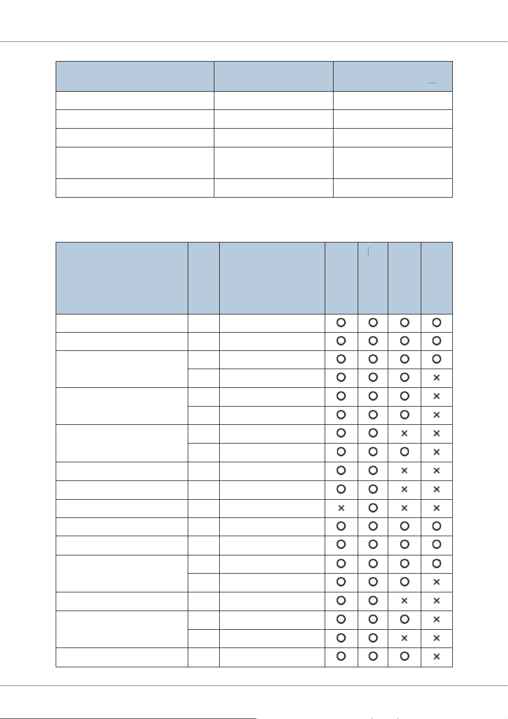
❖ Output Paper Sizes (Metric version)
*1
Feed direction
A3 L 297 × 420
B4 L 257 × 364
Size (mm)
Standard tray
External tray
*1
2 tray finisher
Booklet finisher
A4 L 210 × 297
K 297 × 210
B5 L 182 × 257
K 257 × 182
A5 L 148 × 210
K 210 × 148
B6 L 128 × 182
A6 L 105 × 148
12” × 18” L 305 × 457
DLT (11” × 17”) L 279 × 432
Legal (LG, 8
Letter (LT, 8
1
/2” × 14”)
1
/2” × 11”)
L 216 × 356
L 216 × 279
K 279 × 216
1
/2” × 81/2”
5
Executive (Exec., 7
1
10
/2”)
1
/4” ×
L 140 × 216
L 184 × 276
K 276 × 184
Folio (8
1
/4” × 13”)
L 210 × 330
10
Page 11
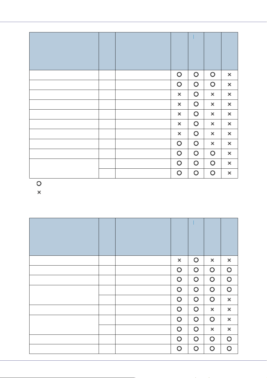
Paper and Other Media
*1
Foolscap (F4, 81/2” × 13”)
Feed direction
L 216 × 330
Size (mm)
F/GL (8” × 13”) L 203 × 330
Com10 Env (9
1
/2” × 41/8”)
K 241.3 × 104.8
C5 (9.02” × 6.38”) K 229 × 162
C6 (6.38” × 4.49”) K 162 × 114
DL Env (8.66” × 4.33”) K 220 × 110
Monarch (7
1
/2” × 37/8”)
K 190.5 × 98.4
Custom Size - -
1
8K (10
/2” × 15.35”)
16K (7.68” × 10
1
/2”)
L 267 × 390
L 195 × 267
K 267 × 195
• The size is supported.
• The size is not supported.
*1
The external tray does not support duplex printing.
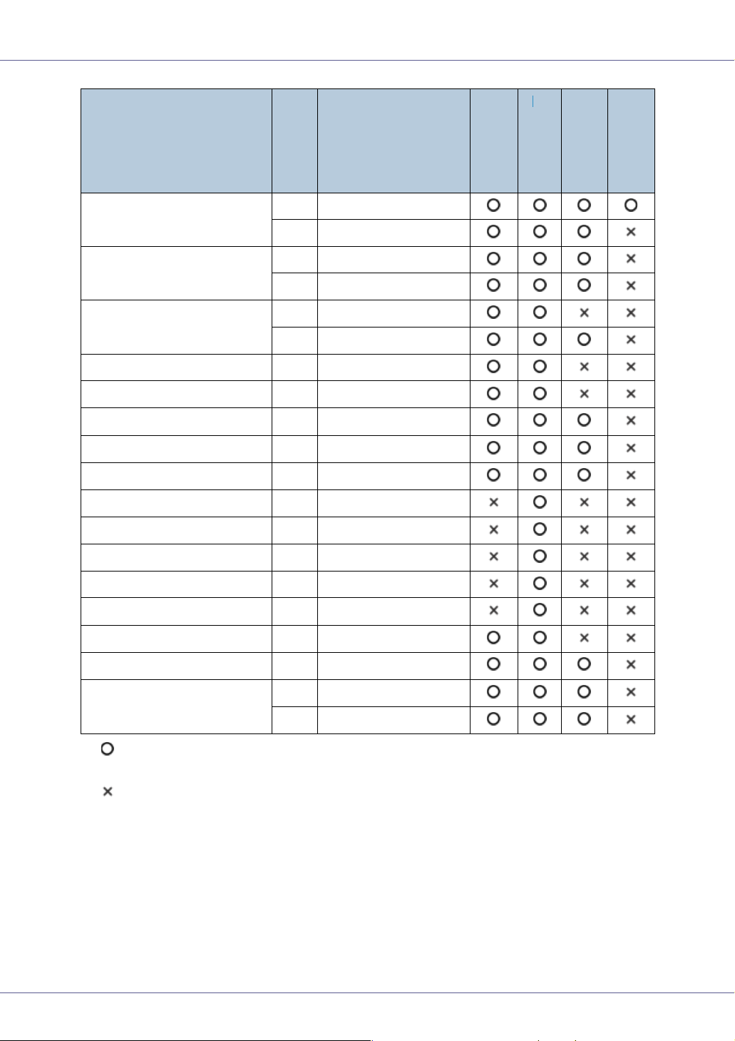
❖ Output Paper Sizes (Inch version)
Standard tray
External tray
2 tray finisher
Booklet finisher
Feed direction
Size (inch)
12” × 18” L 12” × 18”
DLT (11” × 17”) L 11” × 17”
Legal (LG) L
Letter (LT) L
K
1
/2” × 81/2”
5
L
Executive (Exec.) L
K
1
/2” × 14”
8
1
/2” × 11”
8
1
11” × 8
/2”
51/2” × 81/2”
1
/4” × 101/2”
7
1
10
/2” × 71/4”
A3 L 11.26” × 16.54”
B4 L 10.12” × 14.33”
*1
Standard tray
External tray
2 tray finisher
Booklet finisher
11
Page 12
Paper and Other Media
*1
Feed direction
Size (inch)
A4 L 8.26” × 5.83”
K 5.83” × 8.26”
B5 L 7.17” × 10.12”
K 10.12” × 7.17”
A5 L 5.83” × 8.26”
K 8.26” × 5.83”
B6 L 5.04” × 7.17”
A6 L 4.13” × 5.63”
Folio L
Foolscap F4 L
1
/4” × 13”
8
1
/2” × 13”
8
F/GL L 8” × 13”
Com10 Env K
1
/2” × 41/8”
9
C6 K 6.38” × 4.49”
C5 K 9.02” × 6.38”
DL Env K 8.66” × 4.33”
Monarch K
1
/2” × 37/8”
7
Standard tray
External tray
2 tray finisher
Booklet finisher
Custom Size - -
8K L
16K L
K
1
/2” × 15.35”
10
7.68” × 10
1
/2” × 7.68”
10
1
/2”
• The size is supported and it should be set using the control panel. There is
no dial in the tray.
• The size is not supported.
*1
The external tray does not support duplex printing.
12
Page 13

Paper and Other Media
Paper Recommendations
Loading Paper
❒ Do not use ink-jet printer paper because it may stick to the fusing unit and
cause a paper misfeed.
❒ When printing on OHP transparencies that have a print side, load them with
the print side over on the bypass tray. Not taking this precaution may cause
them to stick to the fusing unit and cause misfeeds.
❒ Set the paper as described below
• Tray 1, Tray 2: Print side facing up
• Bypass Tray: Print side facing down
• Paper Feed Unit (Option): Print side facing down
❒ Print quality cannot be guaranteed if paper other than the ones recommended
is used. For more information about recommended paper, contact your sales
or service representative.
❒ Do not use paper that has already been printed onto by other printers.
Storing Paper
• Paper should always be stored properly. Improperly stored paper might result
in poor print quality, paper misfeeds, or printer damage. Recommendations
are as follows:
• Avoid storing paper in humid areas.
• Avoid exposing paper to direct sunlight.
• Store on a flat surface.
• Keep paper in the package in which the paper came.
Types of Paper and Other Media
Plain Paper
Paper thickness
60 - 105 g/m
• [Normal]: 60 - 90 g/m
• [MidThick]: 91 - 105 g/m
2
(16 - 28 lb.)
2
(16 - 24 lb.)
2
(24.2 - 28 lb.)
13
Page 14
Paper and Other Media
Printer setup Make the following two settings using the control panel:
• Press [Paper Input] menu, [Paper Type], and then [Plain Paper].
• Press [Maintenance] menu, [Plain Paper] and then [Normal] or
[MidThick].
Printer driver setup Click [Plain] or [Plain & Recycled] in the [Type:] list.
Enabled paper feeding tray Any input tray can be used.
Number of sheets that can
be set
Both-sided printing Possible
Additional cautions When printing on the reverse side of plain paper that is already
• Tray 1/2: 500 × 2
• Paper Feed Unit Type 7300 (500×1): 500
• Paper Feed Unit Type 7300 (500×2): 1000
• Paper Bank Type 7300: 2000
• Bypass Tray: 100
❒ Make sure paper is not stacked higher than the upper limit
mark (T) inside the tray. Make sure paper is not stacked higher
than the paper guides inside the bypass tray.
printed on, select [Plain:Dup.Back] from [Paper Type] using the control panel or printer driver.
Thick Paper
Paper thickness
Printer setup Make the following two settings using the control panel:
106 - 163 g/m
• Press [Paper Input] menu, [Paper Type], and then [Thick Paper].
• Press [Maintenance] menu, [Thick Paper], and then [Thick Paper 1]
- [Thick Paper 4].
2
(28.2 - 42 lb.)
❒ From [Thick Paper 1] to [Thick Paper 4] in the menu, select the
paper thickness according to the paper you are loading.
Printer driver setup Click [Thick] in the [Type:] list.
Enabled paper feeding tray Bypass tray
❒ Make sure paper is not stacked higher than the paper guides
inside the bypass tray.
Both-sided printing Not possible
Additional cautions • Print speed is slightly slower than when using plain paper.
• When printing on the reverse side of thick paper that is already
printed on, select [Thick:Dup.Back] from [Paper Type] using the
control panel or printer driver.
14
Page 15
Paper and Other Media
OHP transparencies
Printer setup Press [Paper Input] menu, [Paper Type], and then [Transparency] on
the control panel.
Printer driver setup Click [Transparency] in the [Type:] list.
Enabled paper feeding tray Bypass tray
Number of sheets that can
be set
Both-sided printing Not possible
Additional cautions • Print speed for OHP transparencies is slower than for plain pa-
100
❒ Make sure paper is not stacked higher than the paper guides
inside the bypass tray.
per.
• Paper settings can be set using the printer driver. Setting the
paper sizes using the display panel is not necessary when it is
set by the printer driver.
• Paper size settings set using the printer driver have priority
over those set using the machine's display panel.
• When the printer driver is not used, make settings using the
display panel.
• Select the [Maintenance] menu. Press [4C.Graphic Mode], [Text
Priority], and then print.
Special Paper
Printer setup Make the following two settings using the control panel:
• Press [Paper Input] menu, [Paper Type], and then [Special Paper]
on the control panel.
• Press [Maintenance] menu, [Special Paper], and then [Special Pa-
per 1] - [Special Paper 4].
❒ From [Special Paper 1] to [Special Paper 4] in the menu, select
the paper type according to the paper you are loading.
Printer driver setup Click [Special Paper] in the [Type:] list.
Enabled paper feeding tray Any input tray can be used.
❒ Make sure paper is not stacked higher than the upper limit
mark (T) inside the tray. Make sure paper is not stacked higher
than the paper guides inside the bypass tray.
Both-sided printing Possible
Additional cautions Print speed for special paper is slower than for plain paper.
15
Page 16
Paper and Other Media
Envelopes
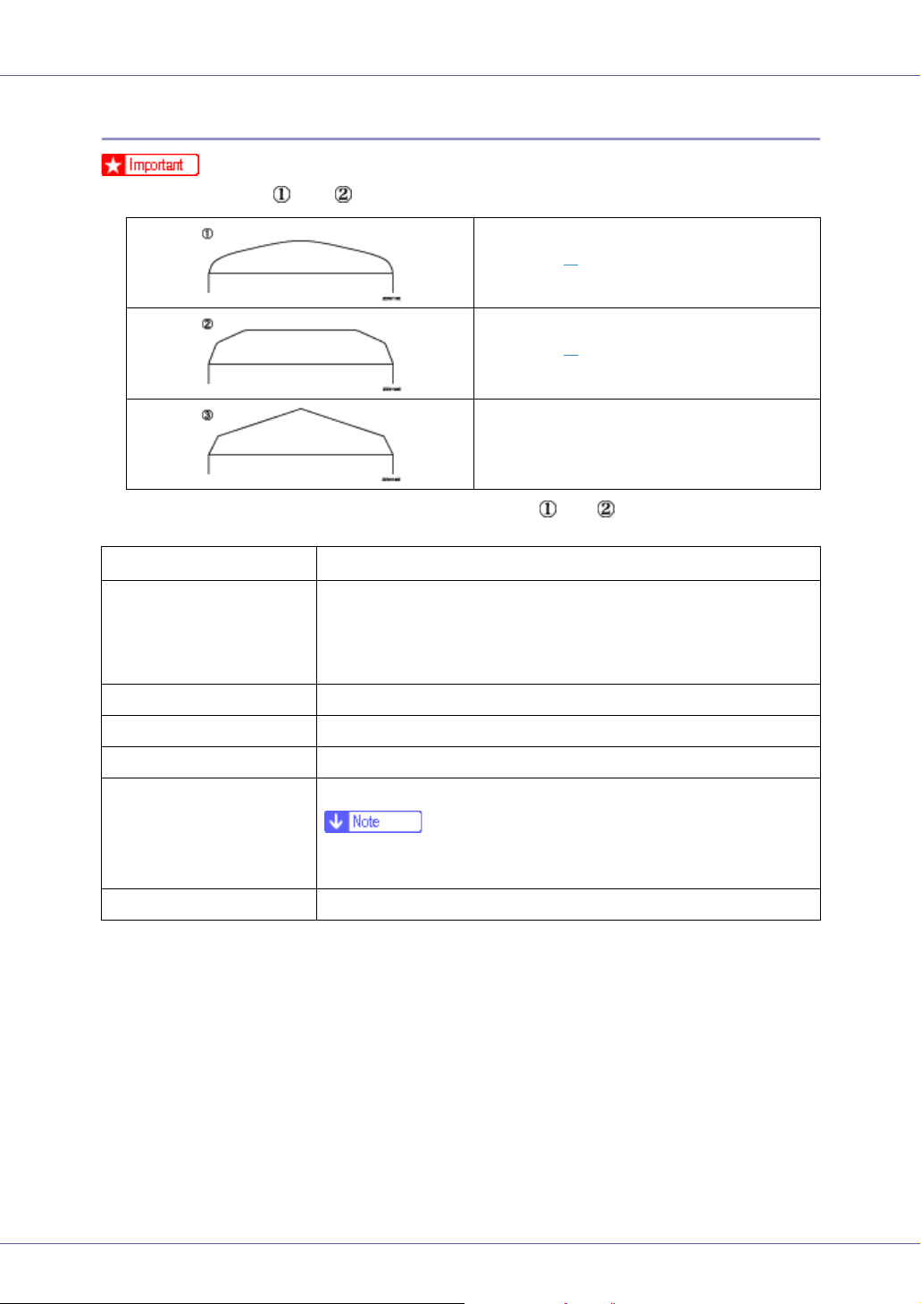
❒ Only envelopes and as shown below are supported.
Supported
Supported
*1
*1
Not supported
*1
Misfeeds might also occur when using envelopes and depending on the length
and shape of the flaps.
Paper thickness
Recommended weight and
size
72 - 90 g/m
• Metric version
72 g/m
• Inch version
24 lb, 3
Printer setup Press [Paper Input] menu, [Paper Type], and then [Thick Paper].
Printer driver setup Click [Thick] in the [Type:] list.
Enabled paper feeding tray Bypass tray
2
(19 - 24 lb.)
2
, 114 × 162 mm (C6 Env)
7
/8” × 7 1/2” (Monarch)
Enabled paper feeding tray 10
❒ Make sure paper is not stacked higher than the paper guides
inside the bypass tray.
Both-sided printing Not possible
16
Page 17
Paper and Other Media
Additional cautions • Check the print side is facing up.
• Check there is no air in the envelopes before loading.
• For better print quality, we recommend the right, left, top, and
bottom print margins to be at least 15 mm (0.6”) each.
• Load only one size and type of envelope at a time.
• When loading envelopes, be sure to unfold the flaps and position them opposite to the paper feed direction.
• Before loading envelopes, flatten their leading edges (the edge
going into the printer) by running a pencil or ruler across them.
• Some kinds of envelope might cause misfeeds, wrinkles or
print poorly.
• Print quality on envelopes may be uneven if parts of an envelope have differing thicknesses. Print one or two envelopes to
check print quality.
Paper not supported by this printer
Avoid using the following paper as they are not supported by this printer.
• Paper meant for an ink-jet printer
• Bent, folded, or creased paper
• Curled or twisted paper
• Torn paper
• Wrinkled paper
• Damp paper
• Paper that is dry enough to emit static electricity
• Paper that has already been printed onto, except a preprinted letterhead.
Malfunctions are especially likely when using paper printed on by other than
a laser printer (e.g. monochrome and color copiers, ink-jet printers, etc.)
• Special paper, such as thermal paper, aluminum foil, carbon paper and conductive paper
• Paper whose weight is heavier or lighter than the limitation
• Paper with windows, holes, perforations, cutouts, or embossing
17
Page 18
Paper and Other Media
• Adhesive label paper on which glue or base paper is exposed
• Paper with clips or staples
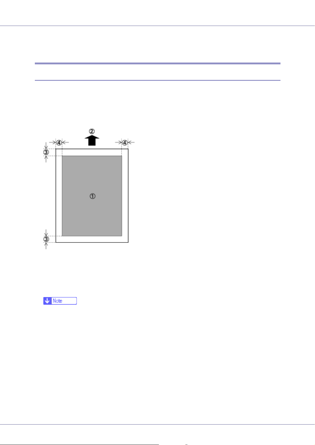
Print Area
The following shows the print area for this printer. Be sure to set the print margins
correctly by the application.
❖ Paper
A Print area
B Feed direction
C Approx. 4.2 mm (0.17 inches)
D Approx. 4.2 mm (0.17 inches)
❒ Print area may vary depending on paper size, printer language, and printer
driver settings.
❒ If you load paper larger than A3L in the bypass tray, hold it steady so it
feeds properly. Paper feed accuracy and print quality may vary according
to paper thickness and width. Do a test print to check the paper you want
to use gives satisfactory results.
❒ The maximum length of the print area is 457 mm (18”) in the paper feed
direction (at 1200×1200 dpi). If paper exceeding 457 mm (18”) in the paper
feed direction is used, the machine may not print properly.
18
Page 19
Paper and Other Media
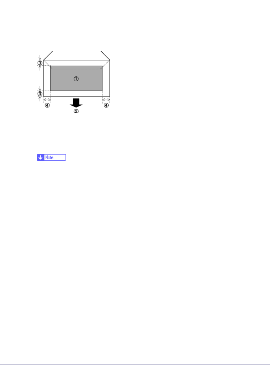
❖ Envelope
A Print area
B Feed direction
C Approx. 4.2 mm (0.17 inches)
D Approx. 4.2 mm (0.17 inches)
❒ The print area may vary depending on the paper size, printer language and
printer driver settings.
19
Page 20
Paper and Other Media
Loading Paper
Load paper and change the paper size in tray 1, tray 2, and the optional paper
feed unit by following the procedures below.
❒ Tray 1 uses only letter size paper (11 × 81/2 K) exclusively. Load letter size
paper (11 × 8
❒ The 2000-sheet large capacity tray uses only letter size paper (11 × 8
exclusively. Load A4 paper at all times.
❒ If you want to load A4 K paper in tray 1 and the optional 2000-sheet large
capacity tray, contact your sales or service representative.
See p.6 “Paper and Other Media Supported by This Printer”, for details about
paper to be loaded in the paper tray and optional Paper Feed Unit Type 7300.
1
/2) at all times.
1
/2 K)
Loading Paper in Tray 1/2 and the optional paper feed unit
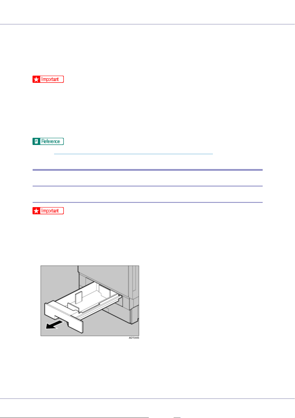
Loading Paper in Tray 1
❒ Tray 1 uses only letter size paper (11 × 81/2 K) paper exclusively. Load letter
size paper at all times.
❒ If you want to load A4 K paper in tray 1, contact your sales or service repre-
sentative.
A Slowly pull out the paper tray, until it stops.
20
Page 21
Paper and Other Media
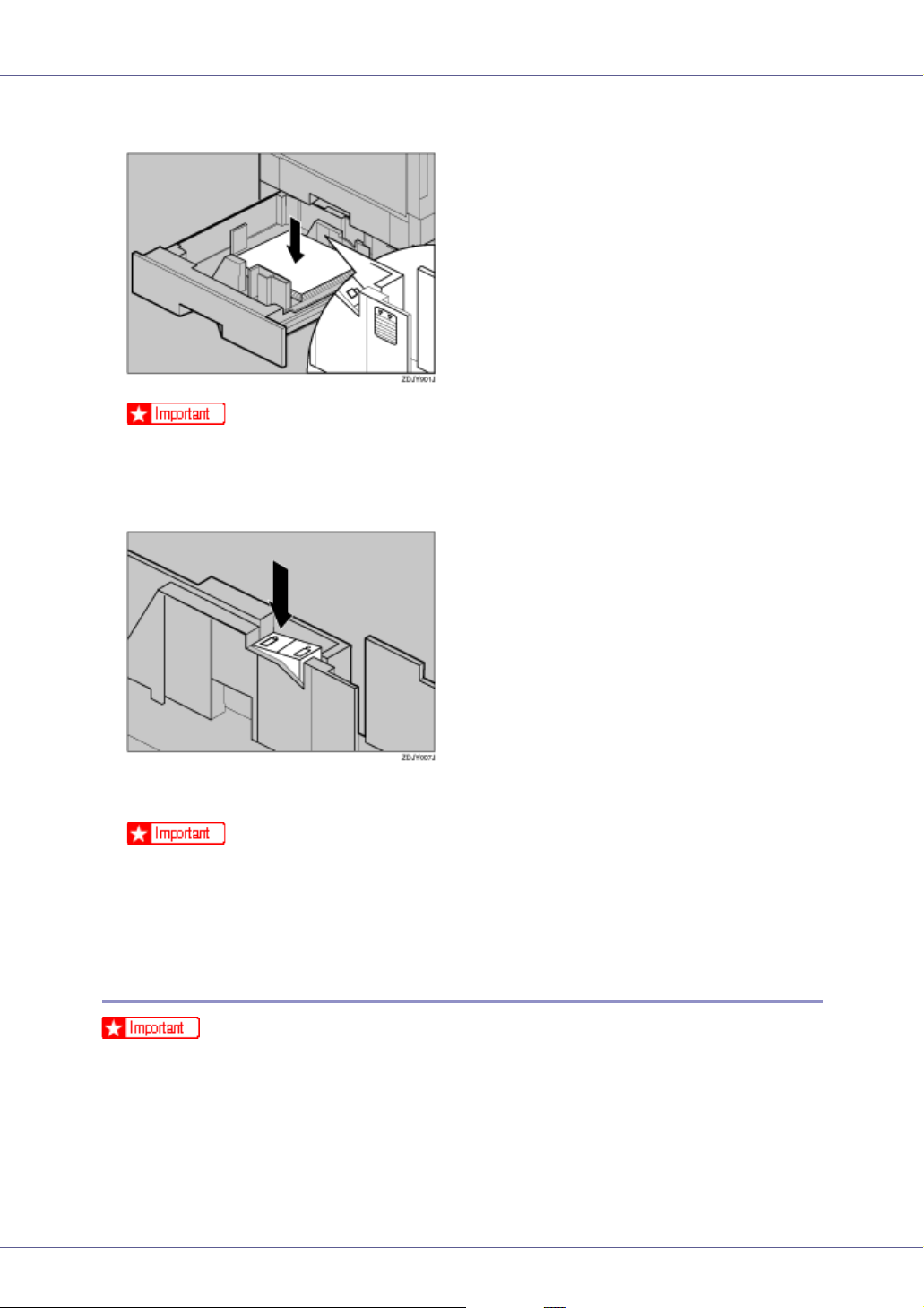
B Load paper into the tray with the print side down.
❒ Check that the top of the stack is not higher than the limit mark inside the
tray.
C Carefully slide the paper tray into the printer, until it stops.
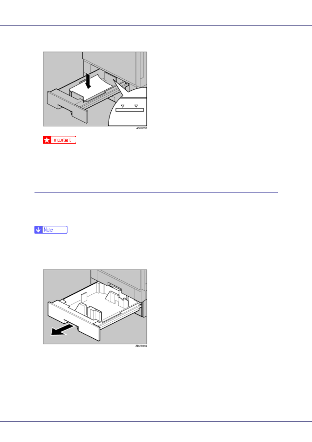
Loading Paper in Tray 2 and Paper Feed Unit Type 7300
Paper of different sizes can be loaded in tray 2 and the 500- and 1000-sheet paper feed units (optional) by adjusting the positions of the side and end guides.
This section describes loading paper in tray 2.
❒ If the side and end guides are in the right positions for the paper to be loaded,
they do not have to be adjusted.
A Slowly slide the paper tray out, until it stops.
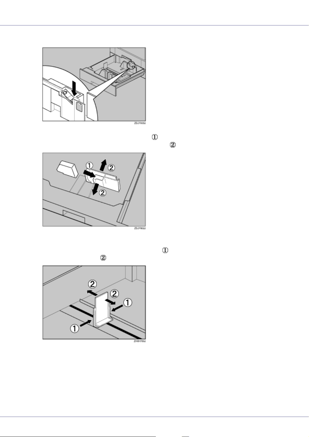
B Adjust the side guide according to the size and orientation of the paper
as follows:
21
Page 22
Paper and Other Media
Release the side guide lock.
C Press the side guide green lever ( ), adjust the position of the guide by
moving it in the direction of the arrow ( ).
D Adjust the end guide according to the size and orientation of the paper
by gripping both edges of the guide ( ), and then moving it in the direction of the arrow ( ).
22
Page 23
Paper and Other Media
E Align all four sides of the paper stack, and then load it in the tray.
❒ Check that the top of the stack is not higher than the limit mark inside the
tray.
F Make sure the paper is fixed in place, and then lock the side guide.
G Slowly slide the paper tray back until it stops.
❒ Do not slide the paper tray in with force. If you do, the front and side guides
might move.
❒ Be sure to adjust the side guides to the paper size, or misfeeds might oc-
cur.
Loading Paper in Paper Bank Type 7300 (2000-sheet Large Capacity Tray)
❒ The 2000-sheet large capacity tray uses only letter size paper (11 × 81/2 K)
exclusively. Load letter size paper at all times.
❒ If you want to load A4 K paper in the 2000-sheet large capacity tray, contact
your sales or service representative.
23
Page 24
Paper and Other Media
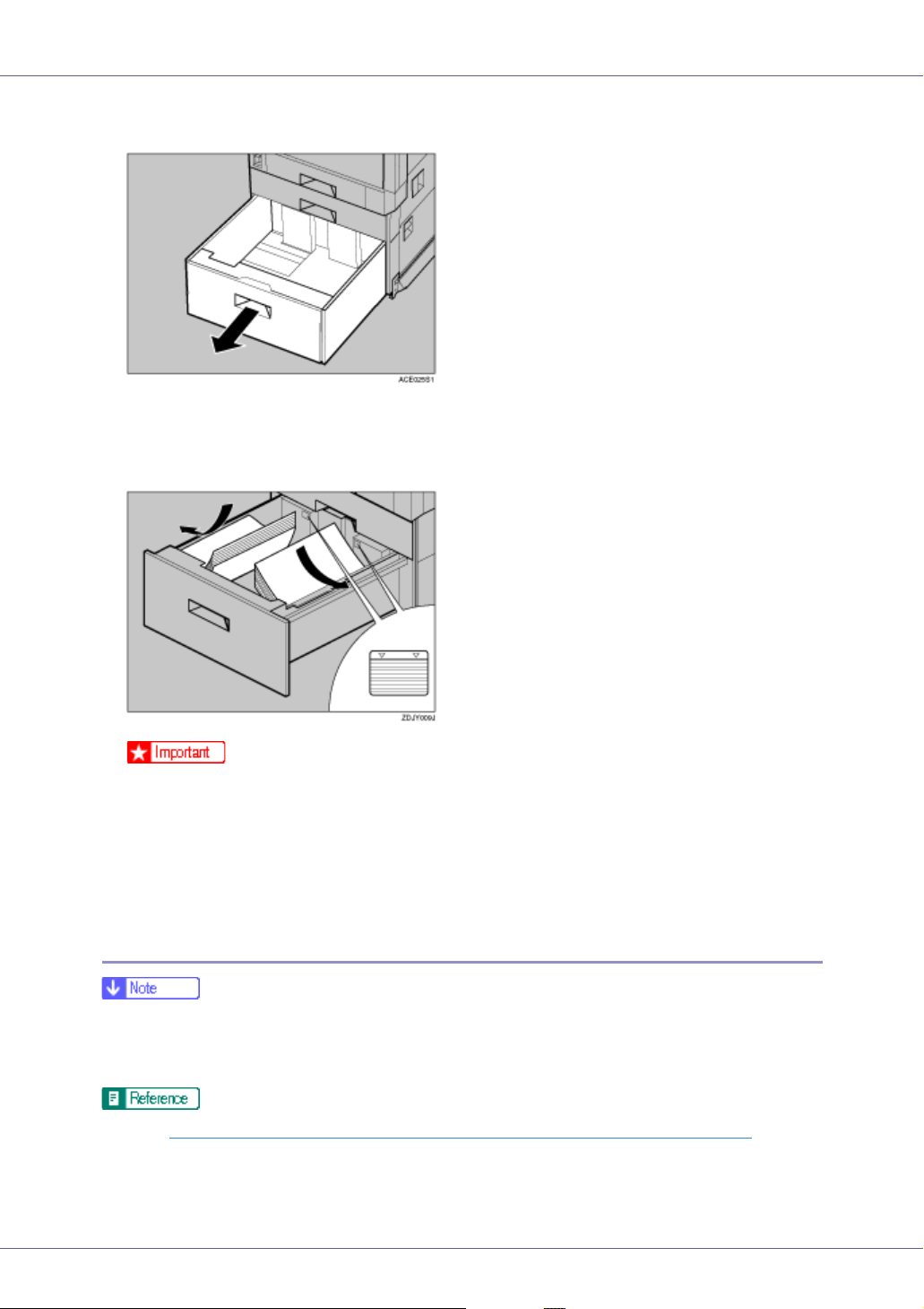
A Slowly pull out the paper tray, until it stops.
B With the print side down, align all four sides of the two paper stacks, and
then load them next to each other in the tray. Each side has a limit of
1,000 sheets.
❒ Align the paper and load the stacks against the left and right walls, or mis-
feeds might occur.
❒ Check that the top of the stack is not higher than the limit mark inside the
tray.
C Slowly push in the paper tray until it stops.
If you load a paper size that is not selected automatically
❒ Paper sizes not selected automatically are B4L, A4L, B5L, 71/4 × 101/2L,
8 × 13L, 8
16K (10
See p.21 “Loading Paper in Tray 2 and Paper Feed Unit Type 7300”, for details about how to load the paper.
1
/2 × 13L, 81/4 × 13L, 8K (101/2 × 15.35)L, 16K (7.68 × 101/2)L,
1
/2 × 7.68)K.
24
Page 25
Paper and Other Media
❒ Tray 1 uses only letter size paper (11 × 81/2 K) exclusively. Load letter size
paper at all times.
1
❒ 2000-sheet large capacity tray uses only letter size paper (11 × 8
sively. Load letter size paper at all times.
❒ If you want to load A4 K paper in tray 1 and the optional 2000-sheet large
capacity tray, contact your sales or service representative.
This section uses A4 (210 × 297) L as an example.
/2 K) exclu-
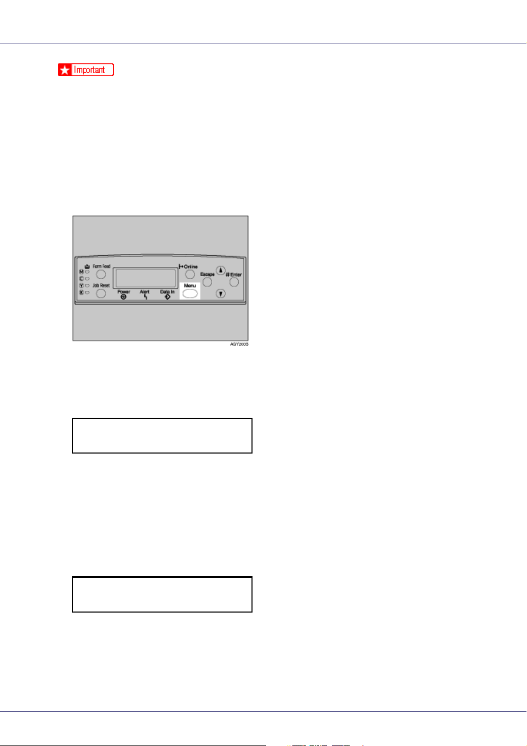
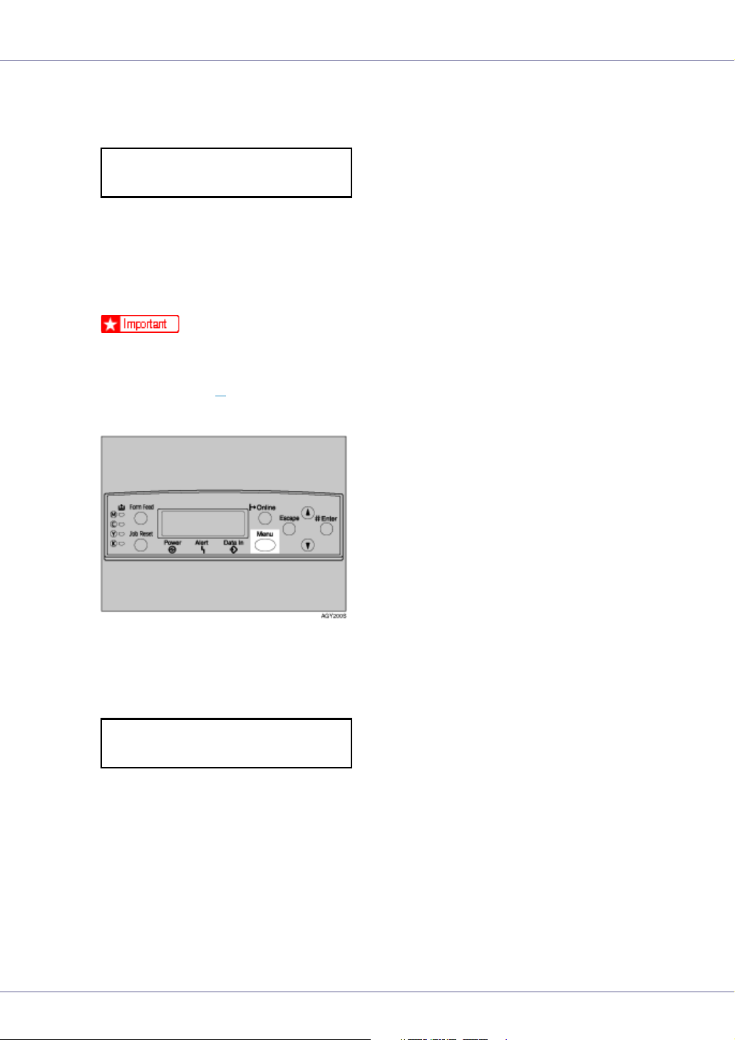
A Press the {Menu} key.
The [Menu] screen appears on the display.
B Press the {U} or {T} key to display [Paper Input], and then press the {#
Enter}.
Menu:
Paper Input
The paper selection menu appears.
C Press the {U} or {T}key to display [Tray Paper Size], and then press the {#
Enter} key.
The paper tray selection menu appears.
D Press the {U} or {T}key to display the target paper tray, and then press
the {# Enter} key.
Tray Paper Size:
Tray 2
The paper size selection menu appears.
25
Page 26
Paper and Other Media
E Press the {U} or {T} key to display the loaded paper size, and then
press the {# Enter} key.
Tray 2 :
*A4 (210 x 297)
After about two seconds, the display returns to the menu.
F Press the {Online} key.
The initial screen appears.
This completes the setting change.
❒ After printing on a paper size that is not selected automatically, if you want
to print on paper that is selected automatically again, reload the paper, proceed to step
, and return the setting to “Auto”.
G
G Press the {Menu} key.
The [Menu] screen appears on the display.
H Press the {U} or {T} key to display [Paper Input], and then press the {#
Enter} key.
Menu:
Paper Input
The paper selection menu appears.
I Press the {U} or {T}key to display [Tray Paper Size], and then press the {#
Enter} key.
The paper tray selection menu appears.
26
Page 27
Paper and Other Media
J Press the {U} or {T} key to display the target paper tray, and then press
the {# Enter} key.
Tray Paper Size:
Tray 2
The paper size selection menu appears.
K Press the {U} or {T} key to display [Auto], and then press the {# Enter}
key.
Tray 2
*Auto
After about two seconds, the display returns to the menu.
L Press the {Online} key.
The initial screen appears.
Specifying a paper type for Tray 1/2 and the optional paper feed unit
Improve printer performance by selecting the optimum paper type for the tray.
You can select from the following paper types:
• Plain Paper, Recycled Paper, Special Paper, Color Paper, Letterhead, Preprinted Paper
A Press the {Menu} key.
The [Menu] screen appears on the display.
B Press the {U} or {T} key to display [Paper Input], and then press the {#
Enter} key.
Menu:
Paper Input
The paper selection menu appears.
27
Page 28
Paper and Other Media
C Press the {U} or {T} key to display [Paper Type], and then press the {# En-
ter} key.
The paper tray selection menu appears.
D Press the {U} or {T} key to display the target paper tray, and then press
the {# Enter} key.
Paper Type:
Tray 2
The paper type selection menu appears.
E Press the {U} or {T} key to display the loaded paper type, and then
press the {# Enter} key.
Tray 2
*Recycled Paper
After about two seconds, the display returns to the menu.
F Press the {Online} key.
The initial screen appears.
Loading Paper in the Bypass Tray
Besides plain paper, you can use the bypass tray to load thick paper, envelopes,
OHP transparencies, paper longer than A3L, and paper that cannot be loaded
in the paper trays or paper feed unit.
• Set the size and direction of the loaded paper on the control panel or with the
printer driver. Make sure the settings do not conflict. Otherwise, the paper
may jam or the print quality may be affected.
❒ The bypass tray can accommodate sheets 90-305 mm(3.5”-12.01”) wide and
148-457 mm(5.8”-18”) long. However, the paper size must be set using the
control panel. When using the RPCS
mm(49.61”) in length can be set.
❒ If you load custom size paper or special paper, select the paper size using the
control panel. The RPCS
printer driver properties. The paper size selected using the printer driver overrides that selected using the control panel. See p.31 “
paper for the Bypass Tray”.
TM
printer driver can select the paper size using the
TM
printer driver, sheets of up to 1260
Specifying custom size
❒ If you load thick paper, OHP transparencies, or envelopes, make the settings
for thick paper or OHP transparencies using the control panel or printer driver.
See p.32 “
Specifying a paper type for the Bypass Tray”.
28
Page 29
Paper and Other Media
❒ The number of pages that can be loaded in the bypass tray differs depending
on paper type. Check that the top of the stack is not higher than the limit mark
inside the tray.
❒ When loading paper in the bypass tray, use L orientation if possible.
❒ When loading the bypass tray with paper that will be delivered into the top-left
tray, load the paper so the side you want to print on faces up.
❒ You cannot use the following functions when printing on paper loaded in the
bypass tray:
•Duplex Print
• Job Separation
• Staple/Punch
• Auto Tray Select
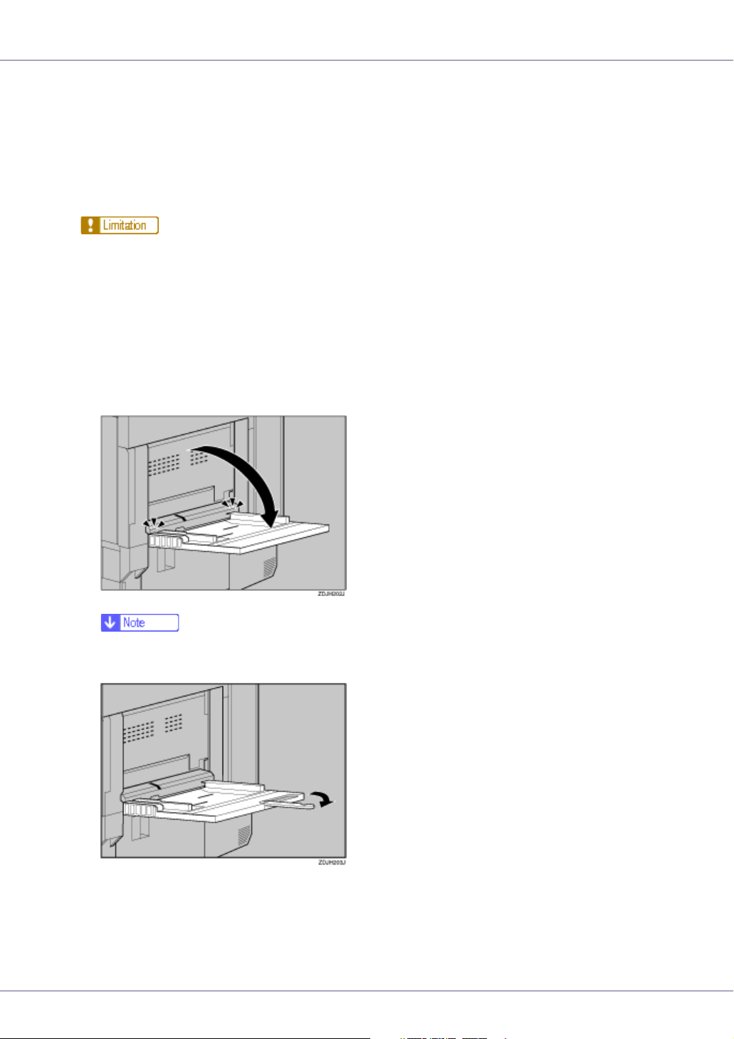
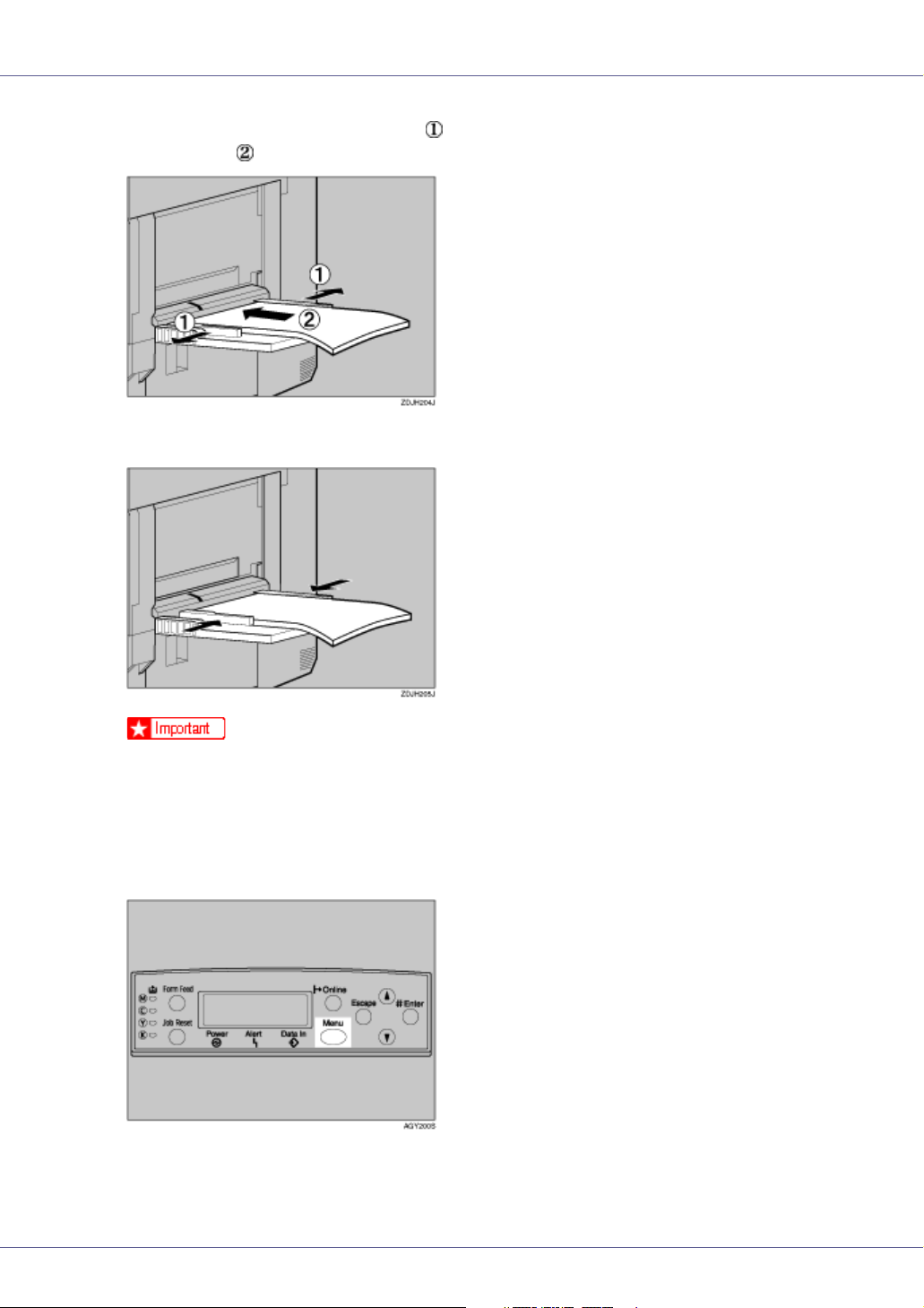
A Open the bypass tray.
❒ If you load A4 or larger size paper, pull out the bypass tray extension, and
then flip it open.
29
Page 30
Paper and Other Media
B Slide the side guides outward ( ), and then load paper print side up, un-
til it stops ( ).
C Adjust the side guides to fit the paper width.
❒ Check that the top of the stack is not higher than the limit mark inside the
tray.
❒ Shuffle the paper before loading the stack onto the tray, so multiple sheets
are not fed in together.
D Set the paper size using the control panel. Press the {Menu} key.
The [Menu] screen appears on the display.
30
Page 31

Paper and Other Media
E Press the {U} or {T} key to display [Paper Input], and then press the {#
Enter} key.
Menu:
Paper Input
The paper selection menu appears.
F Check [Bypass Size] appears, and then press the {# Enter} key.
The paper size selection menu appears.
G Press the {U} or {T} key to display the size and orientation of the paper
in the bypass tray.
Bypass Size
*11 x 17
After about two seconds, the display returns to the menu.
H Press the {Online} key.
The initial screen appears.
Specifying custom size paper for the Bypass Tray
❒ The paper size selected using the printer driver overrides that selected using
the control panel. You do not have to make settings using the control panel if
you already made them using the printer driver. However, when printing with
a printer driver other than the RPCS
tings using the control panel. For details about the printer driver, see Help.
❒ The printer cannot print from applications that do not support custom size pa-
per.
TM
printer driver, you must make the set-
A Press the {Menu} key.
The [Menu] screen appears on the display.
31
Page 32

Paper and Other Media
B Press the {U} or {T} key to display [Paper Input], and then press the {#
Enter}key.
Menu:
Paper Input
The paper selection menu appears.
C Check [Bypass Size] appears, and then press the {# Enter} key.
The paper size selection menu appears.
D Press the {U} or {T} key to display [Custom Size], and then press the {#
Enter} key.
E Press the {U} or {T} key to set the horizontal value, and then press the
{# Enter} key.
Custom Size:
Horiz. 8.50”
By pressing the key, the value increases or decreases by 0.01 inch. By pressing and holding the key, the value varies by 1 inch.
F Press the {U} or {T} key to set the vertical value, and then press the {#
Enter} key.
Custom Size:
Vert. 11.00”
After about two seconds, the display returns to the menu.
G Press the {Online} key.
The initial screen appears.
Specifying a paper type for the Bypass Tray
By selecting the paper type you want to load, the printer performs better. You can
select from the following paper types:
• Plain Paper, Recycled Paper, Special Paper, Color Paper, Letterhead, Preprinted Paper, OHP Transparencies, Thick Paper, Plain Paper (Duplex),
Thick Paper (Duplex)
❒ You cannot use the following functions when printing on paper loaded in the
bypass tray:
•Duplex Print
• Job Separation
32
Page 33

Paper and Other Media
• Staple, Punch
• Auto Tray Select
❒ Be sure to select the paper type when you load labels, thick paper, or OHP
transparencies in the bypass tray.
❒ When printing labels, select thick paper as the paper type.
A Press the {Menu} key.
The [Menu] screen appears on the display.
B Press the {U} or {T} key to display [Paper Input], and then press the {#
Enter} key.
Menu:
Paper Input
The paper selection menu appears.
C Press the {U} or {T} key to display [Paper Type], and then press the {# En-
ter} key.
The paper tray selection menu appears.
D Press the {U} or {T} key to display [Bypass Tray], and then press the {#
Enter} key.
The paper type selection menu appears.
E Press the {U} or {T} key to display the target paper type, and then press
the {# Enter} key.
Bypass Tray:
*Thick Paper
After about two seconds, the display returns to the menu.
33
Page 34

Paper and Other Media
F Press the {Online} key.
The initial screen appears.
Switching between Paper Trays
When paper of the same size is loaded in both the standard tray and the paper
feed unit (option), and when “Auto Tray Select” is set with the printer driver, paper will be fed from the standard tray when you start printing. To print on paper
loaded in the paper feed unit, switch the tray to be used to the paper feed unit
using “Tray Priority” in the “Paper Input” Menu.
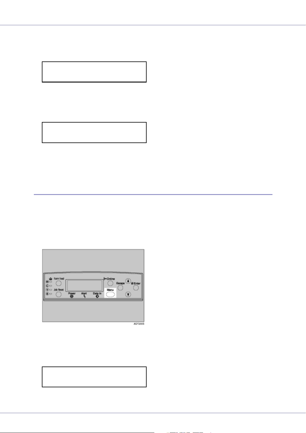
A Press the {Menu} key.
The [Menu] screen appears on the display.
B Press the {U} or {T} key to display [Paper Input], and then press the {#
Enter} key.
Menu:
Paper Input
The paper selection menu appears.
C Press the {U} or {T} key to display [Tray Priority], and then press the {#
Enter} key.
The paper tray selection menu appears.
D Press the {U} or {T} key to select the tray type you want to use, and
then press the {# Enter} key.
The following message appears on the display:
Tray Priority:
*Tray 2
E Press the {Online} key.
34
Page 35

Paper and Other Media
The initial screen appears.
35
Page 36

Replacing Consumables and Maintenance Kit
Using the Screwdriver
The screwdriver supplied is used for attaching options and is located inside the
front cover.
A Open the printer’s front cover, and then remove the provided screwdriv-
er.
B Insert the screw into the screwdriver.
By pushing the screw into the screwdriver, you can work without having to
worry about dropping the screw.
❒ After using the screwdriver, return it to its original position inside of the front
cover.
G1307528_1.00 Copyright © 2005 36
Page 37

Replacing Consumables and Maintenance Kit
Detaching and Reattaching the Options
This section describes how to detach or reattach optional finishers and how to
open and close the duplex reversal unit. Follow the procedure below when replacing various units or removing jammed paper.
Detaching the SR960 (2 Tray Finisher)
There are times when you may need to detach the 2 tray finisher from the printer
to remove misfed paper. This section describes how to detach the 2 tray finisher.
A Hold the handle at the top of the 2 tray finisher firmly using one hand,
pull the 2 tray finisher straight out, and let go when it stops.
The 2 tray finisher is detached from the printer.
B Use both hands to push it straight back in, and let go when it clicks into
place.
The 2 tray finisher is reattached to the printer.
❒ Be sure to attach the 2 tray finisher to the printer after closing the duplex
reversal unit. See p.38 “
Opening and Closing the Duplex Reversal Unit”.
37
Page 38

Replacing Consumables and Maintenance Kit
Detaching the SR950 (Booklet Finisher)
A Hold the release lever, and then pull out the booklet finisher.
The booklet finisher is detached from the printer.
B Attach the booklet finisher.
The booklet finisher is reattached to the printer.
Opening and Closing the Duplex Reversal Unit
There are times when you may need to detach the duplex reversal unit to remove
misfed paper. This section describes how to detach the duplex reversal unit.
A Push up the lock release button and leave it in place.
38
Page 39

Replacing Consumables and Maintenance Kit
B Lower the duplex reversal unit slowly until it stops.
❒ Open the duplex reversal unit after detaching the 2 tray finisher or the
booklet finisher from the printer. See p.37 “
Finisher)” or p.38 “Detaching the SR950 (Booklet Finisher)”.
❒ You do not have to remove the external tray even if the 2 tray finisher or
the booklet finisher is attached.
The duplex reversal unit is opened.
Detaching the SR960 (2 Tray
C Close the duplex reversal unit by raising it slowly using both hands, and
push it in, until it clicks into place.
The duplex reversal unit is closed.
❒ Attach the duplex reversal unit after closing the printer's upper left cover.
39
Page 40

Replacing Consumables and Maintenance Kit
Replacing the Toner Cartridge
• Do not incinerate spilled toner or used toner. Toner dust is flammable
and might ignite when exposed to an open flame.
• Disposal should take place at an authorized dealer or an appropriate
collection site.
• If you dispose of the used toner cartridges yourself, dispose of them
according to local regulations.
• Do not store toner, used toner, or toner containers in a place with an
open flame. The toner might ignite and cause burns or a fire.
• Keep toner (used or unused) and the toner cartridge out of reach of children.
• If toner or used toner is inhaled, gargle with plenty of water and move into
a fresh air environment. Consult a doctor if necessary.
• If your skin comes into contact with toner or used toner, wash the affected
area thoroughly with soap and water.
• If toner or used toner gets into your eyes, flush immediately with large
amounts of water. Consult a doctor if necessary.
• If toner or used toner is swallowed, dilute by drinking a large amount of water. Consult a doctor if necessary.
• Avoid getting toner on your clothes or skin when removing a paper jam or
replacing toner. If your skin comes into contact with toner, wash the affected
area thoroughly with soap and water.
• If toner gets on your clothing, wash with cold water. Hot water will set the
toner into the fabric and may make removing the stain impossible.
❒ The actual number of printed pages differs depending on paper type, size,
contents, and settings. For details, see p.161 “
The color of the lit LED indicates the toner status for each color. A red light indicates the toner cartridge must be replaced.
Replace the toner cartridge if the following message appears on the display:
Toner Cartridge”.
Add Toner
XXX
40
Page 41

Replacing Consumables and Maintenance Kit
or
Add Toner
XXX/XXX
❒ A combination of one to four colors, yellow, magenta, cyan, black, appears in
“XXX”.
❒ If cyan, magenta, or yellow toner runs out, you can print in black and white
mode using the black toner. Change the color mode setting to “Black and
White” from the printer driver.
❒ If black toner runs out, printing is not possible until the black toner cartridge is
replaced.
A While pushing the lock button on the upper right cover of the printer ( ),
open the upper right cover ( ).
From the end, the toner cartridges are installed in the order of magenta (M),
cyan (C), yellow (Y), and black (K).
B Remove the toner cartridge for the color you want to replace. Unhook
the green hook on the toner cartridge with one hand.
41
Page 42

Replacing Consumables and Maintenance Kit
C Holding the toner cartridge with the other hand, slowly pull it up and out.
❒ Do not shake the removed toner cartridge. Remaining toner might scatter.
❒ Depending on the setting up environment, toner might be left in a toner car-
tridge. In such cases, reinstall the toner cartridge.
D Take the new toner cartridge out of the box.
❒ The black toner cartridge contains more than the other toner cartridges.
E Shake the toner cartridge back and forth five or six times.
42
Page 43

Replacing Consumables and Maintenance Kit
F Holding the toner cartridge with the metal contact area in front, insert in
the direction of the arrow.
❒ Do not touch the metal contact area with your fingers.
G Slowly insert the toner cartridge, until the green hook clips over the met-
al contact area.
❒ Do not install and remove toner cartridges repeatedly. This could result in
toner leak.
H Close the upper right cover.
Please wait while the toner loads.
43
Page 44

Replacing Consumables and Maintenance Kit
The following message appears on the display:
Loading Toner...
❒ To avoid malfunction, do not turn off the power while “Loading Toner...” ap-
pears on the display.
44
Page 45

Replacing Consumables and Maintenance Kit
Replacing the Photoconductor Unit
If “Replace Black PCU (Type F)” appears on the display, replace the black photoconductor unit.
Replace Black
PCU (Type F)
If “Replace Color PCU (Type A)” appears on the display, replace the three color
photoconductor units.
Replace Color
PCU (Type A)
❒ The replacement procedure for the third photoconductor unit from the top left
will be described. The procedure is the same for all four photoconductor units.
A Turn off the power, and then unplug the power cable.
B Slowly open the front cover of the printer, remove the green screwdriv-
er.
p.36 “Using the Screwdriver”
C Turn the green lever counterclockwise.
45
Page 46

Replacing Consumables and Maintenance Kit
D Loosen the two screws fastening the inner cover, using the provided
screwdriver.
You cannot remove these two screws.
E Lift the inner cover until it clicks into place and holds.
The photoconductor units are installed as shown. Starting from the upper left,
the units are attached in the order of black (K), yellow (Y), cyan (C), and magenta (M).
F Remove the photoconductor unit you want to replace. Move the green
hook slowly to the right, as shown. The green hook is located on the upper right of the photoconductor unit.
46
Page 47

Replacing Consumables and Maintenance Kit
For black, remove the upper left one, and for color, remove the three on the
right.
G Hold the hook down, grip the green areas at the top and bottom of the
photoconductor unit, and then slowly pull the unit out until you can see
the entire green handle.
❒ Pulling out the photoconductor unit quickly might cause it to fall.
H Lift and hold the green handle at the top ( ), and then slowly pull out the
unit ( ).
I Install the new photoconductor unit. Take the unit out of the bag.
47
Page 48

Replacing Consumables and Maintenance Kit
For black, install one, and for color, install all three.
J Hold the photoconductor unit, and remove the adhesive tape at the tip
of the unit.
❒ Do not remove the cover attached to the bottom of the photoconductor unit
yet.
K Line up the green arrow at the tip of the photoconductor unit with the rail
inside the printer.
❒ Make sure the green arrow fits securely to the rail before proceeding to the
next step.
48
Page 49

Replacing Consumables and Maintenance Kit
L Slowly push the front of the photoconductor unit, slide the unit on the
cover, and then push in until it stops.
❒ If you do not attach the green arrow of the photoconductor unit securely to
the rail, you might damage the photoconductor unit.
❒ Do not touch the light-sensitive area of the photoconductor unit.
M Remove the cover, and then slowly push in the photoconductor unit, un-
til it stops.
N Slowly lower the inner cover out.
49
Page 50

Replacing Consumables and Maintenance Kit
O Tighten the two screws using the provided screwdriver.
❒ Be sure to return the provided screwdriver to its original position on the
back of the front cover.
P Turn the green lever clockwise.
Q Slowly close the front cover by pushing the two areas on the left and
right.
R Plug in the power cable, and then turn on the power.
50
Page 51

Replacing Consumables and Maintenance Kit
The printer starts calibration. Wait until it stops. The following message appears on the display:
Calibrating...
❒ To avoid malfunction, do not turn off the power during calibration.
51
Page 52

Replacing Consumables and Maintenance Kit
Replacing the Development Unit
If “Replace Black Dev. Unit(TypeD)” appears on the display, replace the black
development unit.
Replace Black
Dev. Unit(TypeD)
If “Replace Color Dev. Unit(TypeB)” appears on the display, replace all three color (CMY) development units.
Replace Color
Dev. Unit(TypeB)
❒ A dustproof filter is attached to the black development unit. When replacing
the black development unit, also replace the dustproof filter. See p.62 “
placing the Dustproof Filter”.
❒ When replacing the black development unit, clean the registration roller. See
p.73 “
Cleaning the Registration Roller”.
❒ The replacement procedure for the third development unit from the top left will
be described. The procedure is the same for all four development units.
Re-
A Turn off the power, and then unplug the power cable.
B Slowly open the front cover of the printer, remove the green screwdriv-
er.
p.36 “Using the Screwdriver”
C Turn the green lever counterclockwise.
52
Page 53

Replacing Consumables and Maintenance Kit
D Loosen the two screws fastening the inner cover, using the provided
screwdriver.
You cannot remove these two screws.
E Lift the inner cover until it clicks into place and holds.
The development units are installed as shown. Starting from the upper left, the
units are attached in the order of black (K), yellow (Y), cyan (C), and magenta
(M).
F Remove the development unit. Hook your finger into the green tab in
front of the development unit you want to replace, and then pull it out
halfway.
53
Page 54

Replacing Consumables and Maintenance Kit
The procedure for removing the unit is the same for all four colors.
❒ Pulling out the development unit quickly might cause it to fall.
G Hold the right side of the Development unit using your right hand, and
pull the unit slowly out.
❒ Be careful not to touch the right side of development unit.
❒ Be careful not to let it come into contact with your hands or clothes.
H Install a new development unit. Take the unit out of the bag.
The procedure for attaching the development unit is the same for all four colors.
54
Page 55

Replacing Consumables and Maintenance Kit
I Shake the development unit back and forth five or six times.
J Remove the adhesive tape on the upper side of the unit.
❒ Do not remove the tape attached to the front of the development unit
K Insert the development unit along the rail ( ), and push in slowly, until
it stops ( ).
55
Page 56

Replacing Consumables and Maintenance Kit
L Holding the development unit, slowly pull out the tape horizontally.
❒ To avoid malfunction, be sure to pull out the tape.
❒ The removed tape is dirty. Be careful not to let it come into contact with
your hands or clothes.
M Slowly lower the inner cover out.
N Tighten the two screws using the provided screwdriver.
❒ Be sure to return the provided screwdriver to its original position on the
back of the front cover.
56
Page 57

Replacing Consumables and Maintenance Kit
O Turn the green lever clockwise.
P Slowly close the front cover by pushing the two areas on the left and
right.
Q Plug in the power cable, and then turn on the power.
“Please Wait” appears on the display, and initial adjustments begin. Wait until
these stop.
Please Wait
❒ To avoid malfunction, do not turn off the power during adjustments.
57
Page 58

Replacing Consumables and Maintenance Kit
Replacing the Fusing Unit
• The fusing unit becomes very hot. When installing a new fusing unit, turn off
the printer and wait about an hour. After that, install the new fusing unit. Not
waiting for the unit to cool could result in a burn.
• Touch only the handles, no other parts. The fusing unit gets very hot and
will burn your hands if you touch it.
If “Replace Fusing Unit (Type C)” appears on the display, replace the fusing unit.
Replace Fusing
Unit (Type C)
A Turn off the power, and then unplug the power cable.
❒ Be sure to wait about an hour to avoid burns.
B If the 2 tray finisher or the booklet finisher is installed, detach it from the
printer.
p.37 “Detaching the SR960 (2 Tray Finisher)”
p.38 “
Detaching the SR950 (Booklet Finisher)”
C If the duplex unit is installed, open the duplex reversal unit.
p.38 “Opening and Closing the Duplex Reversal Unit”
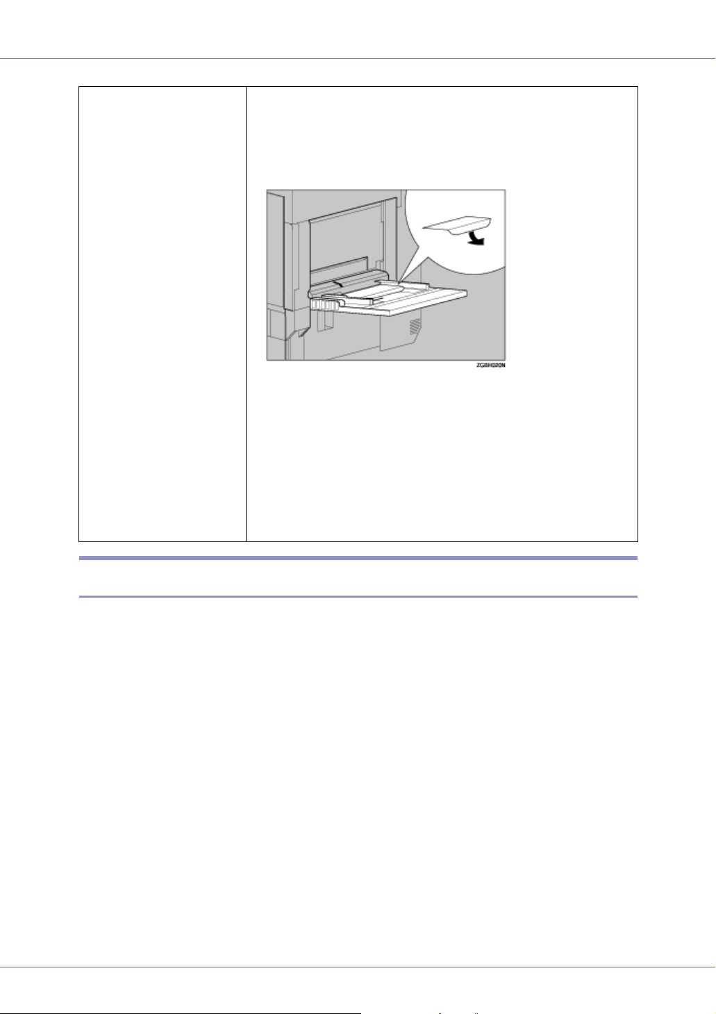
D If the external tray is attached to the printer, raise it in the direction of
the arrow ( ), and then remove it ( ).
58
Page 59

Replacing Consumables and Maintenance Kit
E Slowly pull out the left cover.
F Open the upper left cover.
G Holding the fusing unit handle as shown, slowly pull the fusing unit up,
and then put it down on a surface.
❒ Do not touch any area other than the green felt parts.
❒ Do not touch the inside of the fusing unit.
H Take the new fusing unit out of the bag and put it down on a level sur-
face.
59
Page 60

Replacing Consumables and Maintenance Kit
I Holding the fusing unit handle, slowly lower the unit to align it with the
marks on the machine stand.
❒ Install the fusing unit so the blue dial is on the front cover side.
J Slowly turn the fusing unit handle in the direction of the arrow, until it
clicks.
K Close the upper left cover ( ), and then push the part labeled “PUSH”
next to the handle at the bottom rear, until it clicks ( ).
60
Page 61

Replacing Consumables and Maintenance Kit
L If you removed the external tray in step
the hooks of the external tray into the printer slits, and lower it toward
you.
, reattach it to the printer. Insert
D
M If the duplex unit is installed, close the duplex reversal unit.
p.38 “Opening and Closing the Duplex Reversal Unit”
N If the 2 tray finisher or the booklet finisher is installed, reattach it to the
printer.
p.37 “Detaching the SR960 (2 Tray Finisher)”
p.38 “Detaching the SR950 (Booklet Finisher)”
O Plug in the power cable, and then turn on the power.
61
Page 62

Replacing Consumables and Maintenance Kit
Replacing the Dustproof Filter
The dustproof filter is attached to the black development unit. When replacing
the black development unit, also replace the dustproof filter.
The dustproof filter is attached to the left side of the printer, as shown.
A Turn off the power, and then unplug the power cable.
B Push in the grips on both sides of the dustproof filter cover to pull it off.
❒ Be sure to put the removed dustproof filter cover down on a stable and level
surface.
62
Page 63

Replacing Consumables and Maintenance Kit
C From the box that contained the black development unit, take out the
new dustproof filter and glove.
D Put the glove on either hand.
E Using your gloved hand, slowly take out the dustproof filters attached
to the dustproof filter cover, one by one, and put them into the box that
contained the black development unit.
❒ Handle the removed dustproof filters with care. If you shake them, dust
might scatter.
F Take off the glove.
63
Page 64

Replacing Consumables and Maintenance Kit
❒ Be sure to take off the glove before attaching a new dustproof filter.
G Attach the new dustproof filters to the dustproof filter cover one by one.
Attach the large filter.
H Attach the small filter.
I Insert the dustproof filter cover into the upper left area of the printer.
J Plug in the power cable, and then turn on the power.
64
Page 65

Replacing Consumables and Maintenance Kit
Replacing the Waste Toner Bottle
If “Replace Waste Toner (Type E)” appears on the display, replace the waste
toner bottle.
Replace Waste
Toner (Type E)
A Turn off the power, and then unplug the power cable.
B Take the new waste toner bottle out of the bag.
C Slowly open the front cover by pulling down from the two areas on the
left and right.
65
Page 66

Replacing Consumables and Maintenance Kit
D Slowly remove the used waste toner bottle from inside the printer.
❒ Be sure to remove the waste toner bottle horizontally.
E Remove the lid ( ), and then put it in the position shown in the illustra-
tion ( ).
F Put the used waste toner bottle into the bag that contained the new
waste toner bottle, and then seal the bag.
❒ Be sure to handle the bottle carefully so waste toner does not spill.
G Insert the new waste toner bottle as shown.
66
Page 67

Replacing Consumables and Maintenance Kit
H Push it in until it stops.
❒ Be sure to firmly insert the waste toner bottle to avoid toner leakage inside
the printer.
I Slowly close the front cover by pushing the two areas on the left and
right.
J Plug in the power cable, and then turn on the power.
67
Page 68

Replacing Consumables and Maintenance Kit
Replacing the Paper Feed Roller
If “Replace Feed Roller (Type H)” appears on the display, replace all three paper
feed rollers.
Replace Feed
Roller (Type H)
❒ The following illustrations are examples of replacing the paper feed rollers of
Tray 1. The same procedure applies to other trays.
A Check the contents of the box for the following items:
❖ Paper Feed Roller A
❖ Paper Feed Roller B
❖ Paper Feed Roller C
❖ Two Stoppers
B Turn off the power, and then unplug the power cable.
❒ If you are replacing the paper feed rollers of the optional 2000-sheet Large
Capacity Tray, remove all paper from the tray.
68
Page 69

Replacing Consumables and Maintenance Kit
C Slowly pull out all trays while lifting up a little.
❒ If you are replacing the paper feed rollers of the optional paper feed unit,
or 2000-sheet Large Capacity Tray, pull out all paper trays from each unit.
D Check the position of the paper feed rollers.
Confirm the positions and names of each roller.
69
Page 70

Replacing Consumables and Maintenance Kit
E While pushing the pin of the paper feed roller A outwards ( ), remove
the paper feed roller ( ).
F Remove the stopper from the paper feed roller B ( ), and then remove
the roller ( ).
G Remove the stopper from the paper feed roller C ( ), and then remove
the roller ( ).
70
Page 71

Replacing Consumables and Maintenance Kit
H Hold the new paper feed roller C with its gear towards the shaft. Insert it
into the rear shaft so that the roller gear interlocks with the shaft gear
( ). Lock the roller with the stopper ( ).
I Hold the new paper feed roller B with its gear towards the shaft. Insert it
into the rear shaft so that the roller gear interlocks with the shaft gear
( ). Lock the roller with the stopper ( ).
J Hold the new paper feed roller A with its pin towards you ( ). Insert the
roller onto the front shaft until it clicks into place ( ).
K Slowly slide all trays back into the printer until they stop.
❒ If you are replacing the paper feed rollers of the optional 2000-sheet Large
Capacity Tray, load the stocks removed in step
into the tray.
B
71
Page 72

Cleaning
Cautions to Take When Cleaning
• Do not remove any covers or screws other than those specified in this
manual. Some parts of the machine are at a high voltage and could
give you an electric shock. Also, if the machine has laser systems, direct (or indirect) reflected eye contact with the laser beam may cause
serious eye damage. When the machine needs to be checked, adjusted, or repaired, contact your service representative.
• Do not take apart or attempt any modifications to this machine. There
is a risk of fire, electric shock, explosion or loss of sight. If the machine has laser systems, there is a risk of serious eye damage.
• When removing misfed paper, do not touch the fusing section because it
could be very hot.
Clean the printer periodically to maintain print clarity.
Dry wipe the exterior using a soft cloth. If dry wiping is not enough, wipe using a
soft, wet cloth that is well wrung out. If you still cannot remove the stain or grime,
use a neutral detergent, then wipe over with a well wrung wet cloth, dry wipe, and
let it dry.
❒ To avoid deformation, discoloration, or cracking, do not use volatile chemi-
cals, such as benzine and thinner, or spray insecticide on the printer.
❒ If there is dust or grime inside the printer, wipe it away using a clean, dry cloth.
G1307528_1.00 Copyright © 2005 72
Page 73

Cleaning
Cleaning the Registration Roller
• The inside of the printer becomes very hot. To avoid burns, do not touch
parts labelled “hot surface”, otherwise it could cause a burn.
Clean the roller when replacing the black development unit.
A Turn off the power, and then unplug the power cable.
B Open the right cover as shown.
The registration roller is set as shown.
C Wipe around the registration roller by turning it and applying a soft
damp cloth.
73
Page 74

Cleaning
❒ Do not use chemical cleaners or organic solvents such as thinners or ben-
zene.
D Close the right cover by pushing the area labeled “PUSH”.
E Plug in the power cable, and then turn on the power.
74
Page 75

Cleaning
Cleaning the DustProof Glass
The dustproof glass may require cleaning if white lines appear on print.
A Turn off the power, and then unplug the power cable.
B Open the front cover, and then remove the cleaning brush.
There are four holes for cleaning the dustproof glass.
C Slide the cleaning brush in and out slowly 8 to 10 times to clean all four
areas.
❒ Do not insert the brush roughly. Doing so may damage the printer.
75
Page 76

Cleaning
D Return the cleaning brush to its original position.
E Plug in the power cable, and then turn on the power.
76
Page 77

Cleaning
Checking the Earth Leakage Breaker
This printer has an earth leakage breaker to prevent electric shock. Normally, the
earth leakage breaker will be at the “-” position.
Check the earth leakage breaker at least once a year using the following procedure.
• If the earth leakage breaker has tripped, contact your sales or service rep-
resentative. Do not reset earth leakage breaker yourself as you may get an
electric shock, the printer may catch fire, or the building earth leakage
breaker may trip.
❒ If the earth leakage breaker fails to trip when tested, contact your sales or ser-
vice representative.
A Make sure the printer’s ground is properly connected.
B Turn off the power.
If the 2 tray finisher or the booklet finisher is attached to the printer, detach it
before checking the earth leakage breaker.
C Press the earth leakage breaker's test button with a point of an object
such as a ballpoint.
77
Page 78

Cleaning
D Make sure the earth leakage breaker trips.
E Reset the earth leakage breaker by moving it to the “-“ position.
F Turn on the power.
❒ If the printer does not start up when the main power is switched on, check
whether the earth leakage breaker has tripped. If it has, contact your sales
or service representative. Do not reset the earth leakage breaker yourself.
78
Page 79

Adjusting the Printer
Adjusting the Color Registration
After moving the printer, printing on thick paper, or printing repeatedly for some
time, color degradation may occur. By performing color registration adjustment,
you can restore optimum print quality.
Auto Adjust
If documents show color degradation after the printer is moved, perform automatic color adjustment.
A Press the {Menu} key.
The [Menu] screen appears on the display.
B Press the {U} or {T} key to display “Maintenance”, and then press the
{# Enter} key.
Menu:
Maintenance
The maintenance menu appears.
C Press the {U} or {T} key to display “Color Regist.”, and then press the
{# Enter} key.
D Check “Auto Adjust” appears, and then press the {# Enter} key.
E Check “Now” appears, and then press the {# Enter} key.
The check message appears.
Press #
to adjust
F Press the {# Enter} key.
G1307528_1.00 Copyright © 2005 79
Page 80

Adjusting the Printer
Automatic color adjustment begins, and the following message appears.
Adjusting...
❒ To avoid malfunction, do not turn off the power while “Adjusting...” appears
on the display.
Automatic color adjustment takes about 50 seconds. A confirmation message
appears when complete.
Completed
Return to the color adjustment menu.
G When you have made all settings, press the {Online} key.
The initial screen appears.
Adjusting the Fuser for Thick Paper
If color registration shifts when using thick paper
If color registration shifts when using thick paper, adjust the fuser for thick paper.
❒ Fuser adjustment for thick paper is not possible if the toner has almost run out.
Carry out this adjustment after changing the toner cartridge.
❒ Thick paper is needed to make the adjustment. Use the thick paper you nor-
mally use.
A Load thick paper larger than A4 K in the bypass tray.
❒ For details about paper sizes the bypass tray can handle and paper loading
procedure, see p.6 “
Paper and Other Media Supported by This Printer”.
80
Page 81

Adjusting the Printer
B Press the {Menu} key.
The [Menu] screen appears on the display.
C Press the {U} or {T} key to display “Maintenance”, and then press the
{# Enter} key.
Menu:
Maintenance
The maintenance menu appears.
D Press the {U} or {T} key to display “Color Regist.”, and then press the
{# Enter} key.
E Press the {U} or {T} key to display “Fuser Adjust”, and then press the
{# Enter} key.
F Check “Thick Paper” appears, and then press the {# Enter} key.
Fuser Adjust:
Thick Paper
❒ If the toner cartridge is almost empty, the following message appears on
the display: (After changing the toner cartridge, carry out fuser adjustment
for thick paper. For details about changing the toner cartridge, see p.40
“Replacing the Toner Cartridge”.)
Failed.
Press # to exit
G Check the following message appears, and then press the {# Enter} key.
Press #
to adjust
81
Page 82

Adjusting the Printer
H Press the {# Enter} key.
Adjusting...
I When automatic color adjustment is complete, the confirmation mes-
sage about printing a test sheet appears. Wait for the following message
to appear, and then click the {# Enter} key.
Press # for Test
Print (Bypass)
J The following message appears:
Set Sheet, then#
A4 (297 x 210)
Make sure the paper size set in step
key.
The Fuser Adjust Sheet is printed. For test sheet samples, see p.83 “
Sheet Samples”.
❒ In this example, thick A4 paper is loaded in the bypass tray.
appears, and then press the {# Enter}
H
Test
K Compare the color adjustment sheet sample with the framed white part
of the printed pattern. If sample and printed pattern are almost the same,
select “0”. Otherwise, select one of the following values according to
the position of the color in the sample:
Color at center: 0
Color shifted to left: -1
Color shifted to right: +1
Select Action:
0: Exit
Select Action:
-1: Re-adjust
Select Action:
+1: Re-adjust
When you select “ 0 ”, the printer returns to the previous menu.
82
Page 83

Adjusting the Printer
If you select “-1” or “+1”, the printer returns to stepI. Keep adjusting until you
can select “ 0 ”.
L Press the {Online} key.
The initial screen appears.
Test Sheet Samples
The following illustration is an example of a test sheet printed during fuser adjustment for thick paper
❖ Fuser Adjust Sheet
83
Page 84

Adjusting the Printer
Correcting the Color Gradation
Color gradation during color printing various slightly depending on a number of
factors. If you print the same file repeatedly or toner was recently replaced,
changes may occur in color tones. When this happens, to obtain suitable print
results, color gradation can be corrected, although it is not usually necessary to
make any particular settings.
❒ If suitable results cannot be obtained after a single operation, repeat the cor-
rection several times, as needed.
❒ Corrections to color gradation will be applied to all user jobs.
❒ Use the same paper when printing a run of gradation corrections. If a different
type of paper is used, corrections may not be apparent.
❒ This requires the use of the supplied Color Calibration Sample Sheet.
❒ Corrections to color gradation are performed in the following order.
Set the Gradation Correction Value
During printing, you can correct the gradation in two areas: the bright part (highlighted) and the medium part (middle). The correction value for the highlighted
and the middle parts are set using “Calibr.1” and “Calibr.2” respectively.
84
Page 85

Adjusting the Printer
A Press the {Menu} key.
The [Menu] screen appears on the display.
B Press the {U} or {T} key to display “Maintenance”, and then press the
{# Enter} key.
Menu:
Maintenance
The maintenance menu appears.
C Press the {U} or {T} key to display “Color Calibrate”, and then press the
{# Enter} key.
❒ If you want to perform only calibration 2, proceed to step O.
D Check “Adj.Auto Dens.” is displayed, and then press the {# Enter} key.
E Check “Now” is displayed, and then press the {# Enter} key.
The check message appears.
Press #
to adjust
F Press the {# Enter} key.
Automatic density adjustment begins, and the following message appears.
Adjusting...
❒ To avoid malfunction, do not turn off the power while “Adjusting...” appears
on the display.
85
Page 86

Adjusting the Printer
A confirmation message appears when complete.
Completed
Return to the color calibrate menu.
G Press the {U} or {T} key to display “Start Calibr. 1”, and then press the
{# Enter} key.
H Check “Yes” is displayed, and then press the {# Enter} key to print gra-
dation correction sheet 1.
I Set the gradation correction value of the highlighted part using correc-
tion 1. For setting K (black) gradation, hold the correction value (0-6) for
“K” of the correction value setting sheet 1 over the color sample (K) for
gradation correction 1 of the Color Calibration Sample Sheet, and set
the numerical value of the closest color using either the {U} or {T} key.
Set the correction value using the supplied Color Calibration Sample Sheet
and the gradation correction sheet 1 printed in the previous step.
Set M (magenta), C (cyan), and Y (yellow) using the same method.
Calibrate 1:
K:3 M:3 C/Y:3/3
❒ Each time the {U} or {T} key is pressed, the value increases or decreases
respectively, in increments of 1.
❒ The correction value can be set between 0 and 6.
J Press the {# Enter} key after setting the K (black) gradation. The cursor
shifts to M (magenta).
Calibrate 1:
K:2 M:3 C/Y:3/3
K Set the gradation correction values for M (magenta), C (cyan), and Y (yel-
low) using the same procedure as for the K (black).
L If you finished all settings, ensure that the cursor is on the correction
value for Y (yellow), and then press the {# Enter} key.
Calibrate 1:
K:2 M:2 C/Y:2/2
The example shows the display of the control panel when the correction value
for each color is changed to 2.
86
Page 87

Adjusting the Printer
M Check “Yes” is displayed, and press the {# Enter} key to print the correc-
tion result.
N Check gradation correction sheet 1. To save the correction values,
check “Save and exit”is displayed and press the {# Enter} key. If you do
not want to save the correction values after this procedure, press the
{U} or {T} key to display “Exit don't save”, and then press the {# Enter}
key.
❒ If you complete this procedure without saving the correction values, the
changes will not be applied to subsequent print jobs.
Calibrate 1:
Save and exit
Calibrate 1:
Exit don't save
This concludes the setting for correction 1. Next, proceed to correction 2.
O Press the {T} key to display “Start Calibr. 2”, and then press the {# Enter}
key.
Color Calibrate:
Start Calibr. 2
P Check “Yes” is displayed, and then press the {# Enter} key to print gra-
dation correction sheet 2.
Print Sheet 2?:
Yes
Q Perform the same operations as in step
tion value of the middle part using calibration 2.
and set the gradation correc-
I
R After completing all settings, press the {Online} key.
The initial screen appears.
❒ Displays on the screen are just examples.
87
Page 88

Adjusting the Printer
Viewing the Color Calibration Sample Sheet and Gradation
Correction Sheet
The color gradation correction value setting sheet contains two color sample columns: the “Sample 1” column for setting the highlight part and the “Sample 2”
column for setting the middle part.
Similarly, there are two gradation correction sheets: “Gradation correction sheet
1” for setting the highlight part and “Gradation correction sheet 2” for setting the
middle part. Gradation correction sheet 1 is used for calibration 1, while Gradation correction sheet 2 is used for calibration 2.
❖ Color sample and correction values
The following explains how to use the color sample of the Color Calibration
Sample Sheet and the correction values of the gradation correction sheet.
This explanation uses K (black) as an example. The setting method for M (magenta) is similar. For C/Y (cyan/yellow), the correction value is determined
based on combinations of these two colors, although settings are made for
each color.
❒ Compare the K correction value (0-6) of gradation correction sheet 1 with
the K color sample of the Color Calibration Sample Sheet. Determine the
color that matches the color sample the closest, and then set the correction
value of that color using the control panel. The currently set correction value is printed in red.
88
Page 89

Adjusting the Printer
❖ Relationship between the gradation correction sheets and the display
The printed gradation correction sheet and display correspond as shown in
the following diagram. The gradation correction sheets are used to determine
the correction values for the colors K (black), M (magenta), C (cyan), and Y
(yellow). These values are set using the control panel.
❒ XXXX represents the printer model name.
A K (black) correction values
Use to adjust the color printed when only black toner is used. The currently
set correction value is printed in red.
B M (magenta) correction values
Use to adjust the color printed when only magenta toner is used. The currently set correction value is printed in red.
C C (cyan)/Y (yellow) correction values
Use to adjust the color printed when cyan and yellow toner are used. For
C/Y (cyan/yellow), the correction values are determined based on a combination of these two colors, although settings are made separately for
each color.
D K, M, C/Y
The numerical values set at time of gradation correction sheet printing are
shown. These correspond to the numerical values set using the control
panel.
Resetting the gradation correction values to the initial values
Reset the correction value default.
89
Page 90

Adjusting the Printer
A Press the {Menu} key.
The [Menu] screen appears on the display.
B Press the {U} or {T} key to display “Maintenance”, and then press the
{# Enter} key.
Menu:
Maintenance
The maintenance menu appears.
C Press the {U} or {T} key to display “Color Calibrate”, and then press the
{# Enter} key.
D Press the {U} or {T} key to display “Reset”, and then press the {# Enter}
key.
Color Calibrate:
Reset
A confirmation message appears.
Press # to reset
calibration
E Press the {# Enter} key.
A message indicating the gradation correction values have returned to their
default appears.
Calibration was
reset
After about 2 seconds, the display returns to the “Color Calibrate: Reset”
menu.
F Press the {Online} key.
90
Page 91

Adjusting the Printer
The initial screen appears.
91
Page 92

Adjusting the Printer
Adjusting Image Density
Adjust image density when print becomes hazy gray or the image looks patchy.
❒ Extreme settings may cause output to appear dirty.
❒ Image density settings should be made from the application or the printer driv-
er, whenever possible.
❒ Changing image density settings might cause deterioration in color balance.
We recommend leaving image density at the factory default setting.
A Press the {Menu} key.
The [Menu] screen appears on the display.
B Press the {U} or {T} key to display “Maintenance”, and then press the
{# Enter} key.
Menu:
Maintenance
The maintenance menu appears.
C Press the {U} or {T} key to display “Image Density”, and then press the
{# Enter} key.
D Press the {U} or {T} key to select the color you want to adjust, and then
press the {# Enter} key.
Image Density:
Black
92
Page 93

Adjusting the Printer
E Press the {U} or {T} key to set the image density value, and then press
the {# Enter} key.
Black:
(-3 +3) 0
❒ You can adjust image density in seven increments, from -3 to +3. Increas-
ing the value makes printout darker; decreasing the value makes printout
lighter.
To adjust another color, repeat steps
and E.
D
F Press the {Online} key.
The initial screen appears.
93
Page 94

Adjusting the Printer
Adjusting Tray Registration
You can adjust the registration of each tray. The vertical adjustment is used for
all trays. Normally, you need not update the registration. But when the optional
paper feed unit or the duplex unit is installed, updating is useful in some cases.
The following procedure describes how to adjust tray 3. The same procedure applies to other trays as well.
A Press the {Menu} key.
The [Menu] screen appears on the display.
B Press the {U} or {T} key to display “Maintenance”, and then press the
{# Enter} key.
Menu:
Maintenance
The maintenance menu appears.
C Press the {U} or {T} key to display “Registration”, and then press the
{# Enter} key.
The registration menu appears.
D Print the test sheet to preview the settings. Confirm that “Prt. Test
Sheet” is displayed, and then press the {# Enter} key.
A screen prompting you to select the tray to be adjusted appears.
E Press the {U} or {T} key to select the tray to adjust, and then press the
{# Enter} key.
Prt. Test Sheet:
Tray 2
The test sheet prints out. The display returns to the registration menu. Press
the {Escape} key.
94
Page 95

Adjusting the Printer
F Confirm the position of the image on the test sheet, and then adjust the
registration value.
In this setting, adjust the margins of the test sheet so that they are equal in
size.
G Press the {Escape} key.
H Press the {U} or {T} key to display “Adjustment”, and then press the {#
Enter} key.
I Press the {U} or {T} key to display the parameter to be adjusted, and
then press the {# Enter} key.
Adjustment:
Horiz: Tray 2
J Press the {U} or {T} key to set the registration value (mm).
Horiz: Tray 2
(-5.0 +5.0) 0.0
95
Page 96

Adjusting the Printer
Increase the value to shift the print area in the positive direction, and decrease
to shift in the negative direction.
A : Print Area
B : Feed Direction
❒ Pressing the {U} or {T} key makes the value increase or decrease by 1.0
mm steps.
K Press the {# Enter} key.
The display returns to the print area “Adjustment” menu.
Registration:
Adjustment
L Print the test sheet to confirm the adjustment result.
M Press the {Online} key.
The initial screen appears.
96
Page 97

Troubleshooting
Error & Status Messages on the Control
Panel
This section explains what the messages that appear on the control panel mean
and what to do when a particular message appears.
❖ Messages (in alphabetical order)
Messages
/ Second messages
Add staples The stapler is out of staples.
Job is not stapled.
Add Toner
XXX/XXX
Add Toner:
Cyan
Add Toner:
Magenta
Add Toner:
Yellow
Calibrating... The printer is calibrating the
Call Service: EC
Power Off On
/ If Error Reoccur
Call Service
The printer is out of the indicated toner(s).
XXX: Yellow/Magenta/Cyan/Black
The printer is out of toner (C). Replace the toner cartridge (C).
The printer is out of toner (M). Replace the toner cartridge (M).
The printer is out of toner (Y). Replace the toner cartridge (Y).
color.
A communication error sent
from the engine to the controller.
Description Solution
Replace staples.
See p.128 “
Replace the toner cartridge of the indicated color(s).
See p.40 “
tridge”.
See p.40 “
tridge”.
See p.40 “
tridge””.
See p.40 “
tridge”.
Wait a while.
A communication error sent from the
engine to the controller.
Adding Staples”.
Replacing the Toner Car-
Replacing the Toner Car-
Replacing the Toner Car-
Replacing the Toner Car-
Cannot check
Signal in Ad hoc
Certificate auto
renewal failed
G1307528_1.00 Copyright © 2005 97
An attempt to check the radio
signal was made while the
communication mode was set
to [Ad hoc] in the interface settings.
Renewal of the certificate automatically has failed.
To check the radio signal , select Infrastructure in the communication
mode settings.
Turn the power off, and then on. If the
message appears again, contact your
sales or service representative.
Page 98

Troubleshooting
Messages
/ Second messages
Change Setting
Tray #
/ Paper Size:
Paper Type:
Check Toner Crtg
XXX/XXX
Close
Front Cover
Close
Right Cover
Close Duplex
Unit Cover
Close Finisher
Front Cover
Description Solution
The paper size and type setting
in the tray differs from that of
actual paper size and type in
the tray.
#: tray number
The indicated toner cartridge is
not set correctly.
XXX: Yellow/Magenta/Cyan/Black
The front cover is open. Close the front cover for the printer.
The right cover is open. Close the right cover.
The cover for the duplex unit is
open.
The front cover for the finisher
is open.
Load paper of the selected size in the
tray, and then change the paper size
setting with the control panel. Or,
press the {Form Feed} key, and then
select the tray using the control panel.
Or, press the {Job Reset} key to cancel
the print job.
Set the indicated toner cartridge(s)
correctly.
See p.40 “
tridge”.
Close the cover for the duplex unit.
Close the front cover for the finisher.
Replacing the Toner Car-
Close Finisher
Upper Cover
Close Lower
Right Cover
Close Upper Left
Cover
Close Upper Right
Cover
DHCP assigned
Cannot change
The finisher upper cover is
open.
The paper entrance cover for
the finisher is open.
The right cover for the paper
feed table/Large Capacity Tray
is open.
The upper left cover (the cover
for the fusing unit) is open.
The upper right cover (the cover for the toner cartridge) is
open.
An attempt to change the IP address, subnet mask or gateway
address was made while DHCP
was set to [On].
Close the upper cover for the finisher.
Close the upper entrance cover for the
finisher.
Close the right cover for the paper
feed table/Large Capacity Tray.
Close the upper left cover.
Close the upper right cover.
Make the change after setting DHCP
to [Off].
98
Page 99

Troubleshooting
Messages
/ Second messages
Empty Punch Receptacle
Energy Save Mode In Energy Save Mode level 2. No action required.
Error: Enter 10
or 26 characters
Error: Enter 5
or 13 characters
Error: Tray #
Form Feed
/ Or Job Reset
Then Power OffOn
The Punch Chips container is
full of punch chips.
An ID with an invalid number of
digits was entered for the WEP
key.
An ID with an invalid number of
digits was entered for the WEP
key.
The printer identified the failure
of the indicated paper tray. The
job is not printed.
#: tray number
Description Solution
Empty the punch waste box.
See p.134 “
Chips”.
If the message appears the punch
waste box is not full, remove the
Punch-hole chips on the top of the
punch waste box.
See p.134 “
Chips”.
Enter the correct number of digits for
the WEP key.
Enter the correct number of digits for
the WEP key.
Apply Form Feed from another tray or
cancel the job, and then switch your
printer Off, then back On. If the error
continues, contact your sales or service representative.
Removing Punch-hole
Removing Punch-hole
Exceeded Max.
Pages (Collate)
Exceeded Max.
Stored Files
Exceeded Max.
Stored Pages
Hardware Problem
Ethernet
Hardware Problem
Finisher
The printer identified a collation
page overflow error.
The maximum number of
stored files has been exceeded
during Sample Print of Locked
Print.
The maximum number of pages has been exceeded during
Sample Print of Locked Print.
The printer identified an Ethernet error.
There is a problem with the finisher.
Add extra RAM.
Install the optional hard disk drive.
Delete stored files.
Reduce the number of pages to print.
Turn the power off, and then on. If the
message appears again, contact your
sales or service representative.
Turn the power off, and then on. Remove and re-install the finisher correctly. If the message appears again,
contact your sales or service representative.
See p.37 “
the Options”.
Detaching and Reattaching
99
Page 100

Troubleshooting
Messages
/ Second messages
Hardware Problem
HDD
Hardware Problem
IEEE1394
Description Solution
The printer identified a HDD
Board error.
The printer identified an IEEE
1394 interface board error.
Turn the power off, and then on. Remove and re-install the HDD board
correctly. If the message appears
again, contact your sales or service
representative.
See “Attaching Printer Hard Disk Type
7100”, Setup Guide.
Turn the power off, and then on.
Remove and re-install the IEEE 1394
interface board correctly.
A Check the IEEE 1394 interface
board is correctly attached to the
computer.
B Check the IEEE 1394 interface ca-
ble is securely connected.
C Unplug the IEEE 1394 interface
cable which is connected to the
printer.
D Restart the computer. If the mes-
sage appears even after executing
above operation, proceed to the
following steps.
E Execute the utility tool for IEEE
1394 interface board that is stored
in the following path in the CDROM labeled “Printer Drivers and
Utilities”: UTILITY\1394
Hardware Problem
Option RAM
The printer identified an optional RAM error.
❒ For details about using the utility
tool for IEEE 1394, see the README file in the same directory in
the CD-ROM. If the message appears again, contact your sales or
service representative.
See “Attaching IEEE 1394 Interface
Board Type B”, Setup Guide.
Turn the power off, and then on. Remove and re-install the optional RAM.
If the message appears again, contact
your sales or service representative.
See “Attaching Memory Unit Type C
(SDRAM Module)”, Setup Guide.
100
 Loading...