

Page 1

®
®
®
RICOH GROUP COMPANIES
G080/G367
PARTS CATALOG
001581MIU
Page 2

Page 3

®
®
PARTS CATALOG
G080/G367
RICOH GROUP COMPANIES
Page 4

Page 5

G080/G367
PARTS CATALOG
001581MIU
Page 6

Page 7

r
r
It is the reader's responsibility when discussing the information contained within this
document to maintain a level of confidentiality that is in the best interest of Ricoh
Corporation and its member companies.
NO PART OF THIS DOCUMENT MAY BE REPRODUCED IN ANY
FASHION AND DISTRIBUTED WITHOUT THE PRIOR
PERMISSION OF RICOH CORPORATION.
All product names, domain names or product illustrations, including desktop images,
used in this document are trademarks, registered trademarks or the property of thei
respective companies.
They are used throughout this book in an informational or editorial fashion only and fo
the benefit of such companies. No such use, or the use of any trade name, or web
site is intended to convey endorsement or other affiliation with Ricoh products.
2003 RICOH Corporation. All rights reserved.
Page 8

Page 9

LEGEND
PRODUCT CODE COMPANY
G080 DSc38U LP138C Aficio CL7000 CLP28
GESTETNER LANIER RICOH SAVIN
G367 DSc38US LP138CMF Aficio
CL7000CMF
G348 Duplex Unit Type 7000
G567 Paper Feed Unit Type 3800C(1 Tray)
G568 Paper Feed Unit Type 3800C(2 Trays)
G569 Paper Bank PS470
G565 Finisher SR770
B337 Punch Kit Unit Type 1045
G367 Copier Feature Expander Type 7000
G306 Multi-Bin Unit PT460
G329 Planten Cover Type 3800C
G564 Auto Reverse Document Feeder DF73
G307/G324/G325 Fax Option/G3 Interface Unit Type 3800/ISDN Option Type 3800C
CLP28S
DOCUMENTATION HISTORY
REV. NO. DATE COMMENTS
*
3/2003 Original Printing
Page 10

Page 11

G080/G367 PARTS CATALOG
TABLE OF CONTENTS
B080 PARTS LOCATION AND LIST
LOCATION OF UNIT ............................................... 2
1.EXTERIOR 1 (G080) ........................................... 8
2.EXTERIOR 2 (G080) .......................................... 10
3.LASER UNIT (G080) .......................................... 12
4.1ST CASSETTE (G080)..................................... 14
5.2ND CASSETTE (G080) .................................... 16
6.1ST PAPER FEED SECTION (G080)................ 18
7.2ND PAPER FEED SECTION (G080) ............... 20
8.VERTICAL TRANSPORT SECTION (G080) ..... 22
9.MANUAL PAPER FEED 1 (G080)...................... 24
10.MANUAL PAPER FEED 2 (G080) .................... 26
11.PAPER REGISTRATION (G080) ...................... 28
12.COLOR TONER HOPPER (G080).................... 30
13.BLACK TONER HOPPER (G080)..................... 32
14.PCU/DEVELOPMENT UNIT (G080) ................. 34
15.TRANSFER UNIT 1 (G080)............................... 36
16.TRANSFER UNIT 2 (G080)............................... 38
17.TRANSFER UNIT 3 (G080)............................... 40
18.TRANSFER UNIT 4 (G080)............................... 42
19.FUSING UNIT 1 (G080) .................................... 44
20.FUSING UNIT 2 (G080) .................................... 46
21.PAPER EXIT SECTION 1 (G080) ..................... 48
22.PAPER EXIT SECTION 2 (G080) ..................... 50
23.PAPER EXIT SECTION 3 (G080)...................... 52
24.PAPER EXIT SECTION 4 (G080)...................... 54
25.PAPER EXIT SECTION 5 (G080)...................... 56
26.WASTE TONER TRANSFER SECTION (G080) 58
27.DRIVE SECTION 1 (G080) ................................ 60
28.DRIVE SECTION 2 (G080) ................................ 62
29.DRIVE SECTION 3 (G080) ................................ 64
30.DRIVE SECTION 4 (G080) ................................ 66
31.ELECTRICAL SECTION 1 (G080)..................... 68
32.ELECTRICAL SECTION 2 (G080)..................... 70
33.FRAME SECTION 1 (G080) .............................. 72
34.FRAME SECTION 2 (G080) .............................. 74
35.FRAME SECTION 3 (G080) .............................. 76
36.PRINTER CONTROL BOARD (G080)............... 78
37.BCU BOARD (G080).......................................... 88
38.DECALS AND DOCUMENTS (G080)...............100
39.SPECIAL TOOLS (G080)..................................102
B080 PARTS INDEX
PARTS INDEX .......................................................... 2
DUPLEX UNIT TYPE 7000 G348 PARTS LOCATION
AND LIST
1.DUPLEX UNIT 1 (G348) ...................................... 2
Page 12

2.DUPLEX UNIT 2 (G348) ...................................... 4
3.DUPLEX UNIT 3 (G348) ...................................... 6
4.DUPLEX UNIT 4 (G348) ...................................... 8
5.DUPLEX UNIT 5 (G348) ..................................... 10
6.DECALS AND DOCUMENTS (G348)................. 12
DUPLEX UNIT TYPE 7000 G348 PARTS INDEX
PARTS INDEX .......................................................... 2
PAPER FEED UNIT TYPE 3800C (1 TRAY) G567
PARTS LOCATION AND LIST
1.EXTERIOR (G567)............................................... 2
2.PAPER CASSETTE (G567)................................. 4
3.PAPER FEED SECTION (G567) ......................... 6
4.DRIVE AND ELECTRICAL (G567) ...................... 8
5.INTERFACE BOARD (G567).............................. 10
6.DECALS AND DOCUMENTS (G567)................. 12
PAPER FEED UNIT TYPE 3800C (1 TRAY) G567
PARTS INDEX
PARTS INDEX .......................................................... 2
PAPER FEED UNIT TYPE 3800C (2TRAYS) G568
PARTS LOCATION AND LIST
1.EXTERIOR (G568)............................................... 2
2.PAPER CASSETTE (G568)................................. 4
3.PAPER FEED SECTION 1 (G568) ...................... 6
4.PAPER FEED SECTION 2 (G568) ...................... 8
5.DRIVE AND ELECTRICAL (G568) ..................... 10
6.INTERFACE BOARD (G568).............................. 12
7.DECALS AND DOCUMENTS (G568)................. 14
PAPER FEED UNIT TYPE 3800C (2TRAYS) G568
PARTS INDEX
PARTS INDEX .......................................................... 2
PAPER BANK PS470 G569 PARTS LOCATION AND
LIST
1.EXTERIOR (G569)............................................... 2
2.PAPER TRAY 1 (G569) ....................................... 4
3.PAPER TRAY 2 (G569) ....................................... 6
4.PAPER TRAY 3 (G569) ....................................... 8
5.PAPER FEED SECTION 1 (G569) ..................... 10
6.PAPER FEED SECTION 2 (G569) ..................... 12
7.DRIVE AND ELECTRICAL (G569) ..................... 14
8.INTERFACE BOARD (G569).............................. 16
9.DECALS AND DOCUMENTS (G569)................. 18
PAPER BANK PS470 G569 PARTS INDEX
PARTS INDEX .......................................................... 2
FINISHER SR770 G565 PARTS LOCATION AND
LIST
LOCATION OF UNIT ................................................ 2
1.EXTERIOR 1 (G565)............................................ 6
2.EXTERIOR 2 (G565)............................................ 8
3.PUNCH FRAME (G565)...................................... 10
4.PAPER TRANSFER 1 (G565) ............................ 12
5.PAPER TRANSFER 2 (G565) ............................ 14
6.PAPER TRANSFER 3 (G565) ............................ 16
7.STAPLE TRAY 1 (G565)..................................... 18
8.STAPLE TRAY 2 (G565)..................................... 20
Page 13

9.STAPLE UNIT 1 (G565) ..................................... 22
10.STAPLE UNIT 2 (G565) .................................... 24
11.UPPER PAPER EXIT 1 (G565) ......................... 26
12.UPPER PAPER EXIT 2 (G565) ......................... 28
13.UPPER PAPER EXIT 3 (G565) ......................... 30
14.UPPER PAPER EXIT 4 (G565) ......................... 32
15.UPPER PAPER EXIT 5 (G565) ......................... 34
16.LOWER PAPER EXIT 1 (G565) ........................ 36
17.LOWER PAPER EXIT 2 (G565) ........................ 38
18.SHIFT DRIVE 1 (G565) ..................................... 40
19.SHIFT DRIVE 2 (G565) ..................................... 42
20.DRIVE SECTION (G565)................................... 44
21.ELECTRICAL SECTION (G565) ....................... 46
22.MAIN CONTROL BOARD (G565) ..................... 48
23.DECAL AND DOCUMENT (G565) .................... 52
FINISHER SR770 G565 PARTS INDEX
PARTS INDEX.......................................................... 2
PUNCH KIT TYPE1045 B377 PARTS LOCATION
AND LIST
1.PUNCH KIT TYPE1045 (B377) ........................... 2
PUNCH KIT TYPE1045 B377 PARTS INDEX
PARTS INDEX.......................................................... 5
MAIL BIN TYPE 3800C PARTS LOCATION AND LIST
1.EXTERIOR (G566) .............................................. 2
2.PAPER EXIT SECTION 1 (G566) ....................... 4
3.PAPER EXIT SECTION 2 (G566) ....................... 6
4.PAPER EXIT SECTION 3 (G566) ....................... 8
5.DECALS AND DOCUMENTS (G566) ................ 10
MAIL BIN TYPE 3800C PARTS INDEX
PARTS INDEX.......................................................... 2
COPIER FEATURE EXPANDER TYPE 7000 G367
PARTS LOCATION AND LIST
1.SCANNER UNIT 1 (G367)................................... 2
2.SCANNER UNIT 2 (G367)................................... 4
3.SCANNER UNIT 3 (G367)................................... 6
4.SCANNER UNIT 4 (G367)................................... 8
5.SCANNER UNIT 5 (G367).................................. 10
6.IPU BOARD (G367)............................................ 12
COPIER FEATURE EXPANDER TYPE 7000 G367
PARTS INDEX
PARTS INDEX.......................................................... 2
MULTI-BIN UNIT PT460 G306 PARTS LOCATION
AND LIST
1.MULTI-BIN UNIT (G306) ..................................... 2
MULTI-BIN UNIT PT460 G306 PARTS INDEX
PARTS INDEX.......................................................... 2
PLATEN COVER TYPE 3800C PARTS LOCATION
AND LIST
1.PLATEN COVER (G329)..................................... 2
PLATEN COVER TYPE 3800C PARTS INDEX
PARTS INDEX.......................................................... 2
AUTO REVERSE DOCUMENT FEEDER DF73 G564
PARTS LOCATION AND LIST
1.EXTERIOR (G564) .............................................. 2
Page 14

2.PAPER FEED 1 (G564) ....................................... 4
3.PAPER FEED 2 (G564) ....................................... 6
4.PAPER FEED 3 (G564) ....................................... 8
5.TRANSPORT SECTION 1 (G564)...................... 10
6.TRANSPORT SECTION 2 (G564)...................... 12
7.DRIVE AND ELECTRICAL 1 (G564).................. 14
8.DRIVE AND ELECTRICAL 2 (G564).................. 16
9.FRAME SECTION (G564) .................................. 18
10.MAIN CONTROL BORAD (G564) ..................... 20
AUTO REVERSE DOCUMENT FEEDER DF73 G564
PARTS INDEX
PARTS INDEX.......................................................... 2
FAX OPTION/G3 INTERFACE UNIT TYPE 3800C/ISDN
OPTION TYPE 3800C G307/G324/G325 PARTS
LOCATION AND LIST
1.FAX UNIT (G307) ................................................ 2
2.G3/G4 UNIT (G324/G325) ................................... 4
3.FCU BOARD (G307)............................................ 6
4.NCU BOARD (G307/G324 NA) .......................... 12
5.NCU BOARD (G307/G324 EU) .......................... 14
FAX OPTION/G3 INTERFACE UNIT TYPE 3800C/ISDN
OPTION TYPE 3800C G307/G324/G325 PARTS INDEX
PARTS INDEX .......................................................... 2
Page 15

G080 PARTS LOCATION AND LIST
Page 16

Page 17

This section instructs you as to the numbers and names of parts on this machine.
Page 18
LOCATIONS OF UNITS LOCATIONS OF UNITS
LOCATIONS OF UNITS
LOCATIONS OF UNITS
LOCATIONS OF UNITS
1. Exterior 1 (G080)
4. 1st Cassette (G080)
See Page 9
2. Exterior 2 (G080)
See Page 11
5. 2nd Cassette (G080)
3. Laser Unit (G080)
See Page 13
6. 1st Paper Feed Section (G080)
See Page 15
G080 2 Parts Location and List
See Page 17
See Page 19
Page 19
LOCATIONS OF UNITS LOCATIONS OF UNITS
LOCATIONS OF UNITS
LOCATIONS OF UNITS
LOCATIONS OF UNITS
7. 2nd Paper Feed Section (G080)
See Page 21
10. Manual Paper Feed 2 (G080)
8. Vertical Transport Section (G080)
See Page 23
11. Paper Registration (G080)
9. Manual Paper Feed 1 (G080)
See Page 25
12. Color Toner Hopper (G080)
See Page 27
G080 3 Parts Location and List
See Page 29
See Page 31
Page 20
LOCATIONS OF UNITS LOCATIONS OF UNITS
LOCATIONS OF UNITS
LOCATIONS OF UNITS
LOCATIONS OF UNITS
13. Black Toner Hopper (G080)
See Page 33
16. Transfer Unit 2 (G080)
14. PCU/Development Unit (G080)
See Page 35
17. Transfer Unit 3 (G080)
15. Transfer Unit 1 (G080)
See Page 37
18. Transfer Unit 4 (G080)
See Page 39
G080 4 Parts Location and List
See Page 41
See Page 43
Page 21
LOCATIONS OF UNITS LOCATIONS OF UNITS
LOCATIONS OF UNITS
LOCATIONS OF UNITS
LOCATIONS OF UNITS
19. Fusing Unit 1 (G080)
See Page 45
22. Paper Exit Section 2 (G080)
20. Fusing Unit 2 (G080)
See Page 57
23. Paper Exit Section 3 (G080)
21. Paper Exit Section 1 (G080)
See Page 49
24. Paper Exit Section 4 (G080)
See Page 51
G080 5 Parts Location and List
See Page 53
See Page 55
Page 22
LOCATIONS OF UNITS LOCATIONS OF UNITS
LOCATIONS OF UNITS
LOCATIONS OF UNITS
LOCATIONS OF UNITS
25. Paper Exit Section 5 (G080)
See Page 57
28. Drive Section 2 (G080)
26. Waste Toner Transfer Section (G080)
See Page 59
29. Drive Section 3 (G080)
27. Drive Section 1 (G080)
See Page 61
30. Drive Section 4 (G080)
See Page 63
G080 6 Parts Location and List
See Page 65
See Page 67
Page 23
LOCATIONS OF UNITS LOCATIONS OF UNITS
LOCATIONS OF UNITS
LOCATIONS OF UNITS
LOCATIONS OF UNITS
31. Electrical Section 1 (G080)
See Page 69
34. Frame Section 2 (G080)
32. Electrical Section 2 (G080)
See Page 71
35. Frame Section 3 (G080)
33. Frame Section 1 (G080)
See Page 73
See Page 75
G080 7 Parts Location and List
See Page 77
Page 24
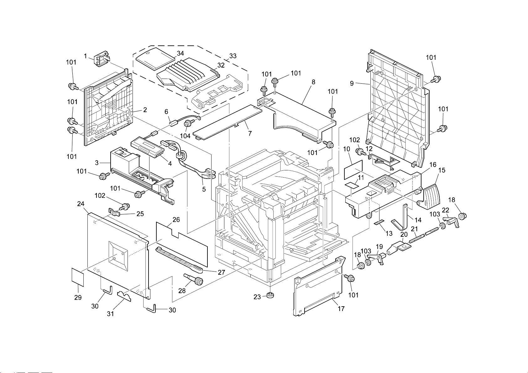
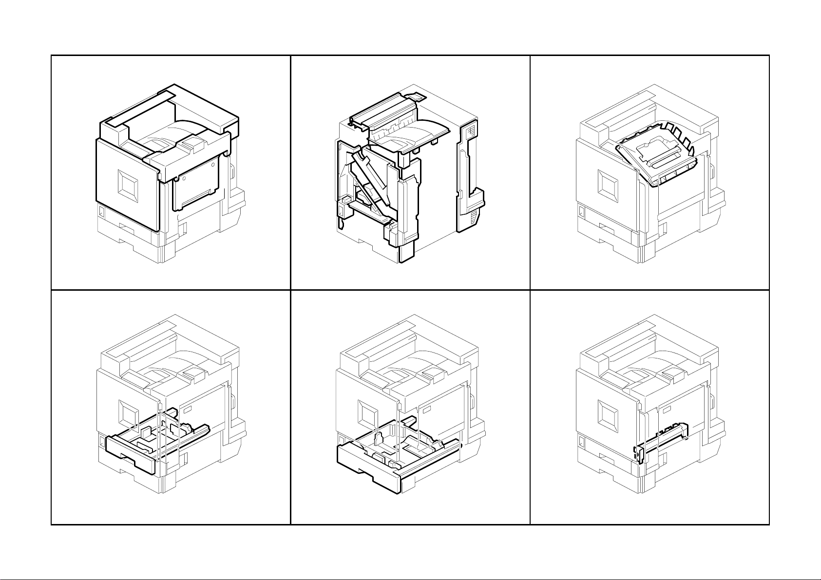
1.Exterior 1 (G080)
G080 8 Parts Location and List
Page 25

1.Exterior 1 (G080)
Index
Index
No.
No.
1 G060 1289 Small Cover - Option 1
2 G060 1220 Lower Left Cover 1
3 G080 1283 Inner Cover - Upper 1
4 G060 7011 Operation Panel - LT 1
4 G060 7111 Operation Panel - A4 1
5 G080 5484 Harness - Operation Sub-unit 1
6 G080 5515 Harness - Ground Wire - Operation Sub-unit 1
7 G060 1288 Large Cover - Option 1
8 G080 1272 Cover - Upper - Rear 1
9 G077 1268 Rear Cover 1
10 GA00 3009 Sheet - Toner Supply 1
11 GA00 3038 Decal - Inkjet Paper Caution 1
12 G080 1319 Electrode - Ground Plate 1
13 AA15 3462 Seal - C/Y 1
14 G080 1321 Band - Stopper - Cover - Right Upper 1
15 G060 1293 Exit End Fence 1
16 G080 1265 Cover - Right - Upper 1
17 G080 1224 Inner Cover - Manual Feed - Ass'y 1
18 AA08 2101 Bushing - 6x10x6 2
19 G060 1312 Front Stopper Pawl 1
20 G080 1320 Grip - Cover - Right Upper - Peen 1
21 G060 1314 Stopper Pawl Shaft 1
22 G060 1313 Rear Stopper Pawl 1
23 AH01 0009 Rubber Pad - H5 8
24 G077 1262 Cover - Front 1
25 B024 1264 Magnet Catch 1
26 G080 1292 Sheet -Operate -J-P2 1
27 G060 1995 Cleaner - Dust Proof Glass 1
28 G060 2989 Screw Driver 1
29 G080 7005 Decal - Emblem - EXP 1
29 G080 7505 Decal - Emblem (SVN) 1
29 G080 7506 Decal - Emblem (GES NA) 1
29 G080 7605 Decal - Emblem (NRG NAS) 1
29 G080 7606 Decal - Emblem (NRG REX) 1
29 G080 7607 Decal - Emblem (NRG GES) 1
Part No.
Part No.
Description
Description
Q’ty Per
Q’ty Per
Assembly
Assembly
Index
Index
No.
No.
29 G080 7705 Decal - Emblem (INF) 1
29 G080 7905 Decal - Emblem (LAN EU) 1
30 G020 1332 Hinge - Front Cover 2
31 GA00 3034 Decal - Energystar 1
32 G060 4491 Exit Tray 1
33 G060 4490 Exit Tray 1
34 G060 4492 Sub Exit Tray 1
101 0451 3008H Tapping Screw - M3x8
102 0450 3008B Tapping Screw - M3x8
103 0720 0040E Retaining Ring - M4
104 0451 3006B Tapping Screw - M3x6
Part No.
Part No.
Description
Description
Q’ty Per
Q’ty Per
Assembly
Assembly
G080 9 Parts Location and List
Page 26

2.Exterior 2 (G080)
G080 10 Parts Location and List
Page 27

2.Exterior 2 (G080)
Index
Index
No.
No.
1 GA01 2000 Upper Filter 1
2 GA01 2001 Lower Filter 1
3 G060 1300 Filter Case 1
4 G060 1269 Left Rear Cover 1
5 G060 1281 Louver - Left Rear Cover 1
6 G060 1271 Front Cover - Left Lower 1
7 G060 5813 Bracket - Main Switch 1
8 AA14 3219 Stepped Screw 1
9 G060 2450 Drum Stay - PCU - Ass'y 1
10 G060 1285 Lower Inner Cover 1
11 G060 2460 Screw - M4X6 2
12 GA00 3025 Decal - Drum Stay 1
13 G060 2455 Cover - Drum Stay 1
14 G060 2461 Nut - M7 2
15 G060 2457 Unit Detection Switch 1
16 G060 5489 Harness - Unit Detection Switch 1
17 G060 2456 Spring Plate- Unit Detection Switch 1
18 G060 2451 Drum Stay 1
19 AG07 1011 Magnet Catch 2
20 G080 1282 Inner Cover - Right 1
21 G080 1284 Inner Cover - Left 1
22 G060 2481 Left Spring - Drum Stay 1
23 G080 1295 Inner Cover - Left - Small 1
24 G060 2482 Right Spring - Drum Stay 1
25 G060 1266 Front Cover - Right Lower 1
26 G060 1287 Front Right Cover 1
27 G080 1267 Cover - Right - Rear 1
28 G060 2949 Magnetic Clutch Cover 1
29 G060 2950 Spring Plate - Clutch Cover 1
30 G060 1280 Supporting Plate - Right Rear Cover 1
31 G080 1294 Inner Cover - Toner Cartridge 1
32 G077 1275 Upper Cover - Exit Tray 1
33 G060 1279 Exit Cover 1
34 G060 1274 Upper Exit Cover 1
Part No.
Part No.
Description
Description
Q’ty Per
Q’ty Per
Assembly
Assembly
Index
Index
No.
No.
101 0451 3008H Tapping Screw - M3x8
102 0450 3008B Tapping Screw - M3x8
103 1204 2533 Switch - AJ76200PZ02
104 0802 5292 Tapping Screw - Round Point - M3x8
105 0451 3006B Tapping Screw - M3x6
106 0452 3008B Tapping Screw - M3x8
Part No.
Part No.
Description
Description
Q’ty Per
Q’ty Per
Assembly
Assembly
G080 11 Parts Location and List
Page 28
3.Laser Unit (G080)
G080 12 Parts Location and List
Page 29

3.Laser Unit (G080)
Index
No.
1 G080 1853 Imaging Unit 1
2 AX06 0212 Polygon Mirror Motor - DC24W 1
3 G060 1901 Positioning Pin 1
4 G060 5322 Sync Detector Board 4
5 G060 1908 Thermistor Plate 2
6 AW10 0065 Thermistor - 103AT-4 2
7 AA00 0218 Caution Decal 1
8 G060 1972 Shield - Cover - Upper 1
9 AA00 0217 Decal - LD 655 1
10 G080 5474 Harness - Imaging Unit 1
11 G080 5494 Harness - Imaging Unit - Sync Detector - CM 1
12 G060 1975 Lower Cover 1
13 AC01 5035 Shield Glass 4
14 G077 5523 Harness - FFC K 1
15 G077 5522 Harness - FFC Y 1
16 G077 5521 Harness - FFC C 1
17 G077 5520 Harness - FFC M 1
18 G077 1972 Stopper - Grip 2
19 G077 1971 Grip - Imaging Unit 1
20 G077 1904 Cover - Polygon Scanner - Peen 1
21 G077 1906 Shield - Cover - Polygon Scanner -1 2
22 G077 1907 Shield - Cover - Polygon Scanner -2 2
23 G080 1183 Duct - Tray - Exit - Ass'y 1
24 G077 1042 Duct - Imaging Unit 1
Part No.
Description
Q’ty Per
Assembly
Index
No.
101 0452 3008B Tapping Screw - M3x8
102 0451 3010B Tapping Screw - M3x10
103 0452 3010B Tapping Bind Screw - M3x10
Part No.
Description
Q’ty Per
Assembly
G080 13 Parts Location and List
Page 30
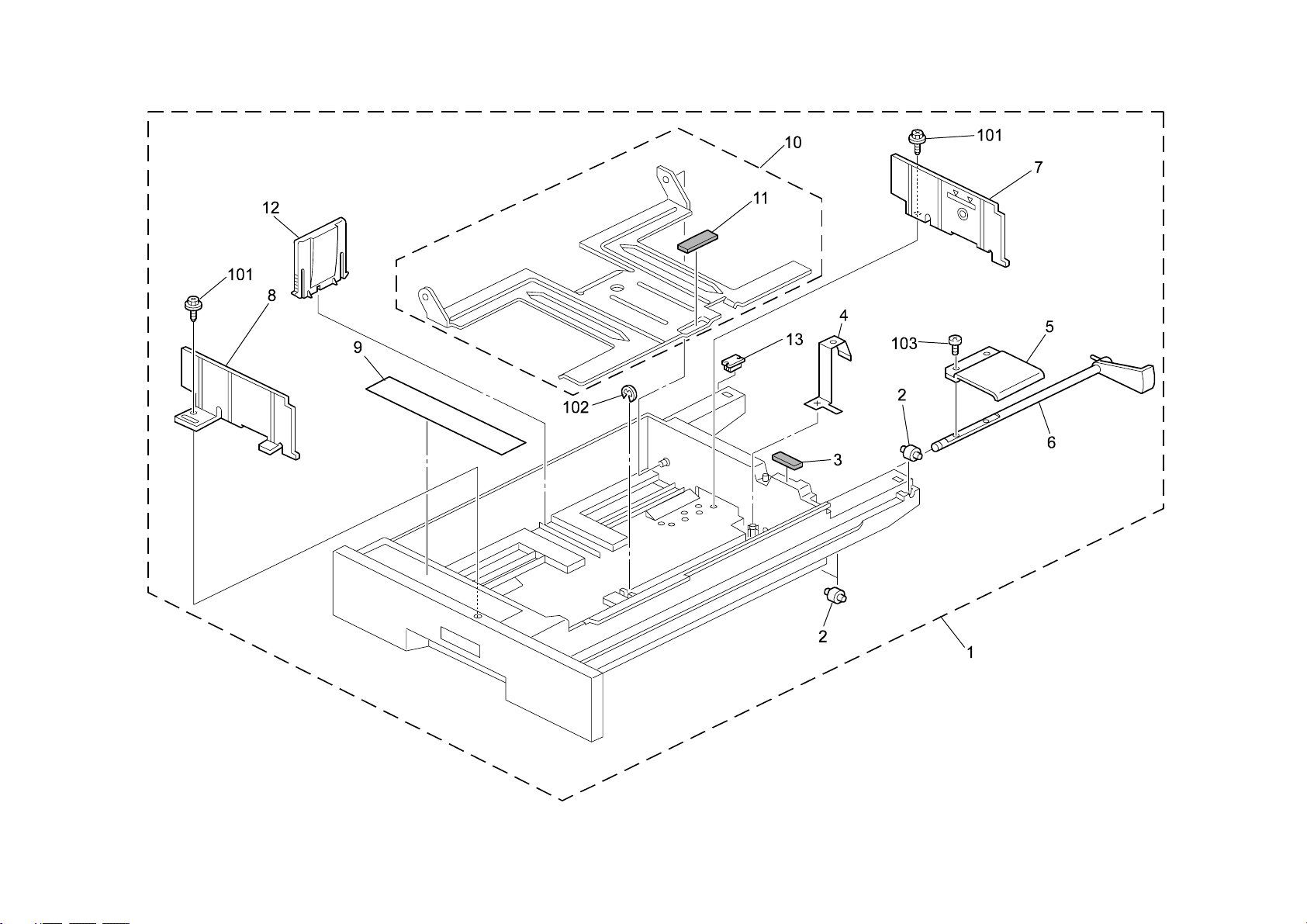
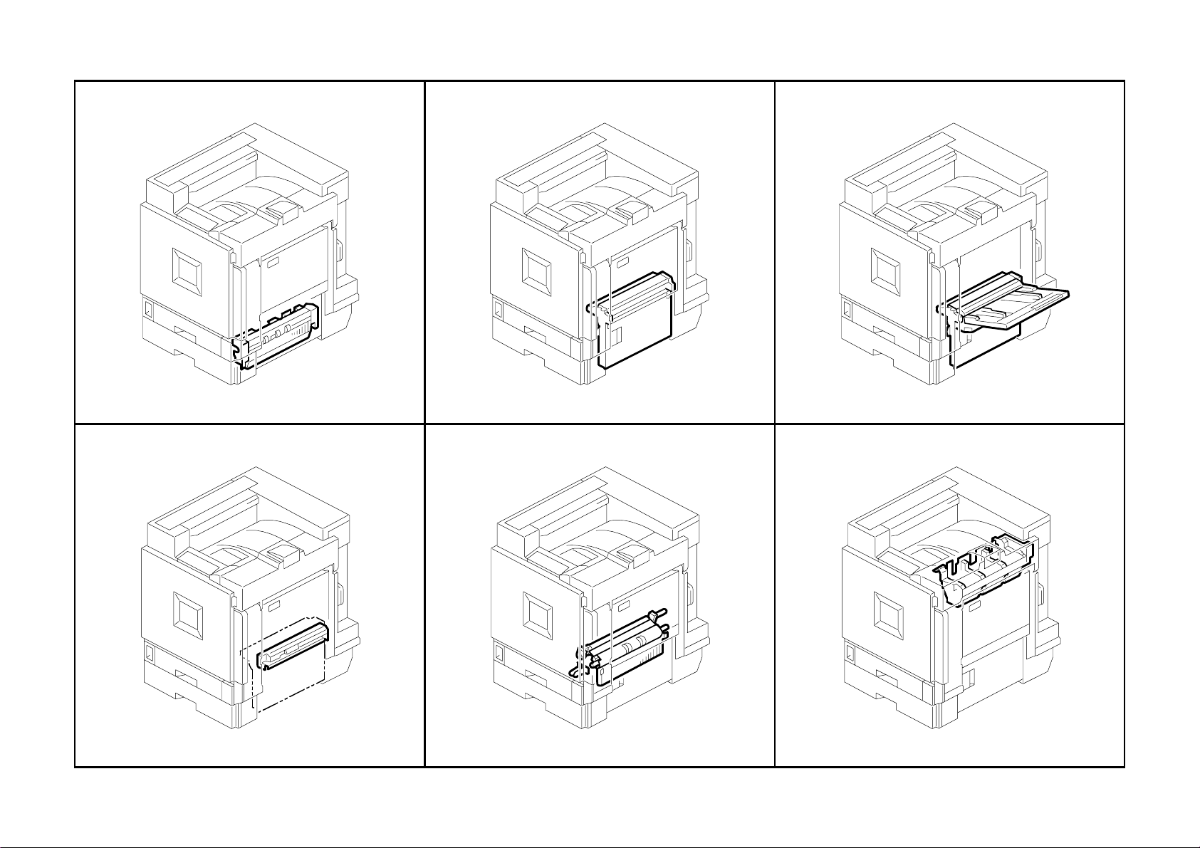
4.1st Cassette (G080)
G080 14 Parts Location and List
Page 31

4.1st Cassette (G080)
Index
No.
1 G080 2768 Paper Tray - No.1 - Ass'y 1
2 A232 2987 Roller - Paper Tray 3
3 G313 2782 Shield 1
4 G060 2775 Spring Plate - Paper Tray 1
5 A204 2972 Bottom Lift Lever 1
6 G060 2774 Lift Shaft 1
7 G080 2778 Side Fence - Rear - Fix - Adhesion 1
8 G080 2777 Side Fence - Front - Fix - Adhesion 1
9 GA00 3066 Decal - Paper Tray - No.1 1
10 G060 2770 Tray Bottom Plate - Ass'y 1
11 AF01 3006 Bottom Plate Pad 1
12 AF01 7023 End Fence 1
13 G080 2526 Shoe Paper Tray 1
Part No.
Description
Q’ty Per
Assembly
Index
No.
101 0450 4008B Tapping Screw - 4x8
102 0720 0060E Retaining Ring - M6
103 0354 0060B Screw - M4X6
Part No.
Description
Q’ty Per
Assembly
G080 15 Parts Location and List
Page 32

5.2nd Cassette (G080)
G080 16 Parts Location and List
Page 33

5.2nd Cassette (G080)
Index
No.
1 G080 2772 Paper Tray - No.2 - Ass'y 1
2 GA00 3068 Decal - Paper Tray - No.2 - Right 1
3 AB01 3868 Gear - 16Z 1
4 A204 2972 Bottom Lift Lever 1
5 G060 2774 Lift Shaft 1
6 A232 2987 Roller - Paper Tray 3
7 G313 2782 Shield 1
8 G060 2775 Spring Plate - Paper Tray 1
9 G060 2797 Paper Size Sensor Board 1
10 G080 2782 Side Fence - Rear - Universal - Ass'y 1
11 A267 2859 Side Fence Stopper 1
12 A267 2860 Rear Lever Stopper 1
13 A267 2857 Spring Plate - Side Fence 1
14 G080 2790 Side Fence - Rear - Universal - Adhesion 1
15 G060 2806 Tension Spring - Paper Size Sensor Board 1
16 G077 2798 Cover - Paper Size Sensor 1
17 G060 2770 Tray Bottom Plate - Ass'y 1
18 AF01 3006 Bottom Plate Pad 1
19 AF01 7024 End Fence - Universal 1
20 G080 2781 Side Fence - Front - Universal - Ass'y 1
21 A134 2976 Stopper Lever 1
22 A134 2978 Spring Plate 1
23 G080 2789 Side Fence - Front - Universal Adhesion 1
24 GA00 3067 Decal - Paper Tray - No.2 Left 1
25 G077 2796 Link - Paper Size Sensor Board 1
Part No.
Description
Q’ty Per
Assembly
Index
No.
101 0452 3008B Tapping Screw - M3x8
102 0450 3008B Tapping Screw - M3x8
103 0720 0060E Retaining Ring - M6
104 0354 0060B Screw - M4X6
105 0450 4008B Tapping Screw - 4x8
Part No.
Description
Q’ty Per
Assembly
G080 17 Parts Location and List
Page 34

6.1st Paper Feed Section (G080)
G080 18 Parts Location and List
Page 35

6.1st Paper Feed Section (G080)
Index
Index
No.
No.
1 G080 2700 Paper Feed Unit - No.1 - Ass'y 1
2 G060 2716 Feed Stay 1
3 AF03 0049 Pick-up Roller 1
4 AB01 1188 Gear - 21Z 1
5 AA10 0014 Retaining Ring C - Separate 2
6 AF03 1049 Feed Roller 1
7 AB01 1218 Gear - Roller Clutch 1
8 AA08 2101 Bushing - 6x10x6 1
9 G080 2761 Arm - Pickup 1
10 AA06 0691 Tension Spring 1
11 AW02 0120 Photointerruptor - Flat 2
12 G080 5483 Harness - Paper Feed Unit 1
13 AA14 0655 Shaft - Paper Feed 1
14 G065 2767 Lever - Feed 1
15 AA08 2102 Bushing - 6x10x6 3
16 A232 2764 Rear Grounding Plate 1
17 5206 2686 Snap Ring 2
18 G065 2776 Release Lever 1
19 G060 2786 Rear Feed Mylar 1
20 AB01 0106 Gear - 24Z 1
21 AA14 0656 Shaft - Gear 1
22 AB01 0107 Gear - 23Z 1
23 AA06 0908 Release Spring 1
24 AA06 0693 Tension Spring 1
25 G065 2774 Pressure Lever 1
26 G065 2775 Link Lever 1
27 G060 2727 Stay - Paper Separation 1 1
28 AF03 2049 Separation Roller 1
29 G060 2900 Torque Limiter - 40mn・m 18mm 1
30 G060 2689 Shaft - Separation Driven 1
31 G060 2724 Upper Guide - Paper Feed Unit 1
32 G080 2763 Ground Plate - Front - Paper Feed Unit 1
33 G060 2723 Housing - Paper Feed Unit 1
34 A232 2766 Feed Mylar 1
35 G080 2762 Guide Plate - Paper Feed Unit 1
Part No.
Part No.
Description
Description
Q’ty Per
Q’ty Per
Assembly
Assembly
Index
Index
No.
No.
36 A232 2762 Paper End Feeler 1
101 0452 3008B Tapping Screw - M3x8
102 0805 0089 Retaining Ring - M4
103 0720 0040E Retaining Ring - M4
104 0720 0060E Retaining Ring - M6
105 0451 3008B Tapping Screw - M3x8
106 0451 3006B Tapping Screw - M3x6
107 0450 3008B Tapping Screw - M3x8
Part No.
Part No.
Description
Description
Q’ty Per
Q’ty Per
Assembly
Assembly
G080 19 Parts Location and List
Page 36

7.2nd Paper Feed Section (G080)
G080 20 Parts Location and List
Page 37

7.2nd Paper Feed Section (G080)
Index
Index
No.
No.
1 G080 2750 Paper Feed Unit - No.2 - Ass'y 1
2 A232 2780 Stay - Paper Feed 1
3 AF02 0404 Transport Roller 1
4 AF03 0049 Pick-up Roller 1
5 AB01 1188 Gear - 21Z 1
6 AA10 0014 Retaining Ring C - Separate 2
7 AF03 1049 Feed Roller 1
8 AB01 1218 Gear - Roller Clutch 1
9 AA08 2101 Bushing - 6x10x6 2
10 G080 2761 Arm - Pickup 1
11 AA06 0691 Tension Spring 1
12 AW02 0120 Photointerruptor - Flat 2
13 G080 5483 Harness - Paper Feed Unit 1
14 AA14 0655 Shaft - Paper Feed 1
15 G065 2767 Lever - Feed 1
16 AA08 2102 Bushing - 6x10x6 3
17 A232 2764 Rear Grounding Plate 1
18 5206 2686 Snap Ring 2
19 G065 2776 Release Lever 1
20 B004 2782 Rear Feed Mylar 1
21 AB01 0106 Gear - 24Z 1
22 AA14 0656 Shaft - Gear 1
23 AB01 0107 Gear - 23Z 1
24 G065 2774 Pressure Lever 1
25 G060 2725 Stay - Paper Separation 1
26 AA06 0908 Release Spring 1
27 AA06 0693 Tension Spring 1
28 G065 2775 Link Lever 1
29 AF03 2049 Separation Roller 1
30 G060 2900 Torque Limiter - 40mn・m 18mm 1
31 G060 2689 Shaft - Separation Driven 1
32 AA08 2104 Bushing - 8x12x7 1
33 A232 2765 Front Grounding Plate 1
34 G060 2760 Housing - Paper Feed Unit 1
35 A232 2766 Feed Mylar 1
Part No.
Part No.
Description
Description
Q’ty Per
Q’ty Per
Assembly
Assembly
Index
Index
No.
No.
36 G080 2762 Guide Plate - Paper Feed Unit 1
37 A232 2762 Paper End Feeler 1
38 G060 2630 Guide Plate - Swivel - Adhesion 1
101 0450 3008B Tapping Screw - M3x8
102 0805 0089 Retaining Ring - M4
103 0720 0040E Retaining Ring - M4
104 0720 0060E Retaining Ring - M6
105 0451 3008B Tapping Screw - M3x8
106 0451 3006B Tapping Screw - M3x6
Part No.
Part No.
Description
Description
Q’ty Per
Q’ty Per
Assembly
Assembly
G080 21 Parts Location and List
Page 38

8.Vertical Transport Section (G080)
G080 22 Parts Location and List
Page 39

8.Vertical Transport Section (G080)
Index
No.
1 G060 2669 Cover - Upper Registration 1
2 G060 2680 Bracket - Micro Switch 1
3 G080 5501 Harness Vertical Transport - Safety Switch 1
4 G060 2686 Registration Driven Roller 1
5 G077 2839 Guide - Remove Paper Dust - Ass'y 1
6 G080 2612 Guide Plate - Registration - Upper 1
7 G080 2614 Guide Plate - Registration - Middle 1
8 G080 2643 Guide Plate - Vertical Transport 1
9 G060 2602 Spring - Registration 2
10 G080 2650 Bushing - Registration - Front - Driven 1
11 G080 2660 Side Plate - Paper Feed - Front - Ass'y 1
12 G080 2670 Hook - Vertical Transport - Upper - Peen 1
13 G060 2674 Torsion Spring - Vertical Transport 1
14 G060 2672 Hook - Lower Vertical Transport 1
15 G080 2673 Shaft - Grip 1
16 G060 2690 Lever - Vertical Transport 1
17 G080 2668 Cover - Vertical Transport 1
18 AW02 0069 Photointerruptor 1
19 G080 5506 Harness - Vertical Transport 1
20 G060 2652 Bushing - M4 4
21 AA06 3616 Spring - 8n 2
22 AF02 3023 Driven Roller - M3xmm17 1
23 G080 2645 Arm - Roller - Release 1
24 G080 2644 DC Solenoid - Ass'y 1
25 G080 2656 Compression Spring - Driven - 2n 2
26 AF02 3022 Driven Roller - M2xmm17 1
27 G060 2663 Side Plate - Paper Feed - Rear - Ass'y 1
28 G060 2683 Lower Vertical Transport Hinge 1
29 G060 2667 Hinge - Vertical Transport 1
30 G060 2651 Rear Bushing - M6 1
Part No.
Description
Q’ty Per
Assembly
Index
No.
101 0451 3006B Tapping Screw - M3x6
102 0720 0040E Retaining Ring - M4
103 0360 3006B Screw - M3X6
104 0450 3008B Tapping Screw - M3x8
105 1105 0511 Harness Clamp - LWS-0306ZC
106 1105 0551 Clamp - Les-0505
107 1105 0487 Harness Clamp
108 0451 3014B Tapping Screw - M3-14
109 1204 2521 Micro Switch
Part No.
Description
Q’ty Per
Assembly
G080 23 Parts Location and List
Page 40

9.Manual Paper Feed 1 (G080)
G080 24 Parts Location and List
Page 41

9.Manual Paper Feed 1 (G080)
Index
No.
1 G080 2531 Transport Sub-unit - Lengthwise - Ass'y 1
2 G060 2973 Front Shaft - Manual Feed Table 1
3 G060 2974 Rear Shaft - Manual Feed Table 1
4 G060 2856 Manual Feed Table Ass'y 1
5 G060 2866 Front Side Fence 1
6 G060 2867 Rear Side Fence 1
7 G060 2908 Pad - Side Fence 2
8 GA00 3010 Decal - Manual Feed 1
9 GA00 3038 Decal - Inkjet Paper Caution 1
10 G060 2905 Paper Guide - Manual Feed Table 1
11 A232 6082 Front Rack 1
12 A232 6083 Rear Rack 1
13 G011 3305 Gear - 16T 1
14 G060 2869 Paper Size Sensor 1
15 G060 2865 Cover - Manual Feed Table 1
16 G080 2953 Torsion Spring - Cover - Left 1
17 GA00 3044 Decal - Vertical Transport 2 1
18 G080 2952 Torsion Spring - Cover - Right 1
19 G060 2940 Cover - Lower Manual Feed 1
Part No.
Description
Q’ty Per
Assembly
Index
No.
101 0802 5291 Tapping Screw - Round Point - M3x6
102 0450 3008H Tapping Screw - M3x8
Part No.
Description
Q’ty Per
Assembly
G080 25 Parts Location and List
Page 42

10.Manual Paper Feed 2 (G080)
G080 26 Parts Location and List
Page 43

10.Manual Paper Feed 2 (G080)
Index
Index
No.
No.
1 AA10 0014 Retaining Ring C - Separate 2
2 AF03 1046 Feed Roller - Manual Feed 1
3 AF03 2046 Separation Roller - Manual Feed 1
4 G080 2900 Torque Limiter 1
5 G080 2851 Manual Feed Unit - Ass'y 1
6 G060 2930 Housing Cover 1
7 AA08 2101 Bushing - 6x10x6 3
8 G080 2683 Shaft - Feed 1
9 G060 2914 Stopper Plate 1
10 AB01 1387 Gear - 23Z 1
11 AF03 0049 Pick-up Roller 1
12 AA06 3568 Pressure Spring 1
13 G060 2932 Pick-up Arm - Manual Feed 1
14 G060 2937 DC Solenoid - Pick-up 1
15 G080 5481 Harness - Manual Feed Unit 1
16 AB01 1418 Gear - 27Z 1
17 AX20 0134 Magnetic Clutch - 245mn・m 1
18 A166 2849 Drive Support Plate 1
19 G080 2651 Link - Pressure Release - Registration 1
20 G080 2652 Bracket - Link - Ass'y 1
21 G080 2649 Slider - Registration - Release 1
22 AA14 3025 Stepped Screw - M3 1
23 G060 2948 Grounding Plate - Reverse 1
24 G060 2931 Feeler - Paper End 1
25 A134 2661 Feeler Roller 1
26 AW02 0120 Photointerruptor - Flat 1
27 G060 2928 Housing - Manual Feed 1
28 G060 2982 Feed Guide 1
29 GA00 3044 Decal - Vertical Transport 2 1
30 G060 2874 Guide Plate - Separator 1
31 AF01 3016 Bottom Plate Pad 1
32 G080 2682 Bushing - Feed 1
33 AA06 3499 Pressure Spring 1
34 G060 2871 Separation Driven Shaft 1
35 AB01 1417 Gear - Separation Driven 1
Part No.
Part No.
Description
Description
Q’ty Per
Q’ty Per
Assembly
Assembly
Index
Index
No.
No.
36 AB01 1416 Gear - 20Z 1
37 AA14 0728 Shaft - Separator - Drive 1
101 0450 3008H Tapping Screw - M3x8
102 0450 3006B Tapping Screw - M3x6
103 0450 3008B Tapping Screw - M3x8
104 0451 3006B Tapping Screw - M3x6
105 0802 5291 Tapping Screw - Round Point - M3x6
106 0720 0040E Retaining Ring - M4
Part No.
Part No.
Description
Description
Q’ty Per
Q’ty Per
Assembly
Assembly
G080 27 Parts Location and List
Page 44

11.Paper Registration (G080)
G080 28 Parts Location and List
Page 45

11.Paper Registration (G080)
Index
No.
1 G080 2684 Bushing - Registration - Front - Mm8 1
2 G060 2685 Registration Drive Roller 1
3 G080 2680 Bushing - Registration - Rear - M8 1
4 5215 2621 Snap Ring - M6 2
5 G080 2605 Guide Plate - Registration - Lower - Adhesion 1
6 AW01 0048 Photosensor - GP2A28N1 1
7 G080 5480 Harness - Registration Sensor 1
8 G060 2609 Bracket - Registration Sensor 1
9 G060 2627 Transport Drive Roller 1
10 G080 2621 Guide Plate - Duplex - Exit - Upper 1
11 AW01 0098 Photointerrupter - GP2A231LRSA 1
12 G080 5482 Harness - Paper Feed Unit - Sensor 1
13 G080 2635 Bracket - Sensor - Paper Feed 1
14 AA06 3408 Spring - 8n 2
15 G060 2652 Bushing - M4 2
16 AF02 2135 Driven Roller - M3x16 1
17 G060 2681 Knob - Vertical Transport 1
18 G060 2626 Transport Drive Roller - Middle 1
19 G060 2617 Middle Guide Plate 1
20 G060 2618 Guide Plate - Middle - Lower - Adhesion 1
21 G060 1277 Bracket - Front Cover Hinge 1
22 A259 6239 Screw - M3X4 1
23 AA08 2101 Bushing - 6x10x6 2
24 AA08 2104 Bushing - 8x12x7 2
25 G060 1054 Holder - Guide Pin - Paper Feed Table 1
26 G080 2622 Guide Plate - Duplex - Exit - Lower 1
27 G080 2623 Guide - Turn 1
Part No.
Description
Q’ty Per
Assembly
Index
No.
101 0451 3006B Tapping Screw - M3x6
102 0313 0060B Philips Pan Head Screw - M3x6
103 0802 5292 Tapping Screw - Round Point - M3x8
104 0720 0040E Retaining Ring - M4
105 0720 0060E Retaining Ring - M6
106 1105 0522 Edge Saddle - Les0510
107 1105 0487 Harness Clamp
108 0450 3006B Tapping Screw - M3x6
Part No.
Description
Q’ty Per
Assembly
G080 29 Parts Location and List
Page 46

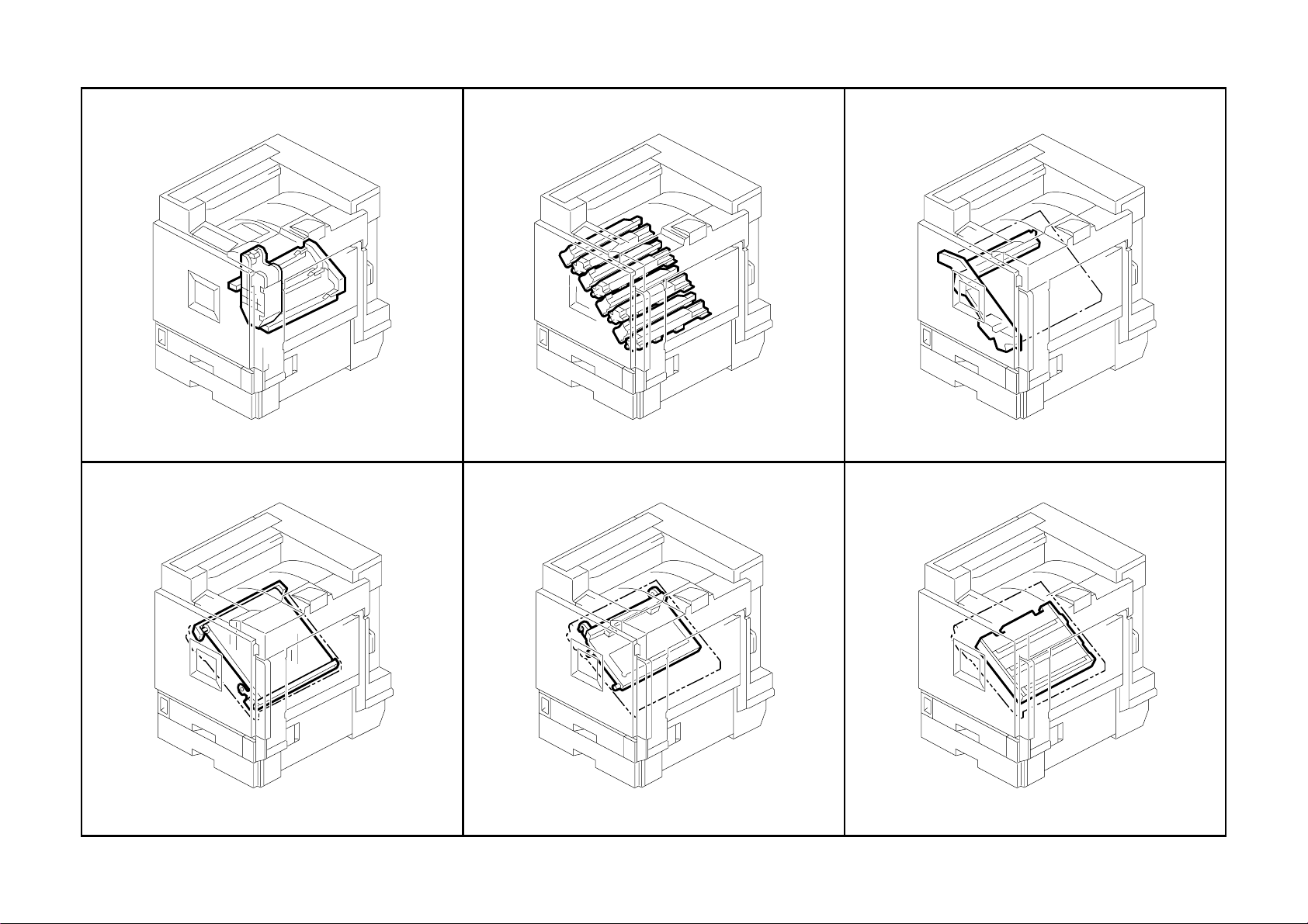
12.Color Toner Hopper (G080)
G080 30 Parts Location and List
Page 47

12.Color Toner Hopper (G080)
Index
No.
1 G080 3201 Holder - Toner Cartridge - Collar - Ass'y 1
2 G080 3215 Tube - Air Pump - BK 1
3 G080 3240 Tube - Air Pump - Y 1
4 G080 3214 Tube - Air Pump - MC 2
5 G080 3241 Tube - Valve - BK 1
6 AA06 3627 Coil - Tube Fuard 1
7 G060 3238 Tube - C Toner Supply 1
8 AA06 3656 Guide Coil - M Tube 1
9 G060 3241 Tube - M Toner Supply 1
10 G060 3237 Tube - Y Toner Supply 1
11 G060 3240 Valve 1
12 G012 4617 Stepped Screw - M3 4
13 G060 3301 Air Pump - Toner Supply 1
14 AW14 0009 Humidity Sensor - RHU-232 1
15 G060 3205 Holder - Toner Cartridge 1
16 G080 3301 Air Pump - Toner Supply 1
17 AW50 0023 Push Switch 1
18 AA15 3461 Holder Seal 3
19 G060 3219 Toner Cartridge Holder 3
20 AA06 3663 Compression Spring - 4.9n 3
21 G080 3216 Nozzle - YMC 3
22 AW02 0132 Optics Sensor - Toner End Sensor 3
23 GA00 3016 Decal - Y Toner Supply 1
24 GA00 3018 Decal - C Toner Supply 1
25 GA00 3017 Decal - M Toner Supply 1
26 G060 5599 Toner Cartridge Stopper 3
27 G060 3232 Base - Toner Cartridge Stopper 3
28 G080 1094 Holder - Toner Supply Unit 1
Part No.
Description
Q’ty Per
Assembly
Index
No.
101 0451 3006B Tapping Screw - M3x6
102 0450 3008B Tapping Screw - M3x8
103 0451 3008B Tapping Screw - M3x8
104 1105 0511 Harness Clamp - LWS-0306ZC
105 1105 0487 Harness Clamp
106 1105 0522 Edge Saddle - Les0510
Part No.
Description
Q’ty Per
Assembly
G080 31 Parts Location and List
Page 48

13.Black Toner Hopper (G080)
G080 32 Parts Location and List
Page 49

13.Black Toner Hopper (G080)
Index
No.
1 G080 5492 Harness - ID - K 1
2 G080 3202 Holder - Toner Cartridge - BK - Dom - Ass'y 1
3 AA15 3461 Holder Seal 1
4 G060 3219 Toner Cartridge Holder 1
5 AA06 3663 Compression Spring - 4.9n 1
6 G080 3222 Nozzle - BK 1
7 G080 3241 Tube - Value - BK 1
8 AW02 0132 Optics Sensor - Toner End Sensor 1
9 G080 5496 Harness - Toner End Sensor - K 1
10 AA06 3627 Coil - Tube Fuard 1
11 G060 3236 Tube - K Toner Supply 1
12 GA00 3019 Decal - K Toner Supply 1
13 G060 5599 Toner Cartridge Stopper 1
14 G060 3232 Base - Toner Cartridge Stopper 1
15 GA00 3033 Decal - Shielding Plate K 1
16 G060 3321 Shielding Plate - Y Development 1
17 GA00 3030 Decal - Shielding Plate Y 1
18 G060 3319 Shielding Plate - C Development 1
19 GA00 3032 Decal - Shielding Plate C 1
20 G060 3320 Shielding Plate - M Development 1
21 GA00 3031 Decal - Shielding Plate M 1
22 G060 1196 Duct - PCU - Supporter - Upper 2
23 G060 1198 PCU Duct 1
24 G060 3318 Shielding Plate - K Development 1
25 G060 3233 Toner Cartridge Holder Filter 2
26 G060 3337 Shield - Holder - Toner Cartridge 1
27 G060 3336 Holder - Toner Cartridge - BK - Left 1
Part No.
Description
Q’ty Per
Assembly
Index
No.
101 0451 3008B Tapping Screw - M3x8
102 0451 3006B Tapping Screw - M3x6
103 1105 0522 Edge Saddle - Les0510
104 0450 3008B Tapping Screw - M3x8
Part No.
Description
Q’ty Per
Assembly
G080 33 Parts Location and List
Page 50

14.PCU/Development Unit (G080)
G080 34 Parts Location and List
Page 51

14.PCU/Development Unit (G080)
Index
No.
1 G211 2005 PCU - CMY 3
2 G219 3003 Development Unit - Y - M-PAC - Ass’y 1
3 G219 3001 Development Unit - C - M-PAC - Ass’y 1
4 G219 3002 Development Unit - M - M-PAC - Ass’y 1
Part No.
Description
Q’ty Per
Assembly
Index
No.
Part No.
Description
Q’ty Per
Assembly
G080 35 Parts Location and List
Page 52

15.Transfer Unit 1 (G080)
G080 36 Parts Location and List
Page 53

15.Transfer Unit 1 (G080)
Index
No.
1 G080 3830 Cleaning Unit - Transfer Belt - Ass'y 1
2 G080 3731 Case - Coating Bar 1
3 G080 3733 Dual Faces Tape - Entrance Seal 1
4 AD04 7034 Entrance Seal - Cleaning 1
5 G080 3732 Shield - Cleaning Unit 1
6 AD04 2047 Brush Roller - Cleaning 1
7 AD04 1081 Cleaning Blade - Ass'y 1
8 G080 3716 Bracket - Cleaning Blade - Ass'y 1
9 AA06 0920 Spring - Blade 1
10 G080 3810 Transfer Unit - Ass'y 1
11 AB01 1480 Gear - Brush Roller - Front 1
12 AB01 1481 Gear - Idler - Cleaning Unit 1
13 G060 3977 Gear - Transport Screw 1
14 G080 3745 Lever - Release - Cleaning Blade 1
15 G080 3740 Holder - Brush Roller - Front - Ass'y 1
16 G080 3831 Casing - Cleaning Unit - Ass'y 1
17 G080 3993 Lever - Release 1
18 G080 3994 Cover - Transfer Unit 1
19 G080 3990 Drum Stay - Transfer Unit - Peen 1
20 G080 3980 Stepper Motor - Transfer Belt - Press Fit 1
21 AA08 0248 Bushing - 6mm 1
22 AB01 0130 Gear - Drive - Brush Roller - Rear 1
23 AD04 3081 Toner Collection Coil - Cleaning 1
24 G060 3952 Shaft - Toner Collection Coil 1
25 G060 3953 Sleeve - Shaft - Toner Collection Coil 1
26 G080 3752 Shutter - Discharge Used Toner 1
27 AA06 3637 Compression Spring - Shutter - Collar 1
28 G080 3751 Cap - Discharge Used Toner - Transfer 1
Part No.
Description
Q’ty Per
Assembly
Index
No.
101 0450 3008B Tapping Screw - M3x8
102 0451 3006B Tapping Screw - M3x6
103 0804 6075 Hexagonal Bolt - M3x8
104 0720 0040E Retaining Ring - M4
105 0451 3008B Tapping Screw - M3x8
Part No.
Description
Q’ty Per
Assembly
G080 37 Parts Location and List
Page 54

16.Transfer Unit 2 (G080)
G080 38 Parts Location and List
Page 55

16.Transfer Unit 2 (G080)
Index
Index
No.
No.
1 G080 3780 Transfer Belt 1
2 G080 3902 Roller - Exit - Press Fit 1
3 G080 3861 Bushing - Transfer Roller 2
4 AA06 3890
5 G080 3855 Transfer Roller 1
6 G060 3852 Bushing - Back-up 2
7 G060 3924 Compression Spring - Back Up 3n 2
8 G060 3680 Back Up Roller - Transfer 1
9 G080 3869 Terminal - Roller - Exit 1
10 G080 3867 Holder - Frame - BK - Front 1
11 G060 3693 Ground Plate - Transfer - K 1
12 G060 3853 Tension Spring - Left Frame 2
13 G080 3860 Frame - BK 1
14 G080 3863 Terminal - Transfer Roller - BK 1
15 G080 3868 Holder - Frame - BK - Rear 1
16 G080 3951 Bracket - Guide - Left - Ass'y 1
17 AA13 2218 Spacer - Bracket - ON-OFF 2
18 G060 3894 Cam - Front 2
19 G080 3936 Shaft - ON-OFF 1
20 G080 3934 Bracket - ON-OFF - Rear - Ass'y 1
21 AA08 2125 Bushing - ON-OFF 2
22 G060 3899 Gear - ON-OFF 1
23 G060 3896 Joint - Front 1
24 G080 3931 Bracket - ON-OFF - Front - Ass'y 1
25 AB01 0128 Gear - Roller - Driven 1
26 G080 3942 Roller - Roller - Driven - Entrance 2
27 G080 3941 Roller - Roller - Driven 2
28 G080 3940 Roller - Driven - Entrance 1
29 AB01 0114 Gear - Bias Roller 1
30 G080 3965 Roller - Bias - Ass'y 1
31 G060 3914 Cover - Bias Roller 1
32 G080 3967 Terminal - Bias 1
33 H519 1157 Bushing 2
34 G080 3968 Terminal - Roller - Bias 2
35 AA06 0931 Tension Spring - Pressure - Bias 2
Part No.
Part No.
Description
Description
Compression Spring -Pressure -Transfer Roller 2
Q’ty Per
Q’ty Per
Assembly
Assembly
Index
Index
No.
No.
36 G080 3960 Guide Plate - Entrance - Transfer 1
37 G060 3677 Lower Transfer Entrance Guide 1
38 G060 3908 Upper Registration Guide 1
39 G080 3950 Bracket - Guide - Right Lower 1
101 0451 3006B Tapping Screw - M3x6
102 0450 3008B Tapping Screw - M3x8
103 0720 0060E Retaining Ring - M6
104 0740 3508 Ball Bearing -8x14x4
105 0720 0040E Retaining Ring - M4
106 0805 3524 Ball Bearing - M3x6x2.5
Part No.
Part No.
Description
Description
Q’ty Per
Q’ty Per
Assembly
Assembly
G080 39 Parts Location and List
Page 56

17.Transfer Unit 3 (G080)
G080 40 Parts Location and List
Page 57

17.Transfer Unit 3 (G080)
Index
No.
1 AA04 3298 Timing Belt - Drive - Transfer Belt 1
2 G080 3910 Drive Roller - Ass'y 1
3 G080 3908 Shaft - Release - Ass'y 1
4 G060 3712 Torsion Spring - Shaft - Release - 10n 1
5 G080 3904 Stay - Left - Ass'y 1
6 AA14 0833 Shaft - Positioning Pin 1
7 G080 3945 Roller - Driven - Left Lower 1
8 G080 3946 Bracket - Roller - Driven - Peen 1
9 AA14 0834 Shaft - Drive - Brush Roller - Transmission 1
10 G080 3920 Roller - Tension 1
11 AA14 0836 Shaft - Positioning Pin - Right 1
12 G080 3900 Stay - Right - Ass'y 1
13 G080 3930 Roller - Driven - Right Lower 1
14 AB03 0739 Pulley - Tightener 1
15 G080 3985 Tightener - Drive - Peen 1
16 AA06 0919 Tension Spring - Tightener 1
17 AB01 0125 Gear - Drive - Brush Roller - Front 1
18 AA08 2101 Bushing - 6x10x6 2
19 AA06 0917 Tension Spring - Tension - Transfer Belt 2
20 G080 3921 Bracket - Roller - Tension - Front 1
21 G080 3890 Frame - Front - Ass'y 1
22 G080 3895 Frame - Rear - Ass'y 1
23 AB01 0127 Gear - Idler Brush Roller - Small 2
24 AB01 0124 Gear - Idler - Brush Roller - Large 1
25 G080 3922 Bracket - Roller - Tension - Rear 1
26 AB01 0130 Gear - Drive - Brush Roller - Rear 1
27 G080 5472 Harness - Transfer Unit - Drawer 1
28 G080 3897 Bracket - Drawer 1
29 G080 3943 Spacer - 0.5mm 1
30 G080 3918 Spacer - M8.2 -0.8mm 1
Part No.
Description
Q’ty Per
Assembly
Index
No.
101 0451 3006B Tapping Screw - M3x6
102 0720 0040E Retaining Ring - M4
103 0720 0060E Retaining Ring - M6
104 0805 3524 Bearing - M3x6x2.5
105 0805 3525 Bearing
106 0450 3008B Tapping Screw - M3x8
107 1105 0511 Harness Clamp - LWS-0306ZC
108 1105 0516 Clamp
109 1102 9387 Connector - Drawer - 51405-2611
Part No.
Description
Q’ty Per
Assembly
G080 41 Parts Location and List
Page 58

18.Transfer Unit 4 (G080)
G080 42 Parts Location and List
Page 59

18.Transfer Unit 4 (G080)
Index
No.
1 G080 3887 Ground Plate - Y - Ass'y 1
2 AA06 3891 Compression Spring - Roller - Back Up 6
3 G080 3862 Bushing - Roller - Back Up 6
4 G080 3898 Roller - Back Up - Ass'y 3
5 AA06 3890
6 G080 3861 Bushing - Transfer Roller 6
7 G080 3855 Transfer Roller 3
8 G080 3923 Ground Plate - Magenta - Ass'y 2
9 G060 3924 Compression Spring - Back Up 3n 2
10 G060 3852 Bushing - Back-up 2
11 G080 3864 Roller - Back Up - Ass'y 1
12 G080 3881 Terminal - Transfer Roller - Magenta 1
13 G060 3956 Rear Spring Plate - Transfer 1
14 G080 3884 Terminal - Earth - Cyan 1
15 G080 3886 Spring Plate - Ground Plate - Cyan 1
16 G080 3875 Ground Plate - Connecting - 1 1
17 G080 3870 Frame - Collar 1
18 G080 3883 Terminal - Earth - Magenta 1
19 G080 3880 Ground Plate - Roller - Back Up 1
20 G060 3955 Front Spring Plate - Transfer 1
21 G080 3882 Terminal - Transfer Roller - Cyan 2
22 G060 5511 Harness - High Voltage Line T-K 1
23 AZ32 0115 Power Pack - T Pack - P2 1
24 G080 5512 Harness - High Voltage Line - T-Y 1
25 AA06 3892 Compression Spring - Earth 1
Part No.
Description
Compression Spring -Pressure -Transfer Roller 6
Q’ty Per
Assembly
Index
No.
101 0450 3008B Tapping Screw - M3x8
Part No.
Description
Q’ty Per
Assembly
G080 43 Parts Location and List
Page 60

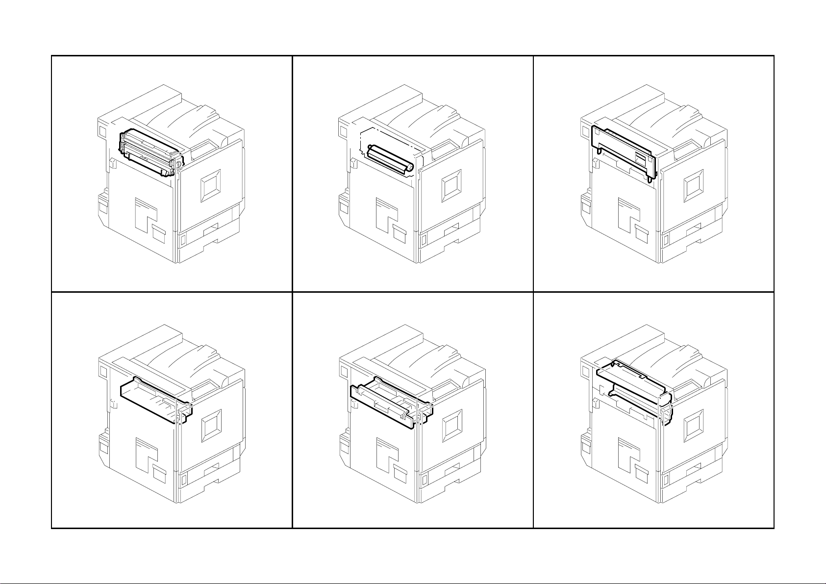
19.Fusing Unit 1 (G080)
G080 44 Parts Location and List
Page 61

19.Fusing Unit 1 (G080)
Index
Index
No.
No.
1 G080 4317 Grip - Fusing Unit 1
2 G080 4308 Tension Spring - Grip 1
3 G080 4323 Sheet - Fiber - Grip 1
4 G080 4315 Supporter - Oil Application Unit - Rear 1
5 G080 4192 Gear - Oil Supply Roller - No.2 1
6 G080 4035 Stay - Fusing - Upper - Ass'y 1
7 G080 4307 Spring Plate - Return 1
8 G080 4309 Supporter - Oil Application Unit - Front 1
9 G080 4194 Gear - Oil Supply Roller - No.1 1
10 G080 4195 Gear - Oil Supply Roller - No.2 - Front 1
11 G060 4208 Fusing Belt 1
12 AX44 0169 Heater - 120V - 700W 1
12 AX44 0176 Heater - 230V - 700W 1
13 G080 4042 Stay - Heat Roller - Ass'y 1
14 G080 4152 Thermostat - Ass'y 1
15 AW10 0077 Thermistor - Fusing 1
16 AB01 2023 Gear - Fusing 1
17 AE03 0044 Ball Bearing - 10x22x6 2
18 AE01 0037 Hot Roller - Mm29 1
19 G080 4251 Knob - Fusing 1
20 G080 4010 Guide Plate - Fusing Exit - Lower - Ass'y 1
21 AA06 6594 Spring - Pickoff Pawl - Pressure Roller 6
22 AE04 4050 Stripper Pawl 6
23 AA14 3520 Shoulder Screw - M3 2
24 G080 4180 Bracket - Pickoff Pawl - Ass'y 1
25 AE04 4051 Pickoff Pawl - Belt - Fusing 5
26 AA06 0932 Tension Spring - Stripper Pawls 5
27 G080 4126 Spring - Pressure - Hot Roller 2
28 G080 4129 Arm - Hot Roller - Rear 1
29 G080 4128 Arm - Hot Roller - Front 1
30 G080 4245 Magnet Catch - Fusing 2
31 G080 4207 Fusing Cover - Upper - Exp - Ass'y 1
32 G060 4190 Nut - Fusing 1
33 G080 4197 Spacer - Heater 1
Part No.
Part No.
Description
Description
Q’ty Per
Q’ty Per
Assembly
Assembly
Index
Index
No.
No.
101 0804 6075 Hexagonal Bolt - M3x8
102 0451 3006B Tapping Screw - M3x6
103 0957 3008B Philips Screw - M3x8
104 0954 3010B Philips Screw - M3x10
105 0450 3008B Tapping Screw - M3x8
106 0725 0100E Retaining Ring C - M10
107 0720 0040E Retaining Ring - M4
Part No.
Part No.
Description
Description
Q’ty Per
Q’ty Per
Assembly
Assembly
G080 45 Parts Location and List
Page 62

20.Fusing Unit 2 (G080)
G080 46 Parts Location and List
Page 63

20.Fusing Unit 2 (G080)
Index
No.
1 AE03 0041 Ball Bearing -20x32x7 2
2 G060 4179 Bracket - Fix - Pressure Roller 2
3 AB01 2022 Gear - Pressure - Drive 1
4 AE02 0120 Pressure Roller 1
5 AX43 0065 Fusing Lamp - 120V 350W 1
5 AX43 0070 Fusing Lamp - 230V 350W 1
6 G080 4012 Thermofuse - Ass'y 1
7 AW10 0083 Thermistor - Pressure 1
8 G080 4202 Shield - Positioning Pin - Front 1
9 G080 4210 Fusing Entrance Guide Plate 1
10 AB01 2021 Gear - Idler - Drive 1
11 G060 4187 Bracket - Gear - Idler 1
12 G060 4188 Sheet - Fiber - Bracket 1
13 G080 4203 Shield - Positioning Pin - Rear 1
14 G077 4070 Bracket - Thermistor 1
15 G060 4190 Nut - Fusing 1
16 G060 4078 Bracket - Stud - Rear - Peen 1
17 GA06 0057 Tension Spring - 9.7n 1
18 G080 4211 Bracket - Connector 1
19 AB01 2024 Gear - Idler - Pressure - Exit - Z19 1
20 G080 4197 Spacer - Heater 1
Part No.
Description
Q’ty Per
Assembly
Index
No.
101 0450 3008B Tapping Screw - M3x8
102 0451 3006B Tapping Screw - M3x6
103 0954 3010B Philips Screw - M3x10
104 0804 6075 Hexagonal Bolt - M3x8
105 0957 3008B Philips Screw - M3x8
106 0725 0200E Retaining Ring C - M20
107 0720 0040E Retaining Ring - M4
108 0353 0040B Screw - M3X4
Part No.
Description
Q’ty Per
Assembly
G080 47 Parts Location and List
Page 64

21.Paper Exit Section 1 (G080)
G080 48 Parts Location and List
Page 65

21.Paper Exit Section 1 (G080)
Index
Index
No.
No.
1 G080 4410 Paper Exit Sub-unit - FU - Ass'y 1
2 G080 4457 Bracket - Magnet Catch - Rear 1
3 AG07 0020 Magnet Catch - 37n 2
4 G080 4439 Gear - Exit Roller - Fu - 18z 1
5 AA08 2075 Bushing - M6 2
6 G080 4451 Gear - Idler - 21z 1
7 G080 4450 Gear - Input - 17z - 19z 1
8 AA08 2101 Bushing - 6x10x6 2
9 G080 4431 Side Plate - Exit - Rear - Peen 1
10 G080 4436 Stay - Exit - Upper 1
11 G080 4440 Guide Plate - Exit - Connecting 1
12 G060 4429 Compression Spring - Exit Driven 1n 2
13 G060 4449 Bushing - M4 4
14 AF04 0593 Roller - Driven - FU 1
15 AF04 0594 Transport Roller - Exit - Vertical Transport 1
16 G080 4441 Link - Gate Pawl - Exit 1
17 G080 4447 Torsion Spring - Gate Pawl - Exit 1
18 G080 4442 Gate Pawl - Exit 1
19 AF04 0592 Exit Roller - FU 1
20 G080 4449 Guide Plate - Exit - Entrance - Lower 1
21 AA14 3716 Stepped Screw 3
22 G080 4437 Stay - Exit - Lower 1
23 AA12 0102 Discharge Brush - Exit 1
24 G060 4496 Support Plate - Discharge Brush 1
25 G080 4430 Cover - Exit 1
26 G080 4444 Cover - Exit - Lock - Duplex 2
27 GA00 1004 Decal - Grip B2 1
28 G080 4435 Side Plate - Exit - Front 1
29 G080 4438 Pulley - Exit Roller - 20t 2
30 G080 4445 Timing Belt - S2m186 1
31 G080 4456 Bracket - Magnet Catch - Front 1
32 G060 4447 Driven Roller - M16 6
33 AF04 0595 Roller - Driven - Connecting 1
34 G060 4436 Compression Spring - Exit Driven 2
35 G080 4452 Roller - Driven - Fusing Exit 1
Part No.
Part No.
Description
Description
Q’ty Per
Q’ty Per
Assembly
Assembly
Index
Index
No.
No.
36 5215 2621 Snap Ring - M6 1
37 G080 4446 Guide Plate - Fusing Exit - Upper 1
101 0451 3006B Tapping Screw - M3x6
102 0450 3008B Tapping Screw - M3x8
103 0805 0089 Retaining Ring - M4
104 0805 0092 Retaining Ring - 3m
Part No.
Part No.
Description
Description
Q’ty Per
Q’ty Per
Assembly
Assembly
G080 49 Parts Location and List
Page 66

22.Paper Exit Section 2 (G080)
G080 50 Parts Location and List
Page 67

22.Paper Exit Section 2 (G080)
Index
No.
1 G080 1099 Bracket - Option - Rear 1
2 G077 5821 Guide Plate - Left Upper - Peen 1
3 G080 4231 Holder - Oil 1
4 G080 4233 Clip - M11 2
5 G080 4232 Tube - Used Developer - Oil 1
6 G080 6041 Bracket - Drawer - Fusing 1
7 G080 1078 Supporter - Fusing Unit 1
8 AW02 0120 Photointerruptor - Flat 1
9 G080 3621 Cover - Density Sensor 1
10 G080 3620 Guide Plate - Transfer - Exit 1
11 G080 3611 Bracket - Density Sensor - Ass'y 1
12 G080 5495 Harness - Sensor - TM 1
13 AA06 0921 Tension Spring - Shutter 1
14 G080 5550 PCB - Density Sensor 1
15 G080 3617 Shutter - Density Sensor - Ass'y 1
16 A259 6239 Screw - M3X4 1
17 G080 1098 Bracket - Option - Front 1
18 G080 3618 Sheet - Shutter 1
19 G080 1079 Holder - Connector - Ass'y 1
Part No.
Description
Q’ty Per
Assembly
Index
No.
101 0802 5291 Tapping Screw - Round Point - M3x6
102 0451 3006B Tapping Screw - M3x6
103 0453 3006B Tapping Screw - M3x6
104 0353 0040B Screw - M3X4
105 1105 0511 Harness Clamp - LWS-0306ZC
Part No.
Description
Q’ty Per
Assembly
G080 51 Parts Location and List
Page 68

23.Paper Exit Section 3 (G080)
G080 52 Parts Location and List
Page 69

23.Paper Exit Section 3 (G080)
Index
No.
1 G080 4470 DC Solenoid - Gate Pawl - Exit - Ass'y 1
2 G060 1091 Rear Fusing Bracket 1
3 GA00 1003 Decal - Grip B1 1
4 GA00 3029 Decal - Vertical Transport 1
5 G060 6040 Cover - Fusing Unit Holder 1
6 G060 6038 Detent Spring 2
7 G060 6033 Rear Holder Arm 1
8 G060 6037 Detent Shaft 2
9 G060 6035 Detent Roller 2
10 G060 6036 Arm Shaft 1
11 G060 6031 Bracket - Rear Lever 1
12 G060 6039 Grip - Cover 1
13 G060 6032 Bracket - Front Lever 1
14 G060 6034 Front Holder Arm 1
15 G080 6021 Holder - Fusing Unit - Peen 1
16 GA00 3055 Decal - Fusing Unit - Positioning Display 1
17 G080 6012 Slide Rail - 110mm 2
18 G060 5823 Bracket - Door Switch 1
19 G060 5822 Bracket - Safety Switch 1
20 G060 5801 Bracket - Door Switch Lever 1
21 G080 5805 Bracket - Auxiliary - Peen 1
22 G080 5807 Lever - Door Switch 1
23 G060 5808 Arm - Safety Switch 1
Part No.
Description
Q’ty Per
Assembly
Index
No.
101 0802 5291 Tapping Screw - Round Point - M3x6
102 0450 3008H Tapping Screw - M3x8
103 0720 0030E Retaining Ring - M3
104 0720 0060E Retaining Ring - M6
105 1105 0511 Harness Clamp - LWS-0306ZC
106 1105 0488 Harness Clamp
107 1105 0516 Clamp
Part No.
Description
Q’ty Per
Assembly
G080 53 Parts Location and List
Page 70

24.Paper Exit Section 4 (G080)
G080 54 Parts Location and List
Page 71

24.Paper Exit Section 4 (G080)
Index
No.
1 G060 4850 Stopper Shaft Bracket 1
2 G077 4464 Bracket - Gear - Floppy Disk - Peen 1
3 G077 4462 Gear - Pulley - 18z27t 1
4 G080 4461 Side Plate - Exit - Fd - Rear 1
5 AB01 2321 Gear - Pulley - 25z -30t 1
6 G060 4463 Timing Belt - S2M176 1
7 AA08 2101 Bushing - 6x10x6 2
8 G060 4455 Guide Plate - Exit Lower 1
9 G060 4454 Driven Roller - M13 2
10 G060 4467 Roller Holder 2
11 AF04 0597 Exit Roller - Floppy Disk 1
12 G060 4457 Bracket - Exit Roller 1
13 G080 4462 Stay - Exit - Floppy Disk - Lower 1
14 G080 4460 Side Plate - Exit - Fd - Front 1
15 G080 4291 Base - Set Sensor 1
16 G080 4292 Electrode - Set Sensor - Machine Or Copier 1
17 G080 5504 Harness - New Article Sensor - Oil 1
18 G080 4463 Stay - Exit - FD - Upper 1
19 G080 1066 Frame - Lengthwise Upper - Peen 1
20 G080 4097 Holder - Guide - Roller 1
21 AA14 3716 Stepped Screw 1
22 A267 3255 Paper Separation Guide 12
23 G060 4098 Shaft - Guide 12
24 G060 4096 Holder - Guide - Rear 1
25 G060 4095 Holder - Guide - Front 1
26 G080 4293 Supporting Plate - Set Sensor 1
Part No.
Description
Q’ty Per
Assembly
Index
No.
101 0451 3006B Tapping Screw - M3x6
102 0802 5291 Tapping Screw - Round Point - M3x6
103 0452 3008B Tapping Screw - M3x8
104 0450 3006B Tapping Screw - M3x6
105 0452 3006B Tapping Screw - M3x6
106 0353 0080B Screw - M3X8
107 0451 3010B Tapping Screw - M3x10
108 1105 0511 Harness Clamp - LWS-0306ZC
109 0720 0040E Retaining Ring - M4
Part No.
Description
Q’ty Per
Assembly
G080 55 Parts Location and List
Page 72

25.Paper Exit Section 5 (G080)
G080 56 Parts Location and List
Page 73

25.Paper Exit Section 5 (G080)
Index
No.
1 G080 4464 Bracket - Idler - Fd - Peen 1
2 AB01 2322 Gear - Idler - 29z 1
3 AB01 2323 Gear - Idler - 19z 1
4 G060 4458 Gear - 16Z 1
5 AA08 2101 Bushing - 6x10x6 1
6 G060 4459 Gate Pawl 1
7 AW02 0120 Photointerruptor - Flat 1
8 G060 4479 Shaft - Paper Sensor 1
9 G060 4482 Feeler - Paper Sensor 1
10 G060 4481 Bracket - Paper Sensor 1
11 AF04 0596 Transport Roller - Floppy Disk 1
12 G060 4451 Upper Exit Guide Plate 1
13 G060 4447 Driven Roller - M16 2
14 G060 4428 Driven Roller - M13 2
15 AA12 0102 Discharge Brush - Exit 1
16 AW02 0121 Photointerruptor - Square 1
17 AA08 2102 Bushing - 6x10x6 1
18 G080 4270 DC Solenoid - Oil Supply - Ass'y 1
19 G060 4460 Lever - Gate Pawl 1
20 G060 4461 Tension Spring - Gate Pawl 1
21 G060 4335 Heat Sink - DC Solenoid Apply 1
22 G080 4237 Plate - Grip 1
Part No.
Description
Q’ty Per
Assembly
Index
No.
101 0802 5291 Tapping Screw - Round Point - M3x6
102 0451 3006B Tapping Screw - M3x6
103 0453 3006B Tapping Screw - M3x6
104 0353 0040B Screw - M3X4
105 1105 0511 Harness Clamp - LWS-0306ZC
106 1105 0522 Edge Saddle - Les0510
107 0720 0040E Retaining Ring - M4
Part No.
Description
Q’ty Per
Assembly
G080 57 Parts Location and List
Page 74

26.Waste Toner Transfer Section (G080)
G080 58 Parts Location and List
Page 75

26.Waste Toner Transfer Section (G080)
Index
No.
1 G080 1072 Supporter - PCU 1
2 G060 1184 Film - PCU Guide Rail 1
3 G080 1071 Supporter - PCU - Peen 1
4 B101 3561 Tube - Connecting - BK 1
5 G080 3603 Guide - Collection Bottle - Ass'y 1
6 G080 3361 Toner Outlet Sub-unit - CY - Sub-ass'y 2
7 G080 3363 Toner Outlet Sub-unit - M - Sub-ass'y 1
8 AA15 3463 Seal - Case M/Y 1
9 B101 3560 Case - Connecting - BK 1
10 G080 3351 Pump - Toner Supply Unit - BK - Sub-ass'y 1
11 G080 3354 Pump - Toner Supply Unit - Y - Sub-ass'y 1
12 G080 3353 Pump - Toner Supply Unit - C - Sub-ass'y 1
13 G080 3352 Pump - Toner Supply Unit - M - Sub-ass'y 1
14 G060 1076 Left Guide - Development Unit 1
15 G060 2972 Safety Switch Feeler 1
16 G060 1074 Upper Registration Stay 1
17 B101 3360 Toner Outlet Sub-unit - BK - Sub-ass'y 1
18 B101 3562 Cover - Connecting - BK - Ass'y 1
Part No.
Description
Q’ty Per
Assembly
Index
No.
101 0451 3008B Tapping Screw - M3x8
102 0451 3006B Tapping Screw - M3x6
Part No.
Description
Q’ty Per
Assembly
G080 59 Parts Location and List
Page 76
27.Drive Section 1 (G080)
G080 60 Parts Location and List
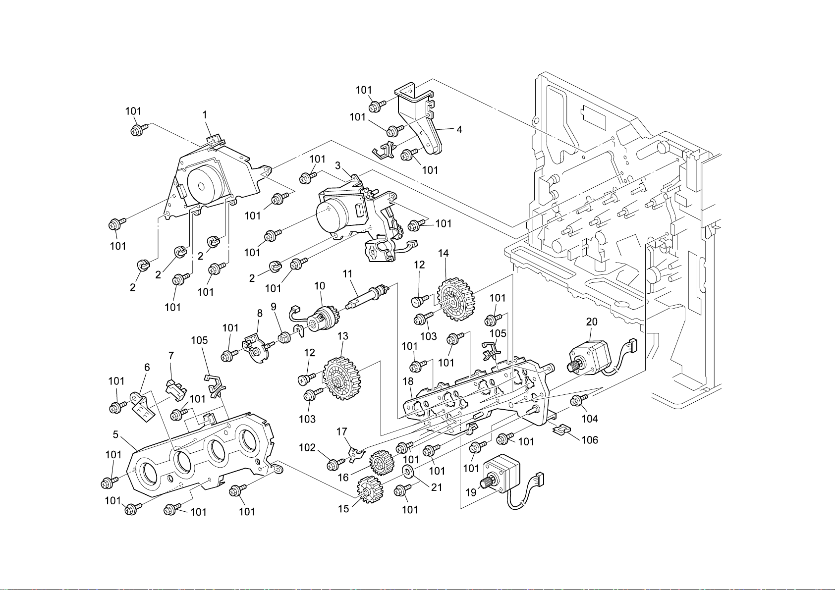
Page 77

27.Drive Section 1 (G080)
Index
No.
1 G060 1120 Drive Unit - C/M/Y Development 1
2 AA08 0257 Bushing - M6 4
3 G077 1100 Drive Unit - K Development 1
4 G060 1199 Inner PCU Duct 1
5 G080 1159 Shielding Plate - Gear - Drum 1
6 G080 1166 Holder - Positioning Sensor - Gear - Drum 2
7 AW02 0120 Photointerruptor - Flat 2
8 G077 1117 Magnetic Clutch Holder 4
9 AA08 2101 Bushing - 6x10x6 4
10 AX20 0244 Magnetic Clutch - Development 4
11 G080 1115 Joint - Development - Sub-ass'y 4
12 G080 1169 Screw - M3 4
13 AB01 0121 Gear - Drum - Z303 - M0.3 2
14 G080 1036 Gear - Drum - Ass'y 2
15 AB01 7633 Gear - Toner Recycling - Z105-t28 1
16 AB01 0122 Gear - Middle - Collar - Z140 1
17 G080 1168 Ground Plate - OPC Drum 4
18 G080 1154 Bracket - Drum - Drive - Peen 1
19 G080 1162 DC Motor - DC2.5V 6.5W 1
20 G080 1160 Stepper Motor - 42 - Black - Ass'y 1
21 AA13 2220 Spacer - Mm8.2 - 1mm 1
Part No.
Description
Q’ty Per
Assembly
Index
No.
101 0451 3006B Tapping Screw - M3x6
102 0450 3008B Tapping Screw - M3x8
103 0951 4008B Philips Screw With Washer - M4x8
104 0451 3005B Tapping Screw - M3x5
105 1105 0511 Harness Clamp - LWS-0306ZC
106 1105 0522 Edge Saddle - Les0510
Part No.
Description
Q’ty Per
Assembly
G080 61 Parts Location and List
Page 78

28.Drive Section 2 (G080)
G080 62 Parts Location and List
Page 79

28.Drive Section 2 (G080)
Index
No.
1 G080 1026 Holder - OPC Drum - Ass'y 4
2 G060 5870 Clamp - M4.8 4
3 G060 5871 Clamp - M3.5 2
4 G060 3706 DC Motor - 1.56W 1
5 AA04 3559 Timing Belt - S2M370 1
6 G080 3630 Joint - Collection Bottle - Ass'y 1
7 G080 5832 Stay - Auxiliary - DRB 1
8 G060 4855 Link Bracket 1
9 5447 2681 Snap Ring 1
10 AW50 0023 Push Switch 1
11 AA14 3219 Stepped Screw 8
12 G060 5530 Harness - Density Sensor 1
Part No.
Description
Q’ty Per
Assembly
Index
No.
101 0451 3008B Tapping Screw - M3x8
102 0451 3006B Tapping Screw - M3x6
103 1102 8519 Connector - MI2 99RH139-9236
104 1105 0487 Harness Clamp
105 1105 0516 Clamp
106 0451 3006H Tapping Screw - 3x6
107 1105 0511 Harness Clamp - LWS-0306ZC
108 1105 0522 Edge Saddle - LES0510
109 1105 0488 Harness Clamp
110 1105 0489 Harness Clamp - LWS 1316
111 1105 0490 Harness Clamp - LWS 2218
Part No.
Description
Q’ty Per
Assembly
G080 63 Parts Location and List
Page 80

29.Drive Section 3 (G080)
G080 64 Parts Location and List
Page 81

29.Drive Section 3 (G080)
Index
No.
1 G060 1087 Rack Holder 1
2 G060 1111 Relay Bracket 1
3 AA06 0862 Tension Spring 1
4 G060 1106 Registration Tightener 1
5 H072 2236 Spacer - M12x6.2 1
6 AB03 0686 Registration Timing Pulley 1
7 5447 2681 Snap Ring 1
8 AB03 0685 Idle Pulley - M15 1
9 G060 1085 Rear Right Channel 1
10 G060 2800 DC Motor - DC24V 0.5W 2
11 G060 5870 Clamp - M4.8 1
12 G060 1053 Drawer Bracket - Paper Feed Table 1
13 G060 1083 Rear Left Channel 1
14 G060 1054 Holder - Guide Pin - Paper Feed Table 2
15 AW50 0023 Push Switch 5
16 G060 2801 Holder - Paper Tray 2
17 G080 5816 Bracket - Switch - Heater 1
18 G080 5519 Harness - Dehumidifier 1
19 G080 5497 Harness - Transfer - Machine Or Copier 1
Part No.
Description
Q’ty Per
Assembly
Index
No.
101 0451 3006B Tapping Screw - M3x6
102 0802 5291 Tapping Screw - Round Point - M3x6
103 0802 5292 Tapping Screw - Round Point - M3x8
104 1105 0511 Harness Clamp - LWS-0306ZC
105 1105 0487 Harness Clamp
106 1105 0490 Harness Clamp - IWS-2218
107 1102 8535 Connector - QR/P17-14P-A
108 1102 9386 Connector - Drawer - 55949-2631
109 1105 0489 Harness Clamp - LWS 1316
110 1105 0488 Harness Clamp
111 1102 8534 Connector - QR/P17-14S-B
112 1105 0516 Clamp
113 1105 0522 Edge Saddle - Les0510
114 1204 2623 Rocker Switch - AJ7100B
Part No.
Description
Q’ty Per
Assembly
G080 65 Parts Location and List
Page 82

30.Drive Section 4 (G080)
G080 66 Parts Location and List
Page 83

30.Drive Section 4 (G080)
Index
No.
1 AB01 7641 Gear - Z28/T35 1
2 AA04 3561 Timing Belt - 40S3M318 1
3 AA10 0013 Snap Ring M6 1
4 AX20 0220 Magnetic Clutch - Registration 1
5 AB03 0690 Timing Pulley - T20 1
6 AB01 7543 Gear - Z25/T26 1
7 AB01 7545 Gear - Z28/Z21 1
8 G080 1161 Positioning Plate - Shaft - Drive - Manual Feed 1
9 G080 1109 Bracket - Drive - Manual Feed - Peen 1
10 AB01 7635 Gear - Z15/Z17 1
11 AB01 7540 Gear - Z28/Z29 1
12 AB01 1241 Gear - Z15 1
13 AB01 7634 Gear - Z18/Z29 1
14 AA04 3925 Timing Belt - S2M668 1
15 AA06 0863 Tension Spring 2
16 G077 1173 Tightener - Paper Feed 1 1
17 G080 1170 Drive Unit -Stepper Motor -Paper Feed -Ass'y 1
18 AB01 7542 Gear - 15Z/30Z 1
19 AA04 3563 Timing Belt - 40S3M162 1
20 AA08 2102 Bushing - 6x10x6 2
21 AX20 0221 Magnetic Clutch - Paper Feed 2
22 AB01 4038 Gear - 22Z 2
23 AB03 0710 Timing Pulley - 20T 1
24 AB01 4037 Gear - 24Z 2
25 G060 1177 Bracket - Magnetic Clutch 2 1
26 G077 1171 Bracket - Paper Feed - Drive 1
27 AB01 7544 Gear - Z25/T20 2
28 G060 1169 Separation Plate - Paper Feed Drive 1
29 G060 1176 Bracket - Magnetic Clutch 1 1
30 AA04 3562 Timing Belt - 40S3M384 1
31 AW02 0120 Photointerruptor - Flat 4
32 G060 1174 Tightener - Paper Feed 1
Part No.
Description
Q’ty Per
Assembly
Index
No.
101 0451 3006B Tapping Screw - M3x6
102 0805 0089 Retaining Ring - M4
103 1105 0488 Harness Clamp
104 1105 0511 Harness Clamp - LWS-0306ZC
105 1105 0487 Harness Clamp
106 1105 0489 Harness Clamp - LWS 1316
107 0720 0040E Retaining Ring - M4
Part No.
Description
Q’ty Per
Assembly
G080 67 Parts Location and List
Page 84

31.Electrical Section 1 (G080)
G080 68 Parts Location and List
Page 85

31.Electrical Section 1 (G080)
Index
No.
1 G060 1555 Upper Controller Duct 1
2 AX64 0123 Fan Motor - DC1.68W 1
3 G077 1556 Lower Controller Duct 1
4 G080 1193 Duct - Guard - DC Motor 1
5 G077 1195 Duct - FFC Spacer 1
6 G080 1182 Duct - Fan - Mm80 1
7 AX64 0103 Fan Motor - DC2.4W 1
8 G077 1560 Duct - Power Supply Unit - Upper Position 1
9 G077 5820 Guide Plate - Upper Rack 1
10 G060 1192 Right Upper Rear Guide 1
11 GZ32 0009 Power Pack - CB 1
12 G080 5508 Harness - Power Pack - CB 1
13 G060 5816 Bracket - Power Pack 1
14 G080 5130 PCB - DRB 1
15 G080 5831 Bracket - DRB 1
16 G080 5833 Bracket - Edge Saddle - DRB 1
17 G060 5862 Cap - PSU 7
18 AZ23 0107 Power Supply Unit - J-P2 - 277W - DOM/NA 1
18 AZ23 0108 Power Supply Unit 277W -EU/AA/CHN 1
19 AA06 3613 Compression Spring 1
20 G060 5861 Inner Back Lever - Door Switch 1
21 AA06 3638 Compression Spring 1
22 AX64 0135 Cooling Fan - 24V 1
23 G060 5863 Bracket - PSU Fan 1
24 G080 5516 Harness - AC - Switch 1
25 G080 5513 Harness - Fusing - Machine Or Copier - AC 1
26 G077 1183 Plate Nut - M3 1
Part No.
Description
Q’ty Per
Assembly
Index
No.
101 0451 3006B Tapping Screw - M3x6
102 0802 5291 Tapping Screw - Round Point - M3x6
103 0954 3008B Philips Screw - M3x8
104 0801 0150 Philips Screw - M4x8
105 0802 5286 Tapping Screw
106 0450 4035B Philips Tapping Screw - M4x35
107 1105 0511 Harness Clamp - LWS-0306ZC
108 1105 0367 Spacer
109 1102 6246 Relay Connector - 4P
110 1105 0522 Edge Saddle - Les0510
111 1105 0544 Edge Saddle - Les2017
112 1107 0629 Fuse (Ceramic Case) - 15A - 125V
113 1107 0908 Fuse - 10A 125V
113 1107 0879 Fuse - 5A 250V (230V)
Part No.
Description
Q’ty Per
Assembly
G080 69 Parts Location and List
Page 86

32.Electrical Section 2 (G080)
G080 70 Parts Location and List
Page 87

32.Electrical Section 2 (G080)
Index
No.
1 G060 5829 Upper Spring Plate - Rack 1
2 G077 5841 Application Rack Ass’y 1
3 G077 5848 Bracket - Harness 1
4 G060 5849 Left Rear Cover 1
5 G080 5451 Harness - Main - Middle 1
6 G080 5852 Panel - Control Board 1
7 G060 5854 Panel Cover - Option 3
8 G060 5853 Grip - Application 1
9 G034 2993 Flanged Hexagonal Head Bolt - M3x6 4
10 G080 5455 Harness - Fusing - Machine Or Copier - Dc 1
11 G080 6120 PCB - J-P2 - ROMDIMM - EXP - Ass'y 1
12 G080 5700 PCB - CTL - J-P2 1
13 G060 5847 Rack - Inner Back Application 1
14 G060 5856 Bracket - Controller Board 1
15 G077 1193 Cover - Duct - Fan - Ass'y 1
16 G080 5454 Harness - Power Supply Unit 1
17 G080 5457 Harness - DRB 1
18 G080 5053 PCB - J-BCU - P2 - Service 1
19 G080 5450 Harness - Main - Lower 1
20 G080 5456 Harness - Main - Left 1
21 G080 5844 Gasket - Rack - Front 1
22 G080 1195 Shading Plate - Cover - Duct - Peen 1
23 G060 9099 Total Counter-RAM-STK12C68-P55 1
Part No.
Description
Q’ty Per
Assembly
Index
No.
101 0451 3006B Tapping Screw - M3x6
102 0353 0060B Philips Pan Head Screw - M3x6
103 1105 0367 Spacer
104 1105 0487 Harness Clamp
105 1105 0489 Harness Clamp - LWS 1316
106 1105 0490 Harness Clamp - IWS-2218
107 1407 5751 IC - NVRAM I2C BUS 64K DIP
Part No.
Description
Q’ty Per
Assembly
G080 71 Parts Location and List
Page 88

33.Frame Section 1 (G080)
G080 72 Parts Location and List
Page 89

33.Frame Section 1 (G080)
Index
No.
1 G080 1460 Guide Plate - Operation Panel 1
2 G060 4820 Relay Guide Plate 1
3 G060 5899 FFC Harness Plate 1
4 G060 5898 FCC Harness Cushion 1
5 AA07 1009 Slide Rail - Left - Ass'y 1
6 G060 1068 Left Guide Plate - Imaging Unit 1
7 G060 3623 Collection Bottle Bracket 1
8 AW02 0121 Photointerruptor - Square 1
9 G080 5493 Harness - Set Sensor - Bottle 1
10 AW50 0025 Set Sensor - Collection Bottle 1
11 AA07 1010 Slide Rail - Right - Ass'y 1
12 G060 1070 Right Guide Plate - Imaging Unit 1
13 G060 4860 Duplex Left Bracket 1
14 G060 4865 Duplex Right Bracket 1
Part No.
Description
Q’ty Per
Assembly
Index
No.
101 0451 3006B Tapping Screw - M3x6
102 0451 3010B Tapping Screw - M3x10
103 1105 0522 Edge Saddle - Les0510
104 1105 0487 Harness Clamp
105 1105 0489 Harness Clamp - LWS 1316
106 1105 0511 Harness Clamp - LWS-0306ZC
107 1105 0488 Harness Clamp
Part No.
Description
Q’ty Per
Assembly
G080 73 Parts Location and List
Page 90

34.Frame Section 2 (G080)
G080 74 Parts Location and List
Page 91

34.Frame Section 2 (G080)
Index
No.
1 G060 1079 Holder - Used Collection Bottle 1
2 G060 3627 Toner Bottle Sensor Feeler 1
3 G060 3629 Shield - Holder - Collection Bottle 1
4 G060 3626 Used Toner Sensor Spring 1
5 G012 4617 Stepped Screw - M3 1
6 G060 2779 Left Supporter 1
7 G060 1089 Front Left Supporting Plate 1
8 G060 1277 Bracket - Front Cover Hinge 1
9 G060 1081 Shielding Plate - Paper Feed 1
10 B004 2995 Cap - Positioning 1
11 G060 2780 Supporter - Right - Ass'y 1
12 G060 2830 Upper Positioning Plate 1
13 G060 2834 Lower Positioning Plate 1
14 G060 1095 Vertical Transport Hinge 1
15 G080 5491 Harness - Sensor - On-off 1
16 AW02 0120 Photointerruptor - Flat 1
17 G060 3998 Seal - Sensor 1
Part No.
Description
Q’ty Per
Assembly
Index
No.
101 0802 5291 Tapping Screw - Round Point - M3x6
102 0451 3006B Tapping Screw - M3x6
103 1105 0522 Edge Saddle - Les0510
Part No.
Description
Q’ty Per
Assembly
G080 75 Parts Location and List
Page 92

35.Frame Section 3 (G080)
G080 76 Parts Location and List
Page 93

35.Frame Section 3 (G080)
Index
No.
1 G080 4358 Oil Tank - Collect - Ass'y 1
2 B051 4361 Cap - Oil Tank Assembly 1
3 G047 4665 Decal - Bottle - Fusing 1
4 G080 4359 Holder - Oil Tank - Ass'y 1
5 G080 4394 Holder - Oil Tank - Ass'y 1
6 G080 4360
7 G080 4370 Valve -Oil -Collect -Machine Or Copier -Ass'y 1
8 G080 4363 Cam - Contact Point 1
9 AG07 1011 Magnet Catch 1
10 G080 4380 Bracket - Sensor 1
11 G080 5505 Harness - Oil - Full 1
12 G024 4740 Oil End Sensor 1
13 AW02 0136 Photointerruptor - Set Sensor 1
14 G080 4384 Bracket - Set Sensor - Oil Tank 1
15 G080 5815 Heat Cover 1
16 AA00 0401 Decal - High Temperature 1
17 AX40 0109 Heater - 120V 9W 1
17 AX40 0110 Heater - 230V 9W 1
18 G080 1082 Guide Plate - Transport Unit 1
19 G060 1099 Supporting Plate - Front Lower 1
Part No.
Description
Bracket -Contact Point -Oil Collection Unit -Ass 1
Q’ty Per
Assembly
Index
No.
101 0802 5291 Tapping Screw - Round Point - M3x6
102 0451 3006B Tapping Screw - M3x6
103 0451 4006B Tapping Screw - 4x6
104 1105 0511 Harness Clamp - LWS-0306ZC
105 1105 0522 Edge Saddle - Les0510
Part No.
Description
Q’ty Per
Assembly
G080 77 Parts Location and List
Page 94

36.Printer Control Board (G080)
G080 78 Parts Location and List
Page 95

36.Printer Control Board (G080)
G080 79 Parts Location and List
Page 96

36.Printer Control Board (G080)
G080 80 Parts Location and List
Page 97

36.Printer Control Board (G080)
G080 81 Parts Location and List
Page 98

36.Printer Control Board (G080)
G080 82 Parts Location and List
Page 99

36.Printer Control Board (G080)
G080 83 Parts Location and List
Page 100

36.Printer Control Board (G080)
G080 84 Parts Location and List
 Loading...