

Page 1

Model J-P2
(Machine Code: G080)
SERVICE MANUAL
Page 2

!IMPORTANT SAFETY NOTICES
PREVENTION OF PHYSICAL INJURY
1. Before disassembling or assembling parts of the printer and peripherals,
make sure that the printer power cord is unplugged.
2. The wall outlet should be near the printer and easily accessible.
3. If any adjustment or operation check has to be made with exterior covers off
or open while the main switch is turned on, keep hands away from electrified
or mechanically driven components.
4. The printer drives some of its components when it completes the warm-up
period. Be careful to keep hands away from the mechanical and electrical
components as the printer starts operation.
5. The inside and the metal parts of the fusing unit become extremely hot while
the printer is operating. Be careful to avoid touching those components with
your bare hands.
HEALTH SAFETY CONDITIONS
Toner and developer are non-toxic, but if you get either of them in your eyes by
accident, it may cause temporary eye discomfort. Try to remove with eye drops
or flush with water as first aid. If unsuccessful, get medical attention.
OBSERVANCE OF ELECTRICAL SAFETY STANDARDS
1. The printer and its peripherals must be serviced by a customer service
representative who has completed the training course on those models.
2. The NVRAM module (option) installed on the controller has a lithium battery
which can explode if replaced incorrectly. Replace the NVRAM only with an
identical one. The manufacturer recommends replacing the entire NVRAM.
Do not recharge or burn this battery. Used NVRAM must be handled in
accordance with local regulations.
3. The optional fax and memory expansion units contain lithium batteries,
which can explode if replaced incorrectly. Replace only with the same or an
equivalent type recommended by the manufacturer. Do not recharge or burn
the batteries. Used batteries must be handled in accordance with local
regulations.
Page 3

SAFETY AND ECOLOGICAL NOTES FOR DISPOSAL
1. Do not incinerate toner bottles or used toner. Toner dust may ignite suddenly
when exposed to an open flame.
2. Dispose of used toner, the maintenance unit which includes developer or the
organic photoconductor in accordance with local regulations. (These are
non-toxic supplies.)
3. Dispose of replaced parts in accordance with local regulations.
4. When keeping used lithium batteries in order to dispose of them later, do not
put more than 100 batteries per sealed box. Storing larger numbers or not
sealing them apart may lead to chemical reactions and heat build-up.
5. Dispose of used fusing oil in accordance with local regulations.
LASER SAFETY
The Center for Devices and Radiological Health (CDRH) prohibits the repair of
laser-based optical units in the field. The optical housing unit can only be repaired
in a factory or at a location with the requisite equipment. The laser subsystem is
replaceable in the field by a qualified Customer Engineer. The laser chassis is not
repairable in the field. Customer engineers are therefore directed to return all
chassis and laser subsystems to the factory or service depot when replacement of
the optical subsystem is required.
!WARNING
Use of controls, or adjustment, or performance of procedures other than
those specified in this manual may result in hazardous radiation exposure.
!WARNING
WARNING: Turn off the main switch before attempting any of the
procedures in the Laser Optics Housing Unit section. Laser
beams can seriously damage your eyes.
CAUTION MARKING:
Page 4

Trademarks
®
Microsoft
, Windows®, and MS-DOS® are registered trademarks of Microsoft
Corporation in the United States and /or other countries.
PostScript
®
PCL
Ethernet
PowerPC
®
is a registered trademark of Adobe Systems, Incorporated.
is a registered trademark of Hewlett-Packard Company.
®
is a registered trademark of Xerox Corporation.
®
is a registered trademark of International Business Machines
Corporation.
Other product names used herein are for identification purposes only and may be
trademarks of their respective companies. We disclaim any and all rights involved
with those marks.
Symbols and Abbreviations
This manual uses the symbols and abbreviations shown below.
Symbol Meaning
☛
!
"
#
SEF Short Edge Feed
LEF Long Edge Feed
"See," "Refer to"
Clip ring
Screw
Connector
Long Edge Feed (LEF)Short Edge Feed (SEF)
Page 5

TABLE OF CONTENTS
1. INSTALLATION........................................................................... 1-1
1.1 INSTALLATION REQUIREMENTS........................................................... 1-1
1.1.1 ENVIRONMENT .............................................................................. 1-1
1.1.2 MACHINE LEVEL ............................................................................ 1-1
1.1.3 MACHINE SPACE REQUIREMENT................................................ 1-2
Main Unit.............................................................................................. 1-2
Main Unit and Finisher ......................................................................... 1-2
CF Expander with Rack ....................................................................... 1-3
CF Expander without Rack .................................................................. 1-3
1.1.4 POWER REQUIREMENTS.............................................................. 1-4
1.2 OPTIONAL UNIT COMBINATIONS.......................................................... 1-5
1.3 INSTALLATION FLOW CHART................................................................ 1-6
Without Optional CF Expander............................................................. 1-6
With Optional CF Expander.................................................................. 1-7
1.4 MACHINE INSTALLATION....................................................................... 1-8
1.5 NOTES FOR TRANSPORTING THE MACHINE.................................... 1-10
1.5.1 MACHINE STANDS....................................................................... 1-10
1.5.2 MACHINE BODY ........................................................................... 1-11
1.6 OPTIONAL UNIT INSTALLATION.......................................................... 1-13
1.6.1 LIST OF OPTIONS ........................................................................ 1-13
1.6.2 PUNCH UNIT INSTALLATION ...................................................... 1-14
Accessory Check ............................................................................... 1-14
Installation Procedure ........................................................................ 1-15
1.6.3 CF EXPANDER RACK .................................................................. 1-18
Accessories Check List ...................................................................... 1-19
Assembling the Rack ......................................................................... 1-20
Docking the Rack and Printer Mainframe........................................... 1-22
1.6.4 CF EXPANDER ............................................................................. 1-24
Accessories Check List ...................................................................... 1-24
CF Expander Installation.................................................................... 1-24
1.6.5 INSTALLING THE HANDSET........................................................ 1-31
1.6.6 40GB HDD..................................................................................... 1-32
Accessories Check List ...................................................................... 1-32
40 GB HDD Installation ...................................................................... 1-32
1.6.7 ARDF ............................................................................................. 1-34
Accessories Check List ...................................................................... 1-34
ARDF Installation ............................................................................... 1-34
1.6.8 MULTI-BIN OUTPUT TRAY........................................................... 1-37
Accessories Check List ...................................................................... 1-37
Installing the Multi-Bin Output Tray .................................................... 1-37
1.6.9 ANTI-CONDENSATION HEATER ................................................. 1-39
2. PREVENTIVE MAINTENANCE................................................... 2-1
2.1 USER MAINTENANCE............................................................................. 2-1
2.2 SERVICE MAINTENANCE....................................................................... 2-3
i
Page 6

3. REPLACEMENT AND ADJUSTMENT........................................ 3-1
3.1 SPECIAL TOOLS................................................................................ 3-1
3.2 IMAGE ADJUSTMENT ............................................................................. 3-2
3.2.1 REGISTRATION.............................................................................. 3-2
Image Area........................................................................................... 3-2
Leading Edge....................................................................................... 3-2
Side to Side.......................................................................................... 3-2
Adjustment Standard............................................................................ 3-2
Paper Registration Standard................................................................ 3-2
Adjustment Procedure.......................................................................... 3-3
3.2.2 COLOR REGISTRATION ................................................................ 3-3
Line Position Adjustment...................................................................... 3-3
Adjustment of Line Speed for Thick Paper........................................... 3-3
3.2.3 PRINTER GAMMA........................................................................... 3-4
Adjustment Overview ........................................................................... 3-4
Adjustment Procedure.......................................................................... 3-4
3.3 EXTERIOR COVERS ............................................................................... 3-5
3.3.1 REAR COVER AND UPPER REAR COVER................................... 3-5
3.3.2 PAPER EXIT TRAY ......................................................................... 3-5
3.3.3 UPPER RIGHT COVER................................................................... 3-5
3.3.4 FRONT COVER............................................................................... 3-6
3.3.5 LEFT COVER AND REAR LEFT COVER........................................ 3-6
3.3.6 UPPER LEFT COVER AND OPERATION PANEL.......................... 3-7
3.4 LASER OPTICS........................................................................................ 3-8
3.4.1 CAUTION DECAL LOCATIONS ...................................................... 3-8
3.4.2 LASER OPTICS HOUSING UNIT.................................................... 3-9
Adjustments after Replacing the Laser Optics Housing Unit.............. 3-12
3.4.3 POLYGON MIRROR MOTOR ....................................................... 3-13
3.4.4 LASER SYNCHRONIZING DETECTOR BOARDS ....................... 3-13
3.5 PCU AND DEVELOPMENT UNIT .......................................................... 3-14
3.6 PAPER FEED......................................................................................... 3-15
3.6.1 PICK-UP, FEED, AND SEPARATION ROLLERS.......................... 3-15
Tray 1 and Tray 2............................................................................... 3-15
By-pass Tray...................................................................................... 3-15
3.6.2 PAPER WIDTH DETECTION BOARD........................................... 3-16
3.6.3 VERTICAL TRANSPORT SENSOR .............................................. 3-17
3.6.4 RIGHT DOOR UNIT....................................................................... 3-17
3.6.5 REGISTRATION SENSOR AND RELAY SENSORS .................... 3-18
3.6.6 PAPER FEED CLUTCHES............................................................ 3-18
3.6.7 BY-PASS FEED CLUTCH ............................................................. 3-19
3.6.8 TRAY LIFT MOTOR....................................................................... 3-19
3.6.9 PAPER FEED MOTOR.................................................................. 3-20
3.7 TRANSFER AND PAPER TRANSPORT UNIT ...................................... 3-21
3.7.1 TRANSFER UNIT .......................................................................... 3-21
3.7.2 TRANSFER BELT CLEANING UNIT............................................. 3-22
3.7.3 CLEANING BLADE AND CLEANING ROLLER............................. 3-23
3.7.4 TRANSFER BELT.......................................................................... 3-25
3.7.5 TRANSFER UNIT DRIVE MOTOR................................................ 3-27
ii
Page 7

3.8 ID SENSORS.......................................................................................... 3-28
3.9 FUSING .................................................................................................. 3-29
3.9.1 FUSING UNIT................................................................................ 3-29
3.9.2 OIL SUPPLY UNIT AND UPPER COVER..................................... 3-30
3.9.3 CLEANING UNIT ........................................................................... 3-31
3.9.4 HEATING ROLLER LAMP............................................................. 3-32
3.9.5 FUSING BELT UNIT...................................................................... 3-33
3.9.6 HOT ROLLER................................................................................ 3-34
3.9.7 HEATING ROLLER........................................................................ 3-34
3.9.8 PAPER GUIDE PLATES AND STRIPPER PAWLS....................... 3-35
3.9.9 THERMISTOR AND FUSE ............................................................ 3-36
3.9.10 PRESSURE ROLLER FUSING LAMP......................................... 3-37
3.9.11 PRESSURE ROLLER.................................................................. 3-38
3.9.12 FUSING UNIT FAN...................................................................... 3-40
3.9.13 WASTE OIL BOTTLE .................................................................. 3-41
3.9.14 PAPER EXIT................................................................................ 3-42
3.10 ELECTRICAL COMPONENTS............................................................. 3-43
3.10.1 MOVING THE CONTROLLER BOX OUT OF THE WAY............. 3-43
3.10.2 MOVING THE HIGH VOLTAGE SUPPLY UNIT - C, B OUT OF THE
WAY 3-43
3.10.3 CONTROLLER AND BCU ........................................................... 3-44
3.10.4 NVRAM REPLACEMENT PROCEDURE .................................... 3-46
NVRAM for BCU ................................................................................ 3-46
NVRAM for Controller ........................................................................ 3-46
NVRAMs for both BCU and Controller ............................................... 3-47
3.10.5 REMOVING THE HIGH VOLTAGE SUPPLY BOARD - C, B....... 3-48
3.10.6 PSU ............................................................................................. 3-48
3.10.7 DRIVER BOARD.......................................................................... 3-49
3.11 DRIVE UNIT ......................................................................................... 3-50
3.11.1 REGISTRATION CLUTCH........................................................... 3-50
3.11.2 DEVELOPMENT CLUTCHES...................................................... 3-50
3.11.3 DEVELOPMENT MOTOR - CMY ................................................ 3-51
3.11.4 DRUM DRIVE MOTOR - CMY AND DRUM DRIVE MOTOR - K . 3-54
3.11.5 DEVELOPMENT DRIVE MOTOR - K.......................................... 3-55
3.12 TONER SUPPLY UNIT......................................................................... 3-57
M Toner Supply Unit .......................................................................... 3-57
C and Y Toner Supply Units............................................................... 3-61
K Toner Supply Unit........................................................................... 3-62
4. TROUBLESHOOTING................................................................. 4-1
4.1 PROCESS CONTROL ERROR CONDITIONS ........................................ 4-1
4.1.1 DEVELOPER INITIALIZATION RESULT......................................... 4-1
4.1.2 PROCESS CONTROL SELF-CHECK RESULT .............................. 4-3
4.1.3 LINE POSITION ADJUSTMENT RESULT....................................... 4-4
4.2 SERVICE CALL CONDITIONS................................................................. 4-7
4.2.1 SUMMARY....................................................................................... 4-7
SC Classification .................................................................................. 4-7
4.3 SC TABLE ................................................................................................ 4-9
iii
Page 8

v
4.4 TROUBLESHOOTING GUIDE ............................................................... 4-43
4.4.1 IMAGE QUALITY........................................................................... 4-43
Work-flow ........................................................................................... 4-43
Detailed Explanation .......................................................................... 4-45
4.4.2 COLOR SHIFT............................................................................... 4-50
Adjustment Standard: Max. 180 mm................................................. 4-52
Preparation......................................................................................... 4-52
How to measure the gap between color lines..................................... 4-58
4.4.3 COLOR SHIFT AFTER TRANSFER UNIT REPLACEMENT......... 4-60
Check the color shift level .................................................................. 4-60
Fusing/ Registration Roller Speed Adjustment................................... 4-60
4.4.4 BLACK OVER PRINT .................................................................... 4-63
Black Over Print Disabled .................................................................. 4-63
Black Over Print Enabled................................................................... 4-63
4.5 ELECTRICAL COMPONENT DEFECTS................................................ 4-64
4.5.1 SENSORS ..................................................................................... 4-64
4.6 BLOWN FUSE CONDITIONS................................................................. 4-66
4.7 LEDS (BCU) ........................................................................................... 4-66
5. SERVICE TABLES...................................................................... 5-1
5.1 SERVICE PROGRAM MODE................................................................... 5-1
5.1.1 ENABLING AND DISABLING SERVICE PROGRAM MODE .......... 5-1
Entering the Service Program Mode .................................................... 5-1
Accessing the Required Program......................................................... 5-2
Inputting a Value or Setting for a Service Program .............................. 5-2
Exiting Service Program Mode............................................................. 5-2
5.1.2 REMARKS ....................................................................................... 5-3
Display on the Control Panel Screen ................................................... 5-3
Others .................................................................................................. 5-4
5.2 SERVICE PROGRAM MODE – CF CONFIGURATION ........................... 5-5
5.2.1 ENABLING AND DISABLING SERVICE PROGRAM MODE .......... 5-5
Entering SP Mode................................................................................ 5-5
Exiting SP Mode................................................................................... 5-5
5.2.2 TYPES OF SP MODES ................................................................... 5-5
SP Mode Button Summary................................................................... 5-6
Switching Between SP Mode and Copy Mode for Test Printing........... 5-7
Selecting the Program Number............................................................ 5-7
Exiting Service Mode ........................................................................... 5-8
5.2.3 REMARKS ....................................................................................... 5-8
Display on the Control Panel Screen ................................................... 5-8
Others .................................................................................................. 5-8
5.3 PRINTER CONTROLLER SERVICE MODE ............................................ 5-9
5.3.1 SERVICE MODE MENU.................................................................. 5-9
5.3.2 BIT SWITCH PROGRAMMING ..................................................... 5-11
5.4 PRINTER ENGINE SERVICE MODE..................................................... 5-12
5.4.1 SERVICE MODE TABLE............................................................... 5-12
SP1-XXX (Feed) ................................................................................ 5-12
SP2-XXX (Drum)................................................................................ 5-21
SP3-XXX (Process)............................................................................ 5-32
i
Page 9

v
SP4-XXX (Scanner) ........................................................................... 5-40
SP5-XXX (Mode)................................................................................ 5-45
SP6-XXX (Peripherals) ...................................................................... 5-60
SP7-XXX (Data Log) .......................................................................... 5-62
5.4.2 INPUT CHECK TABLE .................................................................. 5-76
ARDF Input Check: SP6-007 ............................................................. 5-78
Table 1: Paper Height Sensor............................................................ 5-78
Table 2: Paper Size Switch (Tray 2)................................................... 5-79
Table 3: Paper Size (By-pass Table) ................................................. 5-79
Table 4: Original Size Detection......................................................... 5-79
5.4.3 OUTPUT CHECK TABLE .............................................................. 5-80
5.4.4 TEST PATTERN (SP5-997)........................................................... 5-84
5.5 SCANNER SP ........................................................................................ 5-85
5.5.1 SP MODES.................................................................................... 5-85
SP1-xxx (System and Others)............................................................ 5-85
SP2-XXX (Scanning-image quality) ................................................... 5-86
SP8-XXX (Delivery)............................................................................ 5-93
SP9-XXX (Delivery)............................................................................ 5-94
5.6 REBOOT / SYSTEM SETTING RESET.................................................. 5-95
5.6.1 SOFTWARE RESET...................................................................... 5-95
5.6.2 SYSTEM SETTINGS AND COPY SETTING RESET .................... 5-95
System Setting Reset......................................................................... 5-95
Copier Setting Reset.......................................................................... 5-96
5.7 FIRMWARE UPDATE............................................................................. 5-97
5.7.1 TYPE OF FIRMWARE................................................................... 5-97
5.7.2 ERROR RECOVERY..................................................................... 5-97
Engine Firmware/Controller NIB Firmware......................................... 5-97
Controller System Firmware............................................................... 5-97
5.7.3 CONTROLLER/ENGINE FIRMWARE UPGRADE......................... 5-98
5.8 FIRMWARE UPDATE – CF CONFIGURATION..................................... 5-99
5.8.1 TYPE OF FIRMWARE................................................................... 5-99
5.8.2 ERROR RECOVERY..................................................................... 5-99
5.8.3 FIRMWARE UPGRADE............................................................... 5-100
5.9 NVRAM DATA DOWNLOAD ................................................................ 5-102
NVRAM Data Upload (SP5-824)...................................................... 5-102
NVRAM Data Download (SP5-825) ................................................. 5-102
5.10 CONTROLLER SELF-DIAGNOSTICS................................................ 5-103
5.10.1 OVERVIEW................................................................................ 5-103
5.10.2 DETAILED SELF-DIAGNOSTICS.............................................. 5-104
Without Optional CF Expander......................................................... 5-104
With Optional CF Expander.............................................................. 5-104
5.11 USER PROGRAM MODE................................................................... 5-105
5.11.1 WITHOUT OPTIONAL CF EXPANDER..................................... 5-105
5.11.2 WITH OPTIONAL CF EXPANDER ............................................ 5-106
UP Mode Initial Screen: User Tools/Counter Display....................... 5-106
System Settings ............................................................................... 5-106
Copier/Document Server Features................................................... 5-107
Printer, Facsimile, Scanner Settings ................................................ 5-107
Counter ............................................................................................ 5-108
Page 10

Maintenance..................................................................................... 5-108
5.12 DIP SWITCHES.................................................................................. 5-109
Controller Board............................................................................... 5-109
BCU Board....................................................................................... 5-109
6. DETAILED SECTION DESCRIPTIONS....................................... 6-1
6.1 OVERVIEW .............................................................................................. 6-1
6.1.1 COMPONENT LAYOUT .................................................................. 6-1
6.1.2 PAPER PATH .................................................................................. 6-2
6.1.3 DRIVE LAYOUT............................................................................... 6-3
6.1.4 BOARD STRUCTURE ..................................................................... 6-4
Overview .............................................................................................. 6-4
Descriptions ......................................................................................... 6-5
6.1.5 PRINTING PROCESS ..................................................................... 6-7
6.2 PROCESS CONTROL.............................................................................. 6-9
6.2.1 OVERVIEW...................................................................................... 6-9
6.2.2 POTENTIAL CONTROL .................................................................. 6-9
Overview .............................................................................................. 6-9
Process Control Self Check ............................................................... 6-10
6.2.3 PROCESS CONTROL SELF CHECK PROCEDURE.................... 6-11
Step 1: VSG Adjustment .................................................................... 6-11
Step 2: ID Sensor Solid Pattern Generation....................................... 6-12
Step 3: Sensor Pattern Detection....................................................... 6-12
Step 4: Toner Amount Calculation ..................................................... 6-12
Step 5: VD, VB, VL Selection and VREF Adjustment......................... 6-13
Step 6: ID Sensor Highlight Pattern Generation................................. 6-14
Step 7: Sensor Pattern Density Detection.......................................... 6-14
Step 8: VL (LD Power) Selection........................................................ 6-14
6.2.4 VREF COMPENSATION DURING A PRINT JOB ......................... 6-15
Highlight Pattern................................................................................. 6-15
Adjustment Process ........................................................................... 6-15
6.2.5 TONER SUPPLY CONTROL......................................................... 6-16
Overview ............................................................................................ 6-16
Toner Supply Control Modes.............................................................. 6-16
6.2.6 TONER NEAR END/TONER END DETECTION ........................... 6-17
Introduction ........................................................................................ 6-17
Toner Near End Detection 1............................................................... 6-18
Toner Near End Detection 2............................................................... 6-18
Toner End Detection .......................................................................... 6-19
Toner End Recovery .......................................................................... 6-19
6.2.7 DEVELOPER INITIALIZATION...................................................... 6-20
6.3 LASER EXPOSURE ............................................................................... 6-21
6.3.1 OVERVIEW.................................................................................... 6-21
6.3.2 OPTICAL PATH............................................................................. 6-22
6.3.3 LASER SYNCHRONIZING DETECTOR ....................................... 6-23
Overview ............................................................................................ 6-23
Main Scan Start Detection.................................................................. 6-23
Clock Frequency Adjustment ............................................................. 6-23
vi
Page 11

6.3.4 DUAL BEAM WRITING.................................................................. 6-24
Dual Beam Mechanism ...................................................................... 6-24
Laser Beam Pitch Change Mechanism .............................................. 6-24
Printing Mode and Black LD Unit Position.......................................... 6-25
6.3.5 LD SAFETY SWITCH .................................................................... 6-26
Error Messages.................................................................................. 6-27
6.3.6 AUTOMATIC LINE POSITION ADJUSTMENT.............................. 6-28
Overview ............................................................................................ 6-28
Summary of Each Adjustment............................................................ 6-29
Adjustment Conditions ....................................................................... 6-30
Main Scan Skew Adjustment.............................................................. 6-31
6.4 PHOTOCONDUCTOR UNIT .................................................................. 6-32
6.4.1 OVERVIEW.................................................................................... 6-32
6.4.2 DRIVE............................................................................................ 6-33
6.4.3 DRUM GEAR POSITION SENSORS ............................................ 6-34
Mechanism......................................................................................... 6-34
Initialization Process and SC Codes .................................................. 6-35
6.4.4 DRUM CHARGE AND QUENCHING ............................................ 6-36
6.4.5 DRUM CLEANING......................................................................... 6-37
6.4.6 WASTE TONER COLLECTION..................................................... 6-38
6.4.7 WASTE TONER BOTTLE FULL DETECTION .............................. 6-39
6.4.8 PCU DETECTION (DEVELOPMENT UNIT DETECTION) ............ 6-40
Detection Pins.................................................................................... 6-40
Detection Process.............................................................................. 6-40
Error Message.................................................................................... 6-41
6.5 DEVELOPMENT..................................................................................... 6-42
6.5.1 OVERVIEW.................................................................................... 6-42
6.5.2 DRIVE............................................................................................ 6-43
6.5.3 DEVELOPER AGITATION............................................................. 6-44
6.5.4 DEVELOPMENT BIAS................................................................... 6-45
6.5.5 DEVELOPMENT UNIT DETECTION............................................. 6-45
6.5.6 TONER SUPPLY MECHANISM .................................................... 6-46
Overview ............................................................................................ 6-46
Toner Agitation and Attraction............................................................ 6-46
Air Flow and Toner Flow .................................................................... 6-47
Toner Near End Detection.................................................................. 6-47
Toner Transport ................................................................................. 6-48
6.5.7 TONER CARTRIDGE DETECTION............................................... 6-49
6.6 PAPER FEED......................................................................................... 6-50
6.6.1 OVERVIEW.................................................................................... 6-50
6.6.2 DRIVE – TRAY 1, TRAY 2, AND BY-PASS TRAY ........................ 6-51
6.6.3 PAPER LIFT – TRAYS 1 & 2......................................................... 6-52
6.6.4 PAPER SIZE DETECTION – TRAYS 1 & 2................................... 6-53
6.6.5 PAPER HEIGHT DETECTION – TRAYS 1 & 2 ............................. 6-54
6.6.6 PAPER END DETECTION – TRAYS 1 & 2 ................................... 6-54
6.6.7 REGISTRATION............................................................................ 6-55
6.6.8 PAPER FEED LINE SPEED.......................................................... 6-56
6.6.9 GRIP ROLLER RELEASE MECHANISM....................................... 6-57
vii
Page 12

6.7 IMAGE TRANSFER AND PAPER SEPARATION .................................. 6-58
6.7.1 OVERVIEW.................................................................................... 6-58
6.7.2 TRANSFER BELT DRIVE.............................................................. 6-59
6.7.3 TRANSFER CURRENT ................................................................. 6-60
6.7.4 TRANSFER BELT CLEANING ...................................................... 6-61
6.7.5 TRANSFER BELT CONTACT ....................................................... 6-62
Mechanism......................................................................................... 6-62
Transfer Belt Sensor .......................................................................... 6-63
ACS (Auto Color Sensing) Mode........................................................ 6-64
6.8 FUSING .................................................................................................. 6-65
6.8.1 OVERVIEW.................................................................................... 6-65
6.8.2 FUSING UNIT DRIVE .................................................................... 6-66
Belt and Rollers.................................................................................. 6-66
Fusing Clutch ..................................................................................... 6-66
6.8.3 FUSING TEMPERATURE CONTROL........................................... 6-67
Fusing Temperatures......................................................................... 6-67
Temperature Corrections ................................................................... 6-68
Overheat Protection ........................................................................... 6-68
6.8.4 OIL SUPPLY AND CLEANING ...................................................... 6-69
Oil Supply Pad and Roller .................................................................. 6-69
Oil Supply Mechanism ....................................................................... 6-70
6.8.5 WASTE OIL ................................................................................... 6-71
Bottle Set Sensor ............................................................................... 6-71
Waste Oil Sensor ............................................................................... 6-72
6.8.6 NEW FUSING OIL SUPPLY UNIT DETECTION ........................... 6-73
6.8.7 NEW FUSING UNIT DETECTION................................................. 6-74
6.8.8 ENERGY SAVER MODE............................................................... 6-75
Level 1 Energy Saver Mode............................................................... 6-75
Level 2 Energy Saver Mode............................................................... 6-75
6.9 PAPER EXIT........................................................................................... 6-76
6.9.1 OVERVIEW.................................................................................... 6-76
6.9.2 PAPER OVERFLOW DETECTION................................................ 6-77
6.10 CONTROLLER ..................................................................................... 6-78
6.10.1 OVERVIEW.................................................................................. 6-78
6.10.2 BOARD LAYOUT......................................................................... 6-80
6.10.3 PRINT DATA PROCESSING....................................................... 6-81
RPCS Driver....................................................................................... 6-81
PCL5c Driver...................................................................................... 6-81
PS3 Driver.......................................................................................... 6-82
CMS (Color Management System) .................................................... 6-82
Gray Correction.................................................................................. 6-82
BG/UCR (Black Generation/Under Color Removal) ........................... 6-82
Gamma Correction............................................................................. 6-82
Toner Limitation ................................................................................. 6-83
Dither Processing and ROP/RIP ........................................................ 6-83
6.10.4 CONTROLLER FUNCTIONS....................................................... 6-84
Sample Print....................................................................................... 6-84
Locked Print ....................................................................................... 6-84
Paper Source Selection ..................................................................... 6-85
viii
Page 13

Auto Continue .................................................................................... 6-86
Paper Output Tray.............................................................................. 6-87
Stapling .............................................................................................. 6-88
Punching ............................................................................................ 6-88
6.11 HARD DISK .......................................................................................... 6-89
6.12 IEEE1394 INTERFACE ........................................................................ 6-90
6.12.1 SPECIFICATIONS....................................................................... 6-90
Hardware Specification ...................................................................... 6-90
System Requirements........................................................................ 6-90
6.12.2 IEEE1394 SCSI PRINT................................................................ 6-90
6.12.3 BLOCK DIAGRAM....................................................................... 6-91
6.12.4 PIN ASSIGNMENT ...................................................................... 6-91
6.12.5 REMARKS ................................................................................... 6-92
6.12.6 TROUBLESHOOTING NOTES.................................................... 6-92
6.12.7 IP OVER 1394 ............................................................................. 6-93
6.13 IEEE802.11B (WIRELESS LAN) .......................................................... 6-94
6.13.1 SPECIFICATIONS....................................................................... 6-94
6.13.2 BLOCK DIAGRAM....................................................................... 6-95
6.13.3 TRANSMISSION MODE.............................................................. 6-96
Ad Hoc Mode ..................................................................................... 6-96
Infrastructure Mode............................................................................ 6-96
6.13.4 SECURITY FEATURES............................................................... 6-97
SSID (Service Set ID) ........................................................................ 6-97
Using the SSID in Ad hoc mode......................................................... 6-97
WEP (Wired Equivalent Privacy)........................................................ 6-97
MAC Address..................................................................................... 6-97
6.13.5 TROUBLESHOOTING NOTES.................................................... 6-98
Communication Status....................................................................... 6-98
Channel Settings................................................................................ 6-98
Troubleshooting steps........................................................................ 6-99
6.14 BLUETOOTH (WIRELESS)................................................................ 6-100
6.14.1 SPECIFICATIONS..................................................................... 6-100
6.14.2 BLOCK DIAGRAM..................................................................... 6-100
6.14.3 COMMUNICATION USING BLUETOOTH................................. 6-101
Piconet ............................................................................................. 6-101
Frequency Hopping Spread Spectrum (FHSS) ................................ 6-101
Profiles ............................................................................................. 6-102
6.14.4 SECURITY FEATURES............................................................. 6-102
Public and Private Mode .................................................................. 6-102
PIN Code (Personal Identification Number) ..................................... 6-102
6.15 USB .................................................................................................... 6-103
6.15.1 SPECIFICATIONS..................................................................... 6-103
6.15.2 USB 1.1/2.0................................................................................ 6-103
6.15.3 USB CONNECTORS ................................................................. 6-103
6.15.4 PIN ASSIGNMENT .................................................................... 6-104
6.15.5 REMARKS ................................................................................. 6-104
Related SP Mode............................................................................. 6-104
ix
Page 14

SPECIFICATIONS.................................................................... SPEC-1
1. GENERAL SPECIFICATIONS.............................................................SPEC-1
2. SUPPORTED PAPER SIZES..............................................................SPEC-3
2.1 PAPER FEED ..............................................................................SPEC-3
2.2 PAPER EXIT................................................................................SPEC-4
3. SOFTWARE ACCESSORIES..............................................................SPEC-5
3.1 PRINTER DRIVERS ....................................................................SPEC-5
3.2 UTILITY SOFTWARE ..................................................................SPEC-5
4. MACHINE CONFIGURATION .............................................................SPEC-6
5. OPTIONAL EQUIPMENT ....................................................................SPEC-8
5.1 500-SHEET TRAY .......................................................................SPEC-8
5.2 1000-SHEET TRAY .....................................................................SPEC-8
5.3 2000-SHEET LARGE CAPACITY TRAY .....................................SPEC-8
5.4 TWO-TRAY FINISHER & PUNCH UNIT......................................SPEC-9
5.5 FOUR-BIN MAILBOX.................................................................SPEC-10
5.6 PRINTER WITH CF EXPANDER...............................................SPEC-11
GENERAL SPECIFICATIONS (COPY MODE)...........................SPEC-11
GENERAL SPECIFICATIONS (SCANNER MODE)....................SPEC-15
SOFTWARE ACCESSORIES.....................................................SPEC-17
OPTIONAL EQUIPMENT FOR CF EXPANDER.........................SPEC-17
PERIPHERALS
DUPLEX UNIT (G348)
1. REPLACEMENT AND ADJUSTMENT................................. G348-1
1.1 DUPLEX INVERTER UNIT.................................................................G348-1
1.1.1 TOP COVER..............................................................................G348-1
1.1.2 DUPLEX CONTROL BOARD ....................................................G348-1
1.1.3 DUPLEX INVERTER MOTOR 1 ................................................G348-2
1.1.4 DUPLEX INVERTER MOTOR 2 AND SWITCH.........................G348-2
1.1.5 EXIT SENSOR 3 AND DUPLEX INVERTER SENSOR.............G348-3
1.1.6 EXIT SENSOR 1 AND 2 ............................................................G348-3
1.2 DUPLEX FEED UNIT..........................................................................G348-4
1.2.1 DUPLEX DRIVE BOARD...........................................................G348-4
1.2.2 DUPLEX FEED MOTOR............................................................G348-4
1.2.3 DUPLEX FEED SENSOR..........................................................G348-5
2. DETAILED DESCRIPTIONS ................................................ G348-6
2.1 OVERVIEW ........................................................................................G348-6
2.2 DUPLEX OPERATION .......................................................................G348-7
2.2.1 UP TO A4/LT (81/2" X 11") LEF.................................................G348-7
2.2.2 LARGER THAN A4/LT (81/2" X 11") LEF ..................................G348-7
2.3 DUPLEX INVERTER UNIT.................................................................G348-8
2.3.1 DRIVE........................................................................................G348-8
x
Page 15

2.3.2 FEED TO EXTERNAL EXIT TRAY (NON-DUPLEX MODE)......G348-9
2.3.3 FEED TO DUPLEX FEED UNIT ..............................................G348-10
2.3.4 FEED TO TWO-TRAY FINISHER............................................G348-11
With Optional One-Tray Paper Feed Unit ....................................G348-11
With Optional LCT or Two-Tray Paper Feed Unit.........................G348-11
2.4 DUPLEX FEED UNIT........................................................................G348-12
2.4.1 DRIVE......................................................................................G348-12
2.4.2 FEED-IN AND FEED-OUT.......................................................G348-12
CF EXPANDER (G367)
1. REPLACEMENT AND ADJUSTMENT........................................ 1-1
1.1 SPECIAL TOOLS................................................................................ 1-1
1.2 LUBRICANTS ........................................................................................... 1-1
1.3 IMAGE ADJUSTEMNT ............................................................................. 1-2
1.3.1 PRINTING........................................................................................ 1-2
Leading edge registration..................................................................... 1-2
Side-to-side registration ....................................................................... 1-2
1.3.2 SCANNING...................................................................................... 1-2
Scanner sub-scan magnification .......................................................... 1-2
Scanner leading edge and side-to-side registration ............................. 1-2
Main scan dot position correction......................................................... 1-3
1.3.3 ARDF ............................................................................................... 1-4
ARDF side-to-side and leading edge registration................................. 1-4
1.3.4 PRINTER GAMMA CORRECTION.................................................. 1-5
Printer Mode......................................................................................... 1-5
Copy Mode........................................................................................... 1-7
1.4 REPLACEMENT..................................................................................... 1-10
1.4.1 EXPOSURE GLASS...................................................................... 1-10
1.4.2 ORIGINAL LENGTH/WIDTH SENSOR ......................................... 1-10
1.4.3 SENSOR BOARD UNIT (SBU)...................................................... 1-11
1.4.4 EXPOSURE LAMP STABILIZER................................................... 1-12
1.4.5 XENON LAMP ............................................................................... 1-12
1.4.6 SCANNER POWER SUPPLY UNIT (PSU).................................... 1-14
1.4.7 SCANNER MOTOR ....................................................................... 1-14
1.4.8 FRONT SCANNER WIRE.............................................................. 1-15
1.4.9 REAR SCANNER WIRE ................................................................ 1-18
1.4.10 NVRAM REPLACEMENT PROCEDURE .................................... 1-20
NVRAM on the Controller (IC9).......................................................... 1-20
NVRAM Expansion Board on the Controller (CN13).......................... 1-20
NVRAM on the BCU (IC20)................................................................ 1-21
1.4.11 REQUIRED ACTIONS WHEN REPLACING ITEMS.................... 1-22
1.5 OTHERS................................................................................................. 1-23
1.5.1 TOUCH PANEL POSITION ADJUSTMENT .................................. 1-23
xi
Page 16

2. TROUBLESHOOTING................................................................. 2-1
2.1 SCANNER TEST MODE .......................................................................... 2-1
2.1.1 VPU TEST MODE............................................................................ 2-1
SP4-907-1 VPU Test Pattern: R.......................................................... 2-1
SP4-907-2 VPU Test Pattern: G ......................................................... 2-1
SP4-907-3 VPU Test Pattern: B.......................................................... 2-1
2.1.2 IPU TEST MODE............................................................................. 2-2
SP4-904-1 Register Write/Read Check Result.................................... 2-2
SP4-904-2 Image Path Check Result .................................................. 2-2
3. DETALED DESCRIPTIONS ........................................................ 3-1
3.1 SCANNING............................................................................................... 3-1
3.1.1 OVERVIEW...................................................................................... 3-1
3.1.2 SCANNER DRIVE ........................................................................... 3-2
3.1.3 ORIGINAL SIZE DETECTION ......................................................... 3-3
3.1.4 OTHERS.......................................................................................... 3-5
DC Power Supply................................................................................. 3-5
Anti-Condensation Heater.................................................................... 3-5
3.2 IMAGE PROCESSING ............................................................................. 3-6
3.2.1 OVERVIEW...................................................................................... 3-6
3.2.2 SBU BLOCK DIAGRAM................................................................... 3-7
Signal Processing ................................................................................ 3-7
A/D Conversion.................................................................................... 3-7
White Level Correction:........................................................................ 3-7
Others .................................................................................................. 3-7
Black Level Correction ......................................................................... 3-8
Adjustments ......................................................................................... 3-8
VPU Test Mode.................................................................................... 3-8
3.2.3 IPU BLOCK DIAGRAM.................................................................... 3-9
Shading Correction .............................................................................. 3-9
Picture Element (Dot Position) Correction.......................................... 3-10
Scan Line Correction.......................................................................... 3-10
Image Separation............................................................................... 3-10
Scanner Gamma Correction (RGB Gamma Correction) .................... 3-11
Filtering .............................................................................................. 3-12
ADS (Auto Image Density Selection) ................................................. 3-12
Color Conversion ............................................................................... 3-13
Main Scan Magnification.................................................................... 3-14
Printer Gamma Correction ................................................................. 3-15
Error Diffusion .................................................................................... 3-17
IPU Board Test................................................................................... 3-17
3.3 PRINTER ENGINE ................................................................................. 3-18
3.3.1 DIFFERENCES IN THE PRINTER MAINFRAME.......................... 3-18
3.3.2 PAPER FEED LINE SPEED.......................................................... 3-18
3.3.3 ENERGY SAVER MODES............................................................. 3-19
Overview ............................................................................................ 3-19
Panel Off Mode .................................................................................. 3-20
Auto Off Mode.................................................................................... 3-21
xii
Page 17

3.4 SCANNER FUNCTIONS ........................................................................ 3-22
3.4.1 IMAGE PROCESSING FOR SCANNER MODE............................ 3-22
Image Data Path ................................................................................ 3-22
3.5 HARD DISK DRIVES.............................................................................. 3-23
3.6 IMAGE DATA PATH ............................................................................... 3-24
Copier Application.............................................................................. 3-24
Printer Application.............................................................................. 3-24
Scanner Application (1 bit/8 bits)........................................................ 3-24
Fax Application (Transmission/Reception)......................................... 3-24
xiii
Page 18

17 January, 2003 INSTALLATION REQUIREMENTS
1. INSTALLATION
1.1 INSTALLATION REQUIREMENTS
1.1.1 ENVIRONMENT
1. Temperature Range: 10°C to 32°C (50°F to 89.6°F)
2. Humidity Range: 15% to 80% RH
3. Ambient Illumination: Less than 2,000 lux (do not expose to direct sunlight)
4. Ventilation: 3 times/hr/person or more
5. Avoid exposing the machine to sudden temperature changes, which include:
1) Direct cool air from an air conditioner
2) Direct heat from a heater
6. Avoid installing the machine in areas that might be exposed to corrosive gas.
7. Install the machine at a location lower than 2,500 m (8,200 ft.) above sea level.
8. Install the machine on a strong, level base. (Inclination on any side must be no
more than 5 mm.)
9. Avoid installing the machine in areas that may be subjected to strong vibration.
1.1.2 MACHINE LEVEL
Installation
Front to back: Within 5 mm (0.2")
Right to left: Within 5 mm (0.2")
1-1
Page 19
INSTALLATION REQUIREMENTS 17 January, 2003
A
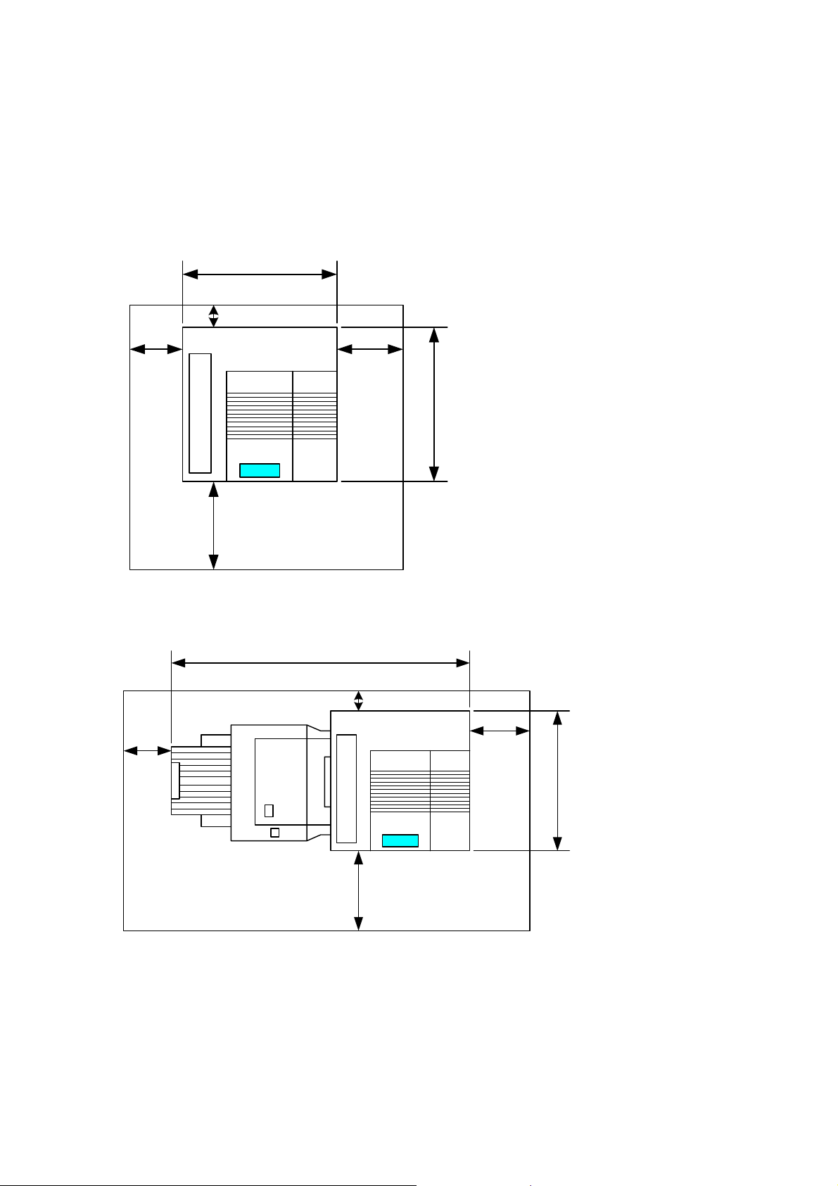
1.1.3 MACHINE SPACE REQUIREMENT
Place the machine near the power source, providing clearance as shown.
Main Unit
575mm
B
A
!
!
!
!
!
!
!
!
!
!
!
!
D
G080I901.WMF
Main Unit and Finisher
!
!
A
1450mm
C
678mm
B: Over 100 mm (4")
C: Over 550 mm (22")
D: Over 700 mm (28")
B
: Over 460 mm (18")
!
!
!
!
!
!
!
!
!
!
!
!
C
678mm
G080I902.WMF
A: Over 460 mm (18")
B: Over 100 mm (4")
D
C: Over 550 mm (22")
D: Over 700 mm (28")
1-2
Page 20
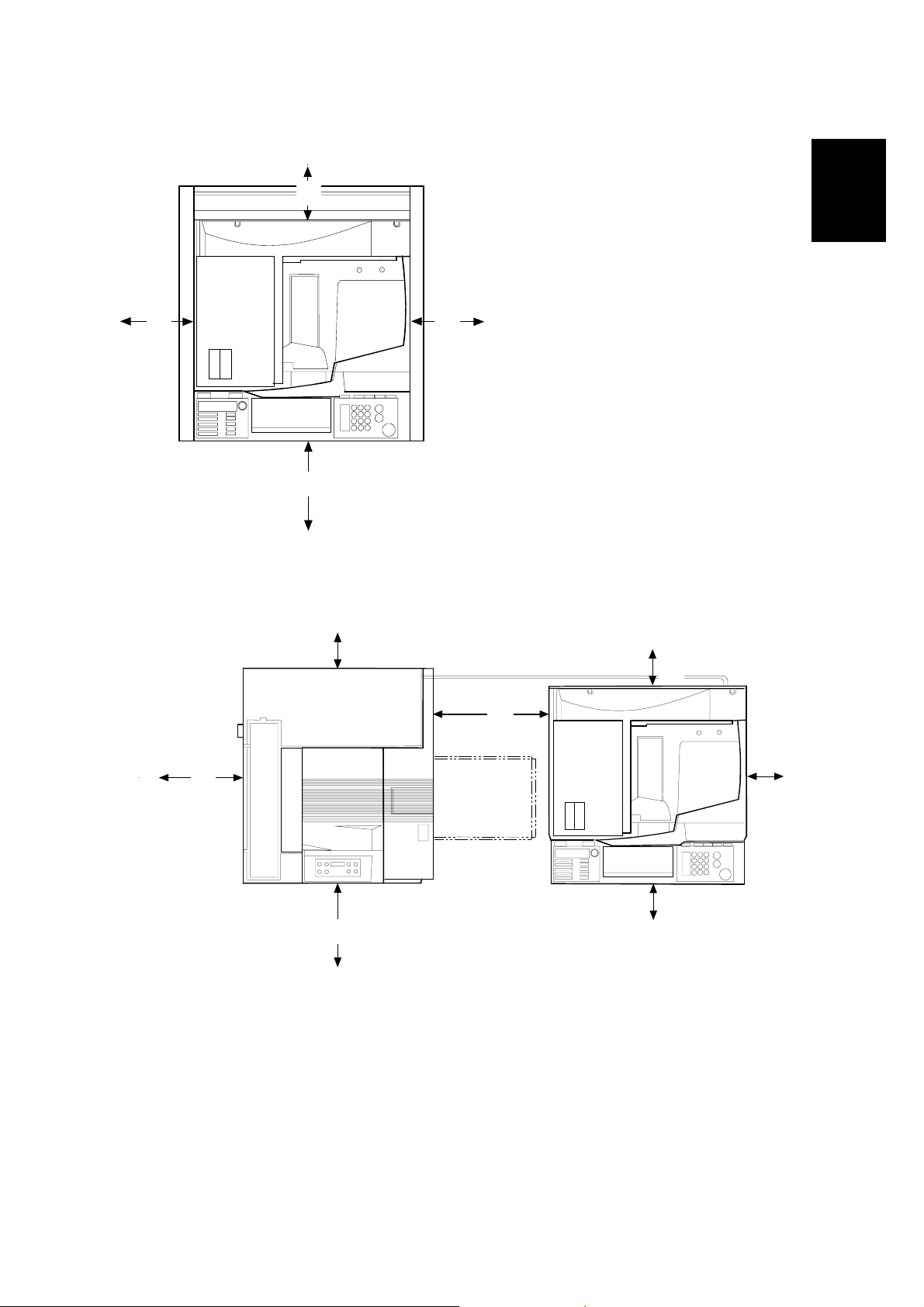
17 January, 2003 INSTALLATION REQUIREMENTS
A
CF Expander with Rack
B
: Over 460 mm (18.1")
from the printer mainframe
B: Over 100 mm (3.9")
A
C
from the printer mainframe
C: Over 550 mm (21.7")
from the printer mainframe
D: Over 700 mm (27.6")
from the printer mainframe
D
G367I901.WMF
Installation
CF Expander without Rack
B
A
F
A: Over 460 mm (18")
B: Over 100 mm (4")
C: Over 100 mm (4")
D: Over 100 mm (4")
C
G
D
E
G367I902.WMF
E: Over 100 mm (4")
F: Over 700 mm (28")
G: Over 450 mm (17.7")
1-3
Page 21

INSTALLATION REQUIREMENTS 17 January, 2003
1.1.4 POWER REQUIREMENTS
!CAUTION
1. Insert firmly the plug in the outlet.
2. Avoid using an outlet extension plug or cord.
3. Ground the machine.
1. Input voltage level: 120 V, 60 Hz: More than 10 A
220 V ~ 240 V, 50 Hz/60 Hz: More than 6 A
2. Permissible voltage fluctuation: ±10 %
3. Do not put or place anything on the power cord.
1-4
Page 22

17 January, 2003 OPTIONAL UNIT COMBINATIONS
1.2 OPTIONAL UNIT COMBINATIONS
Item
No.
1 PFU (1 Tray) Items 2, 3
2 PFU (2 Trays) Items 1, 3
3 LCT Items 1, 2
4
5 3 types of punch
6 Four-bin mailbox Items 4, 5, 15, 20
7 Duplex unit
8 3 types of memory
9 20 GB HDD
10 IEEE 1394 Items 11, 12, 13
11 IEEE 802.11b Items 10, 12, 13
12 USB Items 10, 11, 13
13 Bluetooth Items 10, 11, 12
14 NVRAM
15 CF expander Item 6 Item 18 or 19
16 40GB HDD Option for item 15
17 Rack Item 1, 2, or 3 Option for item 15
18 ARDF Item 19 Option for item 15
19 Platen cover Item 18 Option for item 15
20 Multi-bin output
21 Fax unit Option for item 15
22 G3 additional unit Item 23 Option for item 21
23 G4 unit Item 22 Option for item 21
24 JBIG Option for item 21
25 Handset
Options Alternative Required Remarks
Item 16 and item
17 are
recommended.
See note 2.
Option for item 15
Option for item 21
(U.S. model only)
Two-tray finisher
kit
DIMMs
tray
• Item 7
• Item 8 (Total 128
MB needed), 9,
Item 6, 20
Item 4, 5, 6 Item 7
or 16
• Item 1, 2, or 3
Item 4
Installation
NOTE: 1) Two memory DIMMs (up to 384 MB) can be installed.
2) If the 40GB HDD is not installed, some copier functions such as duplex
copying and sorting, and document server functions cannot be used.
1-5
Page 23

INSTALLATION FLOW CHART 17 January, 2003
1.3 INSTALLATION FLOW CHART
The following flow chart shows how to install the optional units more efficiently.
Without Optional CF Expander
Unpack the printer.
Will the paper feed unit or LCT be installed?
Yes No
Place the printer on the paper feed unit or LCT.
Install the paper feed unit or LCT.
Install the controller options (if required).
Will the duplex unit be installed?
Yes No
Install the duplex unit.
Will the two-tray finisher be installed?
NoYes
Install the punch unit
(if required).
Install the two-tray finisher.
Install the printer.
Install the four-bin mailbox
(if required).
G080I903.WMF
Two-tray Finisher: Needs the duplex unit, HDD or at least 128 MB of memory,
and a paper tray unit or LCT.
Punch Unit: Needs the finisher.
1-6
Page 24

17 January, 2003 INSTALLATION FLOW CHART
With Optional CF Expander
Unpack the printer.
Will the paper feed unit (PFU) or LCT be
installed?
1. Place the printer on the PFU or LCT.
2. Install the PFU or LCT.
Install the controller options (if required).
Install the duplex unit (if required).
Will the rack be installed?
Yes
1. Install the printer.
2. Assemble the rack during printer
initialaization
No
Will the two-tray finisher be installed?
Yes
Install the punch unit (if required).
Install the multi-bin
output tray (if required).
Install the two-tray finisher.
Select the language.
Installation
No
Install the printer
Set the date and time.
Dock the printer and rack.
Clear the memory of IPU/Net file/
Scanner. (SP5-801-10, 12)
Install the CF expander.
Perform ACC.
Install the platen cover or ARDF.
Check magnification and registration.
Adjust the operation panel display if
Set the meter charge mode depending
necessary.
on the service contract.
G080I906.WMF
NOTE: Install the fax unit after making sure that the CF expander works properly.
(☛ “1. Installation” in the service manual for the fax option)
1-7
Page 25

MACHINE INSTALLATION 17 January, 2003
1.4 MACHINE INSTALLATION
Refer to the Operating Instructions. If the customer has made a service contract,
change the settings of the following SP mode menus in accordance with it.
NOTE: 1) The meter charge mode must be enabled for any meter click counter
contract (☛ SP5-930-1).
2) One of the counter methods (developments/prints) must be selected in
accordance with the contract (☛ SP5-045-1).
3) The default of the meter-charge mode is "off."
4) The meter-charge counter cannot be reset.
Item SP No. Function Default
Meter
charge
Counting
method
A3/11" x 17"
double
counting
SP5-930-1 Specifies whether the meter charge mode is
enabled or disabled.
Meter charge mode enabled:
• The Counter menu appears immediately
after the Menu key is pressed.
• The counter type selected by the counting
method (SP5-045-1) can be displayed with
the Counter menu.
• The counter values can also be printed with
the Counter menu.
• The selected counter starts from a negative
number.
• When the ACS mode is on, a monochrome
page is counted as such even if it follows a
color page.
Meter charge mode disabled:
• The Counter menu is not displayed.
• The total counter starts from 0.
• When the ACS mode is on, a monochrome
page is counted as a color page if it follows
a color page.
NOTE: The menu items, "Show Counter" and
"Print," appear in the UP mode after
the meter charge mode (SP5-930-1) is
enabled or the optional CF expander
is installed. (These menu items
always appear after the CF expander
is installed.)
SP5-045-1 Specifies whether the counting method used
in meter charge mode is based on
developments or prints.
Important:
This SP can only be done before the negative
counters are reset with SP7-825-001.
SP5-104-1 Specifies whether the counter is doubled for
A3/11" x 17" paper.
"OFF"
"0":
Developments
"No": Single
counting
1-8
Page 26

17 January, 2003 MACHINE INSTALLATION
Item SP No. Function Default
PM warning
display 1
SP5-930-3 Specifies whether the PM warning for the
PCUs, development units, and fusing unit is
"Click 1"
displayed when the replacement time arrives.
Click 1: Displayed
Click 2: Not displayed
PM warning
display 2
Fax No.
setting
SP5-930-4
to
SP5-930-5
Specifies whether the PM warnings for the
paper feed roller, transfer unit, and transfer
cleaning unit are displayed.
SP5-812-2 Programs the service station fax number.
The number is printed on the counter list when
"No Alert": Not
displayed
the meter charge mode is selected, so that the
user can fax the counter data to the service
station.
Counter
reset
SP7-825-1 Resets the counters to "0."
Important: This must be done at installation
after all the above settings have been
finished. The negative counters used in the
meter charge mode will be reset to zero.
Installation
1-9
Page 27
NOTES FOR TRANSPORTING THE MACHINE 17 January, 2003
1.5 NOTES FOR TRANSPORTING THE MACHINE
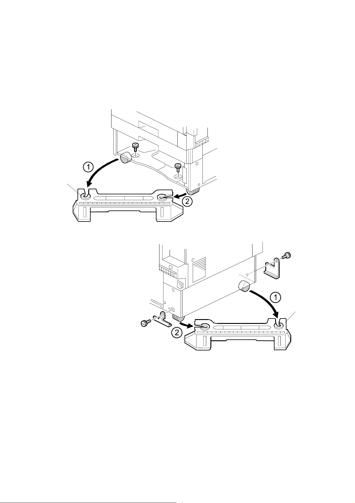
1.5.1 MACHINE STANDS
If it is difficult to slide the machine across the floor after installing the optional paper
feed unit or LCT, remove the two stands with the following procedure.
[A]
G080I910.WMF
[B]
G080I911.WMF
1. Remove all trays in the optional paper feed unit or LCT.
2. Remove the front stand [A] (! x 2).
3. Remove the rear stand [B] (! x 2, 2 brackets).
CAUTION: Reinstall the two stands in their original positions, or the machine might
tip over when drawing out the paper trays and so on.
1-10
Page 28

17 January, 2003 NOTES FOR TRANSPORTING THE MACHINE
1.5.2 MACHINE BODY
!CAUTION
Fix the transfer belt in its position before moving the machine, otherwise
the transfer belt and the black PCU may be damaged.
Before transporting the machine for both short and long hauls, return it to its
original condition.
1. Remove the toner cartridges to prevent toner from flowing into the toner supply
tube due to vibrations experienced during transport. This may cause the tube to
be clogged with toner.
2. Put air packing into the toner cartridge holder to shield the toner supply
entrance. This prevents toner from flowing out to the toner cartridge holder.
3. Set the lock pin (which comes with the machine) in the transfer belt unit.
NOTE: The lower end of the transfer belt moves. The surfaces of the belt and
PCU may be damaged by the friction between them if you transport the
machine without locking the belt.
Installation
4. Make sure there is no paper left in the paper trays and fix down the bottom
plates with a sheet of paper and tape.
5. Empty out the waste toner bottle and attach securing tape to prevent the bottle
from coming out.
6. Empty out the waste oil bottle and attach securing tape to prevent the bottle
from coming out.
[A]
G080I904.WMF
7. Turn the release lever [A] counterclockwise to its lowermost position. (The lever
does not stay in this position if you do not hold it.) Stick the lever in this position
with tape.
NOTE: The release lever lifts the transfer belt up and presses it against the
black PCU. The surfaces of the belt and PCU may be damaged by the
friction between them if you transport the machine with the two units in
this position.
1-11
Page 29

NOTES FOR TRANSPORTING THE MACHINE 17 January, 2003
8. Attach shipping tape to the covers and doors, or shrink-wrap the machine
tightly.
NOTE: 1) If pre-installing machines for some test prints at a service depot, use a
jig oil supply unit, and not the oil supply unit enclosed as an accessory.
This is because the toner supply system uses a touch-and-release
mechanism, which can cause the unit to move freely up and down
during transport if shipping the mainframe with the oil supply unit
installed. This in turn may cause damage to the white holder on the
fusing unit. However if simply moving the machine from floor to floor, the
oil supply unit can be left installed.
2) If shipping a used machine to a new location, dispose of the used oil
supply unit and install a new one because of the reason explained
above. This is not necessary when simply moving the machine from
floor to floor.
3) Whenever having moved the machine to a new location, be sure to
perform Auto Adjust (User Program mode) or forced Line Position
Adjustment (SP5-993-002) to optimize color line alignment.
4) Make sure that the side fences in the trays are properly positioned to
prevent color shifting.
1-12
Page 30

17 January, 2003 OPTIONAL UNIT INSTALLATION
1.6 OPTIONAL UNIT INSTALLATION
1.6.1 LIST OF OPTIONS
The available printer options are listed below. Installation is explained in the
Operating Instructions. This list does not include the CF expander and its options.
• Paper Feed Unit (500 sheets x 1)
• Paper Feed Unit (500 sheets x 2)
• Large Capacity Tray
• Two-tray Finisher
• Four-bin Mailbox
• DIMM Memory (64/128/256 MB)
• IEEE1394
• IEEE 802.11b
• USB
• Bluetooth
• 20GB HDD
• NVRAM
Installation
1-13
Page 31

OPTIONAL UNIT INSTALLATION 17 January, 2003
1.6.2 PUNCH UNIT INSTALLATION
Accessory Check
Check the quantity and condition of the accessories in the box against the following
list:
Description Q’ty
1. Punch unit ............................................................................. 1
2. Sensor arm ........................................................................... 1
3. Hopper .................................................................................. 1
4. Step screw ............................................................................ 1
5. Spring.................................................................................... 1
6. Spacer (2 mm) ...................................................................... 1
7. Spacer (1 mm) ...................................................................... 1
8. Tapping screw....................................................................... 1
9. Tapping screw....................................................................... 2
1-14
Page 32

17 January, 2003 OPTIONAL UNIT INSTALLATION
Installation Procedure
[A]
Installation
B377I102.WMF
[C]
B377I103.WMF
!CAUTION
Switch off the main machine and unplug its power cord. If the two-tray
finisher has been installed, disconnect it and pull it away from the machine.
1. Unpack the punch unit and remove all tapes and shipping retainers.
2. Open the front door and remove the rear cover [A] (! x 4).
3. Remove the bracket [B] (! x 2) and paper guide [C] (stepped ! x 1).
[B]
1-15
Page 33

OPTIONAL UNIT INSTALLATION 17 January, 2003
[B]
[A]
[C]
B377I101.WMF
[E]
4. Remove the hopper cover [A] (! x 2).
5. Install the sensor bracket [B] (stepped ! x 1).
6. Install the spring [C].
7. Install the 2 mm spacer [D].
8. Install the punch unit [E] (! x 2, stepped ! x 1).
1-16
B377I104.WMF
[D]
Page 34

17 January, 2003 OPTIONAL UNIT INSTALLATION
[A]
B377I200.WMF
Installation
[B]
B377I106.WMF
9. Connect the harnesses [A] and clamp them as shown.
10. Slide in the hopper [B].
11. Fasten the two 1-mm spacers [C] to the rear frame for future adjustment.
NOTE: The spacers are used to adjust the horizontal positioning of the punch
holes.
12. Reassemble the finisher and check the punch operation.
[C]
1-17
Page 35

OPTIONAL UNIT INSTALLATION 17 January, 2003
1.6.3 CF EXPANDER RACK
NOTE: 1) Section 1.6.4 shows the procedure for installing the Copier Feature
Expander in a machine equipped with the optional rack. Before installing
the CF expander, you must install the rack.
2) For the printer mainframe and printer option installation procedures,
please refer to the Operating Instructions "Set-up Guide."
3) To avoid a possible build-up of ozone, make sure to install the machine
in a room that is well ventilated.
!CAUTION
Rating Voltage:
G367I914.WMF
Rating voltage of output connector;
For the ARDF
Maximum DC 24V
G367I208.WMF
Rating voltage of I/F harness connector;
Scanner I/F Harness
Maximum DC 24V
1-18
Page 36

17 January, 2003 OPTIONAL UNIT INSTALLATION
Accessories Check List
Description Q'ty
1. Left Side Stand ..................................................................... 1
2. Right Side Stand ................................................................... 1
3. Table Board .......................................................................... 1
4. Backboard............................................................................. 1
5. Left Arm ................................................................................ 1
6. Right Arm .............................................................................. 1
7. Left Securing Bracket............................................................ 1
8. Right Securing Bracket ......................................................... 1
9. Grounding Wire..................................................................... 2
10. Grounding Bracket................................................................ 1
11. Large Thumb Screw.............................................................. 4
12. Small Thumb Screw.............................................................. 4
13. Spacer................................................................................... 2
14. Screw (M6 x 10).................................................................... 14
15. Screw (M4 x 6)...................................................................... 4
16. Washer.................................................................................. 4
17. Spring Washer ...................................................................... 4
18. Clamp.................................................................................... 1
Installation
1-19
Page 37

OPTIONAL UNIT INSTALLATION 17 January, 2003
Assembling the Rack
1. Insert a screw [A] about half way into
the center holes of both the left [B]
[B]
and right [C] side stands.
2. Hook the center part of the
backboard onto the 2 screws.
[C]
3. Making sure that the two side stands
are parallel, insert the remaining
screws, then tighten all 6 screws.
4. With the 2 square holes [D] in the table
board in front of you as shown, attach the
left [E] and right [F] arms. When attaching
the right arm, secure the ground wires [G]
with screws [H] as shown.
NOTE: Please make sure to orient the
table with the square holes toward
you.
[A]
[D]
[H]
G367I101.WMF
[E]
[F]
[G]
G367I102.WMF
1-20
Page 38

17 January, 2003 OPTIONAL UNIT INSTALLATION
[E]
[A]
[B]
[C]
[D]
[F]
[H] [I]
[G]
G367I103.WMF
5. Set the table board [A] on the stand as shown.
NOTE: 1) Make sure that the screw holes for the scanner unit are positioned
at the right rear [C] and left front [B] of the table board.
2) Recommended attachment positions for the table board:
• Machine with Two-tray Paper Supply Unit & LCT: 2nd hole from
the top
• Machine with One-tray Paper Supply Unit: 6th hole from the top
3) When attaching the table board at a position lower than the
recommended one, make sure the upper right cover can be opened
and the toner cartridges (especially black) can be replaced.
When attaching the table board below the recommended position, it
is necessary to shift the printer mainframe 10 cm (3.9") toward the
front so that the upper right cover can be opened for toner
replenishment.
G367I903.WMF
Installation
6. Align the cushion [D] (enclosed as accessories for the optional CF Expander)
as follows and attach it to the backboard [E]:
• Align the top side with the bottom end of the lowermost slot of the right side
stand [F].
• Align the right side with the left side of the right side stand [G].
NOTE: The cushion prevents the right side stand [I] from damaging the
scanner cable [H]. The cushion can be ineffective if attached to an
incorrect position.
1-21
Page 39

OPTIONAL UNIT INSTALLATION 17 January, 2003
7. Secure the two grounding wires [A]
(! x 2 each). There is a wire at the left
side and one at the right side.
8. Attach the securing brackets [B] to the
left and right arms as shown (1 thumb
screw [C] for each).
Docking the Rack and Printer Mainframe
NOTE: If the Finisher is going to be
installed, the mounting bracket of
the rail should be attached after
docking the mainframe with the
rack. In addition, the Finisher
should be attached after docking
is complete.
[B]
[A]
[C]
G367I104.WMF
1. Remove the paper tray and front
stand [A] from the paper feed unit as
shown (! x 2).
[A]
G367I201.WMF
2. Remove the brackets [B] and rear
stand [C] (! x 1 for each).
3. Reinsert the paper tray.
NOTE: Since the front and rear
[B]
stands will no longer be
necessary, dispose of them
according to local
regulations.
4. Place the assembled rack down in
the area where the mainframe is to
be installed.
[B]
[C]
G367I202.WMF
5. Adjust the height of the side stand
legs for stabilization if necessary.
CAUTION: The stand is designed to support objects placed on the table only after
the rack and mainframe have been docked. Therefore, use caution in
handling the assembled stand before docking, as it is relatively
unstable.
1-22
Page 40

17 January, 2003 OPTIONAL UNIT INSTALLATION
[B]
[G]
[H]
Installation
[J]
[I]
[A]
[F]
[C]
G367I206.WMF
[D]
[E]
6. Attach the right bridging bracket [A] to the rack’s right stand
(2 screws [B]).
7. Attach the left bridging bracket [C] to the lower left corner of the paper feed unit
(2 stepped screws [D], 2 spring washers [E] and 2 washers [F]).
8. Insert the printer in between the racks as shown and set it to the desired
position.
9. Secure the right bridging bracket [A] to the paper feed unit (2 stepped screws
[G], 2 spring washers [H] and 2 washers [I]).
10. Secure the left bridging bracket [C] to the rack’s left stand (! x 2 [J]).
[M]
[L]
[K]
11. Remove the mailbox upper cover
[K]. With a pair of pliers, remove
the small square cutout [L] in the
corner of the cover with a pair of
pliers.
Then, set the grounding bracket
[M] in the machine as shown and
reattach the upper cover.
G367I217.WMF
1-23
Page 41

OPTIONAL UNIT INSTALLATION 17 January, 2003
1.6.4 CF EXPANDER
NOTE: This section shows the procedure for installing the Copier Feature
Expander in a machine equipped with the optional rack. For the procedure
Accessories Check List
Description Q'ty
for installing the rack, see section 1.6.3.
1. Scanner Unit ......................................................................... 1
2. Main Switch Cover ................................................................ 1
3. Screw (M3 x 6)...................................................................... 3
4. Screw (M3 x 6)...................................................................... 2
5. IPU Board ............................................................................. 1
6. NVRAM Board ...................................................................... 1
7. DIMM #1 (SYSTEM) ............................................................. 1
8. DIMM #2 (PRT/SCN) ............................................................ 1
9. 128 MB DIMM (for 230V only)............................................... 1
10. Pad........................................................................................ 1
11. Power Strip (for 230V only)................................................... 1
12. Cushion................................................................................. 1
CF Expander Installation
[A]
G367I203.WMF
1. Remove the controller board (! x 2) [A].
1-24
Page 42
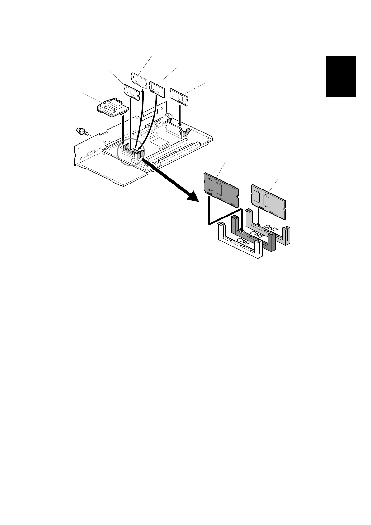
17 January, 2003 OPTIONAL UNIT INSTALLATION
[C]
[A]
[B]
[D]
[E]
Installation
[C]
[B]
G367I205.WMF
G367I701.WMF
2. Replace the printer module [A] in the upper slot with DIMM #1 (SYSTEM) [B].
3. Insert DIMM #2 (PRT/SCN) [C] into the center slot.
4. Insert the 128MB memory [D].
NOTE: 1) It is not necessary to install the additional memory if the present
memory is 192MB or more.
2) Make sure that the modules are firmly set in their slots. If they are
not, this will cause SC997.
5. Attach the NVRAM board [E] (! x 1).
NOTE: 1) It is not necessary to install this NVRAM board in machines that
already contain the optional User Account Enhancement Unit Type
C.
2) If replacing the Unit Type C with the NVRAM board, be sure to back
up and re-enter the User Code data using SmartNetMonitor for
Admin.
1-25
Page 43

OPTIONAL UNIT INSTALLATION 17 January, 2003
[B]
[A]
G367I204.WMF
6. Remove the scanner connector cover [A].
7. Install the IPU board [B] (! x 2).
8. Reinsert the controller into the printer using the 2 screws (M3 x 6) enclosed as
accessories instead of the original screws.
NOTE: Make sure that the IPU board is firmly connected to the controller
board. If it is not, this will cause SC990.
1-26
Page 44

17 January, 2003 OPTIONAL UNIT INSTALLATION
[B]
Installation
[A]
[C]
[I] [H]
[D]
G367I905.WMF
9. Align the cushion [A] as follows and attach it to the backboard [B]:
• Align the top side with the bottom end of the lowermost slot of the right side
stand [C].
• Align the right side with the left side of the right side stand [D].
NOTE: The cushion prevents the right side stand [H] from damaging the
scanner cable [I]. The cushion can be ineffective if attached to an
incorrect position.
G367I903.WMF
1-27
Page 45

OPTIONAL UNIT INSTALLATION 17 January, 2003
[C]
[D]
[A]
[E]
[B]
[G]
[G]
[F]
[F]
G367I105.WMF
[H]
G367I208.WMF
10. Place the pad [A] on the table board [B].
11. Place the scanner unit [C] on the table board so that the scanner unit legs [D]
line up with the indents [E] in the table as shown.
12. Secure the scanner unit in place (! x 2 [F] and spacers [G] enclosed as
accessories for the optional rack).
13. Remove the shipping tape from the scanner cables.
14. Lead the scanner cable [H] along the inside of the rack as shown, then connect
it to the IPU board on the controller frame.
1-28
Page 46

17 January, 2003 OPTIONAL UNIT INSTALLATION
For 120V machines
[A]
Installation
[B]
For 230V machines
G367I602.WMF
[C]
[E]
[D]
G367I601.WMF
15. For 120V machines:
Connect the printer power cord [A] to the output port on the scanner, then plug
the scanner power cord [B] into the power outlet.
For 230V machines:
Connect the power cords [C] from both the printer and scanner to the power
strip [D] enclosed as an accessory. Then, plug the power cord [E] into the
power outlet.
16. Attach the printer main switch cover.
NOTE: Make sure that the wall outlet is near the machine and freely accessible, so
that in the event of an emergency the cord can be easily unplugged.
For 230V machines:
In addition, make sure that the power strip is also freely accessible, so that
in the event of an emergency the power cords from the machines can be
easily unplugged.
1-29
Page 47

OPTIONAL UNIT INSTALLATION 17 January, 2003
17. Select the language in the UP mode.
18. Set the date and time.
19. Enter SP Mode.
20. Clear the scanner application settings by using SP5-801-9.
21. Clear the IPU settings by using SP5-801-12.
22. Exit SP mode and turn the main power off/on.
23. Perform Auto Color Calibration (ACC).
24. Make some test copies in the following modes using a C4 Test Chart.
• Full color in Text Mode
• B&W in Text Mode
25. Check the test copies to make sure each of the following is within standard
values, making any necessary adjustments. (☛ 3.3 Image Adjustment)
• Leading edge registration
• Side-to-side registration
• Scanner sub-scan magnification
• Scanner leading edge registration
• Scanner side-to-side registration
• ARDF side-to-side registration
• ARDF sheet through registration
26. If necessary, perform the touch panel position adjustment. (☛ 3.6 Others )
27. If the customer has a service contract, change the meter charge SP mode
settings accordingly.
1-30
Page 48

17 January, 2003 OPTIONAL UNIT INSTALLATION
1.6.5 INSTALLING THE HANDSET
[D]
[F]
Installation
[C]
[A]
[E]
[B]
G307I114.WMF
NOTE: The optional handset is for the U.S. model only.
1. Remove the thumb screw [A] on the left spacer.
2. Install the handset bracket [B] on the left arm (! x 2, 1 thumb screw).
3. Install the handset holder [C] on the bracket ((! x 2).
4. Place the handset [D] with the handset cord resting on the cord holder [E] of
the bracket.
5. Attach the cord holder [F] (enclosed as accessories for the optional fax unit) to
the uppermost end of the front side of the left side stand.
NOTE: Attached to this position, the cord holder prevents the duplex unit and
the upper left cover from catching the handset cord when they are
closed. The holder can be ineffective if attached to a lower position.
6. Connect the handset cord to the jack.
1-31
Page 49

OPTIONAL UNIT INSTALLATION 17 January, 2003
1.6.6 40GB HDD
Accessories Check List
Description Q'ty
1. 40GB HDD ............................................................................ 1
2. Power Cable ......................................................................... 1
3. Harness................................................................................. 1
4. Screw (M3 x 6)...................................................................... 2
5. Key Top (Document Server) ................................................. 1
40 GB HDD Installation
1. Remove the controller board [A]
((! x 2).
2. Mount the 40GB HDD [B] on the
controller (" x 2, ! x 2).
NOTE: If the CF expander has
already been installed,
remove the IPU board
first, then install the HDD.
3. Reinsert the controller in the
printer using the 2 screws (M3 x
6) enclosed in the CF expander,
instead of the original screws.
NOTE: When installing the HDD
and CF expander
simultaneously, be sure
to install both before
performing the next step.
4. Make sure that the power cords are
properly plugged in, then turn on
the main switch. Format the HDD
according to the instructions
displayed on the touch panel. Print
the configuration page and confirm
that the HDD has been properly
installed.
[B]
[A]
G367I203.WMF
G367I215.WMF
1-32
Page 50

17 January, 2003 OPTIONAL UNIT INSTALLATION
5. Remove the cover key top [A] and
replace it with the document box key
top [B].
[A]
[B]
Installation
G367I218.WMF
1-33
Page 51

OPTIONAL UNIT INSTALLATION 17 January, 2003
1.6.7 ARDF
Accessories Check List
Description Q'ty
1. Stepped Screw ..................................................................... 2
2. Screw (M4 x 10) ................................................................... 2
3. Knob Screw .......................................................................... 4
4. Attention Decal – Scanner.................................................... 1
5. Attention Decal – Top Cover................................................. 1
6. Installation Procedure........................................................... 1
[B]
[C]
[A]
G564I151.WMF
ARDF Installation
1. Attach and tighten [A] (! x 2 stud).
2. Mount the ARDF by aligning the screw keyholes [B] in the ARDF support plate
over the stud screws, and slide the ARDF toward the front of the machine.
NOTE: To avoid damaging the ARDF, hold it as shown in the illustration.
3. Secure the ARDF (! x 2 [C]).
1-34
Page 52

17 January, 2003 OPTIONAL UNIT INSTALLATION
[D]
[A]
[C]
G564I104.WMF
[B]
Installation
[E]
G564I102.WMF
4. Attach the left [A] and right [B] stopper brackets with knob screws [C] (! x 4).
5. Connect the I/F cable [D] (" x 1) to the main machine.
6. Peel off the platen sheet [E] and place it on the exposure glass.
1-35
Page 53

OPTIONAL UNIT INSTALLATION 17 January, 2003
[A]
G564I103.WMF
[D]
[B]
G564I105.WMF
G564I106.WMF
7. Line up the rear left corner of the platen sheet flush against corner [A] on the
exposure glass.
8. Close the ARDF.
9. Attach the decal [B] to the top cover as shown, choosing the language most
suitable for the machine installed.
[C]
10. Attach the decal [C] to the cover so that the arrow on the decal lines up with the
groove [D] of the left scale as shown. As with step 9, choose the language most
suitable for the machine installed.
11. Check the ARDF operation and copy quality. Be sure to check and adjust the
registration for the ARDF with the SP modes.
1-36
Page 54

17 January, 2003 OPTIONAL UNIT INSTALLATION
1.6.8 MULTI-BIN OUTPUT TRAY
Accessories Check List
Description Q'ty
1. Front Tray Holder .................................................................. 1
2. Rear Tray Holder ................................................................... 1
3. Tray ....................................................................................... 2
4. Screw (3 x 1 4) ...................................................................... 4
5. Discharge Brush .................................................................... 2
6. Ground Plate for Left Cover................................................... 1
7. Ground Plate for Upper Exit................................................... 1
8. Ground Plate for Lower Exit................................................... 1
Installing the Multi-Bin Output Tray
NOTE: Before installing the multi-bin output tray, install the duplex unit.
1. Open the left cover [A] of the duplex
[E]
[D]
unit.
2. Install the ground plate [B] behind the
magnet.
3. Install the ground plate [C] on the rear
of the left cover.
4. Attach the ground plate to the top
cover, aligning the bottom edges of
the plate [D] and cover [E].
[C]
[B]
Installation
[A]
G306I101.WMF
5. Attach the discharge brushes [F][G] to
the upper edges of the paper exits, so
that the ends of the brushes [H][I]
touch the ground plates [C][D]
respectively.
NOTE: Make sure the brushes do not
obstruct paper coming from the
exits.
1-37
[H]
[I]
[F]
[G]
G306I102.WMF
Page 55

OPTIONAL UNIT INSTALLATION 17 January, 2003
6. Install the front [A] and rear [B] tray
holders on the top cover (! x 2 for
each).
7. Install the upper [C] and lower [D] trays.
8. Turn the main switch on; select the SP
mode menu, SP6–901–1; and change
the multi-bin output tray setting.
NOTE: The multi-bin output tray is not
automatically recognized by the
printer mainframe. The multi-bin
output tray cannot be used until
you have changed this SP mode
setting.
[A]
[C]
[B]
G306I103.WMF
[D]
1-38
Page 56

17 January, 2003 OPTIONAL UNIT INSTALLATION
1.6.9 ANTI-CONDENSATION HEATER
1. Remove the rear scale [A] (! x 3).
2. Remove the exposure glass [B] with
the left scale [C] (! x 2).
NOTE: You do not have to remove the
ADF exposure glass. If the glass is
removed, position the glass marker
[D] at the rear-left corner when
reattaching.
3. Remove the rear cover [E] (! x 3).
4. Remove the right cover [F] (! x 3).
5. Remove the left cover [G] (! x 3).
6. Remove the rear frame [H] (! x 12, "
x 2).
[C]
[F]
[D]
[B]
[H]
[A]
G367I106.WMF
Installation
7. Install the anti-condensation heater [I]
in the rear-left corner of the scanner
unit (! x 2).
8. Pass the cable through the opening [J]
in the rear rail and connect it to the
connector [K] at the front-left corner of
the power supply unit.
9. Reassemble the scanner unit.
[E]
[K]
[J]
[G]
G367I107.WMF
[I]
G367I219.WMF
1-39
Page 57

17 January, 2003 USER MAINTENANCE
2. PREVENTIVE MAINTENANCE
2.1 USER MAINTENANCE
The following maintenance kits are available for the customer to do PM.
Type A Color (C/M/Y) PCU 50KP
Type B Color (C/M/Y) Development Unit 100KP
Type C Fusing Unit 100KP
Type D Black Development Unit / Dust Filter 100KP
Type E Waste Toner Bottle 50KP
Type F Black PCU 50KP
Type G Oil Supply Unit 30KP
Type H Paper Feed Rollers 150KP
Chart: A4 (LT)/5%
Mode: 5 prints/job
Environment: Normal temperature and humidity
Yield may change depending on circumstances and print conditions.
When the machine’s default settings are used, an error message is displayed when
a maintenance counter reaches the value in the PM table below, except for the
items in maintenance kit H.
NOTE: To have the machine display the message for maintenance kit H also, set
SP5-930-4 to 1.
After the user replaces the items in a maintenance kit, the machine automatically
resets the counter for this maintenance kit, except for the items in kit H.
NOTE: Except for the items in kit H, the machine can automatically detect when
new items have been installed.
The machine stops when the counters for parts in maintenance kits E and G reach
the replacement value in the following table.
NOTE: To have the machine display the alert only for maintenance kits E and G,
set SP5-930-3 to 0.
Preventive
Maintenance
2-1
Page 58

USER MAINTENANCE 17 January, 2003
Symbol key: C: Clean, R: Replace, L: Lubricate, I: Inspect
Main Unit
Item 30K 50K 100K 150K EM Remarks
Black PCU
Color (Y/M/C) PCU
Black Development Unit
Color (C/M/Y) Development Unit
Fusing Unit
Oil Supply Unit
Waste Toner Bottle
Dust Filter
Pick-up Roller
Feed Roller
Separation Roller
R
R
R
R
R
R
R
R
R
R
R
Included in maintenance
kit F
Included in maintenance
kit A
Included in maintenance
kit D
Included in maintenance
kit B
Included in maintenance
kit C
Included in maintenance
kit G
Included in maintenance
kit E
Included in maintenance
kit D
Included in maintenance
kit H
Included in maintenance
kit H
Included in maintenance
kit H
Punch Kit
Item 10K EM Remarks
Chads I Discard chads.
2-2
Page 59

17 January, 2003 SERVICE MAINTENANCE
2.2 SERVICE MAINTENANCE
NOTE: After replacing the transfer unit and the transfer cleaning unit, make sure to
reset the maintenance counter using SP7-804-16 and SP7-804-17
respectively.
After replacing paper feed rollers, reset the maintenance counters for these
also: By-pass tray (7-804-10), Tray 1 (7-804-11), Tray 2 (7-804-12), Tray
3/LCT (7-804-13), Tray 4 (7-804-14)
Symbol key: C: Clean, R: Replace, L: Lubricate, I: Inspect
Main unit
Item 100K 150K 500K 1,000K 3,000K EM Remarks
Transfer Unit R
Transfer Cleaning Unit R
By-pass Feed Roller R
By-pass Pick-up Roller R
By-pass Separation Roller R
Waste Oil Bottle R
One-tray Paper Feed Unit (500 sheets x 1)
Item 100K 150K 500K 1,000K 3,000K EM Remarks
Relay Roller C Damp cloth
Bottom Plate Pad C Damp cloth
Two-tray Paper Feed Unit (500 sheets x 2)
Item 100K 150K 500K 1,000K 3,000K EM Remarks
Relay Roller C Damp cloth
Bottom Plate Pad C Damp cloth
Preventive
Maintenance
LCT (2000 sheets)
Item 100K 150K 500K 1,000K 3,000K EM Remarks
Relay Roller C Damp cloth
Bottom Plate Pad C Damp cloth
Two-tray Finisher
Items 100K 150K 500K 1,000K 3,000K EM Remarks
Rollers C Damp cloth
Discharge Brush C Dry cloth
Sensors C Blower brush
Jogger Fences I Replace if required.
2-3
Page 60

SERVICE MAINTENANCE 17 January, 2003
Four-bin Mailbox
Item 100K 150K 500K 1,000K 3,000K EM Remarks
Rollers C Damp cloth
Tray Paper Sensors
C
Blower blush or dry
cloth
CF Expander
1st Mirror C Optics cloth
2nd Mirror C Optics cloth
3rd Mirror C Optics cloth
APS Sensor C Dry cloth
Xenon Exposure Lamp C Dry cloth
Exposure Glass (Sheet
through)
Item 20k 50k 100k
C
1000k
EM Remarks
Dry cloth or alcohol
ARDF
Item 400k EM Remarks
Pick-up Roller R C
Feed Belt R C
Separation Roller R C
Sensors C C Blower brush
Platen Sheet Cover C
White Plate C Dry or damp cloth
Drive Gear L Grease, G501
Damp cloth or
alcohol
Damp cloth or
alcohol
Damp cloth or
alcohol
Damp cloth or
alcohol. Replace
platen sheet if
required.
NOTE: 400k copies (= 80k originals x 5 copies/original)
2-4
Page 61

17 January, 2003 SPECIAL TOOLS
3. REPLACEMENT AND ADJUSTMENT
!CAUTION
Turn off the main switch and unplug the machine before beginning any of
the procedures in this section.
NOTE: This manual uses the following symbols.
☛ : See or refer to ! : Screw " : Connector
# : Clip ring $ : E ring
3.1 SPECIAL TOOLS
Part Number Part Name Q’ty
N8036701 Flash Memory Card - 4MB 1
G0219350 Loop-back connector - Parallel 1
C4019503 20X Magnification Scope 1
Adjustment
Replacement
3-1
Page 62

IMAGE ADJUSTMENT 17 January, 2003
A
3.2 IMAGE ADJUSTMENT
3.2.1 REGISTRATION
Image Area
The image area shown in the
B
illustration must be guaranteed. So
make sure that the registration is
A
Feed direction
adjusted within the adjustment standard
range as described below.
Image Area
C
= B = C = 4.2mm (1.6”)
G080R902.WMF
Leading Edge
Adjusts the leading edge registration for each paper type and process line speed.
Side to Side
Adjusts the side to side registration for each paper feed station.
NOTE: The side to side registration for the optional paper feed unit, LCT, and
duplex unit can be adjusted with SP mode or with the user tools
(Maintenance menu).
Adjustment Standard
• Leading edge (sub-scan direction): 3 ± 0 mm
• Side to side (main-scan direction): 2 ± 0 mm
Paper Registration Standard
The registration in both main- and sub-scan directions may fluctuate within the
following tolerance.
1st side
• Sub-scan direction: 0 ± 1.5 mm
• Main-scan direction: 0 ± 2 mm
2nd side in duplex
• Sub-scan direction: 0 ± 3 mm
• Main-scan direction: 0 ± 4 mm
3-2
Page 63

17 January, 2003 IMAGE ADJUSTMENT
Adjustment Procedure
1. Enter SP mode and access SP5-997.
2. Print out the pattern (14: 1-dot trimming pattern) with SP5-997.
NOTE: Registration may change slightly print by print as shown above.
Therefore print a few pages of the trimming pattern for step 3 and 4,
and average the leading edge and side-to-side registration values and
adjust each SP mode.
3. Perform the leading edge registration adjustment.
1) Check the leading edge registration and adjust it with SP1-001.
2) Select the adjustment conditions (paper type and process line speed).
3) Input the value then press the [Escape] key.
4) Check the leading edge adjustment by generating the trim pattern.
4. Perform the side to side registration adjustment.
1) Check the side to side registration and adjust it with SP1-002.
2) Select the adjustment conditions (paper feed station).
3) Input the value then press the [Escape] key.
4) Check the side to side adjustment by generating the trim pattern.
Adjustment
Replacement
3.2.2 COLOR REGISTRATION
Line Position Adjustment
Normally, the automatic line position adjustment is executed under a specified
condition to optimize the color prints. If color registration shifts, execute “Auto
Adjust” with the user tools (Maintenance menu – Color registration) or SP5-993-2
to do the forced line position adjustment. In addition, it is recommended to perform
the line position adjustment under the following conditions:
• After transporting or moving the printer (If printers are pre-installed at the
workshop and transported to the user location, forced line position adjustment
should be done after printer installation is completed at the user location.)
• When opening the drum positioning plate
• When removing or replacing the motors, clutches, and/or gears related to the
drum/development/transfer sections
• When removing or replacing the transfer belt or laser optical housing unit
Adjustment of Line Speed for Thick Paper
You must adjust the line speed of the fusing unit (the speed of development motorK) under the following conditions:
• The color registration shifts more on the trailing edge than on the leading
edge.
• This problem has not been solved by the line position adjustment.
Use the following user tool for this adjustment:
• Menu/Maintenance/Color Regist./Fuser Adjust/Thick paper
3-3
Page 64

IMAGE ADJUSTMENT 17 January, 2003
3.2.3 PRINTER GAMMA
NOTE: Normally, the printer gamma is enough to adjust the color balance to
achieve the optimum print output. The gamma correction is only required
Adjustment Overview
Make the gradation scales on the printout smooth from the highlight to the shadow
density. Adjust the CMY gradation scale at the top of the chart by balancing the
density of the C, M, and Y gradation scales – the CMY gray scale should change
smoothly from minimum to maximum, and there should be no coloration.
For each color, you can adjust 15 points between 0 (lowest density) and 255
(highest density).
The gradation scales marked “Default Value” are printed according to the default
gamma settings. The gamma adjustment changes the densities at the adjustable
points in the gradation scale. The gradation scale marked “Current Value” shows
the current settings.
During the adjustment procedure, compare the “Current Value” gradation scale
with the “Default Value” Select the density for each of the 15 adjustable points,
excluding points 0 and 255, from the “Default Value” gradation scale.
for fine-tuning to meet the user requirements.
The NVRAM holds three printer gamma settings, those saved this time (Current),
those saved in the preceding adjustment (Previous), and the factory settings
(Factory).
Adjustment Procedure
1. Enter SP mode.
2. Select “1. Service”
3. Select “Data Recall” and load the settings that will serve as the base for the
adjustment.
4. Select “Mode Selection”, and select the print mode that you are going to adjust.
5. To review the image quality for these settings, choose “Test Page” to print out a
color calibration test sheet.
6. Select “Gamma Adj.”
7. Adjust the color density at each of the 15 points for a color (CMY and K).
8. When the density setting is complete for all colors, print out a color calibration
test sheet again and make sure that the gradation scale for each printed color
is smooth and that the CMY gradation scale is gray. Repeat the adjustment if
there is an anomaly.
9. If the adjustment results prove satisfactory, execute “Data Save.”
3-4
Page 65

17 January, 2003 EXTERIOR COVERS
3.3 EXTERIOR COVERS
3.3.1 REAR COVER AND UPPER REAR COVER
1. Rear cover [A] (! x 4, 2 hooks)
2. Remove the optional mailbox if it is
installed.
3. Upper exit cover [B] (1 hook) if the
optional mailbox is not installed.
4. Open the upper right cover [C].
5. Upper rear cover [D] (! x 4)
3.3.2 PAPER EXIT TRAY
1. Paper exit tray [A] (! x 2)
[C]
[B]
[D]
[A]
G080R903.WMF
Adjustment
Replacement
3.3.3 UPPER RIGHT COVER
1. Right cover [A] (! x 2)
NOTE: To remove the right cover,
open the upper right cover.
2. Upper right cover [B]
[A]
G080R904.WMF
[B]
3-5
[A]
G080R905.WMF
Page 66
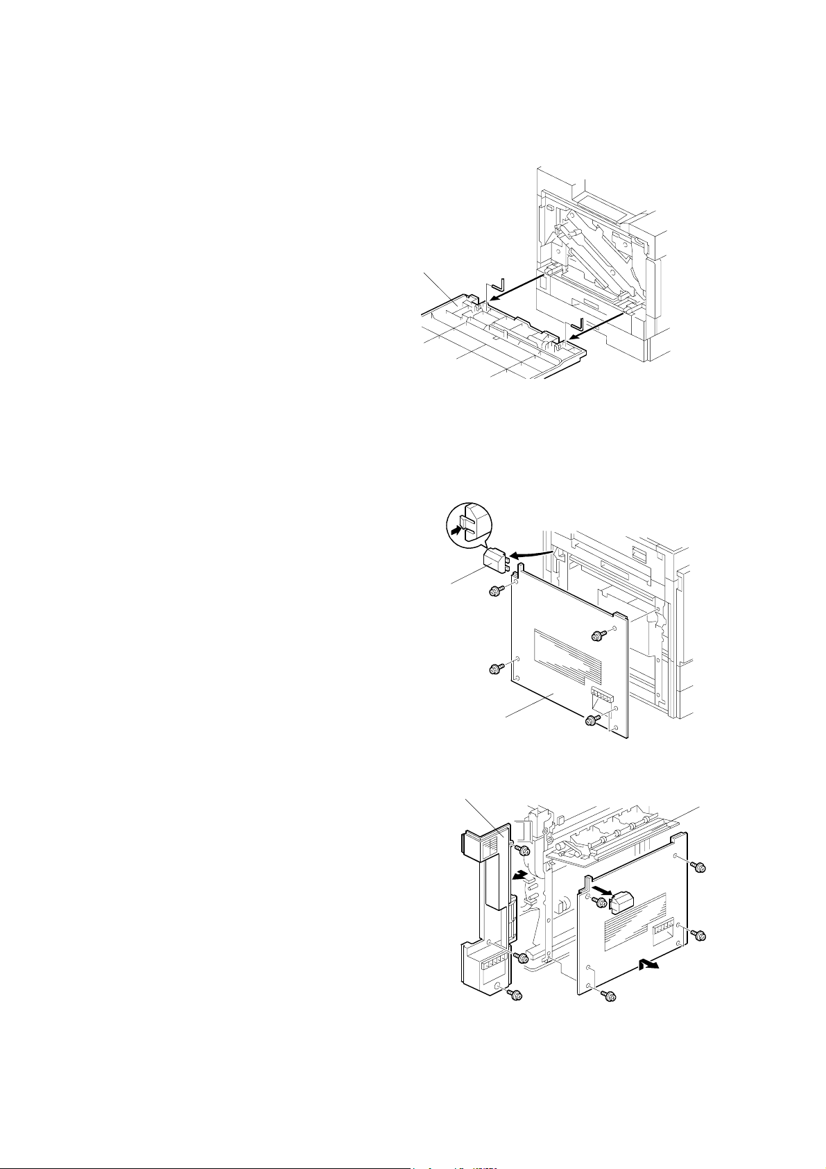
EXTERIOR COVERS 17 January, 2003
3.3.4 FRONT COVER
1. Front cover [A] (2 pins)
[A]
G080R906.WMF
3.3.5 LEFT COVER AND REAR LEFT COVER
1. Remove the optional finisher from the
printer if it is installed.
2. Remove the optional duplex inverter
unit if it is installed.
3. Connector cover [A] if the optional
duplex unit is not installed
4. Left cover [B] (! x 6)
[A]
5. Open the left door [C].
6. Rear left cover [D] (! x 3)
3-6
[D]
[B]
G080R907.WMFFF
[C]
G080R908.WMF
Page 67

17 January, 2003 EXTERIOR COVERS
3.3.6 UPPER LEFT COVER AND OPERATION PANEL
[D]
[C]
[A]
1. Open the front cover [A].
2. Open the upper right cover [B].
3. Operation panel [C] (! x 2, " x 3, 2 hooks)
4. Upper left cover [D] (! x 1, Shoulder-screw x 1, 2 hooks)
G080R909.WMF
[B]
Adjustment
Replacement
3-7
Page 68

LASER OPTICS 17 January, 2003
3.4 LASER OPTICS
!WARNING
Turn off the main switch and unplug the machine before beginning any of
the procedures in this section. Laser beams can cause serious eye injury.
3.4.1 CAUTION DECAL LOCATIONS
Caution decals are placed as shown below.
LASER CAUTION 1.TIF
G080R910.WMF
LASER CAUTION 2.TIF
! WARNING
Be sure to turn off the main switch and disconnect the power plug from the
power outlet before beginning any disassembly or adjustment of the laser
unit. This printer uses a class IIIb laser beam with a wavelength of 655 nm
and an output of 7 mW. The laser can cause serious eye injury.
3-8
Page 69

17 January, 2003 LASER OPTICS
3.4.2 LASER OPTICS HOUSING UNIT
CAUTION: Before installing a new laser optics housing unit, remove the sponge
Steps 1 through 4 refer to the
procedure for a newly supplied unit
that replaces the old one.
padding and the tag from the new unit.
[A]
1. Top cover of the laser optics
housing unit [A] (! x 4)
2. Sponge padding [B]
3. Tag [C]
4. Reinstall the top cover.
5. Rear cover (☛ 3.3)
6. Upper rear cover (☛ 3.3)
7. Paper exit tray (☛ 3.3)
8. Right cover (☛ 3.3)
[C]
[B]
G080R757.WMF
[D]
Replacement
Adjustment
9. Securing screws for the toner
supply unit [D] (! x 4)
10. Securing screws for the laser
optics housing unit [E]
[D]
3-9
[E]
G080R911.WMF
Page 70

LASER OPTICS 17 January, 2003
11. Hold the toner supply unit [C] up
➀. Then, lower the unit ➁.
NOTE: The pin [D] for the front
and rear shafts holds the
toner supply unit.
12. Connector cover [E] (! x 1)
13. Four flat cables [F]
14. Connector [G]
[D]
[F]
[C]
G080R912.WMF
3-10
[G]
[E]
%
G080R913.WMF
Page 71

17 January, 2003 LASER OPTICS
15. Flat cable bracket [G] (! x 1)
16. Cable (clamps [H])
17. Duct [I]
18. Laser optics housing unit (! x 2)
NOTE: Hold the unit with both hands
and slowly lift up.
19. After reinstalling the laser optics
housing unit, do some adjustments (☛
the procedures on the following page).
NOTE: When pulling the laser optics
housing unit up, make sure that the
flat cables from the laser diode
board are not caught by the
brackets. If you roughly remove the
unit without paying attention to this
point, the cables will be caught by
the bracket and the laser diode board may be damaged.
To ensure that the unit is removed carefully, remove the unit by placing a
sheet of paper between the laser optic housing unit and the machine rear
frame, in order to prevent the cables from being caught by the brackets.
[H]
[G]
[I]
G080R914.WMF
G080R209.WMF
Replacement
Adjustment
After installing the laser optics housing unit, do forced line position adjustment
(SP5-993-002 or “Maintenance – Color Registration - Auto Adjust” in User Program
mode).
3-11
Page 72

LASER OPTICS 17 January, 2003
Adjustments after Replacing the Laser Optics Housing Unit
1. Enter SP mode.
2. Input the values printed on three decals on the new laser optics housing unit
into the following SPs. Each decal contains two values.
Value on the left Value on the right Function
Decal 1 SP2-109-3 SP2-109-2 Laser beam pitch
Decal 2 Not used Not used
Decal 3 Not used Not used
Main-scan registration
correction for black and cyan
Main-scan registration
correction for magenta and
yellow
Decal 1
Jp:xxxxx P:46,41
1200dpi600dpi
G080R917.WMF
Decal 2
Jp:xxxxx KC:-2,-2
CK
G080R915.WMF
Decal 3
Jp:xxxxx MY:-2,-2
YM
G080R916.WMF
NOTE: The values on decals 2 and 3 do not need to be input, as the machine
performs the main scan registration correction for each color during
automatic line position adjustment.
3. Print out the following test pattern (17: cross-stitch main-scan) with SP5-997.
4. Check these test patterns. If the laser beam pitch is not correct, vertical black
strips seem to appear.
• Cross-stitch pattern: The thin lines should be of uniform thickness (no
striping effect should appear on the printout).
5. Adjust the laser beam pitch values in SP2-109-2 and -3 until the printout is
correct, as shown below.
Feed direction
Adjustment not completed Adjustment completed
G080R918.WMF
6. Execute SP5-993-2 or “Auto Adjust” with the Maintenance menu in the user
tools.
3-12
Page 73

17 January, 2003 LASER OPTICS
3.4.3 POLYGON MIRROR MOTOR
[A]
[B]
Adjustment
Replacement
G080R919.WMF
1. Laser optics housing unit (☛ 3.4.2)
2. Cover [A] (! x 4)
3. Polygon mirror motor [B] (! x 4, " x 1)
3.4.4 LASER SYNCHRONIZING DETECTOR BOARDS
[A]
1. Laser optics housing unit (☛ 3.4.2)
2. Synchronizing detector boards [A] (! x 1, " x 1)
3-13
G080R920.WMF
Page 74

PCU AND DEVELOPMENT UNIT 17 January, 2003
3.5 PCU AND DEVELOPMENT UNIT
NOTE: Do not touch the PCU development drum. Do not let any metal object
touch the PCU development sleeve.
1. Open the front cover [A].
2. To raise the drum positioning plate [B],
loosen the 2 screws.
3. Turn the release lever [C] counterclockwise.
4. Pull the required development unit [D]
out.
5. Install a new development unit.
6. Check that the development units are
installed in the proper color order
(black → yellow → cyan → magenta
moving from left to right).
NOTE: When the main switch is turned
on, the newly installed
development units are
automatically initialized.
[C]
[A]
[D]
[B]
G080R921.WMF
G080R922.WMF
7. Release the lever and pull the PCU [E]
out until the handle appears.
8. Grasp the handle [F] and pull the PCU
out of the machine.
3-14
[E]
[F]
G080R923.WMF
Page 75

17 January, 2003 PAPER FEED
3.6 PAPER FEED
3.6.1 PICK-UP, FEED, AND SEPARATION ROLLERS
Tray 1 and Tray 2
1. Tray 1 and Tray 2
2. Pick-up roller [A] (1 hook)
3. Feed roller [B] (# x 1)
4. Separation roller [C] (# x 1)
By-pass Tray
1. Open the right door.
2. By-pass tray cover [A] (1 hook, ! x 1)
3. Raise the paper end sensor actuator.
4. Pick-up roller [B] (1 hook)
[A]
[A]
[C]
G080R924.WMF
[B]
[B]
Adjustment
Replacement
5. Feed roller [C] (# x 1)
6. Vertical transport cover [D] (! x 4)
NOTE: Remove the right rear
cover (☛ 3.6.4) if you
want to have easier
access to the four screws.
7. Separation roller [E] (# x 1)
[C]
G080R926.WMF
3-15
G080R925.WMF
[D]
[E]
Page 76

PAPER FEED 17 January, 2003
3.6.2 PAPER WIDTH DETECTION BOARD
[A]
1. Open the by-pass tray.
[D]
[B]
[C]
G080R753.WMF
2. Center the side fences [A].
3. By-pass tray cover [B] (! x 2, 2 hooks)
NOTE: There is a square opening [C] on each side of the tray. Insert a
screwdriver into each of the openings.
4. Paper width detection board [D] (" x 1)
NOTE: To remove the connector,
open the bottom cover [E].
[E]
G080R755.WMF
3-16
Page 77
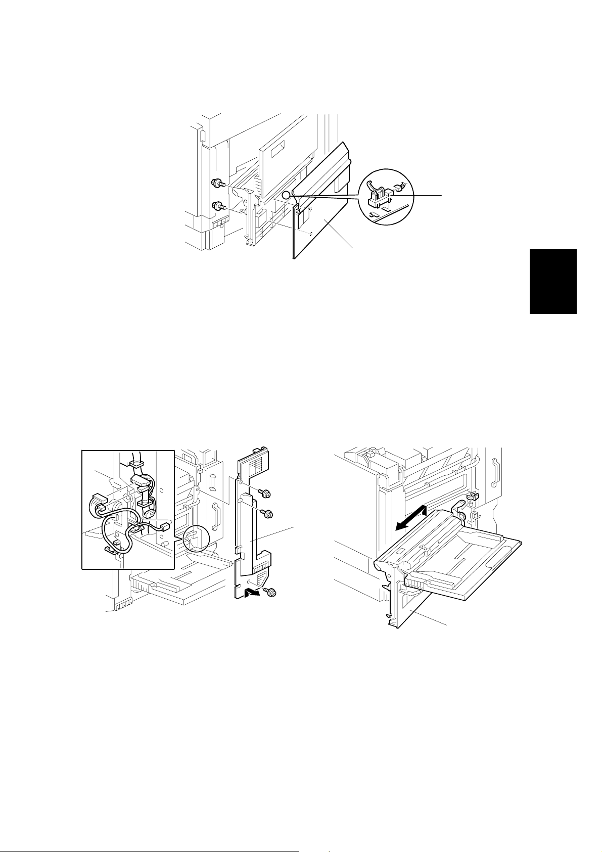
17 January, 2003 PAPER FEED
3.6.3 VERTICAL TRANSPORT SENSOR
[B]
[A]
G080R752.WMF
1. Open the right door.
2. Vertical transport cover [A] (! x 4)
NOTE: Remove the right rear cover (☛ 3.6.4) if you want to have easier
access to the four screws.
Adjustment
Replacement
3. Vertical transport sensor [B] (" x 1)
3.6.4 RIGHT DOOR UNIT
G080R927.WMF
[A]
[B]
G080R928.WMF
1. Rear cover (☛ 3.3)
2. Upper rear cover (☛ 3.3)
3. Upper right cover (☛ 3.3)
4. Right rear cover [A] (! x 4)
5. Open the right door.
6. Lift the vertical transport unit [B] to remove it from its hinges (" x 3, # x 1).
3-17
Page 78

PAPER FEED 17 January, 2003
3.6.5 REGISTRATION SENSOR AND RELAY SENSORS
[B]
[C]
[A]
G080R751.WMF
1. Right door unit (☛ 3.6.4)
2. Registration guide [A] (! x 2)
3. Registration sensor [B] (! x 2, " x 1)
4. Relay sensor [C] (" x 1)
3.6.6 PAPER FEED CLUTCHES
1. Paper trays
2. Rear cover (☛3.3)
3. Swing out the high voltage supply
unit (☛3.10.2).
4. Clutch holder [A] (! x 2, 1 bearing)
G080R929.WMF
[B]
5. Paper feed clutch for tray 1 [B]
(" x 1)
6. Clutch holder [C] (! x 2, 1 bearing)
7. Paper feed clutch for tray 2 [D]
(" x 1)
3-18
[D]
[C]
G080R930.WMF
[A]
Page 79

17 January, 2003 PAPER FEED
3.6.7 BY-PASS FEED CLUTCH
1. Right door unit (☛ 3.6.4)
2. By-pass tray cover [A]
(! x 1, 1 hook)
[A]
3. Loosen the screw on the right
door latch.
4. Turn the latch in the opposite
[C]
direction.
5. Upper guide plate [B] (! x 4)
6. Support plate [C] ($ x 2)
7. Relay gear [D] (1 hook)
8. By-pass feed clutch [E] (" x 1)
3.6.8 TRAY LIFT MOTOR
[E]
[D]
[B]
G080R931.WMF
Replacement
Adjustment
[B]
G080R932.WMF
1. Rear cover (☛ 3.3)
2. Swing out the high voltage supply unit. (☛ 3.10.2)
3. Tray lift motors (tray 1 [A], tray 2 [B]) (! x 2, " x 1)
3-19
[A]
Page 80

PAPER FEED 17 January, 2003
3.6.9 PAPER FEED MOTOR
[B]
[A]
1. Rear cover (☛ 3.3)
2. Swing out the high voltage supply unit. (☛ 3.10.2)
3. Paper feed motor [A] (! x 3, " x 1)
NOTE: The connector is CN604 on the driver board [B].
G080R750.WMF
3-20
Page 81

17 January, 2003 TRANSFER AND PAPER TRANSPORT UNIT
3.7 TRANSFER AND PAPER TRANSPORT UNIT
3.7.1 TRANSFER UNIT
NOTE: 1) When removing or installing the transfer unit, grasp the central areas of
the front and rear frame. Do not touch the transfer belt [A]. Do not
damage the entrance mylar [B].
2) Remove the duplex feed unit (if it is installed) before replacing the
transfer unit.
3) After replacing the transfer unit, reset the maintenance counter, SP7804-16, and conduct the output check, SP5-804-74.
[A]
Adjustment
Replacement
[C]
G080R737.WMF
[B]
1. Turn the release lever counterclockwise. (☛ 3.5)
2. Pull out the transfer unit [C] until the entire unit is visible (! x 2).
3. Grasp the transfer unit grips as shown above. Lift the unit to remove it.
NOTE: Grasp the front grip. Use caution not to damage the actuator on the rear.
After replacing the transfer unit:
• Perform forced line position adjustment (SP5-993-002 or “Maintenance menu –
Color Registration - Auto Adjust” in User Program mode).
• Print the 1-dot grid pattern on A3/11" x 17" paper and check the color shift level
(☛ 4.4.3).
3-21
Page 82

TRANSFER AND PAPER TRANSPORT UNIT 17 January, 2003
3.7.2 TRANSFER BELT CLEANING UNIT
NOTE: After replacing the transfer belt cleaning unit, reset the maintenance
counter, SP7-804-17.
[A]
[B]
G080R739.WMF
While pushing the lever, pull out the transfer belt cleaning unit [A] (! x 1).
NOTE: 1) The blade [B] may damage the belt if you do not keep pushing the lever.
2) When reassembling, check that the transfer unit release lever is put
back to the original position (☛ 3.5).
After replacing the transfer belt cleaning unit, perform forced line position
adjustment (SP5-993-002 or “Maintenance menu – Color registration - Auto Adjust”
in User Program mode).
3-22
Page 83

17 January, 2003 TRANSFER AND PAPER TRANSPORT UNIT
3.7.3 CLEANING BLADE AND CLEANING ROLLER
[A]
[B]
G080R740.WMF
1. Transfer belt cleaning unit (☛ 3.7.2)
Adjustment
Replacement
2. Cleaning blade [A] (! x 2)
3. Tension spring [B]
[D]
[C]
4. Lever [C] (! x 1)
[E]
G080R741.WMF
5. 3 gears [D] ($ x 1)
6. Gear box [E] (! x 1)
3-23
Page 84

TRANSFER AND PAPER TRANSPORT UNIT 17 January, 2003
[A]
[B]
[C]
G080R742.WMF
7. Roller cover [A] (! x 2)
8. Cleaning brush gear [B] ($ x 1)
9. Cleaning brush [C] (Bushing x 1)
After replacing the cleaning blade, perform forced line position adjustment (SP5993-002 or “Maintenance menu – Color registration - Auto Adjust” in User Program
mode).
3-24
Page 85
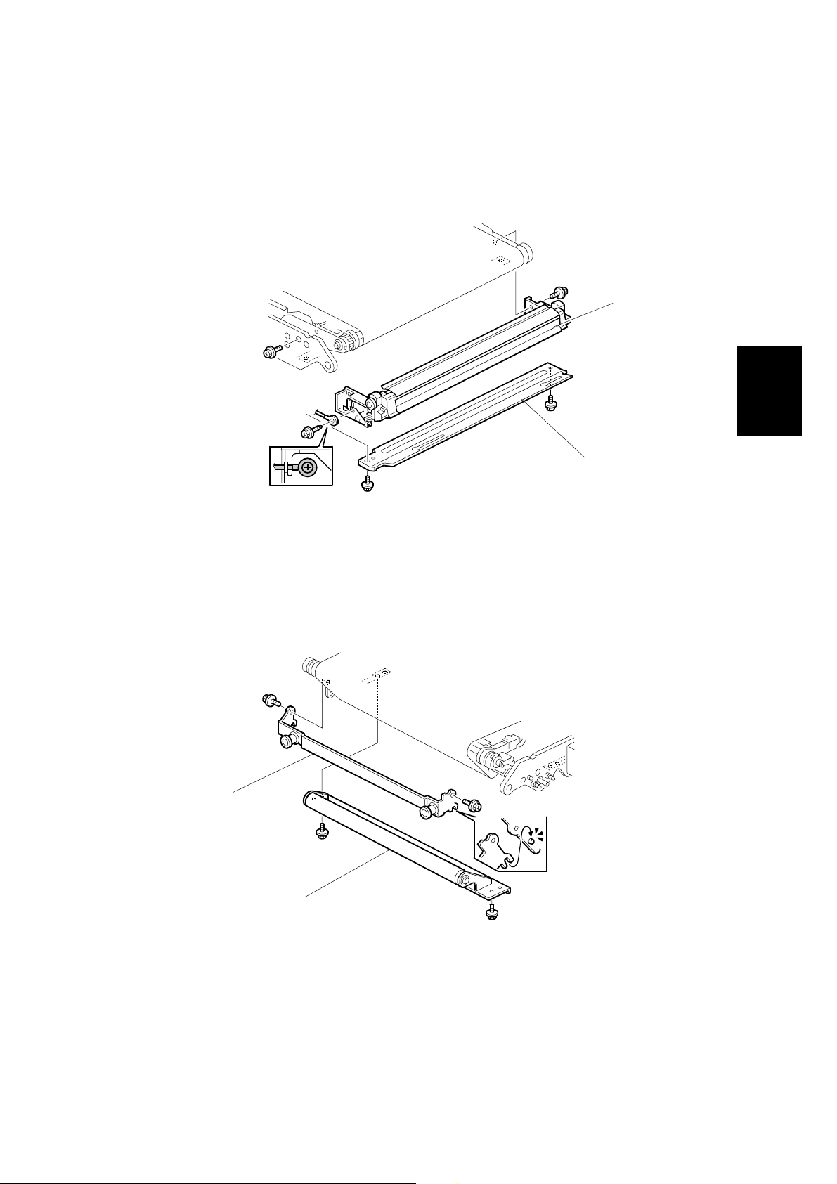
17 January, 2003 TRANSFER AND PAPER TRANSPORT UNIT
3.7.4 TRANSFER BELT
NOTE: Do not touch the transfer belt during handling. When replacing the belt,
hold the belt at its end.
[A]
[B]
Adjustment
Replacement
1. Transfer unit (☛ 3.7.1)
2. Transfer belt cleaning unit (☛ 3.7.2)
3. Transfer entrance guide [A] (! x 3)
4. Right bracket [B] (! x 2)
[C]
G080R744.WMF
[D]
5. Left bracket [C] (! x 2)
6. Tension roller [D] (! x 2)
G080R745.WMF
3-25
Page 86

TRANSFER AND PAPER TRANSPORT UNIT 17 January, 2003
[A]
G080R933.WMF
7. Lay the transfer unit on its side. Grasp the upper end of the transfer belt and
pull the transfer belt [A] up and out.
NOTE: 1) If the transfer charge brushes are dirty, clean them with a vacuum
cleaner.
2) If the drive rollers are dirty, clean them with a damp cloth.
.
After replacing the transfer belt, perform forced line position adjustment (SP5-993002 or “Maintenance menu – Color registration - Auto Adjust” in User Program
mode).
3-26
Page 87
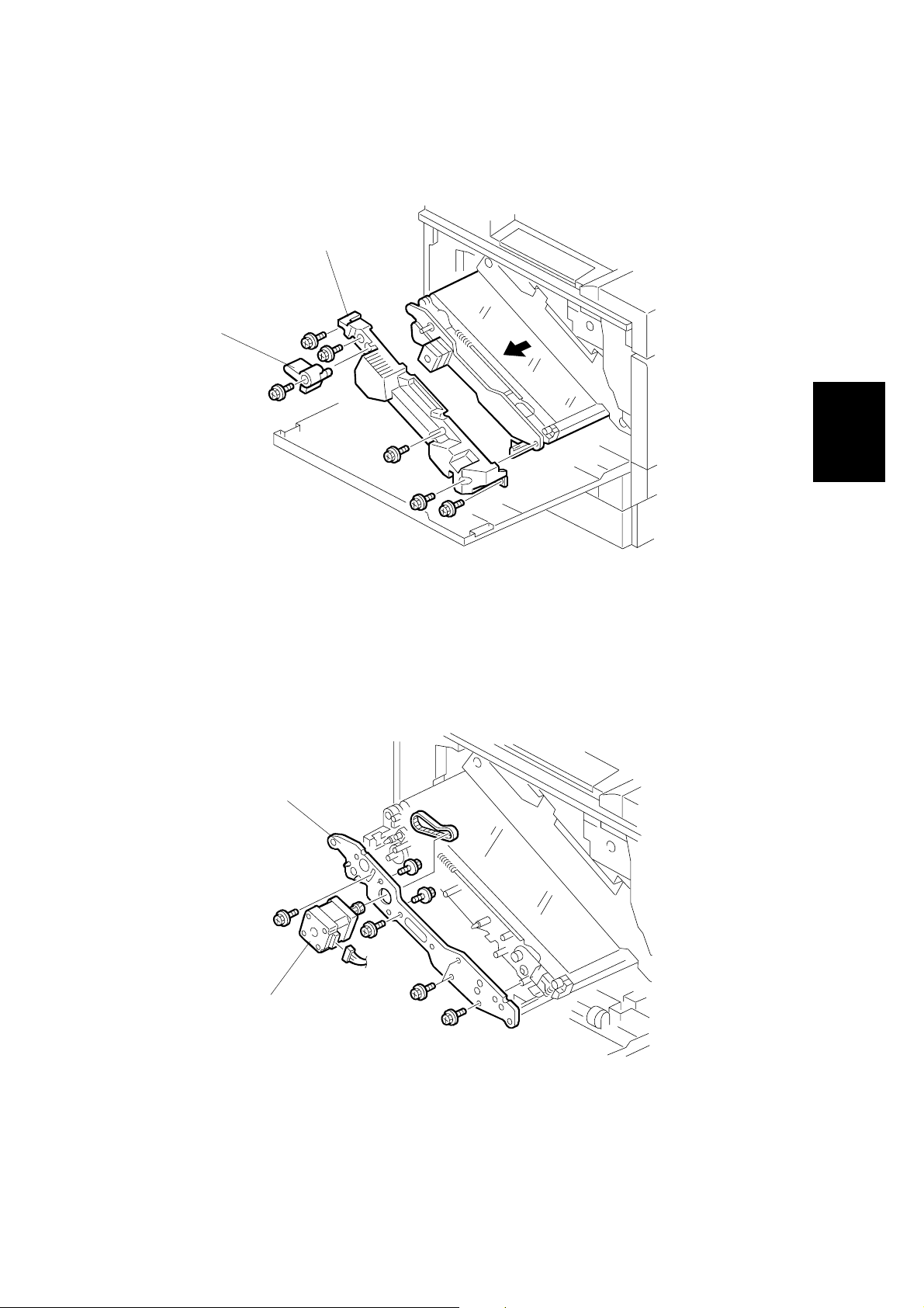
17 January, 2003 TRANSFER AND PAPER TRANSPORT UNIT
3.7.5 TRANSFER UNIT DRIVE MOTOR
[B]
[A]
Adjustment
Replacement
1. Pull out the transfer unit (☛ 3.7.1).
2. Transfer belt cleaning unit (☛ 3.7.2)
3. Release lever [A] (! x 1)
4. Front cover [B] (! x 3)
[C]
[D]
G080R738.WMF
5. Front plate [C] (! x 5, Timing belt x 1)
6. Transfer unit drive motor [D] (! x 2, " x 1)
3-27
G080R743.WMF
Page 88

ID SENSORS 17 January, 2003
3.8 ID SENSORS
[A]
G080R756.WMF
CAUTION: Use caution not to damage the black PCU when removing and
installing the ID sensor bracket.
1. Pull out the transfer unit until the entire unit is visible (☛ 3.7.1).
2. Fusing unit (☛ 3.9.1)
3. ID sensor bracket [A] (! x 2, " x 1)
3-28
Page 89

17 January, 2003 FUSING
3.9 FUSING
!CAUTION
1. Be careful when handling the fusing unit. It is very hot.
2. Take care not to spill silicone oil.
3.9.1 FUSING UNIT
[C]
[B]
[D]
[A]
G080R508.WMF
CAUTION: Do not tilt the fusing unit [A] while handling it. The oil supply unit [B] can
fall off the fusing unit after the grip [C] is released from the oil supply
unit.
Adjustment
Replacement
1. Detach the finisher from the printer if it is installed.
2. Open the duplex inverter unit if it is installed.
3. Push the heat insulator [D]. The grip [C] is released from the oil supply unit.
4. Fusing unit [A]
After replacing the fusing unit, if the customer uses thick paper, make some test
prints on a sample of the paper used by the customer. If there are any color
registration problems, adjust the line speed for thick paper with the following user
tool:
• Menu/Maintenance/Color Regist./Fuser Adjust/Thick paper
Refer to Maintenance Guide of the Operating Instructions for how to adjust this
(section 2. Cleaning and Adjusting the Printer - Adjusting the Color Registration).
3-29
Page 90

FUSING 17 January, 2003
3.9.2 OIL SUPPLY UNIT AND UPPER COVER
[B]
[A]
1. Detach the finisher from the printer if it is installed.
2. Open the duplex inverter unit if it is installed.
3. Fusing unit (☛ 3.9.1)
4. Oil supply unit [A]
5. Upper cover [B] (! x 4)
G080R701.WMF
3-30
Page 91

17 January, 2003 FUSING
3.9.3 CLEANING UNIT
[A]
[B]
[C]
G080R702.WMF
Adjustment
Replacement
1. Upper cover (☛ 3.9.2)
2. 2 handle guides [A][B] (! x 2 for each)
3. Handle [C] (Spring x 1)
[D]
G080R706.WMF
4. Cleaning unit [D] (! x 2)
3-31
Page 92

FUSING 17 January, 2003
3.9.4 HEATING ROLLER LAMP
[C]
[A]
[B]
G080R705.WMF
1. Upper cover (☛ 3.9.2)
2. Heating roller lamp [A] (! x 2)
NOTE: When reinstalling, make sure the front [B] and rear [C] ends of the lamp are
on the correct terminals.
3-32
Page 93

17 January, 2003 FUSING
3.9.5 FUSING BELT UNIT
[A]
[E]
[B]
Adjustment
Replacement
G080R707.WMF
[C]
[D]
1. Cleaning unit (☛ 3.9.3)
2. Heating roller lamp (☛ 3.9.4)
3. Upper paper guide plate (☛ 3.9.8)
4. Pressure roller gear [A] (C ring x 1)
5. 2 pressure brackets [B][C] (Spring x 1 for each)
6. Knob [D] (! x 1)
7. Fusing belt unit [E] (! x 1, " x 1)
3-33
Page 94

FUSING 17 January, 2003
3.9.6 HOT ROLLER
[A]
G080R708.WMF
1. Fusing belt unit (☛ 3.9.5)
2. Hot roller [A] (Bushing x 2)
3.9.7 HEATING ROLLER
[A]
G080R709.WMF
1. Pressure roller (☛ 3.9.6)
2. Heating roller [A]
3-34
Page 95

17 January, 2003 FUSING
3.9.8 PAPER GUIDE PLATES AND STRIPPER PAWLS
[A]
Adjustment
Replacement
1. Upper cover (☛ 3.9.2)
2. Lower paper guide plate [A] (! x 2)
[B]
[C]
G080R703.WMF
G080R704.WMF
3. Upper paper guide plate [B] (! x 2)
4. 5 stripper pawls [C]
3-35
Page 96

FUSING 17 January, 2003
3.9.9 THERMISTOR AND FUSE
[A]
G080R713.WMF
1. Lower right cover [A] (! x 2)
2. Thermistor [B] (! x 1, " x 1)
[B]
G080R714.WMF
3-36
Page 97

17 January, 2003 FUSING
[A]
3. Fuse [A] (! x 3)
3.9.10 PRESSURE ROLLER FUSING LAMP
[A]
G080R715.WMF
Adjustment
Replacement
1. Fusing belt unit (☛ 3.9.5)
2. Pressure roller fusing lamp [A] (! x 2)
3-37
G080R710.WMF
Page 98

FUSING 17 January, 2003
3.9.11 PRESSURE ROLLER
[C]
[A]
G080R711.W MF
1. Pressure roller fusing lamp (☛ 3.9.10)
2. Lower paper guide plate (☛ 3.9.8)
3. Drive gear holder [A] (! x 1)
4. Drive gear [B] ($ x 1)
5. Lower right cover (☛ 3.9.9)
6. Pressure roller unit [C] (! x 5, " x 2)
[B]
3-38
Page 99

17 January, 2003 FUSING
[C]
[A]
Adjustment
Replacement
G080R712.WMF
7. Pressure roller gear [A] (C ring x 1, Bushing x 1)
8. Pressure roller holder [B] (! x 1)
9. Pressure roller [C] (C ring x 1)
[B]
3-39
Page 100
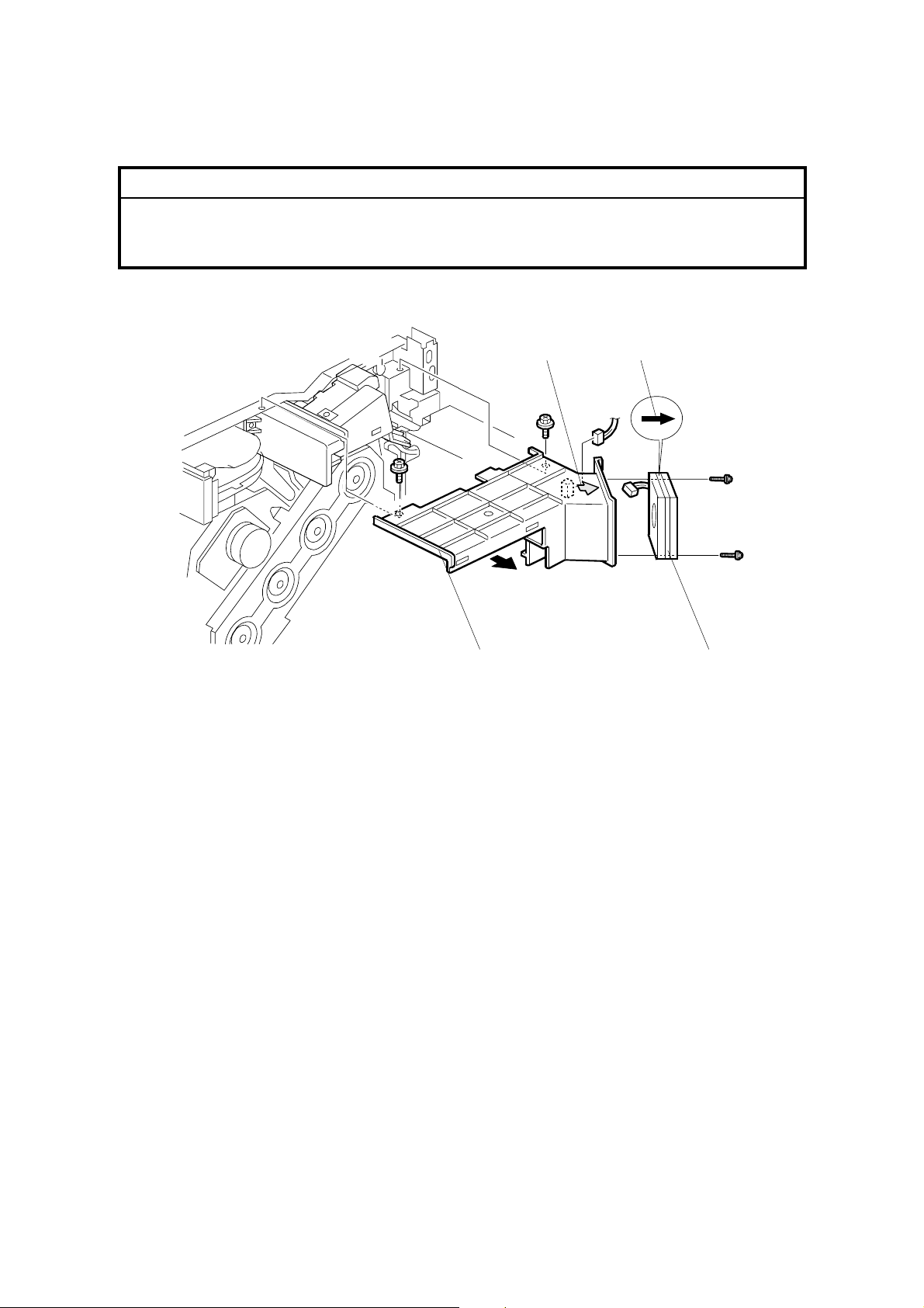
FUSING 17 January, 2003
3.9.12 FUSING UNIT FAN
!CAUTION
When reinstalling, make sure the fan faces to the correct direction. The
arrow on the fan [A] and the arrow on the duct [B] must face to the same
direction.
[A] [B]
1. Rear cover (☛ 3.3)
2. Upper rear cover (☛ 3.3)
3. Left cover (☛ 3.3)
4. Rear left cover (☛ 3.3)
5. Connector cover (on the top of the controller box) (☛3.10.1)
6. Fusing fan duct [C] (! x 2, " x 1)
7. Fusing fan [D] (! x 2, " x 1)
[D] [C]
G080R901.WMF
3-40
 Loading...