

Page 1
Guide to Printer Parts
Setting Up
Preparing to Print
Installing Options
Setup Guide
For safe and correct use of this machine, please be sure to read the Safety Information in the
Setup Guide b efore you us e it.
Page 2

Introduction
This manual describes detailed instructions on the operation and notes about the use of this machine.
To get maximum versatility from this machine all operators are requested to read this manual carefully
and follow the instructions. Please keep this manual in a handy place near the machine.
Power Source
220 - 240 V, 50/60 Hz, 6 A or more
Please be sure to connect the power cable to a power source as above.
Operator Safety:
This printer is considered a class 1 laser device, safe for office/EDP use. The printer contains 7 milliwat,
645 - 660 nanometer wavelength, AlGaInp Laser Diode. Direct (or indirect reflected) eye contact with
the laser beam might cause serious eye damage. Safety precautions and interlock mechanisms have
been designed to prevent any possible laser beam exposure to the operator.
The following label is attached on the back of the printer.
Laser Safety:
The optical housing unit can only be repaired in a factory or at a location with the requisite equipment.
The laser subsystem is replaceable in the field by a qualified Customer Engineer. The laser chassis is
not repairable in the field. Customer engineers are therefore directed to return all chassis and laser subsystems to the factory or service depot when replacement of the optical subsystem is required.
Important
Contents of this manual are subject to change without prior notice. In no event will the company be liable for direct, indirect, special, incidental, or consequential damages as a result of handling or operating the machine.
Caution:
Use of controls or adjustment or performance of procedures other than those specified in this manual
might result in hazardous radiation exposure.
Do not attempt any maintenance or troubleshooting other than that mentioned in this manual. This
printer contains a laser beam generator and direct exposure to laser beams can cause permanent eye
damage.
Two kinds of size notation are employed in this manual. With this machine refer to the metric version.
For good copy quality, the supplier recommends that you use genuine toner from the supplier.
The supplier shall not be responsible for any damage or expense that might result from the use of parts
other than genuine parts from the supplier with your office products.
Page 3

Trademarks
Microsoft, Windows, and Windows NT are registered trademarks of Microsoft
Corporation in the United States and/or other countries.
IPS-PRINT Printer Language Emulation Copyright© 1999-2000 Oak Technology, Inc., All rights reserved.
Ethernet is a registered trademark of Xerox Corporation.
Bluetooth is a Trademark of the Bluetooth SIG, Inc. (Special Interest Group) and
licensed to RICOH Company Limited.
Copyright© 2001 Bluetooth SIG, Inc.
The Bluetooth Trademarks are owned by Bluetooth SIG, Inc. USA
Other product names used herein are for identification purposes only and might
be trademarks of their respective companies. We disclaim any and all rights involved with those marks.
Notes:
Some illustrations in this manual might be slightly different from the machine.
Certain options might not be available in some countries. For details, please contact your sales or service representative.
Note
The proper names of the Windows operating systems are as follows:
• The product name of Windows
• The product name of Windows
• The product name of Windows
Edition (Windows Me).
• The product names of Windows
Microsoft
Microsoft
Microsoft
• The product names of Windows
Microsoft
Microsoft
• The product names of Windows NT
Microsoft
Microsoft
®
Windows® 2000 Advanced Server
®
Windows® 2000 Server
®
Windows® 2000 Professional
®
Windows® XP Professional
®
Windows® XP Home Edition
®
Windows NT® Server 4.0
®
Windows NT® Workstation 4.0
®
95 is Microsoft® Windows® 95.
®
98 is Microsoft® Windows® 98.
®
Me is Microsoft® Windows® Millennium
®
2000 are as follows:
®
XP are as follows:
®
4.0 are as follows:
i
Page 4

Safety Information
R
R
When using your equipment, the following safety precautions should always be
followed.
Safety During Operation
In this manual, the following important symbols are used:
WARNING:
CAUTION:
Ignoring this warning could cause serious injury or even death.
Ignoring this caution could cause injury or damage to property.
ii
Page 5

R WARNING:
• Only connected the machine to the power source described on the inside front cover of this manual.
• Avoid multi-wiring.
•
Do not damage, break or make any modifications to the power cord.
Do not place heavy objects on it, pull it hard or bend it more than necessary. These actions could cause an electric shock or fire.
•
Do not plug or unplug the power cord with your hands wet. Otherwise,
an electric shock might occur.
• Make sure the wall outlet is near the machine and freely accessible so
that in event of an emergency it can be unplugged easily.
• Do not remove any covers or screws other than those specified in this
manual. Some parts of the machine are at a high voltage and could
give you an electric shock. Also, if the machine has laser systems, direct (or indirect) reflected eye contact with the laser beam may cause
serious eye damage. When the machine needs to be checked, adjusted, or repaired, contact your service representative.
• Do not take apart or attempt any modifications to this machine. There
is a risk of fire, electric shock, explosion or loss of sight. If the machine
has laser system, there is a risk of serious eye damage.
• If the machine looks damaged or breaks down, smoke is coming out,
there is a strange smell or anything looks unusual, immediately turn
off the operation and main power switches then unplug the power cord
from the wall. Do not continue using the machine in this condition.
Contact your service representative.
• If metal, liquid or foreign matter falls into the machine, turn off the operation and main power switches, and unplug the main power cord.
Contact your service representative. Do not keep using the machine
with a fault or defect.
• Do not put any metal objects or containers holding water (e.g. vases,
flowerpots, glasses) on the machine. If the contents fall inside the machine, a fire or electric shock could occur.
• Do not incinerate used toner or toner containers. Toner dust might ignite when exposed to an open flame. Dispose of the used toner containers according to local regulations for plastics.
•
Confirm that the wall outlet is near the machine and freely accessible,
so that in event of an emergency, it can be unplugged easily.
•
To avoid hazardous electric shock or laser radiation exposure, do not
remove any covers or screws other than those specified in this manual.
iii
Page 6

R CAUTION:
• Keep the machine away from humidity and dust. A fire or an electric shock
might occur.
• Do not place the machine on an unstable or tilted surface. If it topples over,
it could cause injury.
• After you move the machine, fix it with the caster fixture. Otherwise, the machine might move or come down to cause a personal injury.
• When you move the machine, unplug the power code from the wall outlet to
avoid fire or electric shock.
• When machine will not be used for a long time, unplug the power code.
• When you pull out the plug from the socket, grip the plug to avoid damaging
the cord and causing fire or electric shock.
• If you use the machine in a confined space, make sure there is a continuous
air turnover.
• Do not reuse stapled paper. Do not use aluminum foil, carbon-containing
paper or other conductive paper. Otherwise, a fire might occur.
• When removing misfed paper, do not touch the fusing section because it
could be very hot.
• This machine has been tested for safety using this suppliers parts and consumables. We recommend you only use these specified supplies.
• Touch only the handles, no other parts. The fuser oil unit gets very hot and
will burn your hands if you touch it.
• Do not eat or swallow toner.
• Keep toner (used or unused) and toner containers out of reach of children.
• Deliver to collection point for waste products. Do not be disposed of via do-
mestic refuse collection.
• The inside of the machine becomes very hot. Do not touch the parts with a
label indicating a “hot surface”. Touching a “hot surface” could result in a
burn (v: means “hot surface”).
• The User Account Enhance Unit installed on the controller has a IC2 lithium
battery which can explode if replaced incorrectly. Replace the User Account
Enhance Unit only with the indicated one.
• Do not place the IC2 lithium battery near or into fire, or it will explode and
cause a burn.
• Keep the fuser oil unit away from flames. There is a risk of fire or burns.
• Keep the waste oil bottle away from flames. There is a risk of fire or burns.
iv
Page 7

Note
❒ Disposal should take place at an authorized dealer or an appropriate collec-
tion site. An IC2 lithium battery is inside the User Account Enhance Unit.
❒ If you are disposing the User Account Enhance Unit, separate the IC2 lithium
battery from the board and dispose of them according to local regulations.
❒ To avoid possible build-up of ozone, locate this machine in a large well ven-
tilated room that has an air turnover of more than 30 m
3
/hr/person.
❒ When you use this machine for a long time in a confined space without good
ventilation, you may notice an odd smell. To keep the workplace comfortable,
we recommend that you keep it well ventilated.
Important
❒ Rating voltage of the connector for options: Max. DC 24 V.
v
Page 8
ENERGY STAR Program
As an ENERGY STAR Partner, we have determined
that this machine model meets the ENERGY STAR
Guidelines for energy efficiency.
The ENERGY STAR Guidelines intend to establish an international energy-saving system for
developing and introducing energy-efficient office equipment to deal with environmental issues, such as global warming.
When a product meets the ENERGY STAR Guidelines for energy efficiency, the Partner shall
place the ENERGY STAR logo onto the machine model.
This product was designed to reduce the environmental impact associated with office equipment by means of energy-saving features, such as Low-power mode.
❖❖❖❖ Low-power Mode (Energy Saver mode)
This printer automatically lowers its power consumption 60 minutes after the
last operation has been completed. To exit Low-power (Energy Saver) mode,
press any key on the control panel. For details about how to configure Energy
Saver mode, see “Making Printer Settings using the Control Panel”, Adminis-
trator Reference as a PDF file on the CD-ROM.
❖❖❖❖ Specifications
Energy Saver mode Power Consumption 15 W or less
Default Time 60 minutes
Recovery Time 99 seconds or less
vi
Page 9

How to Read This Manual
R
R
Symbols
In this manual, the following symbols are used:
WARNING:
This symbol indicates a potentially hazardous situation which, if instructions
are not followed, could result in death or serious injury.
CAUTION:
This symbol indicates a potentially hazardous situation which, if instructions
are not followed, may result in minor or moderate injury or damage to property.
* The statements above are notes for your safety.
Important
If this instruction is not followed, paper might be misfed, or data might be lost.
Be sure to read this.
Preparation
This symbol indicates the prior knowledge or preparations required before operating.
Note
This symbol indicates precautions for operation, or actions to take after misoperation.
Limitation
This symbol indicates numerical limits, functions that cannot be used together,
or conditions in which a particular function cannot be used.
Reference
This symbol indicates a reference.
[]
Keys that appear on the machine's display.
Keys and buttons that appear on the computer's display.
{}
Keys built into the machine's control panel.
Keys on the computer's keyboard.
vii
Page 10

TABLE OF CONTENTS
Trademarks..............................................................................................................i
Safety Information .................................................................................................ii
Safety During Operation............................................................................................. ii
ENERGY STAR Program......................................................................................vi
How to Read This Manual ...................................................................................vii
1. Guide to Printer Parts
Exterior: Front View...............................................................................................1
Exterior: Rear View ................................................................................................3
Interior.....................................................................................................................4
Control Panel..........................................................................................................5
2. Setting Up
Where to Put the Printer........................................................................................7
Checking the Contents of the Box.....................................................................10
Unpacking.............................................................................................................12
Installing the Fuser Oil Unit................................................................................15
Installing the Toner Cartridge............................................................................. 17
Loading Paper......................................................................................................19
Loading Paper in Tray 1...........................................................................................19
Loading Paper in Tray 2 and the Optional Paper Feed Unit ....................................19
2000-sheet Large Capacity Tray..............................................................................21
Turning the Power On .........................................................................................22
Selecting the Display Language.........................................................................23
Test Printing.........................................................................................................24
3. Preparing to Print
Connecting the Printer ........................................................................................25
Connecting to a Network..........................................................................................25
Parallel Connection..................................................................................................26
Configuring the Printer for the Network using the Control Panel ..................27
Installing the Printer Driver.................................................................................30
viii
Page 11

4. Installing Options
Installing Options.................................................................................................33
Using the Screwdriver .........................................................................................37
Paper Feed Unit....................................................................................................38
Installing the Paper Feed Unit Type 3800C (500 × 1) ..............................................38
Installing the Paper Feed Unit Type 3800C (500 × 2) ..............................................41
Installing the Paper Bank PS470 (2000-sheet Large Capacity Tray).......................43
Memory Unit TypeC (SDRAM Module) ...............................................................46
1394 Interface Unit Type 4510.............................................................................48
Connecting the Cable to the 1394 Interface Unit .....................................................50
IEEE 1394 Configuration..........................................................................................51
USB 2.0 Interface Board Type A ......................................................................... 54
Connecting the Cable to the USB 2.0 Interface Board.............................................56
802.11b Interface Unit Type A ............................................................................. 57
IEEE 802.11b (wireless LAN) Configuration ............................................................59
Bluetooth Unit Type 2045 .................................................................................... 63
User Account Enhance Unit TypeC....................................................................66
Printer Hard Disk Type 7000 ............................................................................... 69
Formatting the Printer Hard Disk Drive ....................................................................72
Duplex Unit Type 7000.........................................................................................73
Installing the Duplex Reversal Unit Stand................................................................73
Installing the Duplex Reversal Unit ..........................................................................76
Installing the Duplex Feed Unit ................................................................................78
SR770 (2 Tray Finisher).......................................................................................80
Mail Bin Type 3800C (4-bin Mailbox)..................................................................87
INDEX......................................................................................................... 91
ix
Page 12

x
Page 13
1. Guide to Printer Parts
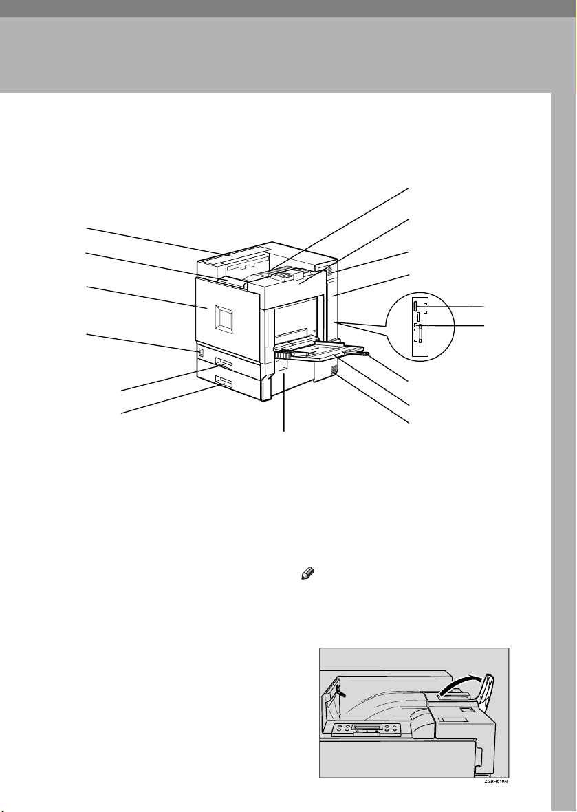
Exterior: Front View
7
1
2
3
4
5
6
1.
Upper cover
Remove to install the optional 4-bin mailbox.
2.
Control panel
Contains keys for printer operation and a
display to show printer status.
See p.5 “Control Panel”.
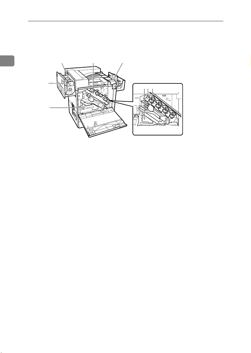
3.
Front cover
Open this when replacing the waste toner
bottle, development unit or photoconductor unit. A screwdriver is attached to
this cover.
4.
Power switch
Use this to switch between power on and
off.
5.
Tray 1
Loads up to 500 sheets of plain paper tray
for printing. Only for A4 K paper.
8
9
10
13
14
15
16
6.
Tray 2
Loads up to 500 sheets of plain paper tray
for printing.
7.
Standard tray
Output is stacked here with the print side
down.
Note
❒ If printed A3 short-edge feed or 11×17
short-edge feed sheets fall off the
standard tray, raise the fence to secure
them.
11
12
1
Page 14

Guide to Printer Parts
8.
Upper right cover
Open this to replace the toner cartridge.
9.
Vent
This helps keep internal components
1
from overheating. Do not block or obstruct the vent. Malfunctions may occur
due to overheating.
10.
Controller board
Slide this out to install options such as the
memory unit, 1394 interface unit, USB interface board, 802.11b interface unit, user
account enhance unit or printer hard
disk.
Plug cables such as the parallel interface
cable and Ethernet cable into their connectors.
11.
Parallel port
Use a parallel cable to connect the printer
to the host computer.
12.
Ethernet port
Use a network interface cable to connect
the printer to a network.
13.
Bypass tray extension
Pull this out to load paper in the bypass
tray when its length is longer than A4 L.
14.
Bypass tray
Use to print on thick paper, OHP transparencies, custom size paper, and plain
paper. Up to 100 sheets of plain paper can
be loaded.
15.
Vent
This helps keep internal components
from overheating. Do not block or obstruct the vent. Malfunctions may occur
due to overheating.
16.
Right cover
Open this to remove misfed paper.
2
Page 15
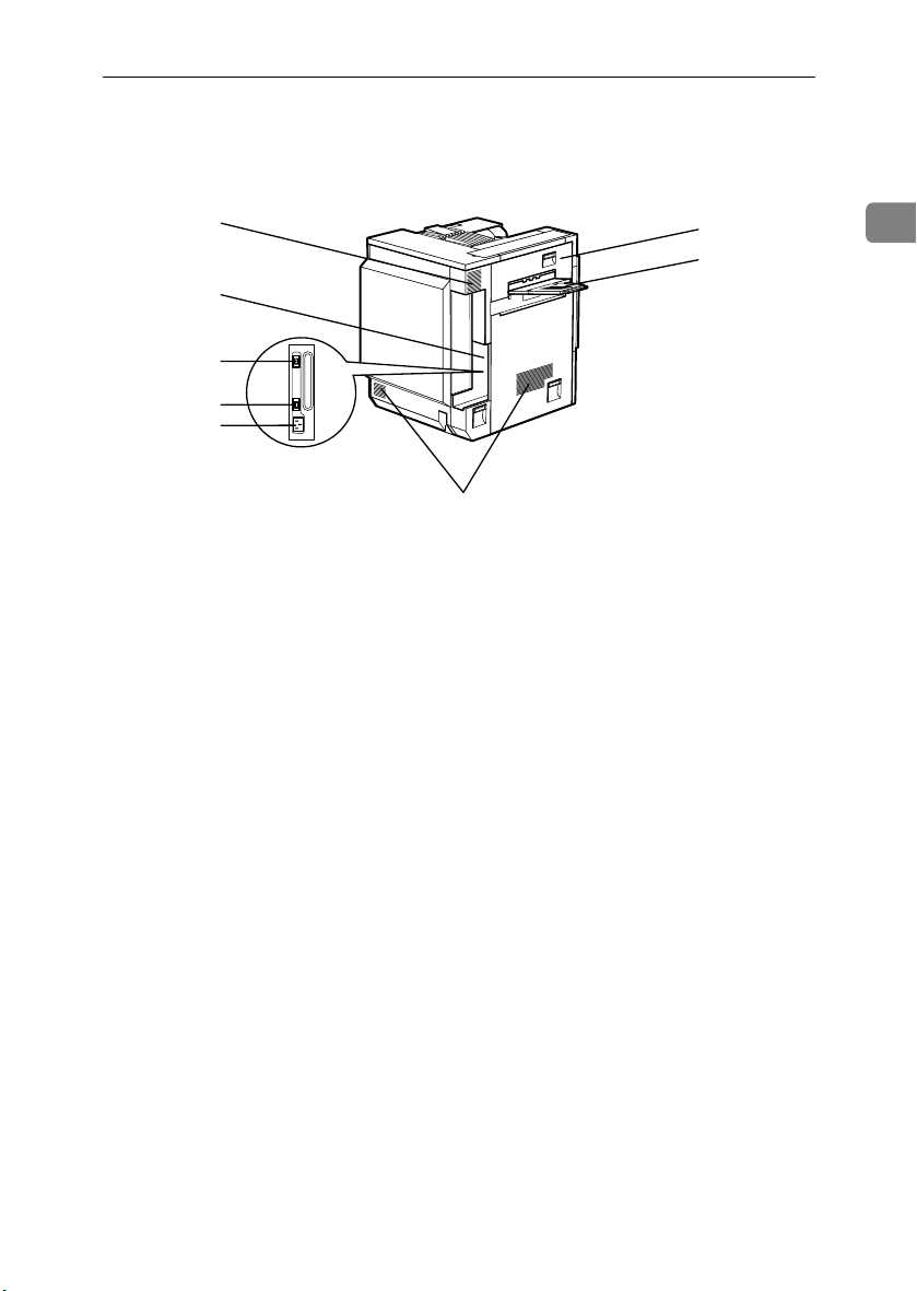
Exterior: Rear View
Exterior: Rear View
1
2
3
4
5
1.
Vent and dustproof filter
This helps keep internal components
from overheating. Do not block or obstruct the vent. Malfunctions may occur
due to overheating. Remove the vent to
replace the internal dustproof filter.
2.
Connector board
Connect the main power cable, cables
from options, etc. to the appropriate port.
3.
Duplex unit port
Connect the cable for the duplex reversal
unit to this port.
4.
4-bin mailbox / 2 tray finisher port
Connect the cable for the 4-bin mailbox or
the 2 tray finisher to this port.
6
7
8
5.
Power port
Connect the power cable to this port and
the other end to the wall outlet.
6.
Upper left cover
Open this to remove misfed paper or
when replacing the fusing unit.
7.
External tray
Printed output is stacked here with the
print side up.
8.
Vents
These help keep components inside the
printer from overheating. Do not block or
obstruct the vents. Malfunctions may occur due to overheating.
ZHXH830N
1
3
Page 16
Guide to Printer Parts
Interior
1
1.
Fusing unit
Fuses the image onto the paper.
2.
Fuser oil unit
Attaches to the fusing unit.
3.
Waste toner bottle
Collects toner that is wasted during
printing.
4.
Inner cover
Open this when replacing the photoconductor unit or development unit.
5.
Photoconductor unit
The printer comes with one black and
three color (yellow, cyan, and magenta)
photoconductor units.
2
1
8
47
6.
Development unit
The printer comes with one black development unit and three color (yellow, cyan, magenta) development units.
7.
Toner cartridge
Loads from the printer rear, in the order
of magenta (M), cyan (C), yellow (Y), and
black (K).
8.
Waste oil bottle
Collects oil discharged during printing.
653
ZHXH840J
4
Page 17
Control Panel
Control Panel
1
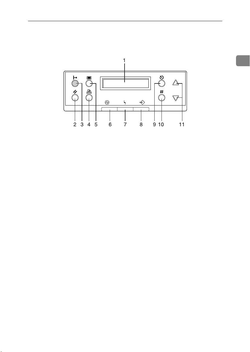
1.
Display
Displays current printer status and error
messages.
2.
{{{{Job Reset}}}} key
When the printer is online, press this key
to cancel an ongoing print job.
3.
{{{{On Line}}}} key
Indicates whether the printer is online or
offline.
Press this to switch between online and
offline.
When the lamp is lit, the printer is online,
enabling data reception from the host
computer.
When the lamp is unlit, the printer is offline, disabling data reception from the
host computer.
Press to return to the ready condition.
4.
{{{{Form Feed}}}} key
When the printer is offline, press this to
print all data left in the printer's input
buffer.
You can use this to force the printer to
print data received in the online status
when the paper size or type does not
match the actually set size or type.
5.
{{{{Menu}}}} key
Press this to make and check current
printer settings.
6.
Power indicator
This indicator remains lit while the power is on. It is unlit when the power is off
or while the printer is in Energy Saver
mode.
7.
Error indicator
Lights up whenever a printer error occurs. However, it is unlit in Energy Saver
mode.
8.
Data In indicator
Blinks when the printer is receiving data
from a computer. The Data In indicator is
lit if there is data to be printed.
9.
{{{{Escape}}}} key
Press this to return to the previous display screen.
10.
{{{{Enter #}}}} key
Press this to execute menu items selected
on the display.
11.
{{{{UUUU}}}}, {{{{TTTT}}}} Keys
Use these to increase or decrease values
on the display when making settings.
Keep the key pressed to quicken scrolling, and increase or decrease values on
the display in units of 10.
5
Page 18

Guide to Printer Parts
1
6
Page 19
2. Setting Up
R
R
Where to Put the Printer
The printer's location should be carefully chosen because environmental conditions greatly affect its performance.
WARNING:
•
Confirm the wall outlet is near the machine and freely accessible,
so that in the event of emergency, it can be easily unplugged.
• Only connect the machine to the power source described on this
sheet.
•
Avoid multi-wiring.
•
Do not damage, break or make any modifications to the power cable. Do not place heavy objects on it, pull it hard or bend it more
than necessary. These actions could damage the cable. A frayed or
damaged cable might cause an electrical fire hazard.
CAUTION:
• Do not handle the plug with wet hands. Doing so might cause an electri-
cal shock.
• Keep the machine in an area that is within optimum environmental con-
ditions. Operating the machine in an environment that is outside the recommended ranges of humidity and temperature can cause an electrical
fire hazard. Keep the area around the socket free of dust. Accumulated
dust can become an electrical fire hazard.
• Place the machine on a strong and level surface. Otherwise, it might fall
and injure someone.
• If you use the machine in a confined space, ensure there is continuous
air circulation.
7
Page 20
Setting Up
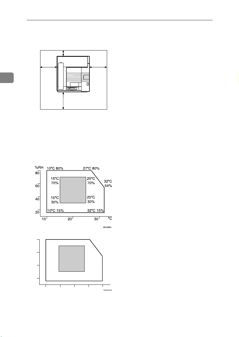
❖❖❖❖ Space Required for Installation
Leave enough space around the printer. This space is necessary to operate the
printer. The recommended (or minimum) space requirements are as follows:
B
A
C
2
D
ZDJX005J
A: 46 cm (19 inch) or more
B: 10 cm (4 inch) or more
C: 55 cm (22 inch) or more
D: 70 cm (28 inch) or more
❖❖❖❖ Optimum Environmental Conditions
Permissible and recommended temperature and humidity ranges are as follows:
%RH
50°F 80%
80
59°F
70%
60
40
59°F
30%
50°F 15%
20
50 80 90
60 70
80.6°F 80%
77°F
70%
77°F
30%
89.6°F 15%
89.6°F
54%
°F
• White area: Permissible Range
• Gray area: Recommended Range
8
Page 21

Where to Put the Printer
Note
❒ The machine must be level within 5 mm, 0.2” from both front to rear and
left to right.
❒ To avoid possible build-up of ozone, locate this machine in a large well
ventilated room that has an air turnover of more than 30 m
❒ When you use this machine for a long time in a confined space without
good ventilation, you may detect an odd smell. To keep the workplace
comfortable, we recommend you keep it well ventilated.
3
/hr/person.
❖❖❖❖ Environments to Avoid
Important
❒ Areas exposed to direct sunlight or strong light
❒ Dusty areas
❒ Areas with corrosive gases
❒ Areas that are excessively cold, hot, or humid
❒ Locations near air conditioners or humidifiers
❒ Locations near other electronic equipment
❒ Locations subject to frequent strong vibration
❖❖❖❖ Power Source
Connect the power cable to a power source of the following specification:
• 220 - 240 V, 50/60 Hz, 6 A or more
2
9
Page 22
Setting Up
Checking the Contents of the Box
Check the box contains the following items.
AAAA
If there are missing items, contact your sales or service representative.
❖❖❖❖ Manuals and CD-ROMs
2
Manuals for This Printer
Setup Guide (This manual)
Maintenance Guide
CD-ROM “Printer Drivers and Utilities”
CD-ROM “Operating Instructions”
CD-ROM “Document Management Utility”
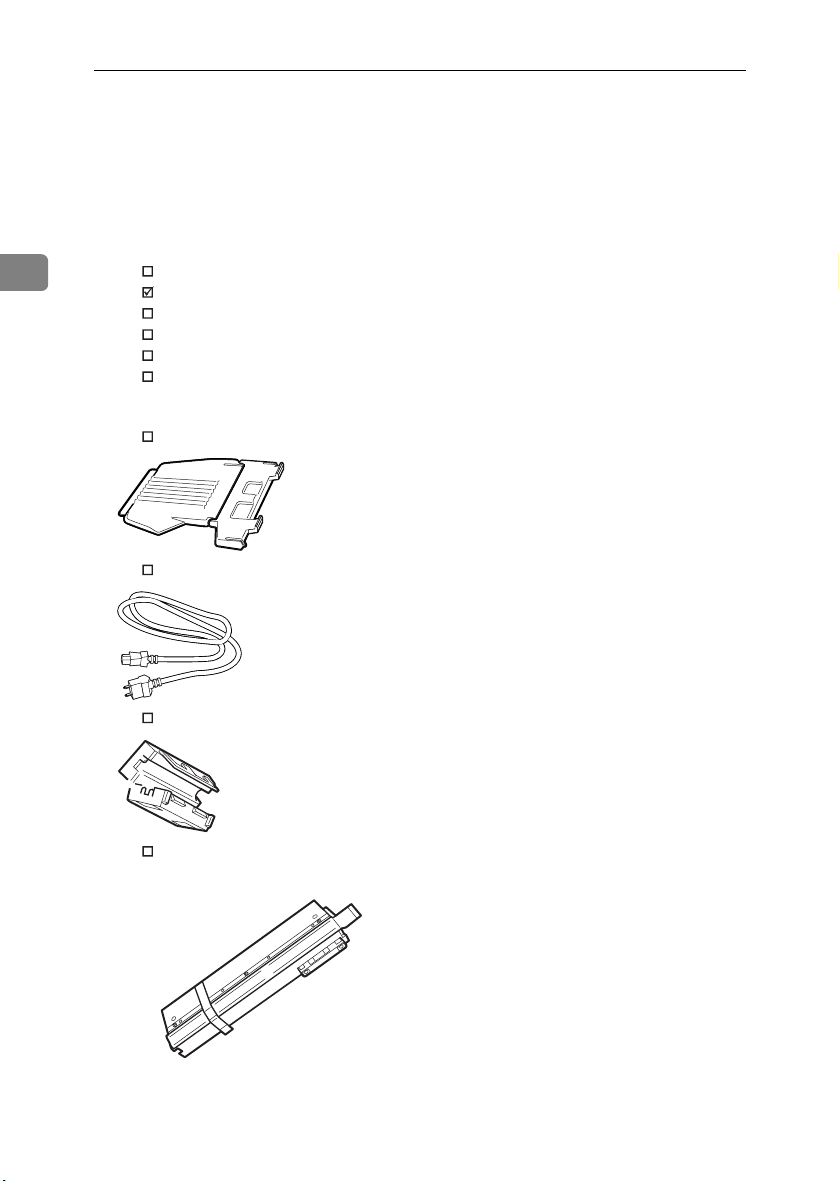
❖❖❖❖ Parts
External Tray
Power Cable
10
Ferrite Core
Fuser Oil Unit
Page 23
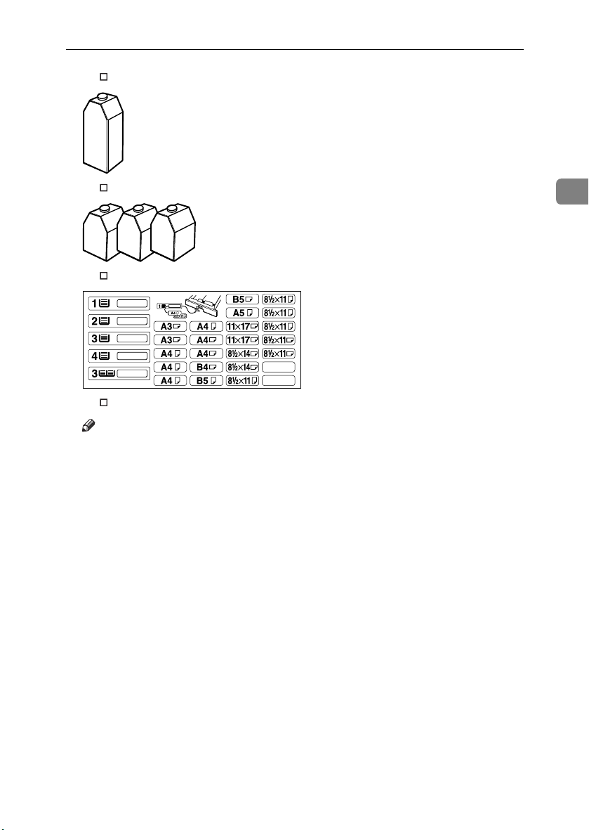
Black Toner Cartridge (K)
Checking the Contents of the Box
Magenta (M), Cyan (C), Yellow (Y) Toner Cartridges
Paper Feed Unit Labels
Additional Documentation
Note
❒ This package does not include an interface cable. Please purchase one to
use with your host computer. See “Appendix”, Administrator Reference.
2
11
Page 24
Setting Up
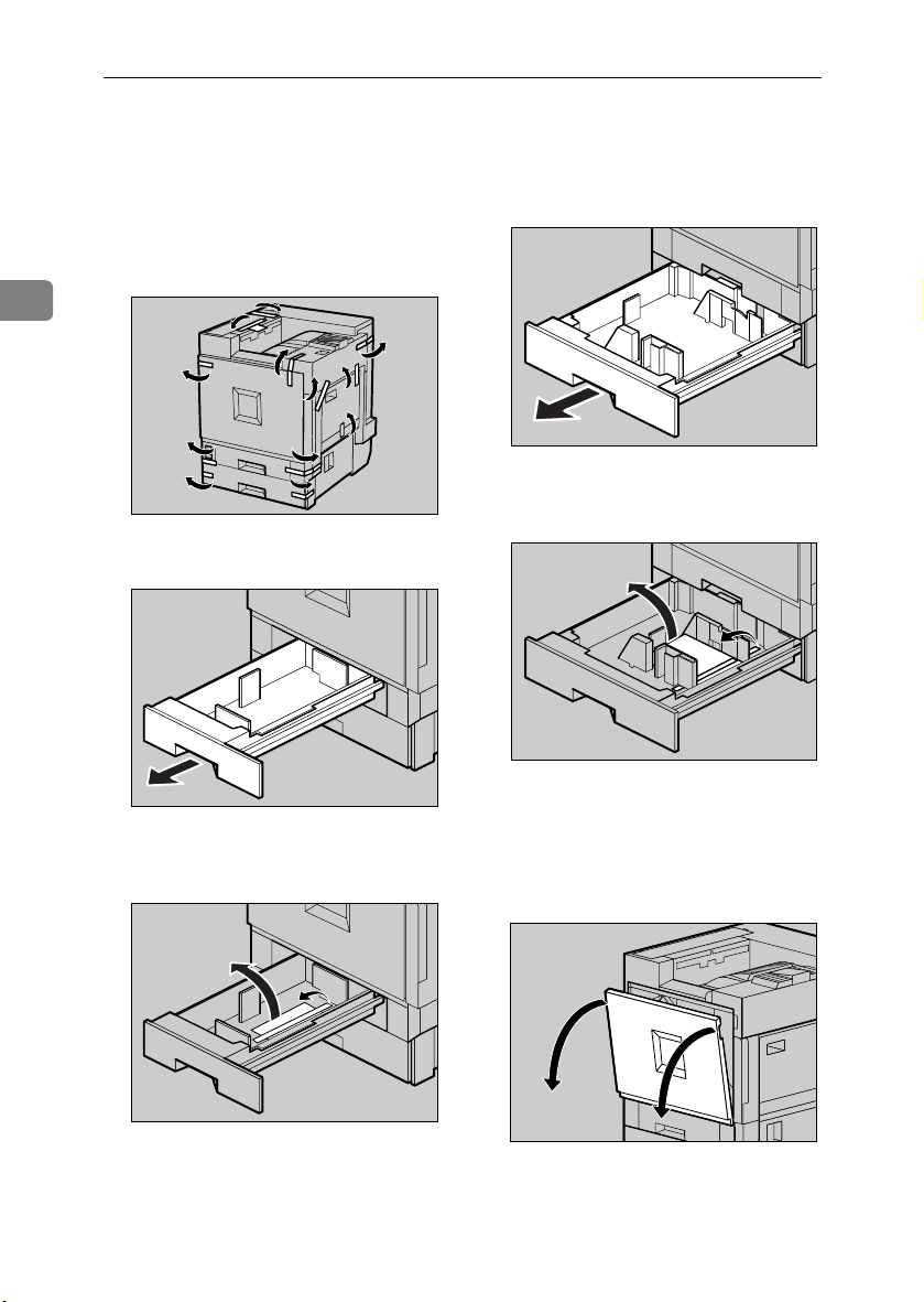
Unpacking
Remove the adhesive tape from
AAAA
the printer body. Remove the
cardboard taped to the standard
tray.
Open Tray 2.
EEEE
2
ZDJH005J
Remove the adhesive tape and
FFFF
Open Tray 1.
BBBB
ZDJH001J
ZDJH003J
sheet of paper.
Close Tray 2 slowly.
GGGG
ZDJH006J
12
Remove the adhesive tape and
CCCC
sheet of paper.
Close Tray 1 slowly.
DDDD
ZDJH004J
Open the front cover slowly by
HHHH
pulling down using the upper left
and right sides.
ZDJH007J
Page 25
Unpacking
Important
❒ Do not place objects on the
opened front cover.
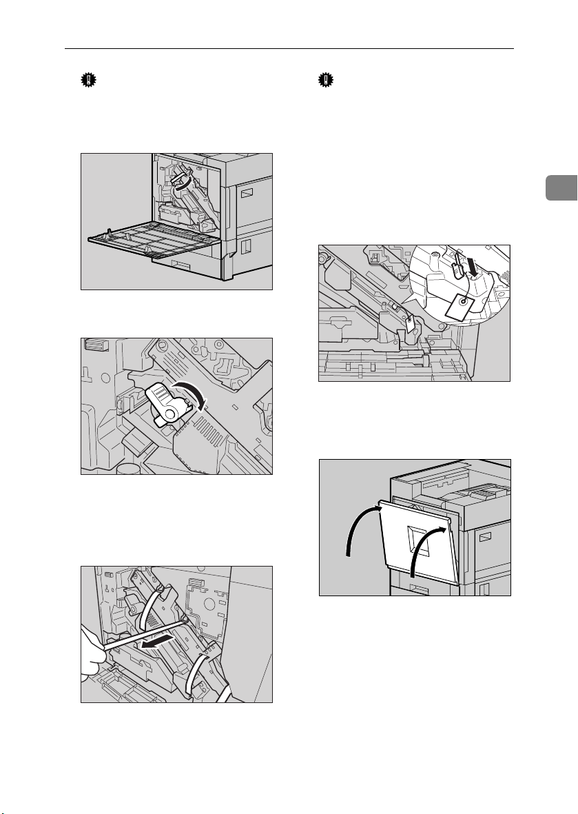
Remove the adhesive tape.
IIII
Turn the green lever clockwise.
JJJJ
ZHXHK110J
ZHXH420J
Important
❒ Be sure to pull out all four piec-
es of tape to avoid printer malfunction during operation.
❒ The removed tape is dirty. Be
careful not to let it touch your
hands or clothes.
Remove the securing pin, as
LLLL
shown, from the transfer unit.
Pinch it, and then pull it out.
Close the front cover slowly by
MMMM
pushing the two areas on the left
and right.
2
ZHXH131J
Slowly pull out the four pieces of
KKKK
tape coming out of the development unit, in a horizontal direction.
ZDJH041J
ZHXH130J
13
Page 26
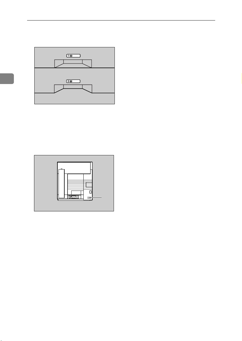
Setting Up
Put labels “1” and “2” on the front
NNNN
of the paper trays.
2
ZDJP129J
A sticker, stating that paper for an
OOOO
ink-jet printer cannot be used
with this printer, is supplied.
Please attach this to the near right
corner of the printer's top [A], so it
is easy to see.
14
A
ZDJX005E
Page 27
Installing the Fuser Oil Unit
R
Installing the Fuser Oil Unit
CAUTION:
• Keep the fuser oil unit away from
flames. There is a risk of fire or
burns.
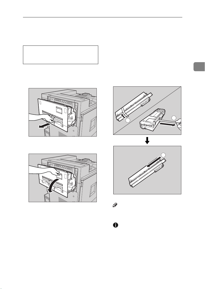
Install the fuser oil unit in the fusing
unit.
Slowly pull out the left cover.
AAAA
ZHXH010J
Open the upper left cover.
BBBB
Take the fuser oil unit out of the
CCCC
bag. Hold the green upper part of
seal (AAAA), and then slowly peel it
off. Position the fuser oil unit as
shown, and then slowly pull it
(AAAA) out. Finally, hold the upper
part of seal (BBBB), and then slowly
peel it off.
1
2
2
1
ZHXH020J
ZHXHK041J
Note
❒ Be sure to remove seal (A), and
then pull it out horizontally.
Important
❒ Be sure to remove the seals to
avoid printer malfunction.
❒ Be sure to remove seal (A) first,
and then remove seal (B) to
avoid oil leakage.
❒ After removing the seals, be
careful not to let oil from oilsupplying parts or the seals
come into contact with your
body or clothes.
15
Page 28
Setting Up
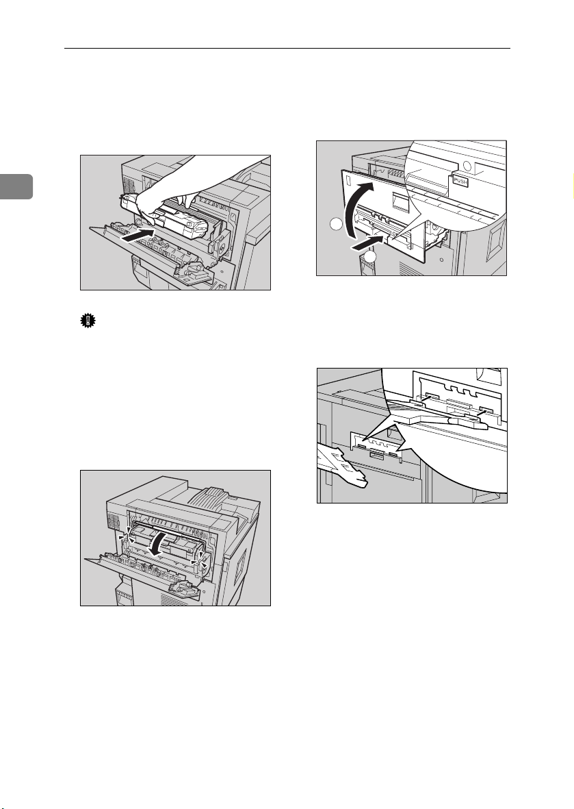
As shown, hold the fuser oil unit
DDDD
using one hand, and the green
handle with the other, and then
slowly insert the unit horizontally, in the direction of the arrow.
Close the upper left cover (AAAA),
FFFF
and then push the part labeled
PUSH next to the handle at the
bottom rear, until it clicks (BBBB).
2
1
2
ZHXH082J
ZHXH060J
Attach the external tray to the
Important
❒ Be careful not to get oil on the
top metal part of the fuser oil
unit.
❒ Insert the fuser oil unit firmly
until it stops.
Slowly turn the fuser unit handle
EEEE
in the direction of the arrow, until
it clicks.
GGGG
printer. Insert the hooks of the external tray into the printer slits,
and then lower it toward you.
16
ZDJH010J
ZHXH070J
Page 29
Installing the Toner Cartridge
R
R
Installing the Toner Cartridge
WARNING:
• Do not incinerate spilled toner
or used toner. Toner dust is
flammable and will ignite
when exposed to an open
flame.
• Disposal should take place at
an authorized dealer or an appropriate collection site. If you
dispose of the used toner cartridges yourself, dispose of
them according to local regulations.
CAUTION:
• Keep toner (used or unused) and
the toner cartridge out of reach
of children.
Note
❒ The toner cartridge allows you to
print up to about 20,000 pages in
black, and about 10,000 pages in
color. These numbers were obtained from printing A4K 5%
charts, but the actual number of
pages will differ depending on the
paper type, size, contents and settings.
Open the upper right cover.
AAAA
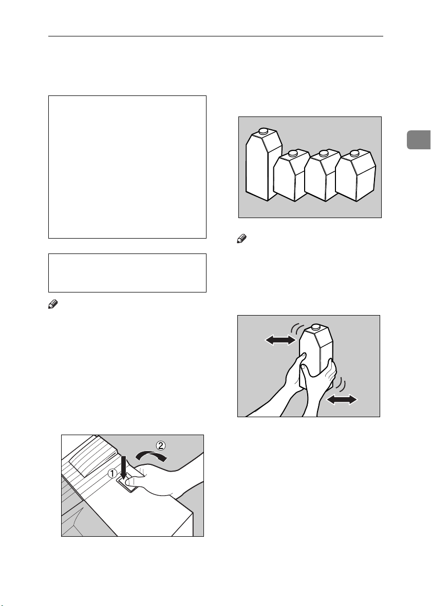
Take out the toner cartridges from
BBBB
the box.
Note
❒ The black (K) toner cartridge
contains more toner than the
others.
Shake the toner cartridge back
CCCC
and forth five or six times.
2
ZDJT202J
ZDJT203J
ZDJT006J
17
Page 30
Setting Up
Holding the toner cartridge with
DDDD
the metal contact area in front, insert in the direction of the arrow.
Insert each cartridge into the same
color slot.
Use the same procedure to insert
FFFF
the remaining three toner cartridges.
Close the upper right cover.
GGGG
2
ZDJH042J
Important
❒ Be careful not to touch the metal
contact point with your fingers.
Insert the toner cartridge slowly,
EEEE
until the green hook snaps on the
metal contact area.
ZDJT004J
Important
❒ Do not turn off the power
switch while “Loading Toner...
” appears on the display to
avoid malfunction.
18
ZDJT005J
Important
❒ Do not insert and remove toner
cartridges repeatedly, as this
could result in toner leakage.
Page 31

Loading Paper
Loading Paper
This section describes how to load paper in the paper tray. If you do not
load paper, the setup procedure will
not be properly complete.
The side guide and end guide of each
paper tray is set to the following values at factory default. The loading
procedure is different if you choose to
load paper that is a different size from
that of factory default.
See p.19 “Loading Paper in Tray 1”.
❖❖❖❖ Default of the paper tray
• Tray 1 (standard): A4K only
• 2000-sheet Large Capacity Tray
(optional): A4K only
For details about size and feed orientation of paper that can be loaded in
the tray, see “Paper and Other Media”, Maintenance Guide.
For details about loading paper in the
bypass tray, see “Loading Paper in
the Bypass Tray”, Maintenance Guide.
Loading Paper in Tray 1
Important
❒ Tray 1 is A4K paper only. Load
only A4 size paper.
Slowly slide the paper tray out,
AAAA
until it stops.
ZDJH003J
Align all four sides of the paper
BBBB
stack, and then load it in the tray.
ZDJY001J
Important
❒ Make sure the top of the stack is
not higher than the limit mark
inside the tray.
❒ Be sure to adjust the side guides
according to the paper size, or
paper misfeeds might occur.
Slowly slide the paper tray back,
CCCC
until it stops.
Loading Paper in Tray 2 and
the Optional Paper Feed Unit
Paper of different sizes can be loaded
in Tray 2 (standard) and the 500- and
1000-sheet paper feed units (optional)
by adjusting the positions of the side
and end guides.
Note
❒ If the side and end guides are in
the right positions for the paper to
be loaded, the guides do not have
to be adjusted.
• Tray 2 (standard): B5L
• 500-sheet paper feed unit: A3L
• 1000-sheet paper feed unit: A3L
2
19
Page 32

Setting Up
Slowly slide the paper tray out,
AAAA
until it stops.
Adjust the end guide according to
CCCC
the size and orientation of the paper by gripping both edges of the
guide (AAAA), and then moving it in
the direction of the arrow (BBBB).
2
ZDJH005J
Adjust the side guide according
BBBB
to the size and orientation of the
paper, as follows:
A Release the side guide lock.
ZDJY950J
B Press the green lever of the
side guide (AAAA), and then adjust
the position of the guide by
moving it in the direction of
the arrow (BBBB).
Align all four sides of the paper
DDDD
stack, and then load it in the tray.
Important
❒ Make sure the top of the stack is
not higher than the limit mark
inside the tray.
ZHXH760J
ZDJY901J
20
ZDJY802J
Make sure the paper is fixed in
EEEE
place, and then lock the side
guide.
ZDJY007J
Page 33

Loading Paper
Slowly slide the paper tray back,
FFFF
until it stops.
Important
❒ Do not slide the paper tray in
with force. If you do, the front
and side guides might move.
❒ Be sure to adjust the side guides
according to the paper size, or
misfeeds might occur.
2000-sheet Large Capacity
Tray
Important
❒ The 2000-sheet Large Capacity
Tray is set to A4K as default.
❒ If you want to load letter-size (11 ×
1
8
/2) paper in the 2000-sheet Large
Capacity Tray (optional), contact
your sales or service representative.
Slowly slide the paper tray out,
AAAA
until it stops.
Align all four sides of the paper
BBBB
stack, and then load two stacks
next to each other.
Important
❒ Be sure to align the paper and
load them against the left and
right walls, or a paper misfeed
could occur.
❒ Make sure the top of the stack is
not higher than the limit mark
inside the tray.
Slowly slide the paper tray back,
CCCC
until it stops.
Important
❒ Do not slide in the paper tray
forcefully. This may skew the
paper stack and cause misfeeds.
2
ZDJY009J
ZDJY008J
21
Page 34

Setting Up
R
Turning the Power On
WARNING:
• Plug and unplug the power cable with dry hands, or an electric shock could occur.
2
Make sure the power switch is set
AAAA
to “bbbb” Off.
Connect the power cable to the
BBBB
connector on the back of the
printer.
ZDJH029J
Turn the power switch to “aaaa”
DDDD
On.
ZDJH031J
22
Plug in the power cable.
CCCC
Important
❒ Make sure the power cable is
plugged securely into the wall
outlet.
❒ Turn the power switch off when
plugging and unplugging the
power plug.
ZDJH030J
Page 35

Selecting the Display Language
Selecting the Display Language
Select a language using the procedure
described here.
The message for the selected language will appear on the display.
Note
❒ The default setting is English.
❒ If you want to use the display in
English, the following procedures
are unnecessary.
Press {{{{Menu}}}}.
AAAA
ZDJS001J
The menu appears on the display.
Press {{{{UUUU}}}} or {{{{TTTT}}}} to display “Lan-
BBBB
guage”.
The following message appears on
the display:
Language:
*English
Press {{{{UUUU}}}} or {{{{TTTT}}}} until the lan-
DDDD
guage you want to select appears.
Press {{{{Enter #}}}}. Wait for two sec-
EEEE
onds.
The menu appears on the display.
Press {{{{On Line}}}}.
FFFF
“Ready” message appears on the
display.
2
ZDJS022J
Menu:
Language
Press {{{{Enter #}}}}.
CCCC
Ready
ZDJS021J
23
Page 36

Setting Up
Test Printing
Test print in order to check that the
printer is working normally. Test
printing checks printer performance;
it does not test the connection to the
2
computer.
Here, you can print the configuration
page to check the options.
The machine may make a rustling
sound while printing. However, this
does not indicate a malfunction and
will disappear after about 1000 sheets
have been printed.
Press {{{{Menu}}}}.
AAAA
ZDJS001J
The menu appears on the display.
Menu
Paper Input
Press {{{{UUUU}}}} or {{{{TTTT}}}} to display
BBBB
“List/Test Print”, and then press
{{{{Enter#}}}}.
Press {{{{UUUU}}}} or {{{{TTTT}}}} to display the
CCCC
“Config. Page”, and then press
{{{{Enter#}}}}.
List/Test Print
Config. Page
The following message appears
and the configuration page is
printed.
Printing...
Note
❒ If printing is not normal, check
to see if an error message appears on the display. If there is
an error message, see “Trouble-
shooting”, Maintenance Guide.
Check the options.
DDDD
Note
❒ For details about the configura-
tion page, see “Interpreting the
Configuration Page”, Adminis-
trator Reference.
Press {{{{On Line}}}}.
EEEE
“Ready” appears on the display.
24
Menu
List/Test Print
The menu for selecting the contents to be test printed appears.
Page 37

3. Preparing to Print
Connecting the Printer
Connecting to a Network
Turn off the power.
AAAA
Loop the network interface cable
BBBB
and attach the ferrite core.
Connect the other end of the cable
DDDD
to the network, such as a hub connection.
For details about network environment settings, see Administrator
Reference.
Note
❒ The network interface cable
loop should be about 15 cm (6”)
(A) from the end of the cable
(the end closest to the printer).
Connect the network interface ca-
CCCC
ble to the port on the right side of
the printer.
Reading the LED lamps
1
2
ZDJH032J
1.
Yellow: lights up when 100BASETX is being used. Turns off when
10BASE-T is being used.
2.
Green: lights up when the printer
is connected properly to the network.
ZDJP103J
25
Page 38

Preparing to Print
Parallel Connection
Use an interface cable to connect the
printer to the computer with a parallel connection. The parallel interface
cable is not provided with the printer.
Note
❒ The printer's parallel connection is
a standard bidirectional interface.
3
It requires a standard 36-pin parallel cable compliant with IEEE 1284,
and a parallel port on the host
computer.
❒ Use shielded interface cables. Us-
ing unshielded cables could result
in radio interference noise.
Turn off the printer and compu-
AAAA
ter.
Attach the parallel cable to the
BBBB
printer's port. Secure the cable
with the metal fittings, as shown.
26
Important
❒ Voltage rating of the parallel
port for the computer: max. DC
5V.
Attach the other end of the paral-
CCCC
lel cable to the port of the computer. Secure the cable.
For details about settings for parallel connection printing, see Printer
Client Reference.
ZDJH033J
Page 39

Configuring the Printer for the Network using the Control Panel
Configuring the Printer for the Network
using the Control Panel
You must make printer settings using
the control panel to use it in a network environment.
The following list shows the items
you can set and their default values.
Reference
For information about the “Host
Interface” menu, see “ Host Interface Menu”, Administrator Refer-
ence (PDF file on the CD-ROM
labeled “Operating Instructions”).
Setting Name Default
DHCP On
IP address
Subnet mask
Gateway address
Frame type (NW)
(frame type NetWare)
Active protocol TCP/IP
Ethernet Auto
*1
*2
*1
*1
If DHCP is in use, IP address, subnet
mask, and gateway address are automatically set.
❍ means the protocol is active.
011.022.033.044
000.000.000.000
*1
000.000.000.000
Auto
NetWare
NetBEUI
AppleTalk
*2
❍
*2
❍
*2
❍
*2
❍
Press {{{{Menu}}}}.
AAAA
The menu appears on the display.
Press {{{{UUUU}}}} or {{{{TTTT}}}} to display “Host
BBBB
Interface” and then press {{{{Enter
#}}}}.
Menu:
Host Interface
The interface setting menu ap-
pears.
The procedure below describes
CCCC
how to set TCP/IP. Make settings
for other items by following the
same procedure.
Note
❒ The default settings for all pro-
tocols are “Active”.
❒ You are recommended to set
unused protocols “Not Active”.
A Press {{{{UUUU}}}} or {{{{TTTT}}}} to display
“Network Setup”, and then
press {{{{Enter #}}}}.
3
ZDJS001J
Host Interface:
Network Setup
27
Page 40

Preparing to Print
B Press {{{{UUUU}}}} or {{{{TTTT}}}} to display
“Active Protocol”, and then
press {{{{Enter #}}}}.
Network Setup:
Active Protocol
C Press {{{{UUUU}}}} or {{{{TTTT}}}} to display
“TCP/IP”, and then press {{{{Enter #}}}}.
3
Active Protocol:
TCP/IP
D
{{{{UUUU}}}}
Press
tive”, and then press
or
{{{{TTTT}}}}
to display “Ac-
{{{{
Enter #
}}}}
.
TCP/IP:
*Active
Note
❒ * shows the current setting.
After about two seconds, the
display returns to the “Active
Protocol” setting screen.
E Set the rest of the protocols for
use.
F When all settings for protocols
are done, press {{{{Escape}}}}.
The “Network Setup” setting
screen appears.
When you use this machine in
DDDD
DHCP environment, proceed to
. When you use this ma-
step
FFFF
chine with a fixed IP address, you
must make the setting for the required item after setting DHCP to
Off. Proceed to step AAAA.
Important
❒ When DHCP is On, you cannot
make settings for the following
items:
• IP Address
• Subnet Mask
28
• Gateway Address
Note
❒ Consult your network adminis-
trator for information about
making network settings.
A Set DHCP to Off.
B Press
{{{{UUUU}}}}
{{{{TTTT}}}}
or
to display “DH-
CP”, and then press
{{{{
Enter #
}}}}
.
Network Setup:
DHCP
C Press {{{{UUUU}}}} or {{{{TTTT}}}} to display
“Off”, and then press {{{{Enter #}}}}.
The current IP address appears
on the display.
DHCP:
*Off
Note
❒ * shows the current setting.
After about two seconds, the
display returns to the “Network
Setup” setting screen.
D Set the printer IP address.
Note
❒ Confirm the IP address with
the network administrator.
E Press {{{{UUUU}}}} or {{{{TTTT}}}} to display “IP
Address”, and then press {{{{Enter
#}}}}.
Network Setup:
IP Address
The currently selected IP address appears.
Note
❒ When {{{{Enter #}}}} is pressed,
the cursor moves to the next
field.
❒ When {{{{UUUU}}}} or {{{{TTTT}}}} is kept
pressed for a few seconds,
the value changes in increments of 10.
Page 41

Configuring the Printer for the Network using the Control Panel
F Press {{{{UUUU}}}} or {{{{TTTT}}}} to set the val-
ue for the field.
IP Address:
199.022.033.044
G Press {{{{Enter #}}}}.
The cursor moves to the next
field.
H Repeat FFFF and GGGG to set values
for the rest of the fields.
Set “Subnet Mask” and “Gate-
EEEE
way Address” using the same
procedure for setting the IP address.
Important
❒ The subnet mask is the part of
the IP address used as a network address. Confirm the value with the network
administrator.
❒ The gateway address is the ad-
dress of the host or router that
acts as a gateway when interacting with work stations on another network. Confirm the
value with the network administrator.
Print the configuration page to
GGGG
confirm the settings made.
See p.24 “Test Printing” for details
about printing the configuration
page.
3
Note
❒ If you are not sure about ad-
dress settings, leave them as default.
When all settings are made, press
FFFF
{{{{On Line}}}}.
“Ready” appears on the display.
Ready
29
Page 42
Preparing to Print
Installing the Printer Driver
You can install the printer drivers and
other software easily using the CDROM labeled “Printer Drivers and
Utilities”.
Click [Quick Install] in the window of
the CD-ROM to install PCL 5c and
TM
RPCS
3
PostScript 3 printer driver, click the
PostScript 3 printer driver button. For
details about the PostScript 3 printer
driver, see the Administrator Reference
or the Printer Client Reference on the
CD-ROM labeled “Operating Instructions” (depending on the environment you use).
When TCP/IP is used, SmartNetMonitor for Client will also be installed.
Supported operating systems are
Windows 95/98/Me, Windows 2000,
Windows XP, and Windows NT 4.0.
When using TCP/IP, confirm the following:
• The printer is connected to a net-
• TCP/IP is set.
• IP addresses are set for the printer
AAAA
printer drivers. To install the
work with ethernet cable.
and the computer.
Insert the CD-ROM labeled
“Printer Drivers and Utilities”
into the CD-ROM drive.
Auto Run will start the installer.
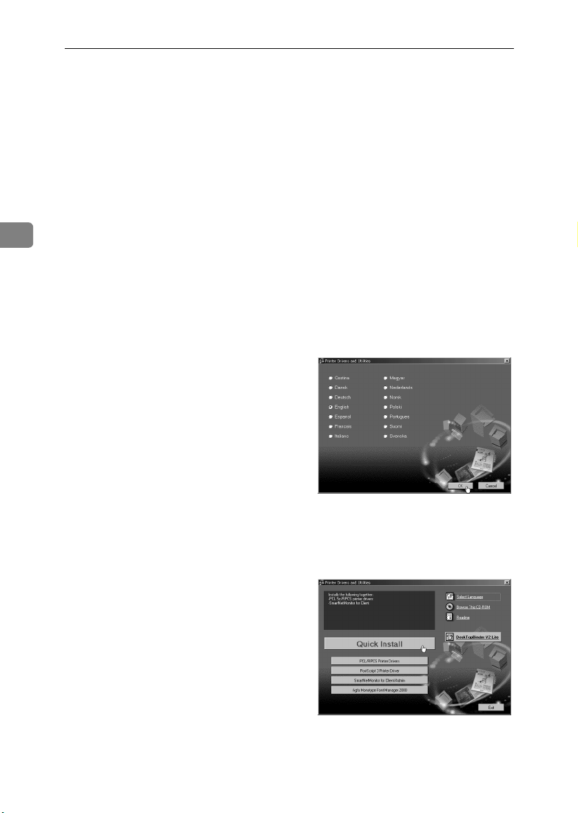
Select a language for the inter-
BBBB
face, and then click [OK].
The following languages are avail-
able:
Cestina (Czech), Dansk (Danish),
Deutsch (German), English (Eng-
lish), Espanol (Spanish), Francais
(French), Italiano (Italian), Magyar
(Hungarian), Nederlands (Dutch),
Norsk (Norwegian), Polski
(Polish), Portugues (Portuguese),
Suomi (Finnish), Svenska (Swed-
ish)
The default interface language is
English.
Click [Quick Install].
CCCC
The software license agreement
appears in the [
dialog box.
License Agreement
]
30
This is an example screen that ap-
pears when English is selected in
.
step
B
Page 43

Installing the Printer Driver
After reading through the con-
DDDD
tent, click [
agree with the License Agreement, and then click [
Select the printer model you want
EEEE
to install in the [Select Printer] dialog box.
Note
❒ For a network connection with
TCP/IP, select the printer
whose IP address is displayed
in [Connect to].
❒ For parallel connection, select
the printer whose printer port is
displayed in [
I accept the agreement
].
Next
Connect to
].
] to
Click [Install].
FFFF
The following display appears
when installing the printer driver.
When finished, the [Installation
Completion] dialog box appears.
Click [Finish].
GGGG
Note
❒ A message directing you to re-
start the computer may appear.
If this happens, restart your
computer to complete the installation. If no such message
appears, proceed to step
Click [Exit].
HHHH
3
.
H
Installation is now complete.
31
Page 44

Preparing to Print
3
32
Page 45

R
4. Installing Options
Installing Options
CAUTION:
• Before installing options, the machine should be turned off, and then unplugged for at least an hour. Components inside the machine become very
hot, and can cause a burn if touched.
• Before moving the machine, unplug the power cable from the outlet. If the
cable is unplugged with sudden force, it could become damaged. Damaged
plugs or cables can cause an electrical fire hazard.
• When lifting the machine, use the grips on both sides. The machine could
break or cause injury if dropped.
By installing options, you can improve printer performance and have a greater
variety of features to use. For details about each option, see Administrator Refer-
ence.
When installing multiple options on the printer, we recommend installation in
the following order.
❖❖❖❖ Flow of Option Installation
A
Attach the 500, 1000-sheet paper feed unit, or 2000-sheet
Large Capacity Tray.
(Paper Feed Unit Type 3800C,
Paper Bank PS470)
T
B
Install the SDRAM module.
(Memory Unit TypeC)
T
C
Installing the 1394 interface
unit, USB 2.0 interface board,
802.11b interface unit or Blue-
TM
unit.
tooth
(1394 Interface Unit Type 4510)
(USB 2.0 Interface Board Type
A)
(802.11b Interface Unit Type A)
(Bluetooth Unit Type 2045)
T
Attach the paper feed unit to the bottom of the printer.
You can install the Paper Feed Unit Type 3800C (500 × 1),
Paper Feed Unit Type 3800C (500 × 2) or Paper Bank
PS470.
If you install the Paper Bank PS470, you can load up to
3,100 sheets of paper at once.
Install the module in the controller board's SDRAM module slot.
There are three types of Memory Unit TypeC: 64 MB, 128
MB, and 256 MB.
Install the 1394 interface unit, USB interface board,
802.11b interface unit or Bluetooth unit on the controller
board.
The 1394 interface unit and the standard Ethernet interface cannot be used at the same time.
Only one of the following can be installed:
• 1394 interface unit
• USB interface board
• 802.11b interface unit
• Bluetooth unit
*1
33
Page 46

Installing Options
D
Install the user account enhance
unit
(User Account Enhance Unit
TypeC)
T
E
Install the printer hard disk.
(Printer Hard Disk Type 7000)
T
F
Attach the duplex unit.
4
(Duplex Unit Type 7000)
T
G
Attach the 2 tray finisher.
(SR770)
T
H
Attach the 4-bin mailbox.
(Mail Bin Type 3800C)
*1
The bypass tray is included.
Install the module to the user account enhance unit slot of
the controller board.
Install the Printer Hard Disk Type 7000 to the controller
board.
Attach the duplex reversal unit to the left side of the printer, and the duplex feed unit inside the printer.
Attach the 2 tray finisher to the left side of the printer.
You cannot install the 2 tray finisher unless both the paper
feed unit and duplex unit options are installed.
If you choose to install the 4-bin mailbox, you cannot install the 2 tray finisher.
The 2 tray finisher requires the optional printer hard disk
or the optional memory unit with at least 64 MB (total
memory size 128 MB or more).
Remove the upper cover to attach Mail Bin Type 3800C.
If you choose to install the 2 tray finisher, you cannot install the 4-bin mailbox.
Install options in the positions as shown.
34
Page 47

❖❖❖❖ Exterior
Installing Options
4
1.
Paper Feed Unit Type 3800C (500
×××× 1)
Loads up to 500 sheets (500 sheets × 1
column) of paper.
See p.38 “Installing the Paper Feed
Unit Type 3800C (500 × 1)”.
2.
Paper Feed Unit Type 3800C (500
×××× 2)
Loads up to 1,000 sheets (500 sheets ×
2 columns) of paper.
See p.41 “Installing the Paper Feed
Unit Type 3800C (500 × 2)”.
3.
Paper Bank PS470 (2000-sheet
Large Capacity Tray)
Loads up to 2,000 sheets (2,000 sheets
× 1 column) of paper.
See p.43 “Installing the Paper Bank
PS470 (2000-sheet Large Capacity
Tray)”.
ZHXH140J
4.
SR770 (2 Tray Finisher)
Performs Job Separation, staples and
punches holes. Install the finisher on
the left side of the printer.
See p.80 “SR770 (2 Tray Finisher)”.
5.
Mail Bin Type 3800C (4-bin Mail-
box)
Sorts printed documents from multiple users. Attach the mailbox to the
top of the printer.
See p.87 “Mail Bin Type 3800C (4-bin
Mailbox)”.
6.
Duplex Reversal Unit
Flips over the paper during duplex
printing. Install the unit on the left
side of the printer.
See p.76 “Installing the Duplex Reversal Unit”.
35
Page 48

Installing Options
7.
Duplex Feed Unit
Transports paper during duplex
printing. Install the unit inside the
printer.
See p.76 “Installing the Duplex Reversal Unit”.
Important
❒ You cannot install the 2 tray finisher unless both the paper feed unit and
duplex unit options are attached.
❒ You cannot install the 2 tray finisher unless at least the optional 128MB
SDRAM module, or printer hard disk is installed.
❒ You cannot install both the 2 tray finisher and 4-bin mailbox at the same
time.
4
❖❖❖❖ Interior
1
3
2
1.
Memory Unit TypeC (SDRAM
Module)
Install 64 MB, 128 MB, or 256 MB
RAM into the controller board slot.
See p.46 “ Memory Unit TypeC
(SDRAM Module)”.
2.
1394 interface unit/USB interface
board/802.11b interface unit/Bluetooth unit
See p.48 “1394 Interface Unit Type
4510”.
See p.54 “USB 2.0 Interface Board
Type A”.
See p.57 “802.11b Interface Unit Type
A”.
See p.63 “Bluetooth Unit Type 2045”.
36
ZHXP011J
3.
User Account Enhance Unit
TypeC
See p.66 “User Account Enhance Unit
TypeC”.
4.
Printer Hard Disk Type 7000
Install the printer hard disk to the controller board.
See p.69 “Printer Hard Disk Type
7000”.
4
Page 49

Using the Screwdriver
Using the Screwdriver
The special screwdriver used for attaching options is attached to the inside of the
front cover. By pushing the screw top into the screwdriver, you can work without having to worry about dropping the screw.
ZHXH170J
Note
❒ After using the screwdriver, return it to its original position on the inside of
the front cover.
4
37
Page 50

Installing Options
R
R
Paper Feed Unit
Preparation
If you want to use the optional du-
plex unit, 2 tray finisher or 4-bin
mailbox at the same time, install
the optional paper feed unit first,
and then install these options.
If you have already installed the
optional duplex unit, 2 tray finish-
er and 4-bin mailbox, remove all
these options before installing the
4
optional paper feed unit.
Important
❒ Before installation, check the ori-
entation of the paper feed unit or
2000-sheet Large Capacity Tray
you want to place.
❒ When installing multiple options,
install the paper feed unit first.
❒ Four people are needed to install
the paper feed unit. Start installa-
tion when all four people are
ready.
CAUTION:
• When moving the machine, each
person should hold a handle, located on two sides of the printer,
and then lift slowly. Lifting carelessly or dropping it may cause
injury.
Note
❒ The printer weighs approximately
85 kg (187 lbs).
Installing the Paper Feed Unit
Type 3800C (500 ×××× 1)
CAUTION:
• When moving the paper feed
unit, hold the bottom of both
sides, and then lift slowly. Lifting
carelessly or dropping it may
cause injury.
Note
❒ The 500-sheet paper feed unit
weighs approximately 18 kg (39.7
lbs).
Turn off the power, and then un-
AAAA
plug the power cable.
Remove the adhesive tape.
BBBB
ZDJP004J
Adjust the four corners of the
CCCC
printer to those of the 500-sheet
paper feed unit, and then lower
the printer slowly into place.
38
ZDJP006J
Page 51

Paper Feed Unit
Important
❒ Four people should hold the
handles, located on two sides of
the printer, to move it.
Open the tray of the 500-sheet pa-
DDDD
per feed unit.
A Remove the adhesive tape and
sheet of paper.
B Remove the adhesive tape and
the corrugated paper inside the
tray, as shown.
ZDJP007J
Take out the packaged items,
EEEE
making sure there are two thumb
screws and one mounting bracket. Close the tray of the 500-sheet
paper feed unit firmly.
Slowly pull out Tray 2 while lift-
FFFF
ing up a little.
ZDJP005J
4
ZDJX801J
Fasten one thumb screw. A coin
GGGG
can be used to fasten the screws.
Slowly slide Tray 2 back into the
HHHH
printer, until it stops.
ZHXH852J
ZDJP009J
39
Page 52

Installing Options
Open the right cover of the 500-
IIII
sheet paper feed unit.
ZHXH860J
Hook the mounting bracket to the
4
JJJJ
hole, as shown.
Fasten the bracket with the other
KKKK
thumb screw. A coin can be used
to fasten the screws.
ZHXH870J
Stick label “3” above the handle
MMMM
on the front of the 500-sheet paper
feed unit.
Note
❒ After finishing the installation,
you can check the 500-sheet paper feed unit is installed properly: Print the configuration page
from the “ List/Test Print”
menu. If it is installed properly,
you will see “Paper Feed Unit
(Tray 3)” appear under the “Op-
tions” list.
❒ If the paper feed unit is not in-
stalled properly, repeat the procedure from step
cannot install it properly even
after reinstallation, contact your
sales or service representative.
. If you
A
ZDJP126J
40
Close the right cover of the 500-
LLLL
sheet paper feed unit.
Reference
p.24 “Test Printing”
ZDJP012J
Page 53

Paper Feed Unit
R
Installing the Paper Feed Unit
Type 3800C (500 ×××× 2)
CAUTION:
• When moving the paper feed
unit, hold the bottom of both
sides, and then lift slowly. Lifting
carelessly or dropping it may
cause injury.
Note
❒ The 1000-sheet paper feed unit
weighs approximately 25 kg (55.2
lbs).
Turn off the power, and then un-
AAAA
plug the power cable.
Remove the adhesive tape.
BBBB
Important
❒ Four people should hold the
handles, located on two sides of
the printer, to move it.
Open the tray of the 1000-sheet
DDDD
paper feed unit.
A Remove the adhesive tape and
sheet of paper.
B Remove the adhesive tape and
the corrugated paper inside the
tray, as shown.
ZDJP007J
4
Adjust the four corners of the
CCCC
printer to those of the 1000-sheet
paper feed unit, and then slowly
lower the printer into place.
ZDJP013J
ZDJX801J
ZDJP014J
41
Page 54

Installing Options
Take out the packaged items,
EEEE
making sure there are two thumb
screws and one mounting bracket. Close the tray of the 1000-sheet
paper feed unit firmly.
4
Slowly pull out Tray 2 while lift-
FFFF
ing up a little.
Fasten one thumb screw. A coin
GGGG
can be used to fasten the screws.
ZDJP005J
ZHXH853J
Open the right cover of the 1000-
IIII
sheet paper feed unit.
Hook the mounting bracket to the
JJJJ
hole, as shown.
Fasten the bracket with the other
KKKK
thumb screw. A coin can be used
to fasten the screws.
ZHXH050N
ZHXH060N
42
Slowly slide Tray 2 back into the
HHHH
printer, until it stops.
ZDJP015J
Close the right cover of the 1000-
LLLL
sheet paper feed unit.
ZDJP018J
Page 55

Stick labels “3” and “4” above the
R
MMMM
handles on the front of the 1000sheet paper feed unit.
Paper Feed Unit
Installing the Paper Bank
PS470 (2000-sheet Large
Capacity Tray)
CAUTION:
• When moving the paper feed
unit, hold the bottom of both
sides, and then lift slowly. Lifting
carelessly or dropping it may
cause injury.
ZDJP127J
Note
❒ After finishing the installation,
you can check the 1000-sheet
paper feed unit is installed
properly: Print the configuration page from the “List/Test
Print” menu. If it is installed
properly, you will see “Paper
Feed Unit (Tray 3 & Tray 4)” appear under the “Options” list.
❒ If the paper feed unit is not in-
stalled properly, repeat the procedure from step
cannot install it properly even
after reinstallation, contact your
sales or service representative.
Reference
p.24 “Test Printing”
. If you
A
Note
❒ The 2000-sheet Large Capacity
Tray weighs approximately 25 kg
(55.2 lbs).
Turn off the power, and then un-
AAAA
plug the power cable.
Remove the adhesive tape.
BBBB
ZDJP019J
Adjust the four corners of the
CCCC
printer to those of the 2000-sheet
Large Capacity Tray, and then
slowly lower the printer into
place.
4
ZDJP020J
43
Page 56

Installing Options
Important
❒ Four people should hold the
handles, located on two sides of
the printer, to move it.
4
Take out the packaged items,
DDDD
making sure there are two thumb
screws and one mounting bracket. Close the tray of the 2000-sheet
Large Capacity Tray firmly.
ZDJP007J
Fasten one thumb screw. A coin
FFFF
can be used to fasten the screws.
Slowly slide Tray 2 back into the
GGGG
printer, until it stops.
Open the right cover of the 2000-
HHHH
sheet Large Capacity Tray.
ZDJP021J
44
Slowly pull out Tray 2 while lift-
EEEE
ing up a little.
ZDJP005J
ZHXH851J
Hook the mounting bracket to the
IIII
hole, as shown.
ZHXH070N
ZHXH080N
Page 57

Paper Feed Unit
Fasten the bracket with the other
JJJJ
thumb screw. A coin can be used
to fasten the screws.
Close the right cover of the 2000-
KKKK
sheet Large Capacity Tray.
Stick label “3” above the handle
LLLL
on the front of the 2000-sheet
Large Capacity Tray.
ZDJP024J
❒ If the paper feed unit is not in-
stalled properly, repeat the procedure from step
cannot install it properly even
after reinstallation, contact your
sales or service representative.
Reference
p.24 “Test Printing”
. If you
A
4
ZDJP128J
Note
❒ After finishing the installation,
you can check the 2000-sheet
Large Capacity Tray is installed
properly: Print the configuration page from the “List/Test
Print” menu. If it is installed
properly, you will see “LCT
Tandem Bank” appear under
the “Options” list.
45
Page 58

Installing Options
Memory Unit TypeC (SDRAM Module)
Important
❒ Before handling the memory unit,
ground yourself by touching
something metal to discharge any
static electricity. Static electricity
can damage the memory unit.
❒ Do not subject the SDRAM Mod-
ule to physical shocks.
Turn off the power, and then un-
AAAA
plug the power cable.
4
Slowly open the front cover of the
BBBB
printer, remove the green screwdriver, and then close the cover.
Reference
p.37 “Using the Screwdriver”
Remove the two screws fastening
CCCC
the controller board to the back of
the printer using the provided
screwdriver.
Holding the handle, slowly pull
DDDD
out the controller board.
Put the controller board down on
EEEE
a flat surface.
Release the locks on the left and
FFFF
right sides of the open slot.
ZDJP025J
46
ZDJP025J
The removed screws will be used
later to fasten the controller board.
Align the notch of the memory
GGGG
unit with the slot, and then insert
vertically.
ZDJP027J
ZDJP028J
Page 59

Memory Unit TypeC (SDRAM Module)
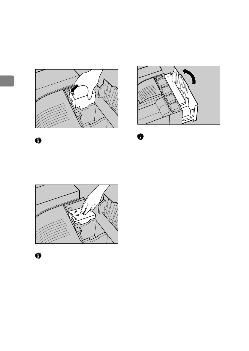
Press the memory unit down until
HHHH
it clicks into the locked position.
Align the controller board with
IIII
the top and bottom rails, and then
push in slowly, until it stops.
ZDJP029J
ZDJP030J
Note
❒ Be sure to return the provided
screwdriver to its original position on the inside of the front
cover.
❒ After finishing the installation,
you can check the memory unit
is installed properly: Print the
configuration page from the
“List/Test Print” menu. If it is
installed properly, you will see
the memory capacity for “Total
Memory”.
❒ If the memory unit is not in-
stalled properly, repeat the procedure from step
cannot install it properly even
after reinstallation, contact your
sales or service representative.
Reference
p.24 “Test Printing”
. If you
A
4
Tighten the two screws fastening
JJJJ
the controller board back into its
original position, using the provided screwdriver.
ZDJP031J
47
Page 60

Installing Options
1394 Interface Unit Type 4510
Important
❒ Printing using “1394/SCSI Print-
er” (Windows 2000) device and
“IEEE 1394 and SCSI printers”
(Windows XP) with the optional
1394 interface unit is possible under Windows 2000 and Windows
XP. Printing with IP over 1394 is
possible under Windows Me and
Windows XP.
4
❒ Printing is not possible with Win-
dows 95, 98. If the “plug and play”
function starts, click [Cancel].
❒ Under Windows 2000, the 1394 in-
terface unit can only be used with
Service Pack 1 or later. If the Service Pack is not installed, only one
SCSI print device in a 1394 bus is
connectable. The client cannot install the printer driver without an
account that has Administrators
permission.
❒ Before handling the 1394 interface
unit, ground yourself by touching
something metal to discharge any
static electricity. Static electricity
can damage the 1394 interface unit
❒ Unplug all interface cables from
the printer before installation. If
you take out the controller board
with cables still plugged in, the
1394 interface unit might be damaged.
❒ Do not plug or unplug the 1394 in-
terface cable while installing the
printer driver
❒ Use the 1394 Interface cable sup-
plied with the 1394 interface unit.
❒ Do not subject the 1394 interface
unit to physical shocks.
Check the contents of the box.
AAAA
❖❖❖❖ 1394 Interface Unit Type 4510
❖❖❖❖ Interface Cable (6 pin ×××× 6 pin)
❖❖❖❖ Interface Cable (6 pin ×××× 4 pin)
Turn off the power, and then un-
BBBB
plug the power cable, and then interface cable.
Slowly open the front cover of the
CCCC
printer, remove the green screwdriver, and then close the cover.
Reference
p.37 “Using the Screwdriver”
ZHBP400E
48
Page 61

1394 Interface Unit Type 4510
Remove the two screws fastening
DDDD
the controller board to the back of
the printer using the provided
screwdriver.
The removed screws will be used
later to fasten the controller board.
Holding the handle, slowly pull
EEEE
out the controller board.
ZDJP025J
Note
❒ The removed screws will be
needed in step
Install the 1394 interface unit into
HHHH
the controller board. Insert the tip
of the 1394 interface unit into the
attachment area (AAAA), and then
push it in the direction of the arrow (BBBB).
Check the 1394 interface unit is
connected firmly to the controller
board.
Using the screwdriver provided,
IIII
tighten the two screws removed
in step
face unit.
, securing the 1394 inter-
GGGG
.
I
4
ZHXP040J
Put the controller board down on
FFFF
a flat surface.
Remove the small cover plate us-
GGGG
ing the provided screwdriver, as
shown.
ZDJP025J
ZHXP131J
ZHXP140J
49
Page 62

Installing Options
Insert the controller board into
JJJJ
the top and bottom rails, and then
slide it in slowly, until it stops.
❒ If the 1394 interface unit is not
installed properly, repeat the
procedure from step
cannot install it properly even
after reinstallation, contact your
sales or service representative.
Reference
p.24 “Test Printing”
. If you
A
Connecting the Cable to the
1394 Interface Unit
ZDJP030J
Connect the interface cable to the
4
Tighten the two screws fastening
KKKK
the controller board back into its
original position, using the provided screwdriver.
AAAA
1394 interface port.
ZDJP500J
50
ZDJP803J
Note
❒ Be sure to return the provided
screwdriver to its original position on the inside of the front
cover.
❒ After finishing the installation,
you can check the 1394 interface
unit is installed properly: Print
the configuration page from the
“List/Test Print” menu, and
then check the items in “System
Reference”. If it is installed
properly, you will see
“IEEE1394” appear under
“Controller Option”.
Note
❒ Either of the two connectors for
the 1394 interface unit can be
used.
❒ If you have an interface cable
with a ferrite core, connect the
end nearest to the ferrite core to
the printer.
Connect the other end to the host
BBBB
computer.
Page 63

IEEE 1394 Configuration
Use this procedure to configure the
printer for use in an IEEE 1394 environment. The following table shows
the control panel settings and their
default values. These items are included in the “Host Interface” menu.
Setting Name Value
IP Address1394 000.000.000.000
Subnet Mask1394 000.000.000.000
IP over 1394 Active
SCSI print Active
Bidi-SCSI print Active
Procedures vary depending on the
protocol you use. See the following
table.
IP over 1394 Steps A-H, and then
SCSI print Steps A-D, and then
Press {{{{Menu}}}}.
AAAA
proceed to steps M to
N
proceed to steps I to
N
1394 Interface Unit Type 4510
Press {{{{Enter #}}}}.
CCCC
The following message appears on
the display:
Host Interface:
I/O Buffer
Press {{{{UUUU}}}} or {{{{TTTT}}}} to display “IEEE
DDDD
1394 Setup”.
Host Interface:
IEEE 1394 Setup
Press {{{{Enter #}}}}.
EEEE
The following message appears on
the display:
ZDJS021J
4
The menu appears on the display.
Press {{{{UUUU}}}} or {{{{TTTT}}}} to display the
BBBB
“Host Interface” menu.
Menu:
Host Interface
ZDJS001J
IEEE 1394 Setup:
IP Address1394
Press {{{{UUUU}}}} or {{{{TTTT}}}} to display “IP
FFFF
over 1394”.
IEEE 1394 Setup:
IP over 1394
A Press {{{{Enter #}}}}.
B Press {{{{UUUU}}}} or {{{{TTTT}}}} to select ei-
ther “Active” or “Not Active”.
C Press {{{{Enter #}}}}.
After a few seconds, the display
returns to the previous menu.
51
Page 64

Installing Options
Assign the IP address to the print-
GGGG
er.
Do not overlap the IP address in
the same subnet or the same IP address in the network setting.
Note
❒ To get the IP address for the
printer, contact your network
administrator.
A Press {{{{UUUU}}}} or {{{{TTTT}}}} until the fol-
lowing message appears:
4
IEEE 1394 Setup:
IP Address1394
B Press {{{{Enter #}}}}.
The current IP address appears
on the display.
IP Address1394:
000.000.000.000
C Press {{{{UUUU}}}} or {{{{TTTT}}}} to enter the
leftmost entry field of the IP
address.
IP Address1394:
❒ If you press {{{{Escape}}}} when
the cursor (k) is in the leftmost position, the selected IP
address is reset.
E Repeat steps CCCC and DDDD to enter
the IP address.
IP Address1394:
192.168.000.011
Check the cursor (k) is in the
rightmost position, and then
press {{{{Enter #}}}} to register the IP
address you selected.
IEEE 1394 Setup:
IP Address1394
Set “Subnet Mask1394” in the
HHHH
same way.
Set “SCSI print” and “Bidi-SCSI
IIII
print” if necessary.
Note
❒ Default is “Active”.
Press {{{{UUUU}}}} or {{{{TTTT}}}} to display “SCSI
JJJJ
print”.
192.000.000.000
IEEE 1394 Setup:
D Press {{{{Enter #}}}}.
The cursor (k) moves to the next
entry field automatically.
IP Address1394:
SCSI print
Press {{{{Enter #}}}}.
KKKK
The following message appears on
the display:
192.02k.000.000
SCSI print:
Note
❒ The value changes in incre-
ments of 10 if {{{{UUUU}}}} or {{{{TTTT}}}} is
kept pressed.
❒ You can return the cursor (k)
to the previous (left) entry
field by pressing {{{{Escape}}}}.
*Active
Press {{{{UUUU}}}} or {{{{TTTT}}}} to select either
LLLL
“Active” or “Not Active”, and
then press {{{{Enter #}}}}.
Set “Bidi-SCSI print” in the same
way.
52
Page 65

Press {{{{On Line}}}}.
MMMM
“Ready” appears on the display.
Ready
Print a configuration page to con-
NNNN
firm the settings made. See p.24
“Test Printing”.
1394 Interface Unit Type 4510
4
53
Page 66

Installing Options
USB 2.0 Interface Board Type A
Important
❒ The USB 2.0 interface board sup-
ports a USB connection between
the printer and a computer running Windows 98 SE/Me, Windows 2000/XP, Mac OS 9.x or Mac
OS X Classic mode.
❒ With Windows 98 SE/Me, be sure
to install USB Printing Support
from the CD-ROM provided with
4
the machine. When USB 2.0 is used
with Windows 98 SE/Me, only the
same speed as that of USB 1.1 is
possible.
❒ Only the standard USB port is sup-
ported on a Macintosh
❒ When using USB with a Macin-
tosh, only the same speed as that of
USB 1.1 is possible
❒ Before handling the USB 2.0 inter-
face board, ground yourself by
touching something metal to discharge any static electricity. Static
electricity can damage the USB 2.0
interface board
❒ Do not subject the USB 2.0 inter-
face board to physical shocks.
❒ Buy a USB cable suitable for your
computer.
Turn off the power, and then un-
BBBB
plug the power cable, and then interface cable.
Slowly open the front cover of the
CCCC
printer, remove the green screwdriver, and then close the cover.
Reference
p.37 “Using the Screwdriver”
Remove the two screws fastening
DDDD
the controller board to the back of
the printer using the provided
screwdriver.
The removed screws will be used
later to fasten the controller board.
Holding the handle, slowly pull
EEEE
out the controller board.
ZDJP025J
54
Check the contents of the box.
AAAA
❖❖❖❖ USB 2.0 Interface Board Type A
ZHXP100J
Put the controller board down on
FFFF
a flat surface.
ZDJP025J
Page 67

USB 2.0 Interface Board Type A
Remove the small cover plate us-
GGGG
ing the provided screwdriver, as
shown.
Note
❒ The removed screws will be
needed in step
Install the USB 2.0 interface
HHHH
board into the controller board.
Insert the tip of the USB 2.0 interface board into the attachment
area (AAAA), and then push it in the
direction of the arrow (BBBB).
.
I
ZHXP140J
Using the screwdriver provided,
IIII
tighten the two screws removed
in step
terface board.
Insert the controller board into
JJJJ
the top and bottom rails, and then
slide it in slowly, until it stops.
, securing the USB 2.0 in-
GGGG
ZHXP132J
4
ZHXP020J
Check the USB 2.0 interface board
is connected firmly to the controller board.
Tighten the two screws fastening
KKKK
the controller board back into its
original position, using the provided screwdriver.
ZDJP030J
ZHXH881J
55
Page 68

Installing Options
Note
❒ Be sure to return the provided
screwdriver to its original position on the inside of the front
cover.
❒ After finishing the installation,
you can check the USB 2.0 interface board is installed properly:
Print the configuration page
from the “List/Test Print”
menu, and then check the items
in “System Reference”. If it is installed properly, you will see
4
“USB” appear under “Controller Option”.
❒ If the USB 2.0 interface board is
not installed properly, repeat
the procedure from step
you cannot install it properly
even after reinstallation, contact
your sales or service representative.
Reference
p.24 “Test Printing”
. If
A
Connecting the Cable to the
USB 2.0 Interface Board
Connect the square-shaped con-
AAAA
nector of the USB cable to the
USB 2.0 interface board.
ZHXH880J
Connect the opposite end's flat
BBBB
connector to devices such as the
USB interface of the computer, or
USB hub.
56
Page 69

802.11b Interface Unit Type A
802.11b Interface Unit Type A
Important
❒ Before handling the 802.11b inter-
face unit, ground yourself by
touching something metal to discharge any static electricity. Static
electricity can damage the 802.11b
interface unit
❒ Do not subject the 802.11b interface
unit to physical shocks.
Limitation
❒ The 802.11b interface unit and Eth-
ernet interface cannot be used at
the same time.
❒ If problems occur with printing
due to of poor radio reception,
connect an external antenna.
Check the contents of the box.
AAAA
❖❖❖❖ 802.11b Interface Unit Type A
• Interface Unit
Turn off the power, and then un-
BBBB
plug the power cable and interface cable.
Slowly open the front cover of the
CCCC
printer, remove the green screwdriver, and then close the cover.
Reference
p.37 “Using the Screwdriver”
Remove the two screws fastening
DDDD
the controller board to the back of
the printer using the provided
screwdriver.
The removed screws will be used
later to fasten the controller board.
4
ZDJP025J
• Card
ZHBP410E
ZHXP240J
Holding the handle, slowly pull
EEEE
out the controller board.
Put the controller board down on
FFFF
a flat surface.
ZDJP025J
57
Page 70

Installing Options
Remove the small cover plate us-
GGGG
ing the provided screwdriver, as
shown.
ZHXP140J
4
Note
❒ The removed screws will be
needed in step
Install the 802.11b interface unit
HHHH
into the controller board. Insert
the tip of the 802.11b interface
unit into the attachment area (AAAA),
and then push it in the direction
of the arrow (BBBB).
.
I
Using the screwdriver provided,
IIII
tighten the two screws removed
in step
terface unit.
With the label facing down and
JJJJ
the uneven black antenna surface
facing up, slowly insert the card
into the 802.11b interface unit, until it stops.
, securing the 802.11b in-
GGGG
ZHXP130J
58
ZHXP030J
Check the 802.11b interface unit is
connected firmly to the controller
board.
Insert the controller board into
KKKK
the top and bottom rails, and then
slide it in slowly, until it stops.
ZHXP050J
ZDJP030J
Page 71
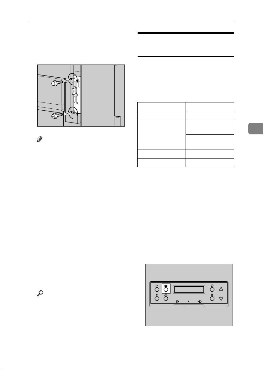
Tighten the two screws fastening
LLLL
the controller board back into its
original position, using the provided screwdriver.
Note
❒ Be sure to return the provided
screwdriver to its original position on the inside of the front
cover.
❒ After finishing the installation,
you can check the 802.11b interface unit is installed properly:
Print the configuration page
from the “List/Test Print”
menu, and check the items in
“System Reference”. If it is installed properly, you will see
“IEEE 802.11b” appear under
“Controller Option”.
❒ If the 802.11b interface unit is
not installed properly, repeat
the procedure from step
you cannot install it properly
even after repeat the procedure,
contact your sales or service
representative.
ZHXP200J
A
. If
802.11b Interface Unit Type A
IEEE 802.11b (wireless LAN)
Configuration
Configure the printer to use the IEEE
802.11b (wireless LAN). The following table shows the control panel settings and their default values. These
items are included in the “Host Interface” menu.
Setting Name Default Value
Comm. Mode 802.11 Ad hoc
Channel • Inch version
Trans. Speed Auto
WEP Setting Not Active
To use the IEEE 802.11b (wireless
LAN), select “IEEE 802.11b” for
“LAN Type” in “Network Setup” of
the “Host Interface” menu, and then
set “IP Address”, “Subnet Mask”,
“Gateway Address”, “ DHCP”,
“Frame Type (NW)” and “Active Pro-
tocol” in the “Network Setup”. For
details about setting the items in the
“Network Setup”, see p.27 “Configuring the Printer for the Network using the Control Panel”.
Press {{{{Menu}}}}.
AAAA
(1-11) 11
• Metric version
(1-13) 11
4
Reference
p.24 “Test Printing”
ZDJS001J
The menu appears on the display.
59
Page 72

Installing Options
Press {{{{UUUU}}}} or {{{{TTTT}}}} to display “Host
BBBB
Interface” menu.
Menu:
Host Interface
Press {{{{Enter #}}}}.
CCCC
4
ZDJS021J
The following message appears on
the display:
Host Interface:
I/O Buffer
Press {{{{UUUU}}}} or {{{{TTTT}}}} to display “IEEE
DDDD
802.11b”.
Press {{{{UUUU}}}} or {{{{TTTT}}}} to select the
GGGG
transmission mode.
Note
❒ Default is “802.11 Ad hoc”.
❒ To use an IEEE 802.11b card for
which the SSID (Network
Name) setting is not necessary,
select “Ad hoc”.
Press {{{{Enter #}}}}.
HHHH
After a few seconds, the display returns to the previous menu.
If “802.11 Ad hoc” or “Ad hoc” is
IIII
selected for “Comm. Mode”, set
the channel for transmission.
Note
❒ Check with the network admin-
istrator about the channel to
use.
A Press {{{{UUUU}}}} or {{{{TTTT}}}} to display
“Channel”.
IEEE 802.11b:
Channel
60
Host Interface:
IEEE 802.11b
Press {{{{Enter #}}}}.
EEEE
Check that “Comm. Mode” ap-
pears on the display.
IEEE 802.11b:
Comm. Mode
Press {{{{Enter #}}}}.
FFFF
The following message appears on
the display:
Comm. Mode:
*802.11 Ad hoc
B Press {{{{Enter #}}}}.
The channel currently in use appears on the display.
Channel:
(1-11) 11
C Press {{{{UUUU}}}} or {{{{TTTT}}}} to enter the
channel.
D Press {{{{Enter #}}}}.
Set “Trans. Speed” in the same
JJJJ
way.
Note
❒ Default is “Auto”. If you need to
change the transmitting speed
depending on the environment
you are using, select the appropriate speed.
Page 73

802.11b Interface Unit Type A
Press the {{{{UUUU}}}} or {{{{TTTT}}}} key to dis-
KKKK
play “SSID”, and then press the
{{{{Enter #}}}} key.
IEEE 802.11b:
SSID
The following message appears on
the display:
SSID:
Enter ID
Note
❒ Default is “ASSID”.
❒ If an SSID has been set, you can
check it. Press the {{{{UUUU}}}} or {{{{TTTT}}}}
key to display “View”, and then
press the {{{{Enter #}}}} key.
A Press the {{{{Enter #}}}} key.
The following message appears
on the display:
SSID: [ 0]
k
Note
❒ The value in brackets at the
upper right indicates the
number of characters entered.
B Press the {{{{UUUU}}}} or {{{{TTTT}}}} key to se-
lect characters, and then press
the {{{{Enter #}}}} key.
SSID: [ 1]
A
Note
❒ Usable characters are ASCII
0x20-0x7e (32 bytes).
❒ If you press the {{{{Escape}}}} key,
the cursor (k) moves to the
previous character position.
D After entering, press the {{{{Enter
#}}}} key twice.
SSID: [32]
AAAAAAAAAAAAAAAA
The screen returns to step
Press the {{{{UUUU}}}} or {{{{TTTT}}}} key to dis-
LLLL
play “WEP Setting”.
IEEE 802.11b:
WEP Setting
A Press the {{{{Enter #}}}} key.
WEP Setting:
*Not Active
B Press the {{{{UUUU}}}} or {{{{TTTT}}}} key to dis-
play “Active”, and then press
the {{{{Enter #}}}} key.
WEP Setting:
Active
The following message appears
on the display:
Change WEP Key:
Yes
.
K
4
The cursor (k) moves to the next
character position.
SSID: [ 1]
A
k
C Continue entering.
61
Page 74
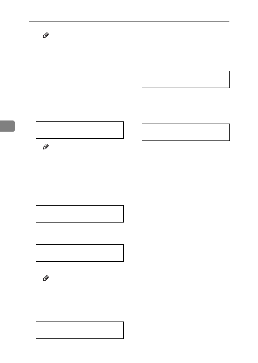
Installing Options
Note
❒ When setting WEP to “Ac-
tive”, you need to enter the
WEP key. If you have not entered the key, be sure to enter
it.
❒ If you have entered the WEP
key, and then change the setting, press the {{{{UUUU}}}} or {{{{TTTT}}}}
key to display “No”, and
then press the {{{{Enter #}}}} key.
C Press the {{{{Enter #}}}} key.
4
WEP Key: [ 0]
k
Note
❒ The value in brackets at the
upper right indicates the
number of characters entered.
D Press the {{{{UUUU}}}} or {{{{TTTT}}}} key to se-
lect characters, and then press
the {{{{Enter #}}}} key.
❒ If you press the {{{{Escape}}}} key,
the cursor (k) moves to the
previous character position.
F After entering, press the {{{{Enter
#}}}} key.
WEP Key: [26]
0000000000000000
The screen returns to step
Press {{{{On Line}}}}.
MMMM
“Ready” appears on the display.
Ready
Print a configuration page to con-
NNNN
firm the settings made. See p.24
“Test Printing”.
.
L
WEP Key: [ 1]
0
62
The cursor (k) moves to the next
character position.
WEP Key: [ 1]
0
k
E Continue entering.
Note
❒ You can enter either 10 or 26
characters. If the key you enter is not 10 or 26 characters
long, the following message
appears:
Error: Enter 10
or 26 characters
Page 75

Bluetooth Unit Type 2045
Bluetooth Unit Type 2045
Important
❒ Only Bluetooth-equipped comput-
ers support printing with the Bluetooth unit.
❒ Before handling the Bluetooth in-
terface unit, ground yourself by
touching something metal to discharge static electricity. Static electricity can damage the Bluetooth
interface unit.
❒ Do not subject the Bluetooth unit
to physical shocks.
Reference
The manual provided with the
Bluetooth unit.
Check the contents of the box.
AAAA
❖❖❖❖ Bluetooth
• Interface Unit
• Antenna Cap
ZHBPA921E
Turn off the power, and then un-
BBBB
plug the power cable and interface cable.
Slowly open the front cover of the
CCCC
printer, remove the green screwdriver, and then close the cover.
Reference
p.37 “Using the Screwdriver”
Remove the two screws fastening
DDDD
the controller board to the back of
the printer using the provided
screwdriver.
4
• Card
ZHBP410E
ZHBP510E
ZDJP025J
The removed screws will be used
later to fasten the controller board.
63
Page 76

Installing Options
Holding the handle, slowly pull
EEEE
out the controller board.
ZDJP025J
Put the controller board down on
4
FFFF
a flat surface.
Remove the small cover plate us-
GGGG
ing the provided screwdriver, as
shown.
Install the Bluetooth unit into the
HHHH
controller board. Insert the tip of
the Bluetooth unit into the attachment area (AAAA), and then push it in
the direction of the arrow (BBBB).
Check the Bluetooth unit is connected firmly to the controller
board.
Tighten the two screws fastening
IIII
the Bluetooth unit, using the provided screwdriver.
ZHXP030J
64
ZHXP140J
Note
❒ The removed screws will be
needed in step
.
I
ZHXP120J
Page 77

Bluetooth Unit Type 2045
With the side labeled INSERT
JJJJ
facing up, slowly insert the card
into the Bluetooth unit, until it
stops.
Insert the controller board into
KKKK
the top and bottom rails, and then
slide it in slowly, until it stops.
Tighten the two screws fastening
LLLL
the controller board back into its
original position, using the provided screwdriver.
ZHXP060J
ZDJP030J
Press the antenna to extend it.
MMMM
Attach the antenna cap over the
NNNN
antenna.
Note
❒ Be sure to return the provided
screwdriver to its original position on the inside of the front
cover.
❒ After finishing the installation,
you can check the Bluetooth
unit is installed properly: Print
the configuration page from the
“List/Test Print” menu. If it is
installed properly, you will see
“Bluetooth” appear under
“Controller Option”.
❒ If the Bluetooth unit is not in-
stalled properly, repeat the procedure from step
cannot install it properly even
after reinstallation, contact your
sales or service representative.
. If you
A
ZHXP030N
4
ZHXP220J
Reference
p.24 “Test Printing”
65
Page 78

Installing Options
R
User Account Enhance Unit TypeC
CAUTION:
• Do not place the IC2 lithium battery near or into fire, as it will explode and cause a burn.
• The user account enhance unit
installed on the controller has a
IC2 lithium battery which can explode if replaced incorrectly. Replace the user account enhance
unit only with the indicated one.
4
Note
❒ Disposal should take place at an
authorized dealer or an appropriate collection site. An IC2 lithium
battery is contained inside the user
account enhance unit.
❒ If you are disposing of the unit,
separate the IC2 lithium battery
from the board and dispose of
them according to local regulations.
Important
❒ Before handling the user account
enhance unit, ground yourself by
touching something metal to discharge any static electricity. Static
electricity can damage the user account enhance unit.
❒ Do not subject the user account en-
hance unit to physical shocks.
Check the contents of the box.
AAAA
❖❖❖❖ One Screw
Turn off the power, and then un-
BBBB
plug the power cable.
Slowly open the front cover of the
CCCC
printer, remove the green screwdriver, and then close the cover.
Reference
p.37 “Using the Screwdriver”
Remove the two screws fastening
DDDD
the controller board to the back of
the printer, using the provided
screwdriver.
The removed screws will be used
later to fasten the controller board.
Holding the handle, slowly pull
EEEE
out the controller board.
ZDJP025J
❖❖❖❖ User Account Enhance Unit
ZHXH010N
ZDJP025J
66
Page 79

User Account Enhance Unit TypeC
Put the controller board down on
FFFF
a flat surface.
You must install the user account
enhance unit in the position as
shown.
Install the user account enhance
GGGG
unit into the controller board. If
there is a screw coming out from
the place of attachment, insert the
screw in the hole at the tip of the
user account enhance unit (AAAA),
and then push the unit in the direction of the arrow (BBBB).
ZDJP702J
Tighten the screw fastening the
HHHH
user account enhance unit, using
the provided screwdriver.
Align the controller board with
IIII
the top and bottom rails, and then
push in slowly, until it stops.
ZHXP270N
4
ZDJP030J
ZHXP020N
Check the user account enhance
unit is connected firmly to the controller board.
Tighten the two screws fastening
JJJJ
the controller board back into its
original position, using the provided screwdriver.
ZDJP031J
67
Page 80

Installing Options
Note
❒ Be sure to return the provided
screwdriver to its original position on the inside of the front
cover.
❒ After finishing the installation,
you can check the user account
enhance unit is installed properly: Print the configuration page
from the “List/Test Print”
menu. If it is installed properly,
you will see “Accounting Module” appear under “Controller
4
Option”.
❒ If the user account enhance unit
is not installed properly, repeat
the procedure from step
you cannot install it properly
even after reinstallation, contact
your sales or service representative.
Reference
p.24 “Test Printing”
. If
A
68
Page 81

Printer Hard Disk Type 7000
Printer Hard Disk Type 7000
Important
❒ Before handling the printer hard
disk, ground yourself by touching
something metal to discharge any
static electricity. Static electricity
can damage the printer hard disk.
❒ Do not subject the printer hard
disk to physical shocks.
Check the contents of the box.
AAAA
❖❖❖❖ Printer Hard Disk Type 7000
ZHXP291J
❖❖❖❖ Flat Cable
Turn off the power, and then un-
BBBB
plug the power cable.
Slowly open the front cover of the
CCCC
printer, and remove the green
screwdriver, and then close the
cover.
Reference
p.37 “Using the Screwdriver”
Remove the two screws fastening
DDDD
the controller board to the back of
the printer, using the provided
screwdriver.
The removed screws will be used
later to fasten the controller board.
4
ZDJP025J
❖❖❖❖ Power Cable
❖❖❖❖ Two Screws
Holding the handle, slowly pull
EEEE
out the controller board.
Put the controller board down on
FFFF
a flat surface.
ZDJP025J
69
Page 82

Installing Options
Install the printer hard disk into
GGGG
the controller board.
ZHXP301J
Tighten the two screws fastening
4
HHHH
the printer hard disk to the controller board, using the provided
screwdriver.
Connect the power cable and flat
IIII
cable to the printer hard disk.
ZHXP311J
Connect the flat cable to the con-
JJJJ
troller board.
Remove the white clamp from un-
KKKK
der the printer hard disk, and
then open it, as shown.
Bind the connectors with the
LLLL
clamp, as shown.
ZHXP082J
ZHXP350J
70
ZHXP321J
ZHXP360J
Page 83

Printer Hard Disk Type 7000
Push the clamp hook back in the
MMMM
direction of the arrow, until it
clicks.
Connect the power cable to the
NNNN
controller board.
Align the controller board with
OOOO
the top and bottom rails, and then
push in slowly, until it stops.
ZHXP370J
ZHXP340J
ZDJP030J
Tighten the two screws fastening
PPPP
the controller board back into its
original position, using the provided screwdriver.
The printer hard disk automatically begins formatting when the
printer is switched on.
Note
❒ Be sure to return the provided
screwdriver to its original position on the inside of the front
cover.
❒ After finishing the installation,
you can check the printer hard
disk is installed properly: Print
the configuration page from the
“List/Test Print” menu and
check the items in “System Reference”. If it is installed properly, you will see “Printer Hard
Disk Drive” appear under
“Controller Option”.
❒ If the printer hard disk is not in-
stalled properly, repeat the procedure from step
cannot install it properly even
after reinstallation, contact your
sales or service representative.
. If you
A
ZDJP031J
4
71
Page 84

Installing Options
Formatting the Printer Hard
Disk Drive
If it becomes necessary to format the
printer hard disk after initial setup,
execute “HDD Format” in the “Maintenance” menu.
Important
❒ Formatting the printer hard disk
will delete all data.
Press {{{{Menu}}}}.
AAAA
4
ZDJS001J
The menu appears on the display.
Press {{{{UUUU}}}} or {{{{TTTT}}}} to display “
BBBB
Maintenance”, and then press
{{{{Enter#}}}}.
Note
❒ If “HDD Format” is not dis-
played on the display, the printer hard disk is not installed
properly. Repeat the procedure
from step
Hard Disk Type 7000”. If you
still cannot install it properly,
contact your sales or service
representative.
Important
❒ To avoid malfunction do not
turn off the power while formatting the printer hard disk.
Press {{{{Enter#}}}}.
DDDD
The printer hard disk is formatted,
and a restart message appears.
Turn off the power once, and then
EEEE
turn the power back on.
The printer hard disk format is
completed, and now ready for use.
. See p.69 “Printer
A
72
Menu:
Maintenance
The menu for selecting “Mainte-
nance” items appears.
Press {{{{UUUU}}}} or {{{{TTTT}}}} to display “HDD
CCCC
Format”, and then press {{{{Enter#}}}}.
Maintenance:
HDD Format
A check message appears.
Page 85

Duplex Unit Type 7000
R
R
Duplex Unit Type 7000
Preparation
To use the optional paper feed unit
at the same time, install the optional paper feed unit first, and then install the duplex unit.
CAUTION:
• The inside of the machine becomes very hot. Do not touch the
parts labelled “hot surface”.
Touching a “hot surface” could
result in a burn.
CAUTION:
• Do not let go of the duplex reversal unit until it is fastened in
place. It could fall and cause injury.
Installing the Duplex Reversal
Unit Stand
Check the contents of the box.
AAAA
❖❖❖❖ Stand
❖❖❖❖ One Short Screw, Four Long
Screws
❖❖❖❖ Duplex Reversal Unit
4
❖❖❖❖ Duplex Feed Unit
❖❖❖❖ Paper Guide
73
Page 86

Installing Options
Remove the adhesive tape and
BBBB
packing materials.
Important
❒ Do not remove the adhesive
tape holding the auxiliary bar
yet. Remove it in step
“Installing the Duplex Reversal
Unit”.
❒ Do not remove the adhesive
tape holding the cable of the duplex reversal unit yet. Remove it
in step
Duplex Reversal Unit”.
on p.76 “Installing the
G
on p.76
C
4
ZDJP711J
Lift the external tray in the direc-
EEEE
tion of the arrow (AAAA), and then remove (BBBB).
Remove the two small covers on
FFFF
the upper left cover of the printer.
A Open the upper left cover.
ZDJP038J
74
Turn off the power, and then un-
CCCC
plug the power cable from the
wall outlet.
Slowly open the front cover of the
DDDD
printer, remove the green screwdriver, and then close the cover.
Reference
p.37 “Using the Screwdriver”
ZHXH230J
B Remove the two small covers
by pinching and pulling them
in the direction of the arrow.
ZHXH221J
ZHXH241J
C Close the upper left cover.
Note
❒ You cannot use the two re-
moved covers.
Page 87

Duplex Unit Type 7000
Remove the protective cover on
GGGG
the left side of the printer. Hold
the protective cover by both sides,
and while pushing the left side of
the cover (AAAA), open it in the direction of the arrow (BBBB), and then remove (CCCC).
Note
❒ You cannot use the removed
protective cover.
Attach the paper guide to the
HHHH
stand. Hold it so that the right
side bends down as shown, and
then while gripping lightly (AAAA),
insert it into the holes of the stand
(BBBB).
ZDJP041J
Insert the claws of the stand into
IIII
the holes on the left side of the
printer (AAAA), and then push down
(BBBB).
Tighten the four long screws fas-
JJJJ
tening the duplex reversal unit
stand, using provided screwdriver. Fasten in the order of
AAAA⇒⇒⇒⇒BBBB⇒⇒⇒⇒CCCC⇒⇒⇒⇒DDDD, as shown.
ZDJP043J
4
ZDJP042J
ZDJP044J
This completes installation of the
stand. Next, install the duplex reversal unit.
75
Page 88

Installing Options
Installing the Duplex Reversal
Unit
Using both hands, hold the du-
AAAA
plex reversal unit level, and then
insert the hooks into the groove of
the stand. Align the hook tips
with the line on the stand, as
shown, and then insert slowly.
Do not let go of the duplex reversal unit even after insertion.
While supporting the duplex re-
CCCC
versal unit, remove the adhesive
tape, and then hold the auxiliary
bar in front of the hook on the left
side, and then stand it up.
4
Hook the hole of the auxiliary bar
DDDD
onto the printer's mounting
bracket.
ZHXH250J
The hooks of the duplex reversal
unit clip around the bar inside the
groove of the stand.
While supporting the duplex re-
BBBB
versal unit, remove the stopper
the printer's mounting bracket.
, move the auxiliary bar to
E
ZDJP046J
This stopper will be used in a later
, so take care not to lose it.
step
E
In step
the position with the perforated
line, as shown.
ZDJP047J
ZDJP048J
76
Page 89

Duplex Unit Type 7000
Hang the auxiliary bar on the far
EEEE
left end, as shown, and then install
the stopper removed in step
Make sure the auxiliary bar and
stopper are installed in the positions, as shown.
Slowly raise the duplex reversal
FFFF
unit, and then fold it up to the
printer.
BBBB
.
ZDJP049J
This completes installation of the
duplex reversal unit. Install the
duplex feed unit after the external
tray.
Install the external tray.
HHHH
A Stand the external tray, and
then insert it from the left side
using both hands.
B Pushing the right edge of the
external tray lightly with your
finger (AAAA), insert it (BBBB).
4
ZHXH270J
Remove the adhesive tape hold-
GGGG
ings the cable, and then connect
the cable from the duplex reversal
unit to the upper connector on the
back of the printer.
ZDJP050J
ZDJP053J
C Lower the external tray toward
you.
ZHXH280J
ZHXH260J
77
Page 90

Installing Options
R
Installing the Duplex Feed Unit
Slowly open the front cover by
AAAA
pulling on the two areas on the
left and right.
Holding the duplex feed unit us-
CCCC
ing both hands, place it on the
vertical rail, and then slide it
slowly in until it stops.
4
The vertical rail is in the position,
as shown.
Fasten the duplex feed unit using
DDDD
a short screw and the provided
screwdriver.
Carefully pivot the waste oil bot-
BBBB
tle outward, in the direction of the
arrow.
CAUTION:
• Keep the waste oil bottle away
from flames. There is a risk of
fire or burns.
ZDJH007J
ZHXH150J
ZHXH290J
ZHXH300J
ZHXH310J
78
Page 91

Duplex Unit Type 7000
Note
❒ Be sure to return the provided
screwdriver to its original position on the inside of the front
cover.
This completes installation of the
duplex feed unit.
Carefully push back the waste oil
EEEE
bottle in the direction of the arrow.
Slowly close the front cover slow-
FFFF
ly by pressing the two areas on
the left and right.
ZHXH160J
❒ If the duplex unit is not installed
properly, repeat the procedure
from step
stall it properly even after reinstallation, contact your sales or
service representative.
Reference
p.24 “Test Printing”
Check for leftover parts. You will
GGGG
not need these.
. If you cannot in-
A
4
ZHXH011N
ZDJH041J
Note
❒ After finishing the installation,
you can check the duplex unit is
installed properly: Print the
configuration page from the
“List/Test Print” menu. If it is
installed properly, you will see
“Duplex Unit” appear in the
“Options” list.
79
Page 92

Installing Options
R
SR770 (2 Tray Finisher)
Preparation
Install the 2 tray finisher after the
optional paper feed unit, optional
memory unit or optional printer
hard disk.
First, install the options that allow
the controller board to be installed,
and then the 2 tray finisher.
CAUTION:
• When moving the 2 tray finisher,
4
hold the center of both sides,
and lift slowly. Lifting carelessly
or dropping it may cause injury.
Note
❒ The 2 tray finisher weighs approx-
imately 53 kg (116.9 lbs).
Important
❒ You cannot install the 2 tray finish-
er unless both the paper feed unit
and duplex unit with options are
installed.
❒ The 2 tray finisher requires the op-
tional printer hard disk or optional
memory unit with at least 64 MB
(total memory size 128 MB or
more).
❒ You cannot install the 4-bin mail-
box and 2 tray finisher at the same
time.
Remove the adhesive tape and
BBBB
packing materials.
Important
❒ Do not remove the adhesive
tape holding the cable yet. Remove it in step
.
S
❖❖❖❖ Front and Side
ZDJP059J
ZDJP062J
80
Turn off the power, and then un-
AAAA
plug the power cable.
Page 93

SR770 (2 Tray Finisher)
❖❖❖❖ Back
❖❖❖❖ Interior
ZDJP950J
ZDJP060J
❖❖❖❖ Connecting Bracket
❖❖❖❖ Mounting Bracket
❖❖❖❖ Rail
❖❖❖❖ Two 2 Tray Finisher Trays
Slowly open the front cover of the
DDDD
printer, remove the green screwdriver, and then close the cover.
4
Check the contents of the box.
CCCC
❖❖❖❖ Two short screws, six long screws
ZDJP061J
Reference
p.37 “Using the Screwdriver”
Stand the external tray of the
EEEE
printer.
A Stand it vertically.
ZHXH330J
81
Page 94

Installing Options
B Fold it over the top of the print-
er.
Insert the rail, assembled in step
HHHH
, into the base area under the
FFFF
printer.
ZHXH340J
Insert the rail with a wheel in the
4
FFFF
mounting bracket.
Hook the hole of the mounting
IIII
ZDJP068J
bracket on the screw temporarily
.
GGGG
ZDJP069J
Temporarily fasten one long
GGGG
screw in the position, as shown.
Turn the screw three to four times
by hand.
ZDJP066J
fastened in step
Holding the mounting bracket
JJJJ
using both hands, move it in the
direction of up (AAAA) to the right
(BBBB).
82
ZDJP067J
ZDJP070J
Page 95

SR770 (2 Tray Finisher)
With the left corner of the mount-
KKKK
ing bracket in the position pointed by the arrow on the printer,
fasten the left side of the mounting bracket using a long screw
and the provided screwdriver.
Also tighten the screw on the
right side temporarily fastened in
.
step
GGGG
Reference
p.37 “Using the Screwdriver”
Temporarily fasten the two long
LLLL
screws in the positions shown.
Turn the screws three to four
times by hand.
ZDJP071J
Hook the connecting bracket onto
MMMM
the screws temporarily tightened
in step
Fasten the right side of the con-
NNNN
necting bracket using a long
screw and the provided screwdriver. Also tighten the two
screws temporarily tightened in
step
.
LLLL
.
LLLL
ZDJP073J
4
ZDJP072J
ZDJP074J
Note
❒ If you have the 1000-sheet paper
feed unit or 2000-sheet Large
Capacity Tray installed, proceed to step
.
P
83
Page 96
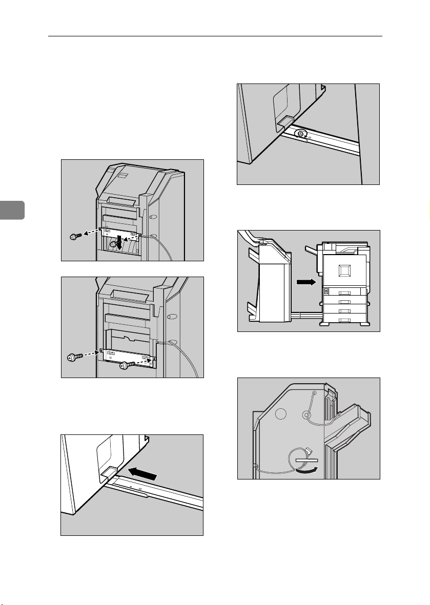
Installing Options
If you have the 500-sheet paper
OOOO
feed unit installed, change the po-
Fasten the rails using a long screw
QQQQ
and the provided screwdriver.
sition of the connecting bracket
on the side of the 2 tray finisher to
the lower level. Remove the two
screws using the provided screwdriver, then move the connecting
bracket down, and then refasten
the screws.
ZDJP078J
Slowly push the 2 tray finisher to-
4
ZDJP075J
RRRR
ward the printer, until it stops.
Remove the tape fastening the ca-
SSSS
ZHXH350J
ble to the 2 tray finisher.
ZDJP076J
84
Place the printer's rail on the 2
PPPP
tray finisher, and then slide until
it stops.
ZDJP080J
ZDJP077J
Page 97

SR770 (2 Tray Finisher)
Connect the cable of the 2 tray fin-
TTTT
isher to the lower connector on
the back of the printer.
Place the two 2 tray finisher trays
UUUU
in the 2 tray finisher.
Note
❒ The two finisher trays are iden-
tical.
A Adjust the notch on the left
side of the 2 tray finisher tray
to the cable coming out from
the 2 tray finisher.
B With the 2 tray finisher tray
laid horizontally, slide it in at a
slant until it stops.
ZDJP083J
C Fasten the finisher tray using a
short screw and the provided
screwdriver.
ZDJP084J
D Use the same steps (BBBB and CCCC)
to install the other 2 tray finisher trays.
4
ZDJP082J
Note
❒ Be sure to return the provid-
ed screwdriver to its original
position on the inside of the
front cover.
85
Page 98

Installing Options
Put the finisher tray installed on
VVVV
the duplex unit back in place.
A Lift the top.
ZHXH360J
4
B Lower slowly.
86
ZHXH370J
Note
❒ After finishing the installa-
tion, you can check the finisher is installed properly:
Print the configuration page
from the “List/Test Print”
menu. If it is installed properly, you will see “2 Tray Finisher” appear in the
“Options” list.
❒ If the Finisher is not installed
properly, repeat the procedure from step
. If you can-
A
not install it properly even
after reinstallation, contact
your sales or service representative.
Reference
p.24 “Test Printing”
Page 99
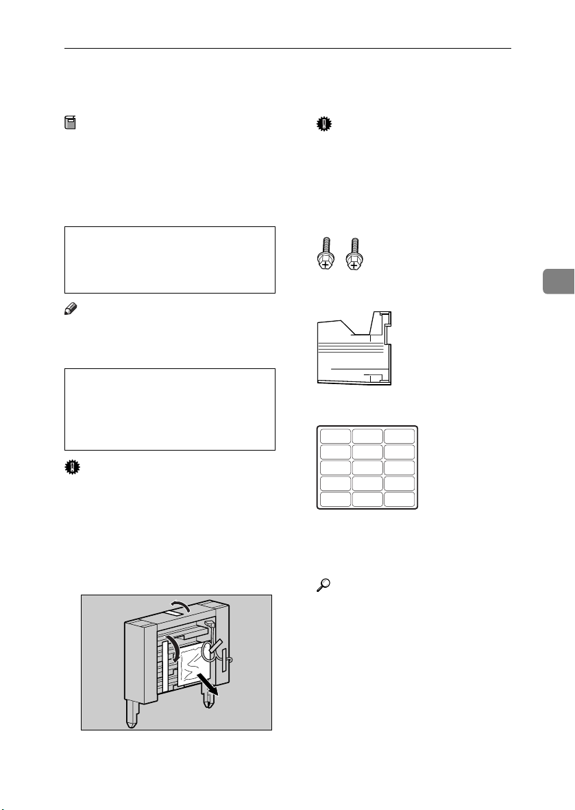
Mail Bin Type 3800C (4-bin Mailbox)
R
R
Mail Bin Type 3800C (4-bin Mailbox)
Preparation
If you want to use the optional paper feed unit at the same time, install the optional paper feed unit
first, and then install the 4-bin
mailbox.
CAUTION:
• When moving the 4-bin mailbox,
hold the center of both sides,
and lift slowly. Lifting carelessly
or dropping it may cause injury.
Note
❒ The 4-bin mailbox weighs approx-
imately 7 kg (15.5 lbs).
CAUTION:
• When installing the 4-bin mailbox, be sure to hold both sides. If
you hold it by the bottom, you
might get your hand caught and
injured.
Important
❒ You cannot install the 4-bin mail-
box and 2 tray finisher at the same
time.
Turn off the power, and then un-
AAAA
plug the power cable.
Remove the attached packaging.
BBBB
Important
❒ Do not remove the adhesive
tape fastening the cable yet. Remove it in step
Check the contents of the box.
CCCC
.
N
❖❖❖❖ Two Screws
❖❖❖❖ Four Output Bins
❖❖❖❖ Labels
>PS< >PS< >PS< >PS< >PS<
>PS< >PS< >PS< >PS< >PS<
>PS< >PS< >PS< >PS< >PS<
Slowly open the front cover of the
DDDD
printer, remove the green screwdriver, and then close the cover.
Reference
p.37 “Using the Screwdriver”
4
ZDJP087J
87
Page 100

Installing Options
Remove the top cover. Draw the
EEEE
lever (AAAA), and then lift (BBBB) to remove it.
Pull up the external tray in the di-
GGGG
rection of the arrow (AAAA), and then
remove (BBBB).
There is an opening for installing
the 4-bin mailbox.
ZDJP777J
4
ZDJP089J
Note
❒ You cannot use the removed
cover.
Holding both sides of the 4-bin
FFFF
If the duplex unit is installed,
HHHH
open the duplex reversal unit.
A Push up the lock release but-
ton, and leave it in that position.
mailbox using both hands, stand
on the left side of the printer.
Slowly lower it into the openings,
and then insert until you hear a
click.
88
ZDJP090J
If the duplex unit is installed, proceed to step
.
H
ZHXH380J
B Slowly lower the duplex re-
versal unit, until it stops.
ZDJP093J
 Loading...