

Page 1
Reissued: 19-Mar-03
T
echnical Bulletin
PAGE: 1/4
Model:
General RTB
Date:
4-Feb-03
No.:
RGene013b
RTB Reissue
The items in bold italics have been corrected or updated.
Subject:
From:
Classification:
Service remarks at installation
Technical Service Sec. Service Planning Dept.
Troubleshooting
Mechanical
Paper path
Other (Specification change)
Prepared by:
Part information
Electrical
Transmit/receive
T. Itoh
Action required
Service manual revision
Retrofit information
Please note the following change in counter specification. Although a production line
modification will not be applied to some products, the action described in 4. Important
Notes for Installation below must be taken for
all products
at installation
.
Overview:
Electronic counters will now be set to 0 when released from the factory, instead of being
set to a negative value.
Background:
Previously, counters were set to a negative value when shipped from the factory, and later
set to “0” at installation, following installation test copies/prints. However this may cause
confusion among some customers as to why the counter value at the commencement of
the contract is “0”, even though some installation test copies have already been made.
Details:
1. Specification Change
Specification
Current
New
• The initial value of the electrical counter is
are shipped from the factory.
Note:
After making test samples at installation, the negative counter
value can be set to “0” with SP mode.
• The initial value of the electrical counter is
shipped from the factory.
Note:
After making test samples at installation, the (positive) counter
value cannot be set back to “0” with SP mode.
negative
“0”
when products
when products are
Page 2
Reissued: 19-Mar-03
T
echnical Bulletin
PAGE: 2/4
Model:
General RTB
Date:
4-Feb-03
No.:
RGene013b
2. Firmware Modification
Due to the counter modification, SP5-849 has also been changed as follows for products
that have this SP mode (listed below).
SP mode name: Specification:
Current Counter Clear
Day
•
When the electrical counter is changed
negative value to 0
, the machine recognizes this
from a
as the counter clear day and stores this date in the
NVRAM.
New Installation Date
• When the electrical counter reaches a value of
20, the machine recognizes this as the installation
date and stores this date in the NVRAM.
NOTE: The following products have SP5-849. The new firmware for these products has
not yet been released. However the release notes for each will clearly mention the
new firmware version.
New products: Bellini-C2, Adonis C3
Current products: Martini C1, Model-U C1
3. Schedule for the Counter Modification
The following is the current schedule for when the counter modification will be applied.
Please note that there are some models to which the change will not be applied (marked
as “---“), due to production schedules, production lot quantities and sales figures.
NOTE: The actual cut-in months that have been confirmed appear in the “Cut-in
production month” column below. This RTB will be reissued when these dates
have been confirmed for the remaining products.
(1) New products
Product Name Product
Code
Bellini C2 B070 2003.03 April ’03 production
Adonis C3 B079/82 2003.03 First mass production lot
Model J-P2 G080 2003.03 March ’03 production
Model J-P2 CF G367 2003.03 March ’03 production
Model AR- P1 G081/92 2003.03 March ’03 production
Model K-C1a B120 2003.03 March ’03 production
Target cut-in
production month
Cut-in production month
Page 3
Reissued: 19-Mar-03
T
echnical Bulletin
PAGE: 3/4
Model:
General RTB
Date:
4-Feb-03
No.:
RGene013b
(2) Current products
Product Name Product
Code
Digital B&W Copiers
Bellini C1 A294 --- --Martini C1 B064/65 2003.03 April ’03 production (see Note)
Model M-C2b B098 2003.03 March ’03 production
Adonis C2 B003/04/06/07 --- --Russian C2 B022/27/31 2003.03 February
Model K-C1 B039/40/43 2003.03 March ’03 production
Stella C1 B044/45/46/49 2003.03 March ’03 production
Digital WF Copiers
Dolphin B010 2003.03 March ’03 production
Analog Copiers
All products - --- --J2SS-C3 B047/48 March ’03 production
Whale A174
Color Copiers
Model I2 B018 --- --Model L2 B017 --- --Model C2 B023 2003.02 February
Model U-C1 B051/52 2003.03 April ’03 production
Color Printers
Model J-P1 G060 --- --Model J-P1 CF G570 --- --Model U-P1 G071 2003.03 March ’03 production
Pomelo P3 G063 2003.03 March ’03 production
Target cut-in
production month
(See Note)
Cut-in production month
’03
production
March ’03 production
’03
production
NOTE: The counter change will be applied as a running change to production units only.
For machines already shipped out or in the field, please be sure to take the action
described below in Section 4.
NOTE: For Martini-C1 mainframes assembled in Japan, the counter change will be
applied from the first unit of April ’03 production. For mainframes assembled
at REI, the change will be applied midway through April production. These
cut-in serial numbers will be announced as soon as they have been
confirmed.
NOTE: The change will also be applied to analog models J2SS-C3 and Whale, as
production will continue for a while. However, as these models use only
mechanical counters, the initial value when shipped from the factory will be
1 or 2 (not 0), following the 1 or 2 factory test copies.
Page 4
Reissued: 19-Mar-03
T
echnical Bulletin
PAGE: 4/4
Model:
4. Important Notes for Machine Installation – All Products
Please be sure to perform the following at machine installation:
1. If the product is from before the counter modification, i.e. the counter is at a negative
2. If the product is modified, i.e. the counter is already at 0 (or above 0 following pre-
3. After completing the installation, make sure to record the counter value. This is very
General RTB
value, be sure to set the counter value to 0 first, then make the installation test
samples.
Digital products Set the electrical counter to 0 with SP mode.
Analog products Set the mechanical counter to 0 with a reset key (tool).
installation at a service depot), simply make the installation test samples.
important, as this value will be used for billing with Meter Click contracts. Also, inform
the customer of the value along with the reason why the counter does not start from
“0”.
Date:
4-Feb-03
No.:
RGene013b
Page 5
T
echnical Bulletin
PAGE: 1/20
Model:
Subject:
From:
Classification:
Model J-P2
Service Manual Revision
1st Tech. Support Sec. Service Support Dept.
Date:
Prepared by:
Troubleshooting
Mechanical
Paper path
Other ( )
Please apply the following revisions
Service Manuals.
Page 1-1
The following has been added:
10°C 80%
Ambient Humidity (% RH)
15°C 30%
10°C 15%
2-Apr-03
Part information
Electrical
Transmit/receive
bold
in
Recommended Conditions:
, as well as additions and deletions to your
15 to 25 °C
30 to 70 %RH
27°C 80%
25°C 70%
32°C 54%
32°C 15%
No.:
H.Taguchi
Action required
Service manual revision
Retrofit information
RG080001
Ambient Temperature (°C)
Page 6
T
echnical Bulletin
PAGE: 2/20
Model:
Model J-P2
Date:
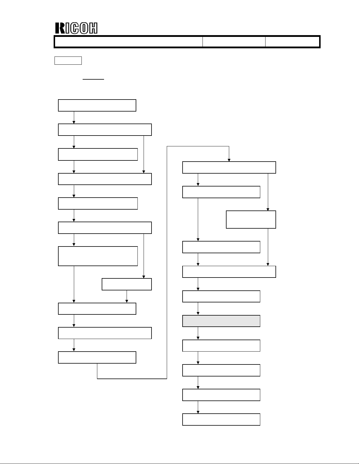
Page 1-7
Contents revised
: The following bold word was deleted from the flowchart illustration.
Clear the memory of IPU/Netfile/Scanner (SP-5-801-10,12) ].
1. Place the printer on the PFU or LCT.
2. Install the PFU or LCT.
Unpack the printer.
Will the paper feed unit (PFU) or LCT be
installed?
Install the controller options (if required).
Install the duplex unit (if required).
Will the two-tray finisher be installed?
Yes
Install the punch unit (if required).
2-Apr-03
No.:
RG080001
No
Will the rack be installed?
Yes
1. Install the printer.
2. Assemble the rack during printer
initialaization
Install the printer
Dock the printer and rack.
Install the CF expander.
Install the platen cover or ARDF.
Install the m ulti-bin
output tray (if required).
No
Install the two-tray finisher.
Select the language.
Set the date and time.
Clear the memory of IPU/Scanner.
(SP5-801-10, 12)
Perform ACC.
Check magnification and registration.
Adjust the operation panel display if
Set the meter charge mode depending
necessary.
on the service contract.
Page 7
T
echnical Bulletin
PAGE: 3/20
Model:
Page 1-24
Page 1-25
Page 1-32
Model J-P2
Accessories Check List
7. DIMM #1 (
8. DIMM #2 (
2. Replace the printer module [A] in the upper slot with DIMM #1 (
3. Insert DIMM #2 (
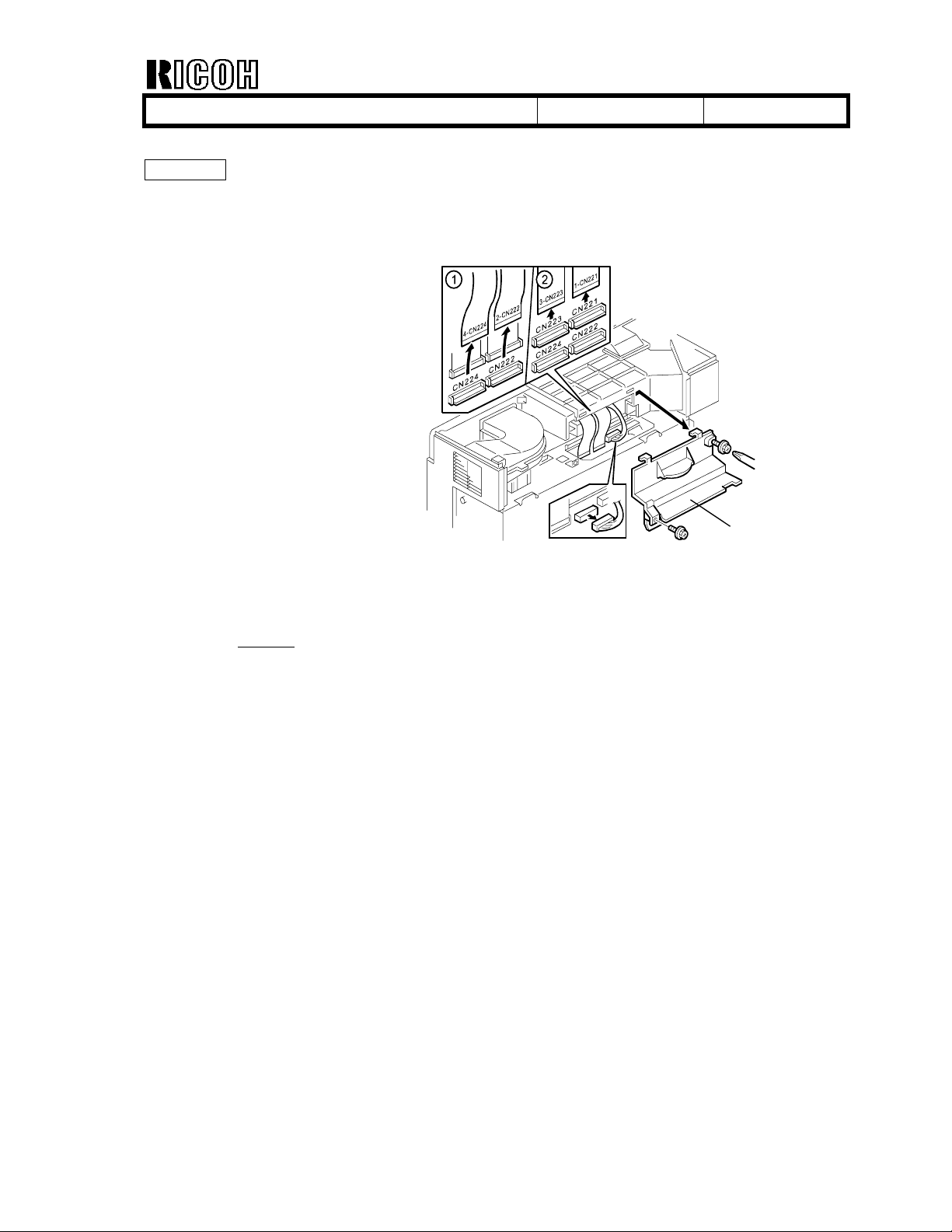
A harness clamp [C] and harness core have been added, and the harness attachment
has been revised as follows.
Date:
SYSTEM/PRT
SCN
) ......................................................... 1
SCN
) [C] into the center slot.
) .......................................... 1
2-Apr-03
No.:
SYSTEM/PRT
RG080001
) [B].
[C]
[B]
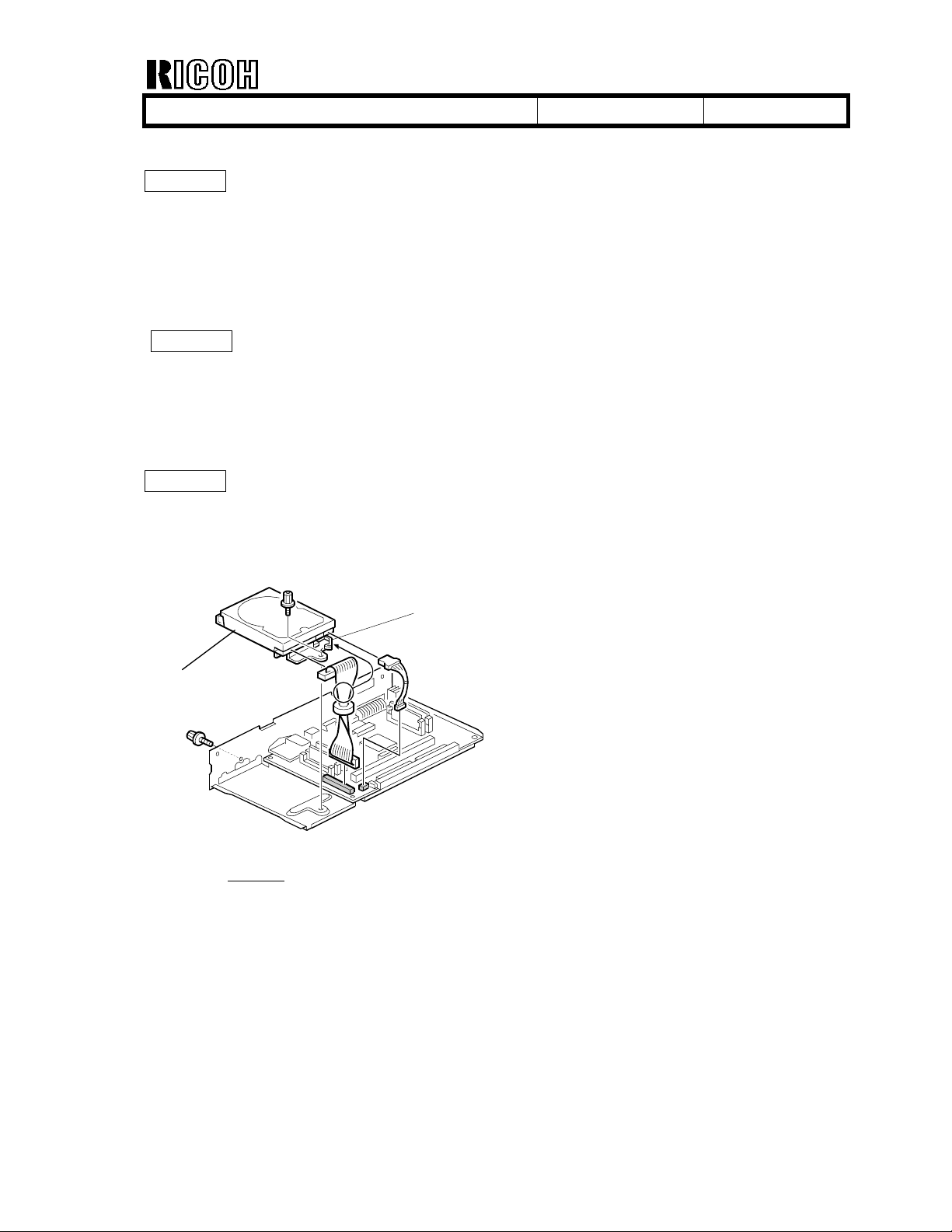
- Step 2 revised
2. Mount the 40GB HDD [B] on the controller (Harness x 2, Screw x 2,
as follows:
Clamp[C] x 1
)
Page 8
T
echnical Bulletin
PAGE: 4/20
Model:
Page 3-10
- A screw has been added and the shape of the connector cover has been changed as
follows.
!!!!!!!!!!!!!!!
!
!
!!!
- Step 12 revised
12. Connector cover [E] (Screw x 2)
!
Model J-P2
Date:
as follows:
!
2-Apr-03
No.:
RG080001
[E]
!
Page 9
T
echnical Bulletin
PAGE: 5/20
Model:
Model J-P2
Date:
2-Apr-03
No.:
RG080001
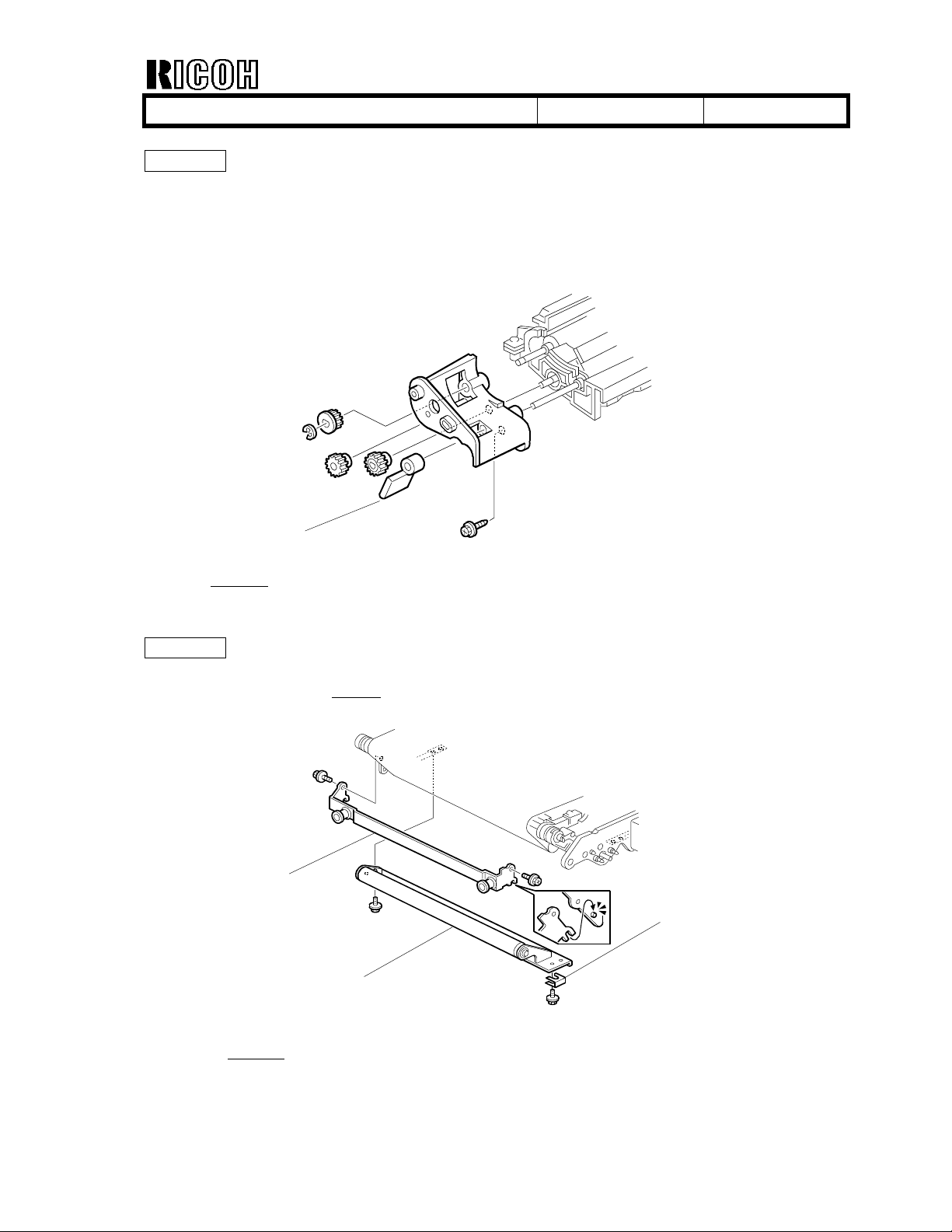
Page 3-23
- The screw which stops the lever has been deleted, and the shape of the lever has been
changed as follows.
Lever
G080R741.WMF
- Step 4 deleted
.
4. Lever [C] (Screw x 1)
Page 3-25
- A spacer [E] has been added
[C]
[D]
- Step 6 revised
as follows.
6. Tension roller [D] (
.
Spacer [E] x 1
[E]
G080R745.WMF
, Screw x 2)
Page 10
T
echnical Bulletin
PAGE: 6/20
Model:
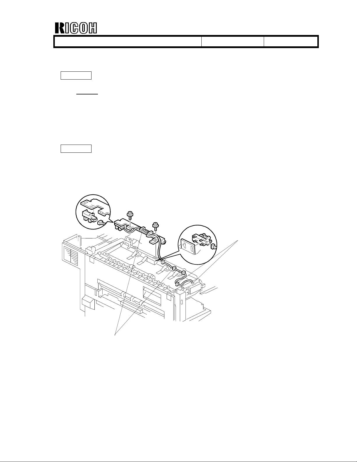
Page 3-26
Note deleted
Page 3-42
Model J-P2
NOTE: 1)
- Four clamps [D] have been added, and the attachment of the harness has been
changed as follows. The clamp at the right-hand end is not visible in the drawing.
Date:
:
If the transfer charge brushes are dirty, clean them with a vacuum
cleaner.
2-Apr-03
No.:
RG080001
[D]
[D]
Page 11
T
echnical Bulletin
PAGE: 7/20
Model:
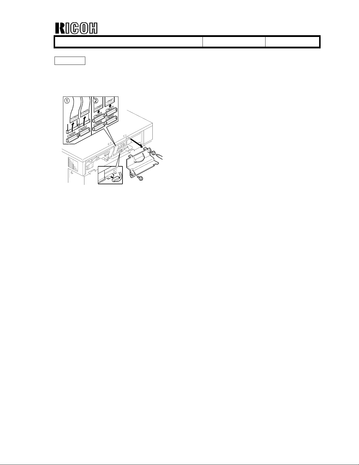
Page 3-43
- A screw has been added, and the shape of the connector cover has been changed as
follows.
- Step 4 revised.
Model J-P2
Date:
4. Connector cover [E] (Screw x 2)
2-Apr-03
No.:
RG080001
Page 12
T
echnical Bulletin
PAGE: 8/20
Model:
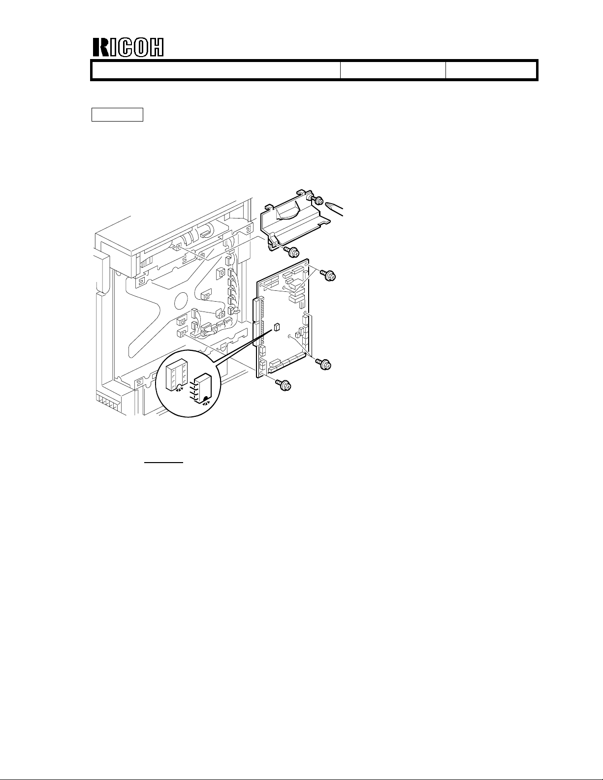
Page 3-45
- A screw has been added and the shape of the connector cover has been changed as
follows.
Model J-P2
Date:
2-Apr-03
No.:
RG080001
- Step 6 revised.
6. Connector cover [E] (Screw x 2)
Page 13

T
echnical Bulletin
PAGE: 9/20
Model:
Page 3-50
- A retaining ring [B] has been inserted between the magnetic clutch and the bushing, as
follows.
- Step 3 revised.
Model J-P2
3. Development clutch [A] (Connector x 1, Screw x 1, Retaining ring [B] x 1)
Date:
[B]
2-Apr-03
No.:
RG080001
Page 14

T
echnical Bulletin
PAGE: 10/20
Model:
Model J-P2
Page 4-19
SC
No.
SC
392001
Item Definition
Air
pump
motor
error
392
001:
MY
392
002:
CK
Page 4-24
SC
543
Heating
roller
fusing
lamp
overheat
Page 4-25
SC
Heating
roller fusing
544
lamp high
temperature
error
SC
552
Pressure
roller
warm-up
error
SC
553
Pressure
roller
fusing
lamp
overheat
Date:
Three consecutive
errors are detected
in motor-driversignal samples.
The samples are
collected every
0.01 second.
The detected fusing
temperature stays at
210
°C or more for
five seconds.
During stand-by
mode or a print job,
the detected heating
roller temperature
stays at 210 °C or
more for
After the main switch
is turned on or the
door is closed, the
pressure roller
temperature does not
reach the ready
temperature within
180 seconds during
fusing unit warm-up.
The detected
pressure roller
temperature stays at
210
five seconds.
0.2
second.
°C or more for
Possible
Cause
•
Damaged
cable
•
Short circuit
•
Defective
motor
• Defective PSU
• Defective
BCU
•
• Defective
• Defective
• Pressure roller
fusing lamp
broken
•
Defective
pressure roller
thermistor
• Defective
BCU
•
Defective PSU
•
Defective
BCU
Defective
heating roller
thermistor
PSU
BCU
Related
SCs
1. Turn the main switch off and
2-Apr-03
Troubleshooting Procedure Type
on.
2. Replace the air pump.
3. Check the circuit.
1. Replace the PSU.
1. Replace the fusing unit.
1. Check if the pressure
1. Replace the fusing unit.
No.:
2. Replace the BCU.
2. Replace the PSU.
3. Replace the BCU.
roller thermistor is firmly
connected.
2. Replace the fusing unit.
3. Replace the BCU.
2. Replace the PSU.
3. Replace the BCU.
RG080001
A
A
A
A
Page 15

T
echnical Bulletin
PAGE: 11/20
Model:
Model J-P2
Date:
Page 4-26
SC Code deleted
:
SC
554
Pressure
roller fusing
lamp low
temperature
error
During stand-by
mode or printing, the
detected pressure
roller temperature
stays at 50°C or less
for five seconds.
Page 4-27
SC
BCU Controller
640
communication
error (check
sum error)
Page 4-30
SC description added
SC
GAPCI I2C
communication
692
error
The check sum of
the interface
between the BCU
and controller is not
the same.
:
• The I2C bus
device ID is not
identified during
initialization.
•
A device-status
error occurs
during I2C bus
communication.
• The I2C bus
communication is
not established
due to an error
other than a buffer
shortage.
•
Loose
connection
between the
fusing unit
and the
machine
• Defective
pressure roller
thermistor
• Defective
PSU
•
Defective
BCU
• Defective
controller
•
Defective
BCU
• Loose
connection
• Defective
BCU
• Defective LD
controller
board
2-Apr-03
1. Check the connection
1. Turn the main switch off
1. Turn the main switch off
No.:
between the fusing unit
and main frame.
2. Replace the fusing unit.
3. Replace the PSU.
4. Replace the BCU.
and on.
2. Replace the controller.
3. Replace the BCU.
and on.
2. Check the cable
connection.
3. Replace the BCU.
RG080001
A
CTL
A
Page 16

T
echnical Bulletin
PAGE: 12/20
Model:
Model J-P2
Date:
Page 4-34
SC descriptions added
SC
800
SC
801
SC
802
SC
803
Startup
without
video
output end
error (K)
Startup
without
video
output end
error (Y)
Startup
without
video
output end
error (M)
Startup
without
video
output end
error (C)
Video transfer to the
engine is started, but
the engine did not
issue a video
transmission end
command within the
specified time.
Video transfer to the
engine is started, but
the engine did not
issue a video
transmission end
command within the
specified time.
Video transfer to the
engine is started, but
the engine did not
issue a video
transmission end
command within the
specified time.
Video transfer to the
engine is started, but
the engine did not
issue a video
transmission end
command within the
specified time.
Page 4-37
Contents revised:
SC
827
[0201]
Verification
error
Self-diagnostic error: Standard
Error detected during
a write/verify check
for the standard RAM
SDRAM
(
:
DIMM).
•
Defective
BCU
•
Defective
BCU
• Defective
BCU
•
Defective
BCU
SDRAM
• Loose
connection
• Defective
SDRAM
DIMM
•
Defective
controller
2-Apr-03
1. Turn the main switch off
1. Turn the main switch off
1. Turn the main switch off
1. Turn the main switch off
DIMM [XXXX]: Detailed error code
1. Turn the main switch off
No.:
and on.
2. Check the cable
connection.
3. Replace the BCU.
and on.
2. Check the cable
connection.
3. Replace the BCU.
and on.
2. Check the cable
connection.
3. Replace the BCU.
and on.
2. Check the cable
connection.
3. Replace the BCU.
and on.
2. Replace the
DIMM.
3. Replace the controller.
RG080001
SDRAM
CTL
CTL
CTL
CTL
CTL
Page 17

T
echnical Bulletin
PAGE: 13/20
Model:
Model J-P2
Date:
Page 4-39
SC
857
USB
interface
error
The USB interface
cannot be used due
to a driver error.
Page 4-40
SC description added:
SC
991
Software
continuity
error
The software attempted to perform
an unexpected operation.
However, unlike SC990, the cause
of the error is continuity of the
software.
•
Defective USB
driver
• Loose
connection
2-Apr-03
1. Check the connection.
No.:
2. Replace the USB board.
RG080001
• Software error
• Internal
parameter
incorrect,
insufficient
working memory.
This SC is not
displayed on the
LCD (log only).
CTL
Page 18

T
echnical Bulletin
PAGE: 14/20
Model:
Model J-P2
Page 5-14
Contents revised:
1
[
Fusing Cont.] Fusing Control
104
1 Control Method *BCU Selects the fusing control method.
25 Process Speed *BCU Selects the power-on default target fusing
(Class 1, 2, and 3)
Date:
2-Apr-03
No.:
RG080001
Mode No.
[ 0 or 1 / 0
0: ON/OFF Control
1: Phase Control
NOTE: This mode can be used only for N.
America models.
operation temperature.
The target operating fusing temperature depends
on the process speed. When the machine is
switched on, it starts warming up for the process
speed specified in this SP mode.
[0 to 4 / 4
0: Color 62.5 mm/s (temperature specified by SP
1-105-8 and 19)
1: Color 125 mm/s (temperature specified by SP
1-105-9 and 20)
2: Thick / OHP (temperature specified by SP 1105-13 and 24)
3: K 125 mm/s (temperature specified by SP 1105-4 and 15)
4: K 185 mm/s (temperature specified by SP 1105-5 and 16)
Function / [ Setting ]
/ - ] Alphanumeric
/ 1/step] Alphanumeric
Page 19

T
echnical Bulletin
PAGE: 15/20
Model:
Model J-P2
Page 5-15
1
[Fusing Temp.] Fusing Temperature
105
(Heating or Pressure roller: Paper Type, [Color], Simplex/Duplex, Process Speed)
Paper Type -> N: Normal, OHP. TH: Thick, SP: Special
Some settings of fusing temperature depend on the destination (US or Europe/Asia).
US: Setting for US, EU: Setting for Europe/Asia
1 H: Ready *BCU Sets the heating roller temperature for the printing
2 P: Ready *BCU Sets the pressure roller temperature for the
The following SPs set the target operating temperatures of the heating and pressure
rollers in various modes. (The default settings are different for N. America and Eur./Asia)
4 H:N [K] S 125 *BCU
5 H:N [K] S 185 *BCU
6 H:N [K] D 125 *BCU
7 H:N [K] D 185 *BCU
8 H:N[FC] S 62.5 *BCU
9 H:N[FC] S 125 *BCU
10 H:N[FC] D 62.5 *BCU
11 H:N[FC] D 125 *BCU
1 3 H :O H P *BCU
15 P:N [K] S 125 *BCU
16 P:N [K] S 185 *BCU
17 P:N [K] D 125 *BCU
18 P:N [K] D 185 *BCU
19 P:N[FC] S 62.5 *BCU
20 P:N[FC] S 125 *BCU
21 P:N[FC] D 62.5 *BCU
22 P:N[FC] D 125 *BCU
2 4 P :O H P *BCU
2 6 H :T H *BCU
Date:
Mode No.
(Class 1, 2, and 3)
ready condition.
After the main switch has been turned on, the
machine enters the print ready condition when the
heating roller temperature reaches the
temperature specified in this SP mode.
When the machine is in the recovery mode from
the energy saver or auto off mode, the machine
becomes ready when both heating and pressure
roller temperatures reach the specified
temperature.
Ready temperature = (Target temperature
specified in SP1-104-25 or 105-3 to 28) –
Temperature specified in this SP mode.
[ 10 to 100 / 10
printing ready condition.
Ready temperature = (Target temperature
specified in SP1-104-25 or 105-3 to 28) –
Temperature specified in this SP mode
[ 10 to 100 / NA: 10
[ 100 to 190 / NA:
/
[ 100 to 190 /
[ 100 to 190 /
[ 100 to 190 /
[ 100 to 190 / NA: 150
[ 100 to 190 / 180
[ 100 to 190 / NA:
[ 100 to 190 / NA:
[ 100 to 190 / 165
[ 0 to 190 / NA: 160
[ 0 to 190 / NA:
[ 0 to 190 / NA: 135
[ 0 to 190 / NA: 145, EU: 155 / 5°C/step]
[ 0 to 190 / NA: 125
[ 0 to 190 / 160
[ 0 to 190 / NA: 120, EU: 125 / 5°C/step]
[ 0 to 190 / NA: 135
[ 0 to 190 / 150 / 5°C/step]
[ 0 to 190 / 175
NA: 165
NA: 175
2-Apr-03
Function / [ Setting ]
/ 1oC/step ]
, EU: 20 / 1oC/step ]
180
, EU: 175 / 5°C/step]
NA: 185, EU: 180
, EU: 165 / 5°C/step]
, EU: 175
, EU: 150 / 5°C/step]
/ 5°C/step]
145
, EU: 145/ 5°C/step]
165
, EU: 170 / 5°C/step]
/ 5°C/step]
, EU: 155 / 5°C/step]
155
, EU: 160 / 5°C/step]
, EU: 145 / 5°C/step]
, EU: 130 / 5°C/step]
/ 5°C/step]
, EU: 150 / 5°C/step]
/ 5°C/step]
No.:
/ 5°C/step]
RG080001
/ 5°C/step]
Page 20

T
echnical Bulletin
PAGE: 16/20
Model:
Model J-P2
Date:
2-Apr-03
No.:
Page 5-32
3
107 4 LED Current C *BCU Displays the ID sensor LED current adjusted
Mode No.
(Class 1, 2, and 3)
Function / [ Setting ]
during Vsg adjustment.
1023
[ 0 to
/ - / 1 ]
Page 5-33
3
6 LED Current R *BCU Displays the ID sensor LED current adjusted
107
7 Vsg avg bk *BCU Displays the average black Vsg value of the
Mode No.
(Class 1, 2, and 3)
Function / [ Setting ]
during Vsg adjustment.
1023
[ 0 to
center ID sensor.
[ 0.00 to 5.00 / - / 0.01V/step ]
/ - / 1 ]
Page 5-46
Contents revised
:
5
[
Simplex Back Sheet Setting]
118
1 Simple Back Sheet
Setting
Mode No.
(Class 1, 2, and 3)
Function / [ Setting ]
*CTL Enables or disables all machine functions.
[ 0 or 1 / 0
0: Enabled
1: Disabled
/ - ] DFU
RG080001
Page 21

T
echnical Bulletin
PAGE: 17/20
Model:
Model J-P2
Date:
2-Apr-03
No.:
RG080001
Page 5-97
Contents revised
:
Type of firmware Function
Printer Engine
Printer Controller
1. Main Printer engine control 1 card
2. MUSIC Line position adjustment 1 card
3. DSP Line position adjustment 1 card
4. System System firmware 1 card
5. Printer Printer Application
firmware
6. NIB
NIB firmware 1 card
Number of IC cards
required
1 card
Page 5-99
Contents revised
:
Type of firmware Function
* Engine - Main Printer engine control BCU Flash ROM Engine (1)
* Engine - Music Line position adjustment BCU MUSIC CPU Music (1)
* Engine - DSP Line position adjustment BCU DSP CPU DSP (1)
•
System
• Netfile Application
Copier Application Feature application DIMM 1 Rescue & Copy (1)
Printer Application Feature application DIMM 1 Onboard Printer (1)
Scanner Application Feature application DIMM 2 Onboard Scn (1)
Fax Application Feature application DIMM 2 Opt DIMM Fax (1)
NIB (see Notes)
Scanner IPU Scanner control IPU Flash ROM Scanner IPU (1)
Operation Panel Panel control Operation Panel Ope Panel. XX (1)
Fax FCU Fax control FCU Jupi FCU (XXX)-1 (1)
Language
(16 languages)
2 different firmware (system
and Netfile applications) is
combined.
Network Interface DIMM 2 Network Support (1)
Language firmware
Two languages can be
selected from 16
languages.
Location of
firmware
DIMM 1
Operation Panel
Message displayed
Onboard System (1)
Netfile DocBox (2)
LANG.1 (1)
LANG.2 (2)
Note: The NIB used in the CF is different from the one used in the printer.
Page 22

T
echnical Bulletin
PAGE: 18/20
Model:
Model J-P2
Page 6-42
- Illustration revised
1.Doctor blade
Date:
2-Apr-03
No.:
RG080001
to show correct parts:
1
2
3
6
Page 6-67
Contents revised
:
Mode Resolution (dpi)
Energy saver
level 1
Standby mode
Color
Black and white
OHP All
Thick All
1200 x 1200
1200 x 600
600 x 600
1200 x 1200
1200 x 600
600 x 600
Temperature of
Heating Roller
100°C 130°C
NA: 175
EU: 170
150°C
180°°°°C 160°°°°C
NA: 180°°°°C
EU: 175
NA: 185°°°°C
EU: 180°°°°C
165°C 150°C
175°C 155°C
5
°°°°
°°°°
°°°°
C
C
C
4
Temperature of
Pressure Roller
NA: 145
EU: 140
NA: 125°C
EU: 130°C
NA: 160°°°°C
EU: 155
NA: 155°°°°C
EU: 160°°°°C
C
°°°°
C
°°°°
C
°°°°
G080D953.WMF
Note
If SP1-104025 is set to 4
Page 23

T
echnical Bulletin
PAGE: 19/20
Model:
Color
(duplex)
Black and white
(duplex)
Model J-P2
Date:
1200 x 1200
1200 x 600
600 x 600
1200 x 1200
1200 x 600
600 x 600
145°C
NA: 165°C
EU: 170°C
165°C
175°C
2-Apr-03
NA: 120°C
EU: 125°C
NA: 135°C
EU: 150°C
NA: 135°C
EU: 145°C
NA: 145°C
EU: 155°C
No.:
RG080001
Page 6-68
Overheat Protection
If the heating or pressure roller temperature becomes higher than
210
°C, the CPU cuts
off the power to the fusing lamp. SC543 for the heating roller or SC553 for the pressure
roller is generated.
Page 6-89
Partition 40GB HDD 20GB HDD Function Comment
Image Local
Storage
File System 1 500 MB 500 MB
File System 2 1,000 MB 1,000 MB Job spooling area Erased after power off.
File System 3 2,000 MB 2,000 MB Work data area
Image TMP
Job Log 10 MB 10 MB Job log
17,700 MB --- Document server
Downloaded fonts,
forms.
7,486 MB 7,486 MB
7,200 MB --- Copier application Erased after power off.
3,440 MB 3,440 MB Printer application Erased after power off.
1,000 MB
1000MB
Commonly used area
for applications
Scanner application Erased after power off.
Remains stored even
after cycling power
off/on.
Remains stored even
after cycling power
off/on.
Remains stored even
after cycling power
off/on.
Erased after power off.
Remains stored even
after cycling power
off/on.
Page 6-103
Item in bold deleted:
Data rates: 480 Mbps (high speed), 12 Mbps (full speed), 1.5 Mbps (low speed);
High-speed mode is only supported by USB 2.0.
Page 24

T
echnical Bulletin
PAGE: 20/20
Model:
Model J-P2
Date:
SPEC-2
Contents revised:
Maximum 1200 W or less
Energy Saver
120V
1500 W or less
15 W or less 15 W or less
SPEC-7
Internal Options
IEEE802.11b
USB2.0 B525 L
G628 K
SPEC-12
Power source:
System:
120 V, 60 Hz: 12 A (for North America)
220 - 240 V, 50/60 Hz:
6A+1A
Scanner:
120 V, 60 Hz: 2 A (for North America)
220 - 240 V, 50/60 Hz: 1.1 A (for Europe/Asia)
Maximum power
System: 1,440 W or less
2-Apr-03
220~240V
(for Europe/Asia)
(NA)
No.:
RG080001
1,500W+120W or less (EU)
Page 25

T
echnical Bulletin
PAGE: 1/3
Model:
Subject:
From:
Classification:
Model J-P2
Wrong resolution printing with PS3 driver
1st Tech. Support Sec. Service Support Dept.
Date:
Troubleshooting
Mechanical
Paper path
Other ( )
24-Apr-03
Prepared by:
No.:
H. Someya
RG080002
Part information
Electrical
Transmit/receive
Action required
Service manual revision
Retrofit information
SYMPTOM
Jobs specified in the PS driver as 600dpi Fast (600x600dpi, 1 bit), or 1200dpi
(1200x1200dpi, 1 bit) are printed out at the wrong resolution when:
1) Printing from a PS driver, except those for Win9x/Me, and
2) The mainframe PS menu resolution is set to "600dpi Std" (default).
The following are the test results with various combinations of resolution settings from the
PS driver and mainframe PS menu:
Resolution setting in PS
driver:
600dpi Fast
(600x600dpi 1 bit)
600dpi Fast: Default
(600x600dpi, 1 bit)
600dpi Std
(600x600dpi, 2 bit)
1200dpi
(1200x1200dpi, 1 bit)
None specified
(driver not used)
600x600dpi
1200x600dpi 1200x600dpi 1200x600dpi
1200x1200dpi 600x600dpi
600x600dpi 1200x600dpi 1200x1200dpi
Resolution setting in mainframe PS menu:
600dpi Std: Default
(600x600dpi 2 bit)
1200x600dpi
NG
NG
(1200x1200dpi 1 bit)
1200dpi
600x600dpi
1200x1200dpi
CAUSE
The commands for resolution and grayscale (number of bits) are sent by the PS driver and
received by the machine. However, when the machine is set for 2-bit grayscale, it is not
overwritten by the 1-bit grayscale setting from the driver (normally the driver is given
precedence).
Note:
This does not occur with Win9x/Me drivers since the grayscale bit setting is
specified with PJL commands.
Page 26

T
echnical Bulletin
PAGE: 2/3
Model:
Model J-P2
Date:
24-Apr-03
No.:
RG080002
Affected firmware versions:
J-P2: Printer 1.09 (used from 1st production)
J-P2CF: Printer 1.09 (used from 1st production)
Affected S/N:
See the S/N table below.
SOLUTION
Production
1) Modify the Printer firmware (scheduled to be applied from the end of March ‘03).
2) Modify all PS drivers except those for Win9x/Me (schedule TBA).
Note:
Although from a technical standpoint only one of the above is necessary to fix the
symptom, both will be applied in order to perform the action in the field described
below.
Action in the field
Please take the following action for all machines within the S/N range listed below.
1. For machines installed by service technicians, please do one of the following at
installation:
1) Change the PS Menu resolution setting (UP mode) to "
2) Update the printer firmware to v1.12 or later.
2. For user-installed machines, please advise any customers reporting the symptom to
do one of the following:
1) Change the PS menu resolution setting (UP mode) to "
2) Install one of the modified PS drivers accessible on the Web.
Web release schedule for modified PS drivers:
Without MS logo: Already released
With MS logo: May 2, 2003
600dpi Fast
600dpi Fast
", or
,” or
Page 27

T
echnical Bulletin
PAGE: 3/3
Model:
Model J-P2
Date:
24-Apr-03
No.:
RG080002
Affected serial number table:
Model Code Serial Number
G080-22 P9630201479 – 1537, 1539 – 1558, 1560 – 1688, 1690 – 1718, 1720 – 1745, 2473 –
2594,
P9630301111 – 1138, 1140 – 1174, 1176 – 1202, 1204 – 1268, 1270 – 1283, 1285
G080-24 L1403020002 – 0007, 0009 – 0032, 0034 – 0037, 0039 – 0100
G080-26 8Q40230001 – 0003, 0005 – 0048, 0050 – 0073, 0075 – 0078, 0080 - 0100
G080-27 P9630100042 – 000048, 0050 – 0054, 0056 – 0060, 0062 – 0080,
P9630201746 – 1755, 1757 – 1766, 1768 – 1793, 1795 – 1808, 1810 – 1867, 1870–
1940, 1942 – 2081, 2083 – 2105, 2107 – 2141, 2143 – 2187, 2189 – 2212, 2214 –
2216, 2218 – 2249, 2251 – 2262, 2264 - 2265, 2267 – 2285, 2287 – 2311, 2313 –
2365,
P9630301531, 1533 – 1534, 1536 – 1539, 1541, 1543 – 1546, 1549, 1551 – 1555,
1557 – 1563, 1566, 1569, 1572, 1575, 1577, 1581 – 1582, 1587, 1597 – 1598, 1601,
1606 – 1607, 1610, 1613, 1615, 1619 – 1636, 1638 – 1655, 1657 – 1674, 1676 – 1685,
1687 – 1691, 1693 – 1719, 1721 – 1739, 1741 – 1742, 1744 – 1751, 1754, 1756 –
1761, 1764, 1766 – 1769, 1771 – 1775, 1777, 1779 – 1782, 1784 – 1793, 1795 – 1801,
1804 – 1807, 1809 – 1820, 1823 – 1825, 1827, 1829, 1831 – 1832, 1834, 1836 – 1838,
1840, 1844 – 1845, 1847, 1852, 1855, 1861, 1872 – 1873, 1877, 1885, 1904, 1906,
1920, 1924
G080-29 P9630202366 – 2384, 2386 – 2412, 2414 – 2422, 2424, 2426 – 2427, 2429 – 2433,
2435 – 2445, 2447 – 2455, 2457 – 2467, 2469 - 2471
G367-26 8Q50230001 – 0040
8Q50330001 – 0050
G367-27 P9830100021, 0023 – 0040,
P9830200796 – 0903,0905 – 1230, 1280 – 1324,
P9830300881 – 0918, 0920 – 1045, 1047 - 1070
G367-29 P9830201231 – 1279,
P9830301470, 1473 - 1482
Page 28

T
echnical Bulletin
PAGE: 1/4
Model:
Subject:
From:
Classification:
Model J-P2
Firmware Modification
1st Tech. Support Sec. Service Support Dept.
Date:
Prepared by:
Troubleshooting
Mechanical
Paper path
Other ( )
25-Apr-03
Part information
Electrical
Transmit/receive
No.:
H.Someya
Action required
Service manual revision
Retrofit information
RG080003
Firmware modification history for the Model J-P2 (details begin on page 2).
Engine Controller
Firmware
Type
Remarks
Main MUSIC DSP Printer
System
Application
Printer
Printer NIB
Note:
The Engine Main, Music and DSP firmware are used for both the G080 printer and
the G080/G367 CF Expander.
RTB Revision List
Issue Date Control Symbol Revised contents
25-Apr-03 - First edition
Page 29

T
echnical Bulletin
PAGE: 2/4
Model:
Model J-P2 Date: 25-Apr-03 No.: RG080003
[ Modification History ]
1. Engine Main Firmware
P/N Version Check
Sum
G0805601D 1.03 --- Firmware installed from the first mass production run. January, 03
G0805601E 1.04 DEDF The following have been fixed.
• SC544. Fusing control changed so that the machine rotates the fusing belt if the fusing
temperature is 200°C or greater when the main power is turned on or the machine recovers
from Energy Saver Mode (stopping when the temperature cools to 190°C).
•
SC552 (detection time lengthened from 150s to 180s).
G0805601F 1.05 FA42
G0805601G 1.06 40B9 The following have been fixed.
• Key card interface supported as a customized request. To activate this function, it is necessary
to use CF system firmware
•
The following have been fixed.
! Default settings for transfer bias changed to fix fireflies in black solid image areas on
OHP sheets under high-temperature and humidity conditions.
! Main scan color shift caused by electromagnetic noise.
• "Copying" displayed for about 30 seconds before copying begins.
• Color drum lock at first color print following a 3-hour interval when energy saver is disabled.
• Paper jam following jam recovery if the duplex copy output tray is set to the Finisher.
• Copying is halted if the number of copies on the key card reaches 0 or the key card is pulled
out during duplex copying and finisher output selected with SP5-113 is set to 12 (Exp. Key
Card: Deduct). After a new key card is inserted, a jam occurs at the finisher.
Contents of Modification Cut-in Month
February, 03
April, 03
v1.12
or newer.
April 14, 03
NOTE: Machines containing v1.03 have been reworked locally.
Page 30

T
echnical Bulletin
PAGE: 3/4
Model:
Model J-P2 Date: 25-Apr-03 No.: RG080003
2. Engine MUSIC
P/N Version Check
Sum
G0805611B M1.01 4EBC Firmware installed from the first mass production run. January, 03
Contents of Modification Cut-in Month
3. Engine DSP
P/N Version Check
Sum
G0805621B 1.01 8DFE Firmware installed from the first mass production run. January, 03
Contents of Modification Cut-in Month
4. Printer System Firmware
P/N Version Check
Sum
G0805910B 1.09 --- Firmware installed from the first mass production run. January, 03
G0805910C 1.11 7B3D The Wireless LAN does not function if using 802.11adhoc mode when network traffic is low. February, 03
G0805910D 1.12 99B9 The Printer function is now displayed on the configuration page.
Contents of Modification Cut-in Month
April, 03
NOTE: Machines containing v1.09 have been reworked locally.
Page 31

T
echnical Bulletin
PAGE: 4/4
Model:
Model J-P2 Date: 25-Apr-03 No.: RG080003
5. Printer Application Firmware
P/N Version Check
Sum
G0805911B 1.09 --- Firmware installed from the first mass production run. January, 03
G0805911C 1.12 4754 The following have been fixed.
- Barcodes appear separated (shifted) when printed out (GFPR#RE03010016).
- Downloaded PCL Barcode fonts are not printed correctly on the PCL font list
(GFPR#RC03010004).
- PS error occurs when unknown media type is specified (GFPR# RE03010003).
- Selecting HDD font or DIMM font may reduce available memory.
- Supports SAP Barcode & OCR printing.
Other changes:
- The default for the mainframe PS Menu resolution setting has been changed to “600dpi Fast”,
because the resolution setting in the PS driver is not recognized when the mainframe setting is
600dpi Std.
NOTE:
When updating the Printer Application Firmware, please also update the Printer System Firmware to the same version.
Contents of Modification Cut-in Month
April, 03
4. NIB Firmware
P/N Version Check
Sum
G0805920C 3.0.1 1CC3 Firmware installed from the first mass production run. January, 03
Contents of Modification Cut-in Month
Page 32

Reissued: 9-May-03
T
echnical Bulletin
PAGE: 1/3
Model:
Model J-P2
Date:
2-May-03
No.:
RG080004a
RTB Reissue
The items in bold italics have been corrected.
Subject:
From:
Noise from paper transfer section
1st Tech. Support Sec. Service Support Dept.
Classification:
Troubleshooting
Mechanical
Paper path
Other ( )
Prepared by:
H.Someya
Part information
Electrical
Transmit/receive
Action required
Service manual revision
Retrofit information
SYMPTOM
Noise from the paper transfer-cleaning unit.
CAUSE
The edge of the cleaning unit [C] bends slightly during operation, causing the gap between
it and the left lower driver roller [B] (#G0803945, P/C 41-7) to narrow and the unit to
contact the roller.
[B]
[A]
[C]
SOLUTION
Action required in the field:
At installation or the next service visit, please check to see if noise can be heard from the
paper transfer cleaning unit. If there is noise, file down the edge of the cleaning unit case
as described in the
Troubleshooting Procedure
below.
Page 33

Reissued: 9-May-03
T
echnical Bulletin
PAGE: 2/3
Model:
Production line
! Temporary:
Cut-in S/N
G080-17: From P9630400341
G080-22: From P9630401761
G080-24: From L1403040001
G080-26: From 8Q40430001
G080-27: From P9630402580
G080-29: From P9630402955
! Permanent:
Model J-P2
The edge of the cleaning unit case has been filed down 1.5 mm using a special tool to
ensure enough of a gap between the cleaning unit case and the roller.
NOTE:
in S/N below), and has already been applied to all service parts (#G0803830 and
#G0803831).
The shape of the cleaning unit case will be modified to prevent contact with the roller.
This temporary solution was applied to the production line on April 4, 2003 (cut-
Date:
2-May-03
No.:
RG080004a
Troubleshooting Procedure
1. Turn off the main switch.
2. Open the front cover and pull out the paper transfer unit (1 screw).
3. Remove the cleaning unit, holding the cleaning blade release lever (1 screw).
4. Place the cleaning unit onto a sheet of paper, as shown below.
5. Using the blunt side of a box cutter or metal ruler, file down the edge [A] of the
cleaning unit case, from front to rear, by approximately 1.5 mm (0.06 in.).
[A]
Page 34

Reissued: 9-May-03
T
echnical Bulletin
PAGE: 3/3
Model:
NOTE: Make sure to prevent any plastic particles from getting inside the cleaning unit, e.g.
NOTE: If the rear side of the output already shows the dirty lines, and the roller, cleaning
Model J-P2
by covering the open space [A] with a sheet of paper. If any particles get into the
unit, it can cause damage to the cleaning blade, resulting in dirty lines on the rear
side of outputs.
blade or paper transfer belt show scratches, please replace the damaged
component(s).
Date:
[A]
2-May-03
No.:
RG080004a
Page 35

T
echnical Bulletin
PAGE: 1/1
Model:
Subject:
From:
Classification:
Model-JP2
Tear off the harness
1st Tech. Support Sec. Service Support Dept.
Date:
Prepared by:
Troubleshooting
Mechanical
Paper path
Other ( )
21-May-03
Part information
Electrical
Transmit/receive
No.:
H.Taguchi
Action required
Service manual revision
Retrofit information
RG080005
SYMPTOM
Power is not supplied when the main switch is turned ON after replacing the PSU [A],
Harness - AC Switch [B] or Bracket – PSU Fan [C].
Note: This may occur on all G060 and G080 series models.
CAUSE
When replacing the above mentioned parts, the harness may be damaged when it comes
in contact with the edge of the bracket or PSU bracket.
SOLUTION
When replacing the PSU, Harness or Bracket, wrap the area of the harness shown by the
arrow in electrical tape to protect it from the bracket edges.
[B]
[C]
[A]
Page 36

T
echnical Bulletin
PAGE: 1/3
Model:
Subject:
From:
Model J-P2
Service Manual Revision
1st Tech. Support Sec. Service Support Dept.
Classification:
Date:
Troubleshooting
Mechanical
Paper path
Other ( )
Please add the items in
bold
Page 1-24
Accessories Check List
13. Contact Glass Cleaning Cloth
14. Cloth Holder
Page 1-29
- Between Steps 16 and 17:
Attach the cloth holder [F] to the left face of the scanner unit.
!
Place the contact glass cleaning cloth [G] in the cloth holder [F].
!
Illustration added:
23-May-03
Prepared by:
No.:
H.Taguchi
RG080006
Part information
Electrical
Transmit/receive
Action required
Service manual revision
Retrofit information
below to your Service Manuals.
[G]
[F]
Page 37

T
echnical Bulletin
PAGE: 2/3
Model:
Model J-P2
Page 3-24
Printer Application
Controller → IPU (through) → Controller
Page 3-32
Illustration revised to show the gear and collar:
Date:
[D]
[E]
[F]
23-May-03
(straight through) →
No.:
BCU
RG080006
- Steps 4, 5 revised as follows:
4. Gear [D] and Collar [E] (retaining ring x 1).
5. Cleaning unit [F] (screw x 2).
Note: When reattaching, make sure to set the cleaning unit [F] in place first,
and then attach the gear [D] and collar [E].
Page 38

T
echnical Bulletin
PAGE: 3/3
Model:
Page 5-50
5
828
Page 6-89
Model J-P2
52
ECP Switches the ECP setting for Centronics off/on.
53
Transmission Speed
Date:
Mode No.
(Class 1, 2, and 3)
*
CTL
[ 0 or 1 / 1
CF
0: Disabled, 1: Enabled
With “1” selected, SP5-828-050 must be enabled
for 1284 mode compatibility.
Selects the Ethernet transmission speed.
[ 0 to 3 / 0
0: Auto
1: 100 Base-TX
2: 10 Base-T
3: Auto
/ - ]
/ 1 /step]
23-May-03
Function / [ Setting ]
No.:
RG080006
A 20GB hard disk is used for printer
and scanner
functions. A 40GB hard disk is provided
as an option for the copier feature expander. The hard disks are partitioned as listed in the
table.
Page 39

T
echnical Bulletin
PAGE: 1/2
Model:
Subject:
From:
Classification:
Model J-P2
Factory assembly error on model-J P2 PCU
1st Tech. Support Sec. Service Support Dept.
Date:
Troubleshooting
Mechanical
Paper path
Other ( )
18-Jun-03
Prepared by:
No.:
H.Taguchi
Part information
Electrical
Transmit/receive
Action required
Service manual revision
Retrofit information
RG080007
SYMPTOM
The PCU cannot be installed on the J-P2.
CAUSE
Eight drum silencers from before the J-P1 PCU modification (opening 5mm) were
mistakenly used in the J-P2 PCU from after the modification (opening 10mm), and as a
result the J-P2 shaft holder cannot fit into the 5mm opening in the silencer.
Note: The drum shaft was lengthened to maximize the smoothness of rotation and
minimize wobbling with the model change (J-P2). In accordance with this change,
the opening in the silencer was increased from 5mm to 10mm (for attachment to the
P2 holder).
Affected Units
A total of 8 out of the following 2,319 J-P2 PCUs may contain the older drum silencer.
However, it is not possible to determine how many are contained in J-P2 units.
The occurrence rate in the field cannot be determined, since it is not known how many are
packaged together with J-P2 kits, but there would be a maximum rate of 0.3%(8units).
G211-17 (EDP: 400879): Printer Maintenance Kit Type 7000A (Color)
G212-17 (EDP: 400880): Printer Maintenance Kit Type 7000F (Black)
:
Page 40

Reissued: 25-Jun-03
T
echnical Bulletin
PAGE: 1/1
Model:
Model J-P2
Date:
RTB Reissue
Subject:
From:
Classification:
Service Manual Revision
1st Tech. Support Sec. Service Support Dept.
Troubleshooting
Mechanical
Paper path
Other ( )
Prepared by:
Revision:
Note for pg. 3-24 has been deleted
23-May-03
No.:
H.Taguchi
RG080006a
Part information
Electrical
Transmit/receive
.
Action required
Service manual revision
Retrofit information
 Loading...