

Page 1
RICOH GROUP COMPANIES
G071
SERVICE MANUAL
001479MIU
Page 2

Page 3

®
SERVICE MANUAL
®
G071
RICOH GROUP COMPANIES
Page 4

Page 5

G071
SERVICE MANUAL
001479MIU
Page 6

Page 7

A
f
r
It is the reader's responsibility when discussing the information contained
within this document to maintain a level of confidentiality that is in the best
interest of Ricoh Corporation and its member companies.
NO PART OF THIS DOCUMENT MAY BE REPRODUCED IN ANY
FASHION AND DISTRIBUTED WITHOUT THE PRIOR
PERMISSION OF RICOH CORPORATION.
ll product names, domain names or product illustrations, including
desktop images, used in this document are trademarks, registered
trademarks or the property of their respective companies.
They are used throughout this book in an informational or editorial fashion
only and for the benefit of such companies. No such use, or the use o
any trade name, or web site is intended to convey endorsement or othe
affiliation with Ricoh products.
2001 RICOH Corporation. All rights reserved.
Page 8

Page 9

p
t
r
g
l
y
p
WARNING
The Service Manual contains information
regarding service techniques, procedures,
rocesses and spare parts of office equipmen
distributed by Ricoh Corporation. Users of this
manual should be either service trained o
certified by successfully completing a Ricoh
Technical Training Program.
Untrained and uncertified users utilizin
information contained in this service manual to
repair or modify Ricoh equipment risk persona
injury, damage to property or loss of warrant
rotection.
Ricoh Corporation
Page 10

Page 11
LEGEND
PRODUCT CODE COMPANY
G071 C7010 LP 036c Aficio CL5000 CLP1036
GESTETNER LANIER RICOH SAVIN
DOCUMENTATION HISTORY
REV. NO. DATE COMMENTS
* 12/2002 Original Printing
Page 12

Page 13

G071
TABLE OF CONTENTS
INSTALLATION
1. INSTALLATION............................................................................ 1-1
1.1 INSTALLATION REQUIREMENTS ........................................................... 1-1
1.1.1 ENVIRONMENT ...............................................................................1-1
1.1.2 MACHINE LEVEL.............................................................................1-1
1.1.3 SPACE REQUIREMENTS................................................................1-2
1.1.4 POWER REQUIREMENTS .............................................................. 1-2
1.2 MACHINE INSTALLATION........................................................................1-3
1.3 OPTIONS ..................................................................................................1-4
1.4 REMARKS FOR INSTALLATION..............................................................1-5
PREVENTIVE MAINTENANCE
2. PREVENTIVE MAINTENANCE.................................................... 2-1
2.1 OVERVIEW ...............................................................................................2-1
Users Do the User PM Procedures....................................................... 2-1
All PM Done by Technicians .................................................................2-1
Counters ............................................................................................... 2-1
2.2 USER MAINTENANCE .............................................................................2-1
Main Unit...............................................................................................2-1
Optional Paper Tray Unit ......................................................................2-2
2.3 SERVICE MAINTENANCE........................................................................2-2
Main Unit...............................................................................................2-2
Optional Units ....................................................................................... 2-3
REPLACEMENT AND ADJUSTMENT
3. REPLACEMENT AND ADJUSTMENT ........................................ 3-1
3.1 SPECIAL TOOLS ................................................................................3-1
3.2 EXTERIOR COVERS ................................................................................3-2
3.2.1 REAR COVER..................................................................................3-2
3.2.2 LOWER LEFT COVER .....................................................................3-3
3.2.3 UPPER COVER, OPERATION PANEL............................................3-3
3.3 ELECTRICAL COMPONENTS..................................................................3-4
3.3.1 PRINTER CONTROLLER ................................................................3-4
3.3.2 CONTROLLER BOX.........................................................................3-4
3.3.3 BCU BOARD ....................................................................................3-4
3.3.4 I/O BOARD .......................................................................................3-5
3.3.5 PSU ..................................................................................................3-5
3.3.6 HIGH VOLTAGE SUPPLY BOARD.................................................. 3-6
SM i G071
Page 14

3.4 DRIVE UNITS............................................................................................3-7
3.4.1 DEVELOPMENT CLUTCHES .......................................................... 3-7
K/Y Development Units.........................................................................3-7
C/M Development Units ........................................................................3-7
3.4.2 DEVELOPMENT MOTOR ................................................................3-8
3.4.3 MAIN MOTOR .................................................................................. 3-8
3.4.4 PCU GEAR BOX AND OPC BELT CLEANING CLUTCH ................3-9
3.4.5 FUSING UNIT MOTOR ....................................................................3-9
3.4.6 PAPER FEED MOTOR...................................................................3-10
3.4.7 PAPER FEED CLUTCH .................................................................3-10
3.4.8 REGISTRATION CLUTCH .............................................................3-10
3.5 LASER OPTICS SECTION......................................................................3-11
3.5.1 CAUTION DECAL LOCATION ....................................................... 3-11
3.5.2 LASER OPTICS HOUSING UNIT ..................................................3-12
Adjusting for Image Skew ...................................................................3-14
Laser Beam Pitch Adjustment.............................................................3-15
3.5.3 POLYGONAL MIRROR MOTOR AND LSD ................................... 3-16
3.6 DEVELOPMENT UNIT ............................................................................3-17
3.7 PHOTOCONDUCTOR UNIT (PCU) ........................................................ 3-19
3.7.1 MAIN UNIT ..................................................................................... 3-19
3.7.2 WASTE TONER BOTTLES ............................................................3-20
3.7.3 CHARGE CORONA WIRE .............................................................3-21
3.7.4 CHARGE CORONA WIRE CLEANER MOTOR .............................3-22
3.7.5 OPC BELT CLEANING UNIT ......................................................... 3-22
3.7.6 IMAGE TRANSFER BELT CLEANING UNIT ................................. 3-22
3.8 PAPER TRANSFER UNIT.......................................................................3-23
3.8.1 VERTICAL TRANSPORT UNIT......................................................3-23
3.8.2 TRANSFER ROLLER .....................................................................3-23
Cleaning the Paper Dust Mylar ...........................................................3-24
3.9 FUSING/PAPER EXIT.............................................................................3-25
3.9.1 FUSING UNIT................................................................................. 3-25
3.9.2 OIL SUPPLY UNIT .........................................................................3-25
3.9.3 LAMPS ...........................................................................................3-26
3.9.4 FUSING INNER UNIT.....................................................................3-27
3.9.5 PRESSURE ROLLER THERMOFUSE...........................................3-27
3.9.6 FUSING BELT UNIT AND PRESSURE ROLLER UNIT .................3-27
3.9.7 PRESSURE ROLLER THERMISTOR ............................................3-28
3.9.8 HOT ROLLER STRIPPERS ...........................................................3-28
3.9.9 PRESSURE ROLLER.....................................................................3-29
3.9.10 OIL ABSORBERS.........................................................................3-30
3.9.11 PAPER EXIT UNIT AND PAPER EXIT/
OVERFLOW SENSOR .................................................................3-31
3.10 PAPER FEED AND TRANSPORT ........................................................ 3-32
3.10.1 FEED ROLLER AND FRICTION PAD ..........................................3-32
3.10.2 REGISTRATION SENSOR...........................................................3-33
3.10.3 PAPER FEED SENSOR...............................................................3-35
3.10.4 PAPER NEAR-END SENSOR......................................................3-35
3.10.5 PAPER END SENSOR.................................................................3-35
3.11 BYPASS TRAY......................................................................................3-36
G071 ii SM
Page 15

3.11.1 PICKUP/FEED ROLLER ..............................................................3-36
3.11.2 PAPER FEED CLUTCH ...............................................................3-37
3.11.3 REVERSE ROLLER .....................................................................3-37
Rev. 04/2003
TROUBLESHOOTING
4. TROUBLESHOOTING ................................................................. 4-1
4.1 SERVICE CALL.........................................................................................4-1
4.1.1 SERVICE CALL CONDITIONS ........................................................4-1
4.1.2 SC TABLE ........................................................................................ 4-2
4.2 CONTROLLER ERROR TABLE................................................................4-9
4.3 BLOWN FUSE CONDITIONS .................................................................4-12
4.4 CHECK POINTS FOR IMAGE PROBLEMS AT REGULAR
INTERVALS.............................................................................................4-12
SERVICE TABLES
5. SERVICE TABLES....................................................................... 5-1
5.1 SERVICE PROGRAM MODE....................................................................5-1
5.1.1 OPERATION PANEL KEYS .............................................................5-1
5.1.2 STARTING SERVICE PROGRAM MODE........................................5-2
Procedure 1 ..........................................................................................5-2
Procedure 2 ..........................................................................................5-2
5.1.3 MAIN MENU .....................................................................................5-2
5.1.4 SPECIFYING A VALUE OR SETTING .............................................5-3
5.1.5 LEAVING SERVICE MODE..............................................................5-3
5.2 SP MODE TABLES ................................................................................... 5-4
5.2.1 SERVICE (CONTROLLER SERVICE MODES) ...............................5-4
Bit Switch Settings ................................................................................5-6
Gamma Adjustment ..............................................................................5-8
5.2.2 ENGINE SERVICE MODES ...........................................................5-11
SP1-XXX: (Feed) ................................................................................5-11
SP2-XXX: (Drum)................................................................................5-15
SP3-XXX: (Process) ...........................................................................5-29
SP5-XXX: (Mode) ...............................................................................5-32
SP7-XXX: (Data Log)..........................................................................5-39
Input Check Table............................................................................... 5-47
Table 1: Tray 1 Paper Size ................................................................. 5-50
Table 2: 1st/2nd Bank Paper Size ......................................................5-50
Table 3: 1st/2nd Bank Near End.........................................................5-50
Output Check Table............................................................................5-51
5.3 CONTROLLER SELF-DIAGNOSTICS ....................................................5-53
5.3.1 OVERVIEW .................................................................................... 5-53
5.3.2 DETAILED SELF-DIAGNOSTICS ..................................................5-54
5.4 USER PROGRAM MODE .......................................................................5-55
5.5 UPGRADING SOFTWARE......................................................................5-56
5.5.1 OVERVIEW .................................................................................... 5-56
SM iii G071
Page 16

5.5.2 UPGRADING..................................................................................5-57
Procedure ........................................................................................... 5-57
Error Recovery....................................................................................5-58
5.6 DIP SWITCHES.......................................................................................5-59
Controller Board.................................................................................. 5-59
BCU Board..........................................................................................5-59
5.7 PRINTING A TEST PATTERN ................................................................5-60
Rev. 04/2003
DETAILED SECTION DESCRIPTIONS
6. DETAILED SECTION DESCRIPTIONS ....................................... 6-1
6.1 OVERVIEW ...............................................................................................6-1
6.1.1 MAJOR COMPONENTS ..................................................................6-1
6.1.2 PAPER PATH...................................................................................6-2
6.1.3 DRIVE COMPONENTS ....................................................................6-3
6.1.4 ELECTRICAL COMPONENTS.........................................................6-4
Image Transfer .....................................................................................6-4
Development Units................................................................................6-5
Paper Path............................................................................................6-6
Drive Components ................................................................................6-7
Circuit Boards .......................................................................................6-8
6.2 PRINTING PROCESS OVERVIEW...........................................................6-9
6.3 PROCESS CONTROL ............................................................................6-11
6.3.1 OVERVIEW .................................................................................... 6-11
6.3.2 PROCESS CONTROL STEPS....................................................... 6-12
Six Steps.............................................................................................6-12
When is Process Control Done?......................................................... 6-12
6.4 PHOTOCONDUCTOR UNIT (PCU) ........................................................ 6-13
6.4.1 OVERVIEW .................................................................................... 6-13
6.4.2 NEW PHOTOCONDUCTOR UNIT DETECTION ...........................6-14
New PCU Sensor................................................................................6-14
Mechanism .........................................................................................6-14
PCU Counter ......................................................................................6-14
6.4.3 CHARGE CORONA UNIT ..............................................................6-15
Power Supply......................................................................................6-15
Wire Cleaning .....................................................................................6-15
Cleaning Interval.................................................................................6-15
Quenching ..........................................................................................6-16
6.4.4 OPC BELT DRIVE..........................................................................6-16
6.4.5 OPC BELT CLEANING UNIT ......................................................... 6-17
Toner Collection Augers .....................................................................6-17
Counter Blade + Brush .......................................................................6-17
Waste Toner Bottle Sensors ...............................................................6-17
Drive ...................................................................................................6-18
6.4.6 IMAGE TRANSFER BELT UNIT ....................................................6-19
Drive ...................................................................................................6-19
Belt Mark Sensor ................................................................................6-19
Bias Roller ..........................................................................................6-20
G071 iv SM
Page 17

6.4.7 TRANSFER BELT CLEANING UNIT..............................................6-21
Bias Brush ..........................................................................................6-21
Bias Roller and Cleaning Blade ..........................................................6-21
Collecting Coil.....................................................................................6-21
Waste Toner Bottle Sensors ...............................................................6-21
Contact Mechanism ............................................................................6-22
Power Supply......................................................................................6-23
Drive ...................................................................................................6-23
6.5 LASER EXPOSURE................................................................................6-24
6.5.1 OVERVIEW .................................................................................... 6-24
Dust Shield Glass Cleaning ................................................................ 6-25
LD Unit Adjustment.............................................................................6-25
Polygonal Mirror..................................................................................6-25
Laser Diode Power Control.................................................................6-25
Maintenance Adjustment ....................................................................6-25
6.5.2 LD SAFETY SWITCH .....................................................................6-26
Operation Panel Message and Switch Mechanism............................. 6-27
6.6 DEVELOPMENT .....................................................................................6-28
6.6.1 OVERVIEW .................................................................................... 6-28
6.6.2 DEVELOPMENT UNIT ...................................................................6-29
Rollers and Agitators...........................................................................6-29
Replacing Units................................................................................... 6-29
Memory Chip ......................................................................................6-29
6.6.3 TONER SUPPLY MECHANISM .....................................................6-30
Toner Cartridge Agitators....................................................................6-30
Drive Power Path................................................................................ 6-30
Development Unit Agitator ..................................................................6-30
Toner Supply Roller and Doctor Roller ...............................................6-30
Shutter ................................................................................................6-30
6.6.4 TONER END DETECTION.............................................................6-31
Mechanism .........................................................................................6-31
Toner Near-End Detection ..................................................................6-31
Toner End Detection........................................................................... 6-32
Toner End Recovery ...........................................................................6-32
6.6.5 DEVELOPMENT UNIT CONTACT MECHANISM ..........................6-33
Mechanism .........................................................................................6-33
Reverse Rotation ................................................................................6-33
6.6.6 POWER SOURCE..........................................................................6-34
Development, Toner Supply, and Doctor Rollers................................6-34
Doctor Roller.......................................................................................6-34
6.7 PAPER FEED..........................................................................................6-35
6.7.1 OVERVIEW .................................................................................... 6-35
Transport Speed .................................................................................6-36
Friction Pad.........................................................................................6-36
6.7.2 STANDARD TRAY DRIVE .............................................................6-36
Feed and Vertical Transport Rollers ...................................................6-36
Registration Roller ..............................................................................6-36
6.7.3 STANDARD TRAY – BOTTOM PLATE LIFT .................................6-37
Lift Mechanism.................................................................................... 6-37
SM v G071
Page 18

Paper Near End Detection ..................................................................6-37
Paper End Detection...........................................................................6-37
6.7.4 STANDARD TRAY - PAPER SIZE DETECTION ...........................6-38
Mechanism .........................................................................................6-38
Switch Pattern.....................................................................................6-38
6.7.5 BYPASS TRAY............................................................................... 6-39
Paper Feed Mechanism......................................................................6-39
Bypass Tray Drive Power Path ...........................................................6-39
Pick-up Solenoid................................................................................. 6-39
Paper End Sensor ..............................................................................6-39
6.8 PAPER TRANSFER AND SEPARATION ...............................................6-40
6.8.1 OVERVIEW .................................................................................... 6-40
Jammed Paper Release .....................................................................6-40
Image Transfer and Paper Separation................................................6-40
6.8.2 MECHANISM..................................................................................6-41
Timing .................................................................................................6-41
Mechanism .........................................................................................6-41
6.8.3 POWER SUPPLY...........................................................................6-42
Electric Power Path.............................................................................6-42
Transfer Roller Bias ............................................................................6-42
Discharge Plate ..................................................................................6-42
Temperature/Humidity Control............................................................6-42
Roller Cleaning ...................................................................................6-43
6.9 FUSING UNIT AND OIL SUPPLY UNIT.................................................. 6-44
6.9.1 OVERVIEW .................................................................................... 6-44
6.9.2 FUSING UNIT CONFIGURATION.................................................. 6-45
Fusing Belt..........................................................................................6-45
Oil Supply ...........................................................................................6-45
Heating Roller Lamp ...........................................................................6-45
Pressure Roller Lamp .........................................................................6-45
Pressure Roller Pawls.........................................................................6-45
Fusing Bias .........................................................................................6-46
Fusing Unit SCs.................................................................................. 6-46
6.9.3 TEMPERATURE CONTROL ..........................................................6-47
6.9.4 OIL SUPPLY AND CLEANING.......................................................6-48
Oil Supply ...........................................................................................6-48
Oil Path ...............................................................................................6-48
Oil Recycling.......................................................................................6-48
Belt Cleaning ......................................................................................6-48
Oil End Detection................................................................................ 6-49
Fusing unit switch ...............................................................................6-49
6.9.5 DRIVE.............................................................................................6-49
Drive Power Path (Fusing Unit and Oil Supply Roller) ........................6-49
Drive Power Path (Pressure Roller).................................................... 6-49
6.9.6 ENERGY SAVER MODE................................................................6-50
Level 1 Energy Saver Mode (default: off)............................................6-50
Level 2 Energy Saver Mode................................................................6-50
Ready Mode .......................................................................................6-50
6.9.7 PAPER EXIT ..................................................................................6-51
G071 vi SM
Page 19

Drive Power Path................................................................................ 6-51
Paper Jam Detection ..........................................................................6-51
6.9.8 OVERFLOW DETECTION .............................................................6-51
6.10 PRINTED CIRCUIT BOARDS ............................................................... 6-52
6.10.1 PRINTER CONTROLLER ............................................................6-52
Function ..............................................................................................6-52
Memory...............................................................................................6-52
Interfaces ............................................................................................6-52
Slots....................................................................................................6-53
Options ...............................................................................................6-53
DIP Switch ..........................................................................................6-53
LED Indicators ....................................................................................6-53
6.10.2 BASE ENGINE CONTROL UNIT (BCU).......................................6-54
Function ..............................................................................................6-54
Upgrading ........................................................................................... 6-54
Nonvolatile Random Access Memory (NVRAM).................................6-54
DIP Switch ..........................................................................................6-54
6.10.3 INPUT/OUTPUT (I/O) BOARD .....................................................6-55
6.10.4 POWER SUPPLY UNIT (PSU)..................................................... 6-55
6.10.5 HIGH VOLTAGE SUPPLY............................................................6-55
6.11 CONTROLLER ......................................................................................6-56
6.11.1 OVERVIEW ..................................................................................6-56
6.11.2 BOARD LAYOUT..........................................................................6-58
6.11.3 PRINT DATA PROCESSING .......................................................6-59
RPCS Driver .......................................................................................6-59
PCL5c Driver ......................................................................................6-59
PS3 Driver ..........................................................................................6-60
CMS (Color Management System) .....................................................6-60
Gray Correction ..................................................................................6-60
BG/UCR (Black Generation/Under Color Removal)............................6-60
Gamma Correction..............................................................................6-60
Toner Limitation ..................................................................................6-61
Dither Processing and ROP/RIP......................................................... 6-61
6.11.4 CONTROLLER FUNCTIONS .......................................................6-62
Sample Print ....................................................................................... 6-62
Locked Print........................................................................................6-62
Paper Source Selection ......................................................................6-63
Auto Continue .....................................................................................6-64
Paper Output Tray ..............................................................................6-65
Stapling...............................................................................................6-66
6.12 IEEE1394 INTERFACE .........................................................................6-67
6.12.1 SPECIFICATIONS........................................................................6-67
Hardware Specification .......................................................................6-67
System Requirements.........................................................................6-67
6.12.2 IEEE1394 .....................................................................................6-67
6.12.3 BLOCK DIAGRAM........................................................................6-68
6.12.4 PIN ASSIGNMENT .......................................................................6-68
6.12.5 REMARKS ABOUT THIS INTERFACE KIT..................................6-69
6.12.6 TROUBLESHOOTING NOTES ....................................................6-69
SM vii G071
Page 20

6.12.7 IP OVER IEEE 1394 .....................................................................6-70
6.13 IEEE 802.11B (WIRELESS LAN) .......................................................... 6-71
6.13.1 SPECIFICATIONS........................................................................6-71
6.13.2 BLOCK DIAGRAM........................................................................6-71
6.13.3 TRANSMISSION MODE...............................................................6-72
Ad hoc Mode.......................................................................................6-72
Infrastructure Mode............................................................................. 6-72
6.13.4 SECURITY FEATURES ...............................................................6-73
Using the SSID in Ad hoc mode .........................................................6-73
6.13.5 TROUBLESHOOTING NOTES ....................................................6-74
Communication Status........................................................................6-74
Channel Settings ................................................................................6-74
Troubleshooting Steps ........................................................................6-75
6.14 USB .......................................................................................................6-76
6.14.1 SPECIFICATIONS........................................................................6-76
6.14.2 USB 1.1/2.0 .................................................................................. 6-76
6.14.3 USB CONNECTORS....................................................................6-77
6.14.4 PIN ASSIGNMENT .......................................................................6-77
6.14.5 REMARKS....................................................................................6-78
Related SP Mode................................................................................ 6-78
SPECIFICATIONS
SPECIFICATIONS............................................................................. 7-1
1. GENERAL SPECIFICATIONS.....................................................................7-1
1.1 MAIN UNIT ..........................................................................................7-1
2. SUPPORTED PAPER SIZES...................................................................... 7-4
2.1 MAIN TRAY, BYPASS TRAY, AND DUPLEX UNIT ............................7-4
2.2 FINISHER, MAIL BOX, AND PAPER TRAY UNIT...............................7-5
3. SOFTWARE ACCESSORIES .....................................................................7-6
3.1 PRINTER DRIVERS............................................................................ 7-6
3.2 UTILITY SOFTWARE ..........................................................................7-6
4. MACHINE CONFIGURATION..................................................................... 7-7
4.1 SYSTEM COMPONENTS ...................................................................7-7
Exterior .................................................................................................7-7
Interior...................................................................................................7-8
Maintenance Kits ..................................................................................7-8
4.2 OPTIONAL EQUIPMENT ..............................................................7-9
Finisher .................................................................................................7-9
Mail Box ..............................................................................................7-10
Duplex Unit ......................................................................................... 7-10
Interchange Unit .................................................................................7-10
G071 viii SM
Page 21

PAPER TRAY UNIT (G313)
SEE SECTION G313 FOR DETAILED TABLE OF CONTENTS
INTERCHANGE UNIT (G305)
SEE SECTION G305 FOR DETAILED TABLE OF CONTENTS
DUPLEX UNIT (G303)
SEE SECTION G303 FOR DETAILED TABLE OF CONTENTS
500-SHEET FINISHER (G314)
SEE SECTION G314 FOR DETAILED TABLE OF CONTENTS
FOUR-BIN MAILBOX (G312)
SEE SECTION G312 FOR DETAILED TABLE OF CONTENTS
SM ix G071
Page 22

Page 23

IMPORTANT SAFETY NOTICES
PREVENTION OF PHYSICAL INJURY
1. Before disassembling or assembling parts of the printer and peripherals,
make sure that the printer power cord is unplugged.
2. The wall outlet should be near the printer and easily accessible.
3. If any adjustment or operation check has to be made with exterior covers off
or open while the main switch is turned on, keep hands away from electrified
or mechanically driven components.
4. The printer drives some of its components when it completes the warm-up
period. Be careful to keep hands away from the mechanical and electrical
components as the printer starts operation.
5. The inside and the metal parts of the fusing unit become extremely hot while
the printer is operating. Be careful to avoid touching those components with
your bare hands.
HEALTH SAFETY CONDITIONS
Toner and developer are non-toxic, but if you get either of them in your eyes by
accident, it may cause temporary eye discomfort. Try to remove with eye drops
or flush with water as first aid. If unsuccessful, get medical attention.
OBSERVANCE OF ELECTRICAL SAFETY STANDARDS
1. The printer and its peripherals must be serviced by a customer service
representative who has completed the training course on those models.
2. The NVRAM module (option) installed on the controller has a lithium battery
which can explode if replaced incorrectly. Replace the NVRAM only with an
identical one. The manufacturer recommends replacing the entire NVRAM.
Do not recharge or burn this battery. Used NVRAM must be handled in
accordance with local regulations.
SAFETY AND ECOLOGICAL NOTES FOR DISPOSAL
1. Do not incinerate toner bottles or used toner. Toner dust may ignite suddenly
when exposed to an open flame.
2. Dispose of used toner, the maintenance unit which includes developer or the
organic photoconductor in accordance with local regulations. (These are
non-toxic supplies.)
3. Dispose of replaced parts in accordance with local regulations.
When keeping used lithium batteries in order to dispose of them later, do not
put more than 100 batteries per sealed box. Storing larger numbers or not
sealing them apart may lead to chemical reactions and heat build-up.
4. When keeping used lithium batteries in order to dispose of them later, do not
put more than 100 batteries per sealed box. Storing larger numbers or not
sealing them apart may lead to chemical reactions and heat build-up.
Page 24
LASER SAFETY
The Center for Devices and Radiological Health (CDRH) prohibits the repair of
laser-based optical units in the field. The optical housing unit can only be repaired
in a factory or at a location with the requisite equipment. The laser subsystem is
replaceable in the field by a qualified Customer Engineer. The laser chassis is not
repairable in the field. Customer engineers are therefore directed to return all
chassis and laser subsystems to the factory or service depot when replacement of
the optical subsystem is required.
WARNING
Use of controls, or adjustment, or performance of procedures other than
those specified in this manual may result in hazardous radiation exposure.
WARNING
WARNING: Turn off the main switch before attempting any of the
procedures in the Laser Optics Housing Unit section. Laser
beams can seriously damage your eyes.
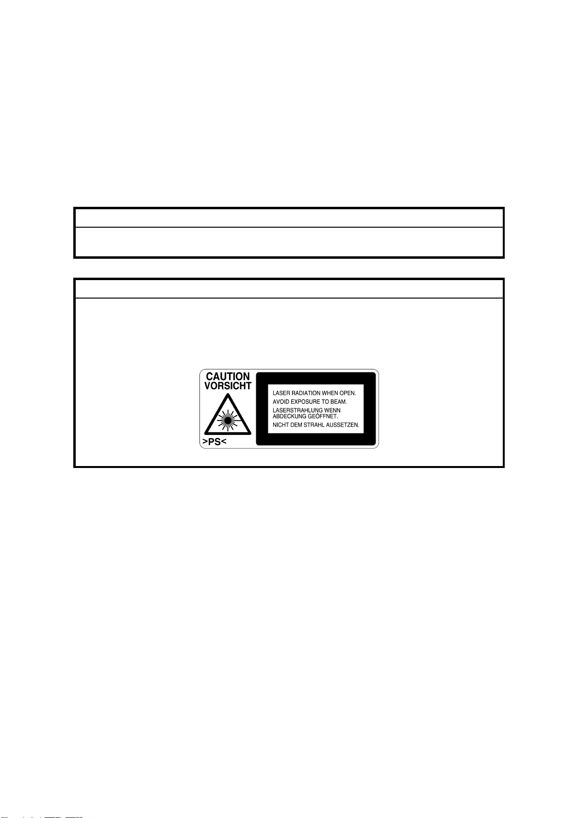
CAUTION MARKING:
Trademarks
Microsoft
®
, Windows®, and MS-DOS® are registered trademarks of Microsoft
Corporation in the United States and /or other countries.
PostScript
®
PCL
Ethernet
PowerPC
®
is a registered trademark of Adobe Systems, Incorporated.
is a registered trademark of Hewlett-Packard Company.
®
is a registered trademark of Xerox Corporation.
®
is a registered trademark of International Business Machines
Corporation.
Other product names used herein are for identification purposes only and may be
trademarks of their respective companies. We disclaim any and all rights involved
with those marks.
Page 25
Conventions in this Manual
This manual uses several symbols.
Symbol What it means
!
Refer to section number
See Core Tech Manual for details
Screw
Connector
Clip ring
E-ring
Lengthwise, SEF (Short Edge Feed)
Sideways, LEF (Long Edge Feed)
Page 26

Page 27
INSTALLATION
TAB
POSITION 1
PREVENTIVE MAINTENANCE
TAB
POSITION 2
REPLACEMENT AND ADJUSTMENT
TAB
POSITION 3
TROUBLESHOOTING
500-SHEET FINISHER G314
FOUR-BIN MAILBOX G312
TAB
POSITION 4
SERVICE TABLES
INTERCHANGE UNIT G305
DUPLEX UNIT G303
DETAILED DESCRIPTIONS
SPECIFICATIONS
PAPER TRAY UNIT G313
TAB
POSITION 5
TAB
POSITION 6
TAB
POSITION 7
TAB
POSITION 8
Page 28

Page 29

INSTALLATION
Page 30

Page 31

INSTALLATION REQUIREMENTS
1. INSTALLATION
1.1 INSTALLATION REQUIREMENTS
1.1.1 ENVIRONMENT
1. Temperature Range:
2. Humidity Range: 20% to 80% RH
3. Ambient Illumination: Less than 2,000 lux (keep the machine out of direct
4. Ventilation: 3 times/hr/person or more
5. Avoid exposing the machine to sudden temperature changes, which include:
1) Direct cool air from an air conditioner
2) Direct heat from a heater
6. Avoid installing the machine in areas that may be exposed to corrosive gas.
7. Install the machine at a location lower than 2,500 m (8,200 ft.) above sea level.
8. Install the machine on a strong, level base. (! 1.1.2)
9. Avoid installing the machine in areas that may be subjected to strong vibration.
10°C to 32°C (50°F to 89°F)
sunlight.)
Installation
1.1.2 MACHINE LEVEL
Front to back: Within 5 mm (0.2") of level
Right to left: Within 5 mm (0.2") of level
SM 1-1 G071
Page 32

INSTALLATION REQUIREMENTS
1.1.3 SPACE REQUIREMENTS
B
A: Over 100 mm (4")
B: Over 100 mm (4")
A
C
C: Over 550 mm (22")
D: Over 750 mm (30")
D
G070I001.WMF
1.1.4 POWER REQUIREMENTS
CAUTION
1. Insert the plug firmly in the outlet.
2. Avoid using an outlet extension plug or cord.
3. Ground the machine.
1. Input voltage level:
120 V, 60 Hz, More than 11 A
220 to 240 V, 50/60 Hz, More than 7 A
2. Permissible voltage fluctuation: ±10%
3. Do not put or place anything on the power cord.
G071 1-2 SM
Page 33

MACHINE INSTALLATION
1.2 MACHINE INSTALLATION
Refer to the Operating Instructions for details.
If the customer has a service contract, change the settings of the following SP
modes depending on the contract type.
Item SP No. Function Default
Meter charge
Counting method
A3/11" x 17"
double counting
PM warning
display 1
PM warning
display 2
SP5-930-1
(Meter_
Charge)
SP5-045-1
(Counter
Method)
SP5-104-1
(Double
Count)
SP5-931-1
(PM_Display
– Charger)
SP5-931-2
(PM_Display
– PCU)
Specifies whether the meter charge
mode is enabled or disabled.
If the user is doing the user PM
procedures, set meter charge to ‘Off’.
If the technician is doing all the PM,
set meter charge to ‘On’.
Meter charge mode enabled:
• The Counter menu appears
immediately after the Menu key is
pressed.
• The counter type selected by the
counting method (SP5-045-1,
Counter Method) can be displayed
with the Counter menu.
• The counter values can also be
printed with the Counter menu.
• The selected counter starts from a
negative number.
Meter charge mode disabled:
• The Counter menu is not
displayed.
• The total counter starts from 0.
Specifies whether the counting
method used in meter charge mode is
based on developments or prints.
Important:
This SP can only be done before the
negative counters are reset with SP7825-001 (Counter Reset)
Specifies whether the counter is
doubled for A3/11" x 17" paper.
Specifies whether the PM warning for
the charge corona unit is displayed
when the replacement time arrives.
1: Displayed
0: Not displayed
Specifies whether the PM warning for
the PCU is displayed.
1: Displayed
0: Not displayed
Off
Developments
No: Single
counting
1
1
Installation
SM 1-3 G071
Page 34

OPTIONS
Item SP No. Function Default
PM warning
display 3
Fax No. setting
Counter reset
SP5-931-3
(PM_Display
- Bank_
Feed)
SP5-812-2
(FAX TEL
No.)
SP7-825-1
(Counter
Reset)
Specifies whether the PM warning for
the feed rollers in the optional paper
feed unit is displayed.
1: Displayed
0: Not displayed
Programs the service station fax
number.
The number is printed on the counter
list when the meter charge mode is
selected, so that the user can fax the
counter data to the service station.
Resets the counters to 0.
Important: This must be done at
installation after all the above settings
have been finished. The negative
counters used in meter charge mode
will be reset to zero.
0
NOTE:
1) The default setting for this machine is meter-charge mode off.
2) The meter-charge counter cannot be reset.
1.3 OPTIONS
Refer to the Option Setup Guide for details.
No. Optional Unit Alternative Requirements
500-sheet finisher
1
2 4-bin mailbox No. 1
3 Interchange unit
Duplex unit
4
5 Paper tray unit
6 Printer hard disk
DIMM memory (64, 128, or 256
7
MB modules available)
IEEE1394 interface unit
8
9 User account enhancement unit
10 IEEE802.11b (Wireless LAN)
No. 2
• No. 3
• Hard disk or memory (extra 64
MB or more) for sort mode
• No. 3
• No. 3
• Extra 64 MB (or more) optional
SDRAM module
NOTE:
1) You cannot install the finisher and mailbox on the same machine.
2) You can install either 1 or 2 paper tray units.
G071 1-4 SM
Page 35

REMARKS FOR INSTALLATION
1.4 REMARKS FOR INSTALLATION
In case you install this printer or you instruct customers to install, please note the
following remark for development unit installation and replacement:
After installation or replacement of the development unit, print out the development
unit check sheet by user mode (User Mode – Maintenance – Development Unit
Check).
NOTE: For details please refer to the Quick Installation Guide.
Installation
SM 1-5 G071
Page 36

Page 37

PREVENTIVE MAINTENANCE
Page 38

Page 39

OVERVIEW
2. PREVENTIVE MAINTENANCE
2.1 OVERVIEW
Users Do the User PM Procedures
The user does PM for the items in section 2.2. The technician does PM for the
items in section 2.3. Meter-charge mode must be set to “off” (SP5-930
[Meter_Charge], ! 5.2).
All PM Done by Technicians
The technician does PM for the items in sections 2.2 and 2.3. Meter-charge mode
must be set to “on” (SP5-930, [Meter_Charge], ! 5.2).
Counters
When a maintenance counter for a unit has reached the limit, the corresponding
message is displayed on the operation panel. After completing the maintenance
procedure for that item, reset the counter (SP7-804, [PM_Clear ], ! 5.2).
2.2 USER MAINTENANCE
Abbreviations:
lean, Inspect, Lubricate, Replace, KiloPrints, KiloDevelopments, WheneverNecessary
C
Preventive
Maintenance
Main Unit
Item
T/B waste toner bottle
O/B waste toner bottle
Oil supply unit
Fusing unit with paper
feed roller
* : Replacement period calculated for a 50% color ratio (the actual waste toner bottle condition
is detected with the sensors)
** : Standard replacement period (the actual oil amount is detected with the sensor)
KD KP
50 120 30 120
R*
R*
R**
R
Detection Reset
Waste toner
sensors
Waste toner
sensors
Oil end
sensor/Oil
supply unit
counter
Exit sheet
counter
Auto-reset
(sensor)
Auto-reset
(sensor)
Manual reset
Manual reset
Machine
stops
Yes
Yes
Yes
Yes
SM 2-1 G071
Page 40

SERVICE MAINTENANCE
Item
Black development unit
Color development unit
PCU (includes charge
corona unit & dust
filters)
*Displayed with SP7-906 (PMCounter-PREV)
60 120 240
KD
R
R
R
Item WN Detection Reset
Registration roller
Dust shield glass
(LD unit)
Bottom plate pad
C None None No
C None None No
C None None No
Optional Paper Tray Unit
Item 150KP Detection Reset
Feed, pick-up, and
separation rollers
R None None No
Detection Reset
Dev. Bk
counter*
Dev. color
counter*
PCU counter*
Auto-reset
(memory chip)
Auto-reset
(memory chip)
Auto-reset (new
PCU sensor) No
Machine
stops
" damp cloth and
# dry cloth
Built-in cleaning
brush
" damp cloth and
# dry cloth
Machine
stops
" damp cloth and
# dry cloth
Machine
stops
Yes
Yes
Remarks
Remarks
2.3 SERVICE MAINTENANCE
Abbreviations:
lean, Inspect, Lubricate, Replace, KiloPrints, KiloDevelopments, WheneverNecessary
C
Main Unit
Bypass Tray
Item WN Remarks
Feed Roller
Pick-up Roller
Separation Roller
C
C
C
" damp cloth and
# dry cloth
" damp cloth and
# dry cloth
" damp cloth and
# dry cloth
G071 2-2 SM
Page 41

SERVICE MAINTENANCE
Optional Units
Paper Tray Unit
Item WN Remarks
Relay Roller
Bottom Plate Pad
C
C
" damp cloth and
# dry cloth
" damp cloth and
# dry cloth
Finisher
Item WN Remarks
Rollers
C
" damp cloth and
# dry cloth
Sensors C Blower blush or dry cloth
Anti-Static Brush C Blower blush or dry cloth
Bushings
Stapler
L
R
Launa oil when abnormal
noise occurs
Every 200K staples
(estimated replacement
period)
Mail Box
Item WN Remarks
Rollers
C
" damp cloth and
# dry cloth
Tray Paper Sensors C Blower blush or dry cloth
Duplex Unit
Item WN Remarks
Rollers
C
" damp cloth and
# dry cloth
Feed/exit sensors C Blower blush or dry cloth
Interchange Unit
Preventive
Maintenance
Item WN Remarks
Paper Exit Sensor C Blower blush or dry cloth
SM 2-3 G071
Page 42

Page 43

REPLACEMENT AND ADJUSTMENT
Page 44

Page 45

SPECIAL TOOLS
3. REPLACEMENT AND ADJUSTMENT
CAUTION
Turn off the main power switch and unplug the machine before beginning
any of the procedures in this section.
NOTE: This manual uses the following symbols.
! : See or Refer to : Screws : Connector : Clip ring
: E-ring
3.1 SPECIAL TOOLS
Part Number Part Name
N8036701 Flash Memory Card - 4MB
G0219350 Loop-back connector - Parallel
Adjustment
Replacement
SM 3-1 G071
Page 46

EXTERIOR COVERS
3.2 EXTERIOR COVERS
3.2.1 REAR COVER
1. Duct cover [A] (4 hooks)
2. Ozone filter [B]
3. Printer controller [C] ( x 2)
[A]
4. Rear cover [D] ( x 2)
[C]
G070R702.WMF
G070R703.WMF
[B]
Adjustment
Replacement
[D]
G071 3-2 SM
Page 47

EXTERIOR COVERS
3.2.2 LOWER LEFT COVER
1. Lower left cover [A] ( x 3)
[A]
3.2.3 UPPER COVER, OPERATION PANEL
1. Open the right cover [A].
2. Upper right cover [B]
3. Paper exit cover [C] ( x 1)
4. Open the front cover [D].
[F]
[E]
G070R704.WMF
Adjustment
Replacement
[C]
[B]
5. Upper cover [E] ( x 4)
6. Operation panel [F] (4 hooks,
x 2, x 1)
NOTE: Insert a screwdriver between
the upper cover and the main
unit and unhook the panel.
[D]
G070R701.WMF
[A]
SM 3-3 G071
Page 48

ELECTRICAL COMPONENTS
3.3 ELECTRICAL COMPONENTS
3.3.1 PRINTER CONTROLLER
! 3.2.1
NOTE: Remove the NVRAM from the old controller board, and install it on the new
one.
If the controller NVRAM is defective, reset the total counter to 0 after
changing the NVRAM, if meter charge mode is enabled.
3.3.2 CONTROLLER BOX
1. Rear cover (! 3.2.1)
2. Cooling fan [A] ( x 2)
NOTE: When reassembling,
install the fan with the
label facing the inside.
3. Controller box [B] ( x 11)
NOTE:
1) Do not remove the
BCU board base with
the controller box.
2) When putting back
the controller box,
take care not to
pinch the cable from
the I/O board.
3.3.3 BCU BOARD
[B]
[A]
G070R705.WMF
Adjustment
Replacement
1. Controller box (! 3.3.2)
[A]
2. All (12)
3. 1 flat cable
4. BCU board base [A] ( x 5)
5. BCU board [B] ( x 5)
NOTE: Remove the NVRAM from the old
BCU board, and install it on the
new one.
[B]
G071 3-4 SM
G070R706.WMF
Page 49

ELECTRICAL COMPONENTS
3.3.4 I/O BOARD
1. Controller box (! 3.3.2)
2. All (33)
3. I/O board [A] ( x 4)
3.3.5 PSU
1. Controller box (! 3.3.2)
2. Flywheel ( x 3) (! 3.4.1)
[A]
G070R707.WMF
[B]
Adjustment
Replacement
[C]
3. Duct [A] ( x 1, x 1)
NOTE: When removing and
reassembling the fan,
install it with the label
facing the outside.
4. PSU protector [B] ( x 1)
5. Unlink the main switch [C].
6. PSU base ( x 8, x 4)
NOTE:
1) Remove the PSU [D]
with the PSU base.
2) When reassembling,
check that the main
switch is linked to the
PSU.
[A]
[D]
G070R717.WMF
SM 3-5 G071
Page 50

ELECTRICAL COMPONENTS
3.3.6 HIGH VOLTAGE SUPPLY BOARD
1. Photoconductor unit (! 3.7)
2. Right inner cover (! 3.10.2)
3. Photoconductor unit rail [A] ( x 2)
4. [B] x 1
5. Bushing [C] x 1
[B]
[A]
G070R719.WMF
[C]
Adjustment
Replacement
6. High voltage supply board [D] ( x 17,
x 6)
[D]
G070R720.WMF
G071 3-6 SM
Page 51

DRIVE UNITS
3.4 DRIVE UNITS
3.4.1 DEVELOPMENT CLUTCHES
1. Controller box (! 3.3.2)
K/Y Development Units
1. Unhook the lock [A] and pull out
the clutch [B] ( x 1).
C/M Development Units
1. Flywheel [A] ( x 3)
2. Unhook the lock [B] and pull out
the clutch [C] ( x 1).
[A]
[B]
G070R708.WMF
Adjustment
Replacement
[C]
[A]
SM 3-7 G071
G070R709.WMF
[B]
Page 52

DRIVE UNITS
3.4.2 DEVELOPMENT MOTOR
1. Controller box (! 3.3.2)
2. Development motor [A] ( x 1,
x 3)
[A]
3.4.3 MAIN MOTOR
1. Controller box (! 3.3.2)
2. Flywheel [A] ( x 3)
3. Main motor [B] ( x 1, x 3)
G070R710.WMF
Adjustment
Replacement
[B]
[A]
G070R711.WMF
G071 3-8 SM
Page 53

DRIVE UNITS
3.4.4 PCU GEAR BOX AND OPC BELT CLEANING CLUTCH
1. I/O board (!3.3.4 )
2. Main motor (! 3.4.3)
3. C/M development unit clutch
(! 3.4.1)
4. Bracket [A] ( x 2)
5. Tension spring [B]
6. x 1 [C]
7. Gear box and clutch assembly
[D] ( x 5)
[A]
3.4.5 FUSING UNIT MOTOR
[C]
[B]
G070R712.WMF
[D]
Adjustment
Replacement
1. Rear cover (! 3.2.1)
2. Fusing unit motor ( x 1, x 3)
[A]
G070R713.WMF
[A]
SM 3-9 G071
Page 54

DRIVE UNITS
3.4.6 PAPER FEED MOTOR
1. Rear cover (! 3.2.1)
2. Pull out the handle [A].
3. Paper feed motor [B] ( x 1,
x 3)
[A]
3.4.7 PAPER FEED CLUTCH
1. Rear cover (! 3.2.1)
2. Pull out the handle [A].
3. Connector bracket [B] ( x 6,
x 2)
[A]
4. Paper feed clutch [C] ( x 1,
x 2)
3.4.8 REGISTRATION CLUTCH
[B]
G070R714.WMF
G070R716.WMF
[B]
[C]
Adjustment
Replacement
1. Rear cover (! 3.2.1)
2. Unhook the lock [A] and pull the
clutch out [B] ( x 1).
[B]
[A]
G070R715.WMF
G071 3-10 SM
Page 55

LASER OPTICS SECTION
3.5 LASER OPTICS SECTION
WARNING
Turn off the main switch and unplug the machine before beginning any of
the procedures in this section. Laser beams can cause serious eye injury.
3.5.1 CAUTION DECAL LOCATION
LD_CAUTION.TIF
G070R208.WMF
DANGER
Turn off the main switch and disconnect the power plug from the power
outlet before beginning any disassembly or adjustment of the laser unit.
This printer uses a class-1 laser beam with a wavelength of 650 nm and an
output of 7 mW. The laser can cause serious eye injury.
Adjustment
Replacement
SM 3-11 G071
Page 56

LASER OPTICS SECTION
3.5.2 LASER OPTICS HOUSING UNIT
1. Open the left cover [A].
2. ID chip connectors [B] ( x 4)
3. Development units [C] x 4
4. Rear cover (
! 3.2.1)
5. Left cover [D]
6. Lower left cover [E] ( x 3)
[B]
[E]
[C]
[A]
G070R301.WMF
Adjustment
Replacement
7. Controller box (
! 3.3.2)
8. Flat cable [F]
NOTE: When reassembling,
connect the flat cable with
the blue side up.
9. x 4 [G]
10. Harness clamps [H]
[G]
[D]
G070R201.WMF
[F]
[H]
G070R202.WMF
3-12 SM
G071
Page 57

LASER OPTICS SECTION
11. Open the front cover.
12. Remove the dust shield glass
cleaner lever [A] from the dust
shield glass cleaner.
NOTE: The dust shield glass
cleaner lever is the blue
lever at the right side of the
main switch.
13. LD cover [B] ( x 2)
14. Laser optics housing unit [C]
( x 4)
[A]
[B]
G070R209.WMF
Adjustment
Replacement
[C]
G070R203.WMF
SM 3-13 G071
Page 58

LASER OPTICS SECTION
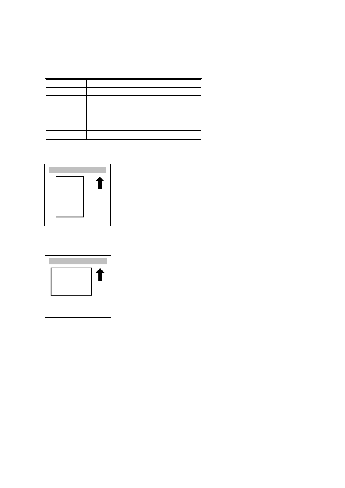
Adjusting for Image Skew
1. Positioning pin [A] ( x 1)
2. Loosen (x 4) [B].
3. Adjust the position of the laser
optics housing unit [! NOTE].
4. Fasten (x 4) [B].
NOTE: After changing the position
of the laser optics housing
unit, do not reinstall the
positioning pin. Keep the
pin in a safe place.
NOTE: When the image skews as
shown, move the unit 1 mm
in the direction of the black
arrow as shown in the upper
diagram.
1mm
[B]
[A]
G070R207.WMF
[! NOTE]
Adjustment
Replacement
Paper feed
(A3 SEF)
G070R001.WMF
G071 3-14 SM
Page 59

LASER OPTICS SECTION
Laser Beam Pitch Adjustment
1. Select test pattern 15 with
SP5-955-1 (Test Pattern –
Pattern).
2. Check if vertical black stripes
can be seen.
a) If stripes cannot be seen
(Figure 2), laser beam
pitch adjustment is not
required.
b) If stripes can be seen
(Figure 1), laser beam
pitch adjustment is
required. Go on to the
next step.
3. To adjust the laser beam pitch,
tighten or loosen the screw [A]
on the LD unit holder.
Feed direction
Figure 1 Figure 2
G070R952.WMF
[A]
Adjustment
Replacement
4. Set SP 2-917 (Test Pattern) to
‘On’. Then send a one-page
job to the printer, or print an
SMC list (SP 5-990-6, SP Print
mode – Non default).
5. Repeat steps 2 through 4 until
the black stripes disappear
(Figure 2).
G070R820.WMF
SM 3-15 G071
Page 60

LASER OPTICS SECTION
3.5.3 POLYGONAL MIRROR MOTOR AND LSD
WARNING
Do not touch any edges of the polygon mirror, spring, or bracket. These
edges can cause serious injury.
1. Development units, LD cover (! 3.5.2)
2. Cover [A] ( x 1)
NOTE: Before removing the cover, clean
the cover to prevent toner from
entering into the unit.
3. Polygonal mirror motor [B]
( x 1, x 4)
NOTE: Do not touch the surface.
of the polygonal motor.
4. Synch. detection board (LSD) [C]
( x 1, x 1)
[C]
[B]
[A]
G070R204.WMF
Adjustment
Replacement
G070R205.WMF
G071 3-16 SM
Page 61

DEVELOPMENT UNIT
3.6 DEVELOPMENT UNIT
CAUTION
Do not touch the development unit sleeves or ID chip terminals.
1. Open the left cover [A].
2. ID chip connector [B]
3. Lift up the development unit [C]
slightly, and pull it out of the
machine.
NOTE: Remove the units in the
order K, Y, C, M. For
example, before removing
the M unit, remove the K, Y,
and C units first.
[B]
[C]
[A]
G070R301.WMF
Adjustment
Replacement
4. Peel off the toner cartridge seal [D].
5. Reinstall the toner cartridge in the
development unit.
6. Keep the development unit level and
shake the development unit about 10
times from side to side.
NOTE:
1) Do not touch the
development roller or the
development roller gear.
2) Use caution not to drop the
cartridge or to damage it.
3) If the cartridge has not been
shaken well, the machine
takes a longer time to
initialize the development
unit, or an error message or
SC350 is displayed. When
either of them is displayed,
turn the main switch off and
on.
[D]
G070R901.WMF
G070R902.WMF
SM 3-17 G071
Page 62

DEVELOPMENT UNIT
7. Install the development unit in the
machine.
8. After installing the development
unit, print out the "development unit
check" sheet to confirm the correct
installation of the development unit
(Menu — Maintenance —
Devp.UnitCheck).
NOTE: A white line or band may
appear on one end of the
paper if a development is
incorrectly installed. To
correct this, pull out the
development unit partially
(about 30 mm) [E] and
slowly reinstall it.
[E]
G070R457.WMF
Adjustment
Replacement
G071 3-18 SM
Page 63

PHOTOCONDUCTOR UNIT (PCU)
3.7 PHOTOCONDUCTOR UNIT (PCU)
3.7.1 MAIN UNIT
NOTE:
1) Before replacing any of the parts or consumables in this section, cover
the floor with cloth or some sheets of paper.
2) Never tilt the unit. The toner may come out of the unit.
3) When handling the unit, grasp the brown (front) and green (top) grips.
Never touch the OPC (left) or transfer (right) belts.
4) After removing the photoconductor unit, cover it with a light-proof sheet.
Keep it in a dark place.
[C]
Adjustment
Replacement
1. Open the front cover [A].
2. Open the right cover [B].
3. x 4
4. Pull the OPC unit [C] out of the machine.
5. Grasp the brown and green grips.
6. Lift the unit and remove it.
[B]
[A]
G070R308.WMF
SM 3-19 G071
Page 64

PHOTOCONDUCTOR UNIT (PCU)
3.7.2 WASTE TONER BOTTLES
1. O/B waste toner bottle [A]
2. T/B waste toner bottle [B]
[A]
[B]
G070R302.WMF
G070R303.WMF
Adjustment
Replacement
G071 3-20 SM
Page 65

PHOTOCONDUCTOR UNIT (PCU)
3.7.3 CHARGE CORONA WIRE
1. Modular cable [A]
2. Loosen (x 1) [B]
3. Charge corona unit [C]
4. Front bracket ( x 1) [D]
5. Grid [E]
6. Rear bracket [F]
[B]
[D]
[A]
[E]
[C]
G070R304.WMF
Adjustment
Replacement
[F]
[H]
G070R305.WMF
7. Front wire cover [G]
8. Rear wire cover [H]
9. Wire cleaner [I]
[G]
[J]
10. Unhook the corona wire [J].
G070R259.WMF
SM 3-21 G071
[I]
Page 66

PHOTOCONDUCTOR UNIT (PCU)
3.7.4 CHARGE CORONA WIRE CLEANER MOTOR
1. Charge corona unit (! 3.7.3)
2. Front motor cover [A] ( x 3)
3. Motor [B]
[A]
3.7.5 OPC BELT CLEANING UNIT
1. Photoconductor unit (! 3.7.1)
2. Charge corona unit (! 3.7.3)
3. Drive gear [A] ( x 1)
4. Rear brace [B] ( x 1)
5. Front brace [C] ( x 1)
6. OPC belt cleaning unit [D]
( x 2)
NOTE: Hold up the
photoconductor unit
while removing the OPC
belt cleaning unit.
[A]
[B]
[B]
G070R306.WMF
[C]
G070R315.WMF
Adjustment
Replacement
3.7.6 IMAGE TRANSFER BELT CLEANING UNIT
1. Photoconductor unit (! 3.7.1)
2. Bracket [A] ( x 2)
3. Image transfer belt cleaning unit
[B]
G071 3-22 SM
[B]
G070R309.WMF
[A]
Page 67

PAPER TRANSFER UNIT
Rev. 03/2003
3.8 PAPER TRANSFER UNIT
3.8.1 VERTICAL TRANSPORT UNIT
1. Open the right lower cover [A].
2. Right cover [B] ( x 1)
[B]
3.8.2 TRANSFER ROLLER
⇒
1. Brace [A] ( x 1)
2. Guide [B]
NOTE: To remove the screws,
turn the roller unit on its
pivot.
3. Transfer roller [C]
( x 2, Bushing x 2, Bearing x 2)
[A]
[C]
G070R451.WMF
[B]
Adjustment
Replacement
[A]
SM 3-23 G071
G070R453.WMF
Page 68

PAPER TRANSFER UNIT
Cleaning the Paper Dust Mylar
–Quick Method–
1. Cover [A]
2. Sweep away paper dust with a
blower brush [B].
–When the paper dust has to be removed completely–
[D]
1. Bracket [C] ( x 2)
[E]
[C]
[B]
[A]
G070R562.WMF
Adjustment
Replacement
2. Plate spring [D]
3. Metal roller [E]
[G]
4. Bearing [F][G]
5. Spring [H][I]
6. Clean the mylar [J] with a dry cloth.
[I]
[F]
[H]
[J]
G070R561.WMF
G071 3-24 SM
Page 69

FUSING/PAPER EXIT
3.9 FUSING/PAPER EXIT
CAUTION
Turn off the main switch and wait until the fusing unit cools down before
beginning any of the procedures in this section. The fusing unit can cause
serious burns.
3.9.1 FUSING UNIT
[C]
1. Loosen the knob screw [A].
2. Pull the unit out of the machine.
3. Unhook the bottom stopper [B].
4. Grasp the rear end (marked with a
green label) [C].
5. Release the unit [D] from the base
plate [E].
[A]
[D]
Adjustment
Replacement
3.9.2 OIL SUPPLY UNIT
NOTE: When removing either of the
lamps (! 3.9.3), remove the
knob screw (! 3.9.1) before
removing the oil supply unit.
1. Fusing unit (! 3.9.1)
2. Put the fusing unit on a level place.
3. Oil supply unit [A]
NOTE:
1) Do not touch the oiling felt.
2) When reassembling, push the top of the oil supply unit so that the front
and rear hinges are correctly set.
[B]
[A]
[E]
G070R501.WMF
G070R502.WMF
SM 3-25 G071
Page 70

FUSING/PAPER EXIT
3.9.3 LAMPS
1. Oil supply unit (! 0)
2. Gear bracket [A] ( x 2)
3. Upper cover [B] ( x 2, shoulder
screw x 1)
4. Terminals [C], [D] ( x 5)
NOTE:
[C]: Pressure roller lamp
terminals
[D]: Heating roller lamp
terminals
[D]
[B]
[C]
G070R503.WMF
[A]
[D]
Adjustment
Replacement
5. Pull out the lamp (350 W) [E].
6. Pull out the lamp (770 W) [F].
NOTE: “350 W” and “770 W” are etched
on the respective terminals.
[H]
[F]
350W
G070R504.WMF
[E]
770W
G070R510.WMF
G071 3-26 SM
Page 71

FUSING/PAPER EXIT
3.9.4 FUSING INNER UNIT
1. Lamps (! 3.9.3)
2. Drive gear [A]
3. Knob screw [B] ( x 1)
4. Heating roller lamp harness terminal
[C] ( x 1)
5. Fusing inner unit [D] ( x 2,
x 3)
[B]
3.9.5 PRESSURE ROLLER THERMOFUSE
1. Fusing inner unit (! 3.9.4)
2. Pressure roller thermofuse [A] ( x 2)
[D]
[A]
G070R506.WMF
[C]
[A]
Adjustment
Replacement
G070R508.WMF
3.9.6 FUSING BELT UNIT AND PRESSURE ROLLER UNIT
1. Fusing inner unit (! 3.9.4)
2. Springs [A] [B]
3. Separate the fusing belt unit [C] and
pressure roller unit [D].
[A]
[C]
[D]
G070R507.WMF
[B]
SM 3-27 G071
Page 72

FUSING/PAPER EXIT
3.9.7 PRESSURE ROLLER THERMISTOR
1. Pressure roller unit (! 3.9.6)
2. Pressure roller lower stay [A]
( x 2)
3. Pressure roller thermistor
holder [B] ( x 1)
4. Pressure roller thermistor [C]
[C]
[B]
3.9.8 HOT ROLLER STRIPPERS
1. Oil supply unit (! 3.9.2)
2. Fusing lamps (! 3.9.3)
3. Fusing inner unit (! 3.9.4)
4. Gear [A]
NOTE: Remove the gear before
removing the stripper pawl
assembly; otherwise, the
gear may be damaged.
5. Hot roller stripper pawl assembly [B]
(Spring x 1, x 2)
[F]
[D]
[E]
G070R509.WMF
[C] [B]
[A]
[A]
Adjustment
Replacement
6. Hot roller stripper pawl [C]
G070R552.WMF
Reassembling
1. Put the spring [D] on the pawl.
2. Put the left end of the pawl in the square opening [E].
3. Put the front and rear ends of the pawl in the holder [F].
4. Confirm that the pawl moves correctly.
G071 3-28 SM
Page 73

FUSING/PAPER EXIT
3.9.9 PRESSURE ROLLER
[B]
[C]
[D]
1. Pressure roller unit (! 3.9.6)
2. Gear [A]
[E]
G070R900.WMF
[A]
Adjustment
Replacement
3. Hot roller stripper assembly [B] ( x 2)
4. Front bracket [C] ( x 1)
5. Bearing [D]
6. Pressure roller [E]
SM 3-29 G071
Page 74

FUSING/PAPER EXIT
3.9.10 OIL ABSORBERS
[A]
[C]
G070R516.WMF
[G]
[L]
[K]
[J]
[I]
1. Fusing inner unit (! 3.9.4)
2. Absorber 1 [A]
3. Pressure roller unit (! 3.9.6)
4. Absorber holder [B] ( x 1)
[H]
[F]
[D]
[B]
Adjustment
Replacement
[E]
G070R825.WMF
5. Absorber 2 [C]
6. Spring [D]
7. Absorber holder [E] ( x 1)
8. Absorber 3 [F]
9. Spring [G]
10. Base bracket [H] ( x 2)
11. Absorber holder [I] ( x 1)
12. Absorber 4 [J]
13. Absorber 5 [K]
14. Absorber 6 [L]
G071 3-30 SM
Page 75

FUSING/PAPER EXIT
3.9.11 PAPER EXIT UNIT AND PAPER EXIT/OVERFLOW SENSOR
CAUTION
Turn off the main switch and wait until the paper exit unit cools down
before beginning any of the procedures in this section. The paper exit unit
can cause serious burns.
1. Paper exit cover (! 3.2.3)
2. Paper exit unit [A] ( x 3,
x 1)
NOTE: Remove 2 connectors
before removing the unit.
To remove the last
connector, remove the
unit and turn it. The
connector is on the
bottom side.
3. Paper exit sensor [B]
4. Paper overflow sensor [C]
[C]
[B]
[A]
G070R601.WMF
Adjustment
Replacement
SM 3-31 G071
Page 76

PAPER FEED AND TRANSPORT
3.10 PAPER FEED AND TRANSPORT
3.10.1 FEED ROLLER AND FRICTION PAD
1. Paper tray [A]
[A]
2. x 1 [B]
3. Slide the shaft [C].
4. Feed roller [D] (1 hook)
5. Friction pad [E]
[B]
[D]
[E]
G070R101.WMF
Adjustment
Replacement
[C]
G070R102.WMF
G071 3-32 SM
Page 77

PAPER FEED AND TRANSPORT
3.10.2 REGISTRATION SENSOR
1. Front cover [A] (L-shaped-pin x 2)
2. Rear cover (! 3.2.1)
3. Upper cover (! 3.2.3)
4. Lower left cover (! 3.5.2)
5. Dust shield glass cleaning lever [B]
(! 3.5.2)
6. Charge corona unit (! 3.7.3)
7. Right cover (! 3.8.1)
8. Left inner cover door [C]
9. Left inner cover [D] ( x 2)
10. Right inner cover [E] ( x 3)
[C]
[B]
[D]
[A]
[E]
G070R103.WMF
G070R653.WMF
Adjustment
Replacement
SM 3-33 G071
Page 78

PAPER FEED AND TRANSPORT
11. Terminal [A] ( x 1)
NOTE: You have to remove the
terminal to lift the
transport stay (! step
14).
12. Transport guide [B] ( x 1)
[B]
G070R104.WMF
[A]
13. Drive gear [C] (1 hook)
14. Lift the transport stay [D] ( x 2)
and release the wire [E].
NOTE: You can see the wire clip
from the rear of the
machine.
15. Registration sensor [F] ( x 1,
x 1)
[E]
[D]
[F]
G070R105.WMF
Adjustment
Replacement
[C]
G071 3-34 SM
Page 79

PAPER FEED AND TRANSPORT
3.10.3 PAPER FEED SENSOR
1. Lift the transport stay [A]
(! 3.10.2)
2. Paper feed sensor [B] ( x 1)
NOTE: Unhook the rear two pawls
first, move the feeler, and
unhook the front pawl.
3.10.4 PAPER NEAR-END SENSOR
1. Lift the transport stay [A] (! 3.10.2)
2. Feeler [B]
3. Sensor bracket [C] ( x 1)
4. Paper near-end sensor [D] ( x 1)
3.10.5 PAPER END SENSOR
[A]
[B]
[A]
[C]
G070R106.WMF
[D]
G070R107.WMF
[B]
Adjustment
Replacement
1. Lift the transport stay [A] (! 3.10.2)
2. Feeler [B]
3. Sensor bracket [C] ( x 2)
4. Paper end sensor [D] ( x 1)
[A]
[D]
[C]
SM 3-35 G071
[B]
G070R108.WMF
Page 80

BYPASS TRAY
3.11 BYPASS TRAY
3.11.1 PICKUP/FEED ROLLER
1. Bypass tray ( x 3)
2. Upper cover [A] ( x 3)
[A]
3. Lift the paper end sensor feeler
[B].
4. Pick-up roller [C] (1 hook)
5. Paper feed roller [D] ( x 1)
[D]
[B]
G070R151.WMF
[C]
G070R152.WMF
Adjustment
Replacement
G071 3-36 SM
Page 81

BYPASS TRAY
3.11.2 PAPER FEED CLUTCH
1. Upper cover (! 3.11.1)
2. Rear cover [A] ( x 1)
3. Gear holder [B] ( x 3)
4. Gears [C][D]
5. Clutch [E] ( x 1)
[A]
[C]
G070R153.WMF
[E]
[D]
[B]
Adjustment
Replacement
3.11.3 REVERSE ROLLER
1. Bypass tray (! 3.11.1)
2. Turn the unit upside down.
3. Bottom cover [A] ( x 3)
4. Reverse roller [B] ( x 1)
Bottom of unit
Top of unit
[A]
G070R154.WMF
[B]
G070R155.WMF
SM 3-37 G071
Page 82

Page 83

TROUBLESHOOTING
Page 84

Page 85

SERVICE CALL
4. TROUBLESHOOTING
4.1 SERVICE CALL
4.1.1 SERVICE CALL CONDITIONS
Level Definition Reset Procedure
A
B
C
D
NOTE:
Fusing unit SCs displayed on the operation
panel. The machine is disabled. The user
cannot reset the SC.
SCs that disable only the features that use the
defective item. Although these SCs are not
shown to the user under normal conditions,
they are displayed on the operation panel only
when the defective feature is selected.
SCs that are not shown on the operation panel.
They are internally logged.
Turning the operation switch or main power
switch off then on resets the SC. The SC is
displayed on the operation panel. It is
redisplayed if it occurs after the main power
switch is turned on again.
1) All SCs are logged.
2) When an electrical circuit board has a problem, check the connections
before replacing the PCBs.
3) When a motor has a problem, check the mechanical load before
replacing the motor or sensor.
Turn the main switch off then on
before entering SP mode. Reset
the SC (set SP5-810
[SC_Reset] to 1), then turn the
main switch off then on again.
Turn the main power switch off
and on.
Logging only
Turn the main power switch off
and on.
Trouble-
shooting
SM 4-1 G071
Page 86

SERVICE CALL
4.1.2 SC TABLE
No.
Definition
Symptom Possible Cause
Polygon motor error 201 D
• The polygon motor starts operating. → The lock signal
is not detected within 20 seconds.
• The polygon motor starts operating. → The lock signal
is detected within 20 seconds. → After a 3-second
waiting time, no lock signal is detected within 20
seconds.
• The polygon motor strops operating. → The lock
signal is not detected within 20 seconds.
• The polygon motor is operating. → The lock signal
remains undetected for 0.5 seconds.
1st beam synchronization error 220 D
A polygon motor lock is detected; the LD door is closed;
the LD remains on. → The LD error (1st beam
synchronization error) continues for 0.5 seconds.
2nd beam synchronization error 221 D
A polygon motor lock is detected; the LD door is closed;
the LD remains on. → The LD error (2nd beam
synchronization error) continues for 0.5 seconds.
FGATE on error 230 D
A transfer belt mark is detected. → No FGATE on signal
is detected within 175+50 milliseconds.
FGATE off error 231 D
A FGATE assert signal is detected. → The FGATE
negate signal is not detected within 30 seconds.
LD error 241 D
An LD error continues for 0.5 seconds. (After an LD
error is detected, an LD error release is written to the
GAVD chip during monitoring.)
Image transfer belt mark detection error 280 D
• An imaging process starts. → No belt mark is
detected in 1 revolution.
• A color imaging process starts. → A mono color
image is transferred. → FGATE becomes active. →
No belt mark is detected in 1 revolution.
• Thick paper or OHP film is used. → The belt slows
down. → No belt mark is detected in 1 revolution.
GAPCI communication error 281 D
Data is transferred. → The CPU does not detect the
communication ACK signal from GAPCI.
GAVD communication error 282 D
Data is transferred. → The CPU does not detect the
communication ACK signal from GAVD.
• Defective polygon
motor
• Defective harness
• Disconnected
synchronization
detector board
• Defective LD unit
• Defective BCU
• Disconnected
synchronization
detector board
• Defective LD unit
• Defective BCU
• Defective BCU
• Defective BCU
• Defective LD unit
• Defective BCU
• Poor electrical
connection
• Noise
• Defective BCU
• Defective BCU
G071 4-2 SM
Page 87

SERVICE CALL
No.
Definition
Symptom Possible Cause
Charge corona unit electrical leak 300 D
The charge corona unit keeps outputting; the unit is
operating at the minimum PWM duty value. → 4.5 Volt
(or more) is returning for 60 milliseconds.
Charge corona unit disconnection 301 D
The charge corona unit keeps outputting. → The unit is
operating at the maximum PWM duty value for 60
milliseconds.
Charge grid electrical leak 302 D
The charge grid keeps outputting. → The returning
voltage exceeds the target by 0.5 Volt or more for 120
milliseconds.
Charge corona unit cleaner error 305 D
• Cleaning starts. → The lock signal is not detected
within 30 seconds.
• Cleaning starts. → The cleaner turns. → The lock
signal is detected within 6 seconds.
• The lock signal is detected while the unit is moving
away from the HP. → The next lock signal is detected
within 6 seconds after the unit has turned toward the
HP.
Development error 1 (K/Y) 350 D
A development process starts. → The returning voltage
exceeds the target by 0.5 Volt or more for 60
milliseconds.
Development error 2 (C/M) 351 D
A development process starts. → The returning voltage
exceeds the target by 0.5 Volt or more for 60
milliseconds.
Development motor error 352 D
• The development motor starts or changes speed. →
The motor does not detect a 1-second lock signal
within 3 seconds.
• The development motor starts. → The lock signal is
detected during normal operation. → The lock signal
is interrupted for 1 second or more.
• Short circuit in the
charge corona unit
• Defective high
voltage supply board
• Defective harness
(BCU - high voltage
supply board)
• Defective PCU
installation
• Defective high
voltage supply board
• Defective harness
(BCU - high voltage
supply board)
• Short circuit in the
charge grid
• Defective high
voltage supply board
• Defective harness
(BCU - high voltage
supply board)
• Defective cleaner
• Short circuit in the
development unit
• Defective high
voltage supply board
• Defective harness
(BCU - high voltage
supply board)
• Short circuit in the
development unit
• Defective high
voltage supply board
• Defective harness
(BCU - high voltage
supply board)
• Defective
development motor
Trouble-
shooting
SM 4-3 G071
Page 88

SERVICE CALL
No.
Definition
Symptom Possible Cause
1st transfer (image transfer) electric leakage (+) 400 D
Image transfer starts. → The process operates at the
minimum PWM duty value. The returned current
exceeds 1.8 V for 180 milliseconds.
1st transfer (image transfer) electric leakage (–) 401 D
Image transfer starts. → The negative (–) output is at the
maximum PWM duty value for 60 milliseconds.
2nd transfer (paper transfer) electric leakage (+) 410 D
Paper transfer starts. → The positive (+) output is at the
minimum PWM duty value. → The returning voltage
stays at 2.7 V or more for 60 milliseconds.
2nd transfer (paper transfer) electric leakage (–) 411 D
Paper transfer starts. → The negative (–) output is at the
minimum PWM duty value. → The returning voltage
stays at 4.5 V or more for 60 milliseconds.
2nd transfer (paper transfer) disconnection (+) 412 D
Paper transfer starts. → The positive (+) output is at the
maximum PWM duty value for 60 milliseconds.
2nd transfer (paper transfer) disconnection (–) 413 D
Paper transfer starts. → The negative (–) output is at the
maximum PWM duty value for 60 milliseconds.
• Short circuit in the
image transfer unit
• Defective image
transfer belt
• Defective high
voltage supply board
• Defective harness
(BCU - high voltage
supply board)
• Short circuit in the
image transfer belt
• Defective high
voltage supply board
• Defective harness
(BCU - high voltage
supply board)
• Short circuit in the
paper transfer unit
• Defective high
voltage supply board
• Defective harness
(BCU - high voltage
supply board)
• Short circuit in the
paper transfer unit
• Defective high
voltage supply board
• Defective harness
(BCU - high voltage
supply board)
• Right cover not
closed
• Defective transfer
roller contact
mechanism
• Defective high
voltage supply board
• Defective harness
(BCU - high voltage
supply board)
• Right cover not
closed
• Defective transfer
roller contact
mechanism
• Defective high
voltage supply board
• Defective harness
(BCU - high voltage
supply board)
G071 4-4 SM
Page 89

SERVICE CALL
No.
Definition
Symptom Possible Cause
Discharge error (fusing bias) 420 D
The discharge circuit is operating at the maximum PWM
duty value for 60 milliseconds.
Discharge plate error 421 D
During discharging, the leakage detection signal is low
for 60 milliseconds.
Transfer belt cleaning error 430 D
Cleaning is operating at the maximum PWM duty value
for 60 milliseconds.
Main motor error 440 D
• The main motor starts or changes speed. → The lock
signal does not continue for 1 second within 3
seconds.
• The main motor starts. → The lock signal is detected
and operation proceeds normally. → The lock signal
is interrupted for 1 second.
Temperature sensor error 460 D
The output is 4.5 V (or higher) or 0.3 V (or lower) for 12
seconds.
Humidity sensor error 461 D
The output is 4.5 V (or higher) or 0.3 V (or lower) for 12
seconds.
ID sensor error 480 D
The ID sensor is being calibrated (process control, step
1) → While the LED is off, the output voltage is 0.5 V or
lower.
Transfer belt mark detection error 481 D
The main motor is operating; and the lock signal is
detected. → The belt mark sensor signal does not
change for 120 milliseconds.
2nd tray error 502 B
• The tray lift motor turns on. → The top of the paper
stack is not detected for 13 seconds.
• The tray is set. → The top of the paper stack is
detected. → The bottom plate is lowered. → The
stack detection is not cleared within 5 seconds. →
These steps are repeated 4 times.
• Discharge pin short
circuit
• Defective high
voltage supply board
• Defective harness
(BCU - high voltage
supply board)
• Scratched fusing belt
• Short circuit in the
discharge plate
• Defective high
voltage supply board
• Defective harness
(BCU - high voltage
supply board)
• Short circuit in the
transfer belt cleaning
unit
• Defective high
voltage supply board
• Defective harness
(BCU - high voltage
supply board)
• Defective main motor
• Short circuit in the
temperature sensor
• Defective circuit
• Defective connector
• Short circuit in the
humidity sensor
• Defective circuit
• Defective connector
• Defective ID sensor
• Defective connector
• Defective main motor
• Image transfer belt
out of position
• Belt mark blurred or
absent
• Defective paper
height sensor
• Defective tray lift
motor
Trouble-
shooting
SM 4-5 G071
Page 90

SERVICE CALL
No.
Definition
Symptom Possible Cause
3rd tray error 503 B
• The tray lift motor turns on. → The top of the paper
stack is not detected for 13 seconds.
• The tray is set. → The top of the paper stack is
detected. → The bottom plate is lowered. → The
stack detection is not cleared within 5 seconds. →
These steps are repeated 4 times.
Duplex unit communication error 515 D
• A connection error occurs.
• The signal is sent from the printer to the duplex unit
every 3 seconds while paper is not transported by the
unit. However, the duplex unit does not respond within
5 seconds.
Paper feed motor error 520 D
• The motor starts or changes speed. → The lock signal
does not continue for 1 second within a 3-second
interval.
• The motor starts. → The lock signal is detected and
operation proceeds normally. → The lock signal is
interrupted for 1 second.
Thermistor disconnection (heating roller) 541 A
The fusing unit starts warm up to the print ready
temperature. → The temperature does not reach 7°C for
10 seconds.
Fusing warm-up timeout (heating roller) 542 A
The main switch is turned on or a cover is closed. →
The heating roller does not reach the warm-up
temperature within 50 seconds.
Overheat error (heating roller) 543 A
The heating roller thermistor detects 220°C for 5
seconds.
Low temperature error (heating roller) 544 A
During standby or operation, the heating roller
thermistor detects 100 °C or less for 5 seconds.
Full power error (heating roller) 545 A
Fusing unit warm-up is complete. → The heating roller
stops turning. → The heating roller lamp keeps
outputting the maximum power for 30 seconds.
• Defective paper
height sensor
• Defective tray lift
motor
• Defective duplex unit
board
• Defective BCU
• Defective IOB
• Defective connection
(Main unit - Duplex
unit)
• Defective paper feed
motor
• Defective thermistor
• Thermistor loose
connection
• Defective connector
• Defective lamp
(loose connection,
thermostat failure,
PSU, thermostat)
• Incorrect detection
(loose thermistor
connection, fusing drawer loose
connection)
• Short circuit
• Defective BCU board
• Defective PSU
• Defective lamp
(loose connection,
thermostat failure,
PSU, thermostat)
• Incorrect detection
(loose thermistor
connection, fusing drawer loose
connection)
• Thermistor loose
connection
• Fusing - drawer
loose connection
G071 4-6 SM
Page 91

SERVICE CALL
No.
Definition
Unstable temperature (heating roller) 546 A
• The heating roller thermistor detects unstable
temperature increases or decreases within 60
seconds.
Thermistor disconnection (pressure roller) 551 A
The pressure roller thermistor detects7°C or lower for 30
seconds.
Warm-up time over (pressure roller) 552 A
The main switch is turned on or a cover is closed. →
The fusing pressure roller does not reach the ready
temperature within 200 seconds.
Overheat error (pressure roller) 553 A
The pressure roller thermistor detects 220°C for 5
seconds.
Low temperature error (pressure roller) 554 A
During standby or operation, the pressure roller
thermistor detects 80°C or less for 5 seconds.
Full power error (pressure roller) 555 A
Fusing unit warm-up is complete.→ The fusing pressure
roller stops turning. → The pressure roller lamp keeps
outputting the maximum power for 200 seconds.
Unstable temperature (pressure roller) 556 A
• The pressure roller thermistor detects unstable
temperature increases or decreases within 60
seconds.
Zero cross error 560 D
The main switch is turned on; the fusing relay turns on.
→ 50 Hz or 60 Hz is not detected within 5 seconds.
670 D No response from BCU at power on
EEPROM error 680 D
The main switch is turned on.→ EEPROM is not
connected.
Symptom Possible Cause
• Thermistor loose
connection
• Fusing - drawer
loose connection
• Thermistor loose
connection
• Defective harness
• Defective connector
• Defective lamp
(loose connection,
thermostat failure,
PSU, thermostat)
• Incorrect detection
(thermistor loose
connection, fusing drawer loose
connection)
• Loose connection
• Defective BCU board
• Defective PSU
• Defective lamp
(loose connection,
thermostat failure,
PSU, thermostat)
• Incorrect detection
(thermistor loose
connection, fusing drawer loose
connection)
• Thermistor loose
connection
• Fusing - drawer
loose connection
• Thermistor loose
connection
• Fusing - drawer
loose connection
• Defective relay circuit
• Defective PSU
• Incorrect power
supply
• Loose connection
• Defective controller
• Defective BCU
• Incorrect EEPROM
connection
Trouble-
shooting
SM 4-7 G071
Page 92

SERVICE CALL
No.
Definition
Symptom Possible Cause
PER command error 687 D
• Some image data is transferred. → The controller
does not report the necessary memory address.
• The PES command is issued. → The controller does
not issue the necessary memory report (PER)
command within 6 seconds..
Four-bin mail box communication error 730 D
• A connection error occurs.
• The UART reports a communication error.
• In other cases than paper transport, after an every-3-
second command is sent, the mail box does not
respond within 5 seconds.
Finisher communication error 740 D
• A connection error occurs.
• The UART reports a communication error.
• In other cases than paper transport, after an every-3-
second command is sent, the finisher does not
respond within 5 seconds.
Finisher jogger motor error 741 D
The jogger home position sensor (on/off) is not detected
in a given time.
Finisher stapler unit error 742 D
• The stapler does not return to home position within 1
second.
Finisher output tray motor error 743 D
The stack height and lever sensors do not detect paper.
Finisher output tray motor lock 744 D
The tray is locked for 10 seconds.
Finisher paper detection error 745 D
The stack height and lever sensors do not correctly
detect paper.
1st paper tray unit communication error 750 D
• A connection error occurs.
• The UART reports a communication error.
• In other cases than paper transport, after an every-3-
second command is sent, the paper tray unit does not
respond within 5 seconds.
2nd paper tray unit communication error 751 D
• After the 1st paper tray has recognized the 2nd paper
tray, the trays cannot communicate with each other.
• After the 1st paper tray has recognized the 2nd paper
tray, an ATM (CPU reset) is sent from the 2nd paper
tray.
• Poor connection
between BCU and
controller
• Defective BCU
• Defective controller
• Defective mail box
control board
• Defective BCU
• Defective IOB
• Incorrect installation
• Defective finisher
control board
• Defective board
• Defective BCU
• Defective IOB
• Incorrect installation
• Defective jogger
motor
• Defective jogger
home position sensor
• Defective stapler unit
• Defective motor
• Defective paper tray
unit control board
• Defective BCU
• Defective IOB
• Defective connection
(Paper tray - main
unit)
• Defective paper tray
unit control board
• Defective connection
(1st - 2nd paper tray
G071 4-8 SM
Page 93

CONTROLLER ERROR TABLE
4.2 CONTROLLER ERROR TABLE
The table lists the controller error codes. If an error occurs, the code is displayed
when the main switch is turned on or after the startup self-diagnostics.
NOTE: For the startup self-diagnostics, see section 5.3.
Code Description Required Action
640 BCU – Controller
communication error
(no response)
641 BCU – Controller
communication error
(no response)
800 Video output error (K)
801 Video output error (Y)
802 Video output error (M)
803 Video output error (C)
818 Watchdog error Turn the main switch off and on.
819 Fatal error Turn the main switch off and on.
820 Self-diagnostics error:
CPU [XXXX]: Detailed
error code
821 Self-diagnostics error:
ASIC
822 Self-diagnostics error:
HDD (Hard Disk Drive)
[XXXX]: Detailed error
code
823 Self-diagnostics error: NIB
[XXXX]: Detailed error
code
824 Self-diagnostics error:
Standard NVRAM
827 Self-diagnostics error:
Standard SRAM DIMM
[XXXX]: Detailed error
code
Turn the main switch off and on.
Replace the controller.
Replace the BCU.
Turn the main switch off and on.
Check the connection between BCU and controller.
Replace the controller.
Replace the BCU.
Data transfer starts to the BCU, but the transfer
completion command does not return to the controller
within the required time.
Defective controller board
Replace the controller.
See NOTE at the end of this table
Check and/or replace the RAM DIMM.
Check and/or replace the ROM DIMM.
Replace the controller.
See NOTE at the end of this table
Turn the main switch off and on.
Reinstall the controller system firmware.
Replace the controller.
Turn the main switch off and on.
Reinstall the controller system firmware.
Replace the RAM DIMM.
Replace the controller board.
Turn the main switch off and on.
Check that the HDD is properly connected to the
controller.
Replace the HDD.
Replace the controller.
Turn the main switch off and on.
Replace the controller.
Turn the main switch off and on.
Check that the standard NVRAM is firmly inserted into the
socket.
Replace the NVRAM.
Replace the controller.
Turn the main switch off and on.
Replace the SRAM DIMM.
Replace the controller.
Trouble-
shooting
SM 4-9 G071
Page 94

CONTROLLER ERROR TABLE
Code Description Required Action
828 Self-diagnostics error :
ROM [XXXX]: Detailed
error code
829 Self-diagnostics error:
optional RAM [XXXX]:
Detailed error code
835 Self-diagnostics error:
Centronics interface
[XXXX]: Detailed error
code
836 Self-diagnostics error:
Font ROM (standard)
838 Self-diagnostics error:
Font ROM (clock
generator)
850 Network interface error Turn the main switch off and on.
851 IEEE1394 interface error Turn the main switch off and on.
853 IEEE802.11b error - card
not detected (power-on)
854 IEEE802.11b error - card
not detected (during
operation)
855 IEEE802.11b error Check the wireless LAN card connection.
856 IEEE802.11b interface
board error
857 USB interface error
detected.
860 HDD: Error detected at
power up (partition error,
unformatted disk,
incorrect disk type)
861 HDD: Reboot error Turn the main switch off and on.
862 Defective sector
management maximum
863 HDD: Read error Turn the main switch off and on.
864 HDD: CRC error Turn the main switch off and on.
865 HDD: Access error Turn the main switch off and on.
Turn the main switch on and off.
Replace the ROM DIMM
Replace the controller.
Turn the main switch off and on.
Replace the RAM DIMM.
Replace the controller board.
Turn the main switch off and on.
Check the connection between the Centronics connector
and loop-back connector.
Reconnect the loop-back connector.
Replace the controller.
Turn the main switch off and on.
Replace the standard ROM-DIMM.
Replace the controller.
Replace the controller.
Replace the IEEE1394 interface board.
Replace the controller.
Check the wireless LAN card connection.
Replace the wireless LAN card.
Check the wireless LAN card connection.
Replace the wireless LAN card.
Replace the wireless LAN card.
Check the wireless LAN interface board connection.
Replace the interface board.
Check the USB connections, make sure that they are
securely connected.
Replace the controller board.
Turn the main switch off and on.
Reformat the HDD (SP 5-832-1 [HDD Init]).
Replace the HDD.
Check the connection between HDD and controller.
Check and replace the cables.
Replace the HDD.
Replace the controller.
Replace the HDD.
Replace the HDD.
Replace the controller.
Replace the HDD.
Replace the HDD.
G071 4-10 SM
Page 95

CONTROLLER ERROR TABLE
Code Description Required Action
900 Electrical counter error Turn the main switch off and on.
Check the connection between NVRAM and controller.
Replace the NVRAM.
Replace the controller.
990 Software performance
error
991 Unexpected software
error
998 Application start error Turn the main switch off and on.
999 Program installation error Controller DIP SW1 setting incorrect.
Turn the main switch off and on.
Reinstall the controller and/or engine main firmware.
See NOTE at the end of this table.
The machine does not stop and the SC code is not
displayed. The machine automatically recovers. However,
the SC code is logged in the engine summary sheet
(SMC).
Check that the RAM DIMM and ROM DIMM are properly
connected.
Reinstall the controller system firmware.
Replace the controller.
Defective software on IC card.
Controller software download error.
Replace the controller.
NOTE: If a problem always occurs in a specific situation (for example, same printer
driver settings, same image file), the problem may be caused by a software
error. In this case, send the following data and information to your product
specialist.
Trouble-
shooting
• Symptom/Possible causes/Action taken
• Summary sheet (SP mode ‘1 Service’, [Print Summary])
• SMC All (SP5-990-2, SP print mode - All)
• Logged data (SP5-990-4, SP print mode - Logging)
• Printer driver settings used when the problem occurs
• All data displayed on the screen (SC code, error code, and program
address where the problem is logged.)
• Image file which causes the problem, if possible
SM 4-11 G071
Page 96

BLOWN FUSE CONDITIONS
is displayed. The interchange unit (and
4.3 BLOWN FUSE CONDITIONS
Fuse
Power Supply Board
FU1 (N.A.)/
CB1 (Eur./Asia)
FU2 6.3A/250V 3.15A/250V No response
FU3 4A/125V 4A/125V
FU4 4A/125V 4A/125V
*1: Vaa (+24V) for the optional tray is cut.
*2: Vaa (+24V) for the interchange unit is cut.
15A/125V 8A/250V No response
Rating
115V 220 ~ 240V
Symptom when turning on the main switch
“Tray 2 Hardware Problem ” is displayed. The
optional tray does not operate.*1
“Ready”
the finisher and/or the 4-bin mail box and/or
duplex) does not operate.*2
4.4 CHECK POINTS FOR IMAGE PROBLEMS AT
REGULAR INTERVALS
Symptoms for image problems at regular intervals depend on the circumference of
certain components. The following diagram shows the possible symptoms (black or
white dots at regular intervals) .
Paper feed
Pitched images
G070T801.WMF
Color spots at 2.1 inches (54-mm) intervals: Development roller in the development
unit
Abnormal image at 2.7 inches (68-mm) intervals: Transfer roller
Abnormal image at 7.4 inches (188-mm) intervals: Fusing belt in the fusing unit
Abnormal image at 5 inches (125-mm) intervals: Pressure roller in the fusing unit
G071 4-12 SM
Page 97

SERVICE TABLES
Page 98

Page 99

SERVI CE PROGRAM MODE
5. SERVICE TABLES
5.1 SERVICE PROGRAM MODE
CAUTION
Before starting a service program, check that no data is coming into the
printer. If data is coming in, wait until the data is completely processed.
5.1.1 OPERATION PANEL KEYS
[B]
[C]
[A]
[H]
On Line Menu
Job Reset
Form Feed
[G]
[A]: Online
[B]: Menu
[C]: Escape
[D]: Up arrow
Power
Error
Data In
[E]: Down arrow
[F]: Enter
[G]: Form feed
[H]: Reset
Escape
#
Enter
[F]
G070S001.WMF
[D]
[E]
Service
Tables
SM 5-1 G071
Page 100

SERVICE PROGRAM MODE
5.1.2 STARTING SERVICE PROGRAM MODE
You can enter service mode with either of the following procedures.
Procedure 1
1. Turn the main switch off.
2. Press the online key and the escape key at the same time, and hold them.
3. Turn the main switch on.
4. Wait until “SYSTEM ver V.x.xx. 1. Service” is displayed.
NOTE: “ver V.x.xx.” indicates the machine’s firmware version.
Procedure 2
1. Press the up arrow key and the down arrow key at the same time, and hold
them for about 5 seconds.
NOTE: At this moment, the display does not change.
2. Press the enter key. “SYSTEM ver V.x.xx. 1. Service” is displayed.
NOTE: “ver V.x.xx.” indicates the machine’s firmware version.
5.1.3 MAIN MENU
1. The main menu has three sub menus (see below). Press the up arrow key or
the down arrow key to scroll through these sub menus.
1) Service: Goes to the controller service modes
2) Engine: Goes to the engine service modes
3) End: Exits from the main menu
2. Press the enter key.
3. Press the up arrow key or the down arrow key to scroll through the items in the
selected sub menu.
4. To exit from the sub menu, press the escape key.
G071 5-2 SM
 Loading...