

Page 1

Setup Guide
Read This First
Trademarks.............................................................................................................3
Safety Information .................................................................................................4
Positions of RWARNING and RCAUTION labels ..............................................8
ENERGY STAR Program .....................................................................................10
How to Read This Manual ...................................................................................11
Guide to the Printer
Exterior: Front View.............................................................................................12
Exterior: Rear View ..............................................................................................14
Inside.....................................................................................................................15
Control Panel........................................................................................................16
Setting Up
Where to Put the Printer......................................................................................18
Checking the Contents of the Box .....................................................................21
Unpacking.............................................................................................................23
Installing the Toner Cartridge.............................................................................29
Loading Paper......................................................................................................33
Turning the Power On .........................................................................................35
Selecting the Display Language.........................................................................37
Test Printing .........................................................................................................39
G1058604A_1.10 GB GB G105-8600A Copyright © 2004, 2005 1
Page 2

Installing Options
Available Options.................................................................................................41
Option List ................................................................................................................41
Option Installation Flow Chart ..................................................................................42
Installing Options......................................................................................................43
Caution when re-installing the controller board........................................................44
Attaching Paper Feed Unit Type 4000................................................................46
Attaching Memory Unit Type D 128MB, Memory Unit Type E 256MB (SDRAM
Module) ...............................................................................................................49
Attaching User Account Enhance Unit Type E .................................................55
Attaching Hard Disk Drive Type 4000 ................................................................60
Formatting the Hard Disk Drive................................................................................65
Attaching IEEE 1394 Interface Board Type B....................................................67
Attaching IEEE 802.11b Interface Unit Type H .................................................. 70
Attaching Bluetooth Interface Unit Type 3245 ..................................................74
Attaching IEEE 1284 Interface Board Type A....................................................78
Attaching Network Data Protection Unit Type B...............................................80
Connecting the Printer
Network Connection ............................................................................................82
USB Connection...................................................................................................84
Parallel Connection .............................................................................................85
IEEE 1394 Connection .........................................................................................86
Configuration
Ethernet Configuration........................................................................................87
IEEE 802.11b (Wireless LAN) Configuration .....................................................92
IEEE 1394 Configuration .....................................................................................98
IP over 1394.............................................................................................................98
SCSI print...............................................................................................................100
Installing the Printer Driver
Quick Install........................................................................................................102
Install the Operating Instructions.....................................................................104
2
Page 3

Read This First
Trademarks
Microsoft, Windows and Windows NT are registered trademarks of Microsoft
Corporation in the United States and/or other countries.
IPS-PRINT Printer Language Emulation Copyright© 1999-2000 Oak Technology, Inc., All rights reserved.
Bluetooth
Other product names used herein are for identification purposes only and might
be trademarks of their respective companies. We disclaim any and all rights to
those marks.
The proper names of the Windows operating systems are as follows:
•Microsoft
•Microsoft
•Microsoft
• The product names of Windows
Microsoft
Microsoft
Microsoft
• The product names of Windows
Microsoft
Microsoft
• The product names of Windows Server
Microsoft
Microsoft
Microsoft
• The product names of Windows NT
Microsoft
Microsoft
®
is a registered trademark of the Bluetooth SIG, Inc. worldwide.
®
Windows® 95 operating system
®
Windows® 98 operating system
®
Windows® Millennium Edition (Windows Me)
®
®
Windows® 2000 Advanced Server
®
Windows® 2000 Server
®
Windows® 2000 Professional
®
Windows® XP Professional
®
Windows® XP Home Edition
®
Windows ServerTM 2003 Standard Edition
®
Windows ServerTM 2003 Enterprise Edition
®
Windows ServerTM 2003 Web Edition
®
Windows NT® Server 4.0
®
Windows NT® Workstation 4.0
2000 are as follows:
®
XP are as follows:
TM
2003 are as follows:
®
4.0 are as follows:
G1058604A_1.10 Copyright © 2004, 2005 3
Page 4

Read This First
Safety Information
When using your printer, the following safety precautions should always be followed.
In this manual, the following important symbols are used:
Indicates a potentially hazardous situation which, if instructions are not followed, could result in
death or serious injury.
Indicates a potentially hazardous situation which, if instructions are not followed, may result in
minor or moderate injury or damage to property.
4
Page 5

Read This First
• Confirm the wall outlet is near the machine and freely accessible, so
that in the event of emergency, it can be unplugged easily.
• Plug and unplug the power cable with dry hands, or an electric shock
could occur.
• Only connect the machine to the power source described in the manual.
• Avoid multi-wiring.
• Do not damage, break or make any modifications to the power cord.
Do not place heavy objects on it, pull it hard or bend it more than necessary. These actions could cause an electric shock or fire.
• Do not incinerate spilled toner or used toner. Toner dust is flammable
and might ignite when exposed to an open flame.
• Disposal should take place at an authorized dealer or an appropriate
collection site.
• If you dispose of the used toner containers yourself, dispose of them
according to local regulations.
• Do not take apart or attempt any modifications to this machine. There
is a risk of fire, electric shock, explosion or loss of sight. If the machine has laser systems, there is a risk of serious eye damage.
• Dispose at an authorized dealer or approved collection site. If you dispose of the used toner containers yourself, do so according to local
regulations.
• Do not risk electric shock by handling the power cord or plug with wet
hands.
• Do not take apart or attempt any modifications to this machine. There
is a risk of fire, electric shock, explosion or loss of sight. If the machine has laser systems, there is a risk of serious eye damage.
• Keep the machine away from flammable liquids, gases, and aerosols.
A fire or an electric shock might occur.
5
Page 6

Read This First
• Place no objects on the left or inner cover.
• Do not pull out the paper tray forcefully. If you do, the tray might fall and
cause an injury.
• The inside of this printer becomes very hot. Do not touch parts labelled “v”
(indicating a hot surface). Touching these parts will result in burns.
• Do not handle the plug with wet hands. Doing so might cause an electrical
shock.
• Keep the machine in an area that is within optimum environmental conditions. Operating the machine in an environment that is outside the recommended ranges of humidity and temperature can cause an electrical fire
hazard. Keep the area around the socket free of dust. Accumulated dust
can become an electrical fire hazard.
• Place the machine on a strong and level surface. Otherwise, it might fall and
injure someone.
• If toner or used toner is inhaled, gargle with plenty of water and move into
a fresh air environment. Consult a doctor if necessary.
• If your skin comes into contact with toner or used toner, wash the affected
area thoroughly with soap and water.
• If toner or used toner gets into your eyes, flush immediately with large
amounts of water. Consult a doctor if necessary.
• If toner or used toner is swallowed, dilute by drinking a large amount of water. Consult a doctor if necessary
• Avoid getting toner on your clothes or skin when removing a paper jam or
replacing toner. If your skin comes into contact with toner, wash the affected
area thoroughly with soap and water.
• If toner gets on your clothing, wash with cold water. Hot water will set the
toner into the fabric and may make removing the stain impossible.
• Keep toner (used or unused) and the toner bottle out of reach of children.
• Grip the plug, not the cord, when pulling the plug from the socket. Pulling
the cord causes wear and tear that can result in fire or electric shock.
• Wait at least one hour after power off before replacing parts. Not allowing
the printer to cool may result in burns.
• Lifting the paper feed unit carelessly or dropping it may cause injury.
6
Page 7

Read This First
• When removing misfed paper, do not touch the fusing unit because it could
be very hot.
• The printer weights approximately 50 kg (110.3 lb.). When moving the printer, use the inset grips on both sides, and lift slowly. The printer will break or
cause injury if dropped.
• Before installing options, the machine should be turned off and unplugged
for at least half an hour. Components inside the machine become very hot,
and can cause a burn if touched.
• Lifting the paper feed unit carelessly or dropping it may cause an injury.
• Do not touch the inside of the controller board compartment. It may cause
a machine malfunction or a burn.
• When moving the machine, each person should hold the handles that are
located on opposite sides, and then lift it slowly. Lifting it carelessly or dropping it may cause an injury.
• When you move the printer, remember to unplug the power cord from the
wall outlet to avoid a fire or an electric shock.
• When moving the printer after use, do not take out any of the Toners, Photo
Conductor Units, nor the Waste Toner Cartridge to prevent toner spill inside
the machine.
• When lifting the machine, use the inset grips on both sides. Otherwise the
printer could break or cause an injury if dropped.
• Before moving the machine, unplug the power cord from the wall outlet. If
the cord is unplugged abruptly, it could become damaged. Damaged plugs
or cords can cause an electrical or fire hazard.
❒ Under certain temperature and humidity conditions, printing may cause va-
pour to issue from paper. The standard tray (behind the control panel) may
emit steam during printing.
❒ Our products are engineered to meet the highest standards of quality and
functionality. When purchasing expendable supplies, we recommend using
only those specified by an authorized dealer.
7
Page 8
Read This First
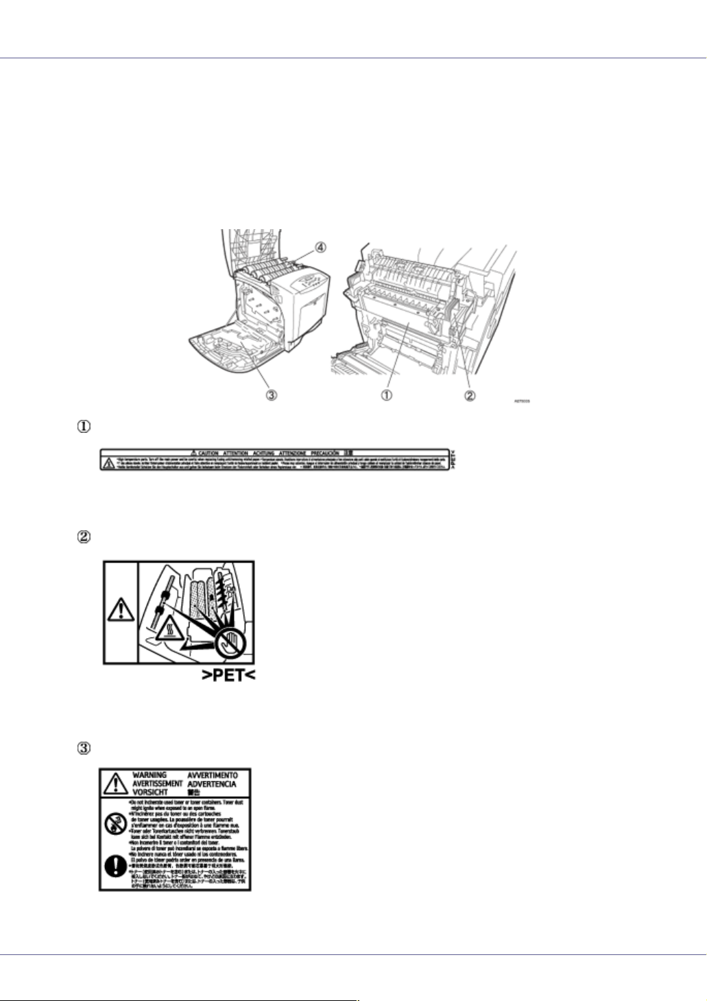
Positions of RWARNING and RCAUTION
labels
This machine has labels for RWARNING and RCAUTION at the positions
shown below. For safety, please follow the instructions and handle the machine
as indicated.
High temperature parts. Turn off the main power and be careful when replacing
fusing unit / removing misfed paper.
The inside of this printer becomes very hot. Do not touch parts labelled “v” (indicating a hot surface). Touching these parts will result in burns.
8
Page 9

Read This First
Do not incinerate used toner or toner containers. Toner dust might ignite when
exposed to an open flame.
Do not incinerate spilled toner or used toner. Toner dust is flammable and might
ignite when exposed to an open flame.
Disposal should take place at an authorized dealer or an appropriate collection
site.
If you dispose of the used toner containers yourself, dispose of them according
to local regulations.
9
Page 10

Read This First
ENERGY STAR Program
As an ENERGY STAR Partner, we have determined that this machine model meets the ENERGY STAR Guidelines for energy efficiency.
The ENERGY STAR Guidelines intend to establish an international energy-saving system for
developing and introducing energy-efficient office equipment to deal with environmental issues,
such as global warming.
When a product meets the ENERGY STAR Guidelines for energy efficiency, the Partner shall
place the ENERGY STAR logo onto the machine model.
This product was designed to reduce the environmental impact associated with office equipment by means of energy-saving features, such as Low-power mode.
❖ Low-power Mode (Energy Saver mode)
This printer automatically lowers its power consumption 30 minutes after the
last operation has been completed. To exit Low-power (Energy Saver) mode,
press any key on the control panel. For more information about how to configure Energy Saver mode, see “Making Printer Settings with Control Panel”,
Software Guide as a HTML file on the CD-ROM.
❖ Specifications
Energy Saver mode Power Consumption 6 W or less
Default Time 30 minutes
Recovery Time 30 seconds or less
10
Page 11

Read This First
How to Read This Manual
The following set of symbols is used in this manual.
This symbol indicates a potentially hazardous situation that might result in death
or serious injury when you misuse the machine without following the instructions
under this symbol. Be sure to read the instructions, all of which are described in
the Safety Information section.
This symbol indicates a potentially hazardous situation that might result in minor
or moderate injury or property damage that does not involve personal injury
when you misuse the machine without following the instructions under this symbol. Be sure to read the instructions, all of which are described in the Safety Information section.
* The statements above are notes for your safety.
If this instruction is not followed, paper might be misfed, originals might be damaged, or data might be lost. Be sure to read this.
This symbol indicates information or preparations required prior to operating.
This symbol indicates precautions for operation, or actions to take after abnormal
operation.
This symbol indicates numerical limits, functions that cannot be used together,
or conditions in which a particular function cannot be used.
This symbol indicates a reference.
[ ]
Keys that appear on the machine's display.
Keys and buttons that appear on the computer's display.
{ }
Keys built into the machine's control panel.
Keys on the computer's keyboard.
11
Page 12

Guide to the Printer
Exterior: Front View
1. Control Panel
Contains keys for printer control and a display that shows the printer status.
2. Front Cover
Open the front cover to replace the fusing unit or transfer roller, or to remove jammed
paper.
The front cover can be opened in two ways:
To replace the fusing unit or roller, pull the levers marked “A” on either side of the ma-
chine. To remove jammed paper, press the button marked “Z” on the right side of the
machine.
3. Bypass Tray
Up to 100 sheets of plain paper can be loaded.
❒ When setting paper larger than A5 K, pull out the paper support tray as shown in the
drawing. For information on the sizes and types of paper that can be used, see Maintenance Guide.
G1058604A_1.10 Copyright © 2004, 2005 12
Page 13

Guide to the Printer
4. Power Switch
Use this switch to turn the power on and off.
5. Tray 1
Up to 550 sheets of plain paper can be loaded.
6. Standard Tray
Output is stacked here with the print side down.
7. Top Cover
Open this cover when replacing the toner cartridge.
8. Front Cover (A) Open Levers
9. Vent
10. Ventilator
Releases heat from internal components to prevent overheating. Malfunctions occur if
the vent is blocked or obstructed.
11. Front Cover (Z) Open Button
13
Page 14

Guide to the Printer
Exterior: Rear View
1. Controller Board
Slide this out to install options such as the memory unit, user account enhance unit or
printer hard disk. Plug cables such as the USB cable and Ethernet cable into their connectors.
2. Ethernet Port
Use a network interface cable to connect the printer to the network.
3. USB Port
Use a USB cable to connect the printer to the host computer.
4. Optional Interface Board Slots
Insert an optional 1394 interface board, 802.11b interface unit, wireless interface board,
or 1284 interface board in this slot. Up to two interface board can be inserted at a time.
5. Expansion Card Slots
Install expansion cards in these slots. There are three slots.
When you use the expansion card, use the centre slot.
6. Front Cover (A) Open Levers
7. Left Cover
Open this cover when replacing the photo conductor unit (PCU), intermediate transfer
unit or waste toner cartridge.
8. Power Cable
14
Page 15

Guide to the Printer
Inside
1. Toner Cartridge
Loads from the printer rear, in the order of yellow (Y), cyan (C), magenta (M), and black
(K).
When “Add Toner XXX” appears on the display, replace the indicated color of the toner
cartridge.
❒ The color is displayed for XXX.
2. Intermediate Transfer Unit (Transfer Unit)
When “Replace Transfer Unit” appears on the display, replace the transfer unit .
3. Photo Conductor Unit
When “Replace Black PCU” or “Replace Color PCU” appears on the display, replace the
photo conductor unit.
4. Inner Cover
Open this when replacing the photo conductor units or intermediate transfer unit.
5. Waste Toner Bottle
Collects toner that is wasted during printing.
When “Replace Waste Toner bottle” appears on the display, replace the waste toner bot-
tle.
6. Fusing Unit
When “Replace Maintenance Kit” appears on the display, replace the fusing unit.
7. Transfer Roller
When “Replace Maintenance Kit” appears on the display, replace the transfer roller.
15
Page 16

Guide to the Printer
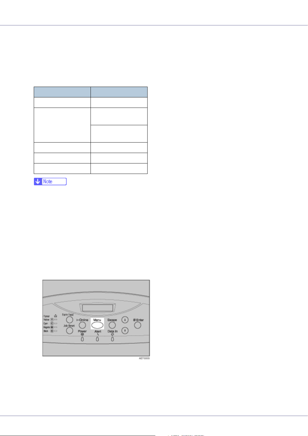
Control Panel
1. Display
Displays current printer status and error messages.
For details about error messages, see Maintenance Guide.
2. {Menu} key
Press this key to make and check the current printer settings.
For details, See “Making Printer Settings Using the Control Panel”, Software Guide.
3. Toner End LED
The color of the lit LED indicates the toner status for each color.
A yellow light indicates that the toner amount is approaching exhaustion, and the red
light indicates that the toner cartridge needs to be replaced.
4. {Form Feed} key
When the printer is offline, press this to print all data left in the printer's input buffer.
You can use this to force the printer to print data received in the online status when the
paper size or type does not match the actually set size or type.
5. {Job Reset} key
When the printer is online, press this key to cancel an ongoing print job.
6. {Online} key
Indicates whether the printer is online or offline. Press this to switch between online and
offline.
When the lamp is lit, the printer is online, enabling data reception from the host computer.
When the lamp is unlit, the printer is offline, disabling data reception from the host computer.
Press to return to the ready condition.
7. Power indicator
This indicator remains lit while the power is on. It is unlit when the power is off or while
the printer is in Energy Saver mode.
8. Alert indicator
Lights up whenever a printer error occurs. A red light indicates an error has occurred that
makes printing impossible; the yellow light indicates a potential error during printing.
16
Page 17

Guide to the Printer
If the red light is on, follow the instructions that appear on the display.
9. Data In indicator
Blinks when the printer is receiving data from a computer. The Data In indicator is lit if
there is data to be printed.
10. {Escape} key
Press this key to return to the previous condition on the display.
11. {U} {T} keys
Use these keys to increase or decrease values on the display when making settings.
Keep the key pressed to quicken scrolling, and increase or decrease values on the dis-
play in units of 10.
12. {# Enter} key
Press this key to execute menu items selected on the display.
17
Page 18

Setting Up
Where to Put the Printer
The printer's location should be carefully chosen because environmental conditions greatly affect its performance.
• Confirm the wall outlet is near the machine and freely accessible, so
that in the event of emergency, it can be unplugged easily.
• Only connect the machine to the power source described in the manual.
• Avoid multi-wiring.
• Do not damage, break or make any modifications to the power cord.
Do not place heavy objects on it, pull it hard or bend it more than necessary. These actions could cause an electric shock or fire.
• Do not handle the plug with wet hands. Doing so might cause an electrical
shock.
• Keep the machine in an area that is within optimum environmental conditions. Operating the machine in an environment that is outside the recommended ranges of humidity and temperature can cause an electrical fire
hazard. Keep the area around the socket free of dust. Accumulated dust
can become an electrical fire hazard.
• Place the machine on a strong and level surface. Otherwise, it might fall and
injure someone.
• If you use the machine in a confined space, ensure there is continuous air
circulation.
❖ Space Required for Installation
Leave enough space around the printer. This space is necessary to operate
the printer. The recommended (or minimum) space requirements are as follows:
A: 50 cm (19.7 inches) or more
G1058604A_1.10 Copyright © 2004, 2005 18
Page 19
Setting Up
B: 10 cm (4 inches) or more
C: 10 cm (4 inches) or more
D: 70 cm (27.6 inches) or more
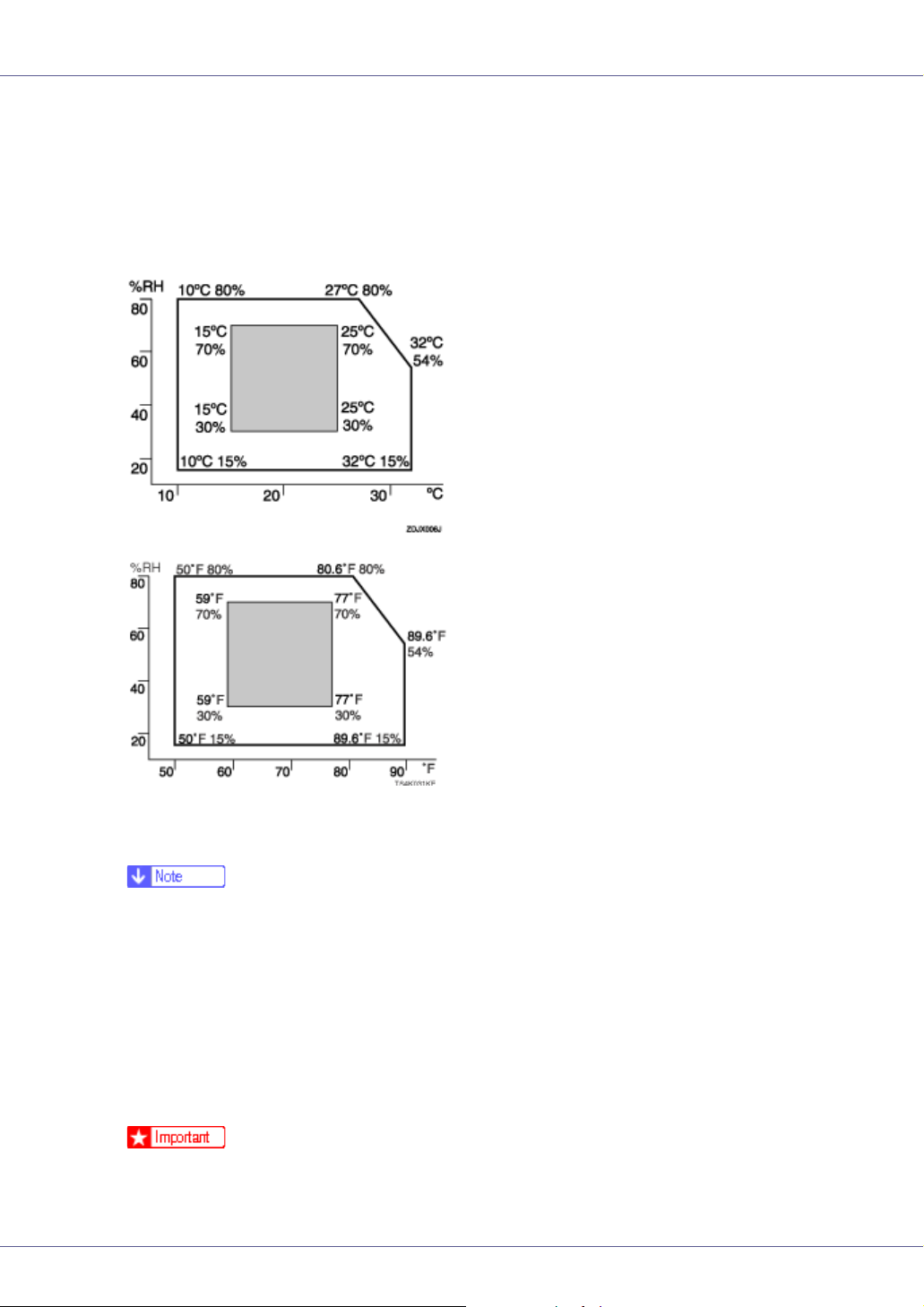
❖ Optimum Environmental Conditions
Permissible and recommended temperature and humidity ranges are as follows:
• White area: Permissible Range
• Gray area: Recommended Range
❒ The machine must be level within 5 mm, 0.2” from both front to rear and left
to right.
❒ To avoid possible build-up of ozone, locate this machine in a large well ven-
tilated room that has an air turnover of more than 30 m
3
/hr/person.
❒ When you use this machine for a long time in a confined space without
good ventilation, you may detect an odd smell. To keep the workplace
comfortable, we recommend you keep it well ventilated.
❖ Environments to Avoid
❒ Areas exposed to direct sunlight or strong light
❒ Dusty areas
19
Page 20

Setting Up
❒ Areas with corrosive gases
❒ Areas that are excessively cold, hot, or humid
❒ Locations near air conditioners or humidifiers
❒ Locations near other electronic equipment
❒ Locations subject to frequent strong vibration
❖ Power Source
Connect the power cable to a power source of the following specification:
• 220 - 240 V, 50/60 Hz, 6 A or more
20
Page 21

Setting Up
Checking the Contents of the Box
Follow the procedure below to verify the items that come with the printer.
❒ Ensure that the box contains all items listed below. If there are any missing or
defective items, contact your sales representative.
❖ Manuals and CD-ROMs
Setup Guide (This manual)
Maintenance Guide
CD-ROM “Printer Drivers and Utilities”
CD-ROM “Display-Version Manuals (HTML)”
CD-ROM “Print-Version Manuals (PDF)”
CD-ROM “Document Management Utility”
❖ Parts
Ferrite Core × 2
Toner Cartridges: Black (K), Magenta (M), Cyan (C), Yellow (Y)
21
Page 22

Setting Up
Paper Feed Unit Labels
Color Calibration Sample Sheet
Additional Documentation
❒ This package does not include an interface cable. Please purchase one to use
with your host computer. See “Appendix”, Maintenance Guide.
22
Page 23

Setting Up
Unpacking
To protect it from shock and vibration during transit, this printer comes packaged
in cushioning foam and secured with tape. Remove these protective materials
after bringing the machine to where it will be installed.
• When lifting the machine, use the inset grips on both sides. The printer
could break or cause an injury if dropped.
• Place no objects on the left or inner cover.
❒ Be sure to remove all four strips of tape from the photo conductor unit to avoid
malfunction.
❒ Removed tape is dirty. Be careful not to let it touch your hands or clothes.
A Remove the plastic bag.
B Lift the printer with two people by using the inset grips on both sides of
the printer.
❒ Leave the tape holding the paper feed tray and cover in place while moving
the printer.
❒ Lower the machine slowly and carefully to prevent trapping your hands.
C Remove the orange adhesive tape from the printer body.
23
Page 24
Setting Up
D Open the left cover. Do not remove the orange tape attached to the left
cover.
E Turn the two green levers counterclockwise ( ), and then slowly open
the inner cover ( ).
F Remove the end of the tape from the printer.
24
Page 25

Setting Up
G Remove the four pieces of tape from the photo conductor unit.
H Remove the securing pin, as shown, from the transfer unit. Pinch it, and
then pull it out.
I Turn the green lever of the transfer unit counterclockwise to unlock the
unit.
25
Page 26

Setting Up
J Remove the protective sheet, as shown. Pinch the orange tape, and then
pull it out.
K Turn the green lever clockwise to lock the unit.
L Close the inner cover. Lock the inner cover by pressing in ( ) and then
turning the two green levers clockwise ( ).
M Close the left cover.
Close the left cover firmly using both hands, until it clicks into place.
26
Page 27

Setting Up
N Open the top cover by grasping the handles on the left and right sides.
O Remove the clips protecting the mouths of all four toner cartridges.
P Close the top cover.
Q Put labels “1” on the front of the paper tray.
27
Page 28

Setting Up
R Attach the supplied sticker, which warns users that ink-jet printer paper
cannot be use with this printer, to the front of the machine.
28
Page 29

Setting Up
Installing the Toner Cartridge
The following procedure describes how to install the toner cartridge.
• Do not incinerate spilled toner or used toner. Toner dust is flammable
and might ignite when exposed to an open flame.
• Disposal should take place at an authorized dealer or an appropriate
collection site.
• If you dispose of the used toner cartridges yourself, dispose of them
according to local regulations.
• Do not store toner, used toner, or toner containers in a place with an
open flame. The toner might ignite and cause burns or a fire.
• Keep toner (used or unused) and the toner cartridge out of reach of children.
• If toner or used toner is inhaled, gargle with plenty of water and move into
a fresh air environment. Consult a doctor if necessary.
• If your skin comes into contact with toner or used toner, wash the affected
area thoroughly with soap and water.
• If toner or used toner gets into your eyes, flush immediately with large
amounts of water. Consult a doctor if necessary.
• If toner or used toner is swallowed, dilute by drinking a large amount of water. Consult a doctor if necessary
• Avoid getting toner on your clothes or skin when removing a paper jam or
replacing toner. If your skin comes into contact with toner, wash the affected
area thoroughly with soap and water.
• If toner gets on your clothing, wash with cold water. Hot water will set the
toner into the fabric and may make removing the stain impossible.
❒ When you first use this printer, use the four toner cartridges packaged with the
printer.
❒ The toner cartridges that comes with the printer will allow you to print up to
about 3,000 pages. These numbers were obtained from printing A4 K5%
charts, but the actual number of pages will vary depending on the paper type,
size, contents, and settings.
❒ The toner cartridge for replacement comes in two types for different number
of printable pages: 15,000 pages and 5,000 pages.
29
Page 30
Setting Up
❒ Toner Cartridges (consumable) are not covered by warranty. However, if
there is problem, contact the store where they ware purchased.
❒ Toner cartridge mouths may be dirtied during quality inspection.
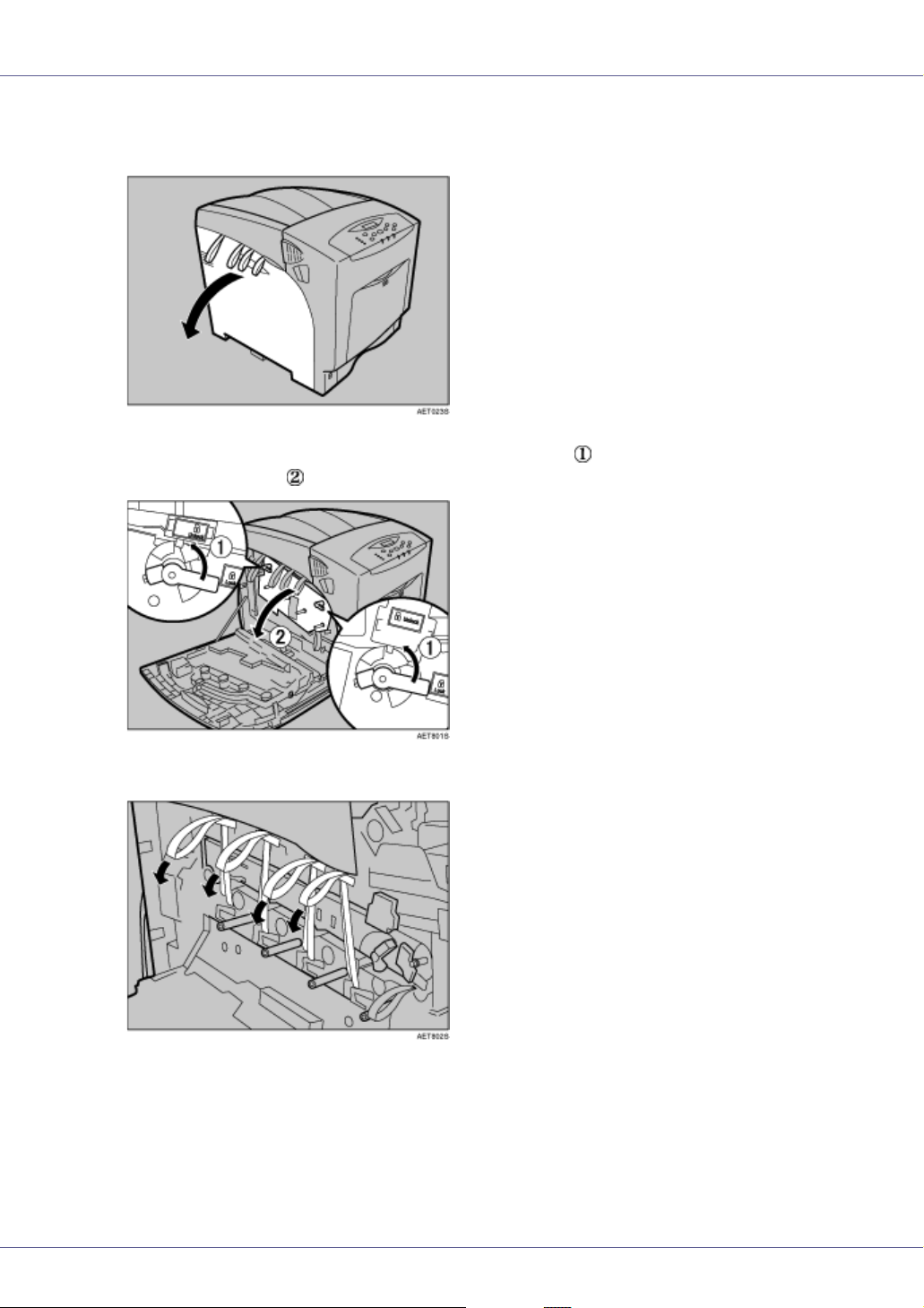
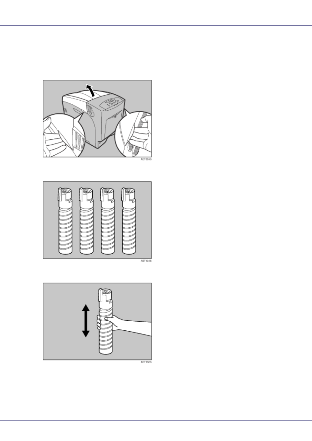
A Open the top cover.
B Take the toner cartridges out of the box.
C Shake the toner cartridge up and down seven or eight times.
30
Page 31

Setting Up
D Remove the tape holding the toner cartridge.
E First, install the yellow toner cartridge. Holding the toner cartridge hor-
izontally ( ) with the locking lever on the upper side, install the toner
cartridge bottom first, and then move the locking lever to the triangle
mark ( ).
F Turn the locking lever to the circle mark. Pull the locking lever toward
you, until it locks into place.
❒ Do not repeatedly insert and remove toner cartridges. Doing so results in
toner leakage.
31
Page 32

Setting Up
G Use the same procedures to insert the remaining three toner cartridges:
cyan (C), magenta (M), and black (K).
H Close the top cover.
❒ Do not turn off the power switch while “Loading Toner...” appears on the
display. Doing so results in malfunction.
32
Page 33

Setting Up
Loading Paper
The following describes how to load paper into the standard paper tray (Tray 1).
• Do not pull out the paper tray forcefully. If you do, the tray might fall and
cause an injury.
❒ To avoid paper jams, make sure paper is not stacked above the limit mark in-
side the tray. Misfeeds might occur.
❒ Do not mix different types of paper in a single paper tray.
A Slowly slide out the paper tray (Tray1), until it stops. Then, lift it slightly,
and then pull it out completely.
Place it on a flat surface.
B Pinch the green clips of the side guide and the end guide and adjust the
guides to the paper size being loaded.
33
Page 34

Setting Up
C Slide the green switch on the front of the tray to the type of paper to be
loaded. When loading paper of 75 g/m
to the right.
2
, 20 lb., or thicker, slide the switch
D Load the new paper stack print side up, making sure the paper is flush
against the paper guides. Adjust the paper guides to close any gaps.
E Lift the front of the paper tray (Tray 1), and slowly slide the paper tray
back, until it stops. Make sure the tray is fully inserted to prevent paper
jams.
For details about usable types of paper, see “Loading Paper”, Maintenance
Guide.
34
Page 35

Setting Up
Turning the Power On
Follow the procedure below to turn the power on.
• Plug and unplug the power cable with dry hands, or an electric shock
could occur.
A Make sure the power switch is set to “b” Off.
B Plug in the power cable.
❒ Make sure the power cable is plugged securely into the wall outlet.
❒ Turn the power switch off when plugging and unplugging the power plug.
C Turn the power switch to “a” On.
The power indicator on the control panel lights up.
❒ Wait until “Ready” appears on the display panel.
❒ The machine may make a noise while initializing. This noise does not indi-
cate a malfunction.
35
Page 36

Setting Up
❒ Do not turn off the power switch until initializing is completed. Doing so re-
sults in malfunction.
36
Page 37
Setting Up
Selecting the Display Language
Select a language using the procedure described here.
The message for the selected language will appear on the display. If you want to
use the display in English, the following procedures are unnecessary.
❒ The default setting is English.
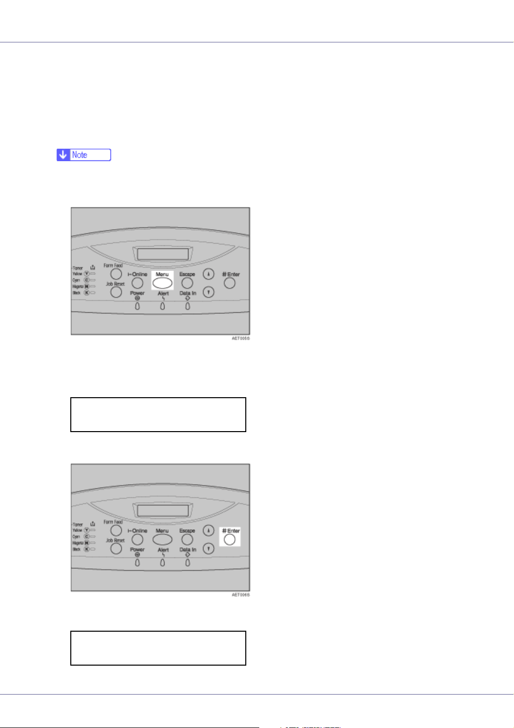
A Press the {Menu} key.
The “Menu” appears on the display.
B Press the {U} or {T} key to display “Language”.
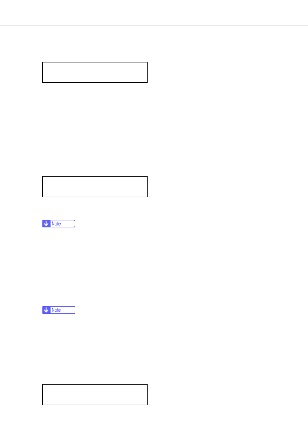
Menu:
Language
C Press the {# Enter} key.
The following message appears on the display:
Language:
*English
37
Page 38

Setting Up
D Press the {U} or {T} key until the language you want to select appears.
E Press the {# Enter} key. Wait for two seconds.
“Menu” appears on the display.
F Press the {Online} key.
“Ready” message appears on the display.
Ready
38
Page 39

Setting Up
Test Printing
The following explains the procedure for test printing of the configuration page.
Test print in order to verify that the printer is working normally. Test printing
checks printer performance only; it does not test the connection to the computer.
A Press the {Menu} key.
“Menu” appears on the display.
Menu:
Paper Input
B Press the {U} or {T} key to display “List/Test Print”, and then press the
{# Enter} key.
Menu:
List/Test Print
The menu for selecting the contents to be test printed appears.
C Press the {U} or {T} key to display the “Config. Page”, and then press
the {# Enter} key.
List/Test Print:
Config. Page
The following message appears and the configuration page is printed.
Printing...
39
Page 40

Setting Up
❒ If printing is not normal, check to see if an error message appears on the
display. If there is an error message, see “Troubleshooting”, Maintenance
Guide.
D Check the options.
❒ For details about the configuration page, see “Interpreting the Configura-
tion Page”, Software Guide.
E Press the {Online} key.
“Ready” message appears on the display.
Ready
40
Page 41

Installing Options
Available Options
This section describes how to install options.
By installing options, you can improve the printer performance and have an expanded variety of features to use. For the specifications of each option, see
Maintenance Guide.
• Before installing options, the machine should be turned off and unplugged
for at least an hour. Components inside the machine become very hot, and
can cause a burn if touched.
• Before moving the machine, unplug the power cable from the outlet. If the
cable is unplugged abruptly, it could become damaged. Damaged plugs or
cables can cause an electrical or fire hazard.
• When lifting the machine, use the grips on both sides. The machine could
break or cause an injury if dropped.
❒ The voltage rating of the connector for options is 24 V DC or less.
Option List
The following is a list of options for this printer. Some printer models come with
the expansion Hard Disk Drive and Network Data Protection Unit installed as default.
Basic model printer HDD standard model printer
Paper Feed Unit Type 4000
Hard Disk Drive Type 4000
Memory Unit Type D 128MB
Memory Unit Type E 256MB
IEEE 802.11b Interface Unit
Type H
IEEE 1284 Interface Board
Type A
IEEE 1394 Interface Board
Type B
Bluetooth Interface Unit Type
3245
User Account Enhance Unit
Type E
G1058604A_1.10 Copyright © 2004, 2005 41
Page 42

Installing Options
Basic model printer HDD standard model printer
Network Data Protection Unit
Type B
: Available option
Option Installation Flow Chart
We recommend you install multiple options in the following order:
A Attach the paper feed unit ( Paper Feed Unit Type 4000 ).
Attach the paper feed unit to the bottom of the printer.
You can attach up to two paper feed unit. Up to 1750 sheets of paper can be
loaded.
B Install the SDRAM module ( Memory Unit Type D 128MB, Memory Unit
Type E 256MB ).
Install the module to the SDRAM module slot on the controller board.
There are two types of memory unit: 128 MB and 256 MB.
C Install the user account enhance unit ( User Account Enhance Unit Type
E ).
Install the module to the user account enhance unit slot of the controller
board.
D Install the hard disk drive ( Hard Disk Drive Type 4000 ).
Install the hard disk drive to the controller board.
E Install the IEEE 1394 interface board, IEEE 1284 interface board, IEEE
802.11b interface unit or Bluetooth interface unit.
Install the IEEE 1394 interface board, IEEE 1284 interface board, IEEE
802.11b interface unit or Bluetooth interface unit on the controller board.
The IEEE 1394 interface board and standard Ethernet interface cannot be
used at the same time.
Up to two of the following can be installed:
• IEEE 1394 Interface Board Type B
• IEEE 1284 Interface Board Type A
• IEEE 802.11b Interface Unit Type H
• Bluetooth Interface Unit Type 3245
F Install the network data protection unit ( Network Data Protection Unit
Type B ).
Insert the network data protection unit into the SD card slot on the controller
board.
42
Page 43

Installing Options
Installing Options
Install options in the positions shown in the illustration.
❖ Exterior
1. Paper Feed Unit Type 4000
Loads up to 550 sheets of paper.
Up to two paper feed units, can be installed on the printer. Installed tray units are
identified as “Tray 2” and “Tray 3”.
See p.46 “
❖ Interior
Attaching Paper Feed Unit Type 4000”.
43
Page 44

Installing Options
1. Memory Unit Type D 128MB/Memory Unit Type E 256MB (SDRAM mod-
ule)
Install 128 MB or 256 MB SDRAM module into the controller board slot.
See p.49 “
(SDRAM Module)”
Attaching Memory Unit Type D 128MB, Memory Unit Type E 256MB
2. IEEE 1394 Interface Board Type B / IEEE 802.11b Interface Unit Type H
/ Bluetooth Interface Unit Type 3245 / IEEE 1284 Interface Board Type A
See p.67 “Attaching IEEE 1394 Interface Board Type B”
See p.70 “
See p.74 “
See p.78 “
Attaching IEEE 802.11b Interface Unit Type H”
Attaching Bluetooth Interface Unit Type 3245”
Attaching IEEE 1284 Interface Board Type A”
3. Network Data Protection Unit Type B
See p.80 “Attaching Network Data Protection Unit Type B”
4. Hard Disk Drive Type 4000
See p.60 “Attaching Hard Disk Drive Type 4000”
5. User Account Enhance Unit Type E
See p.55 “Attaching User Account Enhance Unit Type E”
❒ You can have two of the following types of extension board installed at the
same time: IEEE 1394 Interface Board Type B, IEEE 802.11b Interface Unit
Type H, Bluetooth Interface Unit Type 3245, IEEE 1284 Interface Board Type
A.
❒ Some printer models come with the expansion Hard Disk Drive Unit and Net-
work Data Protection Unit installed as default.
For the specifications of each option, see Maintenance Guide.
Caution when re-installing the controller board
This section describes handling the controller board when installing options.
If you slide out the controller board to install the SDRAM module, the user account enhance unit, or the printer hard disk, carefully follow the instruction below
to re-install the controller board.
44
Page 45
Installing Options
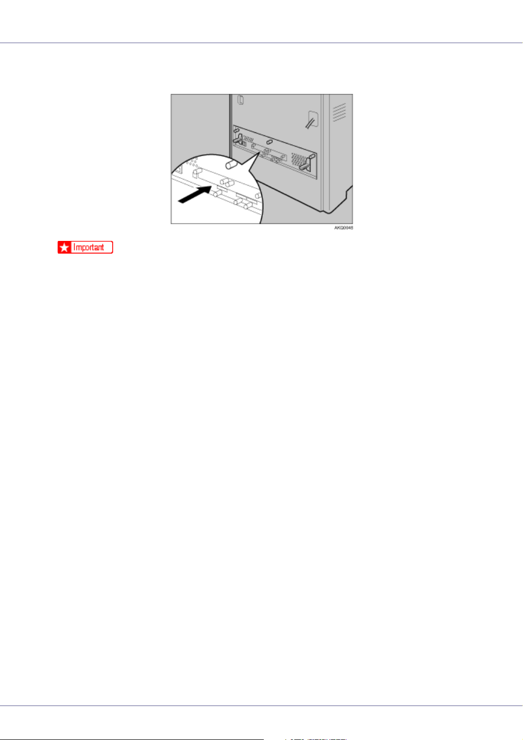
• Re-install the controller board into the machine by pushing the bottom center
area of the board, as shown in the illustration.
❒ The following may occur if the controller board is not properly installed:
• all control panel indicators light
• no control panel indicators light
• the “SC670” error message appears on the display
45
Page 46

Installing Options
Attaching Paper Feed Unit Type 4000
When installing multiple options, install the paper feed unit first.
• The printer weights approximately 50 kg (110.3 lb.). When moving the print-
er, use the inset grips on both sides, and lift slowly. The printer will break or
cause injury if dropped.
• Lifting the paper feed unit carelessly or dropping it may cause injury.
❒ Up to two paper feed units can be attached to the printer.
❒ When two paper feed units are installed, they are identified as “Tray 2” and
“Tray 3” starting from the upper unit.
❒ Before using the new Paper Feed Unit, you must make settings in the printer
driver.
❒ Check the printer nameplate to confirm the model code.
A Check the package contains the following:
❖ Paper Feed Unit (including a paper tray)
B Turn off the power, and then unplug the power cable.
C Remove the orange fastening tapes from the paper feed unit.
46
Page 47

Installing Options
D Lift the printer using the inset grips on both sides of the printer.
❒ The printer should always be lifted by at least two people.
E Align the printer with the two upright pins on the paper feed unit and
then lower the printer slowly.
When installing two paper feed units, connect the two units first using the
same procedure below before connecting the units to the printer.
❒ When moving the printer, remove the paper feed unit.
47
Page 48

Installing Options
❒ After finishing installation, you can check whether the paper feed unit is
properly installed: Print the configuration page from the “List/Test Print”
menu. If it is installed properly, you will see “Tray 2” or “Tray 2, Tray 3” under the “Options” list.
❒ If the paper feed unit is not installed properly, reinstall it from step
cannot install it properly even after attempting reinstallation, contact your
sales or service representative.
For printing the configuration page, see p.39 “Test Printing”.
See “Loading Paper”, Maintenance Guide.
When adjusting the printing position, see “Adjusting Tray Registration”,
Maintenance Guide.
B
. If you
48
Page 49

Installing Options
Attaching Memory Unit Type D 128MB,
Memory Unit Type E 256MB (SDRAM
Module)
• Do not touch the inside of the controller board compartment. Doing so may
cause a malfunction or a burn.
❒ Before touching the memory unit, ground yourself by touching something met-
al to discharge any static electricity. Static electricity can damage the memory
unit.
❒ Do not subject the memory unit to physical shocks.
❒ Available memory varies depending on model type.
❒ Before using the new memory unit, you must make settings in the printer driv-
er.
A Turn off the power, and then unplug the power cable.
B Loosen the three screws securing the controller board.
The screws cannot be fully removed.
49
Page 50

Installing Options
C Grasp the handles and carefully pull out the controller board.
Using both hands, slide the controller board completely out.
D Place the controller board on a flat surface, and then loosen the four
screws to remove the cover.
The screws cannot be fully removed.
50
Page 51

Installing Options
E You must install the SDRAM module as shown.
❒ Two slots are provided for the SDRAM modules. The default SDRAM mod-
ule is installed in the inner slot. To install additional memory, attach an additional SDRAM module to the outer slot, or replace the default SDRAM
module.
F When installing an SDRAM module in a vacant slot, align the notch of
the SDRAM module with the slot, and then insert the module vertically.
G Press down the SDRAM module, until it clicks into place.
51
Page 52

Installing Options
H When replacing the default SDRAM module, press down the levers on
both sides ( ) to remove the default module ( ).
Install a new SDRAM module.
❒ To increase memory capacity to the maximum of 512 MB, remove the de-
fault SDRAM module, and then install two 256 MB SDRAM modules.
I To install other options on the controller board, follow the appropriate
installation procedure(s), and then screw down the controller board
cover.
J Fasten the four screws to attach the cover.
52
Page 53

Installing Options
K Align the controller board with the left and right rails, and then push it
carefully in, until it stops.
❒ The printer may malfunction if the controller board is not properly installed.
L Fasten the controller board to the printer using the three screws.
❒ Be sure to return the provided screwdriver to its original position on the in-
side of the front cover.
❒ After finishing the installation, you can check the memory unit is properly
installed: Print the configuration page from the “List/Test Print” menu. If it
is installed properly, you will see the memory capacity for “Total Memory”.
❒ The table below shows total SDRAM module capacities.
Standard Extended Total
128 MB 128 MB 256 MB
128 MB 256 MB 384 MB
256 MB 128 MB 384 MB
256 MB 256 MB 512 MB
53
Page 54

Installing Options
❒ If the memory unit is not properly installed, repeat the procedure from step
. If you cannot install it properly even after reinstallation, contact your
A
sales or service representative.
For printing the configuration page, see p.39 “Test Printing”.
Install the controller board carefully. For details, see p.44 “
re-installing the controller board”.
Caution when
54
Page 55

Installing Options
Attaching User Account Enhance Unit
Type E
• Do not touch the inside of the controller board compartment. Doing so may
cause a malfunction or a burn.
❒ Before touching the User Account Enhance Unit, ground yourself by touching
something metal to discharge any static electricity. Static electricity can damage the User Account Enhance Unit.
❒ Do not subject the User Account Enhance Unit to physical shocks.
A Check the package contains the following:
❖ User Account Enhance Unit Type E
B Turn off the power, and then unplug the power cable.
C Loosen the three screws securing the controller board.
The screws cannot be fully removed.
55
Page 56

Installing Options
D Grasp the handles, and then pull the controller board carefully out.
Using both hands, slide the controller board completely out.
E Place the controller board on a flat surface. Loosen the five screws to
remove the cover
The screws cannot be fully removed.
56
Page 57

Installing Options
F You must install the User Account Enhance Unit as shown.
G Align the notch of the user account enhance unit, and then insert it into
the controller board, pressing it down until it clicks into place.
H Make sure that the user account enhance unit is firmly connected to the
controller board.
57
Page 58
Installing Options
I Fasten the four screws to attach the cover.
J Align the controller board with the left and right rails, and then push it
carefully in, until it stops.
❒ The printer may malfunction if the controller board is not properly installed.
K Fasten the controller board to the printer using the three screws.
❒ After finishing installation, you can check the User Account Enhance Unit
is properly installed: Print the configuration page from the “List/Test Print”
menu. If it is installed properly, you will see “Accounting Module” for “Controller Option”.
58
Page 59

Installing Options
❒ If the User Account Enhance Unit is not installed properly, reinstall it from
step
contact your sales or service representative.
For printing the configuration page, see p.39 “Test Printing”.
Install the controller board carefully. For details, see p.44 “
re-installing the controller board”.
. If you cannot install it properly even after attempting reinstallation,
A
Caution when
59
Page 60

Installing Options
Attaching Hard Disk Drive Type 4000
• Do not touch the inside of the controller board compartment. Doing so may
cause a machine malfunction or a burn.
❒ Before touching the hard disk drive, touch something metal to discharge any
static electricity. Static electricity can damage the hard disk drive.
❒ Do not subject the hard disk drive to physical shocks.
❒ Before using the new hard disk drive, you must make the settings in the printer
driver.
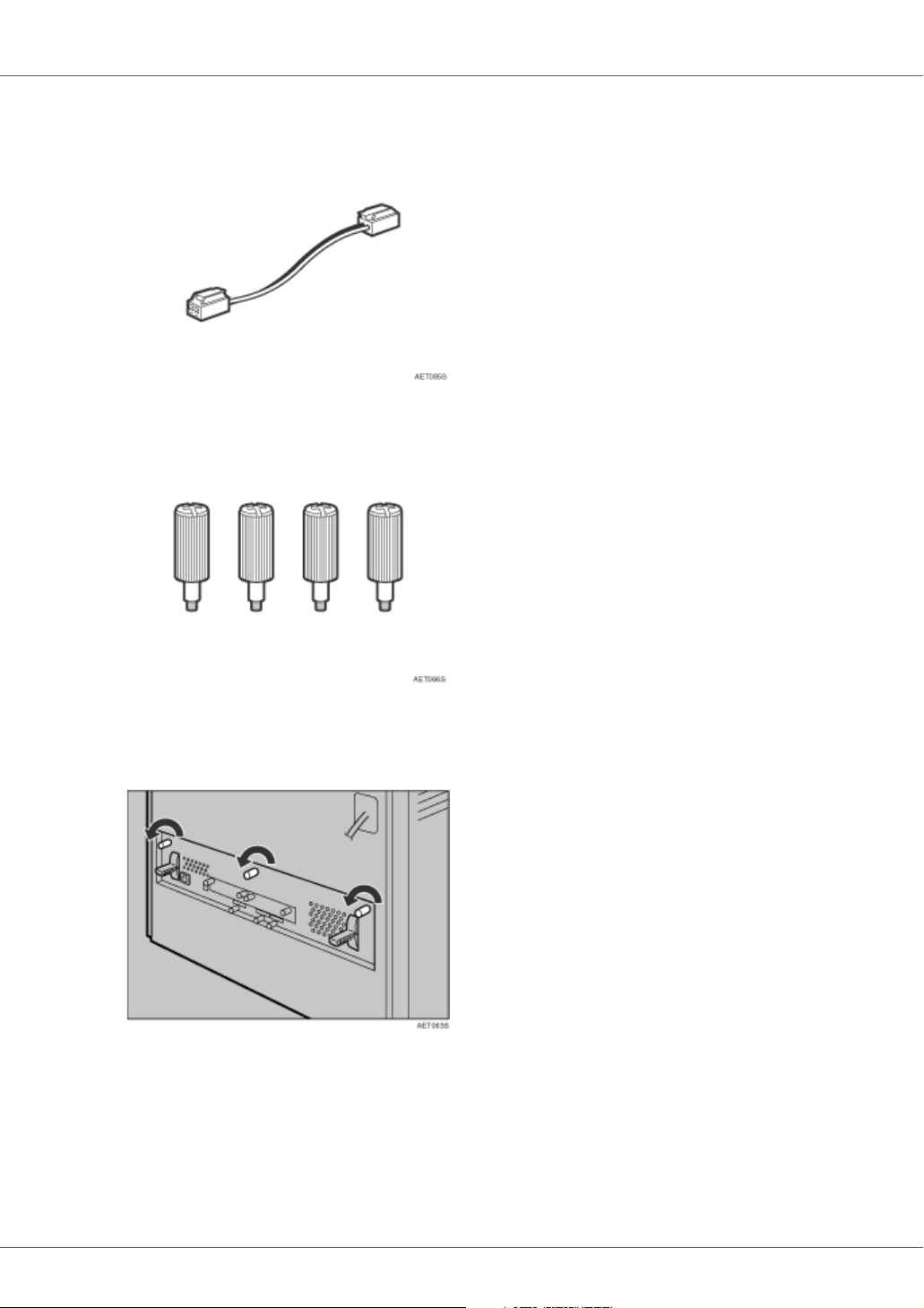
A Check the package contains the following:
❖ Hard Disk Drive
❖ Flat Cable
60
Page 61
Installing Options
❖ Power Cable
❖ Four Screws
B Turn off the power, and then unplug the power cable.
C Loosen the three screws securing the controller board.
The screws cannot be fully removed.
61
Page 62

Installing Options
D Grasp the handles, and then pull the controller board carefully out.
Using both hands, slide the controller board completely out.
E Place the controller board on a flat surface, and then loosen the four
screws to remove the cover.
The screws cannot be fully removed.
62
Page 63
Installing Options
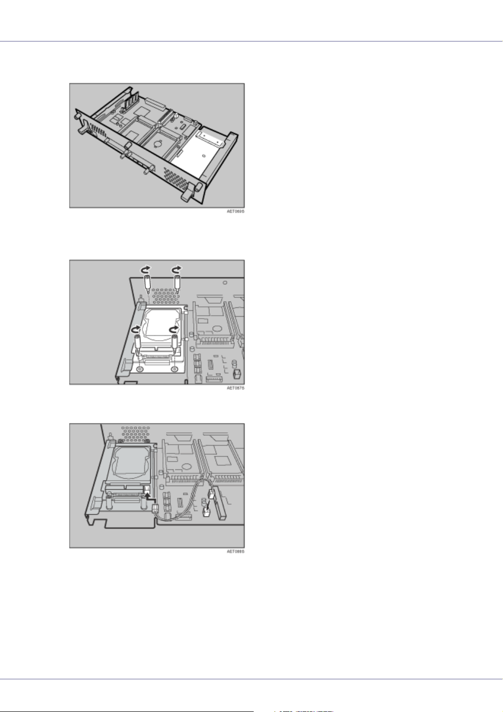
F You must install the hard disk drive unit as shown.
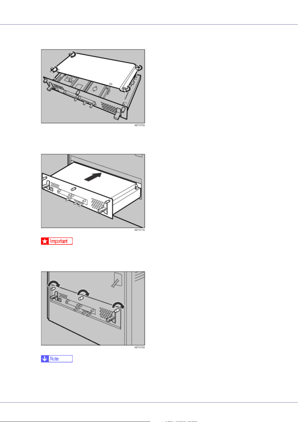
G Use the screws supplied with the hard disk drive to secure the unit to
the controller board.
H Connect the power cable to the hard disk drive and controller board.
63
Page 64

Installing Options
I Connect the flat cable to the hard disk drive and the controller board.
Connect the blue end of the flat cable to the controller board.
J When installing other options on the controller board, do not close the
controller board, but go to the steps for installing the option.
K Fasten the four screws to attach the cover.
L Align the controller board with the left and right rails, and then push it
carefully in, until it stops.
❒ The printer may malfunction if the controller board is not properly installed.
64
Page 65

Installing Options
M Fasten the controller board to the printer using the three screws.
When the power is turned on, the hard disk drive will be formatted automatically.
❒ After finishing installation, you can check whether the hard disk drive is
properly installed: Print the configuration page from the “List/Test Print”
menu. If it is installed properly, you will see “Printer Hard Disk Drive” for
“Controller Option”.
❒ If the hard disk drive is not installed properly, reinstall it from step
cannot install it properly even after attempting reinstallation, contact your
sales or service representative.
A
. If you
For printing the configuration page, see p.39 “Test Printing”.
Install the controller board carefully. board. For details, see p.44 “
when re-installing the controller board”.
Caution
Formatting the Hard Disk Drive
If it becomes necessary to format the hard disk drive after initial setup, execute
“HD Format” in the “Maintenance” menu.
❒ Formatting the hard disk drive will delete all data.
65
Page 66

Installing Options
A Press the {Menu} key.
“Menu” appears on the display.
B Press the {U} or {T} key to display “Maintenance”, and then press the
{# Enter} key.
Menu:
Maintenance
The menu for selecting “Maintenance” items appears.
C Press the {U} or {T} key to display “HD Format”, and then press the {#
Enter} key.
A check message appears.
❒ If “HD Format” is not displayed on the display, the hard disk drive is not in-
stalled properly. Repeat the procedure from step
Hard Disk Drive Type 4000”. If you still cannot install it properly, contact
your sales or service representative.
❒ To avoid malfunction, do not turn off the power while formatting the hard
disk drive.
. See p.60 “Attaching
A
D Press the {# Enter} key.
The hard disk drive is formatted, and a restart message appears.
E Turn off the power, and then turn it back on.
The hard disk drive format is completed, and now ready for use.
66
Page 67

Installing Options
Attaching IEEE 1394 Interface Board Type
B
• Do not touch the inside of the controller board compartment. Doing so may
cause a malfunction or a burn.
❒ The 1394 interface board uses “IP over 1394” and “SCSI print”. Operating
system-compatible connection methods are as follows (IEEE 1394 cannot be
used with Windows 95/98 and Windows NT 4.0):
•Windows Me
“IP over 1394”
• Windows 2000
“SCSI print”
• Windows XP, Windows Server 2003
“IP over 1394”, “SCSI print”
❒ Under Windows 2000, the 1394 interface board can only be used with Service
Pack 1 or later. The client cannot install the printer driver without using an account that has administrators access rights.
❒ Before touching the 1394 interface board, ground yourself by touching some-
thing metal to discharge any static electricity. Static electricity can damage the
1394 interface board.
❒ Do not plug or unplug the 1394 interface cable while installing the printer driv-
er.
❒ Use the 1394 interface cable that comes with 1394 interface board.
A Check the package contains the following:
❖ IEEE 1394 Interface Board Type B
67
Page 68

Installing Options
❖ Interface Cable (6 × 6 pins)
❖ Interface Cable (6 × 4 pins)
B Turn off the power, and then unplug the power cable.
C Loosen the two screws and remove the cover of the 1394 interface board
installation unit.
The removed cover is not used when installing the 1394 interface board.
D Fully insert the 1394 interface board.
68
Page 69

Installing Options
Make sure that the 1394 interface board is firmly connected to the controller
board.
E Tighten the two screws to secure the 1394 interface board.
❒ After finishing installation, you can check the 1394 interface board is prop-
erly installed: Print the configuration page from the “List/Test Print” menu.
If it is installed properly, you will see “IEEE1394 ” for “Controller Option”.
❒ If the 1394 interface board is not installed properly, reinstall it from step
If you cannot install it properly even after attempting reinstallation, contact
your sales or service representative.
.
A
For printing the configuration page, see p.39 “Test Printing”.
69
Page 70

Installing Options
Attaching IEEE 802.11b Interface Unit Type
H
• Do not touch the inside of the controller board compartment. Doing so may
cause a machine malfunction or a burn.
❒ Before touching the 802.11b interface unit, touch something metal to dis-
charge any static electricity. Static electricity can damage the 802.11b interface unit.
❒ Do not subject the 802.11b interface unit to physical shocks.
A Check the contents of the package for the following:
❖ IEEE 802.11b Interface Unit Type H
• Interface Unit
•Card
70
Page 71

Installing Options
• Antenna
• Antenna Cap
B Turn off the power, and then unplug the power cable.
C Loosen the two screws and remove the cover of the 802.11b interface
unit installation unit.
The removed cover is not used when installing the interface unit.
D Fully insert the 802.11b interface unit.
71
Page 72

Installing Options
E Tighten the two screws to secure the interface unit.
F Attach the antenna to the card with the label facing down and the une-
ven side of the antenna facing up.
G With the antenna and indented end toward you, slowly insert the inter-
face card until it stops.
72
Page 73

Installing Options
H Hold the antenna cap with the cut off corners towards you and fit it over
the card.
❒ After finishing installation, you can check the 802.11b interface unit is prop-
erly installed: Print the configuration page from the “List/Test Print” menu.
If it is installed properly, you will see “IEEE 802.11b” for “Controller Option”.
❒ If the 802.11b interface unit is not installed properly, reinstall it from step
If you cannot install it properly even after attempting reinstallation, contact
your sales or service representative.
A
.
For printing the configuration page, see p.39 “Test Printing”.
73
Page 74

Installing Options
Attaching Bluetooth Interface Unit Type
3245
• Do not touch inside the controller board compartment. Doing so may cause
a machine malfunction or a burn.
❒ When using the printer with the Bluetooth interface unit installed, Bluetooth
needs to be installed on the computer.
❒ Before manipulating the Bluetooth interface unit, touch something metal to
discharge static electricity. Static electricity thing damage the Bluetooth interface unit.
❒ Do not subject the Bluetooth interface unit to physical shocks.
A Check the contents of the package for the following:
❖ Bluetooth Interface Unit Type 3245
• Interface Unit
•Card
74
Page 75

Installing Options
• Antenna Cap
B Turn off the power, and then unplug the power cable.
C Loosen the two screws and remove the cover of the Bluetooth interface
unit installation unit.
The removed cover is not used when installing the interface unit.
D Fully insert the Bluetooth interface unit.
75
Page 76
Installing Options
E Tighten the two screws to secure the interface unit.
F With the “INSERT” side facing you, slowly insert the card into the Blue-
tooth interface unit until it stops.
G Press the antenna to extend it.
76
Page 77

Installing Options
H Holding the antenna cap with the two cut-off corners toward you, fit the
cap over the card.
❒ After finishing installation, you can check the Bluetooth interface unit is
properly installed: Print the configuration page from the “List/Test Print”
menu. If it is installed properly, you will see “Bluetooth” for “Controller Option”.
❒ If the Bluetooth interface unit is not installed properly, reinstall it from step
. If you cannot install it properly even after attempting reinstallation, con-
A
tact your sales or service representative.
For printing the configuration page, see p.39 “Test Printing”.
77
Page 78

Installing Options
Attaching IEEE 1284 Interface Board Type
A
• Do not touch inside the controller board compartment. Doing so may cause
a machine malfunction or a burn.
❒ Before manipulating the 1284 interface board, touch something metal to dis-
charge static electricity. Static electricity thing damage the 1284 interface
board.
❒ Do not subject the 1284 interface board to physical shocks.
A Check the package contains the following:
❖ IEEE 1284 Interface Board Type A
B Turn off the power, and then unplug the power cable.
C Loosen the two screws and remove the cover of the 1284 interface board
installation unit.
The removed cover is not used when installing the 1284 interface board.
78
Page 79

Installing Options
D Fully insert the 1284 interface board.
Confirm that the 1284 interface board is firmly connected to the controller
board.
E Tighten the two screws to secure the 1284 interface board.
❒ Use the supplied adaptor to make the connection with the computer.
❒ After finishing installation, you can check the 1284 interface board is prop-
erly installed: Print the configuration page from the “List/Test Print” menu.
If it is installed properly, you will see “Parallel Interface” for “Controller Option”.
❒ If the 1284 interface board is not installed properly, reinstall it from step
If you cannot install it properly even after attempting reinstallation, contact
your sales or service representative.
For printing the configuration page, see p.39 “Test Printing”.
A
.
79
Page 80
Installing Options
Attaching Network Data Protection Unit
Type B
❒ Protect the network data protection unit from physical shocks.
❒ Use the centre slot for the data protection unit.
A Check the package contains the following:
❖ Network Data Protection Unit
B Turn off the power, and then unplug the power cable.
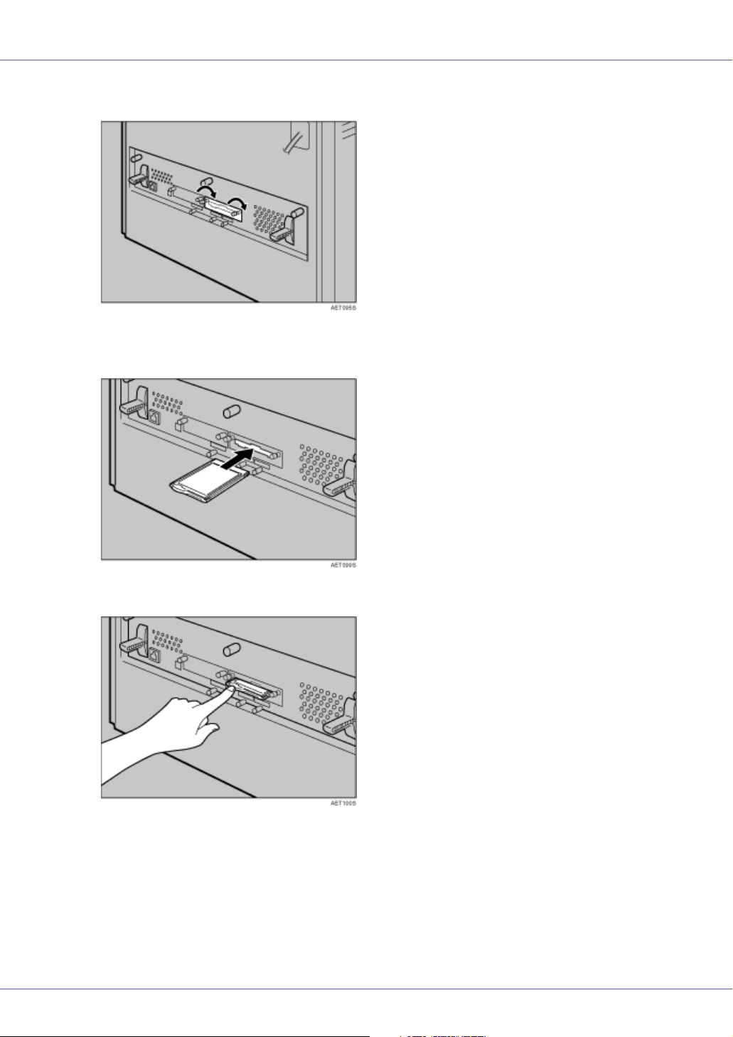
C Remove the cover the controller board's central expansion card slot.
80
Page 81

Installing Options
D Carefully insert the network data protection unit, until the card clicks
into the place.
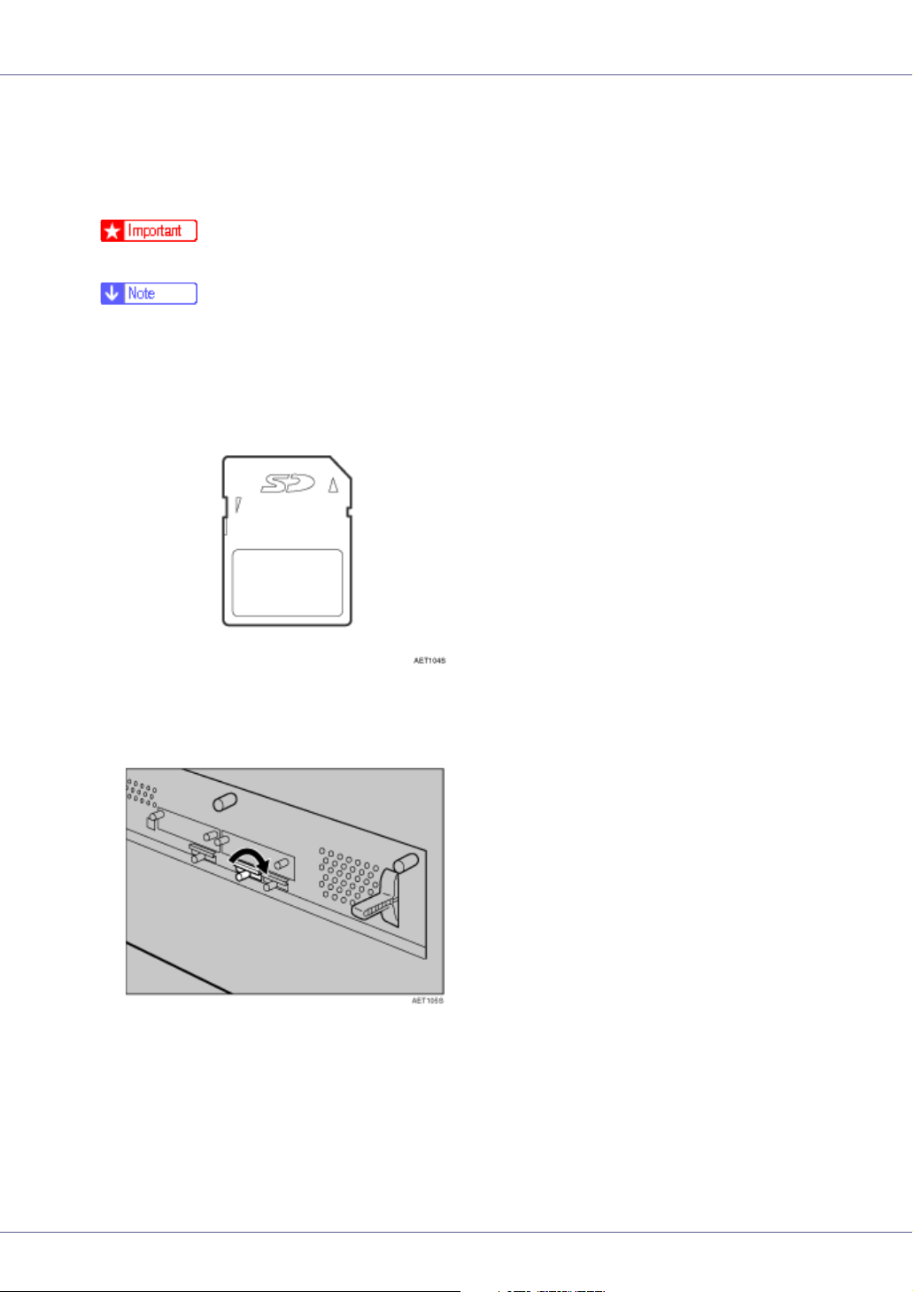
E Reattach the cover over the network data protection unit. Fasten the
screw to secure the cover.
❒ Do not touch the network data protection unit while the machine is in use.
It may come loose, even if pushed only slightly.
81
Page 82

Connecting the Printer
Network Connection
Follow the procedure below to connect the printer to the computer through the
network. Prepare the hub and other network devices before connecting the 10
BASE-T or 100 BASE-TX cable to the machine's Ethernet port.
❒ Use shielded Ethernet cable. Unshielded cables create electromagnetic inter-
ference that could cause malfunctions.
❒ Ethernet cable is not supplied with this machine. Select your cable according
to the network environment.
A Attach one ferrite core at the printer end of the Ethernet cable, and then
attach the other ferrite core about 10 cm (4 inches) ( ) from this core.
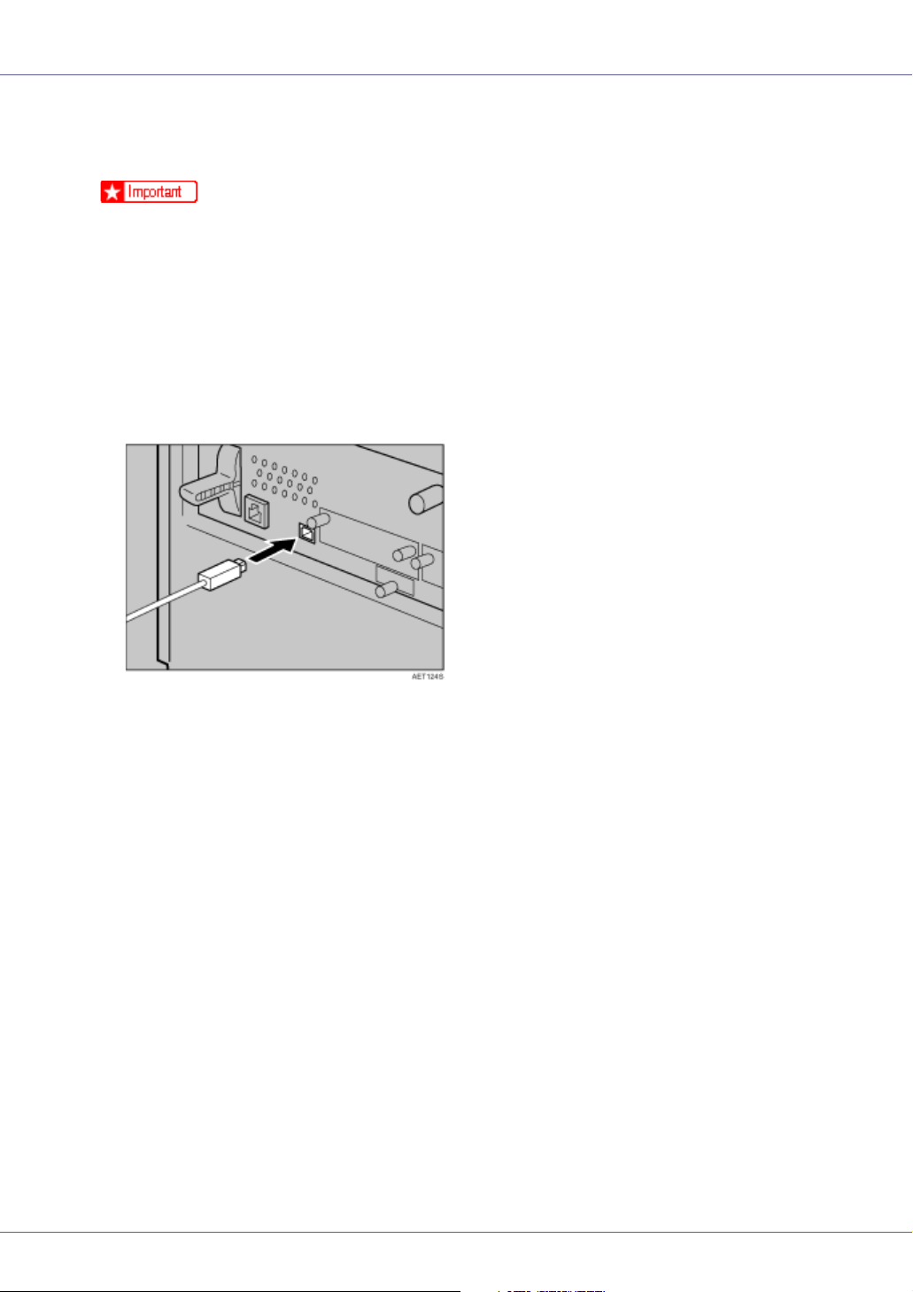
B Connect the Ethernet cable to the Ethernet port.
C Connect the other end of the cable to the printer's network, such as a
hub.
For details about network environment settings, see Software Guide.
G1058604A_1.10 Copyright © 2004, 2005 82
Page 83

Connecting the Printer
- Reading the LED Lamps
1. Yellow: lit when 100BASE-TX is being used. Unlit when 10BASE-T is be-
ing used.
2. Green: lit when the printer is properly connected to the network.
83
Page 84
Connecting the Printer
USB Connection
❒ USB2.0 interface cable is not supplied. Obtain it separately, according to the
computer you are using.
❒ USB connection is possible under Windows 98 SE/Me/2000/XP, Windows
Server 2003, Mac OS 9.x, and Mac OS X.
❒ Windows 98SE/Me supports USB1.1 speeds.
❒ USB connection with Macintosh is only possible via the printer's USB port.
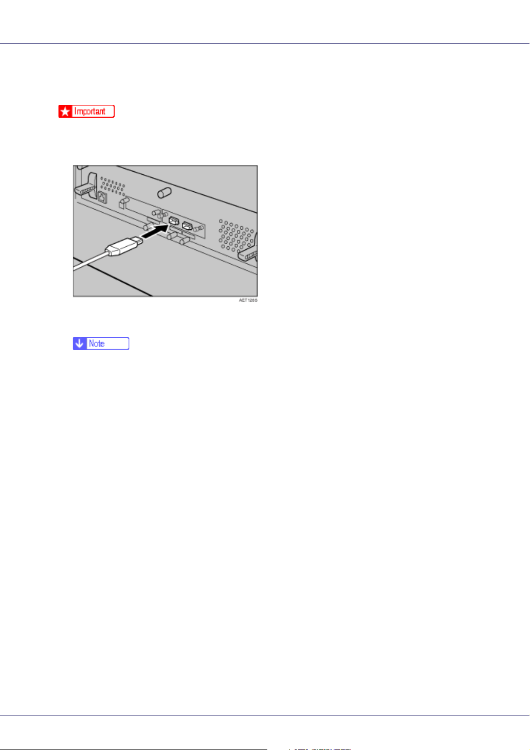
A Connect the square-shaped connector of the USB2.0 cable to the USB
port.
B Connect the opposite end's flat connector to devices such as your com-
puter's USB interface, or a USB hub.
84
Page 85

Connecting the Printer
Parallel Connection
❒ The parallel interface cable is not provided with the printer.
❒ The printer's parallel connection is a standard bidirectional interface that re-
quires an IEEE 1284-compliant 36-pin parallel cable and host computer parallel port.
❒ Use shielded interface cable. Unshielded cables create electromagnetic inter-
ference that could cause malfunctions.
A Turn off the printer and computer.
B Connect the cable to the interface socket of the IEEE 1284 interface
board.
❒ Voltage rating of the computer's parallel port: DC 5 V (max.)
C Securely attach the other end of the parallel cable to your computer's
parallel port. Secure the cable.
For details about settings for parallel connection printing, see Software
Guide.
85
Page 86
Connecting the Printer
IEEE 1394 Connection
❒ Use the 1394 interface cable provided with the 1394 interface board.
A Connect the interface cable to the 1394 interface board.
B Connect the other end to the host computer.
❒ You can use either connector.
❒ If you have an interface cable with a ferrite core, connect the ferrite core
end to the printer.
86
Page 87

Configuration
Ethernet Configuration
Make the following network settings according to the network interface you are
using.
You can use SmartDeviceMonitor for Admin or a Web browser to make IP address-related settings in a TCP/IP-capable environment.
❒ Configure the printer for the network using the control panel.
❒ The following table shows the control panel settings and their default values.
These items appear in the “Host Interface” menu.
Setting Name Value
DHCP On
IP Address 011.022.033.044
Subnet Mask 000.000.000.000
Gateway Address 000.000.000.000
Frame Type (NW) Auto
Active Protocol TCP/IP Active
NetWare Active
SMB Active
AppleTalk
Ethernet Speed Auto
LAN Type Ethernet
Active
❒ If DHCP is in use, the IP address, subnet mask, and gateway address are all
set automatically.
❒ Make this setting only when it is necessary. See Software Guide.
A Press the {Menu} key.
G1058604A_1.10 Copyright © 2004, 2005 87
Page 88

Configuration
“Menu” appears on the display.
B Press the {U} or {T} key to display “Host Interface” menu, and then
press the {# Enter} key.
Menu:
Host Interface
The interface setting menu appears.
C Press the {U} or {T} key to display “Network Setup”, and then press the
{# Enter} key.
The network setup menu appears.
D Press the {U} or {T} key to display “Active Protocol”, and then press
the {# Enter} key.
E Press the {U} or {T} key to select Active Protocol, and then press the
{# Enter} key.
Active Protocol:
TCP/IP
The following example explains activating TCP/IP.
The “Active/Not Active” selection screen appears.
F Press the {U} or {T} key to select “Active” or “Not Active”, and then
press the {# Enter} key.
TCP/IP:
*Active
After the settings are made, about two seconds later, the screen returns to the
active protocol menu.
G Set other protocols you need to set in the same way.
H Press the {Escape} key, the screen returns to the network setup menu.
❒ The default is “Active”.
❒ Leave unused protocols “Not Active”.
❒ Enable TCP/IP to use the Pure IP environment of NetWare 5/5.1, NetWare
6/6.5.
I If you use TCP/IP, assign the IP address to the printer. Press the {U} or
{T} key to display “IP Address”, and then press the {# Enter} key.
The current IP address appears on the display.
88
Page 89

Configuration
To get the IP address for the printer, contact your network administrator.
J Press the {U} or {T} key to enter the left most entry field of the IP ad-
dress, and then press the {# Enter} key.
IP Address:
192.022.033.044
Press the {# Enter} key, the screen changes, and the next field can then be
entered.
❒ Do not set “011.022.033.044” as the IP address.
❒ The value moves by 10 if the {U} or {T} key is kept pressed.
❒ When the {# Enter} key is pressed, the cursor moves to the next field.
❒ To display the previous field, press the {Escape} key.
❒ Press the {Escape} key when no value is entered and the screen will return
to the network setup menu, without the IP address changing.
K Make the other settings in the same way, and then press the {# Enter}
key.
IP Address:
192.168.000.010
After the settings are made, about two seconds later, the screen returns to the
network setup menu.
L If you use TCP/IP, assign “Subnet Mask” and “Gateway Address” fol-
lowing the same procedure for entering the IP address.
M When you use this machine in DHCP environment, set DHCP to “On”.
❒ When DHCP is “On”, you cannot make settings for the following items:
• IP Address
• Subnet Mask
• Gateway Address
❒ Consult your network administrator for information about making network
settings.
89
Page 90

Configuration
N Press the {U} or {T} key to display “DHCP”, and then press the {# Enter}
key.
Network Setup:
DHCP
O Press the {U} or {T} key to display “On”, and then press the {# Enter}
key.
DHCP:
*On
❒ “p” shows the current setting.
❒ After about two seconds, the display returns to the network setup menu.
P If you use NetWare, select the frame type for NetWare.
Select one of the items below if necessary.
• Auto (Default)
• Ethernet II
• Ethernet 802.2
• Ethernet 802.3
• Ethernet SNAP
❒ Usually, use the default setting (“Auto”). When you first select “Auto”, the
frame type detected by the printer is adopted. If your network can use more
than two frame types, the printer may fail to select the correct frame type if
“Auto” is selected. In this case, select the appropriate frame type.
Q Press the {U} or {T} key to display “Frame Type (NW)”, and then press
the {# Enter} key.
Network Setup:
Frame Type (NW)
The current setting appears on the display.
R Press the {U} or {T} key to display the frame type you want to use, and
then press the {# Enter} key.
Frame Type (NW):
*Auto Select
90
Page 91

Configuration
After the settings are made, about two seconds later, the screen returns to the
network setup menu.
S Press the {Online} key.
“Ready” appears on the display.
T Print a configuration page to confirm the settings made.
For details about printing the configuration page, see p.39 “Test Printing”.
91
Page 92
Configuration
IEEE 802.11b (Wireless LAN) Configuration
Configure the printer to use IEEE 802.11b (Wireless LAN). The following table
shows the control panel settings and their default values. These items appear in
the “Host Interface” menu.
Setting Name Default Value
Comm. Mode 802.11 Ad hoc
Channel • Inch version
(1-11) 11
• Metric version
(1-13) 13
Trans. Speed Auto
SSID blank (ASSID)
WEP Setting Not Active
❒ To use IEEE 802.11b (Wireless LAN), select “IEEE 802.11b” for “LAN Type”
in “Network Setup” in the “Host Interface” menu, and then set “IP Address”,
“Subnet Mask”, “Gateway Address”, “DHCP”, “Frame Type (NW)” and “Active
Protocol” under “Network Setup”. For details about setting items under “Configuring the Printer for the Network”, see Software Guide.
❒ The 802.11b interface unit cannot be used simultaneously with a standard
ethernet interface.
❒ In the “SSID” menu, if blank is specified in 802.11b Ad hoc mode or Ad hoc
mode, “ASSID” appears.
A Press the {Menu} key.
“Menu” appears on the display.
92
Page 93
Configuration
B Press the {U} or {T} key to display “Host Interface” menu, and then
press the {# Enter} key.
Menu:
Host Interface
The interface setting menu appears.
C Press the {U} or {T} key to display “IEEE 802.11b” , and then press the
{# Enter} key.
The IEEE 802.11b setting menu appears.
D Press the {U} or {T} key to display “Comm. Mode” , and then press the
{# Enter} key.
E Press the {U} or {T} key to select the transmission mode of IEEE
802.11b, and then press the {# Enter} key.
Comm. Mode:
*802.11 Ad hoc
After the settings are made, about two seconds later, the screen returns to the
IEEE 802.11b setting menu.
❒ The factory default is “802.11 Ad hoc”.
❒ To use an IEEE 802.11b card for which the SSID (Network Name) setting
is not necessary, select “Ad hoc”.
❒ The transmission mode of IEEE 802.11b can also be set using a Web
browser. For details, see Web browser, and “Configuring the Network Interface Board Using Web Browser”, Software Guide.
F If “802.11 Ad hoc” or “Ad hoc” is selected for “Comm. Mode”, set the
channel to use for transmission.
❒ Confirm the network administrator for the channel to use.
G Press the {U} or {T} key to display “Channel”, and then press the {# En-
ter} key.
The channel currently used appears on the display.
H Press the {U} or {T} key to enter the channel, and then press the {# En-
ter} key.
Channel:
(1-13) 13
93
Page 94

Configuration
I Set “Trans. Speed” in the same way.
❒ The factory default is “Auto”. If you need to change the transmitting speed
depending on environment you are using, select the appropriate transmitting speed.
J If “Infrastructure” or “802.11 Ad hoc” is selected for “Comm. Mode”, set
SSID to use for transmission.
❒ Confirm the network administrator for SSID to use.
❒ SSID can also be set using a Web browser. For details, see the Web Image
Monitor Help, and “Configuring the Network Interface Board Using Web
Browser”, Software Guide.
K Press the {U} or {T} key to display “SSID”, and then press the {# Enter}
key.
The following message appears on the display.
SSID:
View
If an SSID has been set, you can check the set SSID. Press the {# Enter} key.
L Press the {U} or {T} key to display “Enter ID”, and then press the {# En-
ter} key.
The following message appears on the display.
SSID: [ 0]
k
The value in brackets at the upper right is the number of characters entered.
M Press the {U} or {T} key to select characters, and then press the {# En-
ter} key.
SSID: [ 1]
Ak
You can now enter the next character.
N Continue entering the key.
❒ The characters that can be used are ASCII 0x20-0x7e (32 bytes).
❒ To display the previous character, press the {Escape} key.
94
Page 95

Configuration
O After entering the key, press the {# Enter} key twice.
SSID: [32]
AAAAAAAAAAAAAAAA
After the settings are made, about two seconds later, the screen returns to the
IEEE 802.11b setting menu.
P In the case of using a WEP key on a network, activate the WEP setting
to be used for communication along with WEP.
❒ Confirm the network administrator for the WEP Key to use.
❒ WEP key can also be set using a Web browser. For details, see Web Im-
age Monitor Help.
Q Press the {U} or {T} key to display “WEP Setting”, and then press the
{# Enter} key.
The following message appears on the display.
WEP Setting:
*Not Active
R Press the {U} or {T} key to display “Active”, and then press the {# Enter}
key.
The following message appears on the display.
Change WEP Key:
Yes (HEX)
❒ When setting the WEP Setting to “Active”, you will need to enter the WEP
key. If you have not entered the key, be sure to enter it.
❒ If you have entered the WEP key and change the setting, press the {U} or
{T} key to display “No”, and then press the {# Enter} key.
S Press the {U} or {T} key to display “Yes (HEX)” when inputting a hexa-
decimal WEP key or “Yes (ASCII)” when inputting an ASCII WEP key.
Then press the {# Enter} key.
WEP Key: [ 0]
k
The value in brackets at the upper right is the number of characters entered.
95
Page 96
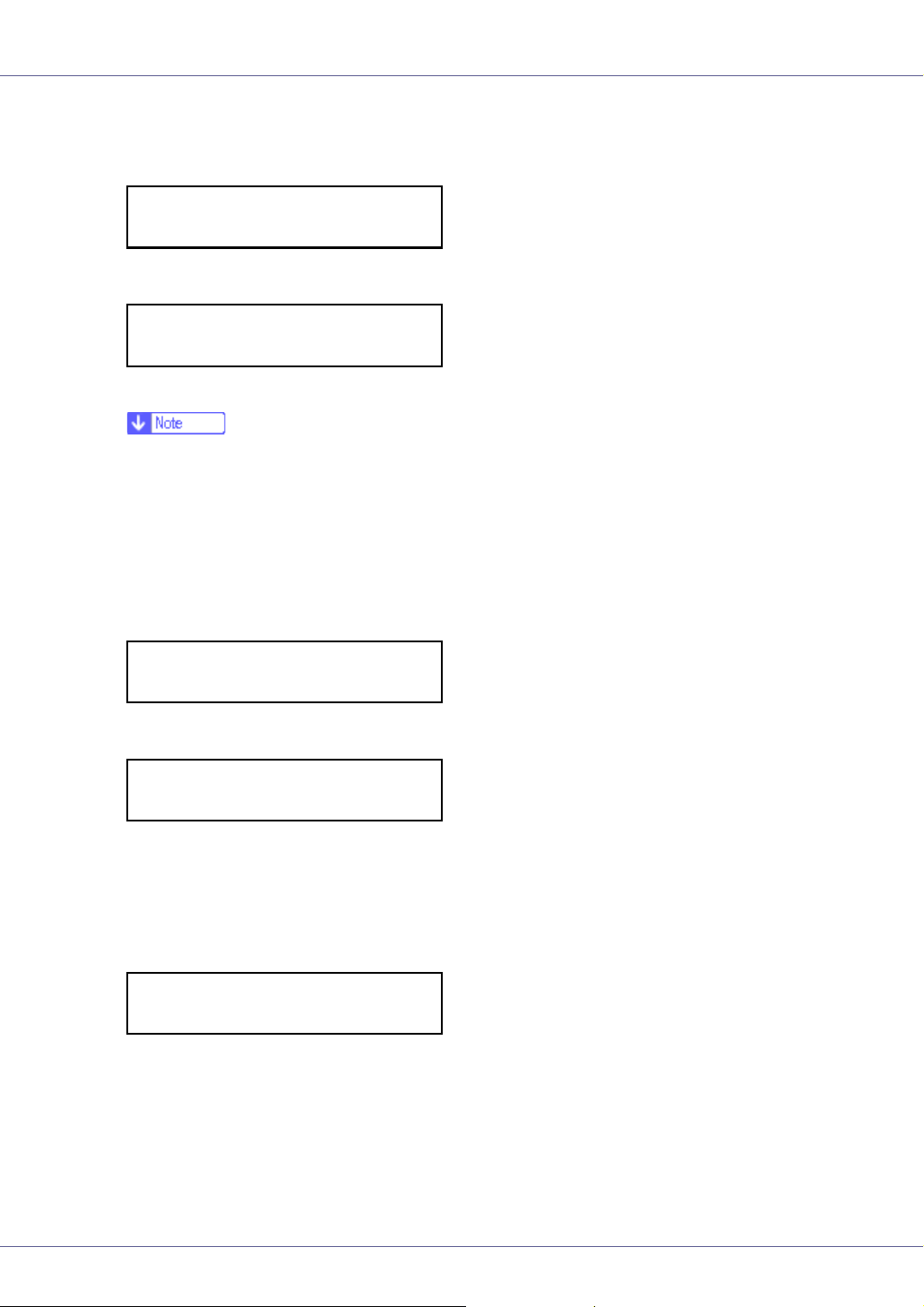
Configuration
T Press the {U} or {T} key to select characters, and then press the {# En-
ter} key.
WEP Key: [ 1]
*k
You can now enter the next character.
WEP Key: [ 2]
**k
Continue entering the key.
❒ When using 64 bit WEP, up to 10 characters can be used for hexadecimal
and up to five characters for ASCII. When using 128 bit WEP, up to 26
characters can be used for hexadecimal and up to 13 characters for ASCII.
❒ The number of characters that can be entered is limited to 10 or 26 for hex-
adecimal and 5 or 13 for ASCII. If you try to enter too many characters, the
following message appears:
• hexadecimal
Error: Enter 10
or 26 characters
• ASCII
Error: Enter 5
or 13 characters
❒ For ASCII character strings, each capital letter and lowercase letter is rec-
ognized respectively.
❒ To display the previous character, press the {Escape} key.
U After entering the key, press the {# Enter} key.
WEP Key: [26]
***************A
After the settings are made, about two seconds later, the screen returns to the
IEEE 802.11b setting menu.
V Press the {Online} key.
“Ready” appears on the display.
W Print a configuration page to confirm the settings made.
96
Page 97

Configuration
For details about printing the configuration page, see p.39 “Test Printing”.
97
Page 98

Configuration
IEEE 1394 Configuration
Use this procedure to configure the printer for use in an IEEE 1394 environment.
The following table shows the control panel settings and their default values.
These items appear in the “Host Interface” menu.
Setting Name Value
DHCP On
IP Address1394 011.022.033.044
Subnet Mask1394 000.000.000.000
IP over 1394 Active
SCSI print Active
Bidi-SCSI print Active
❒ If DHCP is in use, “IP Address1394” and “Subnet Mask1394” are automatical-
ly set.
IP over 1394
A Press the {Menu} key.
“Menu” appears on the display.
B Press the {U} or {T} key to display “Host Interface” menu, and then
press the {# Enter} key.
Menu:
Host Interface
The interface setting menu appears.
C Press the {U} or {T} key to display “IEEE 1394 Setup”, and then press
the {# Enter} key.
98
Page 99
Configuration
The IEEE 1394 setting menu appears.
D Press the {U} or {T} key to display “IP over 1394”, and then press the
{# Enter} key.
The IP over 1394 setting menu appears.
E Press the {U} or {T} key to select either “Active” or “Not Active”, and
then press the {# Enter} key.
IP over 1394:
*Active
After the settings are made, about two seconds later, the screen returns to the
IEEE 1394 setting menu.
F Assign the IP address to the printer. Press the {U} or {T} key to display
“IP Address1394”, and then press the {# Enter} key.
The current IP address appears on the display.
❒ Do not set the same IP address as that used for the Ethernet network set-
tings or in the same subnet. Also, do not specify the same subnet mask.
❒ Do not set “011.022.033.044” as the IP address.
❒ To get the IP address for the printer, contact your network administrator.
G Press the {U} or {T} key to enter the left most entry field of the IP ad-
dress, and then press the {# Enter} key.
IP Address1394:
19k.022.033.044
The pointer (k) moves to the next entry field automatically.
IP Address1394:
192.02k.033.044
❒ The value moves by 10 if the {U} or {T} key is kept pressed.
❒ You can return the pointer (k) to the previous (left) entry field by pressing
the {Escape} key.
❒ If you press the {Escape} key when the pointer (k) is on the leftmost posi-
tion, the selected IP address is reset.
H Set other fields similarly, and then press the {# Enter} key.
The settings are made and after about two seconds, the screen returns to the
IEEE 1394 setting menu.
99
Page 100

Configuration
I Set “Subnet Mask1394” in the same way.
J Press the {Online} key.
“Ready” appears on the display.
K Print a configuration page to confirm the settings made.
For printing the configuration page, see “Printing a Configuration Page”,
Software Guide.
SCSI print
A Press the {Menu} key.
“Menu” appears on the display.
B Press the {U} or {T} key to display “Host Interface” menu, and then
press the {# Enter} key.
Menu:
Host Interface
The interface setting menu appears.
C Press the {U} or {T} key to display “IEEE 1394 Setup”, and then press
the {# Enter} key.
The IEEE 1394 setting menu appears.
D Set “SCSI print” and “Bidi-SCSI print” if necessary.
❒ The default setting is “Active”.
E Press the {U} or {T} key to display “SCSI print”, and the press the {#
Enter} key.
100
 Loading...