

Page 1
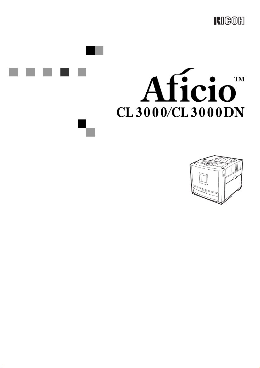
Option Setup Guide
For safety, please read this manual carefully before you use this product and keep it handy
for future reference.
Page 2

ZPIntroduction
To get maximum versatility from this machine all operators should carefully read and follow the instructions in this manual. Please keep this manual in a handy place near the machine.
Please read the Safety Information before using this machine. It contains important information related
to USER SAFETY and PREVENTING EQUIPMENT PROBLEMS.
Important
Contents of this manual are subject to change without prior notice. In no event will the company be liable for direct, indirect, special, incidental, or consequential damages as a result of handling or operating the machine.
Caution:
Use of controls or adjustment or performance of procedures other than those specified in this manual
might result in hazardous radiation exposure.
Do not attempt any maintenance or troubleshooting other than that mentioned in this manual. This
printer contains a laser beam generator and direct exposure to laser beams can cause permanent eye
damage.
Notes:
Some illustrations in this manual might be slightly different from the machine.
Certain options might not be available in some countries. For details, please contact your local dealer.
Two kinds of size notation are employed in this manual. With this machine refer to the metric version.
For good copy quality, supplier recommends that you use genuine supplier's toner.
Supplier shall not be responsible for any damage or expense that might result from the use of parts
other than genuine supplier's office product.
Trademarks
Microsoft, Windows and Windows NT are registered trademarks of Microsoft Corporation in the United
States and/or other countries.
IPS-PRINT Printer Language Emulation Copyright© 1999-2000 Oak Technology, Inc., All rights reserved.
Other product names used herein are for identification purposes only and might be trademarks of their
respective companies. We disclaim any and all rights in those marks.
The proper names of the Windows operating systems are as follows:
• The product name of Windows
• The product name of Windows
• The product name of Windows
• The product names of Windows
• The product names of Windows
• The product names of Windows NT
Microsoft
Microsoft
Microsoft
Microsoft
Microsoft
Microsoft
Microsoft
®
Windows® 2000 Advanced Server
®
Windows® 2000 Server
®
Windows® 2000 Professional
®
Windows® XP Professional
®
Windows® XP Home Edition
®
Windows NT® Server 4.0
®
Windows NT® Workstation 4.0
®
95 is Microsoft® Windows® 95.
®
98 is Microsoft® Windows® 98.
®
Me is Microsoft® Windows® Millennium Edition (Windows Me).
®
2000 are as follows:
®
XP are as follows:
®
4.0 are as follows:
Page 3

TABLE OF CONTENTS
How to Read This Manual .....................................................................................1
1. Options
Available Options...................................................................................................3
PAPER FEED UNIT Type 3000 ..............................................................................8
AD440 (Duplex Unit) ............................................................................................ 11
Memory Unit Type C (SDRAM Module) ..............................................................13
Printer Hard Disk Type 3000 ............................................................................... 16
Formatting the Printer Hard Disk drive.....................................................................18
1394 Interface Unit Type 4510............................................................................. 19
Connecting the cable to the 1394 Interface Unit......................................................22
IEEE 1394 Configuration..........................................................................................22
802.11b Interface Unit Type A .............................................................................25
IEEE 802.11b (Wireless LAN) Configuration ...........................................................28
Bluetooth Interface Unit Type A .........................................................................32
Network Interface Board Type 3000...................................................................35
Connecting the Network Interface Cable to the Network .........................................37
User Account Enhance Unit Type B...................................................................38
INDEX......................................................................................................... 41
i
Page 4

ii
Page 5
How to Read This Manual
R
R
Symbols
In this manual, the following symbols are used:
WARNING:
This symbol indicates a potentially hazardous situation which, if instructions
are not followed, could result in death or serious injury.
CAUTION:
This symbol indicates a potentially hazardous situation which, if instructions
are not followed, may result in minor or moderate injury or damage to property.
* The statements above are notes for your safety.
Important
If this instruction is not followed, paper might be misfed, or data might be lost.
Be sure to read this.
Preparation
This symbol indicates the prior knowledge or preparations required before operating.
Note
This symbol indicates precautions for operation, or actions to take after misoperation.
Limitation
This symbol indicates numerical limits, functions that cannot be used together,
or conditions in which a particular function cannot be used.
Reference
This symbol indicates a reference.
[]
Keys that appear on the machine's panel display.
Keys and buttons that appear on the computer's display.
{}
Keys built into the machine's control panel.
Keys on the computer's keyboard.
1
Page 6

2
Page 7
1. Options
R
Available Options
CAUTION:
• Before installing options, the machine should be turned off and unplugged
for at least an hour. Components inside the machine become very hot, and
can cause a burn if touched.
• Before moving the machine, unplug the power cable from the outlet. If the
cable is unplugged abruptly, it could become damaged. Damaged plugs or
cables can cause an electrical or fire hazard.
• When lifting the machine, use the grips on both sides. The machine could
break or cause an injury if dropped.
By installing options, you can improve the printer performance and have an expanded variety of features to use. For the specifications of each option, see the
Administrator Reference.
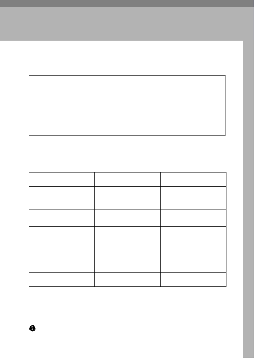
❖❖❖❖ Option List
Basic model Printer Network standard model
PAPER FEED UNIT Type
3000
AD440 (Duplex Unit)
Memory Unit Type C
Printer Hard Disk Type 3000
1394 Interface Unit Type 4510
802.11b Interface Unit Type A
Bluetooth Interface Unit Type
A
Network Interface Board
Type 3000
User Account Enhance Unit
Type B
❍: Available option
*1
With Basic model, these cannot be installed at the same time
*2
With Network standard model, these cannot be attached at the same time.
❍❍
❍
❍❍
❍❍
*1
❍
*1
❍
*1
❍
*1
❍
❍❍
Printer
*2
❍
*2
❍
*2
❍
When installing multiple options on the printer, we recommend the following
order of installation.
Important
❒ The voltage rating of the connector for options is 24V DC or less.
3
Page 8
Options
❖❖❖❖ Option Installation Flow Chart
A
Attach the Paper Feed Unit.
1
(PAPER FEED UNIT Type 3000)
T
B
Install the Duplex Unit.
(AD440)
T
C
Install the SDRAM Module.
(Memory Unit Type C)
T
D
Install the Printer Hard Disk.
(Printer Hard Disk Type 3000)
T
E
Install the 1394 Interface Unit.
(1394 Interface Unit Type 4510)
T
F
Install the 802.11b Interface Unit
(802.11b Interface Unit Type A)
T
G
Install the Bluetooth Interface
Unit
(Bluetooth Interface Unit Type
A)
T
H
Install the Network Interface
Board
(Network Interface Board Type
3000)
T
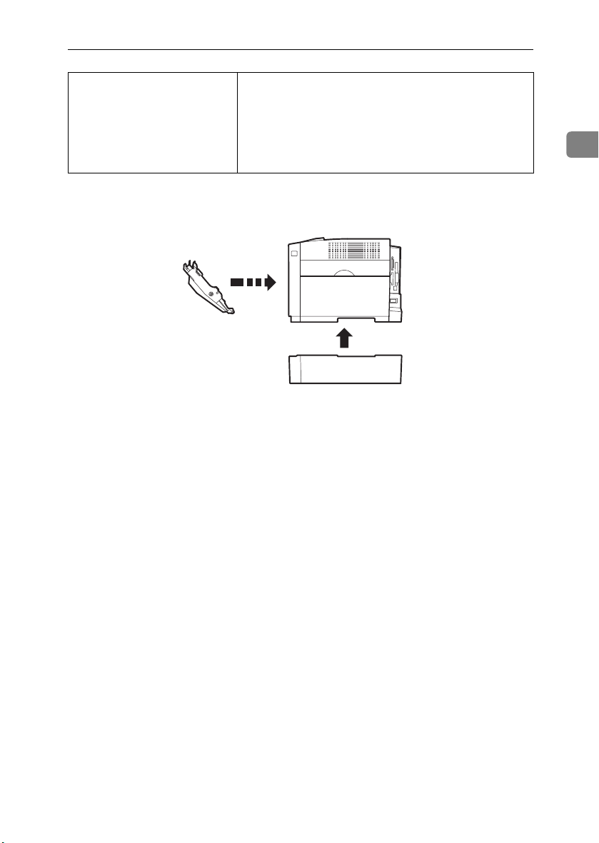
Attach the Paper Feed Unit to the bottom of the printer.
You can attach up to two Paper Feed Units.
Install the unit to the back of the front cover.
Install the module to the SDRAM module slot on the controller board.
64MB, 128MB, and 256MB Memory Units are available.
Install the Printer Hard Disk to the controller board.
Install the 1394 Interface Unit to the slot on the controller
board.
If you choose to install the 1394 Interface Unit, remove the
USB2.0 Interface Board and you cannot install the 802.11b
Interface Unit or Bluetooth Interface Unit.
Install the 802.11b Interface Unit to the slot on the controller
board.
If you choose to install the 802.11b Interface Unit, remove
the USB2.0 Interface Board and you cannot install the 1394
Interface Unit or Bluetooth Interface Unit.
Install the Bluetooth Interface Unit to the slot on the controller board.
If you choose to install the Bluetooth, remove the USB2.0 Interface Board and you cannot install the 802.11b Interface
Unit or 1394 Interface Unit.
Install the Network Interface Board to the slot on the controller board, only for basic model printer.
If you choose to install the Network Interface Board, you
cannot install the 1394 Interface Unit, 802.11b Interface Unit
or Bluetooth Interface Unit.
4
Page 9
Available Options
I
Install the User Account Enhance
Unit.
(User Account Enhance Unit
Type B)
T
Install the module to the User Account Enhance Unit slot on
the controller board.
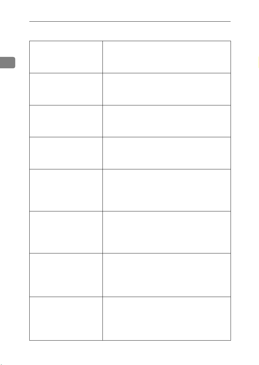
Install options in the positions as shown in the illustration.
❖❖❖❖ Exterior
1
2
1.
AD440 (Duplex Unit)
Install to the back of the front cover.
Makes duplex prints.
See p.11 “AD440 (Duplex Unit)”.
2.
PAPER FEED UNIT Type 3000
Loads up to 530 sheets of paper. Up to
two units can be attached to the printer. "Tray 2" appears on the panel display for the first unit and "Tray 3"
appears on the panel display for the
second unit.
See p.8 “PAPER FEED UNIT Type
3000”
1
ZHBH050E
5
Page 10
Options
❖❖❖❖ Basic model Printer : Interior
1
2
1
3
4
7
5
6
ZHBHA061E
1.
Printer Hard Disk Type 3000
Install Printer Hard Disk to the controller board.
See p.16 “Printer Hard Disk Type
3000”.
2.
User Account Enhance Unit Type
B
See p.38 “User Account Enhance Unit
Type B”.
3.
802.11b Interface Unit Type A
Note
❒ 802.11b Interface Unit, USB2.0 In-
terface Board, Bluetooth Interface
Unit and 1394 Interface Unit cannot be installed in the printer at the
same time.
See p.25 “802.11b Interface Unit Type
A”.
4.
Bluetooth Interface Unit
Note
❒ Bluetooth Interface Unit, USB2.0
Interface Board, 802.11b Interface
Unit and 1394 Interface Unit can-
not be installed in the printer at the
same time.
5.
1394 Interface Unit Type 4510
Note
❒ 1394 Interface Unit, USB2.0 Inter-
face Board, Bluetooth Interface
Unit and 802.11b Interface Unit
cannot be installed in the printer at
the same time.
See p.19 “1394 Interface Unit Type
4510”.
6.
Netwok Interface Board Type
3000
Note
❒ Netwok Interface Board, USB2.0
Interface Board, 802.11b Interface
Unit, Bluetooth Interface Unit and
1394 Interface Unit cannot be in-
stalled in the printer at the same
time.
7.
Memory Unit Type C (SDRAM
Module)
Install 64MB, 128MB, or 256MB RAM
into the slot on the controller board.
See p.13 “Memory Unit Type C
(SDRAM Module)”.
Important
❒ Remove USB2.0 Interface Board
when you install 1394 Interface
Unit, 802.11b Interface Unit,
Bluetooth Interface Unit or Net-
wok Interface Board.
6
Page 11
❖❖❖❖ Network standard model Printer : Interior
6
Available Options
1
2
1
3
4
5
ZHBHA062E
1.
Printer Hard Disk Type 3000
Install Printer Hard Disk to the controller board.
See p.16 “Printer Hard Disk Type
3000”.
2.
User Account Enhance Unit Type
B
See p.38 “User Account Enhance Unit
Type B”.
3.
802.11b Interface Unit Type A
Note
❒ 802.11b Interface Unit, USB2.0 In-
terface Board, Bluetooth Interface
Unit and 1394 Interface Unit cannot be installed in the printer at the
same time.
See p.25 “802.11b Interface Unit Type
A”.
4.
Bluetooth Interface Unit
Note
❒ Bluetooth Interface Unit, USB2.0
Interface Board, 802.11b Interface
Unit and 1394 Interface Unit can-
not be installed in the printer at the
same time.
5.
1394 Interface Unit Type 4510
Note
❒ 1394 Interface Unit, USB2.0 Inter-
face Board, Bluetooth Interface
Unit and 802.11b Interface Unit
cannot be installed in the printer at
the same time.
See p.19 “1394 Interface Unit Type
4510”.
6.
Memory Unit Type C (SDRAM
Module)
Install 64MB, 128MB, or 256MB RAM
into the slot on the controller board.
See p.13 “Memory Unit Type C
(SDRAM Module)”.
Important
❒ Remove USB2.0 Interface Board
when you install 1394 Interface
Unit, 802.11b Interface Unit,
Bluetooth Interface Unit.
7
Page 12
Options
R
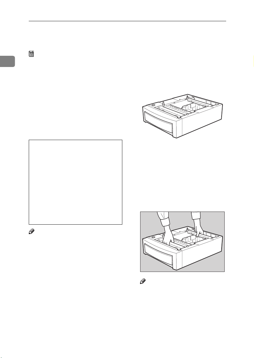
PAPER FEED UNIT Type 3000
Preparation
1
When installing multiple options,
install the Paper Feed Unit first.
Up to two Paper Feed Units can be
attached to the printer. When installing two Paper Feed Units, connect the two units first by
following the procedure below before connecting the units to the
printer. Then, place the printer on
the connected two Paper Feed
Units.
CAUTION:
• When moving the machine, each
person should hold the handles
that are located on opposite
sides, and then lift the machine
slowly. Lifting it carelessly or
dropping it may cause an injury.
• When moving the Paper Feed
Unit, hold the handles that are located on the top of the unit, and
then lift it slowly. Lifting it carelessly or dropping it may cause
an injury.
Check the contents of the package
AAAA
for the following:
❖❖❖❖ Paper Feed Unit (including a paper
tray)
Turn off the power, and then un-
BBBB
plug the power cable.
Hold the Paper Feed Unit as
CCCC
shown in the illustration, and
then place it on a flat surface near
the place where the machine is to
be installed.
ZHBP310E
Note
❒ The printer weighs approximately
29.4 kg (64.8 lb.bond).
❒ The Paper Feed Unit weighs ap-
proximately 7.42 kg (16.4 lb.bond).
❒ "Tray 2" appears on the panel dis-
play when only one unit is installed. "Tray 3" appears on the
panel display for the second unit
when two units are installed.
8
Note
❒ Be sure to work in a place with
enough space, so that you can
get behind the printer.
Page 13
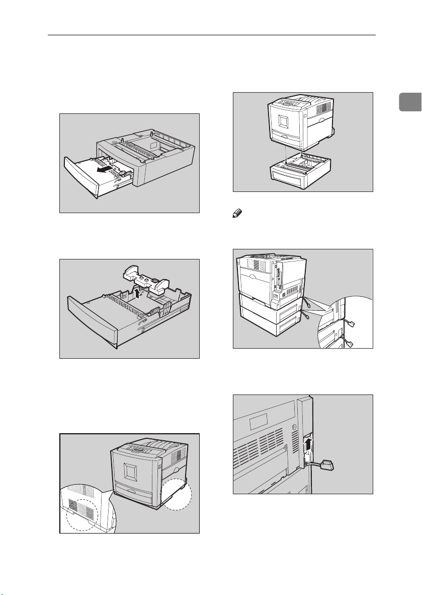
PAPER FEED UNIT Type 3000
Pull the paper tray out of the Pa-
DDDD
per Feed Unit until it stops. After
that, lift it slightly, and then pull
it out completely. Place it on a flat
surface.
Remove the adhesive tape and
EEEE
packing material.
Slide the paper tray completely
FFFF
into the Paper Feed Unit.
ZHBYA930E
ZHBYA950E
Align the printer to the two up-
HHHH
right pins on the Paper Feed Unit
and then lower it slowly.
Note
❒ Be sure not to place the printer
on the Paper Feed Unit cable.
Open the connector cover of the
IIII
printer.
1
ZHBP340E
ZHBP390E
Lift the printer using the inset
GGGG
grips on both sides of the printer.
ZHBP360E
ZHBH750E
9
Page 14
Options
Connect the Paper Feed Unit ca-
JJJJ
ble to the socket inside the printer
securely.
Note
❒ When moving or transporting
the printer, make sure to un-
plug the Paper Feed Unit con-
1
nector. For more information,
see "Moving and Transporting
the Printer" in the Maintenance
Guide.
Note
❒ After finishing installation, you
can check whether the Paper
Feed Unit is installed properly.
ZHBP370E
Print the configuration page
from the "List/Test Print"
Close the connector cover of the
KKKK
printer.
menu. If it is installed properly,
you will see "Paper Feed Unit
(Tray 2)" or "Paper Feed Unit
(Tray 3)" under the "Options"
list.
❒ If the Paper Feed Unit is not in-
stalled properly, reinstall it
from step
. If you cannot in-
C
stall it properly even after at-
tempting reinstallation, contact
your sales or service representa-
ZHBP380E
To connect two Paper Feed Units,
connect the paper feed unit cable
to the socket inside the Paper Feed
Unit securely, and then close the
connector cover.
tive.
Reference
For printing the configuration
page, see "Making Printer Set-
tings with the Control Panel" in
the Administrator Reference.
See "Loading Paper" in the
Maintenance Guide.
10
Important
❒ Before using the new Paper
Feed Unit, you must make set-
tings in the printer driver.
ZHBP390E
Page 15
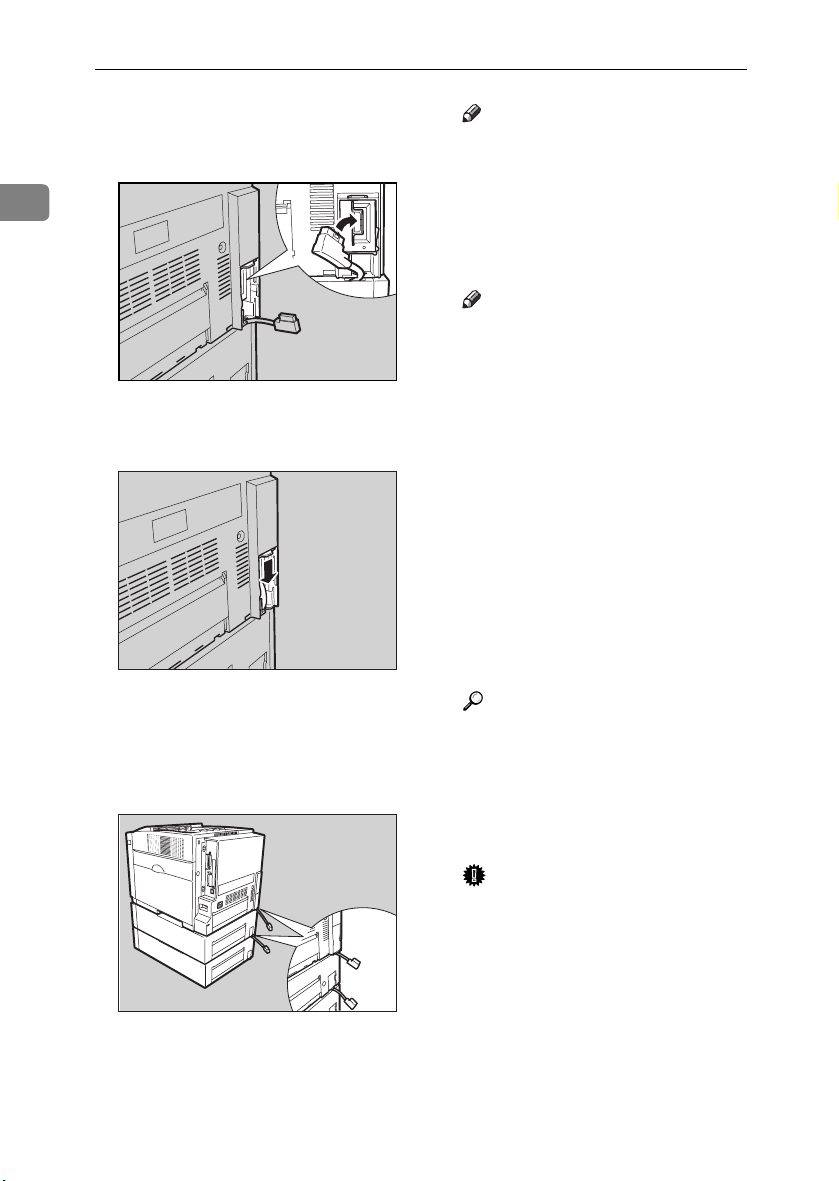
AD440 (Duplex Unit)
R
AD440 (Duplex Unit)
CAUTION:
• The inside of the machine be-
comes very hot. Do not touch the
parts with a "v" label (means
hot surface). Touching a part
with a "v" label (means hot surface) could result in a burn.
Turn off the power, and then un-
AAAA
plug the power cable.
Check the contents of the package
BBBB
for the following:
❖❖❖❖ Duplex Unit
Open the front cover by pushing
CCCC
the front cover release button.
ZHBP240E
Hold the Duplex Unit as shown in
DDDD
the illustration, and then insert it
into the inside of the front cover.
Align the arrows, and then insert
the Duplex Unit until it clicks.
Close the front cover.
EEEE
1
ZHBP270E
ZHBP280E
ZHBP260E
ZHBP282E
11
Page 16

Options
Note
❒ After finishing installation, you
can check whether the Duplex
Unit is installed properly. Print
1
the configuration page from the
"List/Test Print" menu. If it is
installed properly, you will see
"Duplex Unit" under the "Options" list.
❒ If the Duplex Unit is not in-
stalled properly, reinstall it
from step
stall it properly even after attempting reinstallation, contact
your sales or service representative.
Reference
See "Making Printer Settings
with the Control Panel" in the
Administrator Reference for
printing the configuration page.
Important
❒ Before using the Duplex Unit,
you must make settings in the
printer driver.
. If you cannot in-
C
12
Page 17

Memory Unit Type C (SDRAM Module)
R
Memory Unit Type C (SDRAM Module)
CAUTION:
• Do not touch the inside of the
controller board compartment. It
may cause a machine malfunction or a burn.
Important
❒ Before touching the Memory Unit,
touch something metal to discharge any static electricity. Static
electricity can damage the Memory Unit.
❒ Do not subject the Memory Unit to
physical shocks.
Turn off the power, and then un-
AAAA
plug the power cable.
Remove the two screws that fas-
BBBB
ten the controller board on the
back of the printer.
While holding the handle, pull
CCCC
out the controller board slowly.
There are two slots for the Memory
Unit. Use the available slot (the
one in the front in the illustration
B) to install an optional Memory
Unit
1
ZHBP020E
ZHBP080E
The removed screws will be used
in step
board.
to fasten the controller
G
ZHBP100E
Important
❒ In order to install the maximum
384 MB memory, remove the
standard Memory Unit A, and
then replace with the 128 MB
Memory Unit. Then install the
256 MB Memory Unit onto the
other slot (the one in the front in
the illustration B).
❒ When using only one Memory
Unit, be sure to use the slot in
the back shown in the illustra-
tion A.
13
Page 18

Options
Note
❒ The following is the recom-
mended combination of the
Memory Units.
1
CN2 (back
Adjust the notch of the Memory
DDDD
Slot
AAAA
)
64 MB None 64 MB
64 MB 64 MB 128 MB
64 MB 128 MB 192 MB
64 MB 256 MB 320 MB
128 MB 256 MB 384 MB
CN3
(front
Total
memory
BBBB
)
Align the controller board to the
FFFF
top and bottom rails, and then
push in slowly until it stops.
Note
❒ When installing other options
on the controller board, do not
close the controller board, but
go to the steps for installing the
option.
Unit to the slot, and then insert
vertically.
ZHBP070E
Important
❒ The printer may not work prop-
erly if the controller board is not
set properly.
Fasten the controller board to the
GGGG
printer with the two screws that
ZHBP110E
you removed in step
.
BBBB
14
Press the Memory Unit down un-
EEEE
til it clicks into place.
ZHBP010E
ZHBP120E
Page 19

Note
❒ After finishing installation, you
can check whether the Memory
Unit is installed properly. Print
the configuration page from the
"List/Test Print" menu. If it is
installed properly, you will see
the memory capacity for "Total
Memory".
❒ If the Memory Unit is not in-
stalled properly, reinstall it
from step
stall it properly even after attempting reinstallation, contact
your sales or service representative.
Reference
For printing the configuration
page, see "Making Printer Settings with the Control Panel" in
the Administrator Reference.
Important
❒ Before using the new Memory
Unit, you must make settings in
the printer driver.
. If you cannot in-
A
Memory Unit Type C (SDRAM Module)
1
15
Page 20

Options
R
Printer Hard Disk Type 3000
CAUTION:
1
• Do not touch the inside of the
controller board compartment. It
may cause a machine malfunction or a burn.
Important
❒ Before touching the Printer Hard
Disk, touch something metal to
discharge any static electricity.
Static electricity can damage the
Printer Hard Disk.
❒ Do not subject the Printer Hard
Disk to physical shocks.
Check the contents of the package
AAAA
for the following:
❖❖❖❖ Printer Hard Disk Type 3000
ZHBPD010E
Remove the two screws that fas-
CCCC
ten the controller board on the
back of the printer.
The removed screws will be used
in step
board.
While holding the handle, pull
DDDD
out the controller board slowly.
to fasten the controller
H
ZHBP080E
16
❖❖❖❖ Screw
Turn off the power, and then un-
BBBB
plug the power cable.
ZHBP020E
The Printer Hard Disk is to be installed to the position shown in the
illustration.
ZHBP160E
Page 21

Printer Hard Disk Type 3000
Insert the Printer Hard Disk by
EEEE
aligning it with the controller
board slot, sliding it in the direction of the arrow, and then connecting it to the connector on the
controller board.
Fasten the Printer Hard Disk us-
FFFF
ing the supplied screw.
Align the controller board to the
GGGG
top and bottom rails, and then
push in slowly until it stops.
ZHBP170E
ZHBP180E
ZHBP070E
Note
❒ When installing other options
on the controller board, do not
close the controller board, but
go to the steps for installing the
option.
Important
❒ The printer may not work prop-
erly if the controller board is not
set properly.
Fasten the controller board to the
HHHH
printer with the two screws that
you removed in step
When the power is turned on, the
Printer Hard Disk will be formatted automatically.
Note
❒ After finishing installation, you
can check whether the Printer
Hard Disk is installed properly.
Print the configuration page
from the "List/Test Print"
menu. If it is installed properly,
you will see "Printer Hard Disk
Drive" for "Controller Option".
❒ If the Printer Hard Disk is not
installed properly, reinstall it
from step
stall it properly even after at-
tempting reinstallation, contact
your sales or service representa-
tive.
. If you cannot in-
B
.
CCCC
1
ZHBP010E
17
Page 22

Options
Reference
See "Making Printer Settings
with the Control Panel" in the
Administrator Reference for
1
printing the configuration page.
Important
❒ Before using the new Printer
Hard Disk, you must make the
settings in the printer driver.
Formatting the Printer Hard Disk drive
If it becomes necessary to format the
Printer Hard Disk after initial setup,
execute "HDD Format" in the Maintenance menu.
Important
❒ Formatting the Printer Hard Disk
will delete all data.
Press the {{{{Menu}}}} key.
AAAA
"Menu" appears on the panel display.
Press the {{{{UUUU}}}} or {{{{TTTT}}}} key to dis-
BBBB
play "Maintenance", and then
press the {{{{Enter #}}}} key.
Press the {{{{UUUU}}}} or {{{{TTTT}}}} key to dis-
CCCC
play "HDD Format", and then
press the {{{{Enter #}}}} key.
A message to start to format is
shown.
Note
❒ If "HDD Format" is not dis-
played on the panel display, the
Printer Hard Disk is not in-
stalled properly. Reinstall it
from step
stall it properly even after the
reinstallation, contact your sales
or service representative.
Important
❒ Do not turn off the power while
formatting the Printer Hard
Disk to avoid a printer malfunc-
tion.
Press the {{{{Enter #}}}} key.
DDDD
The Printer Hard Disk is formatted, and a message to restart the
printer is shown.
Turn off the power, and then turn
EEEE
it back on.
Formatting the Printer Hard Disk
is completed and it is enabled to
use.
. If you cannot in-
A
Menu:
Maintenance
18
Page 23

1394 Interface Unit Type 4510
R
1394 Interface Unit Type 4510
CAUTION:
• Do not touch the inside of the
controller board compartment. It
may cause a machine malfunction or a burn.
Important
❒ Printing using "1394/Scsi Printer"
(Windows 2000) device and "IEEE
1394 and SCSI printers" (Windows
XP) with the optional 1394 Interface Unit is possible under Windows 2000 and Windows XP.
Printing with IP over 1394 is possible under Windows Me and Windows XP.
❒ Under Windows 2000, the 1394 In-
terface Unit can only be used with
Service Pack 1 or later. If the Service Pack is not installed, the connectable SCSI print device in a
1394 bus is only one. The client
cannot install the printer driver
without using an account with Administrators permission.
❒ Before touching the 1394 Interface
Unit, touch something metal to
discharge any static electricity.
Static electricity can damage the
1394 Interface Unit
❒ Unplug all the interface cables
from the printer before installation. If you take out the controller
board with cables plugged in, the
1394 Interface Unit might be damaged.
❒ Do not plug or unplug the 1394 in-
terface cable while installing the
printer driver
❒ Use the 1394 Interface cable that
comes with 1394 Interface Unit.
Check the contents of the package
AAAA
for the following:
❖❖❖❖ 1394 Interface Unit Type 4510
❖❖❖❖ Interface Cable (6 pins ×××× 6 pins)
❖❖❖❖ Interface Cable (6 pins ×××× 4 pins)
Turn off the power, and then un-
BBBB
plug the power cable and the interface cable.
1
ZHBP400E
19
Page 24

Options
Remove the two screws that fas-
CCCC
ten the controller board on the
back of the printer.
Note
❒ The removed screws will be
used in step
to fasten the 1394
G
Interface Unit.
1
❒ Lift the end of USB2.0 Interface
Unit (A), and then remove it
from the controller board (B).
2
ZHBP080E
1
The removed screws will be used
in step
to fasten the controller
I
board.
ZHBP450E
While holding the handle, pull
DDDD
out the controller board slowly.
Attach the 1394 Interface Unit to
FFFF
the controller board. Insert the
end of the 1394 Interface Unit into
the opening (AAAA), and then push
down until it clicks (BBBB).
20
Remove USB2.0 Interface Unit.
EEEE
ZHBP020E
ZHBPB460E
1
2
ZHBP050E
Confirm that the 1394 Interface
Unit is firmly connected to the controller board.
Page 25

1394 Interface Unit Type 4510
Fasten the 1394 Interface Unit on
GGGG
the controller board using the
screws that you removed in step
.
EEEE
Align the controller board to the
HHHH
top and bottom rails, and then
push in slowly until it stops.
Note
❒ When installing other options
on the controller board, do not
close the controller board, but
go to the steps for installing the
option.
ZHBPB060E
Fasten the controller board to the
IIII
printer with the two screws that
you removed in step
Note
❒ After finishing installation, you
can check whether the 1394 In-
terface Unit is installed proper-
ly. Print the configuration page
from the "List/Test Print"
menu. If it is installed properly,
you will see "IEEE1394" for
"Controller Option".
❒ If the 1394 Interface Unit is not
installed properly, reinstall it
from step
stall it properly even after at-
tempting reinstallation, contact
your sales or service representa-
tive.
. If you cannot in-
B
.
CCCC
1
ZHBP010E
ZHBP070E
Important
❒ The printer may not work prop-
erly if the controller board is not
set correctly.
Reference
See "Making Printer Settings
with the Control Panel" in the
Administrator Reference for
printing the configuration page.
21
Page 26

Options
Connecting the cable to the 1394 Interface Unit
1
Connect the interface cable to the
AAAA
1394 interface port.
Note
❒ Either connector can be used.
❒ If you use a interface cable (6
pins x 6 pins) connect the end
with the ferrite core to the printer.
Connect the other end to the host
BBBB
computer.
Important
❒ You cannot plug devices togeth-
er to create loops.
❒ Do not use a cable more than 4.5
meters (14.8 feet) long.
ZHBP090E
IEEE 1394 Configuration
Use this procedure to configure the
printer for use in the IEEE 1394 environment. The following table shows
the control panel settings and their
default values. These items are included in the "Host Interface" menu.
Setting Name Value
IP Address1394 000.000.000.000
Subnet Mask1394 000.000.000.000
IP over 1394 Active
SCSI print Active
Bidi-SCSI print Active
Depending on the protocol you use,
procedures vary. See the following table.
IP over 1394 Steps A-H and then
SCSI print Steps A-D and then
Press {{{{Menu}}}}.
AAAA
go to steps M to
go to steps I to
N
N
22
“Menu” appears on the panel display.
Press {{{{UUUU}}}} or {{{{TTTT}}}} to display “Host
BBBB
Interface” menu.
Menu:
Host Interface
ZHBS010E
Page 27

1394 Interface Unit Type 4510
Press {{{{Enter #}}}}.
CCCC
The following message appears on
the panel display.
Host Interface:
I/O Buffer
Press {{{{UUUU}}}} or {{{{TTTT}}}} to display “IEEE
DDDD
1394 Setup”.
Host Interface:
IEEE 1394 Setup
Press {{{{Enter #}}}}.
EEEE
The following message appears on
the panel display.
IEEE 1394 Setup:
IP Address1394
Press {{{{UUUU}}}} or {{{{TTTT}}}} to display “IP
FFFF
over 1394”.
IEEE 1394 Setup:
IP over 1394
A Press {{{{Enter #}}}}.
B Press {{{{UUUU}}}} or {{{{TTTT}}}} to select ei-
ther "Active" or "Not Active".
C Press {{{{Enter #}}}}.
The display returns to the previous menu in a few seconds.
ZHBS040E
Assign the IP address to the print-
GGGG
er.
Do not overlap the IP address in
the same subnet or the same IP address in the network setting.
Note
❒ To get the IP address for the
printer, contact your network
administrator.
A Press {{{{UUUU}}}} or {{{{TTTT}}}} until the fol-
lowing message appears.
IEEE 1394 Setup:
IP Address1394
B Press {{{{Enter #}}}}.
The current IP address appears
on the panel display.
IP Address1394:
000.000.000.000
C Press {{{{UUUU}}}} or {{{{TTTT}}}} to enter the
leftmost entry field of the IP
address.
IP Address1394:
192.000.000.000
D Press {{{{Enter #}}}}.
The pointer (k) moves to the
next entry field automatically.
IP Address1394:
192.02k.000.000
Note
❒ The value moves by 10 if {{{{UUUU}}}}
or {{{{TTTT}}}} is kept pressed.
❒ You can return the pointer
(k) to the previous (left) entry
field by pressing {{{{Escape}}}}.
1
23
Page 28

Options
❒ If you press {{{{Escape}}}} when
the pointer (k) is on the leftmost position, the selected IP
address is reset.
1
E Repeat steps CCCC and DDDD to enter
the IP address.
Press {{{{On Line}}}}.
MMMM
“Ready” appears on the panel display.
Ready
IP Address1394:
192.168.000.011
Check if the pointer (k) is at the
rightmost position, and press
{{{{Enter #}}}} to register the IP address you selected.
Print a configuration page to con-
NNNN
firm the settings made. See
"Printing a Configuration Page"
in the Administrator Reference.
IEEE 1394 Setup:
IP Address1394
Set "Subnet Mask1394" in the
HHHH
same way.
Set "SCSI print" and "Bidi-SCSI
IIII
print" if necessary.
Note
❒ The default setting is "Active".
Press {{{{UUUU}}}} or {{{{TTTT}}}} to display "SCSI
JJJJ
print".
24
IEEE 1394 Setup:
SCSI print
Press {{{{Enter #}}}}.
KKKK
The following message appears on
the panel display.
SCSI print:
*Active
Press {{{{UUUU}}}} or {{{{TTTT}}}} to select either
LLLL
"Active" or "Not Active", and then
press {{{{Enter #}}}}.
Set " Bidi-SCSI print " in the same
way.
Page 29

802.11b Interface Unit Type A
R
802.11b Interface Unit Type A
CAUTION:
• Do not touch the inside of the
controller board compartment. It
may cause a machine malfunction or a burn.
Important
❒ Before touching the 802.11b Inter-
face Unit, touch something metal
to discharge any static electricity.
Static electricity can damage the
802.11b Interface Unit
❒ Do not subject the 802.11b Inter-
face Unit to physical shocks.
Check the contents of the package
AAAA
for the following:
❖❖❖❖ 802.11b Interface Unit Type A
• Interface Unit
• Antenna
Turn off the power, and then un-
BBBB
plug the power cable.
Remove the two screws that fas-
CCCC
ten the controller board on the
back of the printer.
1
ZHBP430E
• Card
ZHBP410E
ZHBP420E
ZHBP080E
The removed screws will be used
in step
board.
to fasten the controller
K
25
Page 30

Options
While holding the handle, pull
DDDD
out the controller board slowly.
Attach the 802.11b Interface Unit.
FFFF
Insert the end of the 802.11b Interface Unit to the opening (AAAA), and
then push down until it clicks
1
ZHBP020E
Remove USB2.0 Interface Unit.
EEEE
(BBBB).
1
2
ZHBP190E
Confirm that the 802.11b Interface
Unit is firmly connected to the controller board.
Fasten the 802.11b Interface Unit
GGGG
on the controller board using the
screws that you removed in step
.
EEEE
ZHBPB460E
Note
❒ The removed screws will be
used in step
.
G
❒ Lift the end of USB2.0 Interface
Unit (A), and then remove it
from the controller board (B).
26
ZHBP200E
Attach the antenna to the card
2
HHHH
with the label facing down and
the uneven side of the antenna
1
ZHBP450E
facing up.
Page 31

802.11b Interface Unit Type A
Insert the card slowly into the
IIII
802.11b Interface Unit with the label facing down and the uneven
black antenna surface facing up
until it stops.
Align the controller board to the
JJJJ
top and bottom rails, and then
push in slowly until it stops.
Note
❒ When installing other options
on the controller board, do not
close the controller board, but
go to the steps for installing the
option.
ZHBP210E
Fasten the controller board to the
KKKK
printer with the two screws that
you removed in step
Note
❒ After finishing installation, you
can check whether the 802.11b
Interface Unit is installed prop-
erly. Print the configuration
page from the "List/Test Print"
menu. If it is installed properly,
you will see "IEEE 802.11b" for
"Controller Option".
❒ If the 802.11b Interface Unit is
not installed properly, reinstall
it from step
stall it properly even after at-
tempting reinstallation, contact
your sales or service representa-
tive.
B
.
CCCC
. If you cannot in-
1
ZHBPB230E
ZHBP220E
Important
❒ The printer may not work prop-
erly if the controller board is not
set properly.
Reference
See "Making Printer Settings
with the Control Panel" in the
Administrator Reference for
printing the configuration page.
27
Page 32

Options
Press {{{{UUUU}}}} or {{{{TTTT}}}} to display “Host
IEEE 802.11b (Wireless LAN)
BBBB
Interface” menu.
Configuration
1
Configure the printer for using the
IEEE 802.11b (Wireless LAN). The following table shows the control panel
settings and their default values.
These items are included in the "Host
Interface" menu.
Setting Name Default Value
Comm. Mode 802.11 Ad hoc
Channel • Inch version
Trans. Speed Auto
WEP Setting Not Active
In order to use the IEEE 802.11b
(Wireless LAN), select "IEEE 802.11b"
for "LAN Type" in "Network Setup"
of the Host Interface menu, and then
set "IP Address", "Subnet Mask",
"Gateway Address", "DHCP", "Frame
Type (NW)" and "Active Protocol" in
the "Network Setup". For more information about setting the items in the
"Network Setup", see the Quick Installation Guide.
Press {{{{Menu}}}}.
AAAA
(1-11) 11
• Metric version
(1-13) 11
Menu:
Host Interface
Press {{{{Enter #}}}}.
CCCC
The following message appears on
the panel display.
Host Interface:
I/O Buffer
Press {{{{UUUU}}}} or {{{{TTTT}}}} to display "IEEE
DDDD
802.11b".
Host Interface:
IEEE 802.11b
Press {{{{Enter #}}}}.
EEEE
Be sure that "Comm. Mode" appears on the panel display.
ZHBS040E
28
ZHBS010E
“Menu” appears on the panel display.
IEEE 802.11b:
Comm. Mode
Press {{{{Enter #}}}}.
FFFF
The following message appears on
the panel display.
Comm. Mode:
*802.11 Ad hoc
Page 33

802.11b Interface Unit Type A
Press {{{{UUUU}}}} or {{{{TTTT}}}} to select the
GGGG
transmission mode.
Note
❒ The factory default is “802.11
Ad hoc”.
❒ To use an IEEE 802.11b card for
which the SSID (Network
Name) setting is not necessary,
select "Ad hoc".
Press {{{{Enter #}}}}.
HHHH
The display returns to the previous
menu in a few seconds.
If "802.11 Ad hoc" or "Ad hoc" is
IIII
selected for "Comm. Mode", set
the channel to use for transmission.
Note
❒ Confirm the network adminis-
trator for the channel to use.
A Press {{{{UUUU}}}} or {{{{TTTT}}}} to display
"Channel".
IEEE 802.11b:
Channel
B Press {{{{Enter #}}}}.
The channel currently used appears on the panel display.
Channel:
(1-11) 11
C Press {{{{UUUU}}}} or {{{{TTTT}}}} to enter the
channel.
D Press {{{{Enter #}}}}.
Set "Trans. Speed" in the same
JJJJ
way.
Note
❒ The factory default is “Auto”. If
you need to change the transmitting speed depending on environment you are using, select
the appropriate transmitting
speed.
Press the {{{{UUUU}}}} or {{{{TTTT}}}} key to dis-
KKKK
play "SSID", and then press the
{{{{Enter #}}}} key.
IEEE 802.11b:
SSID
The following message appears on
the panel display.
SSID:
Enter ID
Note
❒ The factory default is “ASSID”.
❒ If an SSID has been set, you can
check the set SSID. Press the
{{{{UUUU}}}} or {{{{TTTT}}}} key to display
"View", and then press the {{{{En-
ter #}}}} key.
A
Press the {{{{Enter #}}}} key.
The following message appears
on the panel display.
SSID: [ 0]
k
Note
❒ The value in brackets at the
upper right is the number of
characters entered.
1
29
Page 34

Options
B Press the {{{{UUUU}}}} or {{{{TTTT}}}} key to se-
lect characters, and then press
the {{{{Enter #}}}} key.
1
SSID: [ 1]
A
The pointer (k ) moves to the
next character position.
SSID: [ 1]
A
k
C Continue entering the key.
Note
❒ The characters that can be
used are ASCII 0x20-0x7e (32
bytes).
❒ If you press the {{{{Escape}}}} key,
the pointer (k) moves to the
previous character position.
D After entering the key, press
the {{{{Enter #}}}} key twice.
SSID: [32]
AAAAAAAAAAAAAAAA
The screen returns to step K.
B Press the {{{{UUUU}}}} or {{{{TTTT}}}} key to dis-
play "Active", and then press
the {{{{Enter #}}}} key.
WEP Setting:
Active
The following message appears
on the panel display.
Change WEP Key:
Yes
Note
❒ When setting the WEP Set-
ting to "Active", you will
need to enter the WEP key. If
you have not entered the key,
be sure to enter it.
❒ If you have entered the WEP
key and change the setting,
press the {{{{UUUU}}}} or {{{{TTTT}}}} key to
display "No", and then press
the {{{{Enter #}}}} key.
C Press the {{{{Enter #}}}} key.
WEP Key: [ 0]
k
30
Press the {{{{UUUU}}}} or {{{{TTTT}}}}key to dis-
LLLL
play "WEP Setting".
IEEE 802.11b:
WEP Setting
A Press the {{{{Enter #}}}} key.
WEP Setting:
*Not Active
Note
❒ The value in brackets at the
upper right is the number of
characters entered.
D Press the {{{{UUUU}}}} or {{{{TTTT}}}} key to se-
lect characters, and then press
the {{{{Enter #}}}} key.
WEP Key: [ 1]
0
The pointer (k) moves to the
next character position.
WEP Key: [ 1]
0
k
Page 35

E Continue entering the key.
Note
❒ You can enter either 10 or 26
characters. If the key you enter is not 10 or 26 characters
long, the following message
appears.
Error: Enter 10
or 26 characters
❒ If you press the {{{{Escape}}}} key,
the pointer (k) moves to the
previous character position.
F After entering the key, press
the {{{{Enter #}}}} key.
WEP Key: [26]
0000000000000000
The screen returns to step L.
Press {{{{On Line}}}}.
MMMM
“Ready” appears on the panel display.
802.11b Interface Unit Type A
1
Ready
Print a configuration page to con-
NNNN
firm the settings made. See
"Printing a Configuration Page"
in the Administrator Reference.
31
Page 36

Options
R
Bluetooth Interface Unit Type A
CAUTION:
1
• Do not touch inside the controller
board compartment. It may
• Bluetooth Module
cause a machine malfunction or
a burn.
Important
❒ Before manipulating the Bluetooth
Interface Unit, touch any metal
thing to discharge static electricity.
Static electricity thing damage the
Bluetooth Interface Unit.
❒ Do not subject the Bluetooth Inter-
• Antenna Cap
ZHBP520E
face Unit to physical shocks.
Check the contents of the package
AAAA
for the following:
❖❖❖❖ Bluetooth
• Interface Unit
Turn off the power, and then un-
BBBB
ZHBPA921E
plug the power cable.
Remove the two screws that fas-
CCCC
ten the controller board on the
back of the printer.
32
• Card
ZHBP410E
ZHBP510E
ZHBP080E
The removed screws will be used
in step
to fasten the controller
L
board.
Page 37

Bluetooth Interface Unit Type A
While holding the handle, pull
DDDD
out the controller board slowly.
Remove USB2.0 Interface Unit.
EEEE
Note
❒ The removed screws will be
used in step
G
❒ Lift the end of USB2.0 Interface
Unit (A), and then remove it
from the controller board (B).
ZHBP020E
ZHBPB460E
Attach the Bluetooth Interface
FFFF
Unit. Insert the end of the Bluetooth Interface Unit to the opening (AAAA), and then push down
until it clicks (BBBB).
1
2
Confirm that the Bluetooth Interface Unit is firmly connected to the
controller board.
Fasten the Bluetooth Interface
GGGG
Unit on the controller board using
the screws removed in step
EEEE
1
ZHBP190E
.
ZHBP200E
Insert the card slowly into the
HHHH
2
Bluetooth Interface Unit with its
side labeled "INSERT" facing up
until it stops.
1
ZHBP450E
ZHBP530E
33
Page 38

Options
Press the antenna to extend it.
IIII
1
ZHBPA530E
Attach the antenna cap over the
JJJJ
antenna.
ZHBPA920E
Adjust the Bluetooth module to
KKKK
the slot, and then insert vertically.
Align the controller board to the
LLLL
top and bottom rails, and then
push in slowly until it stops.
Note
❒ When installing other options
on the controller board, do not
close the controller board, but
go to the steps for installing the
option.
Important
❒ The printer may not work prop-
erly if the controller board is not
set properly.
Fasten the controller board to the
MMMM
printer with the two screws removed in step
.
CCCC
ZHBO550E
34
ZHBP540E
ZHBPB560E
Page 39

Network Interface Board Type 3000
R
Network Interface Board Type 3000
CAUTION:
• Do not touch the inside of the
controller board compartment. It
may cause a machine malfunction or a burn.
Important
❒ Before touching the Network In-
terface Board, touch something
metal to discharge any static electricity. Static electricity can damage the Network Interface Board.
❒ Do not subject the Network Inter-
face Board Interface Unit to physical shocks.
Check the contents of the package
AAAA
for the following:
❖❖❖❖ Network Interface Board Type 3000
Remove the two screws that fas-
CCCC
ten the controller board on the
back of the printer.
The removed screws will be used
in step
board.
While holding the handle, pull
DDDD
out the controller board slowly.
to fasten the controller
I
1
ZHBPA080E
❖❖❖❖ Ferrite Core ×××× 2
Turn off the power, and then un-
BBBB
plug the power cable.
ZHBP911E
ZHBP910E
Remove USB2.0 Interface Unit.
EEEE
ZHBPA020E
ZHBPB460E
35
Page 40

Options
Note
❒ The removed screws will be
used in step
.
G
❒ Lift the end of USB2.0 Interface
1
Unit (A), and then remove it
Fasten the Network Interface
GGGG
Board on the controller board using the screws that you removed
in step
.
EEEE
from the controller board (B).
2
1
ZHBPC060E
Align the controller board to the
HHHH
top and bottom rails, and then
push in slowly until it stops.
Note
❒ When installing other options
on the controller board, do not
close the controller board, but
Attach the Network Interface
FFFF
Board. Insert the end of the Network Interface Board to the opening (AAAA), and then push down
until it clicks (BBBB).
ZHBP450E
go to the steps for installing the
option.
1
36
2
Confirm that the Network Interface Board is firmly connected to
the controller board.
Fasten the controller board to the
IIII
printer with the two screws that
ZHBPA050E
ZHBPA070E
Important
❒ The printer may not work prop-
erly if the controller board is not
set properly.
Page 41

Network Interface Board Type 3000
you removed in step
Note
❒ After finishing installation, you
can check whether the Network
Interface Board is installed
properly. Print the configuration page from the "List/Test
Print" menu. If it is installed
properly, you will see "Option
Ethernet Board" for "Controller
Option".
❒ If the Network Interface Board
is not installed properly, reinstall it from step
install it properly even after attempting reinstallation, contact
your sales or service representative.
Reference
See "Making Printer Settings
with the Control Panel" in the
Administrator Reference for
printing the configuration page.
.
CCCC
ZHBPA010E
. If you cannot
B
Connecting the Network
Interface Cable to the Network
Turn off the power
AAAA
Loop the network interface cable
BBBB
and attach the ferrite core.
Note
❒
Attach two ferrite cores to the network interface cable. One of them
must be attached close to the end
of the cable (on the end closet to
the printer). The other must be attached approximately 45 cm (18")
A
) apart from the end. Attach
(
each ferrite core with a loop.
ZHBP913E
Attach the network interface ca-
CCCC
ble to the jack on the Network Interface Unit.
1
Connect the other end of the net-
DDDD
work interface cable to the network.
Turn on the power.
EEEE
ZHBP1470E
37
Page 42

Options
R
R
User Account Enhance Unit Type B
WARNING:
1
• Do not place the IC2 lithium
battery near or into fire, or it
will explode and cause a burn.
• The User Account Enhance
Unit installed on the controller
board has a IC2 lithium battery
which can explode if replaced
incorrectly. Replace the User
Account Enhance Unit only
with the indicated one.
CAUTION:
• Do not touch the inside of the
controller board compartment. It
may cause a machine malfunction or a burn.
Note
❒ Disposal should take place at an
authorized dealer or an appropriate collection site. An IC2 lithium
battery is inside the User Account
Enhance Unit.
❒ If you dispose the unit, separate
the IC2 lithium battery from the
board, and then dispose of them
according to the local regulations.
Check the contents of the package
AAAA
for the following:
❖❖❖❖ User Account Enhance Unit
❖❖❖❖ Screw
Note
❒ The other screw supplied is not
to be used.
Turn off the power, and then un-
BBBB
plug the power cable.
Remove the two screws that fas-
CCCC
ten the controller board on the
back of the printer.
Important
❒ Before touching the User Account
Enhance Unit, touch something
metal to discharge any static electricity. Static electricity can damage the User Account Enhance
Unit.
❒ Do not subject the User Account
Enhance Unit to physical shocks.
38
ZHBP080E
The removed screws will be used
in step
board.
to fasten the controller
H
Page 43

User Account Enhance Unit Type B
While holding the handle, pull
DDDD
out the controller board slowly.
The User Account Enhance Unit is
to be installed to the position
shown in the illustration.
Set the User Account Enhance
EEEE
Unit on the controller board in the
direction shown in the illustration.
ZHBP020E
ZHBP130E
Align the screw hole of the User
FFFF
Account Enhance Unit and the
controller board, and then fasten
the User Account Enhance Unit
on the controller board using a
supplied screw.
Align the controller board to the
GGGG
top and bottom rails, and then
push in slowly until it stops.
Note
❒ When installing other options
on the controller board, do not
close the controller board, but
go to the steps for installing the
option.
1
ZHBP150E
ZHBP140E
Confirm that the User Account Enhance Unit is firmly connected to
the controller board.
ZHBP070E
Important
❒ The printer may not work prop-
erly if the controller board is not
set properly.
39
Page 44

Options
Fasten the controller board to the
HHHH
printer with the two screws that
you removed in step
.
CCCC
1
ZHBP010E
Note
❒ After finishing installation, you
can check whether the User Account Enhance Unit is installed
properly. Print the configuration page from the "List/Test
Print" menu. If it is installed
properly, you will see "Accounting Module" for "Controller Option".
❒ If the User Account Enhance
Unit is not installed properly,
reinstall it from step
cannot install it properly even
after attempting reinstallation,
contact your sales or service
representative.
. If you
B
40
Reference
See "Making Printer Settings
with the Control Panel" in the
Administrator Reference for
printing the configuration page.
Page 45

INDEX
1394 Interface Unit Type 4510
802.11b Interface Unit Type A
, 6, 7,
, 25
19
A
AD440 (Duplex Unit), 5, 11
3
Available Options
,
M
Memory Unit Type C (SDRAM Module),
6, 7, 13
N
Netwok Interface Board Type 3000, 6
Network Interface Board Type 3000
,
O
Options, 3
P
PAPER FEED UNIT Type 3000, 5, 8
Printer Hard Disk Type 3000
, 6, 7, 16
U
User Account Enhance Unit Type B
, 6, 7,
35
38
41
Page 46

MEMO
42 EE GB G081
Page 47

Copyright © 2002
Page 48

RICOH COMPANY, LTD.
15-5, Minami Aoyama 1-chome,
Minato-ku, Tokyo 107-8544, Japan
Phone: +81-(0)3-3479-3111
Overseas Affiliates
U.S.A.
RICOH CORPORATION
5 Dedrick Place
West Caldwell, New Jersey 07006
Phone: +1-973-882-2000
The Netherlands
RICOH EUROPE B.V.
Groenelaan 3, 1186 AA, Amstelveen
Phone: +31-(0)20-5474111
United Kingdom
RICOH UK LTD.
Ricoh House,
1 Plane Tree Crescent, Feltham,
Middlesex, TW13 7HG
Phone: +44-(0)20-8261-4000
Germany
RICOH DEUTSCHLAND GmbH
Mergenthalerallee 38-40,
65760 Eschborn
Phone: +49-(0)6196-9060
France
RICOH FRANCE S.A.
383, Avenue du Général de Gaulle
BP 307-92143 Clamart Cedex
Phone: +33-(0)-821-01-74-26
Spain
RICOH ESPAÑA S.A.
Avda. Litoral Mar, 12-14,
08005 Barcelona
Phone: +34-(0)93-295-7600
Italy
RICOH ITALIA SpA
Via della Metallurgia 12,
37139 Verona
Phone: +39-045-8181500
Hong Kong
RICOH HONG KONG LTD.
21/F., Tai Yau Building,
181, Johnston Road,
Wan Chai, Hong Kong
Phone: +852-2862-2888
Singapore
RICOH ASIA PACIFIC PTE.LTD.
260 Orchard Road,
#15-01/02 The Heeren,
Singapore 238855
Phone: +65-830-5888
Option Setup Guide Maintenance Guide
Model number: Aficio CL3000, CL3000DN
Printed in The Netherlands
EE GB G081-6530
 Loading...