

Page 1

CONTROLLER INTERFACE KIT
TYPE-A
SERVICE MANUAL
This manual should be inserted to the NC5006 Service Manual.
A5839850
Printed in Japan
Page 2

CONTROLLER INTERFACE KIT
TYPE-A
(Machine Code: A583-01)
Page 3
CONTROLLER
INTERFACE
KIT
19 September 1994 COMPONENT LAYOUT
SPECIFICATIONS &
1. SPECIFICATIONS
Refer to the Fiery Controller Service Manual.
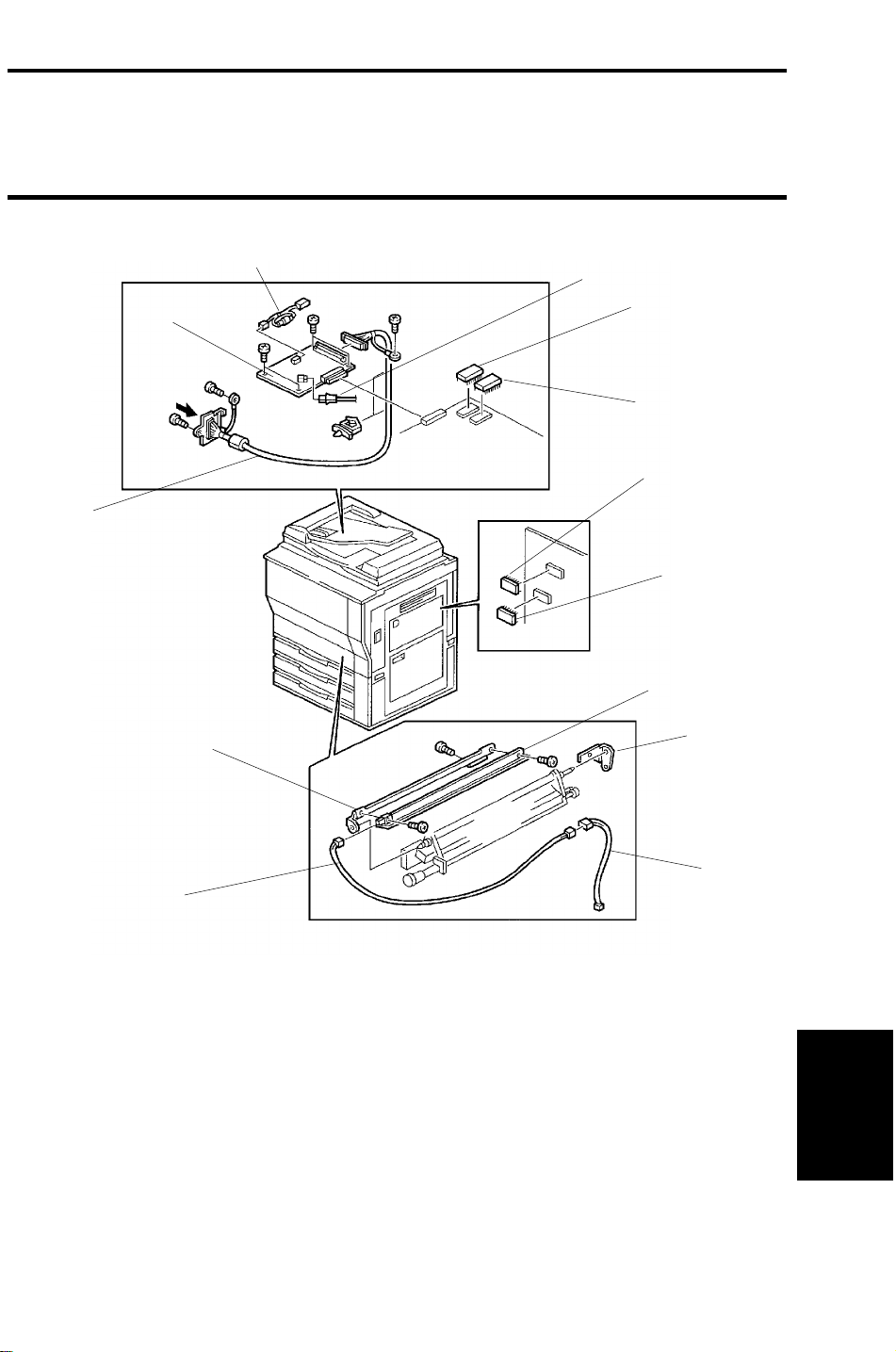
2. COMPONENT LAYOUT
3
2
1
9
4
5
6
7
8
10
11
12
1. Controller Interface Harness
2. Controller Interface Board
3. Fuse Harness
4. Fiber Optics Cable
5. IPU ROM (IC303)
6. IPU ROM (IC309)
7. Main ROM(IC522)
13
8. Main ROM(IC509)
9. PTL Stay
10. PTL (LED Array)
11. PTL Bracket
12. PTL Harness
13. PTL Relay Harness
1
Page 4

ELECTRICAL COMPONENT DESCRIPTION 19 September 1994
3. ELECTRICAL COMPONENT DESCRIPTION
Symbol Name Function Index No.
(See p. 1)
Printed Circuit Board
PCB 1 Controller Interface
Board
Lamp
L1 PTL Reduces the drum potential in non-image
Rerational ROMs
IC303 IPU ROM Processes R/G/B video signals. 5
IC309 IPU ROM Processes R/G/B video signals. 6
IC509 Main ROM Controls the PTL and all copier functions. 8
IC522 Main ROM Controls the PTL and all copier functions. 7
Interfaces input/output data between the
Fiery Controller and the main frame.
areas of the drum, to prevent toner from
jumping to these non-image areas.
2
10
2
Page 5

CONTROLLER
INTERFACE
KIT
19 September 1994 INSTALLATION
4. INSTALLATION
4.1 ACCESSORY CHECK
Make sure that each accessory listed in the following table is in the box. Also
check the condition of each item.
1. Controller Interface Board . . . . . . . . . . . . . . . . . . . . 1
2. IPU ROM (IC303, IC309). . . . . . . . . . . . . . . . . . . . . 1 of each
3. Main ROM (IC509, IC522) . . . . . . . . . . . . . . . . . . . 1 of each
4. Fuse Harness . . . . . . . . . . . . . . . . . . . . . . . . . . . . . 1
5. Fiber Optics Cable. . . . . . . . . . . . . . . . . . . . . . . . . . 1
6. Controller Interface Harness . . . . . . . . . . . . . . . . . . 1
7. PTL . . . . . . . . . . . . . . . . . . . . . . . . . . . . . . . . . . . . . 1
8. PTL Bracket. . . . . . . . . . . . . . . . . . . . . . . . . . . . . . . 1
9. PTL Stay . . . . . . . . . . . . . . . . . . . . . . . . . . . . . . . . . 1
10. PTL Harness . . . . . . . . . . . . . . . . . . . . . . . . . . . . . 1
11. PTL Relay Harness . . . . . . . . . . . . . . . . . . . . . . . . 1
12. Stepped Screw - M3 . . . . . . . . . . . . . . . . . . . . . . . 1
13. Philips Pan Head Screw - M3 x 8 . . . . . . . . . . . . . 1
14. Philips Pan Head Screw - M4 x 8 . . . . . . . . . . . . . 6
15. Screw - M4 x6 . . . . . . . . . . . . . . . . . . . . . . . . . . . . 1
16. Wire Saddle. . . . . . . . . . . . . . . . . . . . . . . . . . . . . . 2
17. Installation Procedure . . . . . . . . . . . . . . . . . . . . . . 1
3
Page 6
INSTALLATION 19 September 1994
4.2 INSTALLATION PROCEDURE
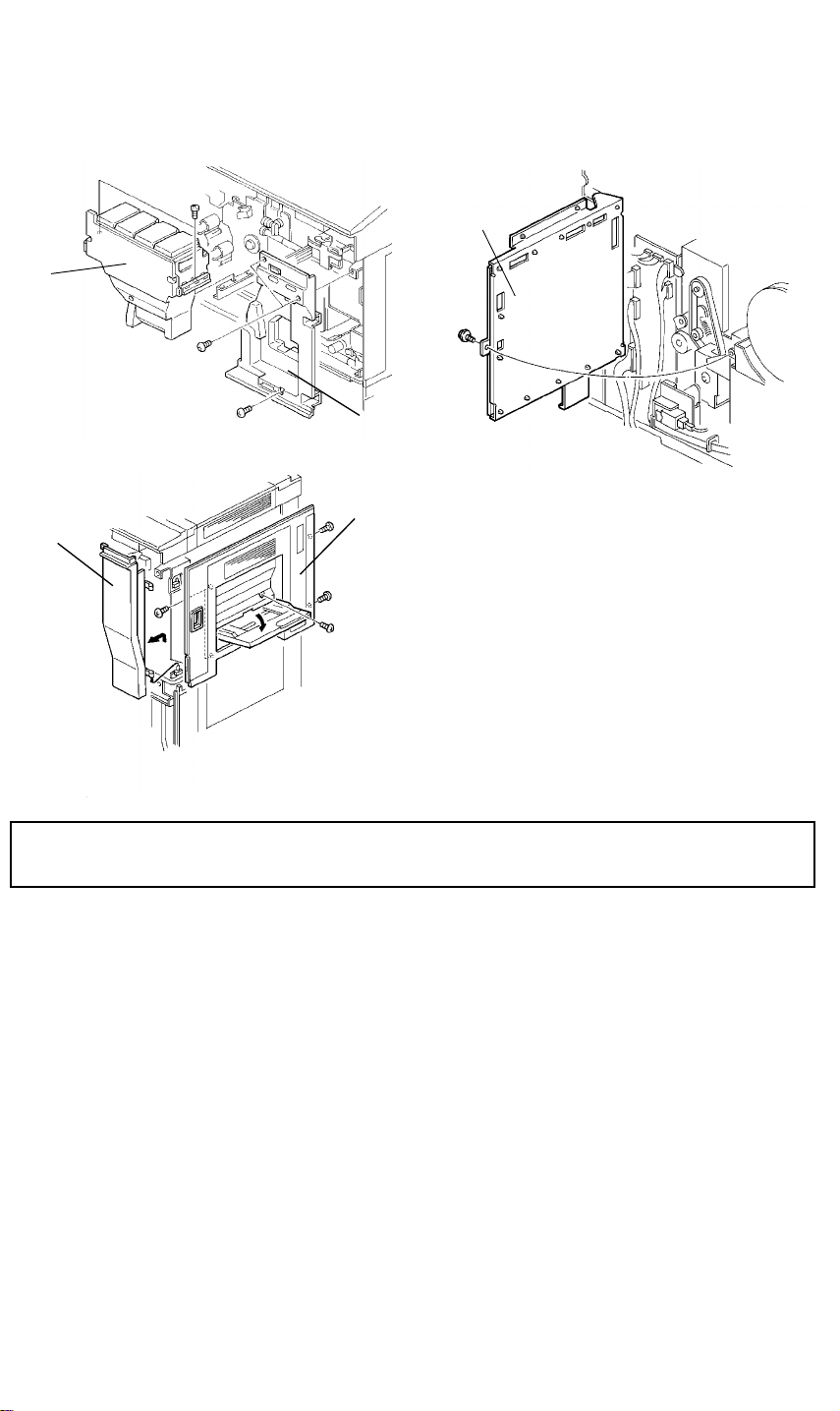
4.2.1 Remove the covers
[D]
[A]
[B]
[E]
[C]
CAUTION: Turn off the main switch and unplug the machine before
starting the following procedure.
1. Open the front doors and remove the toner tank unit [A] (2 screws).
2. Remove the right inner cover [B] (3 screws).
3. Remove the right front door [C].
4. Remove the upper rear cover (4 screws).
5. Remove the lower rear cover (4 screws).
6. Swing out the main board [D] (1 screw).
7. Remove the upper right cover [E] (5 screws).
4
Page 7

CONTROLLER
INTERFACE
KIT
19 September 1994 INSTALLATION
4.2.2 Attach the PTL (Pre-Transfer Lamp) to the belt cleaning unit.
[B]
[H]
[A]
[I]
[G]
[E]
[C]
[F]
[D]
1. Lower the toner collection duct (1 hook).
2. Disconnect the three connectors and free them from the three harness
clamps.
3. Remove the transfer belt stay (5 screws).
4. Remove the belt cleaning unit by pulling it out.
5. Remove the screw [A] on the rear plate of the unit.
6. Attach the PTL bracket [B] with this screw [A].
7. Attach the PTL (LED array) [C] to the PTL stay [D] (M3x8 [E] ,stepped
screw-M3 [F]).
8. Remove the release spring [G].
9. Attach the PTL stay/LED array assembly [H] to the cleaning unit [I] (M4x6
screw).
10. Reset the release spring [G].
NOTE: Don’t set the release spring the wrong way round.
5
Page 8

INSTALLATION 19 September 1994
4.2.3 Route the PTL harness and attach the belt cleaning unit
[E]
[B]
[D]
[C]
[A]
[G]
[F]
[H]
[I]
1. Route the white connector end [A] of the PTL harness [B] from the upper
rear right side of machine through to the rear as shown in the diagram (8
clamps).
2. Run the PTL relay harness [C] (3 clamps) down the rear side and connect
it to the connector [D] and the PTL harness [E].
3. Route the PTL harness [F] through the front side of the machine (8
clamps).
4. Reinstall the belt cleaning unit and connect it to the PTL harness [G].
5. Reinstall the transfer belt stay [H] (5 screws and 3 connectors).
6. Reinstall the toner collection duct (1 hook).
NOTE: Connect the connector of the PTL unit before reattaching the
transfer belt stay. Also, disconnect it after removing the transfer
belt stay.
After reinstalling the transfer belt stay, secure the PTL harness
with the 2 clamps [I] on the transfer belt stay.
6
Page 9

CONTROLLER
INTERFACE
KIT
19 September 1994 INSTALLATION
4.2.4 Install the interface board and harness
[A]
[C]
[F]
[B]
[G]
[E]
[D]
[H]
[I]
1. If the DJF is equipped on the copier, secure the DJF to the scanner unit
with the DJF securing belt [A] as shown.
If the Film Projector Unit is installed on the copier, remove the mirror unit.
2. Remove the two screws [B] at the front of the scanner unit.
3. Remove the two screws [C] at the rear of the scanner unit.
4. Open the scanner unit and set the scanner support bar [D] as shown.
5. Disconnect the shielded flat cable [E] and remove the IPU board cover [F]
(2 long and 5 short screws).
6. Remove the harness cover [G] from the right rear corner.
7. Remove the lower left cover [H] (4 screws). Then remove the cap [I] from
the lower left cover.
7
Page 10

INSTALLATION 19 September 1994
[A]
[C]
[B]
[F]
[D]
[E]
8. Route the harness above the left rail of the 1st tray [A] from the left side
to the rear.
9. Place the controller interface harness bracket [B] on the left side frame
and secure it with the grounding wire (1 screw) [C].
10. Remove the timing belt [D] and install the two harness clamps [E].
11. Route the harness from the bottom to the top as shown [F].
NOTE: Route the harness behind the charge inlet fan duct. Position the
harness near the rear side plate so that the harness won’t touch
any moving parts such as timing belts and motors.
12. Secure the harness with the three harness clamps and reinstall the timing
belt.
8
Page 11

CONTROLLER
INTERFACE
KIT
19 September 1994 INSTALLATION
[C]
[H]
[F]
[I]
[E]
[B]
[G]
[D]
[A]
[J]
[K]
13. Install the controller interface board [A] by connecting it to CN308 [B] of
the IPU board (4 screws).
14. Connect the white 2P connector [C] to CN301 [D] of the controller
interface board via the fuse harness [E].
15. Connect the controller interface harness [F] to CN303 [G] of the controller
interface board. Then secure the grounding wire [H] to the IPU board
bracket (1 screw).
NOTE: Make sure that the connectors are set properly. If not, the copier
might not achieve the ready condition or blank copies might be
made.
16. Connect the fiber optics cable [I] to CN514 [J] on the main control board
and route it to the IPU board area following other fiber cables.
17. Run the fiber optics cable through the harness clamps and connect it to
CN304 [K] of the controller interface board.
9
Page 12

INSTALLATION 19 September 1994
4.2.5 Replace ROMs and reassemble the machine
1. Replace the ROM (IC303) on the IPU board.
2. Replace the ROM (IC309) on the IPU board.
3. Replace the ROM (IC509) on the main board.
4. Replace the ROM (IC522) on the main board.
5. Re-assemble the machine.
4.2.6 Connect to the Fiery and adjust the printer gamma
The printer gamma must be adjusted for both Fiery print mode settings
(halftone and contone).
1. Connect the Fiery controller to the controller interface connector with the
cable provided from EFI.
2. First turn on the copier. When the copier in standing by, turn on the Fiery
controller.
3. Watch the Fiery boot up. When "Press ESC to run Fiery Setup" is
displayed, press the ESC key.
4. Press Enter until the "Enable halftone printing" setting is displayed.
Then select Yes with the "
→" key and press Enter.
5. When the "Default print mode" setting is displayed, select halftone.
6. Press Enter until "Save changes: No/Yes/Quit" is displayed.
7. If you changed either of the settings in steps 4 and 5, select Yes then
press Enter. Otherwise, select Quit then press Enter. The Fiery
continues its startup routine.
NOTE: If you made a mistake during set-up, select No and do the set-up
all over again.
8. When the Fiery controller enters idle mode, press the F4 key to print a
test page.
10
Page 13

CONTROLLER
INTERFACE
KIT
19 September 1994 INSTALLATION
9. Compare the color scales on the test page just printed with the color
scales for halftone in the halftone area of the reference Fiery test chart.
Check the following points on the print out.
1). The 16th levels in each of the 16-grade color test strips (YMCK) are
similar in density to those on the test chart.
2). The 16th level in the 16-grades "PK" (Process Black) scale is similar
to that on the test chart.
10. If the colors on the test page are not acceptable, adjust the
data as follows.
1). Enter the SP mode on the copier.
2). Select "8: Printer".
3). In the "=Letter=" screens (pages 1 and 2) of the SP mode, adjust
the 16th levels for the colors that need adjusting by changing only
the IDMAX setting in the OFFSET column.
NOTE: The IDMAX OFFSET setting should be between 0 and 4.
Do not change the data in the STEP columns; these must remain
at the default settings.
Do not change the H, M, or L settings in the OFFSET column.
Such changes will have no effect on the printout, because the
various colors in the H, M, and L ranges are produced by
dithering (the laser is switched on and off to produce dither
patterns).
4). Exit the SP mode and press the F4 key on the Fiery keyboard.
γ correction
11
Page 14

INSTALLATION 19 September 1994
11. If necessary, repeat the adjustment from step 9. Otherwise, go to step 12.
12. After your adjustment, reboot the Fiery controller to change the printer
mode setting (press Alt-X or the Reset button).
13. Press ESC to enter Fiery Setup and select contone in the "Default print
mode" (refer to steps 3 ~ 7).
14. When the Fiery controller enters idle mode, press the F4 key to print a
test page.
15. Compare the color scales on the test page just printed with the color
scales for contone in the contone area of the reference Fiery test chart.
Check the following points on the print out.
1). The various grades along the color scales are similar in density to
those on the reference test chart.
2). The gray balance of the "PK" test strip is similar to that of the
reference chart.
16. If the color scales on the test page are not acceptable, adjust the
γ
correction data as follows.
1). Enter the SP mode on the copier.
2). Select "8: Printer".
3). In the "=Photo=" screens (pages 3 and 4), adjust the color scales
by changing the
γ data in the OFFSET columns.
Low: Use to adjust levels 1 to 3 of the 16-grade scale.
Middle: Use to adjust levels 2 to 14.
High: Use to adjust levels 13 to 15.
ID MAX: Use to adjust the whole range, including level 16.
Do not change this unless the whole range needs
to be made brighter or darker. The adjustment is
very sensitive, so it is best not to change the
default settings.
Do not change the
γ data in the STEP column from the default
settings.
4). Exit the SP Mode and press the F4 key on the Fiery’s keyboard.
12
Page 15

CONTROLLER
INTERFACE
KIT
19 September 1994 INSTALLATION
17. If necessary, repeat the adjustment from step 14. Otherwise, go on to
step 18.
18. After finishing the adjustment, check with the customer that the mode that
is set up on the Fiery controller is suitable.
13
Page 16

ADDITIONAL SP MODE TABLE FOR PRINTER 19 September 1994
5. ADDITIONAL SP MODE TABLE FOR
PRINTER
②
①
③
①
Item Function Note
①
Factory use only Do not change the STEP values
Adjusts each color image density
(Letter mode rough adjustment)
①
①
②
③
②
①
③
①
in the field.
See Section 4.2.6 (color balance
adjustment) from step 10.
①
①
②
②
③
③
Adjusts each color image density
(Photo mode rough adjustment)
The above diagrams show the default settings.
14
Page 17

CONTROLLER
INTERFACE
KIT
19 September 1994 ADDITIONAL SP MODE TABLE FOR PRINTER
①
③
②
Item Function Note
①
②
③
Adjusts each color image density
(Letter mode, fine adjustment)
Adjusts each color image density
(Photo mode, fine adjustment)
Limits users from the remote terminal. Default: OFF
Do not change these values
in the field.
Do not change these values
in the field.
Do not change these values
when connected to the Fiery
Controller.
The above diagrams show the default settings.
15
 Loading...