

Ricoh cattleya Technical Bulletin cattle

T
echnical
B
ulletin
PAGE: 1/1
Model:
Subject:
From:
Classification:
For the Cattleya fusing unit, “Silicone Oil Type SS” P/No. A2579100 should be used.
Please correct your service manual as follows:
Page 3 -16
Page 5 - 9
Cattleya
Silicone Oil for the Fusing Unit
Technical Service Dept., GTS Division
Troubleshooting
Mechanical
Paper path
Other ( )
After “Step 3”, please add the following:
NOTE: “Silicone Oil Type SS” P/No. A2579100 should be used for this copier.
In the PM table for the fusing unit, please add the following remarks for the column
on silicone oil:
Part information
Electrical
Transmit/receive
Date:
15-Jun-99
Prepared by:
No.:
RA257001
H. Matsui
Action required
Service manual revision
Retrofit information
Remarks: “Silicone Oil Type SS” P/No. A2579100 should be used.
CAUSE
One of the features of the new silicone oil is its (small amount of) low molecular “siloxane”.
This has an effect on the volatility of the oil. At around 150 °C, the volatility of the new
silicone oil is about 1/3 that of the previous silicone oil. This feature prevents the charge
corona wire from getting soiled by the vaporized silicone oil. However, the lubrication
properties of this new silicone oil are the same as those of the old type.
For Cattleya, be sure to use the new type of silicone oil. The new silicone oil has been
used from the first step of the development of Cattleya and therefore the machine is not
designed to operate using the old type of oil. Consequently, it is impossible to predict the
performance under the old type of oil (there are no tests on this available).
NOTE:
1. ”Siloxane” is the name of a chemical compound, which consists of silicon and oxygen.
2. The lubrication properties of a mix between the old and new oils would remain
unaffected. However, the advantage of the new silicone oil over the older type is that
the low volatility will be lost.
RICOH Technical
Bulletin
PAGE: 1/4
Model:
Subject:
From:
Classification:
This RTB contains the necessary information related to the firmware of Cattleya.
Cattleya
Firmware-related Information
Technical Service Dept., GTS Division
Troubleshooting
Mechanical
Paper path
Other ( )
Part information
Electrical
Transmit/receive
Date:
15-Aug-99
Prepared by:
Action required
Service manual revision
Retrofit information
No.:
H.Matsui
RA257002
Modification History of the Cattleya Firmware
The following table shows the modification history of the main control and scanner IPU
firmware for Cattleya. The major modifications of each version of firmware are listed at the
end of this RTB.
Version Production Cut in
Main
Control
Scanner
IPU
1.501 March ‘99 production (Start of the production)
1.502 April ‘99
1.514 May ‘99
1.542 June ‘99
1.561 July ‘99
1.15 March ‘99 production (Start of the production)
1.16 May ‘99
1.19 July ‘99
Approved Firmware for connection with the printer controller E-650
To enable the printer functions using the printer controller E-650, it is necessary to use the
following version or newer.
Main Control : version 1.561
Scanner IPU : version 1.19
Language
The main control firmware containing Spanish, Dutch, Swedish, and Danish has recently
been released. Since the version of this firmware is 1.561, it is necessary to update the
scanner IPU firmware to version 1.19 at the same time for machines produced before July.

RICOH Technical
Bulletin
PAGE: 2/4
Model:
Cattleya
Date:
15-Aug-99
No.:
RA257002
Interchangeability of the firmware
The main control firmware version 1.561 and scanner IPU firmware version 1.19 are not
interchangeable with the older versions unless used as a set. They should be updated at
the same time. When version 1.561 main firmware is used with the scanner firmware older
than version 1.19, or when scanner firmware version 1.19 is used with the main firmware
older than version 1.561, errors in machine operation may be expected.
Recommendation for machines produced before July
It is recommended that the firmware for machines manufactured before July 99 are
updated to main firmware version 1.561 and scanner firmware version 1.19 at installation.
This is because updating to these versions should be done at the same time. If this is not
done, trouble may occur if main or scanner firmware update become necessary in the
future.
Interchangeability of the main board and the scanner IPU board
The part numbers of the main board and the IPU board have been changed due to the
firmware update to ver.1.561 and ver.1.19. (Please refer to MB No. MA257002.) The only
difference between the new and old parts is the version of the firmware.
Because the new firmware is not interchangeable with the older versions, please check the
version of the firmware and update as necessary when replacing the main control board or
the scanner IPU board.
Description Old P/N Firmware Interchan
geability
Scanner IPU A2575135 ver. 1.16
or older
Main (120V) A2575107 ver. 1.542
or older
Main (230V) A2575108 ver. 1.542
or older
x/x A2575137 ver. 1.19
x/x A2575105 ver. 1.561
x/x A2575106 ver. 1.561
New P/N Firmware

RICOH Technical
Bulletin
PAGE: 3/4
Model:
Cattleya
Date:
15-Aug-99
No.:
RA257002
List of Major Modifications
Main Firmware Version 1.502
The following software bug has been corrected:
Some text in the Systems Setting screen on the operation panel display was misaligned.
Main Firmware Version 1.514
The following software bugs have been corrected:
1. When twin color (red and green), poster (2x2), and thick paper modes are selected in
combination, a solid image may appear on the leading edge of the copy.
2. Copy may become solid black when using ADF in ACS mode when making more than
two continuous copies.
3. In machines without an ADF, the operation panel may be locked when removing the
paper waiting for the second side to be copied in the duplex tray.
4. Abnormal image may appear when copying on 13x19 inches paper with an
enlargement ratio of 200%.
5. Erase margin may be abnormal when using A6 paper with European models.
6. Some items were not printed out by the SP data printing function.
Main Firmware Version 1.542
1. Drum motor stop timing has been optimized to prevent the possibility of the transfer
belt surface scratching the OPC drum.
2. On/off timing of the ITB cleaning brush and cleaning blade has been optimized to
prevent toner accumulated on the edge of the blade from falling on the image transfer
belt.
3. The following SP Modes have been added.
SP8-115 Fusing temperature s et t ing for Special Mode Progra m: Copy (for Special Mode 1)
SP8-215 Fusing temperature s et t ing for Special Mode Progra m: Copy (for Special Mode 2)
SP8-315 Fusing temperature s et t ing for Special Mode Progra m: Printer (for Special Mo de 3)
SP8- (130-138) Paper transfer current set ting for Special Mode Program: Copy (for Specia l Mode 1)
SP8- (230-238) Paper transfer curre nt setting for Special Mode Program: Copy (for Specia l Mode 2)
SP8- (330-338) Paper transfer curre nt setting for Special Mode Program: Printer (for Special Mode 3)

RICOH Technical
Bulletin
PAGE: 4/4
Model:
Main Firmware Version 1.561
The following SP Modes have been added
SP8-(140-148)-(01-08) Gamma setting for Special Mode Program: Copy (for Special Mode 1)
SP8-(240-248)-(01-08)Gamma setting for Special Mode Program: Copy (for Special Mode 2)
SP8-(340-343)-(01-08)Gamma setting for Special Mode Program: Printer (for Special Mode 3)
Scanner IPU Firmware Version 1.16
The following software bugs have been corrected.
1. Small no painted area may appear in the image after having painted inside a closed
2. SC326 may appear when making A3 copies in Auto Original Type Select and 400%
3. APS may not function properly immediately after ACC has failed.
Cattleya
loop area.
enlargement modes.
Date:
15-Aug-99
No.:
RA257002
Scanner IPU Firmware Version 1.19
1. The following SP Mode is added :
SP8-(140-148)-(01-08) Gamma setting for Special Mode Program: Copy (for Special Mode 1)
SP8-(240-248)-(01-08)Gamma setting for Special Mode Program: Copy (for Special Mode 2)
SP8-(340-343)-(01-08)Gamma setting for Special Mode Program: Printer (for Special Mode 3)
2. When th e setting is changed from the default (5) to 6, the ACC target density level for
the printer mode (SP mode 4-502-001 to 004) has been changed as follows:
If the setting of ACC target density level for the printer mode (SP mode 4-502-001 to 004,
adjustable range:0 to 10, default setting:5) is changed to 6, the level of ID max will become
greater (20% up for K, 15% up for Y, M, C).
NOTE:
1. The level of ID max will not change, even if the setting is changed to 7, 8, 9, or 10.
2. If ID max is increased, there is a greater tendency for toner scattering to occur in text
areas.

RICOH Technical
Bulletin
PAGE: 1/3
Model:
Subject:
From:
Classification:
This Technical Bulletin contains some important notes concerning the installation of the E650color controller for the Cattleya.
1. Approved Firmware of Cattleya for connection with the E-650printer controller.
To enable the printer functions using the E-650 controller, it is necessary to use the
following version of Cattleya firmware.
Main Control: Ver. 1.561 or new er
Scanner IPU: Ver. 1.19 or newer
Cattleya
Important notes at installation of E-650.
Technical Service Dept., GTS Division
Troubleshooting
Mechanical
Paper path
Other ( )
Part information
Electrical
Transmit/receive
Date:
15-Aug-99
Prepared by:
Action required
Service manual revision
Retrofit information
No.:
RA257003
Chisato Tsuji
If the version is older, please make sure to update the firmware.
For details regarding the Cattleya firmware, please refer to RTB No.
on August 15th, 1999.)
2. EMI Shield installation.
Make sure to intall the EMI shield on the interface unit (“I/F unit”) before installing the
controller interface Type F kit in the copier.
(The EMI shield and the installation procedure sheet are packed with the E-650.)
Tool required: #2 phillips h ea d screwdriver.
Note: Attach an ESD grounding wrist strap and follow standard ESD (electrostatic
discharge) precautions before doing this procedure.
RA257002
(issued
RICOH Technical
)
)
)
Bulletin
PAGE: 2/3
Model:
Cattleya
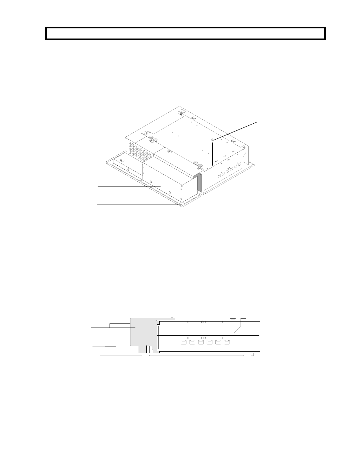
To install the EMI Shield on the I/F Unit.
2-1. Place the I/F unit on a stable static-free surface.
Note: If the I/F unit is already installed in the copier, you may skip this step.
I/F unit left shield cover
Date:
15-Aug-99
No.:
RA257003
Remove this screw
I/F unit bottom view
2-2. Remove and set aside the I/F unit screw indicated in the figure above.
2-3. Unpack the EMI shield and align the EMI shield on the bottom of the I/F unit where the
copier interface board is exposed. Make sure that the EMI shield’s:
Two tabs are outside of the I/F unit
Lip is inside the I/F unit
Other edges are outside the I/F unit’s left shield cover
Placement of EMI Shield
I/F unit (bottom view
Tab (outside
Lib (inside
Tab (outside)

RICOH Technical
Bulletin
PAGE: 3/3
Model:
2-4. Make sure the screw holes line up and replace the screw you removed earlier.
Now you are ready to install the Controller Interface Type F kit and the E-650 controller as
described in the
Cattleya
While replacing the screw, hold the shield against the I/F unit to ensure a tight fit.
E-650 Installation and Service Guide
Date:
.
15-Aug-99
Replace this screw
EMI shield installed
No.:
RA257003
RICOH Technical
C
Bulletin
PAGE: 1/2
Model:
Subject:
From:
Classification:
The positioning of the revolver unit is a critical check item when setting the drum unit in the
upper drawer unit. To prevent any problems similar to the symptom described below,
please release the following information to all technicians in your regions servicing this
machine.
Problem
When the drum unit was set in the upper drawer un it, the devel opment unit was placed at
90 degrees (vertical), which is the development unit removal position. Being in this
position, the drum came in direct contact with the ribs of the development unit upper cover,
causing the drum to be scratched or damaged.
Cattleya
Drum damage at installation
Technical Service Dept., GTS Division
Troubleshooting
Mechanical
Paper path
Other ( )
Part information
Electrical
Transmit/receive
Date:
31-Aug-99
Prepared by:
Action required
Service manual revision
Retrofit information
No.:
H. Matsui
RA257004
Action required
The above problem would normally happen at the time of installation or developer
replacement. To prevent the drum from being damaged, the revolver unit must be set to
its home position before the drum unit is set in the upper drawer unit.
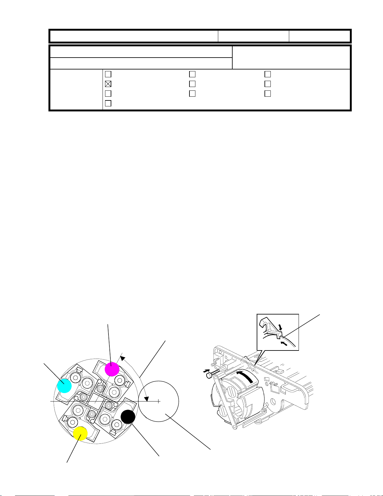
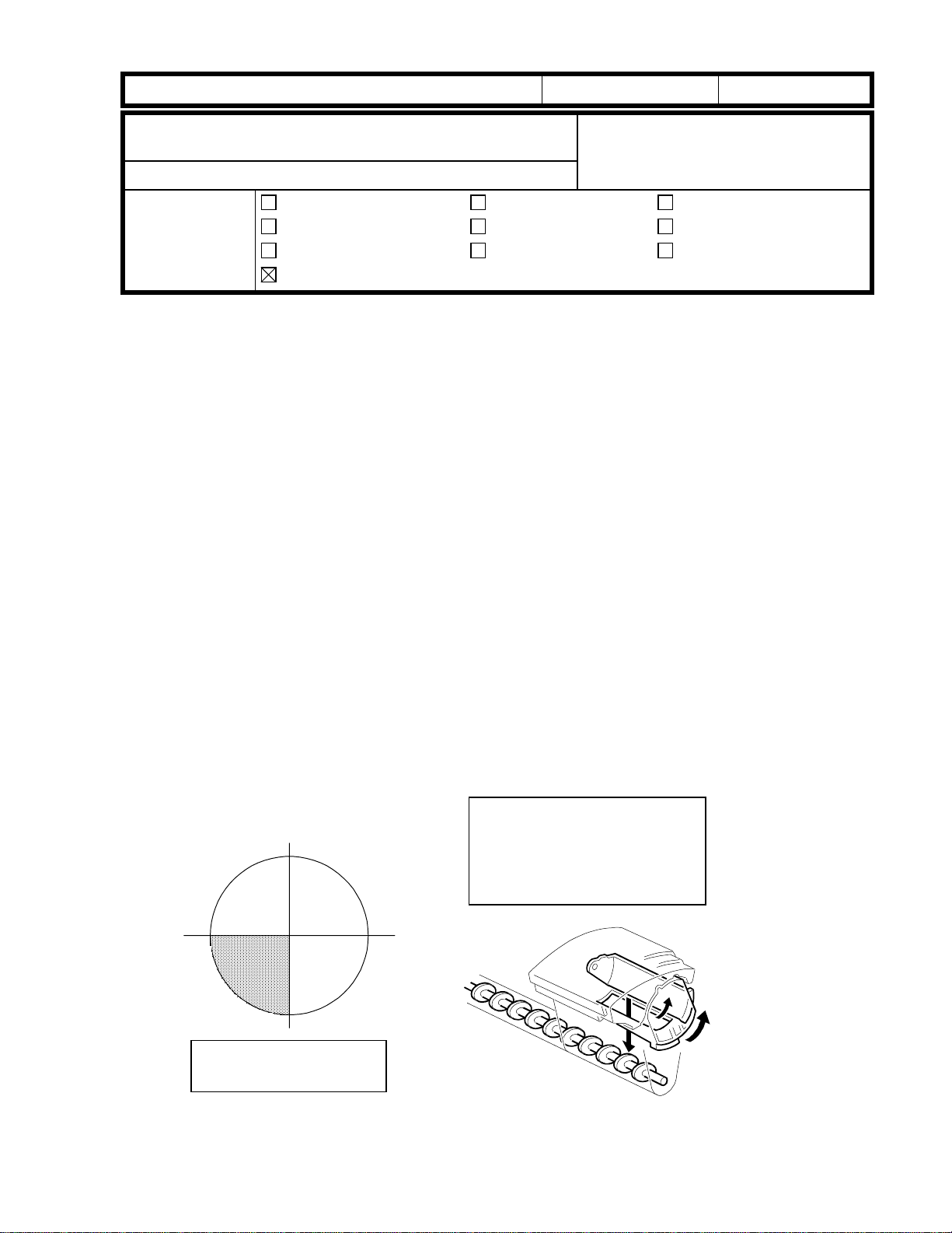
Revolver Home Position
As shown in the following illustration, the magenta development roller should be positioned
at an angle of 60 degrees (from horizontal). When rotating the revolver unit, you can see
the cut-out [A] in the wheel, which locks the revolver unit in the home position.
M
60 degrees
[A]
Y
Revolver home position
K
OPC drum
RICOH Technical
Bulletin
PAGE: 2/2
Model:
Additional Information
In addition to the above information, please note the following remarks for when the
revolver unit is set in the machine:
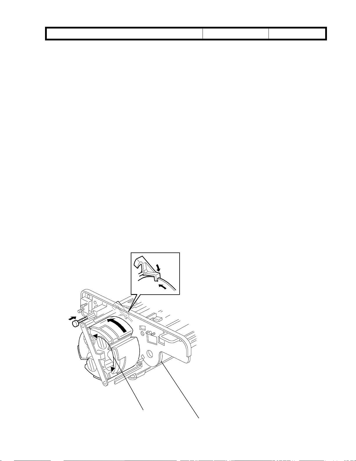
1. Revolver unit
If the gears on the mainframe and revolver unit are not engaged firmly, this may result in a
gap between the revolver unit frame and copier frame (thus the unit will not be properly
set). This also may cause the gears to be damaged when the revolver starts rotating. To
ensure that the gears are properly engaged, it is necessary to manually fit (i.e. lock) the
gears together by manipulating the revolver unit back and forth (slightly) as shown in the
illustration (arrow [A]). This should be done while holding the toner hoppers.
2. Drum unit
To ensure that the gears between the drum and drum shaft properly engage, the flange [B]
of the OPC drum must be pushed toward the back of the machine. (This is explained on
S/M page 6-11.)
Cattleya
Date:
31-Aug-99
No.:
RA257004
Since the vibration generated from the image transfer belt drive section is transmitted to
the drum section, this vibration may interfere with drum rotation if the gears are not
properly engaged. This causes banding on the image (at 1.7 mm intervals).
[A]
[B]
RICOH Technical
Model: Cattleya Date: 15-Oct-99 No.: RA257005
Bulletin
PAGE: 1/2
Subject:
near the leading edge
From:
Classification:
Dirty or colored background in the area
Technical Service Dept., GTS Division
Troubleshooting
Mechanical
Paper path
Other ( )
Prepared by:
Part information
Electrical
Transmit/receive
M. Furusawa
Action required
Service manual revision
Retrofit information
SYMPTOM
Dirty or colored background appears in the area near the leading edge.
A slightly pale image or normal ima ge appears in the other areas towards the trailing edge.
(The width of the area with this dirty or colored background varies.)
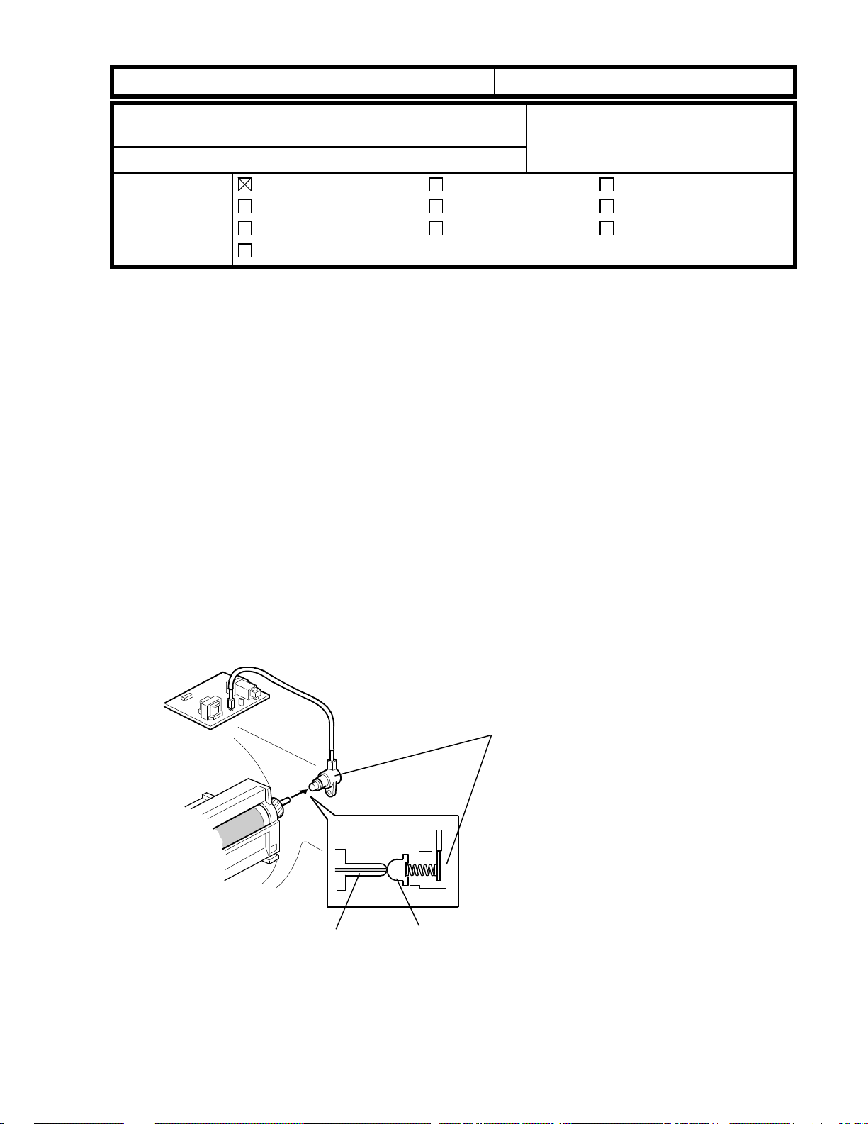
CAUSE
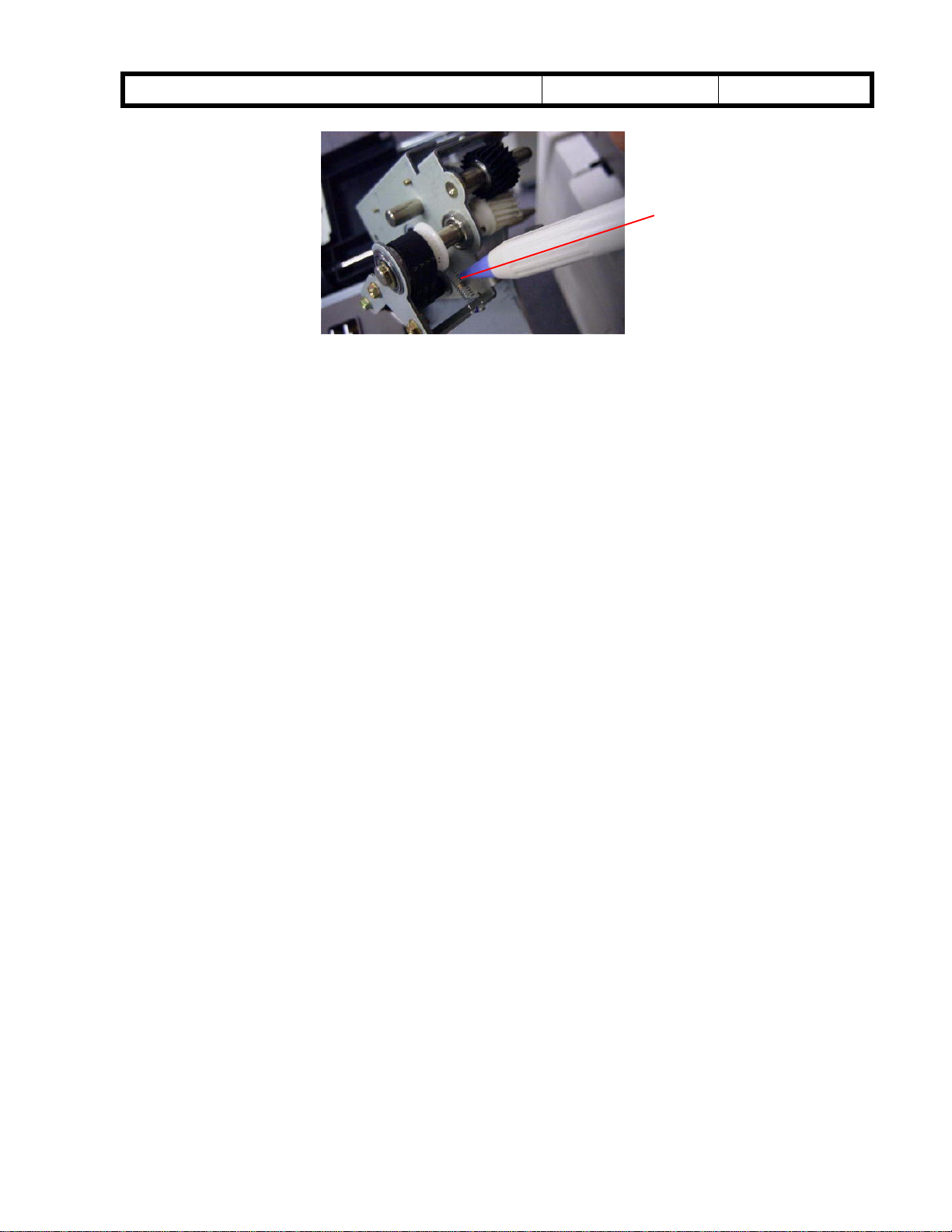
The development bias terminal is pushed against the development input shaft by a spring
to ensure proper terminal contact when the development unit reaches the copying position.
When the terminal does not move smoothly, poor contact of the development bias terminal
results at the beginning of development of the latent image (dirty background will occur
under these conditions).
When the contact between the terminal and the development input shaft is not as poor, the
image becomes slightly pale (or normal if contact is good).
Development Input Shaft
Development Bias Terminal
Terminal

RICOH Technical
Model: Cattleya Date: 15-Oct-99 No.: RA257005
Bulletin
PAGE: 2/2
ACTION
Pull out the revolver/drum drawer and clean the development bias terminal.
Turn the terminal counterclockwise then clockwise (more than ten turns each).
Push the terminal repeatedly more than ten times so that terminal movement is smooth.
Reassemble the machine and check the copy quality.
If the above action is not successful (this is a very rare case), replace the development
bias terminal with a new one (P/N A2573298).
If the new part is not available, loosen the upper screw that secures the development
bias terminal to the copier rear side frame.
- Objective Machines -
The development bias terminal was previously modified from a one-screw type to a
two-screw type, effective from around May, 1999.
If the two-screw type terminal is secured too tightly, a slight deformation of the
terminal casing can occur.
The machines in the field that could potentially exhibit this problem were produced
from May to July, 1999, because the bias terminal was not inspected in these
machines.
However, the occurrence rate is expected to be very low.
Countermeasure for machines in mass-production:
The bias terminals have been inspected at the factory since August, 1999.
To ensure proper contact between the bias terminal and the development input shaft
without the inspection, a modification of the development bias terminal has been applied to
the production line from October, 1999 (the inner diameter of the terminal casing has been
slightly increased).
The part number has been changed from A2573297 to A2573298.

RICOH Technical
Model: Cattleya Date: 15-Oct-99 No.: RA257006
Bulletin
PAGE: 1/2
Subject:
from the leading edge
From:
Classification:
Horizontal black or magenta line at 106 mm (4.17”)
Technical Service Dept., GTS Division
Troubleshooting
Mechanical
Paper path
Other ( )
Prepared by:
Part information
Electrical
Transmit/receive
M. Furusawa
Action required
Service manual revision
Retrofit information
SYMPTOM
The following only occurs in thick paper mode and OHP mode.
A horizontal line appears at 106 mm from the leading edge.
The line is normally colored Black but the last one of the multiple copy run is colored
Magenta (in the Full Color mode).
CAUSE
When the drum speed is slowed in thick pape r/OHP mode, loose screws that fasten the
flywheel supporter to the drum shaft cause the drum to stop for a very short while.
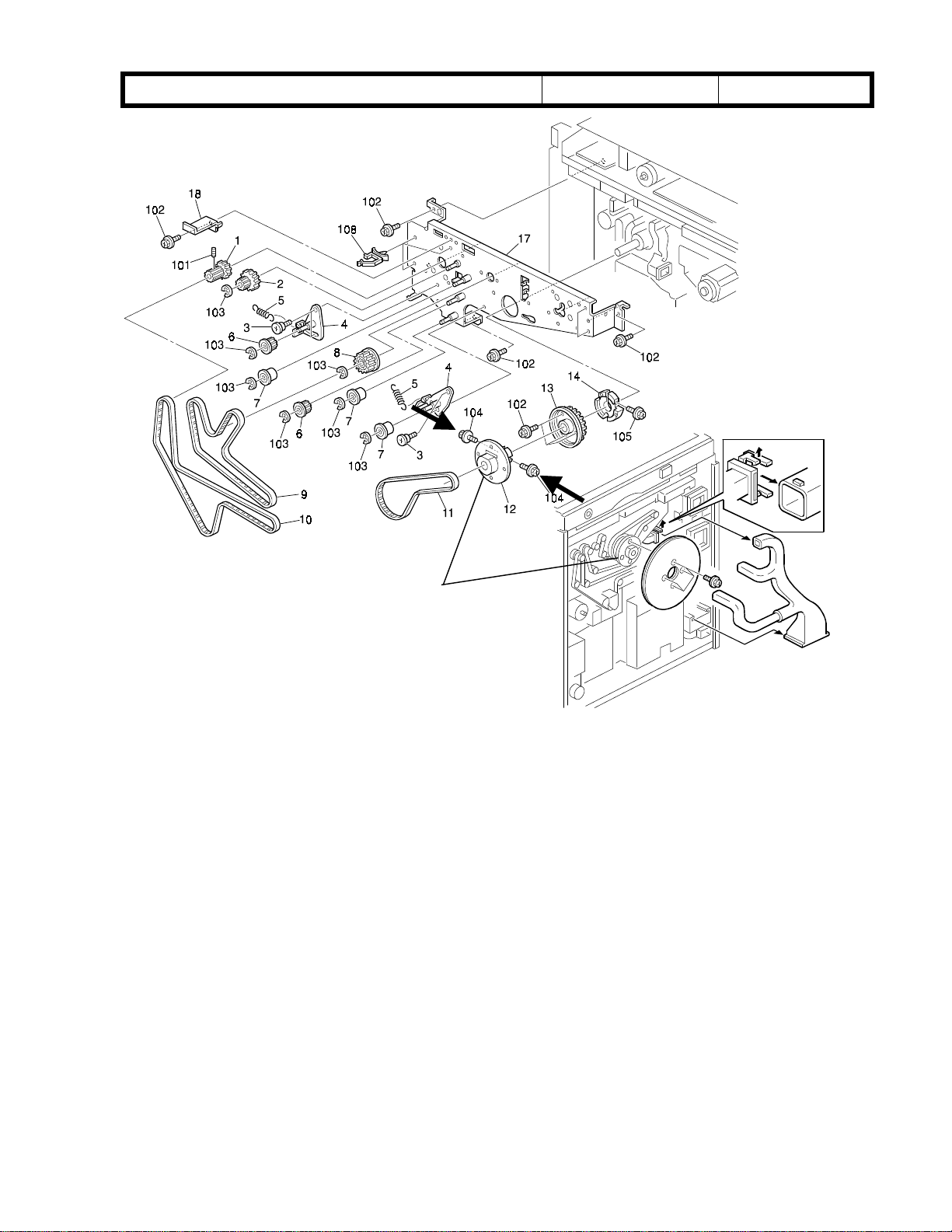
ACTION
Remove the large and small flywheels and tighten the screws for the flywheel supporter.
(Refer to the illustration on the next page.)
The flywheel supporter has four cut-outs for the screws. Two out of the four cut-outs have
a flat surface (from May production: the cut-in serial numbers were not controlled). Make
sure that the screws are positioned on these flat surfaces, especially after disassembling
these areas.
RICOH Technical
Model: Cattleya Date: 15-Oct-99 No.: RA257006
Bulletin
PAGE: 2/2
Flywheel Supporter

RICOH Technical
Model: Cattleya Date: 15-Oct-99 No.: RA257007
Bulletin
PAGE: 1/1
Subject:
From:
Classification:
SC450 (Paper transfer bias current error)
Technical Service Dept., GTS Division
Troubleshooting
Mechanical
Paper path
Other ( )
Part information
Electrical
Transmit/receive
Prepared by:
Action required
Service manual revision
Retrofit information
M. Furusawa
SYMPTOM
SC450 is displayed when the main switch is turned on or during a copy/print cycle.
CAUSE
Paper transfer belt shift clutch (P/N AX210067) failure.
Some of these shift clutches may overrun the stop position over time.
When the cl utch is energized, it rotates for 180 degrees and stops. If it overruns its stop
position, the paper transfer belt unit drops and SC450 is indicated.
ACTION
Replace the paper transfer belt shift clutch with a modified one (AX210076).
Clutch modification:
The clutch shaft has been modified to prevent the possibility of the overrun.
The electric power of the clutch has been increased from 8 W to 15 W to ensure that
the armature plate is properly pulled when the clutch is energized.
This modification has been applied to the production line from the end of July, 1999.
AX210067 à AX210076

RICOH Technical
Model: Cattleya Date: 15-Oct-99 No.: RA257008
Bulletin
PAGE: 1/1
Subject:
From:
Classification:
Magenta image
Technical Service Dept., GTS Division
Troubleshooting
Mechanical
Paper path
Other ( )
Part information
Electrical
Transmit/receive
Prepared by:
Action required
Service manual revision
Retrofit information
M. Furusawa
SYMPTOM
Only the Magenta image is transferred to the copy paper in the Full Color mode (only the
last color image is transferred in the 2C and 3C modes).
CAUSE
Image transfer belt cleaning shift clutch (P/N AX210067) failure.
When this clutch overruns, the image tran sfer belt cleaning blade remains in contact with
the image transfer belt.
With the exception of the last color toner, the cleaning blade wipes off the toner on the
image transfer belt before the toner image is transferred to the copy paper.
ACTION
Replace the image transfer belt shift clutch with a modified one (AX210076).
Note:
paper transfer belt shift clutch.
Clutch modification:
The image transfer belt cleaning shift clutch has the same part number as the
AX210067 à AX210076
The clutch shaft has been modified to prevent the possibility of the overrun.
The electric power of the clutch has been increased from 8 W to 15 W to ensure that
the armature plate is properly pulled when the clutch is energized.
This modification has been applied to the production line from the end of July, 1999.
RICOH Technical
Model: Cattleya Date: 15-Oct-99 No.: RA257009
Bulletin
PAGE: 1/2
Subject:
(Image transfer belt cleaning unit position error)
From:
Classification:
n
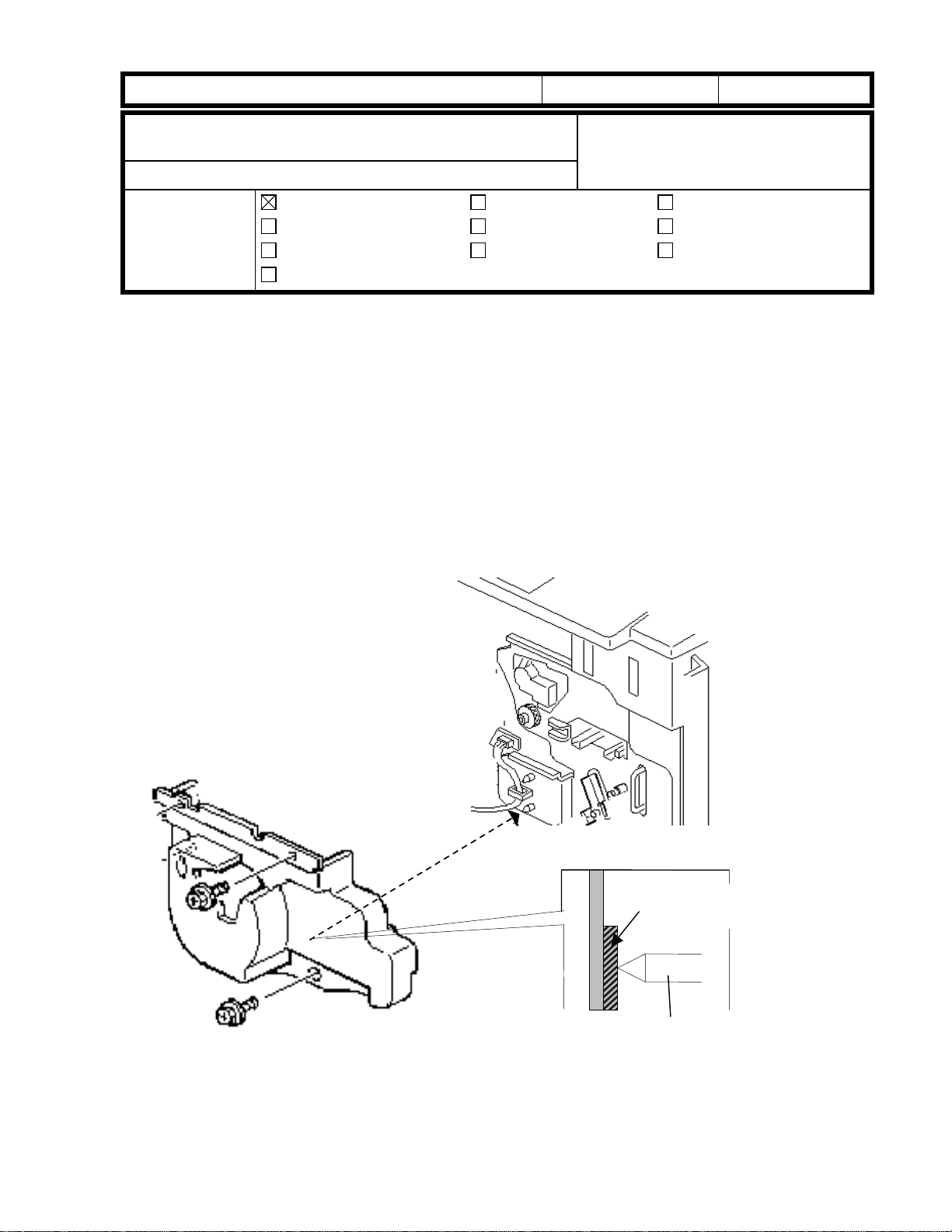
Symptom:
If operations are attempted on the machine after the revolver cover has been removed, the
SC457 indication lights up (error in the setting of the belt cleaner).
Procedure:
Setting the Revolver Cover:
In order to ensure the accurate setting of the image transfer belt cleaning unit, there
-
SC457
Technical Service Dept., GTS Division
Troubleshooting
Mechanical
Paper path
Other ( )
Part information
Electrical
Transmit/receive
When checking machine operation without the revolver cover:
is a rubber plate on the rear side of the revolver cover to push the lower positioning
pin of the image transfer belt cleaning unit (refer to the illustration below).
Prepared by:
M. Furusawa
Action required
Service manual revision
Retrofit information
Rubber Plate
Lower Positioning Pin
If performing tests (e.g. on machine operation) after the revolver cover has been
-
removed, please do so after pushing the lower positioning pin and properly setting
the unit.
RICOH Technical
Model: Cattleya Date: 15-Oct-99 No.: RA257009
If the machine does not operate normally after the installation of the revolver
cover:
Check to see if the touch and release mechanism of the blade/brush of the image
transfer belt cleaning area is working properly.
If working properly, there is a problem with the belt cleaning HP sensor.
-
If not working properly, there is a problem with the belt cleaning shift clutch.
-
If such abnormalities occur with this sensor and/or clutch, check to see that the
sensors are clean and that the connectors are properly connected to the sensors.
Also be aware that it is possible for the belt mark detector to be malfunctioning as well.
Summary of Causes:
1. Faulty setting of the image transfer belt cleaning unit.
2. Problem with the touch and release mechanism of the blade/brush of the image
transfer belt cleaning unit.
3. Malfunction of the belt mark detector of the image transfer belt unit.
Bulletin
PAGE: 2/2
n
Loose knob for the transfer faceplate
Symptom:
When the knob of the transfer faceplate is loose, SC457 is displayed.
Cause:
Due to a mistake when setting the transfer faceplate, the drum knob loosens and the
setting position of the image transfer belt cleaning unit shifts.
Procedure:
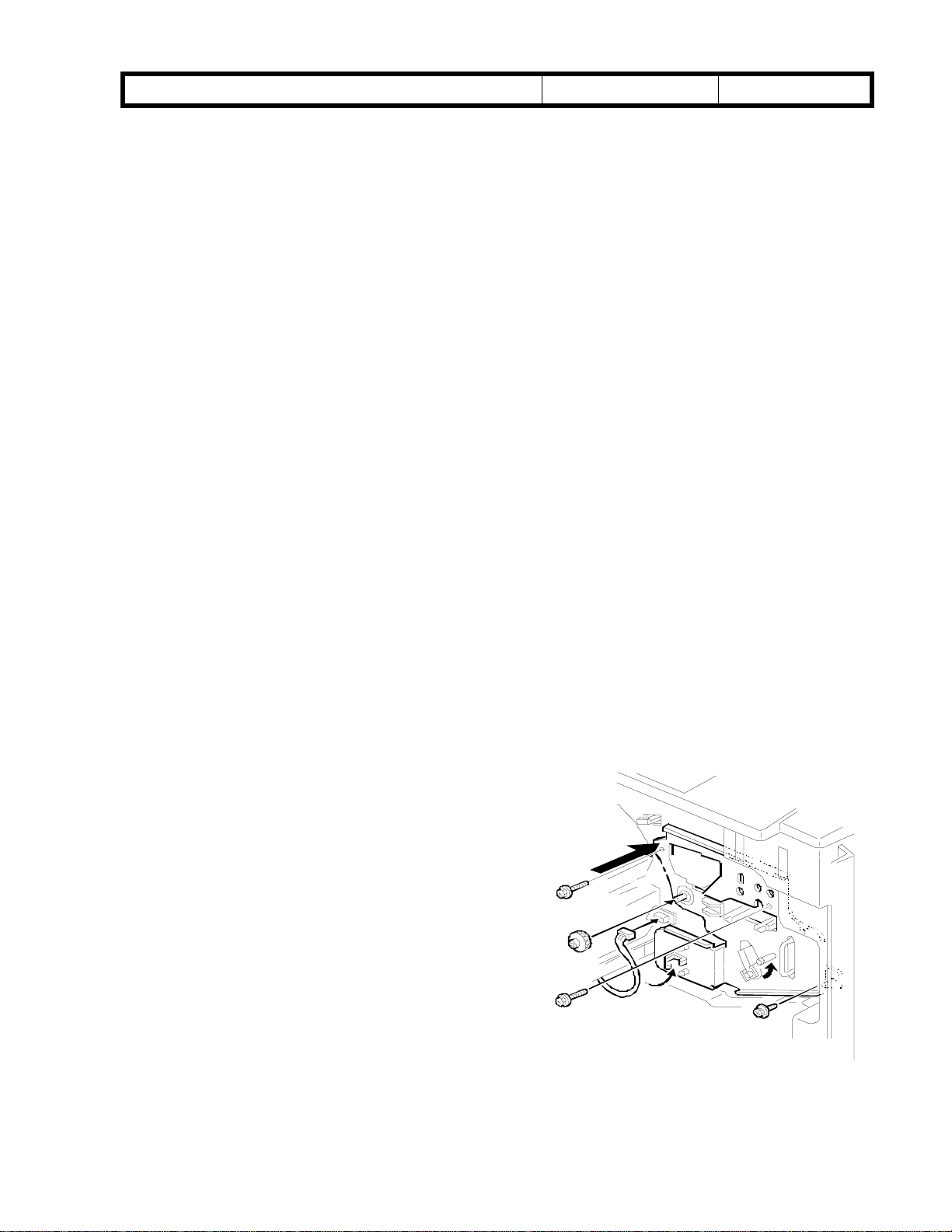
Reinstalling the transfer faceplate:
1. Remove the transfer faceplate.
2. Reinstall the transfer faceplate and
tighten the knob [1].
3. Push ing the upper lef t part of the
faceplate against the revolver/drum
drawer, tighten the three screws in the
following order: [2], [3], [4].
4. Re-tighten the knob.
Note:
transfer belt tension lever as is (until
the drum rotates along with the
knob).
Re-tighten this knob with the
[ 2 ]
[ 1 ]
[ 4 ]
[ 3 ]
RICOH Technical
Model: Cattleya Date: 15-Oct-99 No.: RA257010
Bulletin
PAGE: 1/5
Subject:
From:
Classification:
Random Jitter
Technical Service Dept., GTS Division
Troubleshooting
Mechanical
Paper path
Other ( )
Part information
Electrical
Transmit/receive
Prepared by:
Action required
Service manual revision
Retrofit information
M. Furusawa
SYMPTOM
Jitter bands appear at random positions on copies.
For an A4 (LT) lengthwise or A3 (DLT) copy, one jitter band is observed (at first
occurrence). Later, two or three may be observed on A3 (DLT) copies.
Once it appears, this jitter is likely to occur continuously for certain copy jobs.
CAUSE
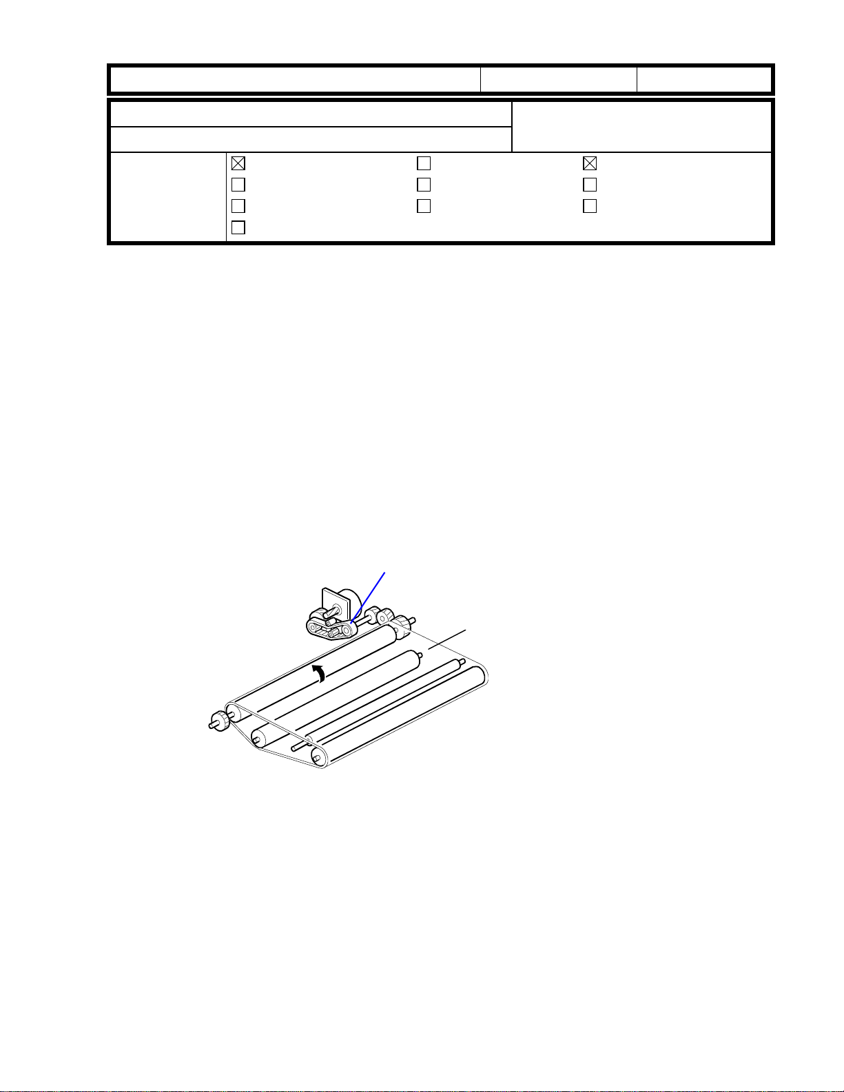
The timing belt that drives the paper transfer belt disengages from the cogs of the timing
pulley (jumping one cog over) when the movement of the tension roller bracket becomes a
little worse.
It has been found that the tension spring for the timing belt does not have enough strength
to prevent this random jitter.
Timing Belt that
drives the Paper
Transfer Belt
Paper Transf er Belt
SOLUTION
Replace the tension spring with a stronger one at installation or at the next visit to the
customer site.
The strength of the original spring (P/N A2573997) is 1.0 Newton and the new one (P/N
AA060836) is 2.3 Newtons.
The color of the new tension spring is also different (i.e. old: silver, new: black).
(The new springs will be provided free of charge.)
RICOH Technical
Model: Cattleya Date: 15-Oct-99 No.: RA257010
- Objective Machines -
The Cattleya produced from May to early August, 1999 are the objective machines.
The details are shown in the following table.
(About 20% of the objective production machines have been modified in Japan before
the shipment.)
Bulletin
PAGE: 2/5
Objective machines
A257-15 No Yes Yes No
A257-17 No Yes Yes Yes (first 53 units)
A257-22 No Yes Yes No
A257-26 Yes Yes Yes No
A257-27 Yes Yes Yes No
A257-29 Yes Yes Yes No
A257-55 --- --- No No
A269-15 No Yes Yes No
A269-17 No Yes Yes No
A269-22 No Yes Yes No
A269-26 Yes Yes Yes No
A269-27 Yes Yes Yes No
A269-29 Yes Yes Yes No
A269-55 --- --- No No
NOTE:
The material of timing belt that drives the paper transfer belt has been changed from
chloroprene rubber (P/N A2573993) to polyurethane rubber (P/N AA043285). This is
to increase its resistance to ozone, thereby increasing durability as well.
This modification has been applied to the production runs from May, 1999 (from June
for machines with destination code -15, -17, and -22).
The new spring has been applied to production from August 4, 1999.
:
May
Production
Yes = Objective machines, No = Non-objective machines
June
Production
July
Production
August
Production
The following table explains the possibility of the problem for each combination.
Tension Spring
Old (A2573997) New (AA060836)
Timing
Belt
Old (A2573993) No problem Lifetime of the timing belt
may be reduced.
New (AA043285) Random jitter may occur. No problem
RICOH Technical
Model: Cattleya Date: 15-Oct-99 No.: RA257010
Bulletin
PAGE: 3/5
Checking and Replacement Procedure
Since about 20% of the objective production machines have been modified with the new
tension spring, the following 2 pages explain how to distinguish between the old and new
springs, then how to replace the old spring with the new one.
This procedure will take about 5 minutes.
Procedures to prevent random jitter
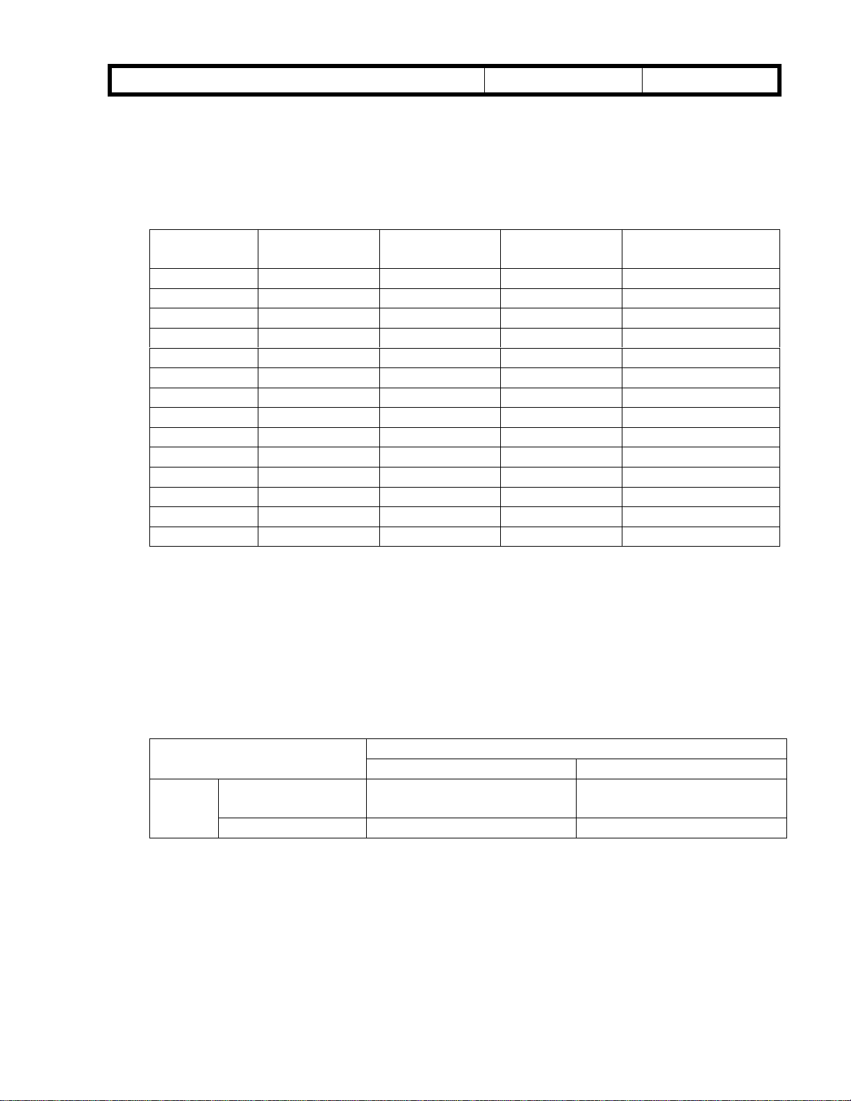
= Check Procedure =
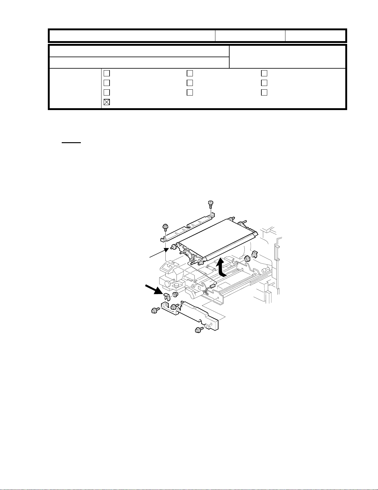
1. Open the front covers and pull out the fusing/transfer drawer.
2. Remove the separation plate (1 shoulder screw and 1 screw).
Separation Plate
3. Check the color of the tension spring of the PTB (paper transfer belt) drive belt.
If the color is black, reassemble the machine sin c e this will indicate that the spring is a
new one.
If the color is silver, go onto the next procedure “Spring Replacement Procedure”.
Tension Spring
RICOH Technical
Model: Cattleya Date: 15-Oct-99 No.: RA257010
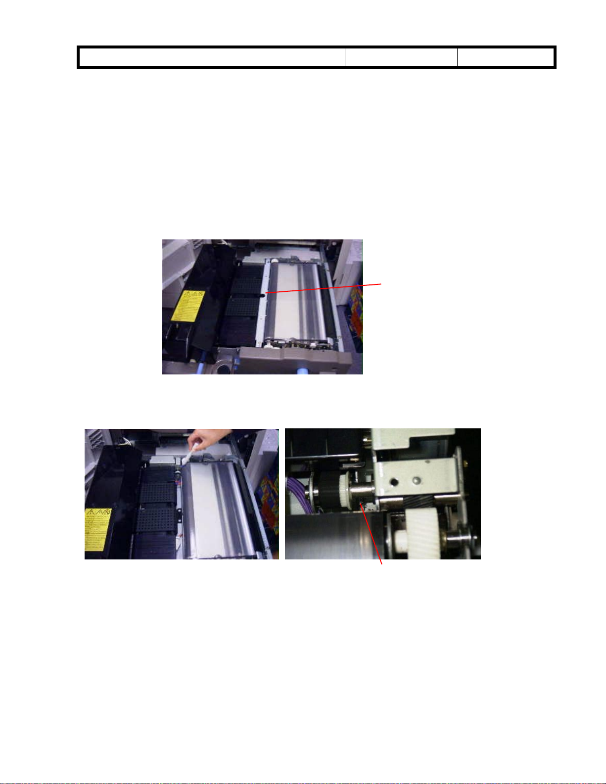
= Spring Replacement Procedure =
1. Press the stoppers on both sides of the fusing/transfer drawer rail and pull out the
drawer.
2. Lift and remove the fusing unit.
Fusing/Transfer
Drawer
3. Remove the transport unit (2 snap rings and 2 bushings, keep the connector coupled),
turn it around, and place it on the drawer as shown in the picture.
Bulletin
Fusing Unit
PAGE: 4/5
Transport Unit
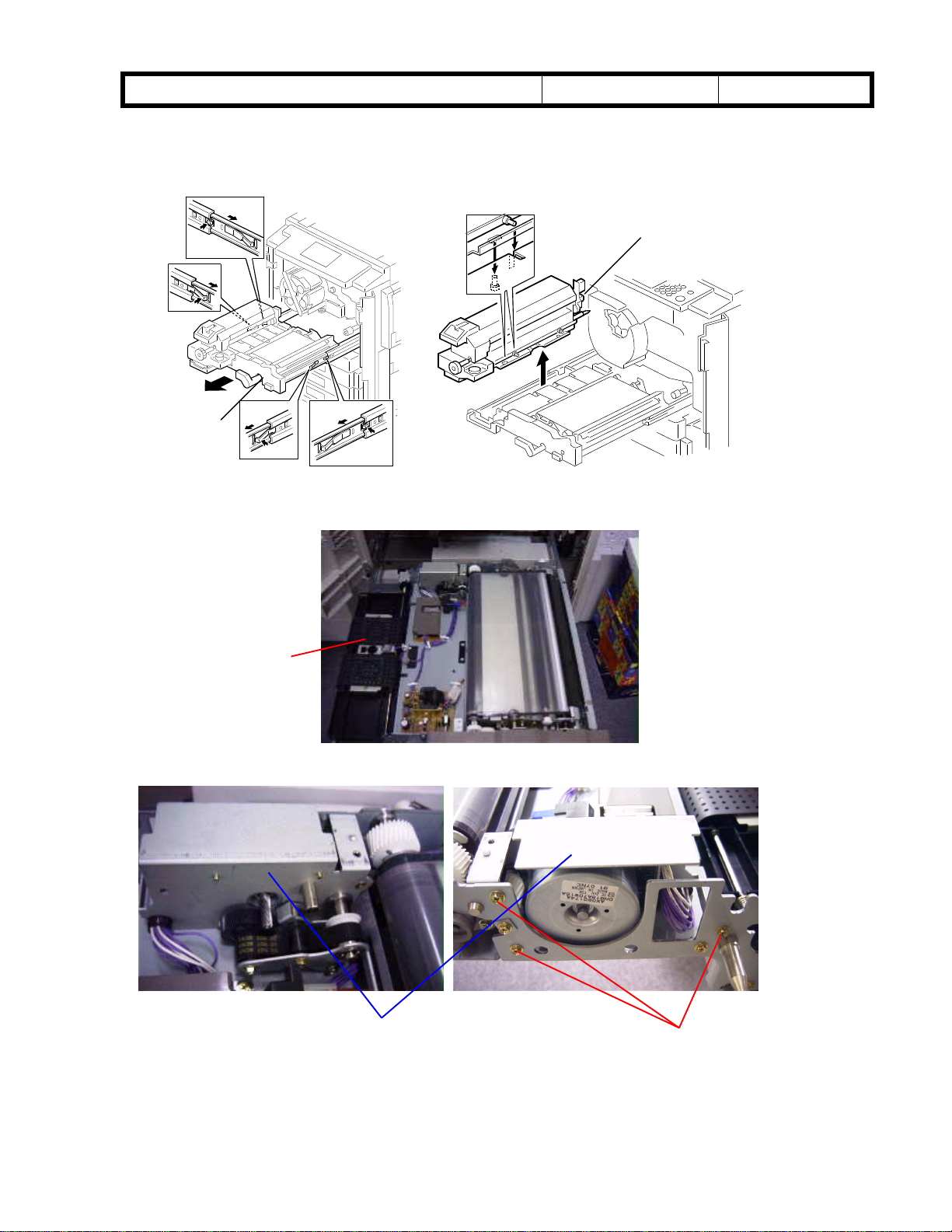
4. Remove the paper transfer belt motor assembly (3 screws).
- Front view - - Rear View -
Transfer Belt Motor
Assembly
Screws
RICOH Technical
Model: Cattleya Date: 15-Oct-99 No.: RA257010
5. Remove the tension spring (silver) and install a new one (black).
6. Reassemble the machine.
Bulletin
Tension Spring
PAGE: 5/5
RICOH Technical
Bulletin
PAGE: 1/1
Model: Cattleya Date: 15-Oct-99 No.: RA257011
Subject:
without toner end indication
From:
Classification:
Notes for when removing the toner cartridge
Technical Service Dept., GTS Division
Troubleshooting
Mechanical
Paper path
Other (Technical Tips)
Prepared by:
Part information
Electrical
Transmit/receive
M. Furusawa
Action required
Service manual revision
Retrofit information
Notes for when removing the toner cartridge without toner end indication
If the toner cartridge (which is not empty) is removed from the toner cartridge
replacement position, the cartridge lever may not turn smoothly when reinstalling the
toner cartridge. If the cartridge lever is not completely turned to its lock position, toner
may scatter from the toner hopper.
To prevent the above possibility, follow the following procedure:
1. Remove the revolver cover.
2. Rotate the revolver unit until the cartridge you wish to remove is in the removal
position (lower left, looking from the front). See the illustration below.
Note:
If the Cyan cartridge is removed in this position, it is possible to reinstall the
revolver clamp for machine transportation.
3. Tap the toner cartridge near the cartridge lever (e.g. with a handle end of a
screwdriver) and empty the toner into the cartridge from the hopper.
4. (In this position), remove the toner cartridge after having closed the cartridge
shutter. (Make sure that the shutter is completely shut).
5. Clean the shutter area of the cartridge with a vacuum (as well as the silver tape on
the reverse side).
6. Rotate the revolver clockwise to set the toner cartridge to its proper position.
7. After cleaning the area around the shutter (of the hopper), make sure that the
shutter can be moved easily. After closing the shutter completely, set the cleaned
cartridge.
Press the lock pin and turn the
shutter completely.
Clean the sponge seal around
the opening of the cartridge as
well.
Toner Cartridge
Replacement Position
RICOH Technical
Model: Cattleya Date: 15-Oct-99 No.: RA257012
Bulletin
PAGE: 1/1
Subject:
From:
Classification:
Notes when installing the paper transfer unit
Notes when installing the paper transfer unit
Technical Service Dept., GTS Division
Troubleshooting
Mechanical
Paper path
Other (Technical Tips)
Note:
When installing the paper transfer unit, make sure that t he snap ring is set in the
groove of the paper transport belt drive roller shaft.
Otherwise, the following problems may occur:
* SC456 (Paper transfer unit position error)
* Damage to the paper transfer belt
Part information
Electrical
Transmit/receive
Prepared by:
Action required
Service manual revision
Retrofit information
M. Furusawa
Paper Transfer
Belt Drive Roller
Shaft
Snap Ring

RICOH Technical
Model: Cattleya Date: 15-Oct-99 No.: RA257013
Bulletin
PAGE: 1/2
Subject:
Double Transfer Image Mechanism
From:
Classification:
The following two items are additional information (detailed explanation of the
specifications/features).
1. Image rotation in combination with other functions:
Additional Information for the Image Rotation and
Technical Service Dept., GTS Division
Troubleshooting
Mechanical
Paper path
Other (Additional Information)
Image rotation is available under the following conditions.
(1) When “Image Rotation ON” is selected in the "General Features" section of the
User Tools.
(2) When "Auto Paper Select" is selected at the operation panel.
(3) When paper of the same size as the original on the exposure glass is set in the
paper tray perpendicular to the original.
(4) When the Color Mode selected at the operation panel is B&W or Single Color.
Part information
Electrical
Transmit/receive
Prepared by:
M. Furusawa
Action required
Service manual revision
Retrofit information
The "Image Rotation" cannot be performed in the following copy modes:
Area editing mode
Ø
Auto Reduce/Enlarge mode
Ø
(à Possible with Main firmware Ver. 1.572 or later)
Poster mode
Ø
Image Shift mode
Ø
Combine mode
Ø
Book mode
Ø
Image creation mode
Ø
Image overlay
Ø
Film projector
Ø
Staple mode
Ø
2. Conditions for the Double Transfer Image Mechanism
The conditions for the Double Transfer Image Mechanism are as follows:
(1) Copy paper size: A4 sideways (11” x 8
(2) Copy mode: Full Color mode or 1C mode
The copying speed with the Double Transfer Image Mechanism is 10 cpm for Full
Color and 40 cpm for 1C mode.
”) or smaller
1/2

RICOH Technical
Model: Cattleya Date: 15-Oct-99 No.: RA257013
The Double Transfer Image Mechanism in the Full Color mode is not available
with the following functions (even if the above conditions are satisfied):
Margin adjustment
Ø
Centering
Ø
Cornering
Ø
Series copy
Ø
Duplex (2 sided à 2 sided, Book à 2 sided)
Ø
Image overlay
Ø
Poster mode
Ø
Projector mode
Ø
Bulletin
PAGE: 2/2
Note:
sideways (11” x 8
The copying speed of the Full Color mode is 5 cpm. This also applies to A4
”) or smaller.
1/2

RICOH Technical
Model: Cattleya Date: 15-Oct-99 No.: RA257014
Bulletin
PAGE: 1/2
Subject: Main Firmware ver1.572 Information Prepared by:
From:
Classification:
This RTB contains the necessary information related to the main control board firmware
ver 1.572 NA/EU/EU2/EU3 for Cattleya.
Technical Service Dept., GTS Division
Troubleshooting
Mechanical
Paper path
Other ( )
Part information
Electrical
Transmit/receive
H.Matsui
Action required
Service manual revision
Retrofit information
Language
The main control board firmware contains the following languages.
Ver1.572NA: US English, French, Spanish
Ver1.572EU: UK English, French, German, Italian
Ver1.572EU2: Spanish, Dutch, Swedish, Danish
Ver1.572EU3: Norwegian, Portuguese, Polish, Czech
NOTE:
Along with installing the above firmware, it is necessary to update the scanner IPU
firmware to version 1.19 or newer in machines produced before July. If main firmware
version 1.572 is used with the scanner firmware older than version 1.19, errors in machine
operation may occur.
RICOH Technical
Model: Cattleya Date: 15-Oct-99 No.: RA257014
Bulletin
PAGE: 2/2
Contents of the software change
1 “Copies” or “Developments” is displayed on the counter display (when the Counter Key
is pressed).
“Copies” is displayed for a machine with the copy counter set.
“Developments” is displayed for a machine with the development counter set.
NOTE: This change is available only when “English” has been selected as the
operating language.
2. The confirmation button on rhe operation panel is changed from “OK” to “Confirm”
3. The full color sorting setting button in “Duplex/ADF/Sorter” mode in “Copier Feature”
mode in the User Tools is changed from “On” / “Off” to “Off”/ “On”. This is because the
default setting of Full color sorting is “On”.
4. “Image rotation” and “Auto Reduce/Enlarge” can be used at the same time.
5. “Area editing” and “Auto Reduce/Enlarge” can be used at the same time.
NOTE:
Due to software modifications 3, 4, and 5 mentioned above, the operating instructions for
the Cattleya also need to be modified. This will be effective within the month of October.
Errata will be included in the operating instructions. We would like to recommend that
copies of the errata be provided to customers updating to ver 1.572 or newer (please refer
to the following page). The errata can also be printed out from the attached PDF file
CattleyaErrata2.pdf
(
).
Errata
This manual contains some misprints and should be corrected as follows:
P.158 Add You can also change the Auto Reduce/Enlarge setting during area editing.
P.165 The entry in the combination chart for Auto Reduce/Enlarge and “n” should read “✩” and not “×”.
P.198 Full Color Copy Sorting is turned on by default (not off as stated).
P. 56 Add
Auto Off Mode
This machine automatically turns itself off 60 minutes after the last copy or
print job has finished. If you wish to make copies when the machine is in
Auto Off mode, press the operation switch.
Reference
For how to change the default interval that the machine waits before entering
Auto Off mode, see “Auto Timer”on page 191.
Note
The Auto Off timer does not take effect in the following cases:
• When there are originals on the exposure glass or in the document feeder.
• When there are copies in the bins of the sorter stapler.
• While the machine is making copies.
• When a paper misfeed has occurred.
• When a cover is open.
• When a service call message is displayed.
 Loading...