


echnical Bulletin
T
PAGE: 1/3
Model:
Subject:
From:
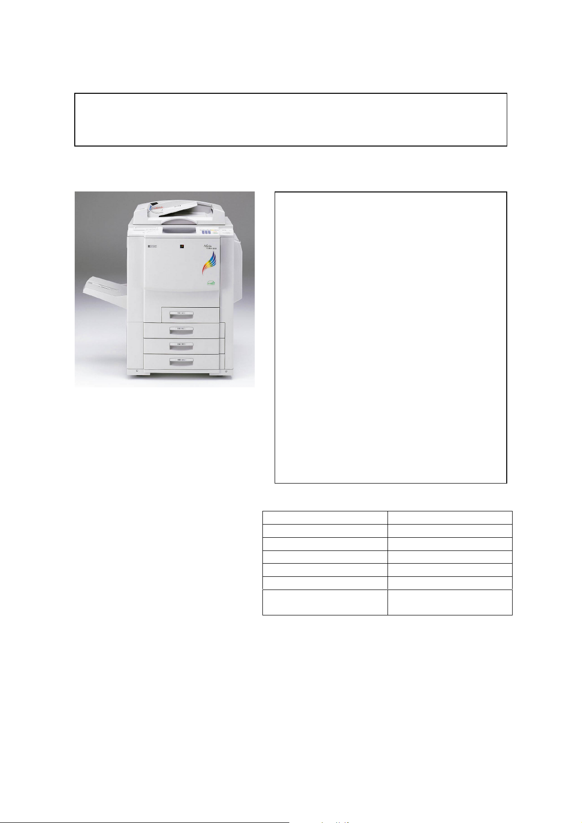
Cattleya 2
Main ROM upgrade for Cattleya2
Technical Services Dept., GTS Division
Classification:
Troubleshooting
Mechanical
Paper path
Other ( )
Part information
Electrical
Transmit/receive
Date:
26-Feb-01
Prepared by:
No.:
RB023001
H. Matsui
Action required
Service manual revision
Retrofit information
Symptom
Paper jams with the sorter stapler jogging function can occur under the following
conditions:
1. When ST33 (20 bin S/S) is used with Cattleya 2 (B023).
NOTE: If it is used for Cattleya 1(A257/A269), this will not occur.
2. When LT (11"X8 1/2") sideways is used when making 2 or more copies of an original.
Cause
The S/S main ROM software cannot compensate for the higher copy speed of Cattleya 2.
The timing of the jogger function and paper feeding does not match that of Cattleya 2.
Solution
When installing the ST33 on Cattleya 2, replace the S/S main ROM with ver "G" or newer.
The ROM version of the S/S main board can be viewed with copier SP7-801-005. The last
digit (for example G) indicates the ROM version. Version G can also be used for Cattleya1.
The part number of this new main ROM is A8315111.

echnical Bulletin
T
PAGE: 2/3
Model:
Program upgrade in mass production
The main ROM upgrade (ver G) has been applied from the first January 2001 production
run for each S/S. The cut-in serial numbers are as follows:
A831-17: H141130001 (see NOTE-1).
A831-26: 3T60110001 (see NOTE-2).
A831-55: L0551XXXXXX (see NOTE-3).
NOTE
1. "H14" is the prefix number. The 4th digit refers to the production year (1 = 2001). The
5th and 6th digits refer to the production month (13=January, 14=February, ........,
23=November, 24=December).
2. "3T6" is the prefix number. The 4th and 5th digits refer to the production month
(01=January, 02=February,........,11=November, 12=December). The 6th digit refers to the
production year (1 = 2001).
3. "L055" is the prefix number, The 5th digit refers to the production year (1 = 2001) and
the 6th and 7th digits refer to the production month (01=January,
02=February,........,11=November, 12=December). Because there are currently no A831-
55 models in production, there is no cut-in S/N at the moment. Please note that although
the Cattleya 2 has no Lanier model at present, there are cases in which A831-55 is used
with models other than Lanier.
Cattleya 2
Date:
26-Feb-01
No.:
RB023001
For the A831-17 model, machines with the following S/N have already been upgraded at
the factory:
H1402400031
H1402400050
H1402400054 to 57
H1402400059 to 63
H1402400068 to 69
H1402400076
H1402400090
H1402400117 to 154
<<Service parts>>
Service parts will be changed as follows:
S/S main board: A8315100 to A8315110 interchangeability: X/O
EPROM: A8315103 to A8135111 interchangeability: X/O
NOTE: The new main board and EPROM can also be used for the S/S which is installed
on the Cattleya 1.

echnical Bulletin
T
PAGE: 3/3
Model:
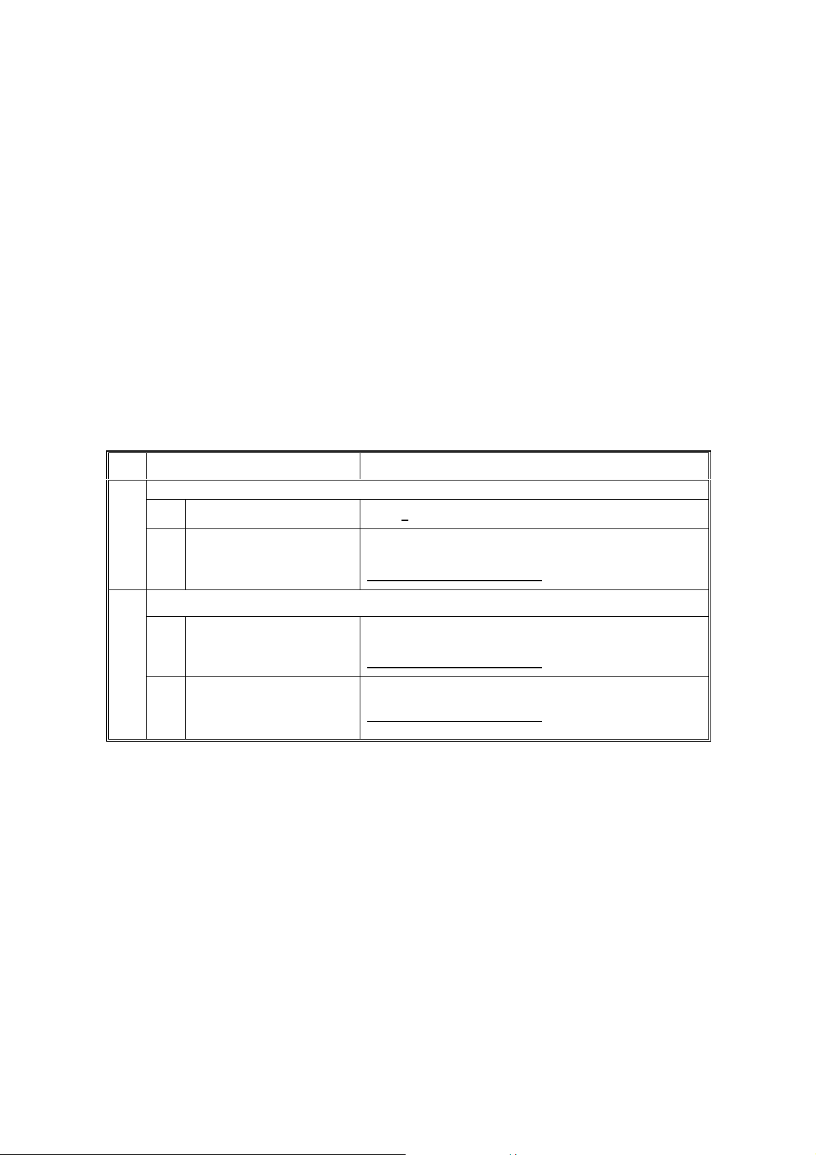
S/S main ROM replacement procedure
1. Remove the rear cover [A] (4 screws).
2. Replace the main ROM [B] with ver "G" or newer. The part number of this new main
ROM is A8315111.
3. Confirm the ROM version with copier SP7-801-005. The last digit (for example G)
indicates the ROM version.
Cattleya 2
Date:
26-Feb-01
[A]
No.:
RB023001
[B]
echnical Bulletin
T
PAGE: 1/2
Model:
Subject:
From:
Cattleya2
Anti-static Brush & Transport Belt
Technical Services Dept., GTS Division
Classification:
Troubleshooting
Mechanical
Paper path
Other ( )
Part information
Electrical
Transmit/receive
Date:
18-May-01
Prepared by:
No.:
RB023002
H.K.
Action required
Service manual revision
Retrofit information
SYMPTOM
It was found during production line tests that in duplex copy mode, the reverse side of the
copy paper may sometimes stick to the upper plate when the paper passes through the
transport belt unit.
CAUSE
A charged static electricity buildup on the transport belt surface repels the reverse side of
the copy paper.
SOLUTION
Temporary solution on the production line
Two anti-static brushes have been attached to the transport left stay from the first
production lot (B0233880, Parts Catalogue page. 77, index 1).
Final solution on the production line
The material of the transport belt has been changed from a non-conductive to a conductive
one. The part number has been changed as follows:
Old part
number
AA040023 AA040031 TRANSPORT BELT
Cut-in serial numbers
B02315 H6310200001
B02317 H6310200051
New part
number
Description Q’ty Int Page Index Note
2X/O
71 8
B02319 H63103xxxxx
B02322 H6310200181
B02326 4G40210001
B02327 H6310200264
B02329 H6310300570

echnical Bulletin
T
PAGE: 2/2
Model:
Remarks for machines produced before the above serial numbers:
If the old transport belt (AA040023) is replaced with the new part (AA040031) in machines
before the modification, remove the two anti-static brushes from the machine. This is
because the extra anti-static brushes can adversely affect copy quality in these older
machines.
Cattleya2
Date:
18-May-01
No.:
RB023002
118±1mm
Transport Left Stay
126±1mm
Anti-static Brushes

echnical Bulletin
T
PAGE: 1/1
Model:
Subject:
From:
Classification:
Cattleya 2 Date: 24-May-01 No.: RB023003
Cattleya 2 Basic Tips
Technical Services Dept., GTS Division
Troubleshooting
Mechanical
Paper path
Other ( )
Part information
Electrical
Transmit/receive
Prepared by:
Action required
Service manual revision
Retrofit information
Tim. Okajima
Overview
This document is designed to allow field service representatives to do the following:
1. Easily access necessary troubleshooting and information very quickly
2. Customize maintenance programs for customers according to their needs and the
machine performance levels / capabilities.
Please keep this document accessible whenever you are servicing the Cattleya 2 in the
field. Later, this document will be updated based on your comments and other field
information.
Note:
As the customize maintenance program is a new concept and this document is a trial
version, we will not provide you with this kind of document for other models. If this will be
accepted and useful in the field, we will consider developing it for other models.
15 May, 2001 Basic Tips for Cattleya 2
Basic Tips for Cattleya 2
Contents
1. Specifications & Adjustments
1-1. Blank Margin
1-2. Registration
1-3. Magnification
1-4. Banding
1-5. Jitter
1-6. Hue / Density Consistency
1-7. Thick Paper Handling
2. Customized Maintenance Program (CMP)
2-1. Overview
2-2. Know the ma chine capability
2-3. How the CM P works
2-4. Procedure
Appendix A: Test patt er ns
Appendix B: SP mo des
Appendix C: SC Cod es
Appendix D: CMP Check Sheet
1st Issued on May 15, 2001
Issued by GTS, Ricoh Co. Ltd.
1

15 May, 2001 Basic Tips for Cattleya 2
Summary
This document is design ed t o al low field service representat ives to do the following:
1. Easily access necessary troubleshooting and information very quickly.
2. Customize maintenance programs for custo m ers according to their needs and the
machine performance lev els / capabilities.
Please keep this document accessible whenever you are servicing the Cattleya 2 in t he field.
Later, this document will be updated based on your comments a nd ot her field information. So
please feel free to contact us about this document.
2
15 May, 2001 Basic Tips for Cattleya 2
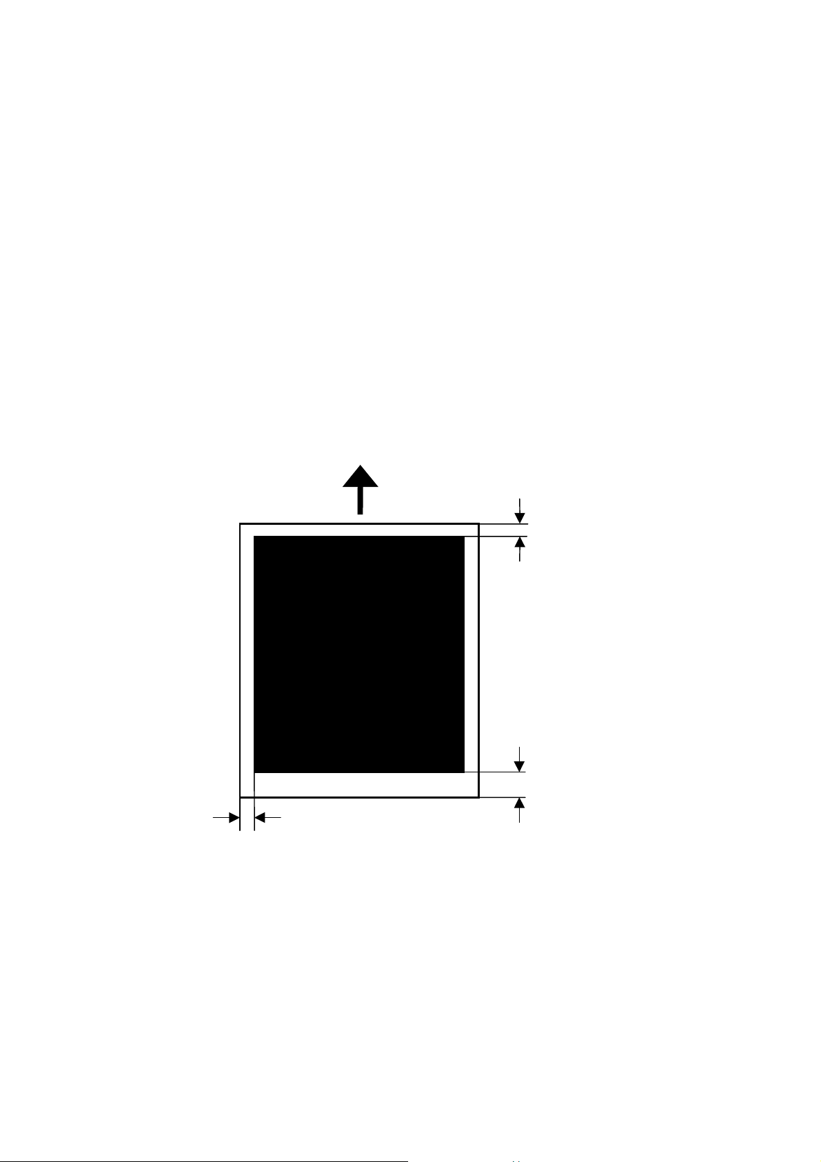
1. Specifications & Adjustments 1-1. Blank Margin
Definition
The blank margin at the leading edge is needed to help paper separate in the fusing unit and
also assists the margin in trimming the effective image area. With the current laser copier
technology, the leading edge margin must be created to prev ent paper jams (not adjustable
in the field).
Specification
Leading edge: 4mm ± 2mm
Trailing edge: 2mm ± 2mm (4mm ± 2mm in case of Thick 1 a nd 2 modes)*
Side edge: 2mm ± 2mm (maximum 4mm when sum both left and right side).
*Note: In both the Thick Mode 1 a nd 2, t here is 4mm blank margin at the lead ing edge
(predecessor model was 2mm). This is to eliminate blurred images which may
occur at the trailing edge due t o pot ential paper holding problems with the new
paper transfer roller system.
Side edge
Paper feed direction
Leading edge
Trailing edge
Competitor Information
Cattleya 1: Trailing edge in think mode: 2 mm+-2mm; the others are same as
those of the Cattleya 2.
Canon CLC1150: Leading edge: 8mm
Xerox DC1250: Trailing edge: 4mm, but smear ed image can be seen at the trai li ng
edge
3

15 May, 2001 Basic Tips for Cattleya 2
Related SP modes
SP2XXX (Drum)
2
Sub-scan/Main-scan margin adjustment
101
1 Sub-scan: Leading edge:
2
3 Sub-scan: Leading edge:
4 Sub-scan: Leading edge:
5 Sub-scan: Trailing edge:
6 Sub-scan: Trailing edge:
7
8 Sub-scan: Trailing edge:
9 Main-scan: Leading edge Adjust the leading margin (operator side). (Screen C,
10 Main-scan: Trailing edge Adjusts the trailing margin. (Screen C, SP9-703)
11
Mode Number Function / [Setting]
Normal
Sub-scan: Leading edge:
Thick 1
Thick 2
OHP
Normal
Thick 1
Sub-scan: Trailing edge :
Thick 2
OHP
Sub-scan: Auto 2nd side:
Trailing edge of 1st side
Adjusts the margin perpendicular to the front edge.
(Screen C, SP9-703)
[–4.0 to 4.0 mm / 0 / 0.1 mm/step]
Adjusts the margin perpendicular to the back edge.
(Screen C, SP9-703)
[–3.0 to 10.0 mm / 0 / 0.1 mm/step]
SP9-703)
[–2.0 to 5.0 mm / 0 / 0.1 mm/step]
[–2.0 to 5.0 mm / 0 / 0.1 mm/step]
Adjusts the trailing margin for the first side of duplex
copies. (Screen C, SP9-703)
[–3.0 to 10 mm / 0 / 0.1 mm/step]
4

15 May, 2001 Basic Tips for Cattleya 2
1-2. Registration
Definition
The registration is determined by t he paper start timing at the registration roller an d t he laser
start timing, both of which can b e adjusted by SP mode.
If you make the paper start timing earlier, t he i ma ge is moved toward the trailing edge.
Conversely, if you make it l at er, the image is moved toward the leading edge.
Note: If the timing is ma de t oo early or too late, this can c ause a paper jam.
Specification
Leading edge registration
Margin of error with recommended paper:
0 ± 1.5mm (full size or reduction mode)
0 ± 1.5mm x M (Enlargement ratio: M)
Margin of error with
0 ± 2.0mm (full size or reduction mode)
0 ± 2.0mm x M (Enlargement ratio: M)
Margin of error in Duplex mode with suggested paper weights:
(17g/m2-105g/m2)
0 ± 2.0mm (full size copy)
0 ± 2.0mm x M (Enlargement ratio: M)
Side to side registration
Margin of error with recommended paper and suggested paper weights:
1.5 ± 0.5 mm. < 4 mm total
Competitor Information
NA
* Suggested paper weights: Pa per included in the original pool of design target pap er weights,
i.e. is expected to work wel l w it h t he machine.
64g/m2 – 256g/m2 for Tray 2, 3, or LCT, 64g/m2 - 105g/m2 for Tray 1.
suggested paper weights *:
5
15 May, 2001 Basic Tips for Cattleya 2
Related SP modes
SP1-XXX (Feed)
1
001
002
Troubleshooting
The crop mark positions on the 1
Mode Number/Name Function / [Setting]
Leading Edge Registration
1 Normal paper
2OHP
3 Thick paper 1
4 Thick paper 2
5 Duplex
6 Second sheet, Half speed
7 Second sheet, 1/3rd speed
Side-to-Side Registration
1 By-pass
2Tray 1
3Tray 2
4Tray 3
5Tray 4
6 2nd side
7LCT
st
and 2nd faces do not match with duplex printing from the
Adjusts the leading edge registration by changing the
timing of the registration clutch. (Screen A, SP7-903)
[+7 to –7 / 0.0 / 0.1 mm/step] IAJ
Specification: 4 ± 1 mm
Thick paper 1 is listed as Thk on the screen.
Thick paper 2 is listed as Super Thk.
Adjusts the side-to-side registration by changing the laser
start position (main scan). (Screen A, SP1-236)
[+9 to –9 / 0.0 / 0.1 mm/step] IAJ
Specification: 1.5 ± 0.5 mm. < 4 mm total
controller.
1. Make sure that both the leading edge and side to side registrations of the 1st side in
Duplex printing are within specification. I f they are not, adjust them using the SP modes
described above.
2. Make duplex prints with crop marks and adjust the regist ration of the 2
nd
face using SP1-
001-005 (Duplex) and SP 1-002-006.
6
15 May, 2001 Basic Tips for Cattleya 2
1-3. Magnification
Definition
The margin of error for sub-scan magnification is twice as large as that of main scan
magnification. This is because sub-scan magnification is affect ed by the variations in p aper
feed speed (paper feed motor), in contrast to the relatively high accuracy of the image
processing unit (main scan mag.).
Specification
Margin of error:
Main Scan Direction: ± 0.5% or less
Sub Scan Direction: ± 1.0% or less
Competitor Information
NA
Related SP modes
SP2-XXX (Drum)
Mode Number Function / [Setting]
2
Main scan magnification adjustment
1 Copy mode DFU [0] (Screen D, SP9-703)
112
2 Print mode
Sub-scan magnification adjustment
1 Copy mode
113
2 Print mode
Troubleshooting
NA
Adjusts the magnification along the main scan direction
for printer mode (Screen D, SP9-703)
[–1.0% to +1.0% / 0 / 0.1/step]
Adjusts the magnification along the sub-scan direction for
copy mode (Screen D, SP9-703)
[–1.0% to +1.0% / 0 / 0.1/step]
Adjusts the magnification along the sub-scan direction for
printer mode (Screen D, SP9-703)
[–1.0% to +1.0% / 0 / 0.1/step]
The screen displays “FsynchMagAdj PRINTER”.
7
15 May, 2001 Basic Tips for Cattleya 2
1-4. Banding
Definition
Lighter or darker bands appear perpe ndicular to the paper feed direction at a fixed interval.
The possible causes are:
! Curves develop in the trans f er belt (areas wrapped around rollers)
! Drum with areas already exposed t o l ig ht
! Un-even development roller rotation speed
Specification
No specification is available for banding. I n addition, it is not possib le t o completely elimin at e
banding with current laser printing t echnology. Please refer to the i mag e sample section for
the banding level.
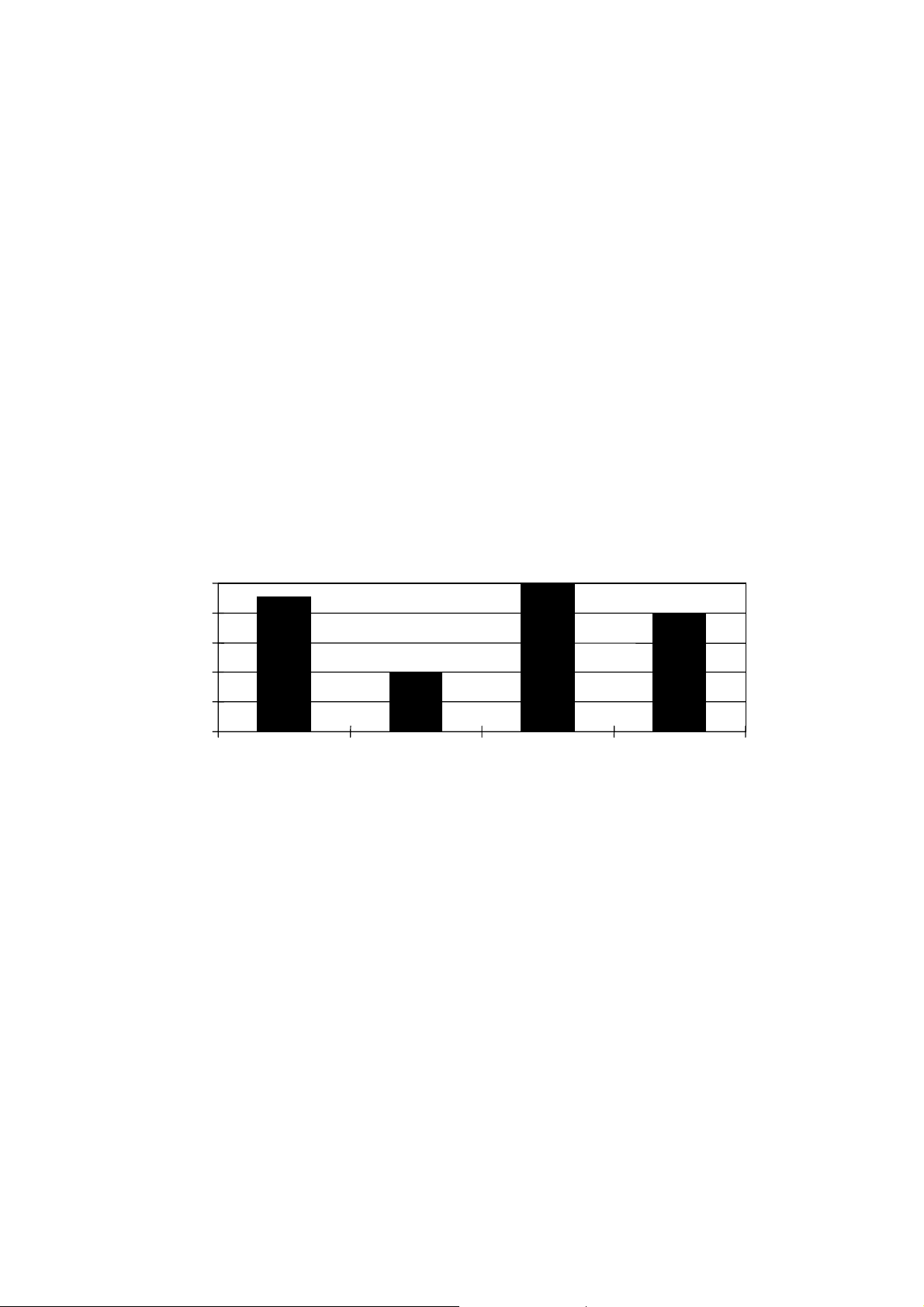
Competitor Information
According to our research, the lev el of the banding on this ma chine in comparison with
competitor models is as follows:
Related SP modes
Banding Level
5
4
3
2
1
Banding Level
0
(5: Best, 1: Worst)
AC6513 AC6010 CLC1150 X 1250
Laser copier
NA
Related Information
Size of Rollers
Hot roller/Pressure roller: 60mm diameter, 187 mm circumference
Drum: 90mm diameter, 283mm circumference
Troubleshooting
NA
8
15 May, 2001 Basic Tips for Cattleya 2
1-5. Jitter
Definition
Dark or light bands perpendicu lar t o the paper feed direction, as vibration in the machine is
transmitted to the laser writ ing area. The Interval between bands varies, however the
general location is usually fixed (e. g. 130mm from the trailing edge).
Specification
There is no specification available for jitter. It is extremely difficult to completely elim inat e
this symptom with current laser printing technology. Please refer to the image sample
section for the jit t e r level.
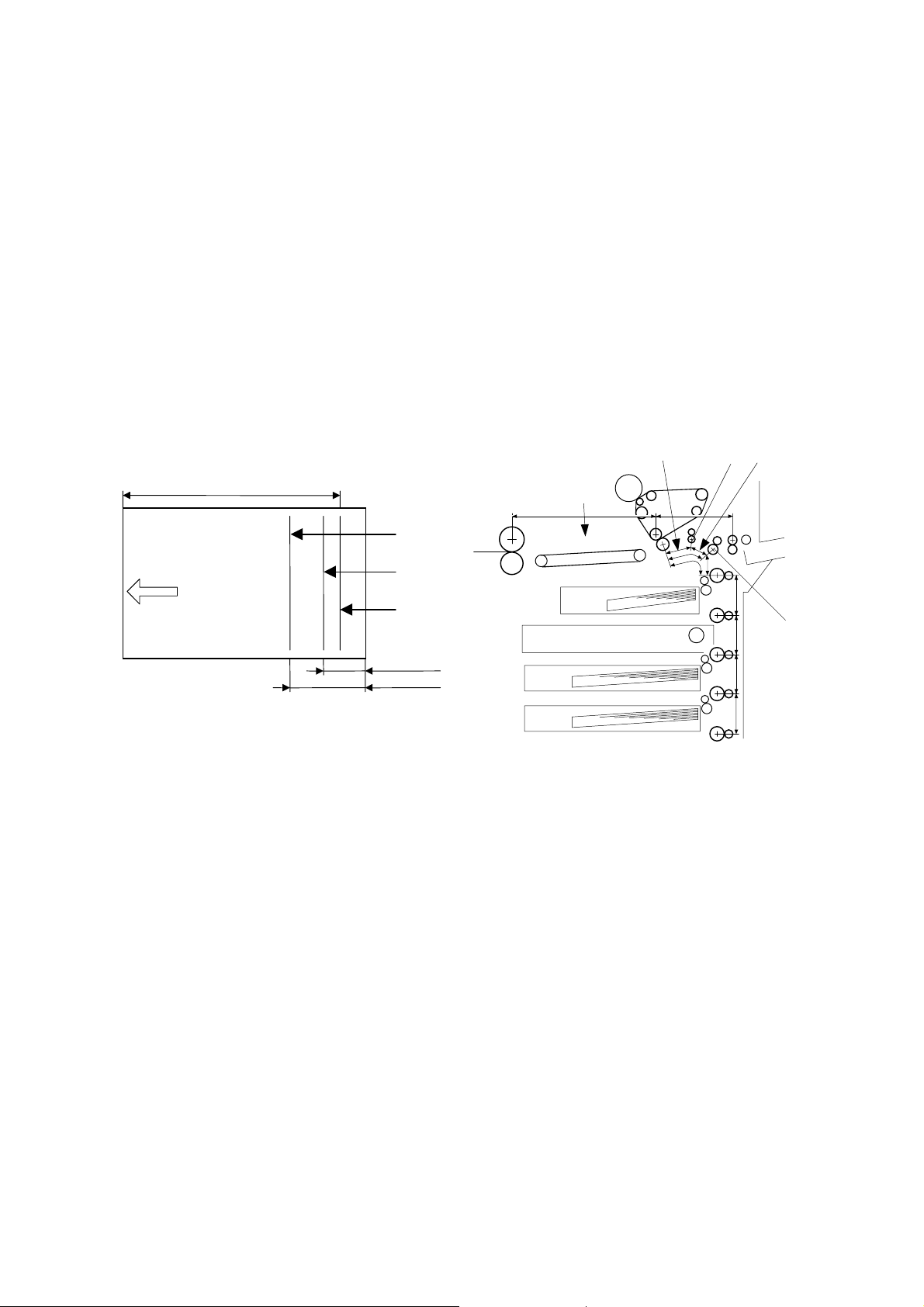
Jitter in Thick or Extra Thick paper modes
If jitter appears in Thick or Ext r a Thick paper modes at the posit ion shown in figure [A], [B]
and [C], please confirm the following:
75mm
360mm
A3/DLT
Approx. 360mm
[C]
[D]
Feed direction
[B]
[A]
Approx. 75mm
Approx. 135mm
1) Jitter [A]: Approx. 360 mm from the leading edge
• Possible cause: The leading edge does not enter the fusing nip [D] smoothly, and the
paper impacts on some surrounding area, causing it to feel shock.
• Check to see if the fusing entranc e area components are properly alligned, and if the
area is dirty at all.
2) Jitter [B]: Approx. 75 mm from the trailing edge
• Possible cause: The shock felt by the paper when the tra il in g edge leaves the
registration rollers [E].
• Try adjusting the following SP modes:
SP1-801-011 (Registrati on motor speed for thick paper)
SP1-801-012 (Registrati on motor speed for extra thick pap er)
*Default: – 0.2, value range: –5.0 to +5.0, step 0.1
3) Jitter [C]: Approx. 135 mm from the trailing edge
• Cause: The shock felt by the paper w hen t he t r ailing edge leaves the paper feed
rollers [F].
• Try adjusting the following SP modes:
SP1-801-005 (Paper feeding motor speed for thick paper)
SP1-801-008 (Paper feeding motor speed for extra thick paper)
*Default: –2.0, value range: –5.0 to +5.0, step 0.1
[E]
135mm
[F]
B023T023.WMF
9
15 May, 2001 Basic Tips for Cattleya 2
Competitor Information
N/A
References – Paper siz e
Paper inch mm Paper mm
Half Letter 5.5x8.5 134x208 A5 148x210
Letter 8.5x11 208x269 A4 210x297
Legal 8.5x14 208x343 B4 257x364
Ledger 11x17 269x416 A3 297x420
12x18 12x18 294x441 — —
13x19 13x19 318x465 A3 Wide 318x465
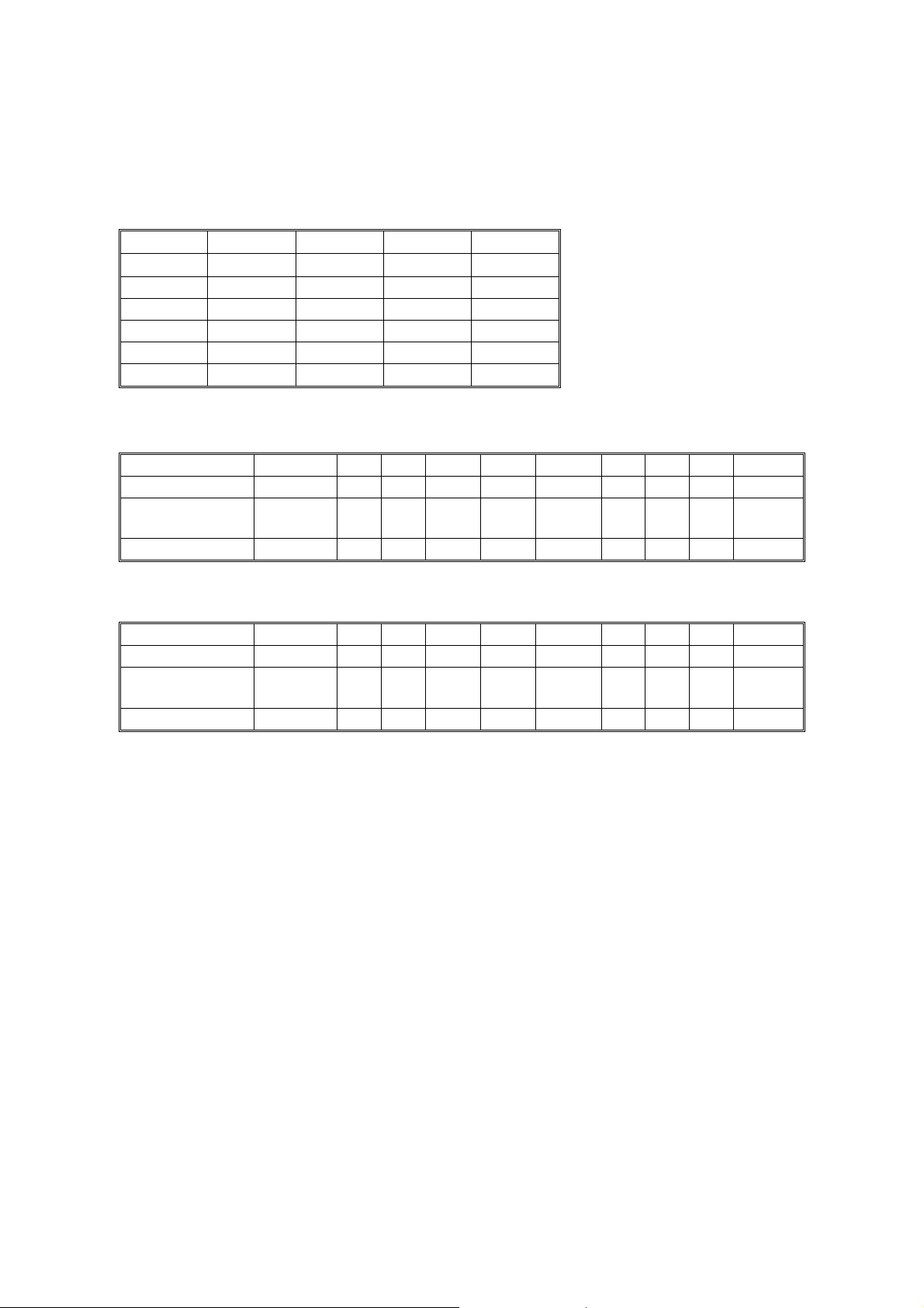
Length from leading edge for po ssible jitter S: Sideways, L: Lengthwise
HLT/LT S LT L DLT 12x18 13x19 A5/A4S B4 A4 L A3 S3 Wide
Fusing entrance — — 360 360 360 — 360 — 360 360
Registration
Roller 138 227 350 371 395 140 294 227 350 395
Relay Roller 73 162 295 306 330 75 229 162 285 330
Length from trailing edge for possible jitter S: Sideways, L: Lengthwise
HLT/LT S LT L DLT 12x18 13x19 A5/A4S B4 A4 L A3 S3 Wide
Fusing entrance — — 56 81 105 — 4 — 60 105
Registration
Roller 70 70 70 70 70 70 70 70 70 70
Relay Roller 135 135 135 135 135 135 135 135 135 135
10

15 May, 2001 Basic Tips for Cattleya 2
1-6. Hue / Density Consistency
Definition
Different hue bands appear in solid image areas perpendicular to the paper feed direction.
The possible cause is a shi ft in t he dot alignment or an unev en development roller speed.
Specification
No
specification
is available for hue change. In addition, this cannot be completely
eliminated with current laser printing technology. Please refer to the image
sample section for the hue change level.
Competitor Information
NA
Related SP modes
NA
Troubleshooting
NA
11
15 May, 2001 Basic Tips for Cattleya 2
1-7. Thick Paper Handling 1-7-1. Overview
Thick paper handling is one of the sales points of the Cattleya series. Thick Mode (carried
over from Cattleya1) has been enhanced, and Very Thick Mode has been newly added.
These modes are able to handle the vast majority of thick paper types, however in some
cases fine tuning of the fusing temperature may be required. Therefore, please read the
following carefully and t ake the appropriate act io ns as listed at each occasion.
1-7-2. At Installation
1. Refer to the below box and follow t he instructions if the customer in w hich the machine
is about to be installed uses t he l isted t ype of paper in the most frequ ent manner.
! The following papers hav e already been tested in Jap an and it was confirmed th at
the fine tuning is NOT neede d for the 3 types of paper:
- Neusiedler Colour Copy White 250g/m2
- Neusiedler Colour Copy White 200g/m2
- Hammermille Color Copy Cover 80lb (216g/m2)
! Regarding the Fedrigo ni 200g/m2, we strongly recommend to perform the “3-4.
Fine tuning #2” at the installation.
2. If not listed, a clear exp lanation to the customer is required on the different kind of
paper modes available for t hi s machine, and that they follow t his setting sequence
properly.
Paper Modes
Mode: G/m2: Lb. (Bond): Feeding Speed:
Normal 64 to 105 17 to 28 245 mm/sec
OHP — — 122.5mm/sec
Thick 105 to 157 28 to 42 122.5mm/sec
Very Thick 157 to 256 42 to 68 70mm/sec
1-7-3. At First Visit After Installation (Approx. 40kD)
1. When making a first visit to the customer’s site since instal lation (It is probably 40kD
since the installation for cleaning the fusing blade), check the condition of the parts
listed in the following table. If their condition i s similar to the pictures shown b elow , take
a necessary action that is mentione d in t he t able.
12
15 May, 2001 Basic Tips for Cattleya 2
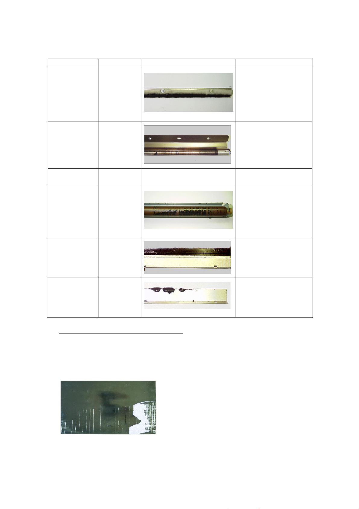
Part Name Part Number Conditions Action
Oil Supply Felt A2574171 If the condition is same
or comparable to the
picture on the left,
replace this part.
Pre-cleaning
Roller
Hot Roller AE010034 (no picture). Replace if damaged.
Cleaning Roller AE042044 Clean the part.
Hot roller blade AE 043031 Clean the part.
Scraper A2574213 Clean the part.
AE042049 Replace the roller if it is
noticeably dirtier than
the one shown in the
picture on the left.
3-2. With the exception of the pre-cleaning roller*, if you have the condit ion as shown in the
table above (even if one of the part s in t he t able gets dirty), reduce the fusi ng t emperature
according to the followin g procedure described as “FINE TU NIG #1”. This is because in
most of these cases are caused by t he over-fusing, also known as “hot offset”.
*As the pre-cleaning roller becomes dirty under the normal operating, this should not be
used to judge whether or not the fine-tu ned adjustment is needed.
Figure: Example of the Hot offset image
13

15 May, 2001 Basic Tips for Cattleya 2
3-3. Procedure – Fine Tuning #1
Set the fusing temperat ure as f ollows:
The Main firmware ver 1.082 or earlier:
SP1-105 - 002. Single side H ot Idling 195 " 190
005. Single side Hot OHP/Thick FC 180 " 168
006. Single side Hot OHP/Thick 1C 180 " 168
007. Single side Pressure Idl ing 160 " 155
010. Single side Press. OH P/ Thick FC 155 " 143
011. Single side Press. OH P/ Thick 1C 155 " 143
012. 2nd side Hot Idling 195 " 190
015. 2nd side Hot OHP/Thic k F C 180 " 168
016. 2nd side Hot OHP/Thic k 1 C 180 " 168
017. 2nd side Pressure Idling 160 " 155
020. 2nd side pressure OHP/Thick FC 155 " 143
021. 2nd side pressure OHP/Thick 1C 155 " 143
The Main firmware ver 1.09 or later:
SP1-105 - 002. Single side Hot I dling 195 " 190
022* Single side Hot Thick2 : FC 180 " 168
023* Single side Hot Thick2 : 1C 180 " 168
007. Single side Pressure Idl ing 160 " 155
024* Single side Pressure.Thick2: FC 155 " 143
025* Single side Pressure. Th ick2: 1C 155 " 143
012. 2nd side Hot Idling 195 " 190
026* 2nd side Hot Thick2.: FC 180 " 168
027* 2nd side Hot Thick2 : 1C 180 " 168
017 2nd side Pressure Idling 160 " 155
028* 2nd side pressure Thick2: FC 155 " 143
029* 2nd side pressure Thick2: 1C 155 " 143
*: Newly added SP modes from Ma in f irmware v1.09.
Note:
• Decreasing the fusing t emp erat ure will not damage the machi ne, t he only effect on copy
quality will be unev en image density and/or uneven glossiness.
• When using main firmware ver 1.082 or earlier, the above temperature adjustment will
affect not only Extra Thick Paper Mode (Thick 2) but also Thick Paper Mode (Thick 1) as
well.
• As this is only a guideline t o reducing hot offset, depending on the kind of paper, you may
need to reduce the temperature more tha n t he above figures. In which case, we sug gest
you do this by adjusting
SP 1-105-2, 5, 6, 12, 15, 16. (main ver 1.082 or earlier)
SP 1-105-2, 22, 23, 12, 26, 27 (main ver1.09 or later)
14

15 May, 2001 Basic Tips for Cattleya 2
3-4. Procedure – Fine Tuning #2
Hot/Pressure Rol l er Temperature Sett i ng for the Fedrigo ni 200g/m2 paper commonly
used in Italian market: Set the fusi ng temperature as follows :
The Main firmware ver 1.082 or earlier:
SP 1-105 - 002. Single side Hot I dling 195 " 180
005. Single side Hot OHP/Thick FC 180 " 165
006. Single side Hot OHP/Thick 1C 180 " 165
007. Single side Pressure Idl ing 160 " 155
010. Single side Press. OH P/ Thick FC 155 " 143
011. Single side Press. OH P/ Thick 1C 155 " 143
012. 2nd side Hot Idling 195 " 180
015. 2nd side Hot OHP/Thic k F C 180 " 165
016. 2nd side Hot OHP/Thic k 1 C 180 " 165
017. 2nd side Pressure Idling 160 " 155
020. 2nd side pressure OHP/Thick FC 155 " 143
021. 2nd side pressure OHP/Thick 1C 155 " 143
The Main firmware ver 1.09 or later:
SP 1-105 - 002. Single side Hot I dling 195 " 180
022. Single side Hot Th ick2: FC 180 " 165
023. Single side Hot Th ick2: 1C 180 " 165
007. Single side Pressure Idl ing 160 " 155
024. Single side Pressure.Thick2: FC 155 " 143
025. Single side Pressure. Thick2: 1C 155 " 143
012. 2nd side Hot Idling 195 " 180
026. 2nd side Hot Thick2.: FC 180 " 165
027. 2nd side Hot Thick2 : 1C 180 " 165
017. 2nd side Pressure Idling 160 " 155
028. 2nd side pressure Thick2: FC 155 " 143
029. 2nd side pressure Thick2: 1C 155 " 143
15

15 May, 2001 Basic Tips for Cattleya 2
2. Customized Maintenance Program (CMP) 2-1. Overview
The Standard Maintenance Program PM table in the Service M anual is designed to support a
wide spectrum of customers, including copy shops (Print for Pay ) , graphic design firms,
publishing companies a s well as general office environ me nt s . Alt hough this program is abl e t o
satisfy the needs of most of these customers, there are some high-demand prof essionals (e.g.
copy shops) who constantly require t he image quality to be t op level with the high-coverage
prints they make. This tends to increase the number of service calls.
To accommodate this, we wou ld li ke to o f fer the Customized Maintenance Program, which is
designed to consistently provide the high-demand customer with an image qualit y of Level B*
or higher (see the table below for definiti ons). The CMP basically reduces t he maintenance
interval in order to keep the mach ine in a better condition than it would be under the Standard
Maintenance Program. We have carefully chosen only those parts t hat have a major effect on
image quality and whose PM intervals could be reduced. This will allow for a reduction i n t he
rising service costs.
Although we have specified reduced intervals for certain parts, the CMP is a guideline for field
technicians. The actual time o f rep lac ement we leave to the technician's discretion.
Table: Definition of the Image quality lev e ls:
Rating Definition
Level A (Ideal) The image quality is equivalent to that at installation.
Level B (Excellent) Although not the same as at installation, still a very high level of image quality.
Level C (Good) Some high-demand professionals (copy shops) may not be 100% satisfied.
Level D (Fair) Most users would not be satisfied.
Level F (Poor) Servicing required.
Note: The CMP was created based on the results of a 1.5 PM running test using 3 production
units.
16
15 May, 2001 Basic Tips for Cattleya 2
2-2. Know the machine capability
We made the print samples by using 3 production units. These samples show how the mage
quality will be deteriorated during 1.5PM (120kD). Please see them carefully and know the
machine capability.
Note: You can see the big color shift on the print samples in the binders. These were caused
by the proto-type controller and its utility. So, please do not pay attention to the color
shift.
You can find three binders as a set. They were made under the following c onditions:
Binder Number
Thick paper
usage ratio
Maintenance
Cleaned the hot roller blade at 40kD only
#1 25%
during 120kD run, no other maintenance
was performed.
Cleaned the hot roller blade at 40kD only
#2 25%
during 120kD run, no other maintenance
was performed.
Cleaned the hot roller blade at 20kD only
#3 100%
during 60kD run, no other maintenance was
performed.
The following two items are the key to maintain the print quality in high level:
1.
Glossiness
(e.g. less streaks in paper feed direction and adequate glossiness)
2. Solid/halftone fill (e.g. less white streaks in paper feed direction, even and
smooth solid/halftone fill))
We used the five ranking (see the section 1) to evaluate the glossiness and
solid/halftone fill of the print samples:
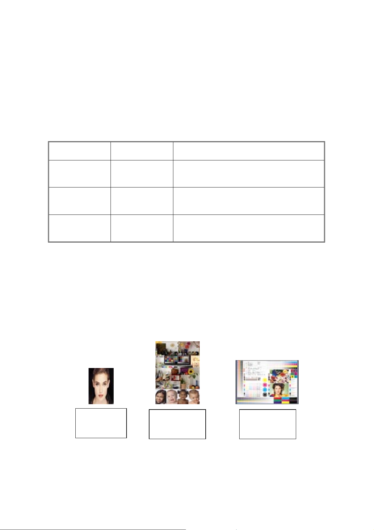
The print samples:
Woman with black
background, TIF
EFI Sample Many
Images, JPG
Graphic Test Image,
PDF
17

15 May, 2001 Basic Tips for Cattleya 2
Blue Solid, PPT
Side to Side,
Illustrator
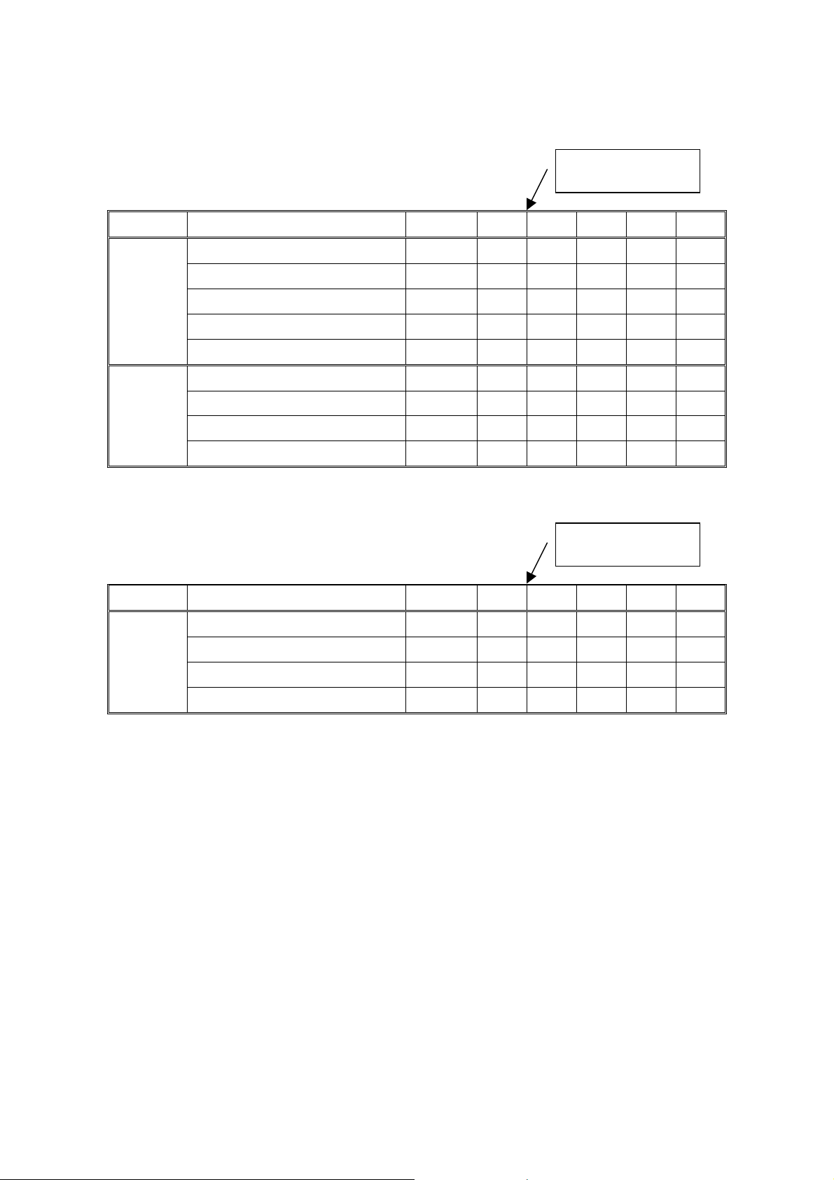
Glossiness for the #1 & #2 (25% Thic k paper usage)
Paper File / Original Installation 25kD 50kD 73kD 94kD 117kD
Woman with black back ground, TIF A C B C-D C-D D
EFI sample many images, JPG A A A A-B B B
Normal
Paper
Thick Paper
Graphic test image, PDF A A A B B C
Blue solid, PPT A B B C C-D D
C-4, COPY A A A C C-D D
EFI sample many images, JPG A B A-B C-D C-D D
Graphic test image, PDF A A A C C C
Blue solid, PPT A C B C C D
C-4, COPY
At 40kD, the hot roller
blade was cleaned.
C-4, COPY A B A-B B C C-D
At 20kD, the hot roller
Glossiness for the Machine #3 (100% Thick paper usage)
Paper File / Original Installation 13kD 23kD 33kD 42kD 52kD
EFI sample many images, JPG A A A B B B
Graphic test image, PDF A A A A-B A-B A-B
Thick Paper
Blue solid, PPT A A B B-C B B
C-4, COPY A A A B B B
blade was cleaned.
18
15 May, 2001 Basic Tips for Cattleya 2
At 40kD, the hot roller
Solid/Halftone fill for #1 and #2 (25% Thick paper usage)
Paper File / Original Installation 25kD 50kD 73kD 94kD 117kD
Woman with black back ground, TIF A A A A B B
EFI sample many images, JPG A A A C-D C C
Normal
Paper
Graphic test image, PDF A A A A B B
Blue solid, PPT A B B D D-E D-E
C-4, COPY A A A C C C
EFI sample many images, JPG A A A A B B
blade was cleaned.
Thick Paper
Solid/Halftone fill for #3 (100% Thick paper usag e)
Paper File / Original Installation 13kD 23kD 33kD 42kD 52kD
Thick Paper
Graphic test image, PDF A A A A B B
Blue solid, PPT A A A C C D
C-4, COPY A A A A B B
At 20kD, the hot roller
blade was cleaned.
EFI sample many images, JPG A A B B C C
Graphic test image, PDF A A B B C C
Blue solid, PPT A A-B B B-C C D
C-4, COPY A A B B C C
19
15 May, 2001 Basic Tips for Cattleya 2
2-3. How the CMP works
Glossiness
To maintain the image qual it y Level B or higher, we recommend the following maintenance
program:
Description Part # SMP CMP
Hot Roller AE010034 80kD Replacement 40kD Replacement
Oil Supply Pad A25 741 71 80kD Replacement 40kD Replacement
Cleaning Roller AE042044 80kD Cleaning 40kD Cleaning
Scraper 80kD Cleaning 40kD Cleaning
Hot Roller Blade AE043012 40kD Cleaning
80kD Replacement
Pressure Roller Blade A2574187 (220V only) 320kD Replacement 160kD Replacement
Pre-cleaning Roller AE042049 80kD Replacement 40kD Replacement
20kD Cleaning
40kD Replacement
SMP: Standard Maintenance Program
CMP: Customized Maintenance Program
Solid / Halftone Fill
To maintain the image q uality Level B or higher for the pot ion of the Solid / Halftone fill, we
recommend the following maintenance program:
Description Part # SMP CMP
Developer -K — 60kD Replacement by
PM counter
Developer- C, M, Y — 48kD Replacement for
each color
PCC Wire AD020084 160kD Replacement 80kD Replacement
Drum Cleaning Blade AD041050 100kD Replacement 40kD Replacement
Drum Lubricant Bar A2573607 80kD Replacement 40kD Replacement
34kD replacement by
PM counter
27kD replacement
for each color
Drum Cleaning Brush AD042043 100kD Replacement 40kD Replacement
Drum B0239510 80kD Replacement 40kD Replacemen t
Drum Unit — 80kD Cleaning 40kD Cleaning
Charge Corona Wire AD020086 80kD Replacement 40kD Replacement
Charge Corona Grid AD020085 100kD Replacement 40kD Replacement
Belt Cleaning Unit — 80kD Cleaning 40kD Cleanin g
ITB Cleaning Blade A2576350 200kD Replacement 100kD Replacement
ITB Lubricant Bar B0236350 200kD Replacement 100kD Replacement
ITB Lubricant Brush B0236358 200kD Replacement 100kD Replacement
Transfer Belt B0236050 80kD Replacement 40kD Repla cement
20

15 May, 2001 Basic Tips for Cattleya 2
2-4. Procedure
1. Get the following information:
- How the print-out w ill be used at the custo mer site
(for sell, for internal distribution, for graphic d esi gn check).
- Customer’s dema nd
- Thick paper usage ratio
2. Discuss with the customer about the machine capabil it y and suggest the CMP if you think
that this program is needed the cust omer based on the information above.
3. Find the SMP / CMP ta ble in the Appendix D.
You can use this table whether the S M P or t he CMP will be performed.
Note: The CMP in the Appendix D is a guide line for the customer whose application is approx.
75% or higher thick paper usage ratio and h igh d emand on the image quality with the
high-coverage prints they make.
Although we have specified reduced intervals f or cert ain parts, the CMP is a guide line for
field technicians. The actua l ti me of rep lacement we leave to the technician's discretion.
21

15 May, 2001 Basic Tips for Cattleya 2
Appendix A: Test patterns
Max ID: ACC Pattern
Banding: SP5-955-6 Solid 55 (K, C, M, Y, R, G, B, P)
Jitter: SP5-955- 7, 1 dot 2x2, 180
Unevenness in Half tone: SP5-955-7, 1 dot 2x2, 128
Hue change (mail scan): SP5-955-6, Solid 110 (Purple, Green)
Color shift (sub scan): SP4-417-8 (YMCK 16 gradation)
Line alignment: SP5-955-14 Grid
Note: The test patterns for the banding, the jitter, the unevenness in the half tone,
and the color shift, enhance those symptom to make the troubleshooting
easily. And, the level of the symptom is way wroth compare to the symptom
on the printing under the normal operation. This is because the dither of the
test images are different from the dither on the usual copy./print mode.
1

15 May, 2001 Basic Tips for Cattleya 2
Appendix B: SP Modes
SP Mode Types
The SP modes of this copier are divided into the following eight groups:
Screen Name Group
Feed Paper feed/transport/fusing
Drum Drum unit
Process Process control
Scanner Scanner unit
Mode Operating mode/system
Periphs Peripherals
Log Logged data
Special Mode Others (special mode s)
Service Program Mode tables
NOTE:
1) In the Function/[Setting] column:
• The related pop-up screen and SP7 function (if any) are in parenthesis
after the function description,
• Comments are in italics.
• The “Setting” range is in brackets and the default “Setting” value is in
bold.
2) Clearing the RAM resets SP and UP values to their defaults. It does not
affect the serial number and main counter value, however.
3) DFU Designer or Factory Use only. Do not change these values.
4) USM This SP is ignored unless the user selects ‘Service Mode’ in UP
mode.
5) IAJ See “Replacement and Adjustment - Copy Image Area
Adjustments” for details.
6) RA See “Replacement and Adjustment” for details.
1
15 May, 2001 Basic Tips for Cattleya 2
SP1-XXX (Feed)
1
001
002
003
105
Mode Number/Name Function / [Setting]
Leading Edge Registration
1 Normal paper
2OHP
3 Thick paper 1
4 Thick paper 2
5 Duplex
6 Second sheet, Half speed
7 Second sheet, 1/3rd speed
Side-to-Side Registration
1 By-pass
2Tray 1
3Tray 2
4Tray 3
5Tray 4
6 2nd side
7LCT
Paper Feed Timing
1 Normal paper, by-pass
2 Tray paper feed
3 By-pass OHP
4 By-pass: Thick paper 1
5 2nd side
6 By-pass: Thick paper 2
7 Tray: Thick paper 1
8 Tray: Thick paper 2
By-pass Up Time010
Oil End Sensor101
Fusing Control104
Hot/Pressure Roller Temperature Setting (Screen B)
This SP sets the temperature of the hot and pressure rollers in various modes.
1 Single side: Hot: Reload
2 Single side: Hot: Idling
Single side: Hot: Normal
3
paper: FC
4 Single side: Hot: Normal
paper : 1C
5 Single side: Hot:
OHP/Thick paper: FC
Adjusts the leading edge registration by changing the
timing of the registration clutch. (Screen A, SP7-903)
[+7 to –7 / 0.0 / 0.1 mm/step] IAJ
Specification: 4 ± 1 mm
Thick paper 1 is listed as Thk on the screen.
Thick paper 2 is listed as Super Thk.
Adjusts the side-to-side registration by changing the
starting position for the laser’s main scan. (Screen A,
SP1-236)
[+9 to –9 / 0.0 / 0.1 mm/step] IAJ
Specification: 1.5 ± 0.5 mm. < 4 mm total
[ 5.0]
[ 5.0]
[ 3.0]
[ 1.5]
[ 5.0]
[–3.0]
[ 1.5]
[–3.0]
Not used.
NOTE: This SP is displayed and data can be input.
Turns the oil end sensor ON or OFF. (SP9-703)
[1 = ON, 0 = OFF]
Selects the fusing temperature control mode.
[1 = ON/OFF control, 0 = Phase control]
Phase control should be selected only if the user has a
problem with the fluorescent lamps flickering. The main
switch must be turned off and on when this setting is
changed.
[100 to 200 / 185 / 1°C/step]
Once the copier reaches this temperature, the ready light
comes on and copies can be made. The temperature
continues to increase until the ready state is reached.
[100 to 200 / 195 / 1°C/step]
Idling starts at 170
50
[100 to 200 / 180 / 1°C/step]
[100 to 200 / 170 / 1°C/step]
[100 to 200 / 180 / 1°C/step]
Adjusts the amount of paper buckle by changing
the timing of the relay clutch. A positive setting
creates more buckling.
(Screen A, SP7-903)
[+9 to –9 / 0.1 mm/step] +7 to –5 for by-pass:
thick paper
However, this function is not available.
C. If the temperature is higher than
°
C when the power is turned on, idling is not executed
°
2

15 May, 2001 Basic Tips for Cattleya 2
1
105
Mode Number/Name Function / [Setting]
6 Single side: Hot:
[100 to 200 / 180 / 1°C/step]
OHP/Thick paper: 1C
7 Single side: Pressure:
[100 to 200 / 160 / 1°C/step]
Idling
Single side: Pressure:
8
[100 to 200 / 155 / 1°C/step]
Normal paper: FC
9 Single side: Pressure:
[100 to 200 / 145 / 1°C/step]
Normal paper: 1C
10 Single side: Pressure:
[100 to 200 / 155 / 1°C/step]
OHP/Thick paper: FC
11 Single side: Pressure:
OHP/Thick paper: 1C
12 2nd side: Hot: Idling
2nd side: Hot: Normal
13
[100 to 200 / 195 / 1°C/step]
[100 to 200 / 180 / 1°C/step]
paper: FC
14 2nd side: Hot: Normal
[100 to 200 / 170 / 1°C/step]
paper: 1C
15 2nd side: Hot: OHP/Thick
[100 to 200 / 180 / 1°C/step]
paper: FC
16 2nd side: Hot: OHP/Thick
paper: 1C
17 2nd side: Pressure: Idling
2nd side: Pressure: Normal
18
[100 to 200 / 160 / 1°C/step]
[100 to 200 / 155 / 1°C/step]
paper: FC
19 2nd side: Pressure: Normal
[100 to 200 / 145 / 1°C/step]
paper: 1C
20 2nd side: Pressure:
[100 to 200 / 155 / 1°C/step]
OHP/Thick paper: FC
21 2nd side: Pressure:
OHP/Thick paper: 1C
22
Single side Hot Thick 2: FC
23
Single side Hot Thick 2: 1C
24
Single side Pressure: Thick
[100 to 200 / 180 / 1°C/step]
[100 to 200 / 180 / 1°C/step]
[100 to 200 / 155 / 1°C/step]
2: FC
25
Single side Pressure, Thick
2: 1C
26
27
28
29 2
nd
2
side Hot Idling
nd
2
side Hot Thick 2: FC
nd
2
side Hot Thick 2: 1C
nd
side Pressure Thick 2:
[100 to 200 / 155 / 1°C/step]
[100 to 200 / 180 / 1°C/step]
[100 to 200 / 180 / 1°C/step]
[100 to 200 / 155 / 1°C/step]
[100 to 200 / 155 / 1°C/step]
1C
Fusing Temperature Display
106
1 Pressure roller Displays the temperature of the pressure roller.
2 Hot roller Displays the temperature of the hot roller.
108 Fusing Unit Set Disables fusing unit set detection. Keep at 0 for normal
operation.
[0 = Detect, 1 = Do not detect]
- Procedure Turn off the main switch.
Remove the fusing unit.
Keep the front door open and turn on the main switch.
Access the SP mode and set the data to 1.
Close the front cover.
Fusing Nip Band Check109
Use to check the width of the fusing nip band. RA
3

15 May, 2001 Basic Tips for Cattleya 2
1
112
801
901
Mode Number/Name Function / [Setting]
Fusing Temperature Correction for Environment Temperature
1 High temperature
2 Low temperature
Motor Speed Adjustment
1 Fusing motor: Normal
speed
Paper feed motor: Normal
2
speed
3 Drum motor: Normal speed
4 Fusing motor: Half speed
5 Paper feed motor: Half
speed
6 Drum motor: Half speed
7 Fusing motor: 1/3rd speed
8 Paper feed motor: 1/3rd
speed
9 Drum motor: 1/3rd speed
10 Registration motor: Normal
speed
11 Registration motor: Half
speed
12 Registration motor: 1/3rd
speed
20 New motor/Old motor
Duplex Unit Side/End Fence Adjustment
1 Side fence Adjusts the duplex side fence stop position.
2 End fence Adjusts the duplex end fence stop position.
DFU [0°°°°C]
DFU [5°°°°C]
DFU [–5.0% to 5.0% / 0.0% / 0.1%/step]
DFU [–5.0% to 5.0% / 0.1% / 0.1%/step]
DFU [–3.0% to 3.0% / 0.0% / 0.1%/step]
DFU [–5.0% to 5.0% / 0.2% / 0.1%/step]
DFU [–5.0% to 5.0% / –2.0% / 0.1%/step]
DFU [–3.0% to 3.0% / 0.2% / 0.1%/step]
DFU [–5.0% to 5.0% / 0.2% / 0.1%/step]
DFU [–5.0% to 5.0% / –0.2% / 0.1%/step]
DFU [–3.0% to 3.0% / 0.2% / 0.1%/step]
DFU [–5.0% to 5.0% / 0.0% / 0.1%/step]
DFU [–5.0% to 5.0% / –0.2% / 0.1%/step]
DFU [0 to 1 / 0 / ]
1: New motor
0: Old motor
[–5.0 to 5.0 mm / 0 / 0.1 mm/step]
[–5.0 to 5.0 mm / 0 / 0.1 mm/step]
4

15 May, 2001 Basic Tips for Cattleya 2
SP2-XXX (Drum)
2
MChgCrrnt
10
1 MChgCrrnt EnvLmt [g/m3]
2
3
5
6
MchgFanONTime
11
1 Mchg FanONTime EnvLmt
2 MchgFanONTime [min]
3 MChgFanONTime [min]:
Sub-scan/Main-scan margin adjustment
101
1
2 Sub-scan: Leading edge:
3 Sub-scan: Leading edge:
4 Sub-scan: Leading edge:
5 Sub-scan: Trailing edge:
6
7 Sub-scan: Trailing edge :
8 Sub-scan: Trailing edge:
9 Main-scan: Leading edge Adjust leading margin. (operator side). (Screen C, SP9-
10 Main-scan: Trailing edge Adjusts the trailing margin. (Screen C, SP9-703)
11 Sub-scan: Auto 2nd side:
Fax Print Gamma Parameter111
000 Fax Print Gamma
Main scan magnification adjustment
112
1 Copy mode DFU [0] (Screen D, SP9-703)
2 Print mode Adjusts the magnification in the main scan direction for
Sub-scan magnification adjustment
113
1 Copy mode Adjusts the magnification in the sub-scan direction for
2 Print mode
Mode Number Function / [Setting]
MChgCrrnt [µA]: EnvHigh
MChgCrrnt [µA]
MChgCrrnt [µA]: Half
MChgCrrnt [µA]: 1/3rd
3
]
[g/m
EnvLow
Sub-scan: Leading edge:
Normal
Thick 1
Thick 2
OHP
Normal
Sub-scan: Trailing edge:
Thick 1
Thick 2
OHP
Trailing edge of 1st side
Parameter
DFU [0.6 to 50.0 / 11.0 / 0.1]
DFU [400 to 850 / 700 / 1.0]
DFU [400 to 850 / 560 / 1.0]
DFU [400 to 850 / 0 / 1.0]
DFU [0.6 to 50.0 / 4.3 / 0.1]
DFU [0.0 to 900.0 / 0.5 / 0.1]
DFU [0.0 to 900.0 / 20.0 / 0.1]
Adjusts the margin along the front edge. (Screen C, SP9-
703)
[–4.0 to 4.0 mm / 0 / 0.1 mm/step]
Adjusts the margin along the back edge. (Screen C, SP9-
703)
[–3.0 to 10.0 mm / 0 / 0.1 mm/step]
703)
[–2.0 to 5.0 mm / 0 / 0.1 mm/step]
[–2.0 to 5.0 mm / 0 / 0.1 mm/step]
Adjusts the trailing margin for the first side of duplex
copies. (Screen C, SP9-703)
[–3.0 to 10 mm / 0 / 0.1 mm/step]
Japan Only [0 to 255 / 192 / 1 per step]
printer mode. (Screen D, SP9-703)
[–1.0% to +1.0% / 0 / 0.1/step]
copy mode. (Screen D, SP9-703)
[–1.0% to +1.0% / 0 / 0.1/step]
Adjusts the magnification in the sub-scan direction for
printer mode. (Screen D, SP9-703)
[–1.0% to +1.0% / 0 / 0.1/step]
The screen displays “FsynchMagAdj PRINTER”.
5

15 May, 2001 Basic Tips for Cattleya 2
2
Forced toner supply positioning
207
1K
2C
3M
4Y
Forced toner supply cycle count
208
1K
2C
3M
4Y
5 Toner supply ratio: Fixed
6 Toner supply ratio: Fixed
7 Toner supply ratio: Fixed
8 Toner supply ratio: Fixed
9 Toner supply method Selects the toner supply method.
Developer initialization
225
1Exe: K
2Exe: C
3Exe: M
4Exe: Y
5Exe: All
6Exe: CMY
ITB bias adjustment
301
1 4C: 1st color
2 4C: 2nd color
3 4C: 3rd color
4 4C: 4th color
5 2C: 1st color
6 2C: 2nd color
7 3C: 1st color
8 3C: 2nd color
9 3C: 3rd color
10 1C : 1st color
11 Non-image areas
Mode Number Function / [Setting]
mode: K
mode: C
mode: M
mode: Y
Moves the selected development unit to the development
position and forces toner to be supplied in according to
the setting in SP2-208.
Press ON key to start after selecting the color.
Sets the number of forced toner supply cycles.
[1 to 50 / 10 / cycles]
The toner supply clutch turns on and off for 1 second.
This cycle repeats a number of times equal to the value
selected. (Approximately 0.5g of toner is supplied each
cycle. Therefor, about 5g of toner is supplied using the
default setting. This increases the toner density by about
0.7wt%.)
Sets the toner supply ratio for each color in fixed mode.
[0% to 100% / 5% / 1%/step]
0 = Fixed supply
1 = Proportional control supply (with TD sensor output)
2 = Fuzzy control supply
Initializes the developer and performs a forced self check
on the selected colors. Press the Execution key to start.
The results are displayed on the operation panel.
(Screen E)
0 = failure, 1 = success
Initial Vref check
The execution sequence is: Aging
Forced process control self-check.
DFU Adjusts the image transfer belt bias in standard
speed mode for each transfer process (1C - 4C) and color
mode selected.
[5 to 50 µA / 22 µµµµA / 1 µA/step]
[5 to 50 µA / 25 µµµµA / 1 µA/step]
[5 to 50 µA / 27 µµµµA / 1 µA/step]
[5 to 50 µA / 29 µµµµA / 1 µA/step]
[5 to 50 µA / 22 µµµµA / 1 µA/step]
[5 to 50 µA / 25 µµµµA / 1 µA/step]
[5 to 50 µA / 22 µµµµA / 1 µA/step]
[5 to 50 µA / 25 µµµµA / 1 µA/step]
[5 to 50 µA / 27 µµµµA / 1 µA/step]
[5 to 50 µA / 22 µµµµA / 1 µA/step]
DFU Adjusts the image transfer belt bias for the non-
image areas.
[5 to 50 µA / 6 µµµµA / 1 µA/step]
→
→
6

15 May, 2001 Basic Tips for Cattleya 2
2
301
Mode Number Function / [Setting]
12 Half-speed
24 VD Bias correction ON/OFF
25 4C : 2nd side : 1st color
26 4C : 2nd side : 2nd color
27 4C : 2nd side : 3rd color
28 4C : 2nd side : 4th color
29 2C : 2nd side : 1st color
30 2C : 2nd side : 2nd color
31 3C : 2nd side : 1st color
32 3C : 2nd side : 2nd color
33 3C : 2nd side : 3rd color
34 1C : 2nd side : 1st color
DFU Adjusts the image transfer belt bias for OHP/Thick
paper modes (Half speed). Before transferring to the
paper in these modes, the developed image on the
transfer belt passes the drum to synchronize the
registration.
[5 to 50 µA / 6 µµµµA / 1 µA /step]
DFU Sets the correction mode to ON or OFF. If ON, the
transfer belt bias for image area is corrected by V
(process control potential table).
[0 = ON, 1 = OFF]
DFU Adjusts the image transfer belt bias for the second
side copy in duplex mode for each transfer process (1C 4C) and color mode selected.
[5 to 50 µA / 22 µµµµA / 1 µA/step]
[5 to 50 µA / 25 µµµµA / 1 µA/step]
[5 to 50 µA / 27 µµµµA / 1 µA/step]
[5 to 50 µA / 29 µµµµA / 1 µA/step]
[5 to 50 µA / 22 µµµµA / 1 µA/step]
[5 to 50 µA / 25 µµµµA / 1 µA/step]
[5 to 50 µA / 22 µµµµA / 1 µA/step]
[5 to 50 µA / 25 µµµµA / 1 µA/step]
[5 to 50 µA / 27 µµµµA / 1 µA/step]
[5 to 50 µA / 22 µµµµA / 1 µA/step]
D
35 Lubricant brush 1
36 Lubricant brush 2
37 1/3rd Speed
40 V
PTR bias - Humidity range threshold
302
D
correction coefficient
1 Threshold 1
2 Threshold 2
3 Threshold 3
4 Threshold 4
These appear on the operation panel in the following
format, “1st 4C-mode NrmlBack”.
DFU Adjusts the image transfer belt bias during lubricant
brush cleaning mode.
[5 to 50 µA / 6 µA / 1 µA/step]
These appear as “Q1_Brush CLN1” and “Q1_Brush
CLN2”
DFU [5.0 to 50.0 µA / 5.0 µA / 1 µA/step ]
DFU [0 to 2.5 / 1.0 / 0.01/step]
DFU
Changes the thresholds for absolute humidity adjustment.
TH1 TH2 TH3 TH4
||||
Environment: LL L Normal H
HH
LL: Very low humidity [0.6 to 50 g/m
L : Low humidity [0.6 to 50 g/m3 / 11.3 g/m3/ 0.1]
H : High humidity [0.6 to 50 g/m3 / 18.0 g/m3/ 0.1]
HH: Very high humidity [0.6 to 50 g/m3 / 24.0 g/m3/ 0.1]
These appear as “EnvLmt [0]” through “EnvLmt [3].”
3
/ 4.3 g/m3 / 0.1]
7

15 May, 2001 Basic Tips for Cattleya 2
2
PTR bias adjustment
310
1 Humidity range set-up Specifies which humidity range is used for paper transfer
SP2-310-2 to SP2-310-29 adjust the PTR bias for the type of paper and the copy mode.
(Screen F, SP9-703)
2 Image area: Normal: 1C
3 Image area: Normal: 2C
4 Image area: Normal: 3C
5 Image area: Normal: 4C
6 Image area: Thick 1: 1C
7 Image area: Thick 1: 2C
8 Image area: Thick 1: 3C
9 Image area: Thick 1: 4C
10 Image area: OHP:1C
11 Image area: OHP:2C
12 Image area: OHP:3C
13 Image area: OHP:4C
14 Image area: Thick 2: 1C
15 Image area: Thick 2: 2C
16 Image area: Thick 2: 3C
17 Image area: Thick 2: 4C
18 Image area: Normal: 2nd
19 Image area: Normal: 2nd
20 Image area: Normal: 2nd
21 Image area: Normal: 2nd
22 Image area: Thick 1: 2nd
23 Image area: Thick 1: 2nd
24 Image area: Thick 1: 2nd
25 Image area: Thick 1: 2nd
26 Image area: Thick 2: 2nd
27 Image area: Thick 2: 2nd
28 Image area: Thick 2: 2nd
29 Image area: Thick 2: 2nd
Mode Number Function / [Setting]
bias. Change the value only if the humidity sensor fails.
0 = fixed humidity range (normal condition)
1 = changed by humidity sensor
2 = fixed humidity range (LL)
3 = fixed humidity range (L)
4 = fixed humidity range (H)
5 = fixed humidity range (HH)
The screen displays “EnvChoise”.
DFU [5 to 100 µA / 40 µµµµA / 1 µA /step]
DFU [5 to 100 µA / 47 µµµµA / 1 µA /step]
DFU [5 to 100 µA / 55 µµµµA / 1 µA /step]
DFU [5 to 100 µA / 16 µµµµA / 1 µA /step]
DFU [5 to 100 µA / 18 µµµµA / 1 µA /step]
DFU [5 to 100 µA / 24 µµµµA / 1 µA /step]
DFU [5 to 100 µA / 30 µµµµA / 1 µA /step]
DFU [5 to 100 µA / 36 µµµµA / 1 µA /step]
DFU [5 to 100 µA / 12 µµµµA / 1 µA /step]
DFU [5 to 100 µA / 14 µµµµA / 1 µA /step]
DFU [5 to 100 µA / 16 µµµµA / 1 µA /step]
DFU [5 to 100 µA / 40 µµµµA / 1 µA /step]
side: 1C
DFU [5 to 100 µA / 42 µµµµA / 1 µA /step]
side: 2C
DFU [5 to 100 µA / 45 µµµµA / 1 µA /step]
side: 3C
side: 4C
DFU [5 to 100 µA / 16 µµµµA / 1 µA /step]
side: 1C
DFU [5 to 100 µA / 19 µµµµA / 1 µA /step]
side: 2C
DFU [5 to 100 µA / 22 µµµµA / 1 µA /step]
side: 3C
side: 4C
DFU [5 to 100 µA / 12 µµµµA / 1 µA /step]
side: 1C
DFU [5 to 100 µA / 14 µµµµA / 1 µA /step]
side: 2C
DFU [5 to 100 µA / 16 µµµµA / 1 µA /step]
side: 3C
side: 4C
8

15 May, 2001 Basic Tips for Cattleya 2
2
SP2-310-30 to SP2-310-37 adjust the PTR bias used for the ID sensor pattern. (Screen F,
310
SP9-703)
30 ID pattern: Normal: 1C
31 ID pattern: Normal: 2C
32 ID pattern: Normal: 3C
33 ID pattern: Normal: 4C
34 ID pattern: All others: 1C
35 ID pattern: All others: 2C
36 ID pattern: All others: 3C
37 ID pattern: All others: 4C
38 Lubricant brush (Belt
311 1 Forced belt cleaning Lubricates the image transfer roller. Press the ON key to
PTR bias: Paper size correction
313
1 Normal: LT (S) or larger
2 Normal: B4 or larger
3 Normal: A5 (L) or larger
4 Normal: Less than A5 (L)
5 Thick 1: LT (S) or larger
6 Thick 1: B4 or larger
7 Thick 1: A5 (L) or larger
8 Thick 1: Less than A5 (L)
9 OHP:LT (S) or larger
10 OHP:B4 or larger
11 OHP:A5 (L) or larger
12 OHP: Less than A5 (L)
13 Thick 2: LT (S) or larger
14 Thick 2: B4 or larger
15 Thick 2: A5 (L) or larger
16 Thick 2: Less than A5 (L)
PTR bias: Leading edge correction
314
DFU Corrects the PTR bias for the paper leading edge area for the type of paper and copy
mode. The paper transfer belt bias times the percentage selected in this SP mode is applied to
the bias roller. (SP9-703)
1 Normal: 1C
2 Normal: 2C
3 Normal: 3C
4 Normal: 4C
5 Thick 1: 1C
6 Thick 1: 2C
7 Thick 1: 3C
8 Thick 1: 4C
9OHP: 1C
10 OHP: 2C
11 OHP: 3C
12 OHP: 4C
13 Thick 2: 1C
14 Thick 2: 2C
15 Thick 2: 3C
16 Thick 2: 4C
Mode Number Function / [Setting]
DFU [5 to 100 µA / 20 µµµµA / 1 µA /step]
DFU [5 to 100 µA / 50 µµµµA / 1 µA /step]
30 – 33 labeled as “P:Nrml”
DFU [5 to 100 µA / 12 µµµµA / 1 µA /step]
DFU [5 to 100 µA / 14 µµµµA / 1 µA /step]
34 – 37 labeled as “P:ElseNrml”
DFU Adjusts the paper transfer roller bias during lubricant
cleaning mode)
brush cleaning. (Screen F, SP9-703)
[5 to 100 µA / 35 µµµµA / 1 µA /step]
start.
This mode may help alleviate partial blank areas or
insufficient roller cleaning.
DFU Corrects the PTR bias for the paper type and size.
The paper transfer roller bias times the percentage
selected in this SP mode is applied to the bias roller.
(S = sideways, L = lengthwise)
[50 to 500% / 100% / 1%/step] (except for SP2-313-008)
[50 to 500% / 200% / 1%/step] (SP2-313-008)
[50 to 200% / 110% / 1%/step]
[50 to 200% / 79% / 1%/step]
[50 to 200% / 100% / 1%/step]
9

15 May, 2001 Basic Tips for Cattleya 2
2
314
315
316
17 Normal: 2nd side: 1C
18 Normal: 2nd side: 2C
19 Normal: 2nd side: 3C
20 Normal: 2nd side: 4C
21 Thick 1: 2nd side: 1C
22 Thick 1: 2nd side: 2C
23 Thick 1: 2nd side: 3C
24 Thick 1: 2nd side: 4C
25 Thick 2: 2nd side: 1C
26 Thick 2: 2nd side: 2C
27 Thick 2: 2nd side: 3C
28 Thick 2: 2nd side: 4C
PTR bias: Trailing edge correction
DFU Corrects the PTR bias for the paper trailing edge based on the type of paper and copy
mode. The paper transfer roller bias times the percentage selected in this SP mode is applied
to the bias roller. (SP9-703)
1 Normal: 1C
2 Normal: 2C
3 Normal: 3C
4 Normal: 4C
5 Thick 1: 1C
6 Thick 1: 2C
7 Thick 1: 3C
8 Thick 1: 4C
9OHP: 1C
10 OHP: 2C
11 OHP: 3C
12 OHP: 4C
13 Thick 2: 1C
14 Thick 2: 2C
15 Thick 2: 3C
16 Thick 2: 4C
17 Normal: 2nd side: 1C
18 Normal: 2nd side: 2C
19 Normal: 2nd side: 3C
20 Normal: 2nd side: 4C
21 Thick 1: 2nd side: 1C
22 Thick 1: 2nd side: 2C
23 Thick 1: 2nd side: 3C
24 Thick 1: 2nd side: 4C
25 Thick 2: 2nd side: 1C
26 Thick 2: 2nd side: 2C
27 Thick 2: 2nd side: 3C
28 Thick 2: 2nd side: 4C
PTR bias: Humidity correction
DFU Corrects the PTR bias for the humidity condition based on the type of paper and copy
mode. The paper transfer belt bias times the percentage selected in this SP mode is applied.
LL = Very low humidity, L = Low humidity, H = High humidity, HH = Very high humidity
1 LL: Normal : 1C
2 LL: Normal: 4C
3 L: Normal: 1C
4 L: Normal: 4C
5 H: Normal: 1C
6 H: Normal: 4C
Mode Number Function / [Setting]
[50 to 200% / 100% / 1%/step]
[50 to 200% / 68% / 1%/step]
[50 to 200% / 100% / 1%/step]
[50 to 200% / 100% / 1%/step]
[50 to 200% / 79% / 1%/step]
[50 to 200% / 100% / 1%/step]
[50 to 200% / 68% / 1%/step]
[50 to 200% / 100% / 1%/step]
[50 to 200% / 100% / 1%/step]
[50 to 200% / 120% / 1%/step]
[50 to 200% / 100% / 1%/step]
10

15 May, 2001 Basic Tips for Cattleya 2
2
316
Mode Number Function / [Setting]
7 HH: Normal: 1C
8 HH: Normal: 4C
9 LL: Thick 1: 1C
10 LL: Thick 1: 4C
11 L: Thick 1: 1C
12 L: Thick 1: 4C
13 H: Thick 1: 1C
14 H: Thick 1: 4C
15 HH: Thick 1: 1C
16 HH: Thick 1: 4C
17 LL: OHP: 1C
18 LL: OHP: 4C
19 L: OHP: 1C
20 L: OHP: 4C
21 H: OHP: 1C
22 H: OHP: 4C
23 HH: OHP: 1C
24 HH: OHP: 4C
25 LL: Thick 2: 1C
26 LL: Thick 2: 4C
27 L: Thick 2: 1C
28 L: Thick 2: 4C
29 H: Thick 2: 1C
30 H: Thick 2: 4C
31 HH: Thick 2: 1C
32 HH: Thick 2: 4C
33 LL: Normal: 2nd side:1C
34 LL: Normal: 2nd side: 4C
35 L: Normal: 2nd side:1C
36 L: Normal: 4C
37 H: Normal: 2nd side:1C
38 H: Normal: 2nd side:4C
39 HH: Normal: 2nd side: 1C
40 HH: Normal : 2nd side: 4C
41 LL: Thick 1: 2nd side: 1C
42 LL: Thick 1: 2nd side: 4C
43 L: Thick 1: 2nd side: 1C
44 L: Thick 1: 2nd side: 4C
45 H: Thick 1: 2nd side: 1C
46 H: Thick 1: 2nd side: 4C
47 HH: Thick 1: 2nd side: 1C
48 HH: Thick 1: 2nd side: 4C
49 LL: Thick 2: 2nd-side: 1C
50 LL: Thick 2: 2nd-side: 4C
51 L: Thick 2: 2nd-side: 1C
52 L: Thick 2: 2nd-side: 4C
53 H: Thick 2: 2nd-side: 1C
54 H: Thick 2: 2nd-side: 4C
55 HH: Thick 2: 2nd-side: 1C
56 HH: Thick 2: 2nd-side: 4C
[50 to 200% / 100% / 1%/step]
[50 to 200% / 125% / 1%/step]
[50 to 200% / 108% / 1%/step]
[50 to 200% / 100% / 1%/step]
[50 to 200% / 125% / 1%/step]
[50 to 200% / 89% / 1%/step]
[50 to 200% / 100% / 1%/step]
[50 to 200% / 67% / 1%/step]
[50 to 200% / 117% / 1%/step]
50 to 200% / 113% / 1%/step]
50 to 200% / 100% / 1%/step]
[50 to 200% / 88% / 1%/step]
[50 to 200% / 100% / 1%/step]
[50 to 200% / 130% / 1%/step]
[50 to 200% / 100% / 1%/step]
[50 to 200% / 75% / 1%/step]
[50 to 200% / 89% / 1%/step]
[50 to 200% / 125% / 1%/step]
[50 to 200% / 155% / 1%/step]
[50 to 200% / 100% / 1%/step]
[50 to 200% / 167% / 1%/step]
[50 to 200% / 127% / 1%/step]
[50 to 200% / 100% / 1%/step]
[50 to 200% / 83% / 1%/step]
[50 to 200% / 88% / 1%/step]
11

15 May, 2001 Basic Tips for Cattleya 2
2
Paper separation voltage adjustment: Image area
402
DFU Adjusts the separation voltage for the different copy modes.
1 Normal: 1C
2 Normal: 4C
3 Thick 1: 1C
4 Thick 1: 4C
5OHP: 1C
6OHP: 4C
7 Thick 2: 1C
8 Thick 2: 4C
9 Normal: 2nd side: 1C
10 Normal: 2nd side: 4C
11 Thick 1: 2nd side: 1C
12 Thick 1: 2nd side: 4C
13 Thick 2: 2nd side: 1C
14 Thick 2: 2nd side: 4C
Paper separation voltage adjustment: Leading edge
403
1Normal
2 Thick 1
3OHP
4 Thick 2
5 2nd side: Normal
6 2nd side: Thick 1
7 2nd side: Thick 2
Paper Separation Voltage: Humidity correction
404
1 LL: Normal: 1C
2 LL: Normal: 4C
3 L: Normal: 1C
4 L: Normal: 4C
5 H: Normal: 1C
6 H: Normal: 4C
7 HH: Normal: 1C
8 HH: Normal: 4C
9 LL: Thick 1: 1C
10 LL: Thick 1: 4C
11 L: Thick 1: 1C
12 L: Thick 1: 4C
13 H: Thick 1: 1C
14 H: Thick 1: 4C
15 HH: Thick 1: 1C
16 HH: Thick 1: 4C
17 LL: OHP: 1C
18 LL: OHP: 4C
19 L: OHP: 1C
20 L: OHP: 4C
21 H: OHP: 1C
22 H: OHP: 4C
23 HH: OHP: 1C
24 HH: OHP: 4C
25 LL: Thick 2: 1C
26 LL: Thick 2: 4C
27 L: Thick 2: 1C
28 L: Thick 2: 4C
29 H: Thick 2: 1C
Mode Number Function / [Setting]
[500 to 3000 V / 3000 V / 1 V/step]
[500 to 3000 V / 1000 V / 1 V/step]
[500 to 3000 V / 3000 V / 1 V/step]
[500 to 3000 V / 1000 V / 1 V/step]
DFU Adjusts the paper separation voltage for the paper
leading edge. The voltage of the image area times the
percentage selected in this mode is applied.
[50 to 200% / 100% / 1%/step]
DFU Corrects the paper separation voltage based on the
humidity and copy mode.
LL: Very low humidity
L : Low humidity
H : High humidity
HH: Very high humidity
[50 to 200% / 100% / 1%/step]
12

15 May, 2001 Basic Tips for Cattleya 2
2
404
405
30 H: Thick 2: 4C
31 HH: Thick 2: 1C
32 HH: Thick 2: 4C
33 LL: Normal: 2nd side: 1C
34 LL: Normal: 2nd side: 4C
35 L: Normal: 2nd side: 1C
36 L: Normal: 2nd side: 4C
37 H: Normal: 2nd side: 1C
38 H: Normal: 2nd side: 4C
39 HH: Normal: 2nd side: 1C
40 HH: Normal: 2nd side: 4C
41 LL: Thick 1: 2nd side: 1C
42 LL: Thick 1 : 2nd side: 4C
43 L: Thick 1: 2nd side: 1C
44 L: Thick 1: 2nd side: 4C
45 H: Thick 1: 2nd side: 1C
46 H: Thick 1: 2nd side: 4C
47 HH: Thick 1: 2nd side: 1C
48 HH: Thick 1: 2nd side: 4C
49 LL: Thick 2: 2nd side: 1C
50 LL: Thick 2: 2nd side: 4C
51 L: Thick 2: 2nd side: 1C
52 L: Thick 2: 2nd side: 4C
53 H: Thick 2: 2nd side: 1C
54 H: Thick 2: 2nd side: 4C
55 HH: Thick 2: 2nd side: 1C
56 HH: Thick 2: 2nd side: 4C
Paper separation voltage: AC Component ON/OFF
1 Normal - Normal: 1C
2 Normal - Normal: 4C
3 Normal - Thick 1: 1C
4 Normal - Thick 1: 4C
5 Normal - OHP: 1C
6 Normal - OHP: 4C
7 Normal - Thick 2: 1C
8 Normal - Thick2: 4C
9 Normal - Normal: 2nd side:
10 Normal - Normal: 2nd side:
11 Normal - Thick 1: 2nd side:
12 Normal - Thick 1: 2nd side:
13 Normal - Thick 2: 2nd side:
14 Normal - Thick 2: 2nd side:
15 LL: Normal: 1C
16 LL: Normal: 4C
17 LL: Thick 1: 1C
18 LL: Thick 1: 4C
19 LL: OHP: 1C
20 LL: OHP: 4C
21 LL: Thick 2: 1C
Mode Number Function / [Setting]
1C
4C
1C
4C
1C
4C
DFU Corrects the paper separation voltage based on the
humidity and copy mode.
LL: Very low humidity
L : Low humidity
H : High humidity
HH: Very high humidity
[50 to 200% / 100% / 1%/step]
DFU Turns the paper separation ON or OFF for each
mode.
0 = OFF
1 = ON
Defaults:
2-405-001 to 042 = 1
2-405-043 to 050 = 0
2-405-051 to 052 = 1
2-405-053 to 064 = 0
2-405-065 to 066 = 1
2-405-067 to 070 = 0
LL: Very low humidity
L : Low humidity
H : High humidity
HH: Very high humidity
For the second side, the operation panel uses the
following format: “NRML B_NRML”
13

15 May, 2001 Basic Tips for Cattleya 2
2
405
22 LL: Thick 2: 4C
23 LL: Normal: 2nd side: 1C
24 LL: Normal: 2nd side: 4C
25 LL: Thick 1: 2nd side: 1C
26 LL: Thick 1: 2nd side: 4C
27 LL: Thick 2: 2nd side: 1C
28 LL: Thick 2: 2nd side: 4C
29 L: Normal: 1C
30 L: Normal: 4C
31 L: Thick 1: 1C
32 L: Thick 1: 4C
33 L: OHP: 1C
34 L: OHP: 4C
35 L: Thick 2: 1C
36 L: Thick 2: 4C
37 L: Normal: 2nd side: 1C
38 L: Normal: 2nd side: 4C
39 L: Thick 1: 2nd side: 1C
40 L: Thick 1: 2nd side: 4C
41 L: Thick 2: 2nd side: 1C
42 L: Thick 2: 2nd side: 4C
43 H: Normal: 1C
44 H: Normal: 4C
45 H: Thick 1: 1C
46 H: Thick 1: 4C
47 H: OHP: 1C
48 H: OHP: 4C
49 H: Thick 2: 1C
50 H: Thick 2: 4C
51 H: Normal: 2nd side: 1C
52 H: Normal: 2nd side: 4C
53 H: Thick 1: 2nd side: 1C
54 H: Thick 1: 2nd side: 4C
55 H: Thick 2: 2nd side: 1C
56 H: Thick 2: 2nd side: 4C
57 H-H: Normal: 1C
58 H-H: Normal: 4C
59 H-H: Thick 1: 1C
60 H-H: Thick 1: 4C
61 H-H: OHP: 1C
62 H-H: OHP: 4C
63 H-H: Thick 2: 1C
64 H-H: Thick 2: 4C
65 H-H: Normal: 2nd side: 1C
66 H-H: Normal: 2nd side: 4C
67 H-H: Thick 1: 2nd side: 1C
68 H-H: Thick 1: 2nd side: 4C
69 H-H: Thick 2: 2nd side: 1C
70 H-H: Thick 2: 2nd side: 4C
101 Sep On Timing: Normal
102 Sep On Timing: Half
103 Sep On Timing: 1/3rd
104 Sep Off Timing: Normal
105 Sep Off Timing: Half
106 Sep Off timing: 1/3rd
Mode Number Function / [Setting]
DFU Turns the paper separation ON or OFF for each
mode.
0 = OFF
1 = ON
Defaults:
2-405-001 to 042 = 1
2-405-043 to 050 = 0
2-405-051 to 052 = 1
2-405-053 to 064 = 0
2-405-065 to 066 = 1
2-405-067 to 070 = 0
LL: Very low humidity
L : Low humidity
H : High humidity
HH: Very high humidity
For the second side, the operation panel uses the
following format: “NRML B_NRML”
[–50 to 50 / 0 / 1/step]
[–50 to 50 / 7 / 1/step]
[–50 to 50 / 0 / 1/step]
14

15 May, 2001 Basic Tips for Cattleya 2
2
ITB lubricant brush bias adjustment
601
SP2-601-001 to -008 adjust the bias for the image transfer belt’s lubricant brush. The bias is
applied after the image development is completed for each speed in 1C, 2C, and 4C modes.
1 Normal speed: 1C
2 Normal speed: 2C
3 Normal speed: 4C
4 Half speed: 1C
5 Half speed: 2C
6 Half speed: 4C
7 Normal speed: Others
8 Half speed: Others
SP2-601-009 to -025 shift the image transfer belt lubricant brush bias set by SP2-601-001 to
008 for each environment condition.
LL = Low temp./low humidity conditions, HH = High temp./high humidity conditions
Listed on the operator panel using the following format "ENV_LL SPEED_STD 1C"
9 Normal speed: LL: 1C
10 Normal speed: LL: 2C
11 Normal speed: LL: 4C
12 Half speed: LL: 1C
13 Half speed: LL: 2C
14 Half speed: LL: 4C
15 Normal speed: LL: Others
16 Half speed: LL: Others
17 Normal speed: HH: 1C
18 Normal speed: HH: 2C
19 Normal speed: HH: 4C
20 Half speed: HH: 1C
21 Half speed: HH: 2C
22 Half speed: HH: 4C
23 Normal speed: HH: Others
24 Half speed: HH: Others
25 Lubricant brush (Belt
26 1/3rd speed: 1C
27 1/3rd speed: 2C
28 1/3rd speed: 4C
29 1/3rd speed: Others
30 1/3rd speed: LL: 1C
31 1/3rd speed: LL: 2C
32 1/3rd speed: LL: 4C
33 1/3rd speed: LL: Others
34 1/3rd speed: HH: 1C
35 1/3rd speed: HH: 2C
36 1/3rd speed: HH: 4C
37 1/3rd speed: HH: Others
100 Image belt clean reset
Voltage adjustment for the PTR discharge corona
603
DFU Adjusts the voltage for the paper separation belt discharge corona based on the type of
paper and copy mode.
Non transfer area = The voltage which is applied to the discharge corona after the trailing edge
of paper passes it until next sheet of paper arrives
1 Normal: 1C
2 Normal: 2C
Mode Number Function / [Setting]
DFU [0 to 1000 V / 450 V / 1 V/step]
DFU [0 to 1000 V / 50 V / 1 V/step]
DFU [0 to 1000 V / 250 V / 1 V/step]
DFU [0 to 1000 V / 50 V / 1 V/step]
DFU [0 to 1000 V / 250 V / 1 V/step]
DFU [0 to 1000 V / 100 V / 1 V/step]
[–500 to 500 V / –250 V / 1 V/step]
[–500 to 500 V / 0 V / 1 V/step]
[–500 to 500 V / 50 V / 1 V/step]
[–500 to 500 V / 0 V / 1 V/step]
[–500 to 500 V / 50 V / 1 V/step]
[–500 to 500 V / 0 V / 1 V/step]
[–500 to 500 V / 100 V / 1 V/step]
cleaning mode)
Listed as “Q1_Brush CLN”
[–500 to 500 V / 50 V / 1 V/step]
[–500 to 500 V / 250 V / 1 V/step]
[–500 to 500 V / 50 V / 1 V/step]
[–500 to 500 V / 250 V / 1 V/step]
[–500 to 500 V / 50 V / 1 V/step]
[–500 to 500 V / 250 V / 1 V/step]
[–500 to 500 V / 0 V / 1 V/step]
[–50 to 5 / 0 / 1 ]
.
[100 to 1500 V / 900 V / 1 V/step]
[100 to 1500 V / 1100 V / 1 V/step]
15

15 May, 2001 Basic Tips for Cattleya 2
2
603
604
3 Normal: 3C
4 Normal: 4C
5 Normal: Non transfer area
6 Thick 1: 1C
7 Thick 1: 2C
8 Thick 1: 3C
9 Thick 1: 4C
10 Thick 1: Non transfer area
11 OHP: 1C
12 OHP: 2C
13 OHP: 3C
14 OHP: 4C
15 OHP: Non transfer area
16 Thick 2: 1C
17 Thick 2: 2C
18 Thick 2: 3C
19 Thick 2: 4C
20 Thick 2: Non transfer area
21 Lubricant brush (Belt
PTR discharge corona voltage: Humidity correction
1 LL: Normal: 1C
2 LL: Normal: 4C
3 L: Normal: 1C
4 L: Normal: 4C
5 H: Normal: 1C
6 H: Normal: 4C
7 HH: Normal: 1C
8 HH: Normal: 4C
9 LL: Thick 1: 1C
10 LL: Thick 1: 4C
11 L: Thick 1: 1C
12 L: Thick 1: 4C
13 H: Thick 1: 1C
14 H: Thick 1: 4C
15 HH: Thick 1: 1C
16 HH: Thick 1: 4C
17 LL: OHP: 1C
18 LL: OHP: 4C
19 L: OHP: 1C
20 L: OHP: 4C
21 H: OHP: 1C
22 H: OHP: 4C
23 HH: OHP: 1C
24 HH: OHP: 4C
25 LL: Thick 2: 1C
26 LL: Thick 2: 4C
27 L: Thick 2: 1C
28 L: Thick 2: 4C
29 H: Thick 2: 1C
30 H: Thick 2: 4C
31 HH: Thick 2: 1C
32 HH: Thick 2: 4C
Mode Number Function / [Setting]
cleaning mode)
100 to 1500 V / 1100 V / 1 V/step]
[100 to 1500 V / 800 V / 1 V/step]
[100 to 1500 V / 900 V / 1 V/step]
[100 to 1500 V / 1100 V / 1 V/step]
[100 to 1500 V / 800 V / 1 V/step]
[100 to 1500 V / 900 V / 1 V/step]
[100 to 1500 V / 1100 V / 1 V/step]
[100 to 1500 V / 800 V / 1 V/step]
[100 to 1500 V / 900 V / 1 V/step]
[100 to 1500 V / 1100 V / 1 V/step]
[100 to 1500 V / 800 V / 1 V/step]
[100 to 1500 V / 1100 V / 1 V/step]
Labeled as “Q1_Brush CLN.”
DFU Adjusts the paper transfer belt discharge corona
voltage based on the humidity and copy mode.
[50 to 200% / 100% / 1%/step]
LL: Very low humidity
L : Low humidity
H : High humidity
HH: Very high humidity
16

15 May, 2001 Basic Tips for Cattleya 2
2
802 Forced corona wire/grid cleaning Starts charge wire/grid cleaning.
Corona wire/grid auto-cleaning
803
1 Power ON cleaning Starts charge wire/grid cleaning after the main switch or
2 Counter setting
3 Time setting
4 FagingCHCln
Environment display
912
1 Temperature Displays temperature detected.
2 Relative humidity Displays relative humidity detected.
3 Absolute humidity Displays absolute humidity calculated using the
4 Humidity sensor selection Selects the manufacture of the humidity sensor.
913 Toner overflow detection setting Turns the toner overflow sensor detection on or off.
951 Toner end detection setting Turns the toner end sensors for all colors on or off.
Maximum toner supply ratio adjustment
953
1K
2CMY
Mode Number Function / [Setting]
Press the ON key to perform the wire cleaning.
operation switch is turned on and if the hot roller
temperature is less than 100ºC.
0 = OFF
1 = ON
2 = Cleaning takes place based on the interval set using
SP2-803-002
Tracks development cycles. Automatic wire/grid cleaning
Listed as “cintvCHCln
[kdev]”
Listed as “tintvCHCln
[hour]”
starts after a number of cycles equal to the value set in
this SP. If there is a copy job in progress, cleaning starts
after the job is completed.
0 = Disable the function
[0 to 80 K / 0 K / 1 K /step]
Automatic wire/grid cleaning starts after a time period set
by this SP. If there is a copy job in progress, cleaning
starts after the job is completed.
0 = Disable the function
[0 to 999 H / 0 H / 1 H/step]
DFU Corona wire/grid cleaning performed before the
developer initialization (SP2-222).
0 = ON
1 = OFF
temperature and relative humidity.
0: Shinei, 1: TDK
0 = OFF
1 = ON
1 = OFF
0 = ON
NOTE: Make sure to reset the data to ON if it is set to
OFF temporarily for servicing.
Adjusts the maximum toner supply ration (upper limit) in
the continuous supply mode.
[0 to 100% / 100% / 1%/step]
955 Counting method for the toner end
detection
Listed using the following format “MaxRtoBKTnAdd.”
Selects the method for counting the number of copies that
can be made between toner near-end and toner end.
0 = Count the number of copies and monitor image
coverage ratio (number of pixels).
1 = Number of copies
If 0 is selected (default), at least 10 copies can be made.
If 1 is selected, 10 copies can be made.
17

15 May, 2001 Basic Tips for Cattleya 2
SP3-XXX (Process Control)
3
005
Mode Number/Name Function / [Setting]
TD sensor initialization
1Exe: K
2Exe: C
3Exe: M
4Exe: Y
Adjusts Vref for new developer. (Screen E)
Do not make a copy with new developer before TD sensor
initialization. This mode is required when the developer or
TD sensor is replaced. Press the ON key to start.
5Exe: All
6 Toner density initial setting
result
Not used.
NOTE: 1) This SP name is displayed however the results
is not displayed. To see the TD sensor
initialization result, enter SP3-960-000.
2) On the screen E, you can also see the result.
TD sensor: Vcnt (gain) setting
006
1K
2C
3M
4Y
DFU Adjusts the TD sensor gain data. (SP9-703)
[0 to 255 / 165 / 1]
[0 to 255 / 175 / 1]
[0 to 255 / 175 / 1]
[0 to 255 / 175 / 1]
TD sensor output display
007
1K
2C
Displays the TD sensor output.
Output is in volts. Step = 0.01
3M
4Y
VSP display
103
1K
2C
3M
Displays V
(SP9-703)
Output is in volts. Step = 0.01
SP
. (ID sensor output for the sensor pattern.)
4Y
VSG display
107
1K
2 Color
Displays V
(SP9-703) Output is in volts. Step = 0.01
SG
. (ID sensor output for the bare drum.)
111 Residual voltage display Displays the residual voltage (VR). The drum is charged
and then exposed by full laser power. The voltage
remaining on the drum (residual voltage) is used for
process control.
Output is in volts. Step = 1
Development gamma
121
1K
2C
(SP9-703)
Displays the development gamma value.
(SP9-703)
3M
4Y
K
V
122
1K
2C
Displays V
(SP9-703)
K
3M
4Y
125 Process control
DFU Sets process control to ON or OFF. (SP9-703)
0 = ON, 1 = OFF
126 Forced process control self check The Self Check key is the top-left key on the screen
(Screen E). Press the "Exe" key to start the check.
Process control gamma: Toner Max. M/A adjustment
127
1
K
2
Color
DFU Adjusts the target of the maximum toner M/A used
for the process control self check.
[0.5 to 1.5 mg/cm
2
/ 0.7 mg/cm2 / 0.001]
18

15 May, 2001 Basic Tips for Cattleya 2
3
128 Toner density automatic
Mode Number/Name Function / [Setting]
DFU Sets the toner density automatic adjustment to ON
adjustment
or OFF. If ON, the toner density is automatically adjusted
during forced or initial automatic process control.
0 = ON, 1 = OFF, 2 = All colors ON
ID sensor pattern: Toner Target (M/Aref)
129
1 Target: K
DFU Adjusts the target toner M/A for the ID sensor
pattern for black toner.
[0.1 to 1.5 mg/cm
2 Target: Color
DFU Adjusts the target toner M/A for the ID sensor
pattern for color toner.
[0.1 to 1.5 mg/cm
3 Correction: K
4 Correction: Color
DFU Sets the correction value for the target set in 3-129-
001 or 002.
[–0.100 to 0.100 / 0.000 / 0.001]
Toner Density: Forced toner supply counter
131
1 K counter
2 C counter
3 M counter
4 Y counter
Tracks the usage of the forced toner supply mode during
the process control self-check. Forced toner supply mode
adds toner based on the development gamma calculated
during the process control self check.
These counters are automatically reset when the TD
sensor initialization is performed.
Toner Density: Forced toner consumption counter (mode 1)
132
1 K counter
2 C counter
3 M counter
4 Y counter
Tracks the usage of the forced toner consumption mode
during the process control self-check. Forced toner
consumption mode removes excess toner based on the
development gamma calculated during the process
control self check.
These counters are automatically reset when the TD
sensor initialization is performed.
Toner Density: Forced toner consumption counter (mode 2)
133
1 K counter
2 C counter
3 M counter
4 Y counter
If the TD sensor output is more than 0.2 V lower than
V
REF
, Forced toner consumption creates a pattern across
the whole width of the drum, consuming the excess toner.
This mode continues until the TD rises above the 0.2 V
limit.
These counters track the usage of the forced toner
consumption mode. They are automatically reset when
the TD sensor initialization is performed.
Selected pointer table display
902
1K
2C
3M
DFU Displays the pointer table for V
during the self-check. (SP9-703)
[1 to 20 / 1]
4Y
ID Sensor Pattern M/A Display
907
1K
Displays the actual (current) toner M/A. (SP9-703)
2C
3M
4Y
Vcnt: Correction steps
940
1K
2C
DFU Adjusts the correction steps for the Vcnt (gain).
[0 to 255 / 5 / 1]
3M
4Y
2
/ 0.3 mg/cm2 / 0.001]
2
/ 0.7 mg/cm2 / 0.001]
D
, VB, and VL used
19

15 May, 2001 Basic Tips for Cattleya 2
3
941
Mode Number/Name Function / [Setting]
Vcnt: Lower limit
1 VcontMin: K
2 VcontMin: C
DFU Sets the lower limit of the shift range of Vcnt (gain).
[–128 to 0 / –20 / 1]
3 VcontMin: M
4 VcontMin: Y
5 TSInitVcontMin: K
6 TSInitVcontMin: C
[0 to 255 / 150 / 1 ]
[0 to 255 / 160 / 1 ]
7 TSInitVcontMin: M
8 TSInitVcontMin: Y
Vcnt: Upper limit
942
1 VcontMax: K
2 VcontMax: C
3 VcontMax: M
DFU Sets the upper limit of the shift range of Vcnt (gain).
(SP9-703)
[0 to 128 / 20 / 1]
4 VcontMax: Y
5 TSInitVcontMax: K
6 TSInitVcontMax: C
[0 to 255 / 180 / 1 ]
[0 to 255 / 190 / 1 ]
7 TSInitVcontMax: M
8 TSInitVcontMax: Y
Vcnt: Display
944
1K
2C
3M
4Y
Displays the Vcnt (gain) data.
[0 to 255 / 165 / 1]
[0 to 255 / 175 / 1]
[0 to 255 / 165 / 1]
[0 to 255 / 165 / 1]
REF
V
946
: Correction steps (V)
1K
2C
DFU Adjusts the correction steps of V
[0.00 to 5.00 / 0.05 / 0.01]
REF
. (SP9-703)
3M
4Y
REF
V
947
: Lower limit
1K
2C
DFU Sets the lower limit of the shift range of V
[0.00 to 5.00 / 1.50 / 0.01]
REF
.
3M
4Y
REF
V
948
: Upper limit
1K
2C
DFU Sets the upper limit of the shift range of V
[0.00 to 5.00 / 3.50 / 0.01]
REF
.
3M
4Y
REF
V
949
: Initial data display
1K
2C
Displays the V
REF
value detected during the TD sensor
initialization. (SP9-703)
3M
4Y
REF
V
950
: Actual (current) data display
1K
Displays the actual (current) V
REF
value. (SP9-703)
2C
3M
4Y
960 TD sensor initialization result Displays the result of TD sensor initialization. The result is
displayed after DATA.
For example, DATA: 1 = successful. (☛ 4.1.3)
NOTE: MIN: 0, MAX: 999, SET DATA are also displayed,
however these are for the factory use. You cannot
input any data in the field.
20

15 May, 2001 Basic Tips for Cattleya 2
3
964 Developer initialization result Displays the result of the developer initialization.
972
973 Copy count interval adjustment for
974
975 Self-check result Displays the result of the self-check. (Screen E, SP9-703)
977 Process Control Gamma: Interval
Mode Number/Name Function / [Setting]
(Screen E, SP9-703)
Interval settings for the Timed process control self-check
1 Timed initial process
control self-check interval
setting-1 (Timer Z)
Timed initial process
2
control self-check interval
setting-1 (Timer X)
3 Timed initial process
control self-check interval
setting-2 (Timer Y)
the process control self-check
Potential Control—Toner Max. M/A target
1K
2 Color
setting (copies/prints)
Sets the interval of the process control self-check based
on time. (SP9-703)
[0 to 240 H / 6 H / 1 H] (H = hours)
0 = Disable the function
The machine will perform the timed initial process control
self-check X hours after the previous initial process
control self-check.
[0 to 240 H / 0 H / 1 H] (H = hours)
0 = Disable the function
The machine will perform the timed initial process control
self-check Y hours after the end of a job.
[0 to 240 H / 0 H / 1 H] (H = hours)
0 = Disable the function
Adjusts the interval of process control self-check based
on the number of copies/prints. (SP9-703)
[0 to 500 sheets / 150 sheets / 1]
0 = Disable the function
DFU Adjusts the target of the maximum toner M/A used
for the potential control (normal copy process).
[0.5 to 1.5 mg/cm
1 = success
others = failure (See troubleshooting.)
DFU Under normal operation, the process control gama
check (SP9-703) takes place immediately after the
process control self-check. This SP allows the check to be
run independently, based on the entered interval.
[0 to 999 sheets / 0 / 1]
0 = Disable the function
2
/ 0.7 mg/cm2 / 0.001]
21

15 May, 2001 Basic Tips for Cattleya 2
SP4-XXX (Scanner Unit)
4
008
010 Scanner leading edge registration
011 Scanner side-to-side registration
012
013
205
301 APS operation check: Size display Displays the paper size detected by the original sensors.
417 IPU test pattern selection
426
427
Mode Number/Name Function / [Setting]
Scanner sub-scan magnification
adjustment
adjustment
adjustment
Scanning blank margin adjustment
1 Rear
2 Front
3 Left
4 Right
Scanner free run
1 Lamp ON
2 Lamp OFF
ADS level (B/W mode)
RGB gain display
1R: ODD
2 R: EVEN
3G: ODD
4 G: EVEN
5B: ODD
6 B: EVEN
RGB reference setup
1R: 0
2G: 0
3B: 0
4R: 1
5G: 1
6B: 1
DFU Adjusts the sub-scan magnification by changing the
scanner motor speed. (SP7-903)
[–0.9 to 0.9% / 0% / 0.1%]
Adjusts the leading edge registration by changing the
laser exposure timing in sub-scan direction. (SP7-903)
[–3.0 to 3.0 mm / 0 mm / 0.1mm]
Adjusts the side-to-side registration by changing the laser
exposure timing in main-scan direction. (SP7-903)
[–2.5 to 2.5 mm / 0 mm / 0.1mm]
Sets a blank margin at each side. This helps prevent
shadows caused by the gap between the edge of the
paper and the scale.
(Screen A)
[0 to 3.0 mm / 0 mm / 0.1mm]
Runs the scanner with the exposure lamp ON or OFF.
Press the ON or OFF key to start or stop.
Adjusts the background level in ADS/B&W copy mode.
[0 to 50 / 18 / 1 step / N]
Increasing: Background density becomes lighter.
Decreasing: Background density becomes darker.
☛ S/M 5.1.4 for details.
0 = No pattern (normal copy operation mode)
1 = Grid pattern
2 = Slanted Grid Pattern
3 = 256 gradation (Horizontal)
4 = 256 gradation (Vertical)
5 = Color patch
6 = RGB gray scale (16 gradation steps)
7 = YMCK-RGB 16 gradation
8 = YMCK 16 gradation
9 = YMCK 128 gradation
10 = No pattern
11 = Uneven check
12 = Banding check (1)
13 = Banding check (2)
Set back to 0 when leaving the SP mode. (The data is
not reset to the default automatically.)
DFU Displays the gain value of the amplifiers on the
scanner IPU.
(SP7-903)
[0 to 255 / 0 / 1]
DFU Sets or displays the reference voltage for the A/D
converters on the scanner IPU for each RGB color.
(SP7-903)
1 to 3 [0 to 255 / 116 / 1]
4 to 6 [0 to 255 / 148 / 1]
22

15 May, 2001 Basic Tips for Cattleya 2
4
435 White level adjustment Adjusts the white level.
440
501
502
503
505
506
507 ACC Process Control ON/OFF Specifies whether the copy interval process control is
540 Printer vector correction
Mode Number/Name Function / [Setting]
Press the ON key to perform the adjustment.
Saturation
ACC target density level adjustment: Copy mode
1 Letter: K
2 Letter: C
3 Letter: M
4 Letter: Y
5 Photo: K
6 Photo: C
7 Photo: M
8 Photo: Y
ACC target density level adjustment: Print mode 1
1 Letter: K
2 Letter: C
3 Letter: M
4 Letter: Y
5 Photo: K
6 Photo: C
7 Photo: M
8 Photo: Y
ACC target density level adjustment: Print mode 2
1 Letter: K
2 Letter: C
3 Letter: M
4 Letter: Y
5 Photo: K
6 Photo: C
7 Photo: M
8 Photo: Y
ACC target level adjustment: Highlight area
1K
2C
3M
4Y
ACC target level adjustment: Shadow area
1K
2C
3M
4Y
Adjusts the level of saturation.
[0 to 5 / 3 / 1 step / N]
0: Linear
1: Highest
2: Low
3: Default
4: High
5: Higher
DFU Adjusts the target density level of ACC for each
mode and color in copy mode. (The adjustable range is 0
to 50; but the effective range is 0 to 10. Even when it is
set to 50, it is the same level as for 10.)
The middle of printer gamma is shifted by this SP.
(SP7-904)
[0 to 50 / 5 / 1]
DFU Adjusts the target density level of ACC for each
mode and color in the print mode. (The adjustable range
is 0 to 50; but the effective range is 0 to 10. Even when it
is set to 50, it is the same level as for 10.)
The middle of printer gamma is shifted by this SP.
(SP7-904)
[0 to 50 / 5 / 1]
DFU Adjusts the target density level of ACC for each
mode and color in the print mode. (The adjustable range
is 0 to 50; but the effective range is 0 to 10. Even when it
is set to 50, it is the same level as for 10.)
The middle of printer gamma is shifted by this SP.
(SP7-904)
[0 to 50 / 5 / 1]
DFU Adjusts scanner gamma for highlight areas.
(Screen G, SP7-904)
[–128 to 127 / 0 (FA) / 1]
DFU Adjusts scanner gamma for highlight areas.
(Screen G, SP7-904)
[–128 to 127 / 0 (FA) / 1]
performed during ACC.
0 = OFF
1 = ON (Printer ACC only)
2 = ON (Copy ACC only)
3 = ON (Both Copy/Printer ACC)
Change the data only when a user does not want to wait
for a few minutes at ACC.
23

15 May, 2001 Basic Tips for Cattleya 2
4
904
905
Mode Number/Name Function / [Setting]
1R: K
2R: C
3R: M
4R: Y
5Y: K
6Y: C
7Y: M
8Y: Y
9G: K
10 G: C
11 G: M
12 G: Y
13 C: K
14 C: C
15 C: M
16 C: Y
17 B: K
18 B: C
19 B: M
20 B: Y
21 M: K
22 M: C
23 M: M
24 M: Y
Scanner IPU board test
1 Scanner IPU board
test 1
2 Scanner IPU board
test 2
Dither selection DFU Selects the dither pattern for copying or for test print.
DFU Adjust the parameter of the 6 hues (R, Y, G, C, B,
and M) and 4 colors (K, C, M, and Y) for the printer vector
correction.
Do not change the data in the field.
[–128 to 127 / 0 / 1]
Performs the IPU board test 1. The test 1 program
diagnoses problems with reading and writing to the ASIC
register on the IPU board. Press the ON key to start.
0 = OK
Others: Defective
Performs the IPU board test 2. The test 2 program
diagnoses problems with patterns generated from ASICs
on the IPU board. Press the ON key to start.
0 = OK
Others: Defective
[0 to 255 / 0 / 1 step / N]
0: Default setting Letter/Photo
1: RC-200-like dither (170 lines/inch) Photo
2: RC-210-like dither (2 bit mode) Photo
16: 1 x 1 dither (applied to whole image) Letter
32: 1 x 1 dither (applied only to letter/lines) Letter
64: 2 x 2 dither Photo
128: 2 x 2 dither (less than 33% reduction) Photo
255: 1 x 1 dither Letter/Photo
NOTE: When you change the data from the default
setting, copies are made by using the selected
dither pattern.
24

15 May, 2001 Basic Tips for Cattleya 2
4
907 LD control board: Test pattern
909
910
911
Mode Number/Name Function / [Setting]
selection
Gamma adjustment: Copy: Photo, Single color: K
1 Offset - Highlight
2 Offset - Middle
3 Offset - Shadow
4 Offset - IDmax
5 Option - Highlight
6 Option - Middle
7 Option - Shadow
8 Option - IDmax
Gamma adjustment: Copy: Letter: K
1 Offset - Highlight
2 Offset - Middle
3 Offset - Shadow
4 Offset - IDmax
5 Option - Highlight
6 Option - Middle
7 Option - Shadow
8 Option - IDmax
Gamma adjustment: Copy: Letter: C
1 Offset - Highlight
2 Offset - Middle
3 Offset - Shadow
4 Offset - IDmax
5 Option - Highlight
6 Option - Middle
7 Option - Shadow
8 Option - IDmax
Selects the a test pattern. The analog video ASIC makes
test patterns without any image data sent from CCD.
0 = No pattern
1 = Black pattern
2 = White pattern
3 = 16 gradation pattern
4 = 4 dot grid pattern
5 = 2 dot grid pattern
Set back to 0 when leaving the SP mode. (The data is
not reset to the default automatically.)
Adjusts the offset data of the printer gamma for black in
the copy/letter mode. (Screen H, SP7-904)
[0 to 30 / 15 / 1]
DFU (SP7-904)
[0 to 255 / 0 / 1]
Adjusts the offset data of the printer gamma for black in
the copy/letter mode. (Screen H, SP7-904)
[0 to 30 / 15 / 1]
DFU (SP7-904)
[0 to 255 / 0 / 1]
Adjusts the offset data of the printer gamma for cyan in
the copy/letter mode. (Screen H, SP7-904)
[0 to 30 / 15 / 1]
DFU (SP7-904)
[0 to 255 / 0 / 1]
Gamma adjustment: Copy: Letter: M
912
1 Offset - Highlight
2 Offset - Middle
3 Offset - Shadow
4 Offset - IDmax
5 Option - Highlight
6 Option - Middle
7 Option - Shadow
8 Option - IDmax
Gamma adjustment: Copy: Letter: Y
913
1 Offset - Highlight
2 Offset - Middle
Adjusts the offset data of the printer gamma for magenta
in the copy/letter mode. (Screen H, SP7-904)
[0 to 30 / 15 / 1]
DFU (SP7-904)
[0 to 255 / 0 / 1]
Adjusts the offset data of the printer gamma for yellow in
the copy/letter mode. (Screen H, SP7-904)
[0 to 30 / 15 / 1]
25

15 May, 2001 Basic Tips for Cattleya 2
4
914
915
916
917
918
919
Mode Number/Name Function / [Setting]
3 Offset - Shadow
4 Offset - IDmax
5 Option - Highlight
6 Option - Middle
7 Option - Shadow
8 Option - IDmax
Gamma adjustment: Copy: Letter, Single color: K
1 Offset – Highlight
2 Offset - Middle
3 Offset - Shadow
4 Offset - IDmax
5 Option - Highlight
6 Option - Middle
7 Option - Shadow
8 Option - IDmax
Gamma adjustment: Copy: Photo: K
1 Offset - Highlight
2 Offset - Middle
3 Offset - Shadow
4 Offset - IDmax
5 Option - Highlight
6 Option - Middle
7 Option - Shadow
8 Option - IDmax
Gamma adjustment: Copy: Photo: C
1 Offset - Highlight
2 Offset - Middle
3 Offset - Shadow
4 Offset - IDmax
5 Option - Highlight
6 Option - Middle
7 Option - Shadow
8 Option - IDmax
Gamma adjustment: Copy: Photo: M
1 Offset - Highlight
2 Offset - Middle
3 Offset - Shadow
4 Offset - IDmax
5 Option - Highlight
6 Option - Middle
7 Option - Shadow
8 Option - IDmax
Gamma adjustment: Copy: Photo: Y
1 Offset - Highlight
2 Offset - Middle
3 Offset - Shadow
4 Offset - IDmax
5 Option - Highlight
6 Option - Middle
7 Option - Shadow
8 Option - IDmax
Gamma adjustment: Printer: K
1 Offset - Highlight
2 Offset - Middle
DFU (SP7-904)
[0 to 255 / 0 / 1]
Adjusts the offset data of the printer gamma for black in
the copy/letter/single color mode. (Screen H, SP7-904)
[0 to 30 / 15 / 1]
DFU (SP7-904)
[0 to 255 / 0 / 1]
Adjusts the offset data of the printer gamma for black in
the copy/photo mode. (Screen H, SP7-904)
[0 to 30 / 15 / 1]
DFU (SP7-904)
[0 to 255 / 0 / 1]
Adjusts the offset data of the printer gamma for cyan in
the copy/photo mode. (Screen H, SP7-904)
[0 to 30 / 15 / 1]
DFU (SP7-904)
[0 to 255 / 0 / 1]
Adjusts the offset data of the printer gamma for magenta
in the copy/photo mode. (Screen H, SP7-904)
[0 to 30 / 15 / 1]
DFU (SP7-904)
[0 to 255 / 0 / 1]
Adjusts the offset data of the printer gamma for yellow in
the copy/photo mode. (Screen H, SP7-904)
[0 to 30 / 15 / 1]
DFU (SP7-904)
[0 to 255 / 0 / 1]
Adjusts the offset data of the printer gamma for black in
the printer/photo mode. (Screen H, SP7-904)
[0 to 30 / 15 / 1]
26

15 May, 2001 Basic Tips for Cattleya 2
4
920
921
922
932
990
Mode Number/Name Function / [Setting]
3 Offset - Shadow
4 Offset - IDmax
5 Option - Highlight
6 Option - Middle
7 Option - Shadow
8 Option - IDmax
Gamma adjustment: Printer: C
1 Offset - Highlight
2 Offset - Middle
3 Offset - Shadow
4 Offset - IDmax
5 Option - Highlight
6 Option - Middle
7 Option - Shadow
8 Option - IDmax
Gamma adjustment: Printer: M
1 Offset - Highlight
2 Offset - Middle
3 Offset - Shadow
4 Offset - IDmax
5 Option - Highlight
6 Option - Middle
7 Option - Shadow
8 Option - IDmax
Gamma adjustment: Printer: Y
1 Offset - Highlight
2 Offset - Middle
3 Offset - Shadow
4 Offset - IDmax
5 Option - Highlight
6 Option - Middle
7 Option - Shadow
8 Option - IDmax
Main scan dot position correction
1R left
2 R right
3B left
4 B right
Scanner data access setting
1 Address
2Data
DFU (SP7-904)
[0 to 255 / 0 / 1]
Adjusts the offset data of the printer gamma for cyan in
the printer/photo mode. (Screen H, SP7-904)
[0 to 30 / 15 / 1]
DFU (SP7-904)
[0 to 255 / 0 / 1]
Adjusts the offset data of the printer gamma for magenta
in the printer/photo mode. (Screen H, SP7-904)
[0 to 30 / 15 / 1]
DFU (SP7-904)
[0 to 255 / 0 / 1]
Adjusts the offset data of the printer gamma for yellow in
the printer/photo mode. (Screen H, SP7-904)
[0 to 30 / 15 / 1]
DFU (SP7-904)
[0 to 255 / 0 / 1]
Corrects the left or right side alignment of the red or blue
filter line on the CCD. (Screen I)
[0 to 9 / 5 / 1]
DFU
DFU
27

15 May, 2001 Basic Tips for Cattleya 2
SP7-XXX (Logging Data)
7
008 Counter display setting Selects which counters to display.
202
203
207
210
Mode Number/Name Function / [Setting]
1 = counter based on developments
2 = counter based on copies/prints
This data can only be set once. After it has been set, it
cannot be changed through this SP mode. If this is set by
mistake, please contact your key person.
This setting is not cleared by the NV-RAM clear function.
Development counter:
Color XXXXX
Black XXXXX
Copies/Prints counter:
Copy Printer Total
Color XXXXX XXXXX XXXXX
Black XXXXX XXXXX XXXXX
Developer counter
1 Total
2K
3C
4M
5Y
PM parts counter Shows the development count for components from the
Shows the development count—both the total and for
each color.
(Screen K)
Image Development, Cleaning and Fusing
sections.(Screen K)
401 Total SC counter Shows the total number of SC conditions detected.
Recent SC history
402
1 Latest
2 Latest–1
3 Latest–2
4 Latest–3
5 Latest–4
6 Latest–5
7 Latest–6
8 Latest–7
9 Latest–8
10 Latest–9
502 Paper jam total counter Shows the total number of paper jams.
503 Original jam total counter Shows the total number of original jams.
Paper jam count at each location
504
1 By-pass
2 1st paper tray
3 2nd paper tray
4 3rd paper tray
5 4th paper tray
6 Duplex: Entrance
7 Duplex: Paper feed
8 Paper transport
9 Registration
10 Paper transfer
11 Fusing unit
12 Paper feed
13 Duplex: Turn guide
Shows the SC codes most recently detected in order.
SCXXX - AAAA –BBBB
XXX = SC code number
AAAA = Counter of CMY
BBBB = Counter of K
Last 4 digits of the electrical counters are displayed.
Shows the number of paper jam at each location.
28

15 May, 2001 Basic Tips for Cattleya 2
7
504
505
801
803 PM counter Shows the number of developments on the PM parts.
804 PM counter clear Clears PM counters.
807 SC/Jam counter clear Clears the SC and Jam counters.
808 Counter all clear
809
810 Copy counter clear: All Clears the copy counter.
816 Copy counter clear: Paper trays Clears the copy counter of each paper tray.
818 Developer counter clear Clears the development unit counters for all or individual
819 Copy counter clear: Paper size Clears the copy counter counted for paper size.
825 Total counter clear Sets the total counter to 0. This mode is available only
826 MK1 error counter Used in Japan only.
827 Clear MK1 error counter Used in Japan only.
902 Data print: Non-default Prints data values that have been changed from the
903 Data print: All Prints all SP data. Press the ON key to print.
904
905 PM counter print Prints out the PM counter data.
910
911
Mode Number/Name Function / [Setting]
14 Sorter
15 Staple jam
16 Proof
Original Jam count at feed and exit
1 Original feed Shows the number of original feed jams.
2 Original exit Shows the number of original exit jams.
ROM version display
1Main
2 Scanner IPU
3IDU
4ADF
5Sorter
6LCT
Print logging data
1 Logging data
2 SC/Jam counter
3 All logging data
Printer gamma data print
1 Copy mode Prints out the gamma data in the Copy mode.
2 Printer mode Prints out the gamma data in the Print mode.
PM parts counter (PTR section) Shows usage of components related to paper transfer belt
Shows the number of paper jam at each location.
Shows the ROM versions
(Screen K)
Press the ON key to clear the counter.
(Screen K)
Press the ON key to clear the counter.
Clears all the counters except for PM, SC, and Jam
counters.
Press the ON key to clear the counter.
Prints out logging data. Press the ON key to print.
When selecting “003” (All logging data), “001” and “003”
are automatically executed.
Press the ON key to clear the counter.
Press the ON key to clear the counter.
color.
Press the ON key to clear the counter.
(Screen K)
Press the ON key to clear the counter.
when the number shown by the counter is below 0.
default value.
Press the ON key to print.
Press the Print key to print. (Screen K)
and Duplex unit. Count is based on sheets of paper or
developments.
(Screen K)
29

15 May, 2001 Basic Tips for Cattleya 2
SP8-XXX (Specia l Mode)
8
115
124
224
324
130
230
330
134
234
334
Mode Number/Name Function / [Setting]
Fusing temperature SP1
Fusing temperature SP2
Fusing temperature SP3
02 H: Standby (1st)
03 H: Copy (1st) Norma FC
04 H: Copy (1st) Normal 1C
07 P: Standby (1st)
08 P: Copy (1st) Norma FC
09 P: Copy (1st) Normal 1C
PTR AC ON/OFF SP1
PTR AC ON/OFF SP2
PTR AC ON/OFF SP3
PTR bias SP1
PTR bias SP2
PTR bias SP3
130
02 Normal [1C]
04 Normal [3C]
05 Normal [4C]
18 Normal [1C] (2nd)
20 Normal [3C] (2nd)
21 Normal [4C] (2nd)
230
02 Normal [1C]
04 Normal [3C]
05 Normal [4C]
18 Normal [1C] (2nd)
20 Normal [3C] (2nd)
21 Normal [4C] (2nd)
330
02 Normal [1C]
05 Normal [4C]
18 Normal [1C] (2nd)
21 Normal [4C] (2nd)
PTR leading edge SP1
PTR leading edge SP2
PTR leading edge SP3
134
01 Normal [1C]
03 Normal [3C]
04 Normal [4C]
17 Normal [1C] (2nd)
17 Normal [3C] (2nd)
20 Normal [4C] (2nd)
234
01 Normal [1C]
03 Normal [3C]
04 Normal [4C]
17 Normal [1C] (2nd)
17 Normal [3C] (2nd)
20 Normal [4C] (2nd)
Set the temperature of each condition for special
operation modes.
[–20 to 20°C / 0 / 1 step / N ]
Turns off or on the AC component applied to the paper
separation.
[0 or 1 / 1 / - / N]
0: OFF, 1: ON
Specifies the paper transfer roller (PTR) bias settings for
special operation modes.
[5 to 100 µA / 25 / 1 step]
[5 to 100 µA / 35 / 1 step]
[5 to 100 µA / 30 / 1 step]
[5 to 100 µA / 35 / 1 step]
[5 to 100 µA / 14 / 1 step]
[5 to 100 µA / 18 / 1 step]
[5 to 100 µA / 14 / 1 step]
[5 to 100 µA / 20 / 1 step]
[5 to 100 µA / 25 / 1 step]
[5 to 100 µA / 35 / 1 step]
[5 to 100 µA / 30 / 1 step]
[5 to 100 µA / 35 / 1 step]
Specifies the correction value for the paper transfer roller
(PTR) bias for the leading edge area depending on the
paper type and mode for special operation modes.
[5 to 200 µA / 110 / 1 step]
[5 to 200 µA / 100 / 1 step]
30

15 May, 2001 Basic Tips for Cattleya 2
8
134
234
334
135
235
335
138
238
338
140
240
141
241
Mode Number/Name Function / [Setting]
334
01 Normal [1C]
04 Normal [4C]
17 Normal [1C] (2nd)
20 Normal [4C] (2nd)
PTR trailing edge SP1
PTR trailing edge SP2
PTR trailing edge SP3
135
01 Normal [1C]
03 Normal [3C]
04 Normal [4C]
17 Normal [1C] (2nd)
19 Normal [3C] (2nd)
20 Normal [4C] (2nd)
235
01 Normal [1C]
03 Normal [3C]
04 Normal [4C]
17 Normal [1C] (2nd)
19 Normal [3C] (2nd)
20 Normal [4C] (2nd)
335
01 Normal [1C]
04 Normal [4C]
17 Normal [1C] (2nd)
20 Normal [4C] (2nd)
PTR discharge corona SP1
PTR discharge corona SP2
PTR discharge corona SP3
138, 238
01 Normal [1C] [5 to 1500 V / 900 / 1 step]
03 Normal [3C] [5 to 1500 V /1100 / 1 step]
04 Normal [4C] [5 to 1500 V / 1100 / 1 step]
05 Normal (Non transfer area) [5 to 1500 V / 800 / 1 step]
338
01 Normal [1C] [5 to 1500 V / 900 / 1 step]
04 Normal [4C] [5 to 1500 V /1100 / 1 step]
05 Normal (Non transfer area) [5 to 1500 V / 800 / 1 step]
Gamma adjustment: Copy: Letter: K
1 Offset - Highlight
2 Offset - Middle
3 Offset - Shadow
4 Offset - IDmax
5 Option - Highlight
6 Option - Middle
7 Option - Shadow
8 Option - IDmax
Gamma adjustment: Copy: Letter: C
1 Offset - Highlight
2 Offset - Middle
3 Offset - Shadow
4 Offset - IDmax
[5 to 200 µA / 110 / 1 step]
Specifies the correction value for the paper transfer roller
(PTR) bias for the trailing edge area depending on the
paper type and mode for special operation modes.
[5 to 200 µA / 90 / 1 step]
[5 to 200 µA / 100 / 1 step]
[5 to 200 µA / 90 / 1 step]
Adjust the voltage for the paper transfer roller (PTR)
discharge corona based on the copy mode. Non transfer
area = The voltage which is applied to the discharge
corona after the trading edge of paper passes it until next
sheet of paper arrives.
Adjusts the offset data of the printer gamma for black in
the copy/letter mode.
[0 to 30 / 15 / 1]
DFU (SP7-904)
[0 to 255 / 0 / 1]
Adjusts the offset data of the printer gamma for cyan in
the copy/letter mode.
[0 to 30 / 15 / 1]
31

15 May, 2001 Basic Tips for Cattleya 2
8
141
241
142
242
143
243
144
244
145
245
146
246
147
247
Mode Number/Name Function / [Setting]
5 Option - Highlight
6 Option - Middle
7 Option - Shadow
8 Option - IDmax
Gamma adjustment: Copy: Letter: M
1 Offset - Highlight
2 Offset - Middle
3 Offset - Shadow
4 Offset - IDmax
5 Option - Highlight
6 Option - Middle
7 Option - Shadow
8 Option - IDmax
Gamma adjustment: Copy: Letter: Y
1 Offset - Highlight
2 Offset - Middle
3 Offset - Shadow
4 Offset - IDmax
5 Option - Highlight
6 Option - Middle
7 Option - Shadow
8 Option - IDmax
Gamma adjustment: Copy: Letter, Single color: K
1 Offset - Highlight
2 Offset - Middle
3 Offset - Shadow
4 Offset - IDmax
5 Option - Highlight
6 Option - Middle
7 Option - Shadow
8 Option - IDmax
Gamma adjustment: Copy: Photo: K
1 Offset - Highlight
2 Offset - Middle
3 Offset - Shadow
4 Offset - IDmax
5 Option - Highlight
6 Option - Middle
7 Option - Shadow
8 Option - IDmax
Gamma adjustment: Copy: Photo: C
1 Offset - Highlight
2 Offset - Middle
3 Offset - Shadow
4 Offset - IDmax
5 Option - Highlight
6 Option - Middle
7 Option - Shadow
8 Option - IDmax
Gamma adjustment: Copy: Photo: M
1 Offset - Highlight
2 Offset - Middle
3 Offset - Shadow
4 Offset - IDmax
DFU (SP7-904)
[0 to 255 / 0 / 1]
Adjusts the offset data of the printer gamma for magenta
in the copy/letter mode.
[0 to 30 / 15 / 1]
DFU (SP7-904)
[0 to 255 / 0 / 1]
Adjusts the offset data of the printer gamma for yellow in
the copy/letter mode.
[0 to 30 / 15 / 1]
DFU (SP7-904)
[0 to 255 / 0 / 1]
Adjusts the offset data of the printer gamma for black in
the copy/letter/single color mode. (Screen H, SP7-904)
[0 to 30 / 15 / 1]
DFU (SP7-904)
[0 to 255 / 0 / 1]
Adjusts the offset data of the printer gamma for black in
the copy/photo mode. (Screen H, SP7-904)
[0 to 30 / 15 / 1]
DFU (SP7-904)
[0 to 255 / 0 / 1]
Adjusts the offset data of the printer gamma for cyan in
the copy/photo mode. (Screen H, SP7-904)
[0 to 30 / 15 / 1]
DFU (SP7-904)
[0 to 255 / 0 / 1]
Adjusts the offset data of the printer gamma for magenta
in the copy/photo mode. (Screen H, SP7-904)
[0 to 30 / 15 / 1]
32

15 May, 2001 Basic Tips for Cattleya 2
8
147
247
148
248
149
249
340
341
342
343
Mode Number/Name Function / [Setting]
5 Option - Highlight
6 Option - Middle
7 Option - Shadow
8 Option - IDmax
Gamma adjustment: Copy: Photo: Y
1 Offset - Highlight
2 Offset - Middle
3 Offset - Shadow
4 Offset - IDmax
5 Option - Highlight
6 Option - Middle
7 Option - Shadow
8 Option - IDmax
Gamma adjustment: Copy: Photo, Single color: K
1 Offset - Highlight
2 Offset - Middle
3 Offset - Shadow
4 Offset - IDmax
5 Option - Highlight
6 Option - Middle
7 Option - Shadow
8 Option - IDmax
Gamma adjustment: Printer: Letter: K
1 Offset - Highlight
2 Offset - Middle
3 Offset - Shadow
4 Offset - IDmax
5 Option - Highlight
6 Option - Middle
7 Option - Shadow
8 Option - IDmax
Gamma adjustment: Printer: Letter: C
1 Offset - Highlight
2 Offset - Middle
3 Offset - Shadow
4 Offset - IDmax
5 Option - Highlight
6 Option - Middle
7 Option - Shadow
8 Option - IDmax
Gamma adjustment: Printer: Letter: M
1 Offset - Highlight
2 Offset - Middle
3 Offset - Shadow
4 Offset - IDmax
5 Option - Highlight
6 Option - Middle
7 Option - Shadow
8 Option - IDmax
Gamma adjustment: Printer: Letter: Y
1 Offset - Highlight
2 Offset - Middle
3 Offset - Shadow
4 Offset - IDmax
DFU (SP7-904)
[0 to 255 / 0 / 1]
Adjusts the offset data of the printer gamma for yellow in
the copy/photo mode. (Screen H, SP7-904)
[0 to 30 / 15 / 1]
DFU (SP7-904)
[0 to 255 / 0 / 1]
Adjusts the offset data of the printer gamma for black in
the copy/letter/single color mode. (Screen H, SP7-904)
[0 to 30 / 15 / 1]
DFU (SP7-904)
[0 to 255 / 0 / 1]
Adjusts the offset data of the printer gamma for black in
the printer/photo mode. (Screen H, SP7-904)
[0 to 30 / 15 / 1]
DFU (SP7-904)
[0 to 255 / 0 / 1]
Adjusts the offset data of the printer gamma for cyan in
the printer/photo mode. (Screen H, SP7-904)
[0 to 30 / 15 / 1]
DFU (SP7-904)
[0 to 255 / 0 / 1]
Adjusts the offset data of the printer gamma for magenta
in the printer/photo mode. (Screen H, SP7-904)
[0 to 30 / 15 / 1]
DFU (SP7-904)
[0 to 255 / 0 / 1]
Adjusts the offset data of the printer gamma for yellow in
the printer/photo mode. (Screen H, SP7-904)
[0 to 30 / 15 / 1]
33

15 May, 2001 Basic Tips for Cattleya 2
8
343
344
345
346
Mode Number/Name Function / [Setting]
5 Option - Highlight
6 Option - Middle
7 Option - Shadow
8 Option - IDmax
Gamma adjustment: Printer: Photo: K
1 Offset - Highlight
2 Offset - Middle
3 Offset - Shadow
4 Offset - IDmax
5 Option - Highlight
6 Option - Middle
7 Option - Shadow
8 Option - IDmax
Gamma adjustment: Printer: Photo: C
1 Offset - Highlight
2 Offset - Middle
3 Offset - Shadow
4 Offset - IDmax
5 Option - Highlight
6 Option - Middle
7 Option - Shadow
8 Option - IDmax
Gamma adjustment: Printer: Photo: M
1 Offset - Highlight
2 Offset - Middle
3 Offset - Shadow
4 Offset - IDmax
DFU (SP7-904)
[0 to 255 / 0 / 1]
Adjusts the offset data of the printer gamma for black in
the printer/photo mode. (Screen H, SP7-904)
[0 to 30 / 15 / 1]
DFU (SP7-904)
[0 to 255 / 0 / 1]
Adjusts the offset data of the printer gamma for cyan in
the printer/photo mode. (Screen H, SP7-904)
[0 to 30 / 15 / 1]
DFU (SP7-904)
[0 to 255 / 0 / 1]
Adjusts the offset data of the printer gamma for magenta
in the printer/photo mode. (Screen H, SP7-904)
[0 to 30 / 15 / 1]
5 Option - Highlight
6 Option - Middle
7 Option - Shadow
8 Option - IDmax
Gamma adjustment: Printer: Photo: Y
347
1 Offset - Highlight
2 Offset - Middle
3 Offset - Shadow
4 Offset - IDmax
5 Option - Highlight
6 Option - Middle
7 Option - Shadow
8 Option - IDmax
DFU (SP7-904)
[0 to 255 / 0 / 1]
Adjusts the offset data of the printer gamma for yellow in
the printer/photo mode. (Screen H, SP7-904)
[0 to 30 / 15 / 1]
DFU (SP7-904)
[0 to 255 / 0 / 1]
34

15 May, 2001 Basic Tips for Cattleya 2
Pop-up Screen
SCREEN-A (1/2)
Lead Edge Regist
Nrml Paper
OHP
Thk
Super Thk
Dplx
2nd Sheet Half Speed
2nd Sheet 3rdf Speed
SCREEN-A (2/2)
0.0
0.0
0.0
0.0
0.0
0.0
0.0
Side to Side Reg
By-ps
Tray 1
Tray 2
Tray 3
Tray 4
Dplx
LCT
0.0
0.0
0.0
0.0
0.0
0.0
0.0
Next
Back
B023S501.WMF
P. Feed Tmg
Nrml/By-ps
Tray
By-ps/Thk
Dplx
By-ps/Super Thk
Tray/Thk
Tray/Super Thk
0.0
0.0
0.0
0.0
0.0
0.0
0.0
Scanning Blnk Mrgn
Rear
Front
Left
Right
0.0
0.0
0.0
0.0
Prev
Back
B023S502.WMF
35

15 May, 2001 Basic Tips for Cattleya 2
SCREEN-B
Hot Rllr Temp Single Dplx
SCREEN-C
Hot: Reload
Hot: Idling
Hot: Nrml: FC
Hot: Nrml: 1C
Hot: OHP/Thk: FC
Hot: OHP/Thk: 1C
Pressure: Idling
Pressure: Nrml: FC
Pressure: Nrml: 1C
Pressure: OHP/Thk: FC
Pressure: OHP/Thk: 1C
Lead Edge/SubScn
Nrml Paper
Thk
Super Thk
OHP
Main Scan
183
193
178
168
178
178
160
155
145
155
155
0.0
0.0
0.0
0.0
Hot: Idling
Hot: Nrml: FC
Hot: Nrml: 1C
Hot: OHP/Thk: FC
Hot: OHP/Thk: 1C
Pressure: Idling
Pressure: Nrml: FC
Pressure: Nrml: 1C
Pressure: OHP/Thk: FC
Pressure: OHP/Thk: 1C
Trail/SubScn
Nrml Pap Thk
Thk
Super ThOHP
OHP
Auto Dplx: up
193
178
168
178
178
160
155
145
155
155
Back
B023S503.WMF
0.0
0.0
0.0
0.0
0.0
Lead Edge
Trail Edge
0.0
0.0
Back
B023S504.WMF
36

15 May, 2001 Basic Tips for Cattleya 2
SCREEN-D
Main Scn Mag Sub Scn Mag
Copy Mode
Printer Mode 0.0
0.0
0.0 Printer Mode
SCREEN-E
Self Chk TD Sensor Initialization
Exe
Dev. Agitation
Exe: K
Exe: C
Exe: M
Exe: Y
Exe: All
Exe: CMY
Result
001
001
Exe: K
Exe: C
Exe: M
Exe: Y
Exe: All
Back
B023S505.WMF
Result
001
37
Back
B023S506.WMF

15 May, 2001 Basic Tips for Cattleya 2
SCREEN-F
Paper Transfer Bias
SCREEN-G
Nrml Paper
1C
2C
3C
4C
1C
2C
3C
4C
25
35
35 18 18 20 35 20 20
35 18 18 20 35 20 20
P: Nrml P: ElseNrml
20 12
30
30 14
30 14
Thk OHP SuperThk Nrml:Back Thk:Back SpThk:Back
14 16 16 30 14 16
18 18 20 35 20 20
14
ACC Device Correction: HL
Back
B023S507.WMF
ACC Deveice Correction: Shadow
K
C
M
Y
000
000
000 000
000 000
000
K
000
C
M
Y
Back
B023S508.WMF
38

15 May, 2001 Basic Tips for Cattleya 2
SCREEN-H (1/2)
Gamma Adj
Leter: Copy
H
K 15 1515 15 000 000 000 000
15 15 15 15 000 000 000 000
C
M
15 15 15 15 000 000 000 000
Y
15 15 15 15 000 000 000 000
M
Offset
SSIDmax H
M
Option
IDmax
S
Photo: Copy
K
C
M
Y
Single Color K: Copy
SCREEN-H (2/2)
Gamma Adj
Printer
K
C
M
Y
Offset
H
000 000 000 000
000 000 000 000
000 000 000 000
000 000 000 000
H
000
000
000
000
15
15
15
15
IDmax
IDmax
S
15
15
15
15
H
15 15 15 15
15 15 15 15
15 15 15 15
15 15 15 15
15 15 15 15 000 000 000 000
H
15
15
15
15
M
Offset
M
15
15
15
15
M
M
000
000
000
000
Option
Option
S
S
000
000
000
000
IDmax
IDmax
000
000
000
000
Next
Back
B023S509.WMF
39
Prev
Back
B023S510.WMF

15 May, 2001 Basic Tips for Cattleya 2
SCREEN-I
Picture Element Correc R: Left
SCREEN-J
R: Left
R: Right
Ptrn Selection
Print Margin Pattern
Printout All Fonts
1 dot/line Grid Pattern
Belt Pattern
16-gradation with blank
Solid
1 Dot Pattern (2 x 2)
1 Dot Pattern (4 x 4)
1 Dot Subscan Line
2 Dot Subscan Line
5
5
1 dotn Mainscan Line
2 Dot Mainscan Line
Color Patch
Grid: Scanner Image
2 Beams Pitch Pattern
2 Beams Density Pattern
B: Right
B: Left
5
5
1/15
2/15
3/15
4/15
5/15
6/15
7/15
LD-PWM
017
034
051
068
085
102
119
Color Patch
Dot Line
8/15
9/15
10/15
11/15
12/15
13/15
14/15
15/15
Back
B023S511.WMF
136
153
170
187
204
221
238
255
128
128
40
Back

15 May, 2001 Basic Tips for Cattleya 2
SCREEN-K (1/6)
Total PM Counters
Total Number of Development Cycles
Total Count
PM Counter Setting
Current PM Count
Developer/Drum Counters
SCREEN-K (2/6)
80KD PM Replacement Parts
Drum
D
P
Set
D
Reset
D
Reset All Developer Counters
K
C
M
Y
D
Reset
D
Reset
D
Reset
D
Reset
D
Reset
Reset All 80KD PM Counters
Next
Back
B023S512.WMF
Drum Lubricant Bar
Charge Corona Wire
Used Toner Bottle
Hot Roller
Oil Supply Pad
Fusing Cleaning Roller
100KD PM Replacement Parts
Drum Cleaning Brush
Drum Cleaning Blade
Bias Roller Blade
Charge Wire/Grid Cleaner
Charge Corona Grid
Image Transfer Belt
D
Reset
D
Reset
D
Reset
D
D
D
Reset All 100KD PM Counters
D
Reset
D
Reset
D
Reset
D
Reset
D
Reset
D
Reset
P
P Reset
P Reset
Reset
Prev
Next
Back
B023S513.WMF
41

15 May, 2001 Basic Tips for Cattleya 2
SCREEN-K (3/6)
100KD PM Replacement Parts (2/2)
Charge Corona Dust Filter
Development Dust Filter
Fusing Cleaning Roller
160KD PM Replacement Parts
Pressure Roller
Hot Roller Bearing
Pressure Roller Bearing
Hot Roller Blade
Pressure Roller Oil Supply Pad
SCREEN-K (4/6)
200KD PM Replacement Parts
D
Reset
D
Reset
D
Reset
Reset All 160KD PM Counters
D
D
D
D
D
Reset All 200KD PM Counters
P
P Reset
P Reset
P Reset
P Reset
Reset
Prev
Next
Back
B023S514.WMF
ITB: Lubricant Brush
ITB: Cleaning Blade
Revolver Filter
Discharge Corona Wire
Paper Discharge Plate
PTR Cleaning Blade
Transfer Roller Coating Bar
320KD PM Replacement Parts
Pressure Roller Cleaning Blade
D
Reset
D
Reset
D
D
D
D
D
Reset All 320KD PM Counters
D
P Reset
P Reset
P
P
Reset
Reset
Reset
Reset
Prev
Next
Back
B023S515.WMF
42

15 May, 2001 Basic Tips for Cattleya 2
SCREEN-K (5/6)
800KD PM Replacement Parts
Exposure Lamp
Optics Dust Filter
Paper Feed Parts (1/2)
1st Tray Pick-up Roller
1st Tray
1st Tray
2nd Tray
2nd Tray
2nd Tray
3rd Tray
3rd Tray
3rd Tray
SCREEN-K (6/6)
Feed Roller
Reverse Roller
Pick-up Roller
Feed Roller
Reverse Roller
Pick-up Roller
Feed Roller
Reverse Roller
Reset All 800KD PM Counters
D
Reset
D
Reset
Reset All Paper Feed Parts Counters
P
D
D
D
D
D
D
D
D
Reset
P Reset
P Reset
Reset
P
Reset
P
Reset
P
P ResetD
P Reset
P Reset
Prev
Next
Back
B023S516.WMF
Paper Feed Parts (2/2)
Duplex Unit Feed Roller
Duplex Unit
Duplex Unit
By-pass Tray
By-pass Tray
By-pass Tray
Others
LCT Pick-up Roller
LCT
LCT
ARDF
ARDF
ARDF
Print PM Counters Print
Reverse Roller
Bottom Plate Pad
Pick-up Roller
Feed Roller
Reverse Roller
Feed Roller
Reverse Roller
Transport Belt
Separation Belt
Feed Roller
D
D
D
D
D
D
Reset All Counters
D
D
D
Reset
D
Reset
D
Reset
D
Reset
P
P Reset
P Reset
Reset
P
Reset
P
Reset
P
P Reset
P Reset
P Reset
P
P
P
Prev
Back
B023S517.WMF
43

15 May, 2001 Basic Tips for Cattleya 2
SP4-301 APS Operation Check Details
The table below shows the relationship between the codes that are displayed when
you run “Check APS Operation (Size Display)” in SP4-301 and the paper sizes.
Code Paper Size
0 No Original
1 A0, Sideways
2 A1, Sideways
3 A2, Sideways
4 A3, Sideways
5 A4, Sideways
6 A5, Sideways
7 A6, Sideways
8 A7, Sideways
9 B0, Sideways
10 B1, Sideways
11 B2, Sideways
12 B3, Sideways
13 B4, Sideways
14 B5, Sideways
15 B6, Sideways
16 B7, Sideways
17
18 Postcard, Sideways (A6)
19
20
21
22
23to31 Not used
32 17" x 11"
33 14" x 11"
34 15" x 10"
35 14" x 10"
36 14" x 8
37 13" x 8
38 11" x 8
39 14" x 8
40 13" x 8
41 13" x 8"
42 10
43 10" x 8"
44 8
45to127 Not used
128 Unidentifiable size
129 A0, Lengthwise
130 A1, Lengthwise
131 A2, Lengthwise
132 A3, Lengthwise
133 A4, Lengthwise
134 A5, Lengthwise
135 A6, Lengthwise
136 A7, Lengthwise
137 B0, Lengthwise
138 B1, Lengthwise
139 B2, Lengthwise
Double postcard, Sideways
(200 mm x 148 mm)
Line slider 1, Sideways
(210 mm x 170 mm)
Line slider 2, Sideways
(300 mm x 250 mm)
Book card 1 (six-folded), Sideways
(276 mm x 225 mm)
Book card 2 (six-folded), Sideways
(300 mm x 250 mm)
1/2
"
1/2
"
1/2
"
1/2
"
1/2
"
1/2
" x 8"
1/2
1/2
" x 5
"
Code Paper Size
140 B3, Lengthwise
141 B4, Lengthwise
142 B5, Lengthwise
143 B6, Lengthwise
144 B7, Lengthwise
145
146 Postcard, Leng thwise (A6)
147
148
149
150
151to159 Not used
160 11" x 17"
161 11" x 14"
162 10" x 15"
163 10" x 14"
164 8
165 8
166 8
167 8
168 8
169 8" x 13"
170 8" x 10
171 8" x 10"
172 5
173to191 Not used
192
193 35 mm film S
194 35 mm film M
195 4" x 5"
196 60 mm x 45 mm
197 60 mm x 60 mm
198 60 mm x 70 mm
199 60 mm x 80 mm
200 60 mm x 90 mm
Double postcard, Lengthwise
(148 mm x 200 mm)
Line slider 1, Lengthwise
(170 mm x 210 mm)
Line slider 2, Lengthwise
(210 mm x 340 mm)
Book card 1 (six-folded), Lengthwise
(225 mm x 276 mm)
Book card 2 (six-folded), Lengthwise
(250 mm x 300 mm)
1/2
" x 14"
1/2
" x 13"
1/2
" x 11"
1/4
" x 14"
1/4
" x 13"
1/2
"
1/2
1/2
" x 8
"
FPU MAX SIZE
(145 mm x 217.2 mm)
NOTE: The table shows the relationship
between the registered code
numbers and the available paper
sizes. This does not mean that all
of the above paper sizes can be
recognized by APS. For the paper
sizes that APS can recognize, see
“Basic Specifications” and
“Scanner” section descriptions.
44

15 May, 2001 Basic Tips for Cattleya 2
Test Pattern
1. The data selected for the test pattern in the following SP modes will not be
automatically reset to the default “000” when you exit the SP mode. Make sure
you reset the data to “000” after the test is finished.
IPU Test Pattern (SP4-417)
3rd level Description
000 No pattern
001 Grid pattern
002 Slanted grid pattern
003 256 gradation (Horizontal)
004 256 gradation (Vertica l)
005 Color patch
006 RGB gray scale (16 gr adation steps)
007 YMCK-RGB 16 gradation
008 YMCK 16 gradation
009 YMCK 128 gradation
010 No pattern
011 Uneven check
012 Banding check 1
013 Banding check 2
LD Control Board Test Pattern (SP4-907)
3rd level Description
000 No pattern
001 Black pattern
002 White pattern
003 16 gradation pattern
004 4 dot grid pattern
005 2 dot grid pattern
45

15 May, 2001 Basic Tips for Cattleya 2
SP5-803 Input Check
The table below lists the items of the main unit input check.
COPIER
No. Sensor/Switch/Signal
1 Drum motor: Motor OK signal OK NG
2 Fusing motor: Motor OK signal OK NG
3 Paper feed motor: Motor OK signal NG OK
4 ITB motor: Motor OK signal OK NG
5 PTR motor: Motor OK signal OK NG
6 Polygon motor: Motor OK signal NG OK
7 Wire cleaner motor: Motor OK signal OK NG
8 Drum peripheral component motor: Motor OK
signal
9 Toner cartridge set sensor Detected (Set) Not detected
10 Toner end sensor Detected (End) Not detected
11 PTR contact/release sensor Touch Release (at H.P.)
12 ITB cleaning H.P. sensor Release (at H.P.) Touch
13 Toner overflow sensor Not detected Detected
14 1st paper tray upper limit sensor Detected Not detected
15 Not used — —
16 2nd paper tray upper limit sensor Detected Not detected
17 3rd paper tray upper limit sensor Detected Not detected
18 1st paper feed sensor Detected (paper) Not detected
19 Not used — —
20 2nd paper feed sensor Detected (paper) Not detected
21 3rd paper feed s ensor Detected (paper) Not detected
22 Not used — —
23 1st paper end sensor Not detected Detected (End)
24 Not used — —
25 2nd paper end sensor Not detected Detected (End)
26 3rd paper end sensor Not detected Detected (End)
27 By-pass paper end sensor Not detected Detected (End)
28 2nd tray paper size switch - SW1 Actuated Not actuated
29 2nd tray paper size switch - SW2 Actuated Not actuated
30 2nd tray paper size switch - SW3 Actuated Not actuated
31 2nd tray paper size switch - SW4 Actuated Not actuated
32 2nd tray paper size switch - SW5 Actuated Not actuated
33 3rd tray paper size switch - SW1 Actuated Not actuated
34 3rd tray paper size switch - SW2 Actuated Not actuated
35 3rd tray paper size switch - SW3 Actuated Not actuated
36 3rd tray paper size switch - SW4 Actuated Not actuated
37 3rd tray paper size switch - SW5 Actuated Not actuated
38 By-pass paper width detection board - SW1 Actuated Not actuated
39 By-pass paper width detection board - SW2 Actuated Not actuated
40 By-pass paper width detection board - SW3 Actuated Not actuated
41 By-pass paper width detection board - SW4 Actuated Not actuated
42 By-pass paper length sensor Not actuated Actuated
43 1st paper height sensor Actuated Not actuated
44 Not used — —
45 2nd paper height sensor Actuated Not actuated
46 3rd paper height sensor Actuated Not actuated
Status
01
OK NG
46

15 May, 2001 Basic Tips for Cattleya 2
No. Sensor/Switch/Signal
47 Not used — —
48 Not used — —
49 1 tray set switch Actuated Not actuated
50 Not used — —
51 By-pass table sensor Open Close
52 Registration sensor Not detected Detected (paper)
53 Duplex side fence H.P. sensor Detected (H.P.) Not detected
54 Duplex end fence H.P. sensor Detected (H.P.) Not detected
55 Duplex entrance sensor Detected (paper) Not detected
56 Duplex turn sensor Not detected Detected (paper)
57 Duplex paper end sensor Not detected Detected (End)
58 Duplex unit set detection Detected (set) Not detected
59 Paper exit sensor Detected (paper) Not detected
60 Oil end sensor Detected (End) Not detected
61 Duplex turn guide sensor Detected (paper) Not detected
62 Front door switch Open Close
63 Vertical transport door switch - SW1 Open Close
64 Vertical transport door switch - SW2 Open Close
65 Paper Exit door switch Open Close
66 PCC current leak detection Detected (Leak) Not detected
Paper separation corona current leak detection
67
(D)
68 Charge corona current leak detection (C) Detected (Leak) Not detected
69 ITB lubricant brush current leak detection (Q1) Detected (Leak) Not detected
70 PTR discharge corona current leak detection
(Q2)
71 Paper separation sensor Not detected Detec ted (paper)
72 Key counter OK detection OK NG
73 Key card OK detection (Used in Japan market
only)
74 Total counter check 1 Not activated Activated
75 Total counter check 2 Not activated Activated
100 Scanner H.P. sensor Not detected Detected (H.P.)
101 Platen cover position sensor Open Close
Status
01
Detected (Leak) Not detected
Detected (Leak) Not detected
OK NG
LCT
Input
No.
110 Tray cover switch Close Open
111 LCT set sensor Close Open
1 12 Lift sensor Not detected Detected (limit)
113 Lower limit sensor Not detected Detected (limit)
114 Relay sensor Not detected Detected (paper)
115 Paper end sensor
Sensor/Switch/Signal
01
Not detected
47
Status
Detected
(paper end)

15 May, 2001 Basic Tips for Cattleya 2
SORTER
Input
No.
120 Entrance sensor Not detected Detected (paper)
121 Proof exit sensor Not detected Detected (paper)
122 Bin jam sensor (at entrance area of bins) Not detected Detected (paper)
123 Bin jam sensor (on the bins) Not detected Detected (paper)
124 Bin H.P. sensor Not detected Detected (H.P.)
125 Wheel sensor Not detected Detected (H.P.)
126 Bin: rear plate open sensor Not detected Detected (open)
127 Bin: rear plate close sensor Not detected Detected (close)
128 Jogger H.P. sensor Not detected Detected (H.P.)
129 Grip H.P. sensor Not detected Detected (H.P.)
130 Stapler unit H.P. sensor Not detected Detected (H.P.)
131 Stapler H.P. sensor Not detected Detected (H.P.)
132 Staple end switch Not detected Detected (End)
133 Paper sensor Not detected Detected (paper)
134 Door safety switch Close Open
135 Not used — —
136 Inverter sensor Not detected Detected (H.P.)
137 Grip unit H.P. sensor Not detected Detected (H.P.)
138 Cartridge set switch Not detected Detected (Set)
139 Staple unit set detection Not detected Detected (Set)
140 Staple unit pull-out position sensor Detected (H.P.) Not detected
Sensor/Switch/Signal
01
Status
ADF
Input
No.
150 Original width sensor 3 Not activated Activated
151 Original width sensor 2 Not activated Activated
152 Original width sensor 1 Not activated Activated
153 Registration sensor Not detected Detected (original)
154 Feed-out sensor Not detected Detected (original)
155 DF position sensor Open Close
156 ADF position sensor Close Open
157 Feed-in: cover open sensor Open Close
158 Feed-out: cover open sensor Open Close
Sensor/Switch/Signal
01
Status
48

15 May, 2001 Basic Tips for Cattleya 2
SP5-804 Output Check
The table below lists the items of the main unit output check.
COPIER
No. Electrical Component No. Electrical Component
1 Drum motor (standard speed, forward) 53 Not used
2 Drum motor (half speed, forward) 54 Development cooling fan (standard speed)
3 Drum motor (standard speed, reverse) 55 Development cooling fan (half speed)
4 Not used 56 Fusing fan (upper)
5 Fusing motor (standard speed) 57 Not used
6 Fusing motor (half speed) 58 Paper feed drive clutch
7 Not used 59 By-pass feed clutch
8 Paper feed motor (standard speed) 60 Main by-pass pick-up solenoid
9 Paper feed motor (half speed) 61 Sub by-pass pick-up solenoid
10 Not used 62 By-pass reverse roller solenoid
11 Drum peripheral compo nent motor 63 1st paper feed clutch
12 Wire cleaner motor (forward) 64 1st pick-up solenoid
13 Wire cleaner motor (reverse) 65 1st reverse roller solenoid
14 PCC 66 Not used
15 QL 67 Not used
16 Main charge corona & grid (C & G) 68 Not used
17 Development bias (AC) 69 2nd paper feed clutch
18 Development bias (DC) 70 2nd pick-up solenoid
19 Development bias (AC + DC) 71 2nd reverse roller solenoid
20 Drum cleaning brush bias (BR) 72 3rd paper feed clutch
21 ID sensor LED 73 3rd pick-up solenoid
22 Development clutch 74 3rd reverse roller solenoid
23 PTR shift clutch 75 1st tray lift motor (forward)
24 Not used 76 1st tray lift motor (reverse)
25 Toner supply clutch 77 Not used
26 Revolver motor current (rotation) 78 Not used
27 Revolver motor current (development) 79 2nd tray lift motor (forward)
28 Revolver motor current (stand-by) 80 2nd tray lift motor (reverse)
29 Revolver rotation (90o) 81 3rd tray lift motor (forward)
30 Not used 82 3rd tray lift motor (reverse)
31 Not used 83 Registration motor (providing power)
32 ITB motor (standard speed, forward) 84 Registration motor (standard speed)
33 ITB motor (half speed, forward) 85 Registration motor (half speed)
34 ITB motor (standard, reverse) 86 Not used
35 ITB bias (T1) 87 Not used
36 ITB cleaning drive clutch 88 Junction gate solenoid
37 ITB cleaning shift clutch 89 Duplex feed motor (forward)
38 ITB lubricant brush bias (Q1) 90 Not used
39 PTR motor (standard, forward) 91 Duplex feed motor (reverse)
40 PTR motor (half speed, forward) 92 Not used
41 PTR bias 93 Side fence jogger motor (forward)
42 PTR discharge (Q2) 94 Side fence jogger motor (reverse)
43 Not used 95 End fence jogger motor (forward)
44 Power relay (printer) 96 End fence jogger motor (reverse)
45 Hot roller fusing lamp 97 Not used
46 Pressure roller fusing lamp 100 Optics exhaust fan
47 Charge fan 101 Optics cooling fan 1
48 Transport fan 102 Optics cooling fan 2
49 Exhaust fan 103 IPU cooling fan
50 Fusing fan (standard speed) 104 Scanner motor (provide power)
51 Fusing fan (half speed) 105 Exposure lamp
52 ID sensor fan 106 Power relay (scanner)
107 Not used
To activate the revolver motor 45 or 90 degree, No. 26 “Revolver motor current
(rotation)” needs to be ON.
49

15 May, 2001 Basic Tips for Cattleya 2
OPTIONS (SORTER, ADF)
No. Electrical Component No. Electrical Component
120 Sorter: Transport motor (Proof mode) 130 Sorter: Reverse solenoid
121 Sorter: Transport motor (Sort mode) 131 Sorter: Jogger Motor
122 Sorter: Exit motor 133 Same as 131
123 Sorter: Turn gate solenoid 150 ADF: Feed-in motor (forward)
124 Sorter: Bin Motor 151 ADF: Feed-in motor (reverse)
125 Sorter: Bin rear plate motor 152 ADF: Belt drive motor (forward)
126 Sorter: Grip motor 153 ADF: Belt drive motor (reverse)
127 Sorter: Grip shift motor 154 ADF: Feed-out motor
128 Sorter: Staple unit motor 155 ADF: Inverter solenoid
129 Sorter: Stapler motor 156 ADF: Indicators ON
50

15 May, 2001 Basic Tips for Cattleya 2
SP5-955 Printer Internal Pattern
5-955-018: Internal Pattern Types
The default values and printer internal patterns, which are generated in the LD
control board, are listed below.
0: No pattern
1: Print margin pattern
2: Print out all fonts
3: 1 dot/line grid pattern
4: Belt pattern
5: 16-gradation with blank
6: Solid
7: 1 dot pattern (2x2)
8: 1 dot pattern (4x4)
9: 1 dot sub scan line
10: 2 dot sub scan line
11: 1 dot main scan line
12: 2 dot main scan line
13: Color patch
14: Grid scanner image
18: 2 beams pitch pattern
19: 2 beams density pattern
5-955-001 LOAD_PWM (dot, line):
Specifies the LD output level (determines the test pattern gradations for SP5-955-1
through -4, -6 through -14, and -18 through -19).
5-955-002 to 5-955-016 LD_PWM (16 gradations):
Specifies the LD output level (determines the output levels (gradations) of 16
grayscales in SP5-955-5, -16, and -17).
002: 1/15: 2nd level setting
•
•
016: 15/15: 16th level setting
5-955-17 LD_PWM (trailing edge color patch half tone):
Specifies the LD output level (d etermines the half-tone gradation s of the trailing
edge color patch in SP5-955-13).
51

15 May, 2001 Basic Tips for Cattleya 2
Appendix C
Revised on May 15, 2001
The SC code table (Appendix-1) refers to SC code types. These types and the procedures to reset them are explained in the
following table.
Type Display Method How to Reset
Fusing unit SCs displayed on the operation
A
B
C
D
panel. The machine is disabled. The user
cannot reset the SC.
SCs that disable only the features that use the
defective item. Although these SCs are not
shown to the user under normal conditions,
they are displayed on the operation panel only
when the defective feature is selected.
SCs that are not shown on the operation
panel. They are internally logged.
Turning the operation switch or main power
switch off then on resets SCs Displayed on the
operation panel. These are re-displayed if the
error occurs again.
Turn the main switch off then on before
entering SP mode. Reset the SC (set SP5-810
to 1), then turn the main switch off then on
again.
Turn power off/on.
Logging only
Turn the operation switch or main power
switch off and on.
• All SCs are logged.
• To reset the SC related to the fusing unit, enter SP5-810-000 and set the value to 1. Then turn the main switch off and on.
1

15 May, 2001 Basic Tips for Cattleya 2
SC CODE TABLE
SC No. Item Detection Conditions Possible Causes Related SC Related SP Troubleshooting Procedure Type
SC101
Exposure lamp
failure
- Timing & Condition -
• The lamp output check
signal (LAMPDET) is still
HIGH 250 ms after the
lamp turns on (the ON
check is canceled if the
lamp goes off within 250
ms).
• The lamp output check
signal is still LOW 30ms
after the lamp turns off
(the OFF check is
canceled if the lamp
turns on within 30 ms).
• Blown lamp
• Blown thermostat
• Blown fuse (FU301)
• Defective lamp regulator
• Poor connection
• Defective harnesses
• Defective AC drive board
• Defective sub/main
scanner IPU board
1. Visually check the lamp element or check
both ends of the lamp terminals with a
multi-meter.
2. Check the current at the ends of the
thermostat terminals with a multi-meter.
3. Check if the connectors (CN1, CN2, and
CN3) on the lamp regulator are properly
connected.
4. Check the current through the 3
harnesses.
5. If 100Vac is provided from the AC drive
board (check CN3-1 and 5 on the lamp
regulator) replace the lamp regulator.
6. If 100Vac is not supplied at CN3, Replace
the AC drive board.
7. Replace the sub scanner IPU board
and/or main scanner IPU board
[Signal Check]
• LAMPDET: CN2-2 on the lamp regulator/
CN403-A10 on the sub scanner IPU board
• LAMPTRIG: CN403-A9 on the sub
scanner IPU board/CN2-3 on the lamp
regulator
D
2

15 May, 2001 Basic Tips for Cattleya 2
SC No. Item Detection Conditions Possible Causes Related SC Related SP Troubleshooting Procedure Type
SC120 Scanner HP
sensor does not
turn on
- Timing & Condition -
• The scanner H.P. sensor
does not turn on when
the scanner moves back
to the home position or
at the home position
check.
• The sensor output at
CN403-A1 stays HIGH
(5V).
• Scanner motor out of
synchronization (drive
error)
• Poor connection of
connectors
• Defective scanner HP
sensor
• Defective sub/main
scanner IPU board
• Defective main control
board
SC121 1. In SP 5-804-104, stop supplying the
current to the scanner motor. Check the
output signal from the scanner H.P.
sensor in SP 5-803-100 by moving the
scanner manually. (0: Not actuated; 1:
Actuated - at H.P.)
2. If the result of step 1 is OK;
1) Check the tension of the timing belt.
2) Check if the pulley is firmly secured.
3) Check if the scanner wire is properly
wired
4) Check the connection of CN700,
CN701, and CN702 on the scanner
motor drive board.
5) Check a current through the
harnesses.
6) Replace the scanner motor drive
board.
7) Replace the scanner motor.
3. If the result of step 1 is not OK;
1) Make sure the harness is properly
connected.
2) Check a current through the
harnesses.
3) Replace the sensor.
4) Replace the sub and/or main scanner
IPU board(s).
5) Replace the main control board.
D
[Signal Check]
• Scanner HP: CN403-A1 on the sub
scanner IPU board
3

15 May, 2001 Basic Tips for Cattleya 2
SC No. Item Detection Conditions Possible Causes Related SC Related SP Troubleshooting Procedure Type
SC121
SC130
SC150
Scanner HP
sensor does not
turn off
Scanner start
error
Scanner ROM
mismatch
- Timing & Condition -
• The sensor does not turn
off when the scanner
moves to the home
position after scanning
an original.
• The sensor output at
CN403-A1 stays LOW
(0V).
- Timing -
• Scanning start
• During scanner motor
ON
- Condition -
• The scanning start signal
is generated while the
motor is moving.
• Total number of steps
calculated based on the
signal from the stepping
motor is out of range.
• The H.P. sensor stays
OFF when the scanner
starts moving.
- Timing -
After software installation
or when the main switch is
turned on
- Condition -
Main scanner IPU detects
that the incorrect software
is installed.
Same as SC120 SC120 Same as SC120. D
Same as SC120
or sequence error
• An invalid IC card used
(such as a different
model IC card)
• Main scanner IPU board
was replaced.
Same as SC120
or
Replace the sub and/or main scanner IPU
board(s).
Reinstall the correct IC card.
Replace the main scanner IPU board.
D
D
4

15 May, 2001 Basic Tips for Cattleya 2
SC No. Item Detection Conditions Possible Causes Related SC Related SP Troubleshooting Procedure Type
SC170 Video processing
error 1
SC171 Video processing
error 2
SC172
Video processing
error 3
- Timing When the main switch is
turned on (after auto gain
control at scanner IPU
board)
- Condition The black level corrected
between the Odd and
Even (O/E) of the CCD is
outside the proper range.
- Timing When the main switch is
turned on (after auto gain
control at scanner IPU
board)
- Condition The black level corrected
is outside the proper
range.
- Timing When the main switch is
turned on (after auto gain
control at scanner IPU
board)
- Condition The white level corrected
is outside the proper
range.
• Poor connection of CCD
flat cable
• Defective Scanner IPU
board
• Defective CCD
Same as SC170 Same as SC170. D
• Poor connection of CCD
harness
• Dirty optics
• Defective lamp regulator
• Defective main scanner
IPU board
• Defective CCD
1. Make sure the flat cable is firmly
connected at CN501 and CN404 on the
CCD board and main scanner IPU board.
2. Test the current through the flat cable.
3. Replace main scanner IPU board.
4. Replace CCD board as the lens unit
assembly.
1. Check SP4-426-001 to 006 (RGB Gain). If
their value is close to “255”, clean the
optics section (exposure glass, w hite
plate, mirrors, and lens).
2. Visually check that the exposure lamp
turns on during warming-up after the main
switch is turned on. If not, replace the
lamp regulator.
3. Make sure the CCD flat cable is firmly
connected at CN501 and CN404 on the
CCD and scanner main IPU board.
4. Check the continuity of the flat cable.
5. Replace the main scanner IPU board.
6. Replace the CCD board and the lens unit.
D
D
5

15 May, 2001 Basic Tips for Cattleya 2
SC No. Item Detection Conditions Possible Causes Related SC Related SP Troubleshooting Procedure Type
SC191
SC192 Bar code number
SC193 IDU error - Timing -
Bar code scan
error
mismatch
- Timing When the main switch is
turned on
- Condition The main scanner IPU
board detects that the
pattern of the bard code
scanned in is not
appropriate.
- Timing When the main switch is
turned on
- Condition The main control board
detects that the bar code
data scanned in does not
match to the machine
identification number
stored in the RAM.
When the main switch is
turned on
- Condition The IDU runs a diagnostic
at power-on. Any
hardware errors are
detected during the
diagnostics.
• Non-standard bar code
label
• Improper location of bar
code
• Dirty bar code
• Defective main scanner
IPU board
• Defective main control
board
• Defective RAM board
• Defective main scanner
IPU board
• Defective main control
board
• Defective IDU
• Defective sub/main
scanner IPU board
1. Check if the bar code is damaged or
scratched.
2. Clean the optics section such as mirrors
and lens and bar code.
3. Check if the mirrors are properly set on
the 1st and 2nd scanners. If the spring
plate, which is fix the position of mirrors, is
out of position, it causes the light axis to
change.
4. Replace the main scanner IPU board.
5. Replace the main control board.
1. Check if the serial number stored in the
RAM is correct.
NOTE: Contacts your product specialist
for the detailed procedure.
2. Replace the main scanner IPU board.
3. Replace the main control board.
1. Perform the scanner IPU board test (SP4904-001 and 002). If not OK, replace the
main and/or scanner IPU board.
SP4-904-001 or 002
0: OK
25 or 35: Replace sub scanner IPU board.
Others: Replace main scanner IPU board.
2. Replace the IDU board.
D
D
D
6

15 May, 2001 Basic Tips for Cattleya 2
SC No. Item Detection Conditions Possible Causes Related SC Related SP Troubleshooting Procedure Type
SC195 Serial number
error
SC301
SC302
Charge current
leak
Charge corona
grid voltage error
- Timing When the main switch is
turned on
- Condition The serial number entered
or stored in RAM is not
correct.
- Timing When the main charge is
ON in the printing process
or process control mode
- Condition The current leak is
detected for 2 seconds.
- Timing When the main charge
grid is ON in the printing
process or process control
mode
- Condition The feedback voltage is
4.8V or higher, or PMW
value is 50% or higher for
500msec continuously.
• Improper serial number
• RAM board is replaced.
• Defective RAM
• Charge corona unit not
installed properly
• Poor connection of
harnesses
• Defective high voltage
supply board (C/G/B)
• Defective I/O control
board
• Defective main control
board.
Same as SC301 Same as for SC301
1. Check and re-enter the serial number
properly.
NOTE: Contacts your product specialist
for the detailed procedure.
1. Reinstall the charge corona unit proper ly
or replace the charge corona unit.
2. Reconnect the connectors on the hig h
voltage supply board (C/G/B), I/O control
board, and main control board, or check
the harnesses.
3. Check and clean the charge corona unit
receptacle.
4. Replace the high voltage supply board
(C/G/B).
5. Replace the I/O control board.
6. Replace the main control board.
[Signal Check]
• Leak detection: CN217-7 or TP120 on the
I/O control board
[Signal Check]
• Feedback signal: CN217-5, TP173, or
CN211-A6 on the I/O control board or
CN302-A4 or TP107 on the main control
board
• PWM: CN217-6 or TP140 on the I/O
control board
D
D
D
7

15 May, 2001 Basic Tips for Cattleya 2
SC No. Item Detection Conditions Possible Causes Related SC Related SP Troubleshooting Procedure Type
SC303
SC320 Polygon motor
Charge cleaner
motor error
error
- Timing When the charge cleaner
starts
- Condition -
• Over-current is detected
for 10 seconds when the
cleaner pads start
moving from rear to
front.
• Over-current is still not
detected 1 minute after
the cleaner motor turns
on.
- Condition -
• The polygon motor
rotation speed stays out
of the range 22 seconds
after the main switch is
turned on.
• The polygon motor
rotation speed changes
while the main power
switch is ON. (Polygon
motor should keep
rotating with constant
speed while the main
switch is ON.)
• Poor connection
• Defective cleaner motor
• Cleaner pad locked
• Defective I/O control
board
• Defective main control
board
• Poor connection
• Defective polygon motor
• Defective LD control
board
• Defective main scanner
IPU board
1. Make sure the connectors (CN861 &
CN829) are firmly connected.
2. Make sure the charge corona unit is
properly installed.
3. Clean the screw shaft if it is dirty.
4. See if the cleaner pad is mechanically
locked.
5. Make sure the connector is firmly
connected on the I/O control board
(CN219).
6. Replace the I/O control board.
7. Replace the main control board.
1. Make sure the connector (CN602-5) on
the LD control board is properly
connected.
2. Test the current through the harness.
3. Replace the polygon motor.
4. Replace the LD control board.
5. Replace the main scanner IPU board.
[Signal Check]
• Motor OK: CN602-2 on the LD control
board.
D
D
8

15 May, 2001 Basic Tips for Cattleya 2
SC No. Item Detection Conditions Possible Causes Related SC Related SP Troubleshooting Procedure Type
SC322 Laser
synchronizing
signal error
SC323 LD error - Timing -
- Timing & Condition While the polygon mot or
keeps running and LD is
ON, the LD control board
does not receive the laser
synchronizing signal.
During LD writing
- Condition LD control boards detects
the over-current, or there
is no feedback signal from
LD unit.
• Poor connection
• Defective laser
synchronizing detector
board
• Improper laser beam
axis
• Defective LD control
board
• Defective main control
board
• Defective optic housing
unit
• Poor connection
• Defective LD unit
• Defective LD control
board
• Defective main control
board
1. Make sure the connectors (CN3 & CN
602) are properly connected on the laser
synchronizing detector board and LD
control board
2. Remove and clean the synchronizing
detector board.
3. Check if anything (such as the Barrel
Toroidal lens label in the optic housing
unit) interferes with the laser axis.
4. Replace the synchronizing detector board.
5. Make sure the harness connectors (CN1
& CN603) on the LD unit and LD control
board are properly connected or check a
current through the harness.
6. Make sure the connectors (CN604 &
CN306) on the LD control board and main
control board are properly connected or
check th e current through the harness.
7. Replace the LD control board.
8. Replace the main control board
9. Check the optical housing unit or replace
it.
1. Make sure the connectors (CN1 &
CN603) on the LD unit and LD control
board are properly connected.
2. Check the continuity of the harness.
3. Make sure the harness connectors
(CN604 & CN306)on the LD control board
and main control board are properly
connected.
4. Replace the LD unit.
5. Replace the LD control board
6. Replace the main control board.
D
D
9

15 May, 2001 Basic Tips for Cattleya 2
SC No. Item Detection Conditions Possible Causes Related SC Related SP Troubleshooting Procedure Type
SC326 FGATE1 error - Timing & Condition -
The main control board
does not receive the
FGATE signal from the LD
control board. This can
occur after the Start key is
pressed (the image
transfer belt makes 3
revolutions) or at certain
timing points during the
copy cycle.
- FAGTE signal This signal is generated at
the LD control board after
the board receives the belt
mark signal from the main
control board. This signal
is used to synchronize
laser writes for the
different colors.
• Belt mark detection error
• Electrical noise
• Poor connection of
connectors
• Defective LD control
board
• Defective Main control
board
1. Clean the belt mark (located back side of
the image transfer belt) or replace the belt
if the belt mark is dirty or has peeled off.
2. Clean the belt mark detection sensor.
3. Clean the development units’ bias
terminals.
4. Make sure the harness connectors
(CN605 & NC406) on the LD control
board and main scanner IPU board are
properly connected.
5. Make sure the harness connectors
(CN604 & CN306) on the LD control
board and main control board are properly
connected.
6. Replace the LD control board.
7. Replace the main control board.
[Signal Check]
• FGATE: CN604-A2 or TP22 on LD control
board / CN306-A9 on main control board
• Belt mark: CN220-A12, TP106, or CN212-
B11 on I/O control board / CN303-B1,
TP108, or CN306-B2 on main control
board
/CN604-B9 or TP31 on LD control board
D
10
If the machine is equipped with the
controller,
1. Make sure the connectors (CN606 &
CN101) on the LD control board and
controller I/F board are properly installed.
2. Make sure the controller I/F board is
properly connected.
3. Replace the interface board.

15 May, 2001 Basic Tips for Cattleya 2
SC No. Item Detection Conditions Possible Causes Related SC Related SP Troubleshooting Procedure Type
SC327 FGATE2 error - Timing & Condition -
In the double image mode,
the main control board
does not receive the
FGATE signal from the LD
control board. This can
occur after the Start key is
pressed (the image
transfer belt makes 3
revolutions) or at certain
timing points during the
copy cycle.
SC350
SC351
TD sensor
communication
error
TD Sensor
Failure
- Timing When the main switch is
turned on, during printing
process, or process
control self-check
- Condition The main control board
cannot communicate with
the TD sensors
- Timing During the printing process
or the process control selfcheck
- Condition The main control board
does not receive the TD
sensor output or receive
wrong data 4 times
continuously.
Same as SC326 SC326 Same as SC326. D
• Poor connection
• Defective TD sensor
interface boards 1 and/or
2
• Defective I/O control
board
• Defective main control
board
• Poor connection
• Defective TD sensor
• Defective TD sensor
interface board 2
• Defective main control
board
1. Check if the connectors on the TD sensor
interface board 1 (copier) and the main
control board (CN353) are properly
connected.
2. Make sure 5V and 12V are provided to
the TD sensor interface board 1 from the
main control board (CN353).
3. Check if the harnesses are damag ed.
4. Make sure TD sensor interface boar ds 1
and 2 are properly installed.
5. Replace TD sensor interface board s1, 2,
main control board, and/or the I/O control
board.
1. Make sure the connectors on the TD
sensor interface board 2 (revolver) and
the TD sensor and slip ring are properly
connected.
2. Check if the harnesses is dam aged.
3. Replace the TD sensor.
4. Replace the TD sensor interface board 2.
5. Replace the TD sensor interface board 1.
6. Replace the main control board.
D
D
11

15 May, 2001 Basic Tips for Cattleya 2
SC No. Item Detection Conditions Possible Causes Related SC Related SP Troubleshooting Procedure Type
SC360
Development
bias error
- Timing When the development
DC bias turns ON during
printing process or
process control
- Condition The feedback voltage is
4.8V or higher, or PWM
value becomes 80% or
higher for 500 ms
continuously.
• Poor connections
• Dirty terminals
• Defective high voltage
supply (C/G/B)
• Defective I/O control
board
• Defective main control
board
1. Clean the development roller shaft
(terminal).
2. Clean the bias terminal.
3. Replace the bias terminal if it does not
move smoothly.
4. Make sure the connectors of high voltage
supply cable and trigger lines are properly
connected on the high voltage supply
board (C/G/B), I/O control board, and
main control board.
5. Replace the high voltage supply board
(C/G/B)
6. Replace the I/O control board.
7. Replace the main control board.
[Signal Check]
• Feedback signal: CN217-2, TP171, or
CN211-A5 on the I/O control board /
CN302-A5 or TP111 on the main control
board
• PWM: CN217-3 or TP141 on the I/O
control board
D
12

15 May, 2001 Basic Tips for Cattleya 2
SC No. Item Detection Conditions Possible Causes Related SC Related SP Troubleshooting Procedure Type
SC361 Revolver HP
sensor error
SC370 Abnormal TD
sensor
information (K)
- Timing & Condition The home position is not
detected during 3
revolution of the revolver
unit after the revolver
motor turns on.
- Timing When communicating with
TD sensors, during
printing process, or
process control self-check
- Condition TD sensor output exceeds
4.5V or drops below 0.5V.
Poor connection of
connector
Dirty sensor
Defective sensor
Defective revolver motor
Defective revolver drive
board
Defective I/O control board
Defective main control
board
• Poor connection
• Dirty sensor surface
• Defective TD sensor
• Toner density is out of
range
• Not enough developer
1. Make sure the sensors are properly
connected.
2. Replace the revolver H.P. sensor if the
voltage at CN216-B5 on the I/O control
board does not change when covering the
sensor with a piece of paper.
NOTE: Make sure that the revolver unit is
locked in this step.
3. If the revolver unit does not rotate;
1) Replace the revolver motor.
2) Replace revolver motor drive board.
3) Replace the I/O control board.
4) Replace the main control board.
[Signal Check]
• Revolver H.P.: CN216-B5 or TP107 on the
I/O control board
3-007-001 1. Make sure the TD sensor is properly
connected.
2. Check if the connectors on the TD sensor
interface board 1 and the slip ring and the
TD sensor interface board 2 are properly
connected.
3. Clean the surface of the TD sensor.
4. Replace the TD sensor. If it becomes OK
after the sensor is replaced, replace the
developer of color related to the problem.
D
D
SC371 Abnormal TD
sensor
information (Y)
SC372 Abnormal TD
sensor
information (C)
SC373
Abnormal TD
sensor
information (M)
If the problem is related to the toner density
(too low or high), find the cause and fix it.
Same as SC370 3-007-004 Same as SC370
Same as SC370 3-007-002 Same as SC370
Same as SC370 3-007-003 Same as SC370
13

15 May, 2001 Basic Tips for Cattleya 2
SC No. Item Detection Conditions Possible Causes Related SC Related SP Troubleshooting Procedure Type
SC385
SC387
ID sensor V
adjustment error
Drum potential
error
SG
- Timing During process control self
check, the main control
board detects an out-ofrange VSG signal from the
ID sensor.
- Timing During initial process
control check or interval
(number of copies)
process control check
- Condition While the revolver u nit
returns to the home
position, the following
condition is detected.
VD < VG – 200V
D
> VG + 200V
V
• Dirty ID sensor
• Poor connection
• Defective ID sensor
• Poor cleaning of the
OPC drum
• Uneven charge
• Deterioration of the drum
• Defective potential
sensor
1. Clean the ID sensor.
2. Make sure the sensor is properly
connected.
3. Replace the ID sensor.
4. Check the drum cleaning unit.
[Signal Check]
• ID sensor LED: CN216-B7 or TP103 on
I/O control board
• ID sensor 1 (K ): CN216-B8 or TP188 on
I/O control board / TP115 on main control
board.
• ID sensor 2 (CMY): CN216-B9 or TP187
on the I/O control board / TP114 on the
main control board.
1. Clean the charge unit or replace the
charge wire and grid plate.
2. Reinstall the drum unit.
3. Check the drum counter (SP7-803) and
replace the drum if necessary.
4. Replace the potential sensor.
D
D
14

15 May, 2001 Basic Tips for Cattleya 2
SC No. Item Detection Conditions Possible Causes Related SC Related SP Troubleshooting Procedure Type
SC400 Image transfer
belt bias error
SC401 Locked image
transfer belt
motor
- Timing While the image transfer
belt bias is ON
- Condition The feedback voltage is
4.8V or higher, or PWM
value is 50% or higher for
500ms continuously.
- Timing & Condition -
• The feedback signal
from the motor is still out
of range 2 seconds after
the trigger signal was
sent.
• The feedback signal
goes out of range for 2
seconds while the trigger
signal is ON.
• Poor connections
• Defective high voltage
supply board
(T1/PCC/BR)
• Defective I/O control
board
• Defective main control
board
• Defective image transfer
belt motor
• Defective image transfer
belt motor drive board
• Mechanical problem
(drive transmission)
1. Make sure the high voltage cable and
trigger lines are properly connected to the
high voltage supply board, I/O control
board, and main control board.
2. Replace the high voltage supply board
(T1/PCC/BR).
3. Replace the I/O control board.
4. Replace the main control board.
[Signal Check]
• Feedback signal: CN209-9, TP264, or
CN211-A4 on I/O control board / CN302A6 or TP106 on main control board.
• PWM: CN209-10 or TP272 on the I/O
control board.
1. Make sure the connectors on the image
transfer belt drive board (CN740 and 741)
and I/O control board (CN220) are
properly connected.
2. Check if the harnesses are damag ed.
3. Replace the image transfer belt motor
control board.
4. Replace image transfer belt motor.
5. See if anything has caused the belt
motor’s load to increase.
D
D
15
[Signal Check]
• Motor OK: CN220-A2 or TP153 on the I/O
control board

15 May, 2001 Basic Tips for Cattleya 2
SC No. Item Detection Conditions Possible Causes Related SC Related SP Troubleshooting Procedure Type
SC402
SC410
Current leak from
the image
transfer belt
lubricant brush
Paper separation
current leak
- Timing & Condition A current leak is detected
more than 2 seconds.
- Timing & Condition When a current leak is
detected for 2 seconds
and the leak detection
started 1 second after the
paper separation corona
turned on. This leak signal
is monitored twice a
second. If it is detected
twice in a row, this SC is
displayed.
• Defective high voltage
supply board (Q1)
• Defective I/O control
board
• Defective main control
board
• Discharge unit not
properly installed
• Broken corona wire
• Defective high voltage
supply board (D)
• Defective I/O control
board
• Defective main control
board
1. Make sure the terminal and high voltage
supply board (Q1) are properly connected
and that the harnesses are not damaged.
2. Clean the contacts.
3. Replace the high voltage supply board
(Q1).
4. Replace the I/O control board.
5. Replace the main control board.
[Signal Check]
• Leak detection: CN215-B7 or TP137 on
the I/O control board
1. Make sure the discharge corona unit is
properly installed.
2. If the discharge corona wire is broken,
replace it.
3. Make sure the terminal and high voltage
supply board (D) are properly connected
and that the harnesses are not damaged.
4. Clean the contacts.
5. Replace the high voltage supply board
(D).
6. Replace the I/O control board.
7. Replace the main control board.
D
D
16
[Signal Check]
• Leak detection: CN208-1 or TP276 on the
I/O control board

15 May, 2001 Basic Tips for Cattleya 2
SC No. Item Detection Conditions Possible Causes Related SC Related SP Troubleshooting Procedure Type
SC422 PCC leak - Timing & Condition -
When the current leak is
detected for 2 seconds,
and the leak detection
started 1 second after the
PCC turned on. This leak
signal is monitored twice a
second. If it is detected
twice in a row, this SC is
displayed.
SC440 Drum motor error - Timing & Condition -
• The feedback signal
from the motor is still out
of range 1 second after
the trigger signal was
sent.
• The feedback signal
goes out of range for 2
seconds while the trigger
signal is ON.
• PCC unit not properly
installed
• Broken corona wire
• Defective high voltage
supply board
(T1/PCC/BR)
• Defective I/O control
board
• Defective main control
board
• Poor connection
• Defective drum motor
• Defective I/O control
board
• Defective main control
board
1. Make sure the PCC unit is properly
installed.
2. If the discharge corona wire is broken,
replace it.
3. Make sure the terminal and high voltage
supply board (T1/PCC/BR) are properly
connected and that the harnesses are not
damaged.
4. Clean the contacts.
5. Replace the high voltage supply board
(T1/PCC/BR).
6. Replace the I/O control board.
7. Replace the main control board.
[Signal Check]
• Leak detection: CN209-6 or TP275 on the
I/O control board
1. See if the drum is locked in place by the
cleaning blade. If it is, replace the
cleaning blade.
2. Make sure that connector CN215 on the
I/O control board is properly connected.
3. See if the drum motor works properly in
SP5-804-001 to 003. If not, replace the
drum motor.
4. Replace the I/O control board.
5. Replace the main control board.
D
D
17
[Signal Check]
• Motor OK: CN215-A7 or TP135 on the I/O
control board

15 May, 2001 Basic Tips for Cattleya 2
SC No. Item Detection Conditions Possible Causes Related SC Related SP Troubleshooting Procedure Type
SC441
SC450
Locked drum
peripheral
component
motor
Paper transfer
bias current error
- Timing & Condition -
• The feedback signal
from the motor is still out
of range 1 second after
the trigger signal was
sent.
• The feedback signal
goes out of range for 2
seconds while the trigger
signal is ON.
- Timing -
When the paper transfer
bias turns on during
printing process
- Condition -
The feedback voltage is
4.8V or higher, or the
PWM value is 50% or
higher for 500ms
continuously.
• Defective motor
• Defective motor dive
board
• Mechanical problem
(drive transmission
problem)
• Defective high voltage
supply board (T2)
• Defective I/O control
board
• Defective main control
board
• If the paper transfer belt
does not touch the
image transfer belt and
the paper transfer belt
bias is ON
1. Make sure that connector CN220 on the
I/O control board is properly connected.
2. Check for any mechanical problem by
rotating the motor manually.
3. Replace the drum peripheral component
motor.
4. Replace the I/O control board.
5. Replace the main control board.
[Signal Check]
• Motor OK: CN220-B9 or TP123 on the I/O
control board
1. Make sure the paper transfer belt unit
rises to touch the image transfer belt
during the copy cycle.
2. Make sure the high voltage cable and
trigger lines are properly connected to the
high voltage supply board (T2), I/O control
board, and main control board.
3. Replace the high voltage supply board
(T2).
4. Replace the I/O control board.
5. Replace the main control board.
D
D
18
[Signal Check]
• Feedback signal: CN221-A1, TP172, or
CN211-A3 on I/O control board / CN302A7 or TP105 on the main control board
• PWM: CN221-A2 or TP138 on the I/O
control board

15 May, 2001 Basic Tips for Cattleya 2
SC No. Item Detection Conditions Possible Causes Related SC Related SP Troubleshooting Procedure Type
SC452 Belt mark
detection error
SC457 Position error for
the image
transfer belt’s
cleaning unit
- Timing & ConditionThe main control board
does not receive the belt
mark detection signal from
the belt mark detection
sensor.
- Timing & Condition
• When the belt cleaning
section touches the
image transfer belt, but
the belt cleaning sensor
signal remains LOW.
• When the belt cleaning
section releases from the
image transfer belt, but
the belt cleaning sensor
remains HIGH.
• Dirty or damaged belt
mark
• Belt mark out of position
• Defective sensor
• Defective I/O control
board
• Defective main control
board
• Dirty Sensor
• Defective sensor
• Defective belt cleaning
shift clutch
• Defective drum
peripheral component
motor
• Defective I/O control
board
• Defective main control
board
1. Make sure the image transfer release
lever is properly set.
2. Clean the belt mark.
3. Replace the transfer belt if the belt mark
peels off or is damaged.
4. Clean the belt mark sensor.
5. Replace the belt mark detection sensor.
6. Replace the I/O control board.
7. Replace the main control board.
[ Signal Check ]
• Belt mark: CN220-A12, TP106, or CN212-
B11 on the I/O control board / CN303-B1
or TP108 on the main control board.
1. Pull out and re-insert the image transfer
belt unit.
2. Clean the image transfer belt cleaning
H.P. sensor.
3. Replace the sensor. (Input Check: 5-803-
012)
4. Replace the belt cleaning shift clutch.
(Output Check: SP5-804-036)
5. Replace the drum peripheral component
motor.
6. Replace the I/O control board.
7. Replace the main control board.
D
D
19
[Signal Check]
• H.P.: CN219-B2 or TP108 on the I/O
control board

15 May, 2001 Basic Tips for Cattleya 2
SC No. Item Detection Conditions Possible Causes Related SC Related SP Troubleshooting Procedure Type
SC458
SC495
SC496 Humidity sensor
PTR pressure
mechanism H.P.
detection error
Humidity sensor
- temperature
detection error
- humidity
detection error
• When the PTR pressure
mechanism does not
stop its H.P. after 15
seconds from the PTR
lift motor starts to return
to its H.P.
• H.P. detection sensor
does not on within 7
seconds after the PTR
pressure movement
starts.
• H.P. detection sensor
does not off within 7
seconds after the PTR
pressure release starts.
- Timing & Condition -
The humidity sensor’s
temperature output is
higher than 2.75V or less
than 0.25V.
- Timing & Condition -
The humidity sensor’s
humidity output is higher
than 2V or less than
0.125V.
• Defective PTR lift motor
• Defective H.P. sensor
• Dirty H.P. sensor
• Defective H.P. sensor
feeler
• Defective main control
board
• Poor connections
• Defective humidity
sensor
• Defective I/O control
board
• Defective main control
board
• Poor connections
• Defective humidity
sensor
• Defective I/O control
board
• Defective main control
board
1. Make sure that sensor harness is properly
connected.
2. Clean the sensor, replace it if necessary.
3. If the sensor feeler is broken, replace it.
4. Replace the PTR lift motor.
5. Replace main control board.
1. Make sure that connectors CN210, 211 &
CN302 are properly connected to the I/O
control board and the main control board.
2. Replace the humidity sensor.
3. Replace the I/O control board.
4. Replace the main control board.
[Signal Check]
• Temperature: CN210-1, TP247, or CN211-
A9 on the I/O control board/CN302-A1 or
TP112 on the main control board
1. Make sure that connectors CN210, 211 &
CN302 are properly connected to the I/O
control board and the main control board.
2. Replace the humidity sensor.
3. Replace the I/O control board.
4. Replace the main control board.
[Signal Check]
• Humidity: CN201-4, TP236, or CN211-A8
on the I/O control board/CN302-A2 or
TP113 on the main control board
D
C
C
20

15 May, 2001 Basic Tips for Cattleya 2
SC No. Item Detection Conditions Possible Causes Related SC Related SP Troubleshooting Procedure Type
SC500 Fusing motor
error
SC501 1st paper tray
error
SC502
SC503
2nd paper tray
error
3rd paper tray
error
- Timing & Condition -
• The feedback signal
from the motor is still out
of range 1 second after
the trigger signal was
sent.
• The feedback signal
goes out of range for 2
seconds while the trigger
signal is ON.
- Timing & Condition -
• The upper limit sensor
stays HIGH when the
pick-up solenoid turns
off.
• The upper limit sensor
stays LOW 1.5 seconds
after the tray bottom
plate begins to lower.
• The upper limit sensor
stays HIGH 10 seconds
after the tray bottom
plate starts to rise.
• The upper limit sensor
stays HIGH 3 seconds
after the tray bottom
plate starts to rise again.
Not used Not used B
Same as SC501 SC501
• Poor connections
• Defective fusing motor
• Defective I/O control
board
• Defective main control
board
• Pick-up solenoid spring
has come off
• Defective upper limit
sensor
• Defective tray bottom
plate
• Defective tray lift motor
• Defective I/O control
board
• Defective main control
board
SC502
SC503
SC502
SC504 1. See if the spring of pick-up solenoid has
SC504 Same as SC501
1. Make sure that connector CN218 is
properly connected to the I/O control
board.
2. Replace the fusing motor. (Output check:
SP 5-804-005)
3. Replace the I/O control board.
4. Replace the main control board.
5. Check for anything that might overload
the fusing unit drive.
[Signal Check]
• Motor OK: CN218-7 or TP104 on the I/O
control board
come off.
2. Make sure the sensor harness is properly
connected.
3. Clean the sensor, replace it if necessary
(Input Check: SP5-803-014 to 017).
4. If the tray bottom lever is broken, replace
it.
5. Pull out the paper tray and make sure the
tray lift motor works properly (Output
Check: SP5-804-75 to 82)
6. Replace the I/O control board.
7. Replace the main control board.
[Signal Check]
• Limit sensor H.P.: CN224-A8 or TP215 on
the I/O control board
[Signal Check]
• Limit sensor H.P.: CN226-A8 or TP282 on
the I/O control board
D
B
B
21
 Loading...