

Page 1

C249/C264
SERVICE MANUAL
001780MIU
Page 2

Page 3

C249/C264
SERVICE MANUAL
Page 4

Page 5

C249/C264
SERVICE MANUAL
001780MIU
Page 6

Page 7

It is the reader's responsibility when discussing the information contained
within this document to maintain a level of confidentiality that is in the best
interest of Ricoh Corporation and its member companies.
NO PART OF THIS DOCUMENT MAY BE REPRODUCED IN ANY
FASHION AND DISTRIBUTED WITHOUT THE PRIOR
PERMISSION OF RICOH CORPORATION.
All product names, domain names or product illustrations, including
desktop images, used in this document are trademarks, registered
trademarks or the property of their respective companies.
They are used throughout this book in an informational or editorial fashion
only and for the benefit of such companies. No such use, or the use of
any trade name, or web site is intended to convey endorsement or other
affiliation with Ricoh products.
© 2006 RICOH Corporation. All rights reserved.
Page 8

Page 9

The Service Manual contains information
regarding service techniques, procedures,
p
rocesses and spare parts of office equipmen
t
distributed by Ricoh Corporation. Users of this
manual should be either service trained o
r
certified by successfully completing a Ricoh
Technical Training Program.
Untrained and uncertified users utilizin
g
information contained in this service manual to
repair or modify Ricoh equipment risk persona
l
injury, damage to property or loss of warrant
y
p
rotection.
Ricoh Corporation
WARNING
Page 10

Page 11

LEGEND
PRODUCT CODE COMPANY
GESTETNER LANIER RICOH SAVIN
C249 CP244 LDD145 JP4500 3560DNP
C264 CP6244 LDD245 DX4542 3270DNP
DOCUMENTATION HISTORY
REV. NO. DATE COMMENTS
*
10/2003 Original Printing
1 09/2006 C264 Addition
Page 12

Page 13

SM i C249/C264
C249/C264
TABLE OF CONTENTS
INSTALLATION
1. INSTALLATION............................................................................ 1-1
1.1 INSTALLATION REQUIREMENTS ...........................................................1-1
1.1.1 OPTIMUM ENVIRONMENTAL CONDITION....................................1-1
1.1.2 ENVIRONMENTS TO AVOID...........................................................1-1
1.1.3 POWER CONNECTION ...................................................................1-1
1.1.4 MACHINE ACCESS .........................................................................1-2
1.2 INSTALLATION PROCEDURE .................................................................1-3
1.2.1 MAIN UNIT .......................................................................................1-3
1.2.2 BEFORE BEGINNING MACHINE OPERATION ..............................1-9
1.2.3 PLATEN COVER INSTALLATION (OPTION) ...................................... 1-10
1.2.4 ADF INSTALLATION (OPTION).....................................................1-11
1.2.5 TAPE MARKER (OPTION)..............................................................1-15
1.2.6 OPTIONAL DRUMS .......................................................................1-22
PREVENTIVE MAINTENANCE
2. PREVENTIVE MAINTENANCE.................................................... 2-1
2.1 MAINTENANCE TABLE ............................................................................2-1
REPLACEMENT AND ADJUSTMENT
3. REPLACEMENT AND ADJUSTMENT ........................................ 3-1
3.1 GENERAL CAUTION ................................................................................3-1
3.2 PRINT KEY / START KEY......................................................................... 3-1
3.3 COVERS / BOARDS .................................................................................3-2
3.3.1 FRONT COVER / PANEL.................................................................3-2
3.3.2 REAR COVERS................................................................................3-3
3.3.3 MPU..................................................................................................3-3
3.3.4 PSU ..................................................................................................3-4
3.4 SCANNER .................................................................................................3-5
3.4.1 EXPOSURE GLASS / SCALES........................................................3-5
3.4.2 SBU AND LAMP STABILIZER / SCANNER MOTOR....................... 3-5
3.4.3 SCANNER H.P. SENSOR / PLATEN COVER SENSOR .................3-6
3.4.4 EXPOSURE LAMP (XENON LAMP) ................................................3-7
3.4.5 SCANNER WIRES ...........................................................................3-8
3.4.6 IMAGE ADJUSTMENT ...................................................................3-10
3.5 MASTER EJECT ..................................................................................... 3-11
3.5.1 MASTER EJECT UNIT ................................................................... 3-11
3.6 MASTER FEED ....................................................................................... 3-12
3.6.1 MASTER MAKING UNIT ................................................................ 3-12
Rev. 04/2004
Page 14

C249/C264 ii SM
3.6.2 THERMAL HEAD............................................................................3-12
3.6.3 DUCT PLATE HP SENSOR / DUCT PLATE MOTOR.................... 3-16
3.6.4 CUTTER UNIT................................................................................ 3-17
3.6.5 THERMAL HEAD DRIVING UNIT ..................................................3-17
3.6.6 THERMAL HEAD VOLTAGE ADJUSTMENT................................. 3-18
3.6.7 DUCT JAM SENSOR ADJUSTMENT ............................................3-19
3.6.8 MASTER EDGE SENSOR ADJUSTMENT ....................................3-20
3.6.9 2ND DRUM MASTER SENSOR ADJUSTMENT............................ 3-21
3.6.10 MASTER END SENSOR ADJUSTMENT ..................................... 3-22
3.7 PAPER FEED..........................................................................................3-23
3.7.1 PICK-UP ROLLER / PAPER FEED ROLLER / FRICTION PAD..... 3-23
3.7.2 PAPER SEPARATION PRESSURE ADJUSTMENT......................3-24
3.7.3 PAPER WIDTH DETECTION BOARD ...........................................3-25
3.8 PRINTING ...............................................................................................3-26
3.8.1 PRESS ROLLER ............................................................................3-26
3.8.2 PRESS ROLLER RELEASE LEVER ADJUSTMENT ..................... 3-27
3.8.3 PRINTING PRESSURE ADJUSTMENT.........................................3-28
3.9 DRUM...................................................................................................... 3-29
3.9.1 PREPARATION..............................................................................3-29
3.9.2 CLOTH SCREEN............................................................................3-29
3.9.3 CLAMPER / METAL SCREEN .......................................................3-31
3.9.4 INK PUMP ADJUSTMENT .............................................................3-33
3.9.5 INK ROLLER UNIT / INK ROLLER ONE-WAY CLUTCH ............... 3-35
3.9.6 DOCTOR ROLLER GAP ADJUSTMENT ....................................... 3-36
3.9.7 INK DETECTION ADJUSTMENT...................................................3-37
3.9.8 MAIN MOTOR PULLEY POSITION................................................3-37
3.9.9 MAIN DRIVE TIMING BELT ADJUSTMENT ..................................3-37
3.9.10 INK IDLING MOTOR /INK IDLING ROLLER HP SENSOR .......... 3-38
3.9.11 EXIT PAWL ADJUSTMENT .........................................................3-39
3.10 PAPER DELIVERY................................................................................3-41
3.10.1 PAPER DELIVERY UNIT .............................................................3-41
3.10.2 DELIVERY BELT / PAPER EXIT SENSOR..................................3-41
3.10.3 EXIT PAWL ADJUSTMENT .........................................................3-42
3.10.4 AIR PUMP ADJUSTMENT ...........................................................3-44
3.11 SPECIAL TOOLS .................................................................................. 3-45
TROUBLESHOOTING
4. TROUBLESHOOTING ................................................................. 4-1
4.1 ERROR CODES........................................................................................4-1
4.2 ELECTRICAL COMPONENT DEFECTS ..................................................4-3
4.2.1 SENSORS ........................................................................................4-3
4.2.2 SWITCHES.......................................................................................4-5
4.2.3 LINES ...............................................................................................4-5
4.3 FUSE, LED, VR, DIP-SW, AND TP TABLES ............................................4-6
4.3.1 BLOWN FUSE CONDITIONS ..........................................................4-6
4.3.2 LED’S ...............................................................................................4-6
4.3.3 VR’S .................................................................................................4-6
4.3.4 DIP SWITCHES................................................................................ 4-7
Page 15

SM iii C249/C264
4.3.5 TEST POINTS ..................................................................................4-7
4.4 OTHERS ...................................................................................................4-8
4.4.1 PAPER FEED PROBLEMS ..............................................................4-8
4.4.2 PAPER EJECTION ERRORS ........................................................4-10
4.4.3 MASTER FEED ERRORS..............................................................4-10
4.4.4 MASTER DELIVERY ERRORS...................................................... 4-11
4.4.5 DRUM ERRORS.............................................................................4-11
4.4.6 POOR IMAGE ................................................................................4-12
4.4.7 OTHERS.........................................................................................4-13
4.4.8 USER INSTRUCTIONS..................................................................4-14
SERVICE TABLES
5. SERVICE TABLES....................................................................... 5-1
5.1 USING SERVICE PROGRAM MODES.....................................................5-1
5.1.1 ACCESSING SP MODES.................................................................5-1
5.1.2 HOW TO SELECT A PROGRAM NUMBER.....................................5-2
5.2 MAIN MENU NO.1: COPY DATA ..............................................................5-3
5.2.1 SP TABLE ........................................................................................5-3
5.2.2 SP1-70: MAIN FIRMWARE PARTS NUMBER.................................5-3
5.2.3 SP1-80: ERROR CODE HISTORY...................................................5-3
5.3 MAIN MENU NO.2: BASIC SETTINGS .....................................................5-4
5.3.1 SP TABLE ........................................................................................5-4
5.3.2 SP2-7: CHINESE DISPLAY SETTING (CHINA MODEL ONLY) ......5-5
5.3.3 SP2-32: INK SUPPLY AFTER TRIAL...............................................5-5
5.3.4 SP2-33: RE - FEEDING SETTING ...................................................5-5
5.3.5 SP2-34: SLOW STARTING MODE ..................................................5-5
5.3.6 SP2-35: PRINTING PRESSURE ADJUSTMENT.............................5-5
5.3.7 SP2-36: INK IDLING ROLLER SETTING .........................................5-6
5.3.8 SP2-38: IDLING AFTER PRINT (SP2-28, 29) ..................................5-6
5.3.9 SP2-41, 2-42: THERMAL HEAD ENERGY CONTROL....................5-6
5.3.10 SP2-60: BOLD MODE: LETTER MODE ONLY ..............................5-6
5.3.11 SP2-100: MAKE A MASTER WITHOUT PRINTING.......................5-6
5.4 MAIN MENU NO.3: SYSTEM SETTINGS .................................................5-7
5.4.1 SP TABLE ........................................................................................5-7
5.4.2 SP3-1: INPUT THE PRESENT TIME ...............................................5-7
5.4.3 SP3-4: INPUT INSTALLATION DATE..............................................5-8
5.5 MAIN MENU NO.4: INPUT MODE ............................................................ 5-9
5.5.1 SP TABLE ........................................................................................5-9
5.6 MAIN MENU NO.5: OUTPUT MODE ......................................................5-10
5.6.1 SP TABLE ......................................................................................5-10
5.7 MAIN MENU NO.6: ADJUSTMENT.........................................................5-11
5.7.1 SP TABLE ......................................................................................5-11
5.7.2 SP6-40: INK DETECTION ADJUSTMENT .....................................5-14
5.7.3 IMAGE ADJUSTMENT (SP6-10, -21, -5, -3, AND -1).....................5-14
5.7.4 SP6-31: SBU CALIBRATION .........................................................5-17
5.7.5 SP6-32 TO 37: MTF FILTER ..........................................................5-17
5.7.6 SP6-20: REGISTRATION BUCKLE (NOT USED).......................... 5-18
5.7.7 SP6-60: MASTER RETURNING VALUE........................................5-18
Rev. 10/2004
Page 16

C249/C264 iv SM
5.7.8 SP6-64: MASTER PUSHING VALUE (NOT USED).......................5-18
5.7.9 SP6-100 TO 107: PAPER REGISTRATION - EACH SPEED.........5-19
5.7.10 SP6-116 TO 123: PAPER MIDDLE BUCKLE (NOT USED) .........5-20
5.7.11 SP6-124 TO 131: PAPER FRONT BUCKLE (NOT USED) .......... 5-22
5.8 MAIN MENU NO.7: MEMORY CLEAR....................................................5-25
5.8.1 SP TABLE ......................................................................................5-25
5.8.2 SP7-1: FACTORY SETTINGS CLEAR...........................................5-25
5.9 MAIN MENU NO.8: SYSTEM TEST........................................................5-26
5.9.1 SP TABLE ......................................................................................5-26
5.9.2 SP8-1: DOWNLOAD MAIN FIRMWARE ........................................5-26
5.9.3 SP8-2: UPLOAD MAIN FIRMWARE...............................................5-27
5.9.4 SP8-10: TEST PATTERNS ............................................................5-27
5.9.5 SP8-21: PAPER FEED TEST (15 RPM).........................................5-27
5.9.6 SP8-22: FREE RUN PAPER FEED (15 RPM) ...............................5-27
5.9.7 SP8-18: TEMPORARY SECURITY................................................5-28
DETAILED DESCRIPTIONS
6. DETAILED SECTION DESCRIPTIONS ....................................... 6-1
6.1 MECHANISM OVERVIEW ........................................................................6-1
6.1.1 COMPONENT LAYOUT ...................................................................6-1
6.1.2 ELECTRICAL COMPONENT LAYOUT ............................................6-2
6.1.3 DRIVE LAYOUT ...............................................................................6-7
6.2 MASTER EJECT UNIT..............................................................................6-8
6.2.1 OVERVIEW ......................................................................................6-8
6.2.2 MASTER CLAMPER OPENING MECHANISM ................................6-9
6.2.3 MASTER EJECT ROLLER MECHANISM ...................................... 6-10
6.2.4 PRESSURE PALTE MECHANISM.................................................6-11
6.3 SCANNER UNIT......................................................................................6-12
6.3.1 OVERVIEW ....................................................................................6-12
6.3.2 BOARD LAYOUT............................................................................6-13
6.3.3 AUTO BACKGROUND CORRECTION ..........................................6-14
6.3.4 MTF FILTER...................................................................................6-14
6.3.5 SMOOTHING FILTER .................................................................... 6-14
6.3.6 MAIN SCAN ENLARGEMENT/REDUCTION .................................6-14
6.3.7 BINARY PROCESSING .................................................................6-15
6.3.8 FINE MODE....................................................................................6-15
6.3.9 THERMAL HEAD............................................................................6-16
6.4 MASTER FEED ....................................................................................... 6-18
6.4.1 OVERVIEW ....................................................................................6-18
6.4.2 AUTO ADJUSTABLE MASTER SET..............................................6-19
6.4.3 THERMAL HEAD DRIVING MECHANISM.....................................6-20
6.4.4 MASTER BUFFER MECHANISM...................................................6-21
6.4.5 DETECTION OF MASTER IN THE LOWER MASTER TRAY........6-22
6.4.6 DUCT PLATE MECHANISM ..........................................................6-23
6.4.7 MASTER FEED MECHANISM .......................................................6-25
6.4.8 CLAMPER AND TENSION ROLLER MECHANISM.......................6-26
6.4.9 MASTER PUSH MYLAR ................................................................6-27
6.4.10 2ND DRUM MASTER SENSOR................................................... 6-28
Rev. 10/2004
Page 17

SM v C249/C264
6.4.11 CUTTER MECHANISM ................................................................6-29
6.4.11 MASTER SET COVER SENSOR.................................................6-29
6.4.13 RE-CUTTING MECHANISM......................................................... 6-30
6.5 DRUM...................................................................................................... 6-31
6.5.1 OVERVIEW ....................................................................................6-31
6.5.2 DRUM DRIVE MECHANISM ..........................................................6-32
6.5.3 INK SUPPLY MECHANISM............................................................6-33
6.5.4 INK ROLLER MECHANISM ...........................................................6-34
6.5.5 INK SUPPLY CONTROL ................................................................6-35
6.5.6 DRUM IDLING MECHANISM .........................................................6-36
6.6 PAPER FEED..........................................................................................6-38
6.6.1 OVERVIEW ....................................................................................6-38
6.6.2 PAPER FEED MECHANISM ..........................................................6-39
6.6.3 PAPER FEED/SEPARATION PRESSURE MECHANISM .............6-40
6.6.4 REGISTRATION ROLLER MECHANISM.......................................6-41
6.6.5 PRINTING PRESSURE MECHANISM ........................................... 6-42
6.6.6 AUTO ADJUTABLE PRINTING PRESSURE MECHANISM .........6-43
6.6.7 PAPER TABLE MECHANISM .........................................................6-44
6.7 PAPER DELIVERY..................................................................................6-46
6.7.1 OVERVIEW ....................................................................................6-46
6.7.2 PAPER DELIVERY UNIT DRIVE MECHANISM............................. 6-46
6.7.3 PAPER SEPARATION FROM THE DRUM ....................................6-47
6.7.4 EXIT PAWL DRIVE MECHANISM..................................................6-48
6.8 TIMING CHART.......................................................................................6-49
6.8.1 MASTR EJECT/MASTER FEED ....................................................6-49
6.8.2 MASTER WRAPPING .................................................................... 6-51
6.8.3 PRINTING ......................................................................................6-53
6.9 JAM DETECTION....................................................................................6-55
6.9.1 MASTER EJECT JAM (B JAM LOCATION INDICATOR) ..............6-55
6.9.2 DF JAM (P JAM LOCATION INDICATOR).....................................6-56
6.9.3 MASTER FEED JAM (D JAM LOCATION INDICATOR)................6-57
6.9.4 DRUM JAM (B JAM LOCATION INDICATOR)...............................6-60
6.9.5 PAPER FEED JAM (A JAM LOCATION INDICATOR)................... 6-60
6.9.6 PAPER DELIVERY JAM (C JAM LOCATION INDICATOR)...........6-61
SPECIFICATIONS
SPECIFICATIONS............................................................................. 7-1
1. GENERAL SPECIFICATIONS.....................................................................7-1
C264
SEE SECTION C264 FOR DETAILED TABLE OF CONTENTS
DOCUMENT FEEDER C600
SEE SECTION C600 FOR DETAILED TABLE OF CONTENTS
Rev. 07/2004
Page 18

C249/C264 vi SM
PRINTER SCANNER C624
SEE SECTION C624 FOR DETAILED TABLE OF CONTENTS
Page 19

INSTALLATION C249
DOCUMENT FEEDER C600
PREVENTIVE MAINTENANCE C249
PRINTER/CONTROLLER C624
REPLACEMENT AND ADJUSTMENT C249
TROUBLESHOOTING C249
SERVICE TABLES C249
DETAILED DESCRIPTIONS C249
SPECIFICATIONS C249
C264
TAB
POSITION 2
TAB
POSITION 1
TAB
POSITION 3
TAB
POSITION 4
TAB
POSITION 6
TAB
POSITION 5
TAB
POSITION 8
TAB
POSITION 7
Page 20

Page 21

INSTALLATION
Page 22

Page 23

INSTALLATION REQUIREMENTS
SM 1-1 C249
Installation
1. INSTALLATION
1.1 INSTALLATION REQUIREMENTS
Carefully select the installation location. Environmental conditions greatly affect
machine performance.
1.1.1 OPTIMUM ENVIRONMENTAL CONDITION
1. Temperature 10 to 30 °C (50 to 86 °F)
2. Humidity 20 to 90 % RH
3. Install the machine on a strong and level base. The machine must be level
within 5 mm (0.2") both front to rear and left to right.
1.1.2 ENVIRONMENTS TO AVOID
1. Locations exposed to direct sunlight or strong light (more than 1,500 lux).
2. Dusty areas.
3. Areas containing corrosive gases.
4. Locations directly exposed to cool air from an air conditioner or reflected heat
from a space heater. (Sudden temperature changes from low to high or vice
versa may cause condensation within the machine.)
1.1.3 POWER CONNECTION
1. Securely connect the power cord to a power source.
2. Make sure that the wall outlet is near the machine and easily accessible.
3. Make sure the plug is firmly inserted in the outlet.
4. Avoid multi-wiring.
5. Do not pinch the power cord.
Page 24
INSTALLATION REQUIREMENTS
C249 1-2 SM
1.1.4 MACHINE ACCESS
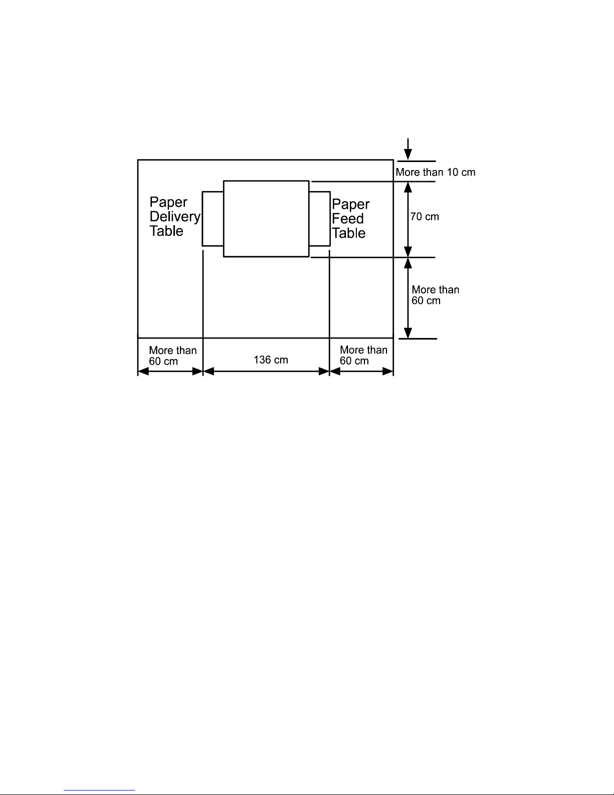
Place the machine near a power source, providing clearance as shown below.
C249I000.WMF
Page 25
INSTALLATION PROCEDURE
SM 1-3 C249
Installation
1.2 INSTALLATION PROCEDURE
1.2.1 MAIN UNIT
Accessory Check
Make sure that you have all the accessories listed below:
Description Q'ty
1. Master Spool.............................................................................. 2
2. Operating Instructions................................................................ 1
3. NECR (Ricoh version only)........................................................ 1
4. Model Name Plates (C249-22, and -52 only)............................. 1 set
C249I019.WMF
Page 26
INSTALLATION PROCEDURE
C249 1-4 SM
Installation Procedure
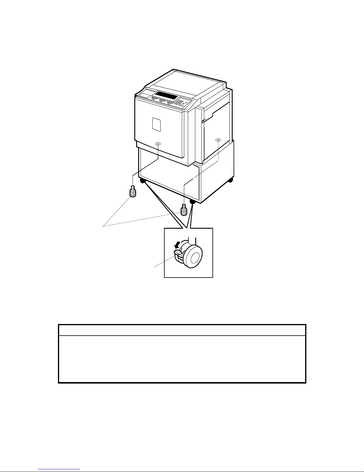
1. Unpack the box. When installing the optional table, mount the machine as
shown (there are 2 screws [A] packed with the table).
CAUTION
Only lift with the carrying handles on the bottom corners of the machine.
Secure the machine on the table with the 2 screws [A] provided. This
prevents the machine from falling from the table when the platen cover is
open.
Lock the casters of the table as shown [B], to prevent the machine from
moving (e.g. when the drum is set).
C249I014.WMF
[B]
[A]
Page 27
INSTALLATION PROCEDURE
SM 1-5 C249
Installation
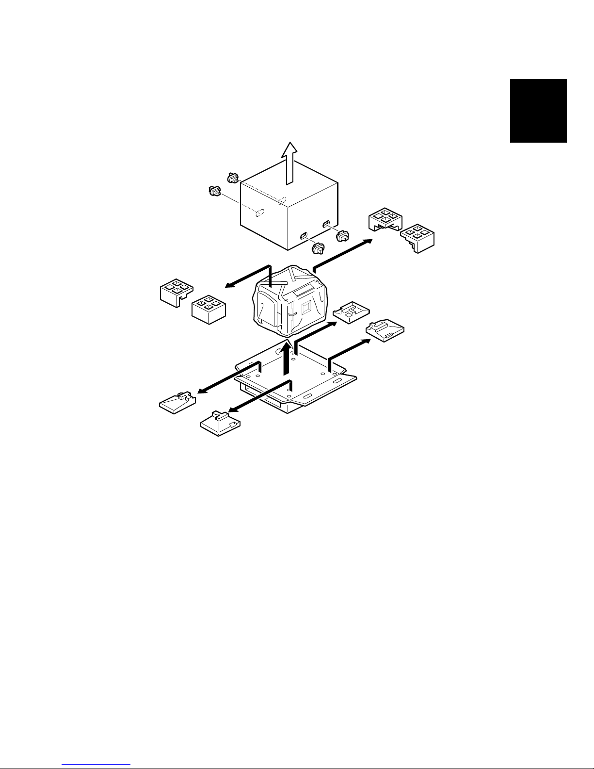
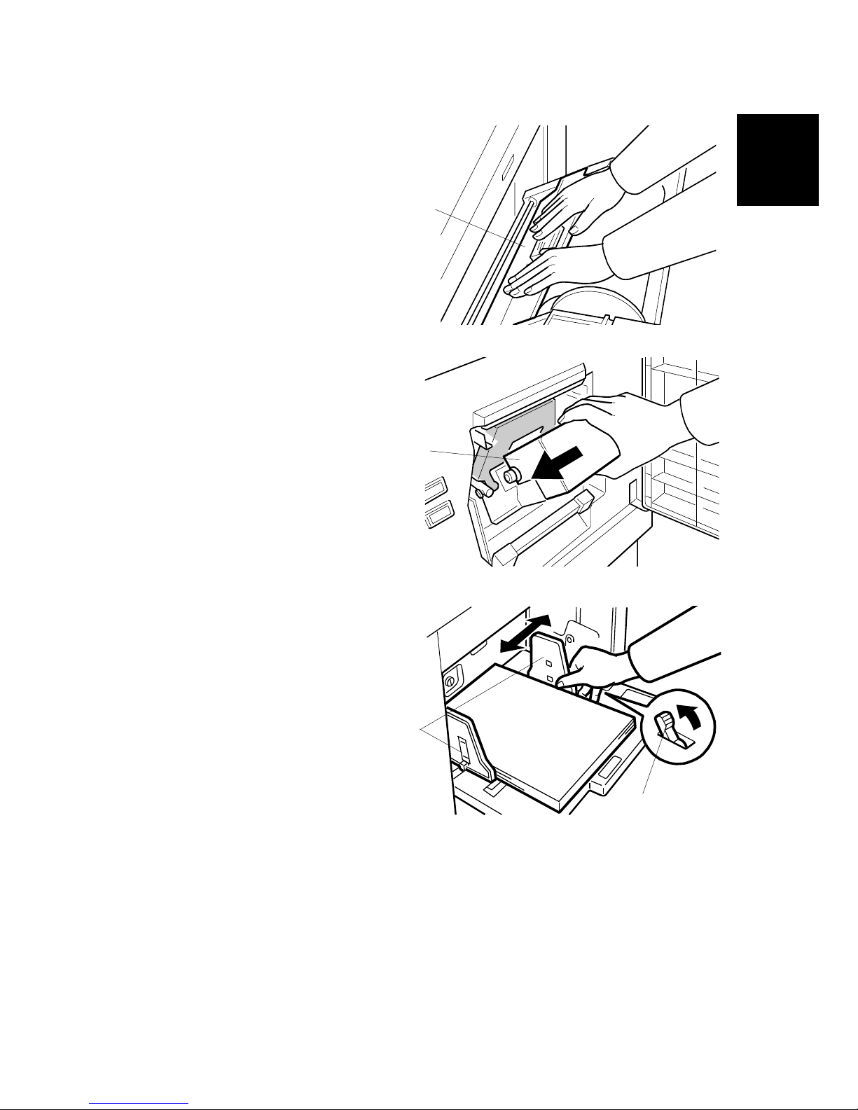
2. Remove the filament tape and string securing the covers and units as shown
above.
C249I907.WMF
C249I020.WMF
C249I908.WMF
C249I909.WMF
Page 28

INSTALLATION PROCEDURE
C249 1-6 SM
3. Pull out the master making unit, and
take out the accessory bag [A].
4. Insert both spools into a new master
roll.
5. Install the master roll as shown to the right.
6. Insert the leading edge of the master
roll under the platen roller. The arrows
[B] indicate the correct position of the
master leading edge.
C249I038.WMF
C249I030.WMF
C249I032.WMF
C249I910.WMF
[B]
[A]
Page 29
INSTALLATION PROCEDURE
SM 1-7 C249
Installation
7. Close the cover [C] using both hands.
8. Set the master-making unit.
9. Open the door, and insert a new ink
cartridge [D].
10. Open the paper table, and load a
stack of paper.
11. Make sure that the side plates [E]
touch the paper gently. Shift the lock
lever [F] in the direction of the arrow.
C249I031.WMF
C249I034.WMF
C249I028.WMF
[D]
[C]
[E]
[F]
Page 30
INSTALLATION PROCEDURE
C249 1-8 SM
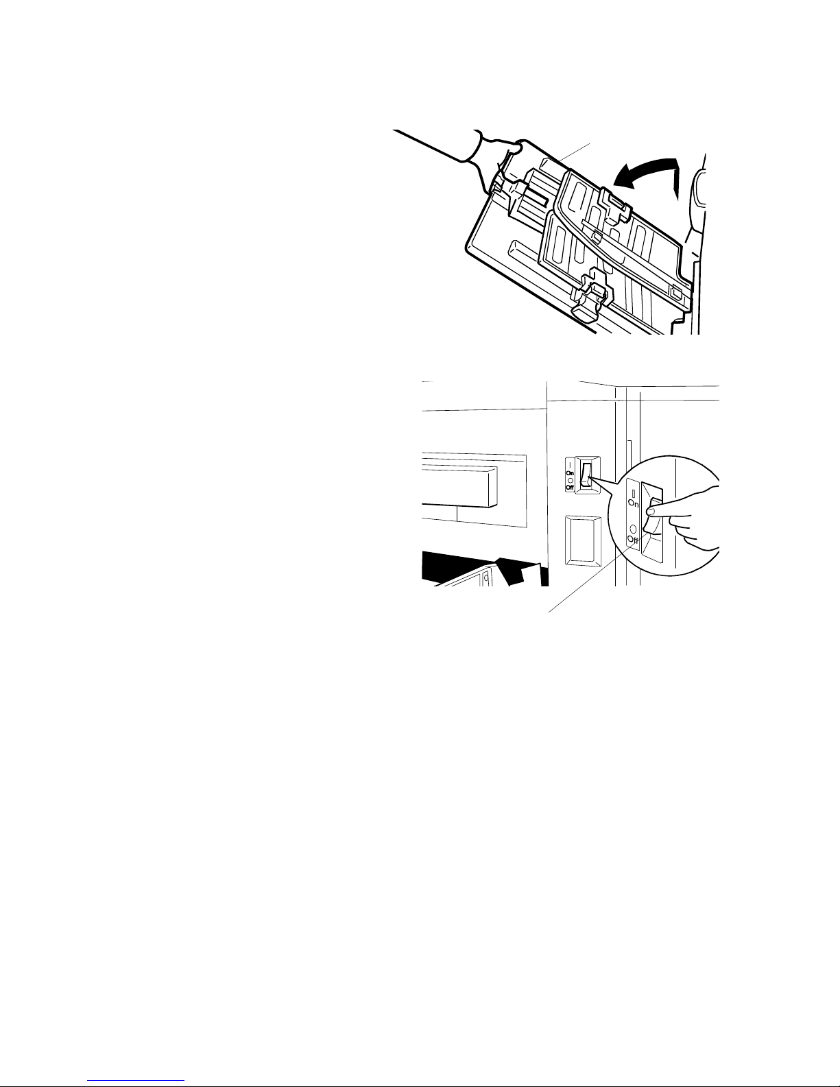
12. Raise the paper delivery table [G]
slightly, then gently lower it.
13. Lift the side plates and the end
plate, and adjust them to the
paper size.
14. Firmly insert the power plug in the
outlet.
15. Make sure that the wall outlet is near
the machine and easily accessible.
16. Turn on the main switch [H].
17. Press the “Economy mode” key while
holding down the “0” key, to supply
ink inside the drum.
18. Make some test copies.
C249I027.WMF
C249I026.WMF
[G]
[H]
Page 31

INSTALLATION PROCEDURE
SM 1-9 C249
Installation
1.2.2 BEFORE BEGINNING MACHINE OPERATION.
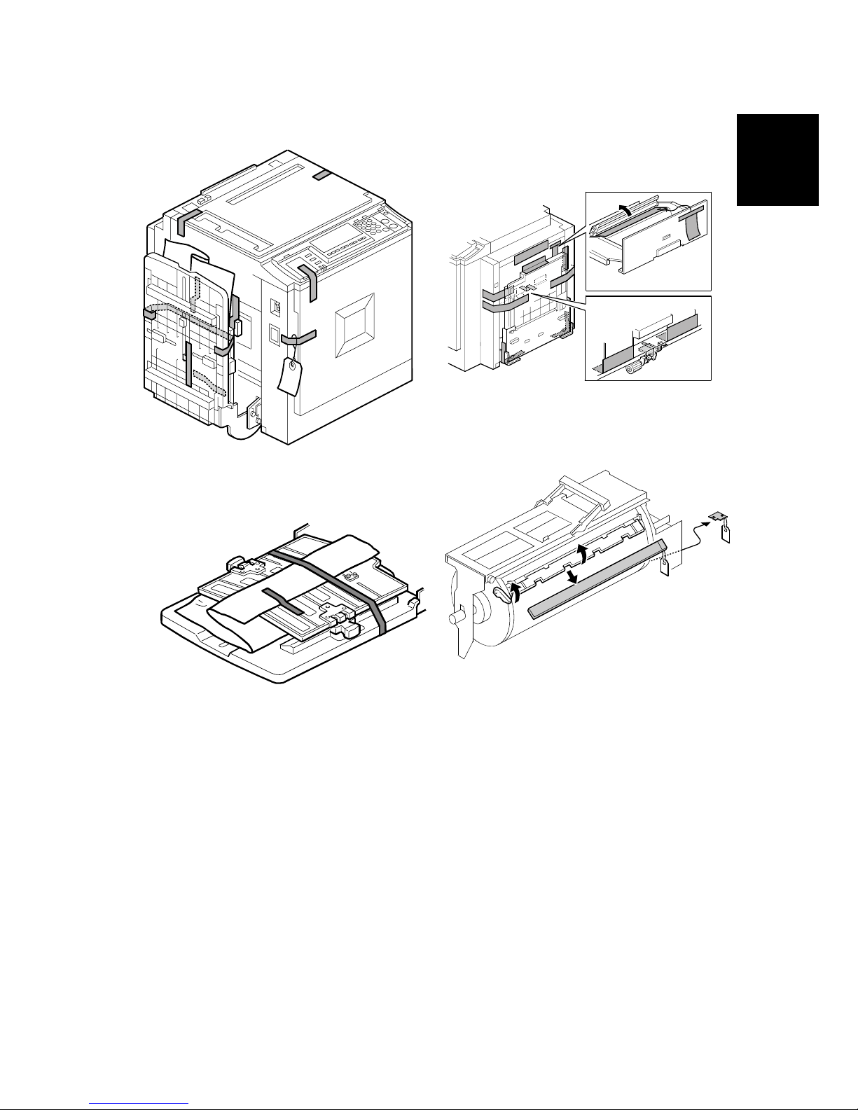
NOTE: Strips of tape and a styrene foam sponge have been added as shown
below to secure the Press Roller during transport. Please be sure to
remove the tape [A], sponge [B] and tag [C] by pulling the portion shown in
the illustration toward the front of the machine before beginning machine
operation.
NOTE: If they are not removed:
Paper jams or blank images may occur, due to the lack of pressure on the
Press Roller.
The tape may stick to the drum screen or Press Roller.
[A]
[B]
[C]
Rev.04/2004
⇒
Page 32

INSTALLATION PROCEDURE
C249 1-10 SM
1.2.3 PLATEN COVER INSTALLATION (OPTION)
Accessory Check
Check the quantity and condition of the accessories in the box against the following
list:
Description Q'ty
1. Stepped Screw............................................................................... 2
Installation Procedure
1. Install the platen cover [A] (2 screws).
C249I001.WMF
[A]
Rev.04/2004
Page 33

INSTALLATION PROCEDURE
SM 1-11 C249
Installation
1.2.4 ADF INSTALLATION (OPTION)
Accessory Check
Check the quantity and condition of the accessories in the box against the following
list:
Description Q'ty
1. Stepped Screw .......................................................................... 2
2. Screws....................................................................................... 3
3. Screwdriver................................................................................ 1
4. DF Exposure Glass.................................................................... 1
5. Decal - Exposure Glass............................................................. 1
6. Decal - Scale - mm .................................................................... 1
7. Decal - Scale - inch.................................................................... 1
8. Scale Guide ............................................................................... 1
9. Stabilizer Bracket....................................................................... 2
10. Thumbscrew .............................................................................. 4
11. Caution Label............................................................................. 1
Installation Procedure
1. Remove the strips of tape.
C249I002.WMF
Rev.04/2004
Page 34

INSTALLATION PROCEDURE
C249 1-12 SM
2. Remove the left scale [A] (2 screws).
3. Place the DF exposure glass [B] on the glass holder.
NOTE: When installing the DF exposure glass, make sure that the white point
[C] is positioned at the lower front side, as shown.
4. Peel off the backing [D] of the double-sided tape attached to the rear side of the
scale guide [E], then install the scale guide (2 screws removed in step 2).
5. Install the two stud screws [F].
6. Mount the DF by aligning the holes [G] in the DF with the stud screws, then
slide the DF to the front as shown.
7. Secure the DF unit with two screws [H].
C249I003.WMF
C249I004.WMF
[A]
[B]
[C]
[D]
[E]
[F]
[G]
[H]
Rev.04/2004
Page 35

INSTALLATION PROCEDURE
SM 1-13 C249
Installation
8. Connect the cables [I] and [J] to the main body.
9. Attach the scale decal [K] as shown.
10. Plug in the power cord, then turn the main switch on.
11. Make a full size copy using the ADF. Then check to make sure the side-to-side
and leading edge registrations are correct. If they are not, adjust their values
(do the adjustment procedures in section 5.7.3).
C249I018.WMF
C249I500.WMF
[I]
[J]
[K]
Rev.04/2004
Page 36

INSTALLATION PROCEDURE
C249 1-14 SM
ADF stabilizer installation
1. Attach the two stabilizer brackets [A] to the back of the table using the
thumbscrews (4 screws).
2. Attach the caution label [B], as shown.
CAUTION
This procedure must be done to prevent the machine from falling
backwards when the ADF is open.
C249I040.WMF
[A]
[B]
Rev.04/2004
Page 37

INSTALLATION PROCEDURE
SM 1-15 C249
Installation
1.2.5 TAPE MARKER (OPTION)
Accessory Check
Check the quantity and condition of the accessories in the box against the following
list:
Description Q'ty
1. Knob Screw (C210, C217, C218, C219, C222, C223, C225,
C228, C231, C237, C238, C247, C248 and C249 only) ...... 2
2. Screw M4 x 25 (C211, C212, C213, C214, C216, C224,
and C226 only) .................................................................... 2
3. Hexagon Nut M4 (C211, C212, C213, C214, C216, C224,
and C226 only) .................................................................... 2
4. Auxiliary Bracket (C226 only)............................................... 1
5. Auxiliary Bracket (C238, C247, and C249 only)................... 1
6. Screw M4 x 8 (C226, C238, C247 and C249 only).............. 2
7. Lock Washer (C226 only) .................................................... 1
8. Lock Washer........................................................................ 1
9. Tape .................................................................................... 1
Rev.04/2004
Page 38

INSTALLATION PROCEDURE
C249 1-16 SM
Installation Procedure
- For C238, C247 and C249 -
1. Turn off the main switch and unplug the power cord.
2. Remove the paper delivery plate (4 screws).
3. Cut the cap [A] off the rear cover of the main body with pliers, then connect the
tape marker cable to the main body.
4. Install the auxiliary bracket [B] (#C5326502) on the tape marker with M4 x 8
screws (accessories) [C].
NOTE: Install the lock washer [E] (accessories) with the lower of the two
screws.
5. Install the tape marker on the main body with two knob screws [D]
(accessories) in the two outer holes in the tape marker bracket.
6. Reinstall the paper delivery plate.
7. Refer to "Common Steps".
C249I994.WMF
C249I536.WMF
[B]
[C]
[D]
[E]
[A]
Rev.04/2004
Page 39

INSTALLATION PROCEDURE
SM 1-17 C249
Installation
- For C231 , C237, and C248 -
1. Turn off the main switch and unplug the power cord.
2. Remove the paper delivery table (2 screws).
3. Remove the paper delivery plate (4 screws).
4. Cut the cap [A] off the rear cover with pliers, then connect the tape marker
cable to the main body.
5. Install the tape marker on the main body with two knob screws [B]
(accessories) in the two outer holes in the tape marker bracket.
NOTE: 1) Tighten the knob screws with a screwdriver to prevent them from
coming loose.
2) Install the lock washer [C] (accessories) with the lower of the two
knob screws.
6. Reinstall the paper delivery plate and paper delivery table.
7. Refer to "Common Steps".
C249I536.WMF
C249I533.WMF
[A]
[B]
[C]
Rev.04/2004
Page 40

INSTALLATION PROCEDURE
C249 1-18 SM
- For C226 -
Main Body:
1. Turn off the main switch and unplug the power cord.
2. Remove the rear cover (6 screws).
3. Replace the screw [A], to secure the AC drive board with M4 x 25 screws
(accessories).
4. Reinstall the rear cover.
5. Install the auxiliary bracket [B] on the main body with the hexagon nut [D]
(accessories) as shown.
NOTE: Install the lock washer [C] (accessories) with the nut.
Tape Marker:
6. Install the tape marker on the auxiliary bracket with two M4 x 8 screws [E]
(accessories).
7. Install the lock washer [F] (accessories) with one of the two screws.
8. Refer to "Common Steps".
C238I516.PCX
C249I517.WMF
[A]
[B]
[C]
[D]
[F]
[E]
Rev.04/2004
Page 41

INSTALLATION PROCEDURE
SM 1-19 C249
Installation
- For C210, C218, C219, C222, and C223 -
1. Turn off the main switch and unplug the power cord.
2. Install the tape marker on the main body with two knob screws [A]
(accessories) in the two outer holes in the tape marker bracket.
NOTE: 1) Install the lock washer [B] (accessories) with the lower of the two
knob screws.
2) .Tighten the knob screws with a screwdriver to prevent them from
coming loose
3. Refer to “Common Steps”.
— For Model C228 and the models on which the new Paper Delivery Table is
installed —
Use the two holes in the tape marker bracket [C] as shown below.
C238I502.PCX
C238I504.PC
X
[A]
[B]
[C]
Rev.04/2004
Page 42

INSTALLATION PROCEDURE
C249 1-20 SM
- For C217 and C225 -
1. Turn off the main switch and unplug the power cord.
2. Install the tape marker on the main body with two knob screws [A]
(accessories) in the two inner holes of the tape marker bracket.
NOTE: 1) Install the lock washer [B] (accessory) with the lower of the two knob
screws..
2) Tighten the knob screws with a screwdriver to prevent them from
coming loose
3. Refer to “Common Steps”.
C238I503.PCX
[A]
[B]
Rev.04/2004
Page 43

INSTALLATION PROCEDURE
SM 1-21 C249
Installation
- Common Steps -
1. Remove the small cap in the rear cover of
the main body [A]. Then, connect the tape
marker cable [B] to the main body, and install
the connector cover [C] using one of the rear
cover securing screws. (For C238, C247 and
C249, this has already been done.)
2. Open the tape marker cover [D]. Then,
insert the leading edge of the tape into
the tape entrance until it stops as
shown in the illustration [E].
NOTE: Be sure that the tape is
installed in the proper direction.
If it is not, the tape marker will
not work correctly.
3. Turn on the main switch of the main
body and set the SP mode to activate
the tape marker. (Refer to the service
program table.)
4. Turn on the tape marker switch [F].
5. Press the tape cut button [G] to cut off
the leading edge of the tape.
6. Check the tape marker operation using
the Memory/Class modes of the main
body.
C238I518.PCX
C238I519.PCX
C238I520.PCX
C238I521.PCX
[A]
[B]
[C]
[D]
[E]
[F]
[G]
Rev.04/2004
Rev.04/2004
Page 44

INSTALLATION PROCEDURE
C249 1-22 SM
1.2.6 OPTIONAL DRUMS
There are two types of drum units:
A3 Size: Color drum
A4 Size: Black drum (Black ink only)
1. Remove the protective sheet [A] and the lock [B] from the drum unit.
2. Remove the tape securing the ink holder.
3. Attach a color indicator decal to the drum case. The decal must be the same
color as the ink in use.
4. Remove the drum unit.
5. Leave the master wrapped around the removed drum to protect the drum from
dust and from drying.
6. Keep the removed drum unit in the drum case.
7. Install the drum unit.
NOTE: The color drum indicator (or A4 drum indicator) on the operation panel
stays lit when a drum is mounted in the machine.
8. Remove the ink cartridge cap.
9. Insert the ink cartridge in the ink holder.
C249I534.WMF
C249I020.WMF
[A]
[B]
Rev.04/2004
Page 45

PREVENTIVE MAINTENANCE
Page 46

Page 47

MAINTENANCE TABLE
2. PREVENTIVE MAINTENANCE
2.1 MAINTENANCE TABLE
The following items should be maintained periodically. There are two sets of
intervals - one based on time and the other based on print count. For maintenance
items with entries in both of them, use whichever comes first.
Preventive
Maintenance
C: Clean, R: Replace, L: Lubricate, A: Adjust
Time Print Counter Interval
Item
6M 1Y 2Y 3Y
1M 1.2M
2M 2.4M 3M
EM NOTE
Scanner/Optics
Exposure Lamp C C C C Dry Cloth
Mirror/Reflector C C C C Soft Cloth
Scanner Guide Rail C C C C Dry Cloth
Platen Cover / White
Plate
C C C C
Damp
Cloth
Exposure Glass C C C C Dry Cloth
Master Feed
Thermal Head C Alcohol
Platen Roller
C C C C
Damp cloth
and water
Master Eject Rollers C C C C Alcohol
Drum Master
Sensor
C Dry Cloth
Paper Feed
Paper Pick-up Roller
C C R C R R
Damp
Cloth
Paper Feed Roller
C C R C R R
Damp
Cloth
Pick-up Roller/Feed
Roller Shafts [A]
L L L
Motor Oil
(SAE #20)
Friction Pad
C C R C R R
Damp
Cloth
Press Roller C C R C R R Alcohol
Table Fulcrum
Shafts [B]
L L L
Motor Oil
(SAE #20)
Table Racks [C]
L L L
Grease
(Alvania
#2)
Paper Delivery
Transport Belts
R R R
Paper End Sensor C C C C Dry Cloth
Registration/Exit
Sensors
C C C C Dry Cloth
Registration Roller C C C C Dry Cloth
SM 2-1 C249
Page 48

MAINTENANCE TABLE
C249 2-2 SM
Time Print Counter Interval
Item
6M 1Y 2Y 3Y
1M 1.2M
2M 2.4M 3M
EM NOTE
Drum and Ink Supply
Cloth Screen R R R
Ink Roller One-way
Clutch
R ! 3.8.5
Drum Drive Gears
and Cam [D] L L L
Grease
(Alvania
#2)
Ink Pump Gears [E]
L L L
Motor Oil
(SAE #20)
In/Outside of Drum C C C C Alcohol
Ink Nozzle C C C C Alcohol
Black Patch [G] C C C C Dry Cloth
Others
Main Drive Timing
Belt Tension
A
! 3.8.9
Printing Pressure
Spring Hooks [F] L L L
Grease
(Alvania
#2)
Press Roller
Release Lever
Position
A
ADF (Option)
DF Feed Rollers C C C C Dry Cloth
[C]
[D]
[B]
[A]
[F]
[E]
[G]
Page 49

REPLACEMENT AND ADJUSTMENT
Page 50

Page 51

GENERAL CAUTION
SM 3-1 C249
Replacement
&
Adjustment
3. REPLACEMENT AND ADJUSTMENT
Only items that were changed or newly added to the C249 model are described.
3.1 GENERAL CAUTION
CAUTION
Turn off the main power switch and unplug the machine before attempting
any of the procedures in this section.
NOTE: This manual uses several symbols. The meaning of those symbols are as
follows:
! : See or Refer to : screw : connector : E-ring : Clip
3.2 PRINT KEY / START KEY
[A]: Key Cover
[B]: Print start key
[C]: Master making key
C249R119.WMF
C249R120.WMF
C238A086.WMF
[A]
Page 52

COVERS / BOARDS
C249 3-2 SM
3.3 COVERS / BOARDS
3.3.1 FRONT COVER / PANEL
[A]: Front door ( x 4)
[B]: Front cover ( x 6)
[C]: Upper right cover ( x 2)
[D]: Operation panel ( x 4, x 1)
C238R006.WMF
[B]
[A]
[C]
[D]
Page 53

COVERS / BOARDS
SM 3-3 C249
Replacement
&
Adjustment
3.3.2 REAR COVERS
[A]: Rear left cover ( x 5)
[B]: Rear right cover ( x 3)
[C]: Upper left cover ( x 2)
[D]: Rear upper cover
3.3.3 MPU
• Rear left cover, Rear right cover (! 3.3.2)
[A]: MPU ( x 17, x 6, 9 clamps)
CAUTION: Move the RAM [B] from the old board to the new one, so that the SP
mode settings will be transferred to the new board. Adjust the master
end sensor (! 3.6.10) after installing the new MPU.
C238R007.WMF
C238R008.WMF
[A]
[B]
[C]
[D]
[A]
[B]
Page 54

COVERS / BOARDS
C249 3-4 SM
3.3.4 PSU
• Upper left cover (! 3.3.2)
• Master eject unit (! 3.5.1)
[A]: PSU ( x 5, x 2, 2 clamps)
CAUTION: When the PSU is replaced, the thermal head voltage returns to the
default. Adjust the thermal head voltage (! 3.6.6) after installing the
new board.
C238R009.WMF
[A]
Page 55

SCANNER
SM 3-5 C249
Replacement
&
Adjustment
3.4 SCANNER
3.4.1 EXPOSURE GLASS / SCALES
[A]: Left scale ( x 2)
[B]: Upper scale ( x 3)
[C]: Exposure glass
3.4.2 SBU AND LAMP STABILIZER / SCANNER MOTOR
• Left scale, Upper scale, Exposure glass
(! 3.4.1)
• Upper right cover (! 3.2.1)
[A]: SBU cover ( x 4)
[B]: SBU ( x 1, x 5)
C238R038.WMF
C238R039.WMF
[A]
[B]
[C]
[A]
[B]
Page 56

SCANNER
C249 3-6 SM
[C]: Lamp stabilizer ( x 2, 3 standoffs)
[D]: Scanner motor ( x 2, x 1, 1 spring)
3.4.3 SCANNER H.P. SENSOR / PLATEN COVER SENSOR
• Left scale, Upper scale, Exposure glass (! 3.4.1)
• Operation panel (! 3.3.1)
• Rear upper cover (! 3.3.2)
[A]: Platen cover sensor ( x 1)
[B]: Left stay ( x 1)
[C]: Scanner H.P. sensor ( x 1)
C238R041.WMF
C238R042.WMF
C238R043.WMF
[D]
[A]
[B]
[C]
[C]
Page 57

SCANNER
SM 3-7 C249
Replacement
&
Adjustment
3.4.4 EXPOSURE LAMP (XENON LAMP)
• Move the first scanner next to the opening in the frame.
• Exposure glass (! 3.4.1)
• [1]: Left stay (! 3.4.3)
[A]: Platen base ( x 1, x 5)
[B]: Rear frame ( x 1, x 2)
[C]: Front frame ( x 5)
[D]: Exposure lamp ( x 1)
NOTE: After installing the lamp, press the lamp holder [E] up to the original
position so that it can hold the lamp properly.
C238R044.WMF
C238R045.WMF
[A]
[B] [C]
[1]
[D]
[E]
Page 58

SCANNER
C249 3-8 SM
3.4.5 SCANNER WIRES
• Move the first scanner next to the opening in the frame.
• Exposure glass (! 3.4.1)
• SBU cover (! 3.4.2)
• Left stay (! 3.4.3)
• Rear and front frames (! 3.4.4)
1. First scanner ([1]: 2 pins)
NOTE: The drawings show only the front side. Repeat to remove components
on the other side.
[A]: Wire tension brackets (2 springs, x 2)
[B]: Scanner drive pulleys (2 Allen screws)
[C]: Scanner wires
Installation
1. Wrap the new scanner wire around the pulley as shown ", then temporarily
secure the pulley with tape.
2. Re-install the first scanner. Then secure the first and second scanner with the
scanner positioning pins (P/N A0069104), as shown in the illustration on the
next page.
3. Wind the new scanner wire around the scanner drive pulley in the correct way,
as shown.
4. Wind the end of the new wire with the ball as shown (
#).
5. Wind the end of the new wire with the ring as shown ($,%, and &).
6. Connect the tension spring to the wire tension bracket (&).
7. Wind the new scanner wire for the other side as well.
C238R046.WMF
C238R029.WMF
[B]
[C]
[D]
[A]
[1]
Page 59

SCANNER
SM 3-9 C249
Replacement
&
Adjustment
8. Secure the first scanner with the pins [E].
9. Tighten the screw securing the tension bracket [F].
10. Secure the scanner drive pulley [G] (1 Allen screw).
11. Remove the scanner positioning pins [I] (P/N: #A0069104).
12. Slide the scanner to the left and right several times, then set the scanner
positioning pins to check the clamp position and wire tension bracket position
again.
C238R047.WMF
C238R048.WMF
[E]
[F]
[G]
[I]
Page 60

SCANNER
C249 3-10 SM
3.4.6 IMAGE ADJUSTMENT
Purpose: To adjust the image position on prints by changing the SP settings.
Adjust the following in the order given below.
SP6-10: Master writing speed (! 5.7.3)
↓
SP6-21: Paper registration position (! 5.7.3)
↓
SP6-05: Scanning speed - platen (! 5.7.3)
SP6-06: Scanning speed - ADF
↓
SP6-03: Scanning start position - platen (! 5.7.3)
SP6-04: Scanning start position - ADF
↓
SP6-01: Main scan position - platen (! 5.7.3)
SP6-02: Main scan position - ADF
↓
SP6-31: SBU calibration (! 5.7.4)
Page 61

MASTER EJECT
SM 3-11 C249
Replacement
&
Adjustment
3.5 MASTER EJECT
3.5.1 MASTER EJECT UNIT
[A]: Master eject unit ( x 1, x 2, 1 clamp)
C249R001.WMF
[A]
Page 62

MASTER FEED
C249 3-12 SM
3.6 MASTER FEED
3.6.1 MASTER MAKING UNIT
[A]: Master making unit ( x 2)
3.6.2 THERMAL HEAD
1. Connect the power plug. Then turn on the main switch to access SP mode.
2. Select SP5-74 (T/H driving motor - up), then press the enter (#) key and turn off
the main switch.
NOTE:
1) The thermal head is released, after about 2 seconds. (There is almost
no sound of operation.)
2) The thermal head does not separate, unless it releases as mentioned
above.
C249R121.WMF
[A]
Page 63

MASTER FEED
SM 3-13 C249
Replacement
&
Adjustment
• Master making unit (! 3.6.1)
• Open the platen roller unit [1].
[A]: T/H upper cover ( x 2)
[B]: T/H side cover ( x 1)
• Close the platen roller unit [1].
[C]: Thermal head ( x 2)
C249R049.WMF
C249R122.WMF
[1]
[C]
[A]
[B]
[1]
Page 64

MASTER FEED
C249 3-14 SM
1. Turn the thermal head clockwise and remove a nail (").
2. Turn the thermal head counterclockwise, and remove a nail (#).
3. Remove the thermal head slowly.
NOTE: If you cannot access SP modes, open the master making unit and loosen
the 2 screws [D].
C249R116.WMF
C249R110.WMF
[D]
Page 65

MASTER FEED
SM 3-15 C249
Replacement
&
Adjustment
Installation
1. Insert in the nails (") to the operation side and middle.
2. Turn the thermal head counterclockwise and insert in the nail (
#) to in front.
3. Turn the thermal head clockwise and insert in the nail (
$) to the non-operation
side.
Make sure to follow the above procedure or the thermal head will not be installed
correctly.
1) Fit the base’s springs [A] over the protrusions [B] on the underside of the
thermal head (6 points).
2) While fitting the tops of the springs [A] over the protrusions on the underside
of the thermal head.
3) Make sure that all protrusions are properly fitted into the springs.
CAUTION: Adjust the thermal head voltage (! 3.6.6) after installing the new
thermal head.
C249R117.WMF
C249R030.WMF
[A]
[B]
Page 66

MASTER FEED
C249 3-16 SM
3.6.3 DUCT PLATE HP SENSOR / DUCT PLATE MOTOR
• Master making unit (! 3.6.1)
[A]: Rear cover ( x 2)
[B]: Duct plate HP sensor ( x 1, x 1)
[C]: Rear rail bracket ( x 2)
[D]: Duct plate motor ( x 1, x 2)
C249R101.WMF
C249R102.WMF
[A]
[B]
[C]
[D]
Page 67

MASTER FEED
SM 3-17 C249
Replacement
&
Adjustment
3.6.4 CUTTER UNIT
[A]: Cutter unit ( x 1, x 1)
3.6.5 THERMAL HEAD DRIVING UNIT
• Thermal head (! 3.6.2)
• Rear cover (! 3.3.2)
• Cutter unit (! 3.6.4)
[A]: Anti-Static roller ( x 2)
[B]: Thermal head driving unit ( x 2, x 2)
C249R103.WMF
C249R105.WMF
[A]
[B]
[A]
Page 68

MASTER FEED
C249 3-18 SM
3.6.6 THERMAL HEAD VOLTAGE ADJUSTMENT
CAUTION
This adjustment is always required when the thermal head or PSU has been
replaced.
Purpose: To maintain master making quality and extend the lifetime of the thermal
head.
Standard: Refer to the voltage value (X) printed on the thermal head. The value
varies from one thermal head to another.
The adjustment voltage should be between X and X - 0.1 V.
Tools: Circuit tester
• Upper left cover (! 3.3.2)
• Read the voltage value on the
decal on the thermal head.
1. Slide out the master making unit.
CAUTION: Never turn VR1
clockwise rapidly
while the master
making unit is
connected. The T/H
will be damaged if too
much voltage is
supplied suddenly.
2. Connect the positive terminal of a
circuit tester to TP701 and the
negative terminal to TP702 .
CAUTION: If the output and
ground terminals
touch each other, the board will be damaged.
3. Connect the power plug, and turn on the main switch to access SP mode.
4. Select SP5-12 (Thermal head signal output).
5. Press the Start key. Power is continuously supplied to the thermal head, so
press the Stop key if you cannot finish the adjustment quickly.
A beeper sounds while the power is being supplied.
6. Measure the voltage, and turn VR1 so that the value becomes between “+0”
and “-0.1” volts from the value on the thermal head decal.
C238R012.WMF
Page 69

MASTER FEED
SM 3-19 C249
Replacement
&
Adjustment
3.6.7 DUCT JAM SENSOR ADJUSTMENT
Ensures that the sensor detects when a master remains in the duct.
Standard: 0.5 volts (within “+0.1” and “-0.1”volts)
Tools: Circuit tester
• Rear cover (! 3.3.2)
1. If a master remains in the duct, remove the master from the duct.
2. Connect the terminals of a circuit tester to TP102 and a grounded place (e.g.
iron base)
3. Connect the power plug, and turn on the main switch to access SP mode.
4. Select SP6-52 (Duct jam sensor voltage).
5. Press the Print Start key.
6. Measure the voltage, and turn VR102 so that the value becomes between “-
0.1” and “+0.1” volts from the standard value (0.5 volts)
NOTE: When the value of the voltage does not become the standard value, adjust
the threshold level of the duct jam sensor. (SP6-52 : Duct jam sensor
voltage)
Standard Value
Master being
Threshold level (SP6-52)
Standard Value
Master nothing
Above 2.0V 2.0V
0.5 ±0.1V
C249R123.WMF
C249R124.WMF
C249R113.WMF
Page 70

MASTER FEED
C249 3-20 SM
3.6.8 MASTER EDGE SENSOR ADJUSTMENT
Ensures that the sensor detects the leading edge of the master.
Standard: 2.0 volts (within “+0.1” and “-0.1”volts)
Tools: Circuit tester
• Rear cover (! 3.3.2)
1. Connect the terminals of a circuit tester to TP103 and a grounded place (e.g.
iron base)
2. Connect the power plug, and turn on the main switch to access SP mode.
3. Select SP6-51 (Master edge sensor voltage).
4. Remove the lower master tray.
5. Pull out the master-making unit from the machine and open the master set
cover.
6. Insert the leading edge of the master under the master tension roller, then
close the master set cover and reinstall the master-making unit to the machine.
7. Measure the voltage, and turn VR103 so that the value becomes between “-
0.1” and “+0.1” volts from the standard value (2.0 volts).
NOTE: When the value of the voltage does not become the standard value, adjust
the threshold level of the master edge sensor. (SP6-51 : Master edge
sensor voltage)
Standard Value
Master being
Threshold level (SP6-51)
Standard Value
Master nothing
2.0 ±0.1V
2.8V Above 3.3V
C249R133.WMF
Page 71

MASTER FEED
SM 3-21 C249
Replacement
&
Adjustment
3.6.9 2ND DRUM MASTER SENSOR ADJUSTMENT
Ensures that the sensor detects if there is a master on the drum.
Standard: 2.0 volts (within “+0.1” and “-0.1”volts)
Tools: Circuit tester
• Rear cover (! 3.3.2)
1. Confirm that the master is wrapped on the drum.
2. Connect the terminals of a circuit tester to TP104 and a grounded place (e.g.
iron base)
3. Connect the power plug, and turn on the main switch to access SP mode.
4. Select SP6-53 (2nd drum master sensor voltage) and press the master-making
key.
5. Measure the voltage, and turn VR104 so that the value becomes between “-
0.1” and “+0.1” volts from the standard value (2.0 volts).
6. Turn off the main switch, then remove the master that is wrapped around the
drum and install the drum in the main body.
7. Turn on the main switch to access SP mode.
8. Select SP6-53 (2nd drum master sensor voltage) and press the master-making
key.
9. Check if the value of the voltage becomes below 0.8 volts.
10. If the voltage is not correct, clean the black patch [A] on the screen.
NOTE: When the value of the voltage does not become the standard value, adjust
the threshold level of the 2nd drum master sensor. (SP6-53 : 2nd drum
master sensor voltage)
Standard Value
Master being
Threshold level (SP6-53)
Standard Value
Master nothing
2.0 ±0.1V
1.0V Below 0.8V
C249R126.WMF
[A]
Page 72

MASTER FEED
C249 3-22 SM
3.6.10 MASTER END SENSOR ADJUSTMENT
Ensures that the sensor detects the end mark (a solid black area) on the master
roll.
Standard: 1.8 volts (within “+0.1” and “-0.1” volts)
Tools: Circuit tester, the core of a used master roll (the core has no master)
• Rear cover (! 3.3.2)
1. Connect the terminals of a circuit tester to TP101 and to a grounded place (e.g.
iron base).
2. Put a piece of master [A] on the used master roll.
3. Place the core of the used master roll inside the master-making unit, and close
the master-making unit.
NOTE: Detect a low fiber content paper side of a piece of paper to the master
end sensor.
4. Connect the power plug, and turn on the main switch.
5. Measure the voltage, and turn VR101 so that the value becomes between “-
0.1” and “+0.1” volts from the standard value (1.8 volts).
NOTE: When the value of the voltage does not become the standard value, adjust
the threshold level of the master end sensor. (SP6-50 : Master end sensor
voltage)
Standard Value
Master being
Threshold level (SP6-50)
Standard Value
Master nothing
Below 1.8V 1.9V
2.0 ±0.1V
TP101
VR101
C249R118.WMF
C249R114.WMF
[A]
Page 73

PAPER FEED
SM 3-23 C249
Replacement
&
Adjustment
3.7 PAPER FEED
3.7.1 PICK-UP ROLLER / PAPER FEED ROLLER / FRICTION PAD
• Lower the paper table.
[A]: Pick-up roller ( x 1)
[B]: Paper guide ( x 1)
[C]: Feed roller ( x 1)
[D]: Friction pad
[E]:
C249R115.WMF
[A]
[B]
[C]
[D]
Page 74

PAPER FEED
C249 3-24 SM
3.7.2 PAPER SEPARATION PRESSURE ADJUSTMENT
Purpose: To ensure that the friction pad
exerts sufficient pressure for smooth
printing paper separation.
Default: The next position to the top.
Adjust the paper separation pressure by
loosening and moving the adjusting screw
[A] up or down.
Moving up the screw ⇒ Increases the
paper separation pressure
Moving down the screw ⇒ Decreases the
paper separation pressure
Tighten the screw after the adjustment.
C238R031.WMF
[A]
Page 75

PAPER FEED
SM 3-25 C249
Replacement
&
Adjustment
3.7.3 PAPER WIDTH DETECTION BOARD
• Lower the paper table.
[A]: Paper table ( x 1, x 2)
[B]: Table cover ( x 5, 3 washers)
[C]: Sensor cover ( x 2)
[D]: Paper width detection board ( x 1, x 1)
C238R018.WMF
C238R019.WMF
C238R020.WMF
[A]
[B]
[C]
[D]
Page 76

PRINTING
C249 3-26 SM
3.8 PRINTING
3.8.1 PRESS ROLLER
CAUTION
Take care to avoid possible injury. If the printing pressure release arms
disengage, the press roller will be pulled upwards suddenly.
• Remove the drum.
[A]: Press roller ( x 1)
The bearings on the rear and front differ. During installation, ensure that the
bearing with the stopper [B] is positioned towards the rear of the machine.
C238R037.WMF
[A]
[B]
Page 77

PRINTING
SM 3-27 C249
Replacement
&
Adjustment
3.8.2 PRESS ROLLER RELEASE LEVER ADJUSTMENT
Purpose: To maintain the correct clearance between the press roller arms and
press roller lock levers. This ensures that the press roller is correctly released and
pressed against the drum when the press roller release solenoid is energized.
Standard: 0.7 to 1.2 mm
Tools: A thickness gauge
• Front cover (! 3.3.1)
• Rear covers (! 3.3.2)
1. Turn the drum manually until the drum master clamper on the drum moves into
the lowest position. (This is when the high points of the cams on the drum
flanges meet with the cam followers on both ends of the press roller.)
• To find out the correct position of the drum for the adjustment, look at the
rear end of the drum shaft. The recess on the drum drive gear meets the hole
[A] in the bracket when the drum is in the correct position.
2. Using a thickness gauge, measure the clearance [B] between the press roller
arm [C] and the press roller lock lever [D] (rear side). It should be between 0.7
and 1.2 mm.
3. If it is not correct, adjust the position of the press roller lock lever after
loosening the two screws [E].
4. Repeat steps 2 and 3 for the front side.
C238R001.WMF
C238R051.WMF
[A]
[B]
[C]
[D]
[E]
Page 78

PRINTING
C249 3-28 SM
3.8.3 PRINTING PRESSURE ADJUSTMENT
Improves print results without decreasing the run length.
Standard: Within 17 ± 0.2 mm
1. Adjust the distance [A] to 17 ± 0.2 mm by turning the adjusting bolt [B].
2. Repeat the same procedure for the printing pressure spring at the nonoperation side.
C249R127.WMF
[A]
[B]
Page 79

DRUM
SM 3-29 C249
Replacement
&
Adjustment
3.9 DRUM
3.9.1 PREPARATION
Before attempting any of the procedures in this section, wipe off the ink around the
ink roller. To do this, set SP2-10 (ink detection) to OFF, and feed paper until ink
ends.
After finishing the required procedures in this section, do not forget to return SP210 to the default (ink detection on).
3.9.2 CLOTH SCREEN
• Remove the drum
1. Remove the drum upper bracket ( x 4).
2. Release the stopper [A], then rotate the drum until the master clamper faces
top.
3. Remove the cloth screen [B] ( x 4).
C238R053.WMF
C238R054.WMF
[A]
[B]
Page 80

DRUM
C249 3-30 SM
Installation
• Do not scratch the cloth screen or metal screen.
• Properly insert the edge of the mylar [A] on the cloth screen under the mylar [B]
on the metal screen, as shown above.
Otherwise, ink will leak from the trailing edge of the master on the drum during a
long printing run.
• Make sure that the correct side of the screen is facing up. In addition, make sure
that the stays for securing the cloth screen are positioned correctly. (Refer to the
upper right illustration.)
• When replacing the cloth screen, spread the screen around the metal screen
while strongly pulling the stay [C]. Adjust the stay so that it is parallel to the
master clamper, then tighten the screws.
• Make sure that the cloth screen is not wrinkled while spreading it around the
drum.
C238R055.WMF
C238R056.WMF
C238R057.WMF
[A]
[B]
Inside
Outside
[C]
Page 81

DRUM
SM 3-31 C249
Replacement
&
Adjustment
3.9.3 CLAMPER / METAL SCREEN
• Remove the drum
• Cloth screen (! 3.9.2)
[A]: Clamper lever (1 hexagon screw)
[B]: Clamper - open the clamping plate [C], then remove the clamper.
NOTE:
1) Do not allow ink to get on the inside of the clamping plate [C]. If it is
dirty with ink, the master may slip off and the image position on the
prints will move toward the trailing edge of the prints during a
printing run.
2) Use a cloth dampened with water to clean the inside of the clamping
plate [C]. Never use alcohol or other solvents. The clamping force of
the magnet will be weakened.
[D]: Tape (do not lose it)
[E]: Metal screen ( x 12)
C238R058.WMF
C238R002.WMF
[A]
[B]
[C]
[D]
[E]
Page 82

DRUM
C249 3-32 SM
Installation
• Make sure that the correct end of the metal screen is overlapping. (The right side
overlaps, as viewed from the non-operation side, as shown above.)
• The 4 screws holding the drum master clamper are longer than the 12 screws
holding the metal screen, although they are similar in appearance. Be careful not
to mix them up or use the wrong screws.
• When installing the metal screen, secure the trailing edge first with the 2 screws.
Then, tighten the other screws while removing the slack from the screen. Make
sure that the gap between the drum flanges and the screen is 0.3 mm or less, as
shown above. (The two holes [A] on the trailing side are round holes and the
other holes are long holes, to allow for the removal of the slack.)
• Do not scratch the cloth screen or metal screen.
C238R059.WMF
[A]
Page 83

DRUM
SM 3-33 C249
Replacement
&
Adjustment
3.9.4 INK PUMP ADJUSTMENT
Purpose: To ensure the smooth operation of the ink pump plunger by properly
positioning its holder.
• Remove the drum
[A]: Lower pump cover ( x 2)
[B]: Upper pump cover ( x 3)
1. Remove the E-ring [C] to free the plunger from the pump drive slider [D].
2. Loosen the two screws securing the holder [E]. (Do not remove the holder.)
3. Push the plunger [F] until it reaches the bottom.
NOTE: The end of the plunger [F] must not stick out from the holder [E].
C238R014.WMF
C238R015.WMF
[A]
[B]
[C]
[D]
[E]
[F]
Page 84

DRUM
C249 3-34 SM
4. Check that the piston motion is smooth.
5. If the motion is stiff, loosen the pump screws [G] and adjust the pump position.
6. After tightening, repeat step 4 and step 3.
7. Re-tighten the two screws [H].
8. Check that the piston motion is smooth.
9. Reinstall the E-ring [C].
C238R016.WMF
C238R017.WMF
[C]
[G]
[H]
Page 85

DRUM
SM 3-35 C249
Replacement
&
Adjustment
3.9.5 INK ROLLER UNIT / INK ROLLER ONE-WAY CLUTCH
• Metal screen (! 3.9.3)
• Pump covers (! 3.9.4)
[A]: Board cover ( x 2)
[B]: Front stay ( x 2, x 3)
[C]: Front flange
[D]: Rear stay ( x 2)
[E]: Rear stoppers ( x 1)
[F]: Ring
[G]: Rear flange
[H]: Ink roller unit
[I]: Ink roller one-way clutch
C238R023.WMF
C238R060.WMF
C238R033.WMF
[D]
[E]
[F]
[G]
[E]
[I]
[H]
[A]
[B]
[C]
Page 86

DRUM
C249 3-36 SM
3.9.6 DOCTOR ROLLER GAP ADJUSTMENT
Purpose: To control the ink thickness around the ink roller.
Standard: 0.08 mm gauge passes, 0.10 mm gauge does not.
Tools: Thickness gauge
CAUTION: Normally the doctor roller gap is not adjusted or changed. It tends to be
difficult to change in the field. If the gap is too narrow, an uneven image
may appear on the prints. If it is too wide, too much ink will be applied
to the drum screens, resulting in ink leakage from the drum.
• Ink roller unit (! 3.9.5)
1. Make sure that a 0.08 mm gap gauge goes through the gap [A] between the ink
and doctor rollers, and that a 0.10 mm gap gauge does not.
NOTE:
1) The gap should be checked at both ends of the doctor roller. Insert a
gap gauge at each end of the roller. The gap tends to be larger for
the center.
2) While the gap gauge is inserted, hold the doctor and ink rollers with
your fingers in order to stop the rollers from rotating.
3) While the gap gauge is inserted, hold the end of the gap gauge.
2. If the gap is out of the standard, loosen the screw [B] and adjust the gap by
turning the cam bushing [C] for the front and for the rear.
NOTE: Make sure to repeat the adjustment for both ends of the rollers.
C238R004.WMF
[A]
[B]
[C]
Page 87

DRUM
SM 3-37 C249
Replacement
&
Adjustment
3.9.7 INK DETECTION ADJUSTMENT
Purpose: To ensure that the CPU detects a no-ink condition.
CAUTION: Before attempting this procedure, wipe off the ink around the ink roller.
To do this, set SP2-10 (ink detection) to OFF, and feed paper until ink
ends.
After finishing this procedure, do not forget to return SP2-10 to the
default (ink detection on).
• SP6-40 Ink detection adjustment (! 5.7.2)
3.9.8 MAIN MOTOR PULLEY POSITION
After putting the pulley back on
the main motor shaft, refer to
the above illustration for the
correct position of the pulley.
3.9.9 MAIN DRIVE TIMING BELT ADJUSTMENT
Purpose: After the timing belt is
replaced, correct belt
tension must be applied.
• Rear covers (! 3.3.2)
• MPU (! 3.3.3)
1. Loosen the screws [A], [B], and
[C].
2. Move the tension roller [D] to the
right with a screwdriver [E] as
shown.
3. Tighten the screws [A], [B], and
[C].
4. Remove the screwdriver.
C238R546.WMF
C238R032.WMF
[A]
[B]
[C]
[D]
[E]
[E]
38.8 ± 0.2 mm
Page 88

DRUM
C249 3-38 SM
3.9.10 INK IDLING MOTOR /INK IDLING ROLLER HP SENSOR
• Cloth Screen (! 3.9.2)
• Clamper / Metal Screen (! 3.9.3)
[A]: Ink idling roller HP sensor ( x 1, x 1)
[B]: Ink idling motor ( x 1, x 2)
C249R106.WMF
[A]
[B]
Page 89

DRUM
SM 3-39 C249
Replacement
&
Adjustment
3.9.11 EXIT PAWL ADJUSTMENT
Ensures that the exit pawls can move out of the way of the drum master clamper
while the drum is rotating.
Clearance adjustment
Standard: Within 0.80 ± 0.15 mm
• Front cover (! 3.3.1)
1. Loosen screw [A] then screw [B] in this order (do not remove them). Make sure
that the bracket [C] becomes free from engagement and the cam follower [D]
contacts the drum flange.
2. Using a gap gauge, measure the clearance [E] between the drum surface and
the exit pawls. It should be 0.80 ± 0.15 mm.
3. If the clearance is not correct, adjust the clearance by turning the bolt [F].
4. Reposition the bracket [C] and tighten the screws [A] and [B].
5. Do the timing adjustment (see the next page).
C249R129.WMF
C249R130.WMF
[A]
[B]
[C]
[D]
[E]
[F]
Page 90

DRUM
C249 3-40 SM
Timing adjustment
Standard: 0 or less than 0.5 mm
• Front cover (! 3.3.1)
• Rear covers (! 3.3.2)
• Do this after the clearance adjustment.
1. Turn the drum manually until the recess in the drum drive gear meets the
positioning hole [A] in the bracket, as shown.
2. Loosen screw [B] then screw [C] in that order (do not remove them). Make sure
that the bracket [D] becomes free from engagement and the cam follower [E]
contacts the drum flange.
3. Measure the gap [F] between the cam follower and cam face (front drum
flange). It should be 0 to 0.5 mm.
4. If the gap is not correct, loosen the two screws securing the cam follower
bracket [G].
5. Re-tighten the two screws while pushing the cam follower against the cam face.
Make sure that the gap [F] is 0 or less than 0.5 mm.
NOTE: Do not push the cam followers too strongly against the cam.
6. Re-position the bracket [D] and tighten the screws [B] and [C].
C249R131.WMF
C249R132.WMF
[A]
[B]
[C]
[D]
[E]
[F]
[G]
Page 91

PAPER DELIVERY
SM 3-41 C249
Replacement
&
Adjustment
3.10 PAPER DELIVERY
3.10.1 PAPER DELIVERY UNIT
[A]: Paper delivery cover ( x 4)
[B]: Paper delivery unit ( x 3, x
2)
3.10.2 DELIVERY BELT / PAPER EXIT SENSOR
• Paper delivery unit (! 3.10.1)
[A]: Paper guide ( x 2)
[B]: Delivery belts
[C]: Vacuum fan motor ( x 1, x 4)
[D]: Paper exit sensor ( x 1)
C238R027.WMF
C238R036.WMF
C238R035.WMF
[A]
[B]
[C]
[D]
[A]
[B]
Page 92

PAPER DELIVERY
C249 3-42 SM
3.10.3 EXIT PAWL ADJUSTMENT
Purpose: To ensure that the exit pawls can move out of the way of the drum master
clamper while the drum is rotating.
Clearance adjustment
Standard: Within 1.15 ± 0.15 mm
• Front cover (! 3.3.1)
6. Loosen screw [A] then screw [B] in this order (do not remove them). Make sure
that the bracket [C] becomes free from engagement and the cam follower [D]
contacts the drum flange.
7. Using a gap gauge, measure the clearance [E] between the drum surface and
the exit pawls. It should be 1.15 ± 0.15 mm.
8. If the clearance is not correct, adjust the clearance by turning the bolt [F].
9. Reposition the bracket [C] and tighten the screws [A] and [B].
10. Do the timing adjustment (see the next page).
C238R061.WMF
C238R034.WMF
[A]
[B]
[C]
[D]
[E]
[F]
Page 93

PAPER DELIVERY
SM 3-43 C249
Replacement
&
Adjustment
Timing adjustment
Standard: 0 or less than 0.5 mm
• Front cover (! 3.3.1)
• Rear covers (! 3.3.2)
• Do this after the clearance adjustment.
7. Turn the drum manually until the recess in the drum drive gear meets the
positioning hole [A] in the bracket, as shown.
8. Loosen screw [B] then screw [C] in that order (do not remove them). Make sure
that the bracket [D] becomes free from engagement and the cam follower [E]
contacts the drum flange.
9. Measure the gap [F] between the cam follower and cam face (front drum
flange). It should be 0 to 0.5 mm.
10. If the gap is not correct, loosen the two screws securing the cam follower
bracket [G].
11. Re-tighten the two screws while pushing the cam follower against the cam face.
Make sure that the gap [F] is 0 or less than 0.5 mm.
NOTE: Do not push the cam followers too strongly against the cam.
12. Re-position the bracket [D] and tighten the screws [B] and [C].
C238R022.WMF
C238R005.WMF
[A]
[B]
[C]
[D]
[E]
[F]
[G]
Page 94

PAPER DELIVERY
C249 3-44 SM
3.10.4 AIR PUMP ADJUSTMENT
Purpose: To ensure that the exit pawl produces a jet of air at the proper time.
• Rear covers (! 3.3.2)
1. Check the recess in the drum drive gear meets the positioning hole [A] in the
bracket, as shown.
2. Check whether the hole [B] in the pump drive gear is aligned with the hole [C]
in the air pump unit bracket.
3. If the alignment is incorrect, remove the air pump unit and re-position the gear.
C238R028.WMF
C238R026.WMF
[A]
[B]
[C]
Page 95

SPECIAL TOOLS
SM 3-45 C249
Replacement
&
Adjustment
3.11 SPECIAL TOOLS
The following are the special tools used for service.
Description Part number Note
Scanner positioning pins (4 pins as a set) A006 9104 ! 3.4.5
Flash memory card A230 9352 ! 5.9.2
! 5.9.3
Page 96

Page 97

TROUBLESHOOTING
Page 98

Page 99

ERROR CODES
SM 4-1 C249
Trouble-
shooting
4. TROUBLESHOOTING
4.1 ERROR CODES
No. Symptom Possible cause
E-00 Clamper error
The MPU cannot detect the clamper position sensor
signal (open or closed) within 3.0 seconds after the
clamper motor turns on.
Clamper drive
Clamper sensors
Clamper motor
E-01 Cutter error
The cutter HP sensor does not turn on within 3.0
seconds after the cutter motor turns on.
Cutter drive
Cutter switch
Cutter motor
E-02 Paper Table Drive error
The paper height sensor or the table lower limit sensor
does not turn on within 7.5 seconds after the table motor
turns on.
Table drive
Table motor
Table height sensor
Table lower sensor
E-04 Thermal Head Overheat
The temperature of the thermal head is greater than
54°C when the Start key is pressed.
Overheat (wait for the
thermal head to cool
down)
Thermal head
E-06 Main Motor error
The CPU cannot detect the master eject position sensor
(drum HP) signal within 5.0 seconds after the main motor
turns on.
Main motor drive
Main motor
Motor drive board
Master eject position SN
E-09 Thermal Head Thermistor Open
The thermistor output voltage is over 4.9 volts.
Thermal head thermistor
Thermal head connector
E-10 Thermal Head Energy Pulse error
The CPU detects an abnormal ID signal from the thermal
head energy control pulse.
Thermal head connector
Thermal head
MPU
E-12 Pressure Plate error
The pressure plate home position sensor signal is not
detected within 15.0 seconds after the pressure plate
motor turns on.
Pressure plate drive
Pressure plate motor
Plate position sensors
E-13 Scanner error
The scanner HP sensor does not turn on after the
scanner motor has moved for more than 7.0 seconds
back to home position after scanning.
The scanner cannot leave the home position within 2.0
seconds of power on.
Just after switching the power on, the scanner cannot
return to the home position within 2.0 seconds of leaving.
Scanner drive
Scanner HP sensor
Scanner motor
E-15 Operation Panel error
Signal transmission error (from the operation panel
board) occurred in the MPU.
Operation panel
MPU
E-16 Paper Feed Control error
Signal transmission error (from the paper feed control
section) occurred in the MPU.
MPU
E-17 Drum Thermistor Open
The thermistor output voltage is over 4.9 volts.
Thermistor connector
Thermistor
Page 100

ERROR CODES
C249 4-2 SM
No. Symptom Possible cause
E-18 Drum Overheat
The temperature of the drum is greater than 54°C when
the Start key is pressed.
Drum overheat
Thermistor
E-21 Paper Exit Timing Sensor error
The paper exit timing sensor does not activate before the
master eject position sensor activates.
Drum sensors
Feeler
E-22 2nd Feed Timing Sensor error
The 2nd feed timing sensor does not activate before the
paper exit timing sensor activates.
Drum sensors
Feeler
E-23 Master Eject Position Sensor (Drum HP) error
The master eject position sensor does not activate
before the feed start timing sensor activates.
Drum sensors
Feeler
E-24 Feed Start Timing Sensor error
The feed start timing sensor does not activate before the
2nd feed timing sensor activates.
Drum sensors
Feeler
E-40 Thermal Head ID error
The CPU detects an abnormal ID signal from the thermal
head.
Thermal head
MPU
Thermal head connector
disconnected
E-41 Idling roller HP sensor remains on or off
The idling roller HP sensor does not change status within
4.0 seconds after the idling roller motor on signal is
generated.
Idling roller HP sensor
Ink idling motor
E-42 Duct plate error
The duct plate HP sensor does not change status within
4.0 seconds after the duct plate motor on signal is
generated.
Duct plate HP sensor
Duct plate motor
E-43 Printing Pressure error
The printing pressure HP sensor does not change status
within 4.0 seconds after the printing pressure motor on
signal is generated.
Printing pressure HP
sensor
Printing pressure motor
E-44 MPU ASIC error
The machine detects a failure in the MPU ASIC.
MPU
E-47 Thermal head driving error
The thermal head HP sensor does not change status
within 4.0 seconds after the thermal head driving motor
on signal is generated.
Thermal head HP sensor
Thermal head driving
motor
 Loading...