

Page 1
®
®
®
RICOH GROUP COMPANIES
C217/C225
SERVICE MANUAL
PN: RCSM1730
Page 2

Page 3

®
®
®
SERVICE MANUAL
C217/C225
RICOH GROUP COMPANIES
Page 4

Page 5

C217/C225
SERVICE MANUAL
PN: RCSM1730
Page 6

Page 7

WARNING
The Service Manual contains information regarding
service techniques, procedures, processes and
spare parts of office equipment distributed by
Ricoh Corporation. Users of this manual should be
either service trained or certified by successfully
completing a Ricoh T echnical Training Program.
Untrained and uncertified users utilizing
information contained in this service manual to
repair or modify Ricoh equipment risk personal
injury, damage to property or loss of warranty
protection.
Ricoh Corporation
Page 8

Page 9

LEGEND
PRODUCT CODE COMPANY
GESTETNER RICOH SAVIN
C217 5303 VT1730 —
C225 5304 VT1800 3100DNP
DOCUMENTATION HISTORY
REV. NO. DATE COMMENT
* 5/93 Original Printing
1 10/95 VT1800 Addition
Page 10

Page 11

Table of Contents
OVERALL MACHINE INFORMATION
1. SPECIFICA TIONS . . . . . . . . . . . . . . . . . . . . . . . . . . . . . . . . . . . . . . . 1-1
2. PRINTING PROCESS . . . . . . . . . . . . . . . . . . . . . . . . . . . . . . . . . . . . 1-3
3. MECHANICAL COMPONENT LAYOUT . . . . . . . . . . . . . . . . . . . . . . 1-4
4. DRIVE LAYOUT. . . . . . . . . . . . . . . . . . . . . . . . . . . . . . . . . . . . . . . . . 1-5
5. ELECTRICAL COMPONENT DESCRIPTION. . . . . . . . . . . . . . . . . . 1-6
6. OVERALL MACHINE CONTROL . . . . . . . . . . . . . . . . . . . . . . . . . . . 1-9
DETAILED SECTION DESCRIPTIONS
1. MASTER EJECT . . . . . . . . . . . . . . . . . . . . . . . . . . . . . . . . . . . . . . . . 2-1
1.1 OVERALL. . . . . . . . . . . . . . . . . . . . . . . . . . . . . . . . . . . . . . . . . . . 2-1
1.2 MASTER CLAMPER OPEN MECHANISM . . . . . . . . . . . . . . . . . 2-2
1.3 MASTER EJECT ROLLER MECHANISM . . . . . . . . . . . . . . . . . . 2-3
1.4 PRESSURE PLATE MECHANISM . . . . . . . . . . . . . . . . . . . . . . . 2-4
2. SCANNER AND OPTICS SECTION . . . . . . . . . . . . . . . . . . . . . . . . . 2-5
2.1 OVERALL. . . . . . . . . . . . . . . . . . . . . . . . . . . . . . . . . . . . . . . . . . . 2-5
2.2 ORIGINAL FEED MECHANISM. . . . . . . . . . . . . . . . . . . . . . . . . . 2-6
2.3 ORIGINAL FEED DRIVE MECHANISM. . . . . . . . . . . . . . . . . . . . 2-7
3. MASTER FEED . . . . . . . . . . . . . . . . . . . . . . . . . . . . . . . . . . . . . . . . . 2-8
3.1 OVERALL. . . . . . . . . . . . . . . . . . . . . . . . . . . . . . . . . . . . . . . . . . . 2-8
3.2 MASTER FEED MECHANISM. . . . . . . . . . . . . . . . . . . . . . . . . . . 2-9
3.3 MASTER CLAMPER OPERATION AND TENSION ROLLER
RELEASE MECHANISM. . . . . . . . . . . . . . . . . . . . . . . . . . . . . . 2-10
3.4 CUTTER MECHANISM . . . . . . . . . . . . . . . . . . . . . . . . . . . . . . . 2-11
4. PAPER FEED SECTION . . . . . . . . . . . . . . . . . . . . . . . . . . . . . . . . . 2-12
4.1 OVERALL. . . . . . . . . . . . . . . . . . . . . . . . . . . . . . . . . . . . . . . . . . 2-12
4.2 PAPER FEED ROLLER MECHANISM . . . . . . . . . . . . . . . . . . . 2-13
4.3 2ND FEED ROLLER MECHANISM . . . . . . . . . . . . . . . . . . . . . . 2-14
4.4 UPPER 2ND FEED ROLLER RELEASE MECHANISM . . . . . . 2-15
SM i C217
Page 12

4.5 PRINTING PRESSURE MECHANISM. . . . . . . . . . . . . . . . . . . . 2-16
4.6 PAPER TABLE. . . . . . . . . . . . . . . . . . . . . . . . . . . . . . . . . . . . . . 2-18
4.7 SIDE FENCE SLIDE MECHANISM . . . . . . . . . . . . . . . . . . . . . . 2-20
5. DRUM . . . . . . . . . . . . . . . . . . . . . . . . . . . . . . . . . . . . . . . . . . . . . . . . 2-21
5.1 OVERALL. . . . . . . . . . . . . . . . . . . . . . . . . . . . . . . . . . . . . . . . . . 2-21
5.2 DRUM DRIVE MECHANISM . . . . . . . . . . . . . . . . . . . . . . . . . . . 2-22
5.3 MAIN MOTOR CONTROL . . . . . . . . . . . . . . . . . . . . . . . . . . . . . 2-23
5.4 INK SUPPLY MECHANISM . . . . . . . . . . . . . . . . . . . . . . . . . . . . 2-24
5.5 INK ROLLER MECHANISM . . . . . . . . . . . . . . . . . . . . . . . . . . . . 2-25
5.6 INK SUPPLY CONTROL . . . . . . . . . . . . . . . . . . . . . . . . . . . . . . 2-26
6. PAPER DELIVERY SECTION . . . . . . . . . . . . . . . . . . . . . . . . . . . . . 2-29
6.1 OVERALL. . . . . . . . . . . . . . . . . . . . . . . . . . . . . . . . . . . . . . . . . . 2-29
6.2 PAPER DELIVERY ROLLER . . . . . . . . . . . . . . . . . . . . . . . . . . . 2-30
6.3 EXIT PAWL/AIR KNIFE . . . . . . . . . . . . . . . . . . . . . . . . . . . . . . . 2-31
6.4 EXIT PAWL RELEASE MECHANISM . . . . . . . . . . . . . . . . . . . . 2-32
7. JAM DETECTION. . . . . . . . . . . . . . . . . . . . . . . . . . . . . . . . . . . . . . . 2-33
7.1 ORIGINAL JAM DETECTION . . . . . . . . . . . . . . . . . . . . . . . . . . 2-33
7.2 MASTER EJECT JAM DETECTION . . . . . . . . . . . . . . . . . . . . . 2-34
7.3 MASTER FEED JAM DETECTION . . . . . . . . . . . . . . . . . . . . . . 2-35
7.4 PAPER FEED JAM DETECTION. . . . . . . . . . . . . . . . . . . . . . . . 2-36
8. IMAGE PROCESSING. . . . . . . . . . . . . . . . . . . . . . . . . . . . . . . . . . . 2-38
8.1 A/D CONVERSION. . . . . . . . . . . . . . . . . . . . . . . . . . . . . . . . . . . 2-43
8.2 BINARY PROCESSING . . . . . . . . . . . . . . . . . . . . . . . . . . . . . . . 2-46
8.2.1 MTF Correction. . . . . . . . . . . . . . . . . . . . . . . . . . . . . . . . . . . . . . . . . . . . . . 2-47
8.2.2 Dither Processing. . . . . . . . . . . . . . . . . . . . . . . . . . . . . . . . . . . . . . . . . . . . 2-48
8.2.3 Edge Emphasis Processing in the Photo Mode . . . . . . . . . . . . . . . . . . . . . 2-48
8.3 THERMAL HEAD . . . . . . . . . . . . . . . . . . . . . . . . . . . . . . . . . . . . 2-49
8.3.1 Thermal Head Control . . . . . . . . . . . . . . . . . . . . . . . . . . . . . . . . . . . . . . . . 2-49
8.3.2 Thermal Head Protection . . . . . . . . . . . . . . . . . . . . . . . . . . . . . . . . . . . . . . 2-50
9. MASTER PLOTTING AND PRINTING AREA. . . . . . . . . . . . . . . . . 2-51
C217 ii SM
Page 13

INSTALLATION
1. INSTALLATION REQUIREMENTS . . . . . . . . . . . . . . . . . . . . . . . . . . 3-1
1.1 OPTIMUM ENVIRONMENTAL CONDITION: . . . . . . . . . . . . . . . 3-1
1.2 ENVIRONMENTS TO AVOID: . . . . . . . . . . . . . . . . . . . . . . . . . . . 3-2
1.3 POWER CONNECTION: . . . . . . . . . . . . . . . . . . . . . . . . . . . . . . . 3-3
1.4 ACCESS TO MACHINE: . . . . . . . . . . . . . . . . . . . . . . . . . . . . . . . 3-4
2. INSTALLATION PROCEDURE . . . . . . . . . . . . . . . . . . . . . . . . . . . . . 3-5
3. TAPE MARKER INSTALLATION . . . . . . . . . . . . . . . . . . . . . . . . . . 3-12
3.1 ACCESSORY CHECK . . . . . . . . . . . . . . . . . . . . . . . . . . . . . . . . 3-12
3.2 INSTALLATION . . . . . . . . . . . . . . . . . . . . . . . . . . . . . . . . . . . . . 3-13
SERVICE TABLES
1. SERVICE REMARKS. . . . . . . . . . . . . . . . . . . . . . . . . . . . . . . . . . . . . 4-1
1.1 SCANNER SECTION . . . . . . . . . . . . . . . . . . . . . . . . . . . . . . . . . . 4-1
1.2 MASTER FEED SECTION. . . . . . . . . . . . . . . . . . . . . . . . . . . . . . 4-1
1.3 PAPER FEED SECTION . . . . . . . . . . . . . . . . . . . . . . . . . . . . . . . 4-1
1.4 DRUM AND DRUM DRIVE SECTION. . . . . . . . . . . . . . . . . . . . . 4-2
1.5 INK SUPPLY SECTION . . . . . . . . . . . . . . . . . . . . . . . . . . . . . . . . 4-2
1.6 PAPER DELIVERY SECTION . . . . . . . . . . . . . . . . . . . . . . . . . . . 4-3
1.7 ELECTRICAL COMPONENTS. . . . . . . . . . . . . . . . . . . . . . . . . . . 4-3
2. MAINTENANCE TABLE . . . . . . . . . . . . . . . . . . . . . . . . . . . . . . . . . . 4-4
3. LUBRICATION POINTS. . . . . . . . . . . . . . . . . . . . . . . . . . . . . . . . . . . 4-5
3.1 FEED ROLLER BUSHING . . . . . . . . . . . . . . . . . . . . . . . . . . . . . . 4-5
3.2 EXIT ROLLER BUSHINGS . . . . . . . . . . . . . . . . . . . . . . . . . . . . . 4-5
3.3 FEED ROLLER DRIVE GEARS. . . . . . . . . . . . . . . . . . . . . . . . . . 4-6
3.4 DRUM DRIVE GEARS AND CAM . . . . . . . . . . . . . . . . . . . . . . . . 4-6
3.5 DRUM FLANGE BUSHING . . . . . . . . . . . . . . . . . . . . . . . . . . . . . 4-7
4. INPUT/OU TPUT CHECK MODE . . . . . . . . . . . . . . . . . . . . . . . . . . . . 4-8
4.1 ACCESS PROCEDURE. . . . . . . . . . . . . . . . . . . . . . . . . . . . . . . . 4-8
4.2 DRUM FREE RUN MODE . . . . . . . . . . . . . . . . . . . . . . . . . . . . . . 4-8
SM iii C217
Page 14

4.3 INPUT CHECK MODE . . . . . . . . . . . . . . . . . . . . . . . . . . . . . . . . . 4-9
4.4 OUTPUT CHECK MODE . . . . . . . . . . . . . . . . . . . . . . . . . . . . . . 4-10
5. THERMAL HEAD TEST. . . . . . . . . . . . . . . . . . . . . . . . . . . . . . . . . . 4-12
6. SERVICE TABLES. . . . . . . . . . . . . . . . . . . . . . . . . . . . . . . . . . . . . . 4-13
5.1 TEST POINT TABLE . . . . . . . . . . . . . . . . . . . . . . . . . . . . . . . . . 4-13
5.2 VARIABLE RESISTOR TABLE . . . . . . . . . . . . . . . . . . . . . . . . . 4-13
5.3 DIP SW TABLE. . . . . . . . . . . . . . . . . . . . . . . . . . . . . . . . . . . . . . 4-14
5.4 LED TABLE . . . . . . . . . . . . . . . . . . . . . . . . . . . . . . . . . . . . . . . . 4-15
5.5 FUSE TABLE . . . . . . . . . . . . . . . . . . . . . . . . . . . . . . . . . . . . . . . 4-15
7. SERVICE CALL INDICATIONS TABLE . . . . . . . . . . . . . . . . . . . . . 4-16
REPLACEMENT AND ADJUSTMENT
1. SCANNER SECTION. . . . . . . . . . . . . . . . . . . . . . . . . . . . . . . . . . . . . 5-1
1.1 ORIGINAL REGISTRATION SENSOR ADJUSTMENT. . . . . . . . 5-1
1.2 ORIGINAL FRICTION PAD REMOVAL . . . . . . . . . . . . . . . . . . . . 5-3
1.3 EXPOSURE LAMP REMOVAL . . . . . . . . . . . . . . . . . . . . . . . . . . 5-5
1.4 ORIGINAL SET AND REGISTRATION SENSOR REMOVAL. . . 5-7
1.5 ORIGINAL PICK-UP AND FEED ROLLER REMOVAL . . . . . . . . 5-8
1.6 EXPOSURE GLASS REMOVAL . . . . . . . . . . . . . . . . . . . . . . . . . 5-9
2. COPY IMAGE A DJUSTMENT . . . . . . . . . . . . . . . . . . . . . . . . . . . . . 5-10
2.1 LEADING EDGE REGISTRATION ADJUSTMENT . . . . . . . . . . 5-10
2.2 VERTICAL MAGNIFICATION ADJUSTMENT. . . . . . . . . . . . . . 5-11
2.3 TRAILING EDGE ERASE MARGIN ADJUSTMENT . . . . . . . . . 5-12
3. MASTER FEED SECTION. . . . . . . . . . . . . . . . . . . . . . . . . . . . . . . . 5-13
3.1 THERMAL HEAD VOLTAGE ADJUSTMENT . . . . . . . . . . . . . . 5-13
3.2 THERMAL HEAD REMOVAL. . . . . . . . . . . . . . . . . . . . . . . . . . . 5-15
3.3 PLOTTER UNIT REMOVAL. . . . . . . . . . . . . . . . . . . . . . . . . . . . 5-17
4. MASTER EJECT SECTION. . . . . . . . . . . . . . . . . . . . . . . . . . . . . . . 5-19
4.1 MASTER EJECT UNIT REMOVAL . . . . . . . . . . . . . . . . . . . . . . 5-19
5. PAPER FEED SECTION . . . . . . . . . . . . . . . . . . . . . . . . . . . . . . . . . 5-21
C217 iv SM
Page 15

5.1 PAPER FEED ROLLER AND FRICTION PAD REMOVAL . . . . 5-21
6. PRINTING SECTION . . . . . . . . . . . . . . . . . . . . . . . . . . . . . . . . . . . . 5-22
6.1 PRESS ROLLER LOCK LEVER ADJUSTMENT. . . . . . . . . . . . 5-22
6.2 PRESS ROLLER REMOVAL . . . . . . . . . . . . . . . . . . . . . . . . . . . 5-24
7. DRUM, DRUM DRIVE, AND INK SUPPLY SECTION. . . . . . . . . . . 5-25
7.1 DRIVE BELT TENSION ADJUSTMENT . . . . . . . . . . . . . . . . . . 5-25
7.2 DOCTOR ROLLER GAP ADJUSTMENT. . . . . . . . . . . . . . . . . . 5-26
7.3 INK DETECTION ADJUSTMENT. . . . . . . . . . . . . . . . . . . . . . . . 5-28
7.4 MAIN MOTOR REPLACEMENT . . . . . . . . . . . . . . . . . . . . . . . . 5-29
7.5 INK PUMP PLUNGER POSITION ADJUSTMENT . . . . . . . . . . 5-30
7.6 DRUM UNIT REMOVAL. . . . . . . . . . . . . . . . . . . . . . . . . . . . . . . 5-31
7.7 DRUM SCREEN REMOVAL . . . . . . . . . . . . . . . . . . . . . . . . . . . 5-35
7.8 INK ROLLER UNIT REMOVAL . . . . . . . . . . . . . . . . . . . . . . . . . 5-36
8. PAPER DELIVERY SECTION . . . . . . . . . . . . . . . . . . . . . . . . . . . . . 5-38
8.1 EXIT PAWL CLEARANCE ADJUSTMENT . . . . . . . . . . . . . . . . 5-38
8.2 EXIT PAWL DRIVE TIMING ADJUSTMENT . . . . . . . . . . . . . . . 5-40
8.3 EXIT ROLLER AND EXIT PAWL REMOVAL . . . . . . . . . . . . . . 5-42
9. OPTICS SECTION . . . . . . . . . . . . . . . . . . . . . . . . . . . . . . . . . . . . . . 5-43
9.1 OVERVIEW . . . . . . . . . . . . . . . . . . . . . . . . . . . . . . . . . . . . . . . . 5-43
9.1.1 Preparation For Adjustment . . . . . . . . . . . . . . . . . . . . . . . . . . . . . . . . . . . . 5-44
9.1.2 Scanning Start And Line Position Adjustment . . . . . . . . . . . . . . . . . . . . . . 5-49
9.1.3 Focus (Modulation Transfer Function) Adjustment. . . . . . . . . . . . . . . . . . . 5-51
9.1.4 Magnification Ratio Adjustment . . . . . . . . . . . . . . . . . . . . . . . . . . . . . . . . . 5-53
9.1.5 White Level Adjustment . . . . . . . . . . . . . . . . . . . . . . . . . . . . . . . . . . . . . . . 5-55
TROUBLESHOOTING
1. ELECTRICAL COMPONENT TROUBLE . . . . . . . . . . . . . . . . . . . . . 6-1
2. TROUBLESHOOTING . . . . . . . . . . . . . . . . . . . . . . . . . . . . . . . . . . . . 6-3
2.1 IMAGE TROUBLE . . . . . . . . . . . . . . . . . . . . . . . . . . . . . . . . . . . . 6-3
2.2 PAPER FEED TROUBLE. . . . . . . . . . . . . . . . . . . . . . . . . . . . . . . 6-5
SM v C217
Page 16

PRIPORT CONTROLLER INSTALLATION GUIDE
7.1 INTRODUCTION. . . . . . . . . . . . . . . . . . . . . . . . . . . . . . . . . . . . . 7-3
7.2 SYSTEM REQUIREMENT . . . . . . . . . . . . . . . . . . . . . . . . . . . . . 7-3
7.3 INSTALLATION PROCEDURE. . . . . . . . . . . . . . . . . . . . . . . . . . 7-4
7.4 PARTS LISTING . . . . . . . . . . . . . . . . . . . . . . . . . . . . . . . . . . . . . 7-7
7.5 CABLING BETWEEN PCRIP-10 AND COMPUTER . . . . . . . . . 7-8
A. IBM AND COMPATIBLES - PARALLEL. . . . . . . . . . . . . . . . . . . . . . . . . . . . . . 7-8
B. IBM AND COMPATIBLES - SERIAL . . . . . . . . . . . . . . . . . . . . . . . . . . . . . . . . 7-9
C. MACINTOSH COMPUTERS - APPLETALK STANDARD . . . . . . . . . . . . . . . . 7-9
7.6 SYSTEM VERIFICATION AND DEFAULT
CONFIGURATION. . . . . . . . . . . . . . . . . . . . . . . . . . . . . . . . . . . 7-10
7.7 CABLE PIN-OUT DIAGRAMS. . . . . . . . . . . . . . . . . . . . . . . . . . 7-12
A. PARALLEL INTERFACE, PIN-OUT CONNECTIONS. . . . . . . . . . . . . . . . . . 7-12
B. PARALLEL INTERFACE CABLE, PIN ASSIGNMENTS . . . . . . . . . . . . . . . . 7-12
C. SERIAL INTERFACE CABLE, PIN-OUT CORRECTIONS . . . . . . . . . . . . . . 7-13
D. SERIAL INTERFACE CABLE, PIN ASSIGNMENTS. . . . . . . . . . . . . . . . . . . 7-13
7.8 RAM UPGRADE PROCEDURE . . . . . . . . . . . . . . . . . . . . . . . . 7-14
PRIPORT CONTROLLER USER’S GUIDE
7.9 REGULATORY NOTICES. . . . . . . . . . . . . . . . . . . . . . . . . . . . . 7-21
7.10 TRADEMARKS . . . . . . . . . . . . . . . . . . . . . . . . . . . . . . . . . . . . 7-21
7.11 HARDWARE INSTALLATION. . . . . . . . . . . . . . . . . . . . . . . . . 7-23
7.12 PRIPORT CONTROLLER CONFIGURATION . . . . . . . . . . . . 7-24
7.13 CONFIGURATION OF IBM PC AND COMPATIBLES . . . . . . 7-24
7.14 CONFIGUTATION OF MACINTOSH COMPUTERS . . . . . . . 7-28
7.15 APPLICATION SOFTWARE SET-UP . . . . . . . . . . . . . . . . . . . 7-29
7.16 PRIPORT CONTROLLER OPERATION. . . . . . . . . . . . . . . . . 7-30
7.17 COMMONLY ASKED QUESTIONS . . . . . . . . . . . . . . . . . . . . 7-31
7.18 TROUBLESHOOTING . . . . . . . . . . . . . . . . . . . . . . . . . . . . . . 7-34
7.19 APPENDIX A - DIAGNOSTIC STATUS PAGE. . . . . . . . . . . . 7-37
7.20 PARTS CATALOG . . . . . . . . . . . . . . . . . . . . . . . . . . . . . . . . . 7-39
C217 vi SM
Page 17

IMPORTANT SAFETY NOTICES
PREVENTION OF PHYSICAL INJURY
1. Before disassembling or assembling parts of the machine, make sure
that the power cor d is un plu gged.
2. The wall outlet should be near the machine and easily accessible.
3. If any adjustment or operation check has to be made with exterior covers
off or open while the main switch is turned on, keep hands away from
electrified or mech anically driven components.
HEALTH SAFETY CONDITIONS
1. If you get ink in your eyes by accident, try to remove with eye drops or
flush with water as fir st aid. If unsuccessful, get medical at te nt i on .
2. If you ingest ink by accident, indu ce vom i t ing by sticki ng fing er do w n
throat or by giving soapy or strong salty water to drink.
OBSERVANCE OF ELECTRICAL SAFETY STANDARDS
1. The printer and its peripherals must be installed and maintained by a
customer service representative who has completed the training course
on those models.
SAFETY AND ECOLOGICAL NOTES FOR DISPOSAL
1. Dispose of replaced parts in accordance with local regulations.
2. Used ink and master should be disposed of in an environmentally safe
manner and in accorda nce wit h l oca l re gu lat i on s.
SM a C217
Page 18

Page 19

OVERALL MACHINE INFORMATION (C217)
OVERALL MACHINE INFORMATION (C225)
DETAILED SECTION DESCRIPTION (C217)
DETAILED SECTION DESCRIPTION (C225)
INSTALLATION (C217)
INSTALLATION (C225)
TAB POSITION 1
TAB POSITION 2TAB POSITION 3TAB POSITION 4
SERVICE TABLES (C217)
SERVICE TABLES (C225)
REPLACEMENT AND ADJUSTMENT (C217)/(C225)
TROUBLESHOOTING (C217)/(C225)
PCRIP-10 PRIPORT CONTROLLER
TAB POSITION 5TAB POSITION 6
TAB POSITION 7TAB POSITION 8
Page 20

Page 21

OVERALL MACHINE
INFORMATION
Page 22

Page 23

1. SPECIFICATION
Configuration: Desk top
Master Making Process: Digital
Printing Process: Full automatic one drum stencil system
Image Mode: Line/Photo
Original Type: Sheet
Original Weight: (17.0 lb~90 lb)
Original Size: Max: 216 mm x 356 mm (8
Min: 90 mm x 140 mm (3
Paper Size: Max: 216 mm x 356 mm (8
Min: 90 mm x 140 mm (3
Paper Weight: (18 lb~110 lb)
Printing Area: 210 mm x 349.6 mm (8.3" x 13.8") or less
Printing Speed: 70/100/130 cpm (3 settings)
First Print Time:
28 seconds ± 2 seconds
Leading Edge Margin:
5 mm ± 2 mm (0.2" ± 0.08")
Trailing Edge Margin:
1 mm ± 1 mm
Left Side Margin: 5 mm~10 mm (0.2"~0.4")
Right Side Mar gi n : 5 mm~10 mm (0.2" ~ 0. 4" )
Paper Feed Table Capacity: 500 sheets (80 g/m2, 20.0 lb)
Paper Delivery Table Capacity: 500 sheets (80 g/m2, 20.0 lb)
Master Eject Box Capacity: More than 15 masters
ADF Original Capacity: 6 sheets or a 0.6 mm height
1/2
1/2
1/2
1/2
" x 14")
" x 5
1/2
" x 14")
" x 5
1/2
")
")
Overall
Machine
Information
SM 1-1 C217
Page 24

Weight: 51 kg (112 lb)
Power Source: 120 V 60 HZ more than 2.4 A
Power Consumption : Mast er M akin g: Less than 160 W
Printing: Less than 160 W
Dimensions:
(W x D x H)
[Stored]692 mm x 612 mm x 440 mm
(26.2" x 24.1" x 17.3")
[Set up] 1050 mm x 612 mm x 440 mm
(41.3" x 24.1" x 17.3")
Pixel Density: 300 dpi
Print Counter: 7 digits
Master Counter: 6 digits
Noise Emission:
(Sound Pressure level*)
*= The measurements are to be
made according to ISO7779,
respectively.
Less than 70 dB
Master Making: 54 dB
Printing: 70 cpm: 62 dB
100 cpm: 64 dB
130 cpm: 68 dB
Optional Equip m en t: Key Counter, Tape Dispenser
Consumables:
Name Size Remarks
Thermal master Length: 125 m (410 ft)/roll
Width: 240 mm (9.5")
Ink 500 cc/pack Storage Conditions:
Tape for tape maker 35 m (114.8 ft)/roll
Thermal head cleaner Cleaner pen – 1pc
Replacement felt – 10 pcs
Cleaner bottle – 1 pc
255 masters can be made per roll.
Storage Conditions:
–10~40°C, 14°~104°F, 10~90% RH
–5~40°C, 23°~140°F, 10~90% RH
Clean the thermal head using the
cleaner after 2 master rolls have
been used.
C217 1-2 SM
Page 25
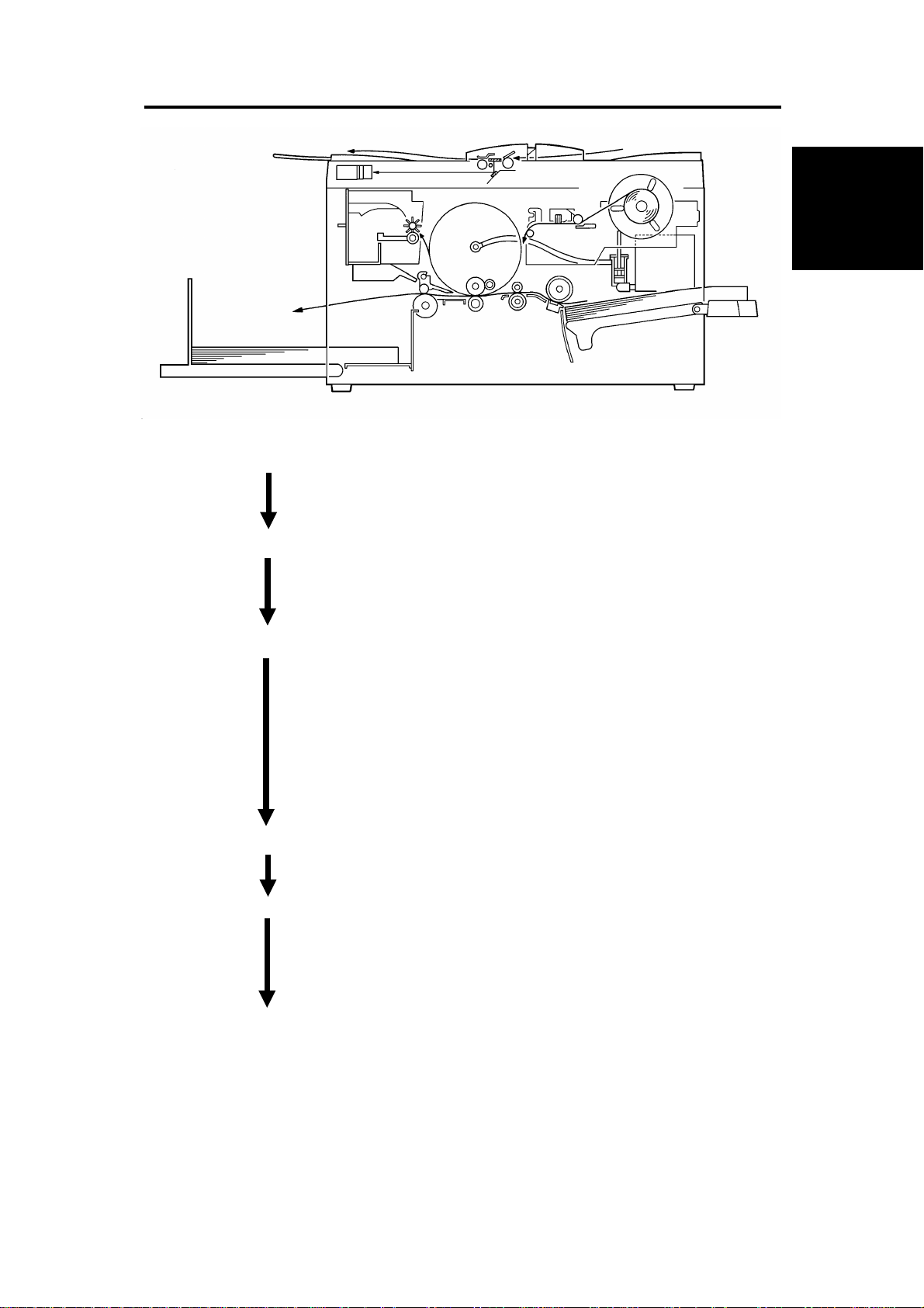
2. PRINTING PROCESS
1
6
1. Master Ejection: Removes the master from the drum and
ejects the used master into the master
eject box.
2. Scanning: Scans the original image through the
mirror and the lens to the CCD while
feeding the original.
3. Master Feeding: Converts the scanned CCD image signals
into digital signals which are used by the
thermal head to develop the master. The
generated heat de vel o ps th e m ast er by
atomizing the pla s tic coa ti n g It i s the n
clamped and wrapped around the drum
surface. The master is cut to cover the
entire drum surface.
4. Paper Feeding: Sends paper to the drum section.
2
3
Overall
Machine
Information
5
4
5. Printing: Presses th e paper fed from the paper
feed section onto the drum. This transfers
the ink to the paper through the drum
screen and the master.
6. Paper Delivering: The air knife and exit pawls removes the
printed paper from the drum, and ejects
the paper onto the pa pe r deli very table.
SM 1-3 C217
Page 26
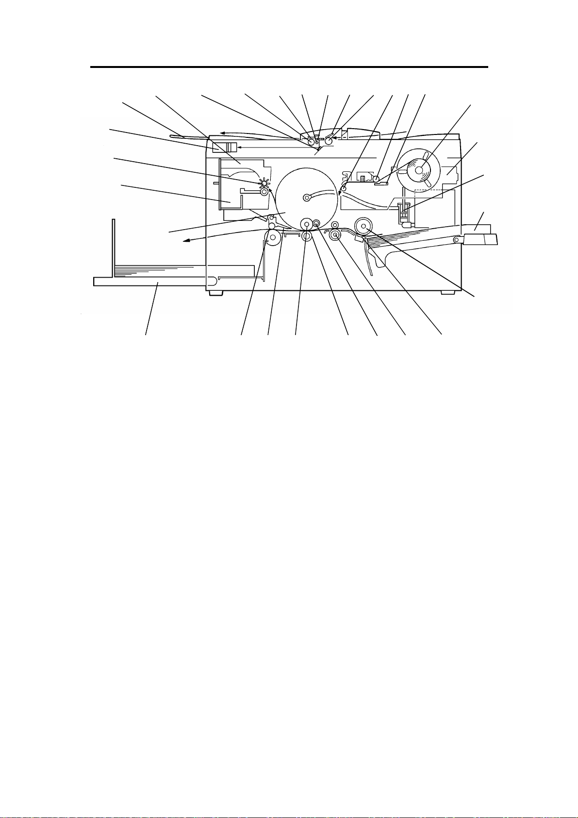
3. MECHANICAL COMPONENT LAYOUT
28
27
26
25
29
24
1234
5
6789
10
11
12
13
14
15
1617181920212223
1. Mirror
2. Original Feed Roller
3. Original Pressur e Pl at e
4. Exposure Lamp
5. Exposure Glass
6. Original Friction Pad
7. Original Pick-up Roller
8 . Master Tens ion Roller
9 . Plo tter Roller
10. Thermal Head
11. Master Roll
12. Plotter Unit
13. Ink Pump
14. Paper Table
15. Paper Feed Roller
16. Friction Pad
17. 2nd Feed Roller
18. Doctor Roller
19. Press Roller
20. Ink Roller
21. Exit Pawl
22. Exit Rollers
23. Paper Delivery Table
24. Drum
25. Master Eject Box
26. Master Eject Roller
27. CCD Unit
28. Original Exit Tray
29. Master Eject Unit
C217 1-4 SM
Page 27
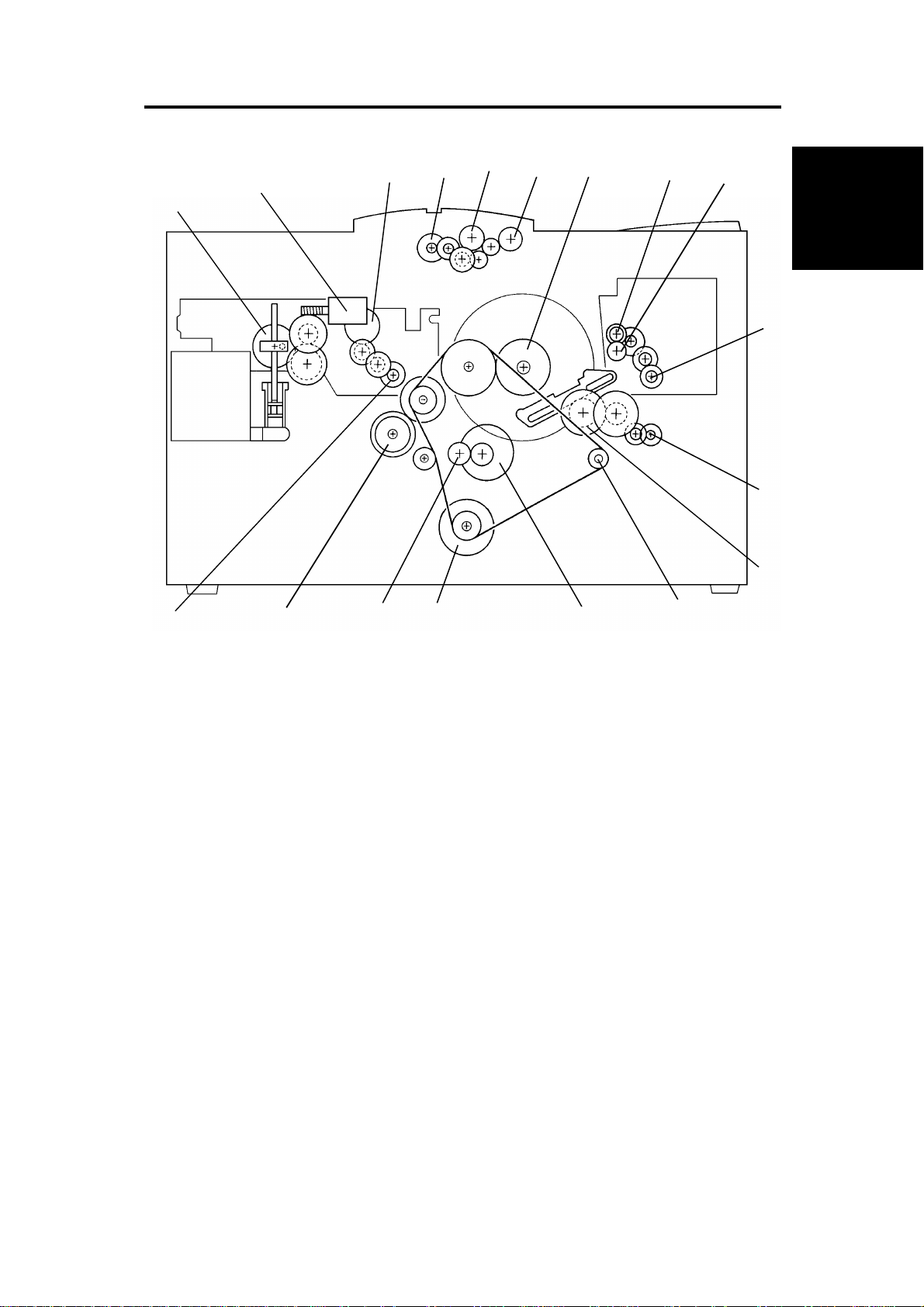
4. DRIVE LAYOUT
2
1
5
3
4
6
7
8
9
Overall
Machine
Information
10
11
18
1 . Pump Drive Gear
2. Ink Supply Motor
3. Platen Roller Gear
4. Original Feed Motor
5. Original Pick-up Roller
6. Original Feed Roller
7 . Drum Drive Gear
8. Upper Master Eject Roller Gear
17
16
15
10. Master Eject Motor
11. Master Clamper Motor
12. Master Clamper Drive Gear
13. Exit Roller Pulley
14. 2nd Feed Motor
15. Main Motor
16. 2nd Feed Roller Gear
17. Paper Feed Roller Gear
14
12
13
9 . Lo wer Master Eject Roller Gear
SM 1-5 C217
18. Master Feed Motor
Page 28

5. ELECTRICAL COMPONENT DESCRIPTION
P to P
Index No. Name Function
Motors
11
24
27
30
33
36
38
43
44
47
Solenoid
29
Sensors
1
3
13
14
15
16
17
18
25
28
31
35
37
46
Switches
5
6
9
20
21
22
26
Master Feed Feeds the master to the drum.
Pressure Plate Drives the pressure plate.
Main Drives paper feed, drum, printing and paper
delivery unit components.
2nd Feed Drives the 2nd feed roller.
Master Clamper Open and closes the master clamper.
Air Knife Rotates the fan to separate the paper from
the drum.
Master Eject Sends used master into the master eject box.
Original Feed Transports the original for scanning.
Master Cutter Cuts the master.
Ink Supply Drives ink pump to supply ink.
Pressure Release
Solenoid
Master End Detects if the plotter unit runs out of master
Original Registration
(Upper: light receiver,
Lower: light emitter)
Feed Jam Timing Determines the paper misfeed check timing.
Paper End Detects if the paper is set on the paper table.
Registration Detects misfeeds. In 2nd feed roller area .
Feed Start Timing Determines the paper feed start timing.
Exit Jam Timing Determines the paper misfeed check timing.
Master Eject Position Detects master eject position of the drum.
Drum Master Detects if the master is on the drum.
Exit Detects paper misfeeds.
Master Eject Detects used master misfeeds.
Full Master Detects if the master eject box is full.
Pressure Plate H.P. Detects the pressure plate home position.
Original Set Detects if the original is set on the original
ADF Open Check if the ADF is open.
Left Cutter Determines the left limit position of the cutter.
Master Cut Starts the cutter motor to cut the master.
Scanner Unit Open Checks if the scanner unit is open.
Delivery Cover Open Checks if the delivery cover is open.
Main Turns the power on or off.
Master Eject Box Checks if the master eject box is set
Releases the press roller to apply printing
pressure.
roll.
Informs the CPU of the original position.
Also, detects original misfeed.
table.
correctly.
Location
F-5
F-6
F-2
B-7
B-7
B-7
F-6
A-3
F-4
B-6
B-6
F-4
A-2
A-3
F-7
F-7
F-7
F-7
F-8
F-7
F-8
F-8
F-6
F-6
F-6
A-3
A-3
F-5
F-5
F-1
F-1
B-1
F-1
C217 1-6 SM
Page 29

Index No. Name Function
P to P
Location
34
45
Printed Circuit Board
4
8
12
19
23
32
39
40
Counters
7
10
Others
2
41
42
Master Clamper Detects the master clamper open/close
Right Cutter Determines the right limit position of the
Lamp Control Controls the power to the exposure lamp.
Operation Panel Interfaces the CPU and the operator.
Main Controls all machine functions.
Power Supply Provides power for all DC components.
Main Motor Control Controls the main motor speed.
Noise Filter Filters electrical noise on the AC power input
CCD Converts light intensity into an electrical
A/D Conversion Converts the analog signals into digital
Print Keeps track of the total number of prints
Master Keeps track of the total number of masters
Thermal Head Plots the master using heat.
Paper Feed Clutch Transmits the main motor drive to the paper
Exposure Lamp Applies light to the original for exposure.
position.
cutter.
lines.
signal.
signals.
made.
made.
feed roller at an appropriate timing.
F-8
F-5
A-2
B-5
C-5
D-1
F-2
A-1
A-5
A-4
F-5
F-5
E-2
B-6
A-2
Overall
Machine
Information
SM 1-7 C217
Page 30
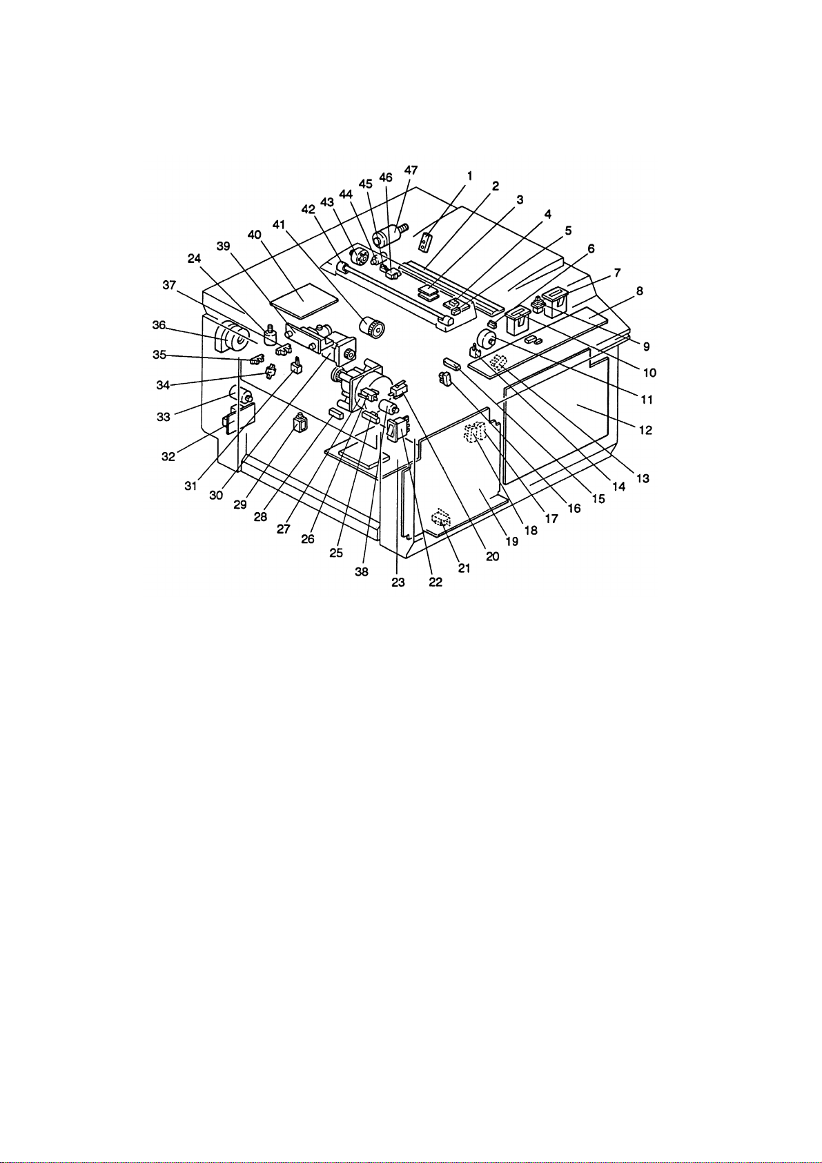
ELECTRICAL COMPONENT LAYOUT
C217 1-8 SM
Page 31

SM 1-9 C217
CCD PCB A/D Conversion PCB
A/D
Convert
Gate
Array
Exposure
Lamp
Lamp Control
PCB
Operation
Panel
Main PCB
Binary Processing Circuit
EPROM
Feed Control
RAM RAM
Gate
Array
Panel
Controller
EPROM
Main Control
I/O I/O
CPU
Thermal Head Drive
EPROM
I/O
Programable
Counter
Programable
Counter
RAM
RAM RAM
Gate
Array
Thermal Head
+20V
+5V, +/-12V, +24V,
+38V
+5V, +12V,
+38V
AC POWER
(120V or 220V)
Noise Filter
PCB
Main Switch
Power
Supply
PCB
6. OVERALL MACHINE CONTROL
Sensors
Switches
This diagram shows the control system
of the machine.
EPROM
Programable
Counter
Motor
Controller
2nd Feed Motor
CPU
Driver
Solenoid
Clutch
M M
Motors
Counters
EPROM
Motor
Controller
Main Motor
Control PCB
Main Motor
CPU
Driver
Overall
Machine
Information
Page 32

Page 33

DETAILED SECTION
DESCRIPTIONS
Page 34

Page 35

1. MASTER EJECT
1.1 OVERALL
[B]
[A]
[C]
At the end of the printing cycle, th e use d mast er rema ins wrap pe d aro und
the drum to prevent the ink on the drum surface from drying. When the
Master Making key is pressed to make a new master, the used master is
removed from the dr u m.
The machine checks if the drum is at the master eject position and if the
master is on the drum by the drum master sensor. The master clamper [A]
then opens to eject th e m ast er. If there is no master on the drum, th e
machine skips the master ej e ct op er a tio n and starts the master making
process.
The master eject rolle r s [B] turn for 0.5 seconds to pick up the leading edg e
of the used master. Aft er closi n g th e m ast er cl am p er, the dr um sta r ts r ot at ing
in the slowest speed (30 rpm). At the same time the master eject rolle rs turn
and feed the used master i nt o th e m ast er ej e ct bo x [C ].
Detailed
Section
Descriptions
When the drum stops at the master feed position after one and a half turns,
the pressure plate drive motor starts turning to compress th e used master in
the master eject box.
SM 2-1 C217
Page 36

1.2 MASTER CLAMPER OPEN MECHANISM
[B]
[J]
[E]
[J]
[K]
[G]
When the Master Making key is pressed the master eject position sensor [A]
is used to confirm that the drum is positioned at the master eject position
Normally, the drum is stop pe d at thi s po si tio n after every print job. If the
drum is not at this position, the machine first moves the drum to the master
eject position befor e ope nin g th e m ast er cl am p er.
[F]
[K]
[E]
[H]
[A]
[D]
[C]
The drum is moved to the eject position and locked usin g a "V" shaped notch
on the rear of the drum positioning guide [J] to locate and lock the drum
positioning stud [K] . A second stud, 180 degrees from the fir st, is use d to
position the drum du r ing ma ste r fee di n g op er a tions.
The master clamper ha s two spr in gs [B ] an d a m ag net pla te [C ] to secure
the master’s leading edge in the clamper. The clamper is fixed on the
clamper shaft [D] which has a lever [E] at the rear side.
The clamper motor [F] dri ves th e movi n g li nk [G ] an d pu she s up th e clam p er
lever [E].
The master clamper th en lif ts th e m ast er ej e ct ar m [H ] to r ele ase the
master’s leading edge from the clamper.
C217 2-2 SM
Page 37

1.3 MASTER EJECT ROLLER MECHANISM
[B]
[C]
Detailed
Section
Descriptions
[A]
The master eject roll e rs are dr iv e n by th e master eject motor [A] through id le
gears. The upper eject roller [B] has paddles to assure that the master is
picked up.
When the master clamper is ope ned and the master’s leading edge is
released from the master clamper, the master eject motor turns on for 0.5
seconds to pick up the leading edge of the used master.
When the master eject motor is turned off, the master clamper motor turns in
reverse direction to close the master clamper.
The drum then starts tur nin g at the slow est spee d (30 rp m) . At the same
time, the master eject rollers turn again to feed the master into the master
eject box.
After one turn of the drum, the master eject motor stops. The drum continues
turning for a half tu r n an d sto ps at the maste r fee d po siti o n.
The master eject sensor [C] is used to detect master eject jams.
SM 2-3 C217
Page 38

1.4 PRESSURE PLATE MECHANISM
[A]
[B]
[C]
[D]
[D]
[F]
[E]
[E]
[B]
[E]
The pressure plate m ot or [A ] dr ives the pressure plate [E] thro ug h th e dri ve
arm [B] and the pressure springs [C].
When the master has bee n ejected into the master eject box, the pressure
plate motor turns on and remains on until the full master detection sensor [D]
is actuated by the actua to r tab on th e pressure plate [E]. When the full
master sensor is actuated, the motor stops. When master making and
cutting are completed, the motor turns in the reverse direction to return the
pressure plate to the home position. When the pressure plate home position
sensor [F] is actuated, the motor stops.
If the full master senso r is not actuated within 2.4 seconds after the pressure
plate motor is activated, the machine stops the motor. The Empty Master
Eject Box indicator blinks after the master making procedure has finished
and the drum is positi on ed at th e mast er exi t posit i on (d rum ho m e posi ti o n).
C217 2-4 SM
Page 39

2. SCANNER AND OPTICS SECTION
2.1 OVERALL
[B]
[C]
[E]
[F]
[A]
[G]
A/D Conversion
PCB
Main PCB
Operation Panel
PCB
[H]
Thermal
Head
[D]
[J]
The first original at the bottom of the stack on the original table is separated
from the other originals by the original pick-up roller [A] and the original
friction pad [B], and is fed across the exposure glass [C]. The scanning starts
when the original is transported 5mm from the scan line. The master plotting
is synchronized with the original feeding.
Detailed
Section
Descriptions
The light of the exposure lamp [D] is reflected from the original and reflects
off the mirror through the lens [F] to the CCD [E]. The reflector [G]
compensates for shadows from the edge s of cut - and-p ast e orig ina ls. A
shading plate [H] installed between the mirror and the lens cuts some of the
light to correct for uneven light intensity between the center and both ends of
the lamp.
The light is changed to an electrical signal in each element of the CCD. The
analog signals from the CCD are converted into 4-bit digital data signals in
the A/D (analog\digital) conversion PCB and sent to the main PCB in which
each 4-bit digital data is converted into 1-bit data. The main PCB holds the
1-bit data for each pixel. The PCB uses the 1-bit data to turn on the thermal
head which will burn each pixel onto the master.
SM 2-5 C217
Page 40

2.2 ORIGINAL FEED MECHANISM
[D]
34 mm
[B]
13 mm
[C]
[A]
The originals on the original table are detected by the original set sensor [A].
A photo-transistor [B] in the upper position and an LED [C] in the lower
position make-up the original registration sensor.
After the master on the drum i s ejected to the master eject box, the or ig i na l
feed motor (stepper motor) starts rotating to feed the original to the exposure
glass [D]. When the original is transported 13 mm past the original
registration senso r , th e or ig i na l fee d mot or sto ps. At th i s tim e th e or ig i nal
leading edge is aligned with the CCD scan line on the exposure glass. Then
the original feed motor starts again synchronizing with the master feed.
The original pick-up roller keeps turning after the original trailing edge
passes the roller, so if a 2nd original is present, it will be fed directly after the
trailing edge of the 1st original.
After the 1st originals trailing edge is detected and transported 12 mm past
the original registration sensor, the original set sensor checks whether the
next original is present. If no original is detected, after the original trailing
edge passes the original registration sensor, the original is transported
further 35 mm (34+1) and fed out. If the next original is detected, the
originals are transported 1 mm further to ali g n th e 2nd original leading edge
with the scan line (the 2nd original has been transported a total of 13 mm
from the original registration sensor), then the original feed motor stops.
After printing of the 1st original is completed, the original transport motor
starts again for the nex t original.
C217 2-6 SM
Page 41

2.3 ORIGINAL FEED DRIVE MECHANISM
[D]
[A]
[B]
[C]
Detailed
Section
Descriptions
The pick-up roller [C] and the original feed roller [B] are driven through gears
by the original feed motor [A] (stepper motor).
The original feed roller [B] diameter is a little bit larger than the original
pick-up roller [C], so that a small gap is made between the continuous
originals while being transported. A one-way clutch is installed in the pick-up
roller gear [D] to ab sor b the spee d di f fe r en ce be tw e en the pick- up ro l ler an d
the original transport roller.
SM 2-7 C217
Page 42

3. MASTER FEED
3.1 OVERALL
[C]
[A]
[B]
[E]
[D]
The master materia l is fe d by th e pl a te n rol le r [A] acr oss th e th er ma l head
[B]. When the dru m is at the ma ste r fee d posi ti o n an d th e mast er cl amper is
opened, the tension roller [C] is released by the master clamper so that the
master’s leading edge is fed into the master clamper [D]. The leading edge
of the master is clampe d by th e m ast er clam p er , and the maste r is wr ap pe d
completely around the drum surface and then is cut by the cutter [E].
The drum is moved to the eject position and locked usin g a "V" shaped notch
on the rear of the drum positioning guide [J] to locate and lock the drum
positioning stud [K] . A second stud, 180 degrees from the fir st, is use d to
position the drum du r ing ma ste r fee di n g op er a tions.
C217 2-8 SM
Page 43

3.2 MASTER FEED MECHANISM
[B]
[D]
[C]
Detailed
Section
Descriptions
[F]
[E]
[A]
A stepper motor is used for the master feed motor [A] to drive the platen
roller [B]. The thermal head is pressed against the platen roller by the
pressure springs. The pressure can be released by the pressure release
lever [C] for master roll replenishment.
After the master eject procedure is finished, the dr um i s stopped at the
master feed position and the master clamper is opened for the new master.
The master’s leadin g ed ge is sto pp ed on th e gu ide pl at e [D ] aft er th e l ast
master cutting proce du re or af te r the maste r is cut manu al . The m ast er i s fed
for 23 mm and stopped once to synchronize with the original feed. The
master is fed for a further 67.5 mm before the master clamper is closed.
Since the clamper closin g timing is later than when the master’s leading
edge reaches the clampe r , a master buckle [E] is made on the master fe ed
guide. This master buckle absorbs the shock wave from the master clamping
operation.
The drum then turns intermittently in the slowest mode (30 rpm) to wrap the
master around the drum. The intermittent rotation keeps the master buckle
on the master feed guide to absorb the shock wave from the wrapping
operation. The tension roller [F] is pressed to the guide plate which gives the
tension to the master during the master wrapping operation.
SM 2-9 C217
Page 44

3.3 MASTER CLAMPER OPERATION AND TENSION ROLLER
RELEASE MECHANISM
[B]
[C]
[A]
[D]
[C]
[E]
When the master eject is completed, the drum is stopped at the master feed
position. At this time, the clamper motor [A] drive s the moving link [B] to
open the master clamp er [C ] .
The friction roller [D] is normally pressed against the master feed guide plate
to give tension to the master during the master wrapping operation. When
the clamper is opened, the clamper pushes the friction roller arms [E] and
releases the friction roller from the guide plate to allow the master to be fed
into the master clamper.
To close the master clamper, the clamper motor turns in the reverse
direction.
C217 2-10 SM
Page 45

3.4 CUTTER MECHANISM
[A]
[D]
[H][G]
[E]
[I]
Detailed
Section
Descriptions
[B]
[C]
[F]
After the master maki n g pro cess i s fi nish ed , th e m ast er fe ed moto r turn s off
and the cutter motor [A] starts turning.
The cutter motor drives the pulley [B] and the timing belt [C]. The cutter
holder [D] is mounted on the timing belt and has a switch actuator [E] at
each end.
The cutter mechanism is bi-directional. As the cutter travels in one direction
the master will be cut. During the next cutting operation, the cutter will travel
in the opposite direction.
There are two cutter position switches one at the front [F] and one at the rear
[G] of the cutter rail. When the cutter holder actuates one of these switches
at the end of cutter holder drive operation, the cutt er m ot or is turned off.
The inner roller [H] on the shaft of the rotary cutter blade [I] is touching the
cutter rail, so that the cutter blade is rotating while the cutter holder is moving.
After the master cut operation, the drum starts turning again to wrap the
remaining part of the master around the drum. At the same time, the mas ter
is fed another 32. 6 mm read y f or th e ne xt m ast er maki n g.
SM 2-11 C217
Page 46

4. PAPER FEED SECTION
4.1 OVERALL
[C]
[B]
[A]
The sheet of paper on th e pa pe r fee d ta bl e is sep ara ted by the paper feed
roller [A] and th e fr ic t i on pad [B] , an d tr a nsp or t ed to th e 2nd feed rollers [C].
The upper and lower 2nd feed rollers transport the sheet to the drum.
The paper feed roll e r is dri ven by the main motor, and an inde pe nd en t
stepper motor is used to control the 2nd feed rollers. The 2nd feed rollers
synchronize the paper feed timing with the image on the drum.
After the paper has come into contact with the 2nd feed rollers and the paper
is corrected for skew, the rollers will start rotating.
C217 2-12 SM
Page 47

4.2 PAPER FEED ROLLER MECHANISM
[C]
Detailed
Section
Descriptions
[D]
[A]
[E]
[B]
The paper feed roll e r [ A] is dri ven by the main motor [B] throug h ge ar s an d a
timing belt.
During the printing cycle, when the feed start timing sensor [C] is actuated by
the actuator on the drum, the electromagnetic clutch [D] is energized to
transmit the main motor rotation to the paper feed roller shaft. The top sheet
of paper is separated from the paper stack by the friction between the feed
roller [A] and th e fr ic t i on pad [E] , an d i s tr an spo r te d to t he 2nd f ee d rol le r .
A one-way clutch is installed in the paper feed roller so that after the
electromagnet ic clu tch is de- en erg i zed , i t do es no t di st ur b paper
transportation.
SM 2-13 C217
Page 48

4.3 2ND FEED ROLLER MECHANISM
[A]
[B]
The lower 2nd feed roller [A] is driven by a stepper motor [B]. The main PCB
controls the 2nd feed roller start timing to synchronize the image on the drum
master and the printing paper.
The stepper motor rot at i on spee d is chan ge d acco rdi n g to the pri nt i ng
speed. Also, by pressing the image position keys on the operation panel, the
2nd feed timing is chan ge d. If the paper feed timing is delayed , the image is
shifted forward (smaller lead edge margin). If the paper feed timing is
advanced, the image is shifted backward (large lead edge margin).
After the prin tin g pa pe r is cau gh t be tw e en the dr um an d th e pr e ss rol l er, the
feed roller stepper motor stops.
C217 2-14 SM
Page 49

4.4 UPPER 2ND FEED ROLLER RELEASE MECHANISM
[D]
[A]
Detailed
Section
Descriptions
[C]
[B]
When the feed rolle r step pe r motor stops, the upper 2nd feed rolle r is
released from the lower 2nd feed roller. This is to prevent interference of the
2nd feed roller s wh il e th e pa pe r is transported by the drum and the pr e ss
roller.
When the cam follower [A] reaches the top of the cam [B] which is installed
on the drum drive gear, the shaft [C] rotates clockwise (as seen from the
operation side) to release the upper 2nd feed roller [D] from the lower 2nd
feed roller.
If no image shifti ng mode is use d ( th e i mag e po si ti o n ind i cat or is at th e "0 "
position), the up pe r 2nd fee d r oll e r is rel e ase d whe n th e pa pe r is tr a nsp orted
30mm after reaching the press roller. Even if the paper feed timing is fully
delayed (Max. 15 mm), the paper leading edge reaches to the press roller
before the upper 2nd feed roller is released.
SM 2-15 C217
Page 50

4.5 PRINTING PRESSURE MECHANISM
[I]
[E]
[D]
[H]
[F]
[G]
[B]
[C]
[A]
While the machine is not in the printing cycle, the solen oid [A] stays of f an d
the stoppers [B] lock the brackets [C] to keep the press roller [D] away from
the drum.
When the 1st sheet of paper is fed, the solenoid is energized but the
brackets are still locked by the stoppers due to strong tension of the springs
[E]. When the cam fol low e r s [F], mounted on both sides of the press roll er
shaft, reach the top of the cams [G] on the front and rear drum flanges, a
small clearance is made between the stoppers an d the brackets. They are
then released from the brackets. Printing pressure is applied by tension of
the springs when the cam foll o wer s r eac h th e bo tt om of the cams .
During the printing cycle, the solenoid stays on. However, if paper does not
reach the registrat i on senso r [H] at the proper timing (at this time, the cam
follower is on the top of the cam), the solenoid is de-energized to lock the
brackets.
The printing pressur e is rel e ase d whe n th e cam s pu sh do w n th e cam
followers so that the press roller does not contact the master clamper [I].
C217 2-16 SM
Page 51

After printin g i s fi nish ed , the solenoid is de-energized an d th e stoppers
return by tension of the springs. Before the drum returns to the home
position, the bra cket is locke d by th e sto pp er ag ai n when the cams push
down the cam followers.
Detailed
Section
Descriptions
SM 2-17 C217
Page 52

4.6 PAPER TABLE
[H]
[A]
[G]
[F]
[E]
[C]
[D]
Paper on the paper table is lifted up to contact with the paper feed roller by
two springs [A]. When the lever [B] is lowered, the bearing [C] lifts up the
arm [D] to rotate the shaft [E] counterclockwise. The bracket [F] pushes
down the stay [G] and the paper table is lowered. The arm [D] hooks the
bearing [C] to stop the table in the lower position to allow easy paper setting.
A photo-interr u pter [H] is installed under the pap er table to detect paper on
the table.
[B]
[D]
[C]
[B]
C217 2-18 SM
Page 53

Section
Detailed
Descriptions
[A]
[B]
The paper feed roller pressure can be channeled by changing the position of
the pressure adjustment levers [A]. Normally the levers should be in the
upper position. If paper pick-up jams occurs frequently, the levers should be
lowered to increase the pressure.
If paper multif ee d occu r s f req ue ntly, the side pads [B] should be insta l l ed t o
apply stopping pre ssure to th e pa pe r .
SM 2-19 C217
Page 54

4.7 SIDE FENCE SLIDE MECHANISM
[D]
[A]
[E]
[B]
[C]
The paper table side fen c es [A ] are installed on the shaft [B]. When th e leve r
[C] is pinched, the stopper [D] is released from the shaft and either fence can
be moved independently. By turning the dial [E], the shaft and the side
fences move together side to side changing the paper position on the paper
table. If the dial is turned clockwise, the fences move to the left.
C217 2-20 SM
Page 55

5. DRUM
5.1 OVERALL
[B]
[C]
[D]
[A]
[F]
Detailed
Section
Descriptions
[E]
The drum consists of a met al scr ee n [A ] an d a cl ot h scr ee n [B ].
The ink pump supplies ink fr om th e i nk cartridge into the drum through the
drum shaft [C]. Ink is then spread evenly to the screens by the ink roller [D]
and doctor [E] roller. The developed master [F] with the plastic coatin g
removed from the image area allows the ink to flow through the exposed
porous material.
The drum is driven by the main motor and turns only clockwise (from the
operator side). The motor speed and the drum stop positions are controlled
by monitoring the main motor encoder.
SM 2-21 C217
Page 56

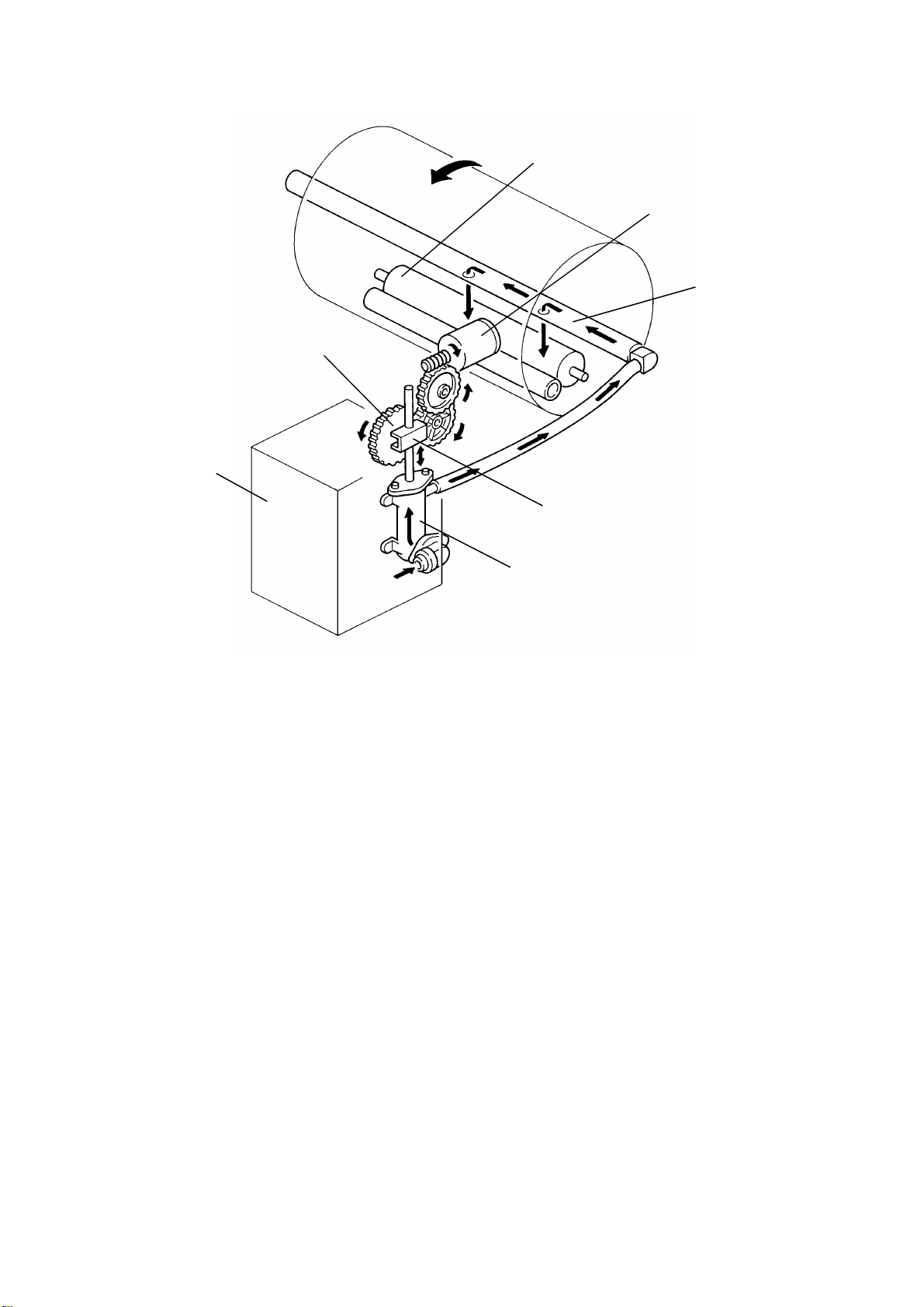
5.2 DRUM DRIVE MECHANISM
[D]
[A]
[C]
[B]
The drum is driven by the main motor (DC motor) through a timing belt [A]
and gears [B]. The main motor has an encoder which sends pulses to the
main PCB. The main PC B mo nitors the pulses and controls the dr um spe ed
and stop positions.
The drum has two stop positions as follows:
1) Master eject position/ Home position
2) Master feed position
These stop positions are determined by checking the feed start timing
sensor [C]. The main PCB sta r ts cou nt i ng the mai n mot or en cod er pu l ses
when the feed start timing sensor is actuated. The followin g pulse count
numbers are assigned for drum stop timing.
1) 440 pulses for the maste r ej ect position
2) 64 pulses for the master feed position
When the drum is stopped at the master eject position, the master eject
position sensor [D] is actuated. When the master eject operation is started,
the main PCB confir ms if the dr um i s at th e m ast er ej e ct po si tio n by th i s
sensor [D].
C217 2-22 SM
Page 57

5.3 MAIN MOTOR CONTROL
Detailed
Section
Descriptions
The main motor is driven by the main motor control PCB. The main PCB
sends the speed signals ( 0 an d 1), the main motor ON trigger, an d th e m ot or
brake trigger to the main motor control PCB. According to the combination of
two speed signals, the main motor control PCB can select on to of four
possible main motor speeds.
The main motor speed is converted in half for the drum rotation by the gears
and timing belt. The drum rotate s at 30rpm while the main motor rotates at
60rpm. This lowest possible speed also is used for the master eject and feed
operations. For th e m ast er w r ap pin g pr o cess, the ma in PC B send s the mai n
motor ON trigger as a pulse signal. As a result, the drum turns intermittently
at 30rpm.
The main motor speed is maintained by the main motor control PCB which is
monitoring th e en cod er pulses from the main motor.
CN108-4 (Speed 1) L L H H
CN108-5 (Speed 0) L H L H
Motor Speed 60 rpm 140 rpm 200 rpm 260 rpm
Drum Speed 30 rpm 70 rpm 100 rpm 130 rpm
SM 2-23 C217
Page 58
5.4 INK SUPPLY MECHANISM
[E]
[A]
[B]
[D]
[G]
[F]
[C]
Ink is supplied from th e ink car t r idg e [A ] to the ink ro ll er [B] by a pump [C].
The ink pump is driven by the ink supply motor (DC motor) [D] through
gears. There is a pin on the pump drive gear [E] which is coupled with the
pin holder [F] on the pump piston shaft. This mechanism converts the gear
rotating motion into the piston vertical alternatin g motion.
Two holes on the drum shaft [G] drop ink on to the ink roller [H].
C217 2-24 SM
Page 59

5.5 INK ROLLER MECHANISM
[C]
[B]
[A]
[D]
Detailed
Section
Descriptions
[E]
[F]
The ink roller [A] and the doctor roller [B] are driven by the gear [C] on the
drum shaft. Ink supplied on the ink roller is squeezed by the doctor roller and
an even thickness ink layer is applied to the ink roller. The ink drive gear [D]
has a one-way clutch to pre ven t th e ink r oll e r f rom tu r nin g in th e r eve rs e
direction when the drum is turne d in the reverse direction manually.
The ink roller only touches the screen [E] during printing. During the printing
process, the ink on the ink ro ll er i s app li ed to th e pa pe r thro ug h ho l es in th e
screens and master. This happens while the drum screen and the master
are held against th e i nk roll e r by the pressure roller [F] located under neath
the drum.
SM 2-25 C217
Page 60

5.6 INK SUPPLY CONTROL
[B]
[A]
[C]
[D]
The ink detection pins [A] work like the electrode of a capacitor and detect
the capacitan ce between the detection pins and the ink [B] and doctor [C]
rollers. This capaci ta nce is dif fe r en t whe n th e i nk leve l is hi g h and the pins
touch ink, compared to whe n th e ink l eve l is low an d th e pin s do not to uch
ink. By detecting the capacitance, the ink supply moto r is controlled to keep
the ink level.
The ink roller blade [D] is inst al le d on bot h en ds of the ink ro ll er to scra pe off
the built-up ink on the ink roller edges.
C217 2-26 SM
Page 61

[B]
Timer IC
1
OUT 1
TP102
5
2
[A]
TH1
VR101
12
TH2
OUT 2
+
+
TP102
TP103
(Sufficient Ink)
To
T1 T2
TP103
9
LED101
+
_
P
To
CPU
Main PCB
(Less Ink)
P
LED101 ON OFF
A timer IC is used to dete ct th e i nk leve l. The IC produces two pulse signals.
TP102 outputs the st an da r d pul se si gn al , the stan da r d pu l se l en gt h T0 is
determined by the VR101. TP103 outputs the detection pulse. This pulse
length is determined by the capacitance between the detection pins and ink
and doctor rollers.
M
Detailed
Section
Descriptions
(Sufficient ink condition)
When the ink level is high and the pins [A] are touching the ink, the
capacitance becomes large and increases the detection pulse length (T1).
When the detection pu lse length is longer than the standard pulse length
(T0<T1), "P" becomes low and turns on the LED101. While the CPU is
receiving the low si gn al at
, the CPU recognizes that ink level is sufficient
"P"
and does not turn on the ink supply motor [B].
(Less ink condition)
When the ink level is low, the capacitance is lowered and decreases the
pulse length (T2). When the detection pulse length is shorter than the
standard pulse len gt h ( T0> T2 ) , "P" becomes high and turns off the LED101.
While the CPU is re ceiv in g the high signal at "P", the CPU recognizes that
the ink level is low and turns on the ink supply motor to supply ink until the
signal at "P" becomes low.
SM 2-27 C217
Page 62

Rev. 10/20/93
(Ink End Condition)
If the less ink condition is detected contin uo usly fo r more then 25 second s
during the print cycle, the CPU stops the printing process and turns on the
Ink End indicator.
When printing starts in the less ink condition, the main motor keeps turning,
and turns on the ink supply motor turns on until the ink level returns to a
sufficient level. If the ink returns to a sufficient level within 25 seconds, the
machine starts the printing operation. If not, the machine lights the Ink End
indicator.
A beeper sounds intermittently while the machine is idling during the ink
supply.
The machine has a forced ink supply mode. When the Reset key is pressed
while holding down the "0" key, the machine starts the ink supply operation.
This operation continues for 50 seconds and stops automatically when ink
reaches a sufficient le vel. If ink is not neede d an d th e pr o cess w as
commenced it will proceed normally but the ink supply motor will not operate.
(To Disable Ink Detection Circuit)
The ink detection circuit can be disabled if the main switch is turned on while
both the Auto Cycle key and the Reset key are pressed. If this mode is
accessed, prints can be made even though the ink detection pin is not in
contact with the ink on the ink roller (see page 2-26 Ink Supply Control).
When the main switch is turned off, this condition is reset to normal
operation.
This function serves to remove the ink inside the drum.
C217 2-28 SM
Page 63

6. PAPER DELIVERY SECTION
6.1 OVERALL
[C]
[B]
[E]
[A]
[D]
Detailed
Section
Descriptions
The exit pawls [A] and the air knife [B] separate the paper from the drum.
The paper is deliver e d to the pap er delivery table [C] by the upper and lo w er
exit rollers [D].
There is a photore flector type photosensor mounted between exit roller
assemblies [E] to detect paper jams.
SM 2-29 C217
Page 64

6.2 PAPER DELIVERY ROLLER
[C]
[E]
[A]
[B]
The lower exit rolle r s [A] are driven by the main motor [B] thr o ug h th e ti m in g
belt. The upper exit rollers [C] and the lower exit rollers catch the paper and
transport it to the delivery table.
[A]
[D]
The lower exit roller are controlled by green plastic guide plates [D] which
are mounted to the exit pawl. This allows the upper and lower exit rollers to
move together.
Each roller position should be adjusted according to the paper position on
the paper table, so that the upper and lower exit rollers catch 5 mm inside of
the paper edge to transport it. The paper size indicator [E] shows the
standard deliver y rol le r posit i on for ea ch paper size.
C217 2-30 SM
Page 65

6.3 EXIT PAWL/AIR KNIFE
[F]
[D]
[E]
[C]
[B]
Detailed
Section
Descriptions
[A]
The air from the air knife nozzle [A] and the exit pawls [B] separate paper
from the drum.
The air knife motor starts blowing air when the print start key is pressed or
master cutting is completed. The paper passes under the exit pawls and is
caught by the exit rollers. The motor stops when the last sheet of paper is
fed out.
The upper exit rolle rs [ D] ar e insta l led on th e exit paw ls. They are pushed
against the lower exit rollers [E] by tension of the springs [F].
SM 2-31 C217
Page 66

6.4 EXIT PAWL RELEASE MECHANISM
[B]
[A]
[C]
[D]
[E]
The exit pawls [A] move away from the drum when the master clamper [B]
approaches the pawls. This is controlled by the cam [C] installed on the front
drum flange and the two cam followers [D and E] installed on the exit pawl
shaft. The two cams allow enough time to move the pawls away from the
drum.
While the cam followers are not on the top of the cam, the distance be tween
the pawls and the drum is very small to prevent paper wrap jams. At this
time, the distance is determined by the stopper, and the cam followers are
not in contact with the cam. However, when the master clamper approaches
the exit pawls, the pawls must be mov ed away from the drum to avoid
contact and damage against the master clamper. As the master clamper
approaches the exit pawls, the cam moves into contact with the cam follower
pushing them down. This rotates the cam follower arm, and the pawl shaft
clockwise, to move the pawl s awa y from th e dr u m. W he n bo th cam fol lo w ers
are out of contact with the cam, the pawls move back towards the drum to
their normal position.
C217 2-32 SM
Page 67

7. JAM DETECTION
7.1 ORIGINAL JAM DETECTION
[B]
13 mm
34 mm
[A]
Original jams are detected by the original set sensor [A] and the original
registration sensor [B]. The misfeed indicator ( + A) lights with the
following conditions:
1) When the main switch is turned on, if the original registration sensor
is interrupted.
Detailed
Section
Descriptions
2) When the original set sensor is actuated, if the original registration
sensor does not detect th e or i g ina l leading edge within 3 seconds
after the Master Making key is pressed.
3) If the original registration sensor does not detect the trailing edge of
the original within 4 seconds after the original leading edge is
transported 355.6 mm from the original registration sensor.
4) If the original stops interrupting the original registration sensor after
the stop key is pressed while scanning.
SM 2-33 C217
Page 68
7.2 MASTER EJECT JAM DETECTION
[A]
[B]
The master eject jams are detected by the master eject sensor [A]. The
misfeed indicator ( +F) lights in the following conditions:
1) If the master eject sensor is actuated when the main switch is turned
on.
2) If the master eject sensor is not actuated withi n 0.3 seconds after the
drum started turning to feed the master into the master eject box.
3) If the master eject sensor is not actuated when the drum makes a
half turn and passes the fe ed jam tim ing senso r [B] . Thi s is the case
when the picked up master leading edge is pulled back to the drum
and the master rema ins on the dr um. (The jam indicator lights afte r
the drum returns to the home position.)
4) If the master eject sensor is actuated when the pressure plate is
returned to the home po si tio n. Thi s is th e case when the maste r
trailing edge sticks on the pressure plate and is pulled back to the
master eject rolle rs .
C217 2-34 SM
Page 69

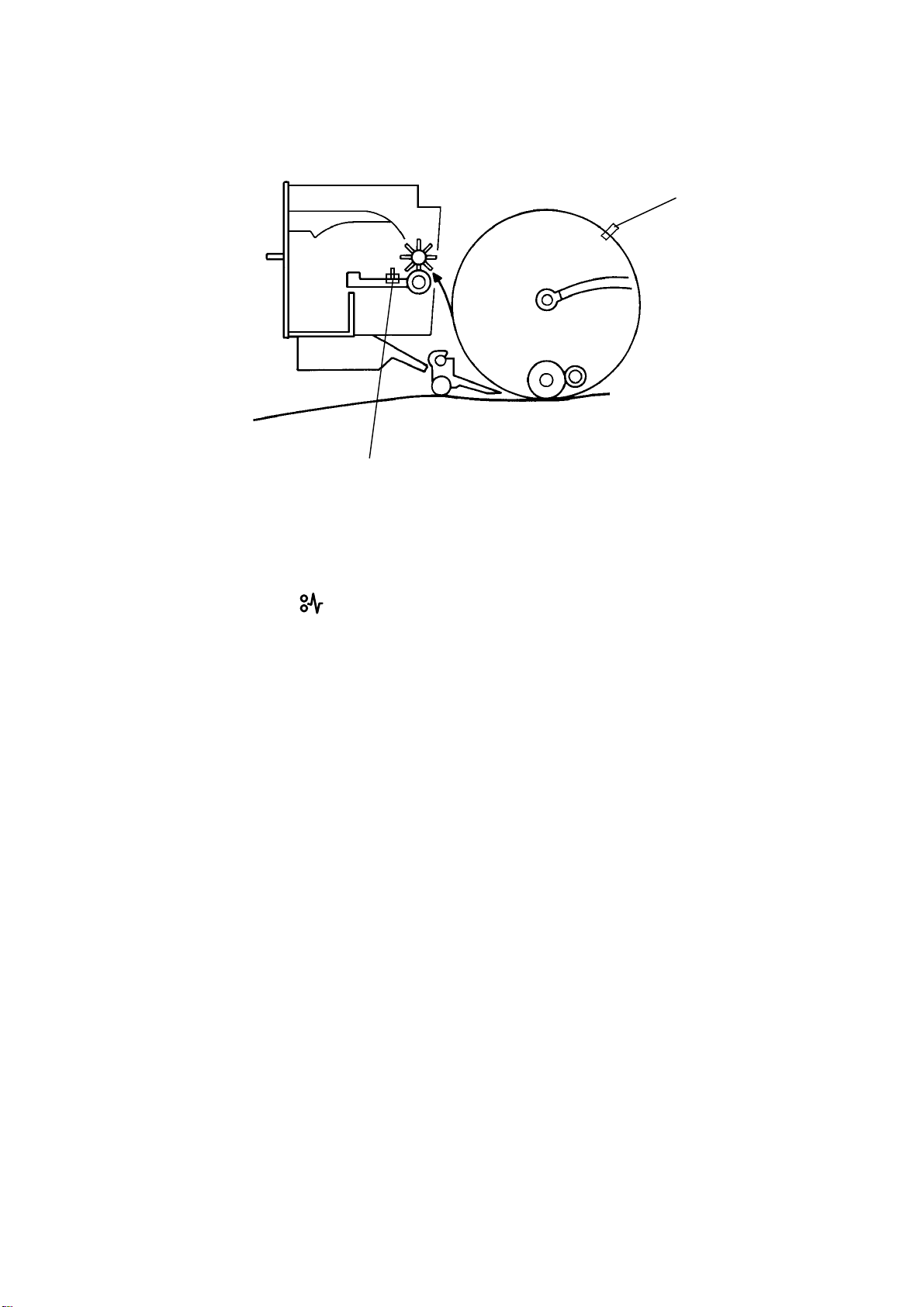
7.3 MASTER FEED JAM DETECTION
[B]
[C]
[A]
Detailed
Section
Descriptions
There is no master feed se nsor on the master paper feed path to detect
master feed jams. The mast er fe ed jam is de te cte d by th e dru m maste r
sensor [A] which detects the presence of a master on the drum.
When the drum is stopped at the master exit position prior to the start of
printing. After master making, if the master sensor [B] does not detect the
master on the drum, the master misfeed indication ( + C) will be displayed
on the operation panel. (The master eject position sensor [C] is used to
confirm that the drum is positioned at the master eject position.)
SM 2-35 C217
Page 70

7.4 PAPER FEED JAM DETECTION
[C]
[B]
[D]
Paper jams are detected by the registration sensor [A] and the exit sensor
[B]. Jam detection timing is determined by the drum position sensors and the
main motor encoder. The timing chart on the next page shows the jam
detection timing.
[E]
[A]
C217 2-36 SM
Page 71

NN
Feed Start
Timing Sensor
Feed Jam
Timing Sensor
t
Exit Jam
Timing Sensor
Registration
Sensor
a) ON Check
Exit Sensor
b) OFF Check
c) ON Check
c) B or E Jam Identification
a) When the CPU counts a determined number of pulses (N) from the
main motor after the feed start timing sensor [C] is actuated, if the
registration sens or do es no t de tect the paper, B + light.
Detailed
Section
Descriptions
b) When the exit jam timing sensor [D] is actuated, if the exit sensor
remains activated, G + light.
c) When the determined time (t) (th is time depends on the drum speed)
is counted after the exit jam timing sensor is actuated, if the exit
sensor is not activated, the machine detects a paper jam. If this jam
condition is detected, the main PCB stops the next paper from being
fed. When the feed jam timing sensor [E] is actuated:
1. If the registration senso r is act i vat ed , a 2n d fe ed fail u r e is
detected. (B + )
2. If the registration senso r is no t act i vat ed , a pa pe r wra p jam is
detected. (E + ).
SM 2-37 C217
Page 72

8. IMAGE PROCESSING
Image processing r eso l ves ho w to tra nsf or m an opt i cal i mage of a
continuous line, made up of an infinite number of color shades, into 2592
lined-up dots (pixels), each of which is black or white.
There are two basic sub-processes: first A/D conversion, i.e. con verting an
analog image to
binary processing, i.e. transforming that digital data into black or white pixels.
8.1 A/D CONVERSION
4-bit digital data
representing 16 shades of gray; second
CCD
(1) (2)
OS
DOS
Inversion &
Amplification
A/D Conversion
Parameter
(6)
Setting
Shading
Distortin
Correction
(3)
VB
VS
VH
M1
M2
M3
VL
Image mode/Image density
Setting
A/D
Converter
(7)
(4)
Peak
Hold
(5)
Black
Level
VPH
(8)
Shading
Distortion
Memory
4-bit Digital Data
Binary processing
Circuit
to
This block diagram shows the A/D conversion process (A/D= Analog to
Digital). The analog signal generated from the CCD is inverted and
amplified. Then the analog signal is converted into a 4-bit digital signal and is
sent to the binary pro cessi n g cir cui t .
The following sections (8.1.1 - 8.1.8) will give a brief explanation of the
various steps in the A/D conversion process.
C217 2-38 SM
Page 73

(1) CCD
The light reflected from the
original exposes the CCD
(Charge Coupled Device) which
OS
can read one complete scan line
at a time. The circuit of each
element in the CCD is shown at
the right. The CCD has 2592
effective elemen ts. The l igh t
reflected from the original is
sensed by a photodiod e. A
capacitor stores the electrical
charge corresponding to the
light’s intensity.
The electrical charges from the CCD elements are sent to the A/D
conversion PCB one after the other (OS signal).
The CCD always outputs a compensation data signal (DOS signal) with the
OS signal. This DOS signal is used for the inversion and amplification
described below.
Detailed
Section
Descriptions
(2) Inversion and Amplification
The CCD output is inverted and amplified.
To remove electrical no is e, the
difference
between the OS signal
and the DOS signal is amplified.
Even if electri cal no i se i nt r ud es
into the power source of the
CCD, it does not effect the
amplified signal, because the
noise affects both signals
identically. Ther ef or e ,
substracting the DO S sign al fr o m
Inverted &
Amplified
CCD Output
the OS signal will cancel the noise out.
The amplification ratio can be changed by turning VR201.
SM 2-39 C217
Page 74

(3) Shading Distortion Correction
The image data of one main scan line sent from the CCD does not exactly
represent the line of the original image, because of the followin g reasons:
1) Loss of brightness towards the ends of the fluores cent lamp and the
edge of the lens,
2) Variations in sensitivity among elements of the CCD,
3) Distortions of the light path.
These distortions are corre cted by applying individual amplification ratios (α)
to the output of each CCD element. The amplification ratio of each element
is determined so that all the CCD outputs are amplified to match the highest
voltage from the platen cover data when the white platen cover is scanned,.
When the main switch is tu rne d on , th e scan ne r scans th e w hit e pl a te n cove r
5 times. The white platen covers data which corresponds to each CCD
element is stored as 4-bit digital data in the shading distortion memory circuit
and used for the shadin g distortion correction.
Actual CCD output
when the white
Corrected output
A
platen cover is read
B
VB
Amplification ratio: α
A+B
α ≈
B
(4) Peak Hold (VPH)
Before the analog signal can be converted to digital data, the machine must
know the high and low bounds that match white and black. These bounds
are voltage values.
The low bound is called the bl ack leve l (VB, see pg. 2-41). The high bound is
called the peak hold value, or VPH.
When the analog signal is digitized, VB and VPH will serve as references to
determine how the CCD output will be distributed over the sixteen different
4-bit values.
C217 2-40 SM
Page 75

a) Peak Hold for the Shading Distortion Memory
When the main switch is tu rne d on , th e exp osu re l amp tur n s on and th e
white platen cover is scanned 5 times. The white peak value from the platen
cover scan is held in the peak ho l d cir cui t and used to de te r mi ne the
amplification ratio (α) of the shading distort i on memory.
b) Original Backgr o un d Pe ak H old
The peak hold from the platen cover scans is erased before original
scanning starts. After original scanning starts, this circuit holds the whitest
image voltage of the 43 mm (512 pixels) width in the middle of the scan line.
The highest value sens ed duri n g an or igi n al scan is cal le d the original
background peak hold. It does NOT always correspond to a pure white
original, but it will serve to establish the whitest part of the print image. In
other words it will turn a dark background white.
Once a peak hold is record ed, it does not change un til a higher (whiter)
value is scanned, or until the next original is scanned.
(5) Black level (VB)
This circuit always outputs 1.4V. This black level voltage is used as a
reference for A/D conversion and as the lower limit of the amplified CCD
output.
Detailed
Section
Descriptions
SM 2-41 C217
Page 76

(6) A/D Converter
The analog data VS (am p li fi e d
CCD outputs) is changed into
4-bit digital data. The 4 bits of
data represent a number between
0 and 15, for a total of 16 steps.
In the A/D conversion circuit, the
difference bet ween VH and VL
(see pg. 2-43) is di vi de d into 16
steps. Each step corresponds to
a VS voltage level.
VPH
VS
(Analog Data)
15
14
13
12
11
10
13
(Digital Data)
The digital data from the analog
image data (VS signal) is based
on these 16 steps.
For example, the amplified CCD
output (VS), whose level is as
shown at right, is changed into
"13" (digital data) to be sent to the
binary processing circuit.
VB (1.4 V)
PB (1.4 V)
9
8
7
6
5
4
3
2
1
0
A/D Converter
C217 2-42 SM
Page 77

(7) A/D Conversion Parameter Setting
Process
Shading Distortion Memory 100 86.5 73.0 59.5 46.0
Line Mode
Image
Setting
Photo
Mode
Parameter
Lighter 74.0 57.0 40.0 23.0 6.0
Normal 100 76.5 53.0 29.5 6.0
Darker 1 100 79.8 59.5 39.3 19.0
Darker 2 100 84.5 69.0 53.5 38.0
Lighter 70.0 36.6 19.6 11.4 7.0
Normal 80.0 43.4 24.8 15.8 11.0
Darker 1 85.0 47.9 29.0 19.9 15.0
Darker 2 92.0 52.3 32.0 22.3 17.0
The A/D conversion paramet er s
(VH, M1, M2, M3 and VL)
decide how the the VS signal is
distributed over 16 steps. The
parameters are determined
according to VPH, VB, the
image mode setting, and the
image density setting.
VH and VL are the upper and
lower image density bounds. If
a darker image setting is
selected, VH and VL incr ea se
(as shown at right). M1, M2 and
M3 are set to impro v e im ag e
quality in the phot o m od e.
The above table shows the
ratio of VPH (100 %) an d ea ch
parameter at various image
VH (%) M1 (%) M2 (%) M3 (%) VL (%)
VP = VH
M1
M2
M3
VL
15
14
13
12
11
10
9
8
7
6
5
4
3
2
1
0
VP
VH
M1
M2
M3
mode settings (deciding the VB
at 0%). The voltage between
each parameter is divided into
further 4 steps, thus th e vol t ag e
between VH and VL is divi d ed
into 16.
VB (1.4 V)
Image Mode,
Darker 2
VL
VB (1.4 V)
Image Mode,
Lighter
15
14
13
12
11
10
Section
Detailed
Descriptions
9
8
7
6
5
4
3
2
1
0
SM 2-43 C217
Page 78

Line Mode
Normal
Photo Mode
Normal
100%
VS
50%
F
100
76.5
53.0
29.5
6.0
VH
M1
M2
M3
VL
80
43.4
24.8
15.8
11.0
Graph 1
VH
M1
M2
M3
VL
0
0.5
1.0 1.5
Original Density
Graph 2
Line Mode, Normal
0
0.5
F
1.0
1.5
Original Density
Graph 3
Photo Mode, Normal
0
0.5 1.0 1.5
Original Density
As shown in Graph 1, the relationship between the original density and VS
(amplified CCD output) is not linear due to CCD characteristic.
C217 2-44 SM
Page 79

In the line mode, M1, M2 , an d M 3 are set so th at the di sta nce bet wee n ea ch
of them is equal, and the relationship between the original density and the
output digital data are as shown in graph 2.
In the photo mode, M1, M 2, and M3 are set so tha t th er e ar e mor e step s in
the darker area (low sensitivit y area). This improves the quality of the
gradation. (Refer to (3) Shading Distortion Correction.)
(8) Shading Distortion Memory
The amplificatio n r at i os ( α) which corresponds to each CCD elements are
stored as 4-bit dig ita l dat a i n the shading distortion memory ci r cuit and used
for the shading dist ortion correction.
Detailed
Section
Descriptions
SM 2-45 C217
Page 80

8.2 BINARY PROCESSING
Binary processing resolves how to transform a line of "gray" pixels (the 4-bit
digital data from A/D conversion) into a line of black and white pixels in such
a way as to preserve th e quality of the image.
The binary processin g cir cuit produces 1-bit data (white or bl a ck pixel s) fr o m
the 4-bit output of the A/D converter, and sends it, as a serial signal to the
thermal head dri ve ci r cui t . The binary process is different betwe en the lin e
mode and the photo mod e.
1) Line Mode: MTF (Modulation Transfer Function) Correction
2) Photo Mode: Dither Proces sing and Edge Emphasis Processing
(Edge Emphases Pro c essin g i s selected only when the DIP-SW 101-6 is
turned on.)
C217 2-46 SM
Page 81

8.2.1 MTF Correction
When the original image is converted to electrical signals by the CCD, the
contrast is reduced. This is becau s e ne igh bo r ing black an d w hite parts of the
image influence each oth er due to lens characteristics . This phenomenon is
typical when the width and spacing of the black and white areas are
narrower.
MTF correction counters this ph enomenon and emphasizes image detail.
The value of a target pixel is modified according to the value of surrounding
pixels. The modified data is compared to the threshold level. This determines
if the pixel is to be black or white.
Main Scan
IHG
Sub Scan
FED
CBA
Detailed
Section
Descriptions
E2 = 2E – 1/2(D + F) ------ Main Scan Data Modified
E1 = 2E – 1/2(B + H) ------ Sub Scan Data Modified
The modified data is compared to a threshold level to determine if the pixel is
black or white.
Modified Data E2 ≥ 8.0 or Data E1 ≥ 8.0 ----- Black
Modified Data E2 < 8.0 and Data E1 < 8.0 ----- White
SM 2-47 C217
Page 82

8.2.2 Dither Processing
A dither matrix is made of 4 x 4 pixels and contains 16 different threshold
levels for the locations which correspond to 16 pixels of the original image.
Each pixel data (En) from the A/D conversion circuit is compared with the
corresponding threshold level (Vthn) in the dither mat r ix. The n each pixe l
data is converted to eithe r bl ack or white depending on whether the image
data is greater or less than the threshold level.
En > Vthn.............. Black
En ≤ Vthn.............. White
Main Scan
5
5
5
5
5
5
Sub
Scan
5
5
5
5
5
5
5
5
5
5
5
5
5
5
5
5
5
5
5
5
5
5
5
5
5
5
5
5
5
5
5
5
5
5
5
5
5
5
5
5
5
5
5
5
5
5
5
5
5
5
4-bit pixel data to be read
Example: All pixel s ar e at 5.
5
5
5
4
5
5
5
5
5
4
7
14
8
4
7
14
1
0
9
2
5
11
14
14
9
11
14
12
10
13
4
7
1
0
2
5
12
10
13
0
9
3
5
11
6
13
14
7
14
8
0
9
3
5
11
6
13
14
4 x 4 dither matrix
Threshold level of the
dither matrix (number
shows each Vthn).
8
4
3
1
6
2
12
10
8
4
3
1
6
2
12
10
Image reappearance
(shaded pixels are
black, showing the
pixels with values
below the threshold )
8.2.3 Edge Emphasis Processing in the Photo Mode
In the photo mode, if characters are processed using the dither method, they
will be difficult to be read due to the distorting nature of the process. To
counter this, when the den s ity di f fe r en ce be tw e en a pixel an d sur rounding
pixels is greater than a specified level, the surrounding pixel data is
processed using MTF instead of the dither process.
C217 2-48 SM
Page 83

8.3 THERMAL HEAD
Detailed
Section
Descriptions
8.3.1 Thermal Head Control
The thermal head has heating elements at a density of 300 DPI. The thermal
heating elements melt the over-coating and polyes ter film layers of the
master according to the image signal for each pixel.
The Power Supply PCB applies power (VHD) to the thermal heating
elements. The power sou r ce varies from one head to anot her since the
average resistance of each element varies. Therefore, when the thermal
head or Power Supply PCB is replaced, it is necessary to readjust the
applied voltage with the particular value indicated for each thermal head.
The energy applied to the thermal heating elements is determined by the
length of time (t) at which power is applied.
SM 2-49 C217
Page 84

The time depends on the thermal head temperature which is detected by the
thermistor on the thermal head. If the temperature is higher, the time (t) will
be shorter.
Long
ENR
Pulse
Length
Short
High Low
The time(t) is determined when the Master Making key is pressed, and it is
kept until the master makin g is finished.
8.3.2 Thermal Head Protection
The thermistor on the the r m al he ad and a the r mal gu ar d (a the r m ost at ) on
the PSU are used for thermal head protection. This prevents the thermal
head and power supply unit from overheating when continuously processing
a solid image. The CPU detects the abnormal condition when the Master
Making key is pressed, and lights the SC code on the operation panel as
follows:
Detecting Comp on en t Conditions SC Code
Thermistor Over 54°C E – 04
Thermistor Under – 20°C (Thermistor open) E – 09
Thermal Guard Over 85°C E – 08
C217 2-50 SM
Page 85

9. MASTER PLOTTING AND PRINTING AREA
1. Length
14" (355.6 mm)
Original
Master Plotting Length
5 mm
Master
(349.6 mm)
Screen
Paper
(Shift : 0 mm)
Paper
(Shift : 15 mm)
9.2 mm
86.2 mm
Master Length (475 mm)
Screen Mesh Length
(382.4 mm)
Printing Pressure (385.2 mm)
Image Area Length (349.6 mm)
5 mm
(355.6 mm)
Image Area Length (339.6 mm)
6.4 mm
Detailed
Section
Descriptions
15 mm
Paper
(Shift : –15 mm )
SM 2-51 C217
5 mm
Image Area Length (335.6 mm)
15 mm
(355.6 mm)
(355.6 mm)
Page 86

2. Width
Original
Master
81/2" (215.9 mm)
Master Plotting Width
(210 mm)
15 mm
Master Width (240 mm)
5.925 mm
Screen
Paper
Screen Mesh Width
(220.5 mm)
Image Width (210 mm)
(215.9 mm)
C217 2-52 SM
Page 87

INSTALLATION
Page 88

Page 89

1. INSTALLATION REQUIREMENTS
The installation location should be carefully chosen because the
environmental conditions greatly affect the perf ormance of the machine.
1.1 OPTIMUM ENVIRONMENTAL CONDITION:
Temperature — 10 to 30°C
(50 to 86°F)
Humidity — 20 to 90 % RH
On a strong and level base.
Installation
The machine must be level within
5 mm (13/64") both front to rear
and left to right.
SM 3-1 C217
Page 90

1.2 ENVIRONMENTS TO AVOID:
Locations exposed to direct
sunlight or strong light (more than
1,500 lux).
Areas with corrosive gases. Locations directly exposed to cool air
Dusty areas.
from an air conditioner or reflected
heat from a space he ater. (Sudden
temperature changes from low to
high or vice versa may cause
condensation within the machine.)
C217 3-2 SM
Page 91

1.3 POWER CONNECTION:
Securely connect the power cord
to a power source.
Make sure that the wall outlet is
near the machine an d ea si l y
accessible.
Make sure the plug is firmly
inserted in the outlet.
Voltage must not fluctua te mo r e
than 10%.
Installation
Avoid multiwiring. Do not pinch the power cord.
SM 3-3 C217
Page 92

1.4 ACCESS TO MACHINE:
Place the machine ne ar a po w er source, providing clearance as shown
below.
10 cm (4.0")
Paper
Delivery
Table
More than
60 cm
(23.7")
105 cm (41.3")
Paper
Feed
Table
More than
60 cm
(23.7")
61 cm
(24.0")
More than
70 cm
(27.6")
C217 3-4 SM
Page 93

2. INSTALLATION PROCEDURE
Installation
1. Make sure that you have all the accessories listed below.
(1) Master Spool....................................................2
(2) Paper Feed Side Pad ......................................2
(3) Thermal Head Cleaner
(Excepting OEM’s USA version) .....................1
(4) Operating Instructions......................................1
(5) NECR (Ricoh version only)..............................1
(6) Installation Procedure
(Ricoh version only)..........................................1
(7) Brand Stickers
(OEM version only)...........................................1 set
(8) Model Name Plates
(OEM version only)...........................................1 set
SM 3-5 C217
Page 94

[A]
2. Mount the machine on a strong and level base.
NOTE:
Use a sturdy desk, etc. The machin e m ust be leve l wit hi n 5 mm
(0.2") both front to rear and left to right.
3. Remove the tape and string securing the covers and un its as sho w n
above.
4. Open the paper feed tray. Then remove the cushion [A] holding the
paper feed table.
5. Firmly insert the plug i n th e wall ou tl e t.
NOTE:
Make sure that the wall outlet is near the machine and easily
accessible.
6. Turn on the main switch.
C217 3-6 SM
Page 95

7. Loading paper as follows:
a. Open the paper feed table
carefully.
b. Press down the feed roller
pressure lever.
c. Place the paper on the
paper feed table .
d. Adjust the paper feed side
plates to match the pa pe r size.
e. Lift the feed ro ll er pre ssur e
lever.
f. Make sure that the paper
feed side plates contact the
paper lightly.
Installation
SM 3-7 C217
Page 96

8. Set the paper delivery rollers and guides
as follows:
a. Open the paper deliver y table.
b. Move the paper delivery end
and side plates to match the
print paper size.
c. Adjust the paper delivery
rollers to matc h th e pa pe r
size.
C217 3-8 SM
Page 97

9. Install the master roll as follows:
a. Insert both spools into the
new master roll.
b. Open the top cover.
c. Set the master roll.
d. Lift the pressur e rel ea se
lever to release the feed
roller pressure.
e. Insert the leading edge of
the master roll under the
pressure roller.
f. Return the pressure release
lever to its original position.
g. Turn on the main switch.
h. Press the master cut button to cut
the leading edge of th e m ast er r ol l.
i. Remove the cut-off po rtion of the
master roll.
j. Close the top cover.
Installation
SM 3-9 C217
Page 98
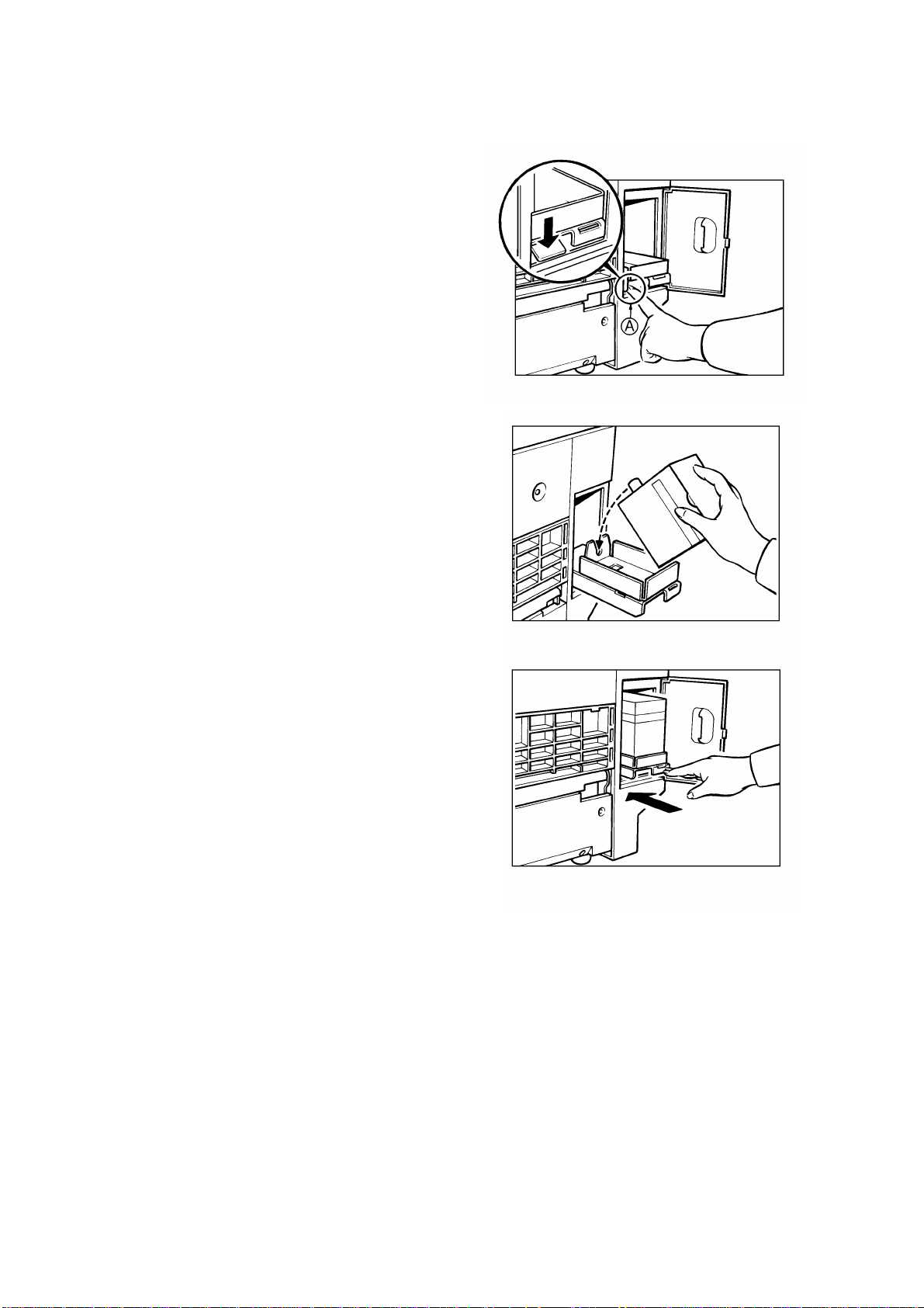
10. Install the ink cartridge as follows:
a. Open the ink cover.
b. Press down the release
lever (green tab [A]).
Then pull out the ink
cartridge holde r .
c. Open the ink cap and set the
ink cartridge as shown i n th e
illustration.
d. Slide in the ink cart r i dg e ho l de r.
Then press the set lever (green
tab) until it clicks in position.
e. Close the ink cover.
11. Make test prints as follows:
a. Adjust the original guide to
match the original size.
b. Set the original face down.
c. Input the desired number of
prints with the number keys
and press the Master Making
key.
d. After one sheet of paper is
delivered, press th e Pr in t Start
key to make prints at the lowest
print speed until the print image
density stabilizes. Use a test
chart to check for changes in the
image density.
e. Check the copy image after about
one hundred pri nts.
C217 3-10 SM
Page 99

30 mm
18
mm
Installation
BRAND STICKER AND NAME PLATE INSTRUCTIONS
This procedure is for the OEM version machine only.
1. Peel off the backing film of the brand sticker (accessory).
2. Adhere the brand sticker to the operation panel as shown.
3. Peel off the backing film of the model name plate (accessory).
4. Adhere the model name plate in the recess on the front cover.
SM 3-11 C217
Page 100

3. TAPE MARKER INSTALLATION
3.1 ACCESSORY CHECK
Check the quantity and cond iti o n of the accesso ri es in th e bo x accor d ing to
the following list:
1. Knob Screw..........................................................................................2
2. Screw M4 x 25 .....................................................................................2
3. Hexagon Nut M4 .................................................................................2
4. Lock washer.........................................................................................1
5. Tape ....................................................................................................1
NOTE:
The kit may contain extra parts that are used to install the tape
marker in other model machines.
C217 3-12 SM
 Loading...