

Page 1

Model:
BRG-P1w
Machine Code:
J034
Field Service Manual
8 January, 2013
Page 2

Page 3

Safety Instructions, Conventions
For your safety, please read this manual carefully before you service the machine. Always keep this
manual handy for future reference.
Safety Information
Always obey these safety precautions when using this product.
Switches and Symbols
Where symbols are used on or near switches on machines for Europe and other areas, the meaning of
each symbol conforms with IEC60417.
Responsibilities of the Customer Engineer
Maintenance
Maintenance shall be done only by trained customer engineers who have completed service training for
the machine and all optional devices designed for use with the machine.
Installation
The main machine and options can be installed by either the customer or customer engineer. The
customer or customer engineer must follow the installation instructions described in the operating
instructions.
Reference Material for Maintenance
Maintenance shall be done with the special tools and the procedures prescribed for maintenance of the
machine described in the reference materials (service manuals, technical bulletins, operating
instructions, and safety guidelines for customer engineers).
• Use only consumable supplies and replacement parts designed for use with the machine.
1
Page 4

Before Installation, Maintenance
Shipping and Moving the Machine
• Work carefully when lifting or moving the machine. If the machine is heavy, two or more customer
engineers may be required to move the machine without causing injury (muscle strains, spinal
injuries, etc.) or damage to the machine if it is dropped or tipped over.
• Personnel working around the machine should always wear proper clothing and footwear. Never
wear loose fitting clothing or accessories (neckties, loose sweaters, bracelets, etc.) or casual
footwear (slippers, sandals, etc.) when lifting or moving the machine.
• Always unplug the power cord from the power source before you move the machine. Before you
move the machine, arrange the power cord so it will not fall under the machine.
Power
• Always turn the machine off and disconnect the power plug before doing any maintenance
procedure.
• After turning the machine off, power is still supplied to the main machine and other devices. To
prevent electrical shock, switch the machine off, wait for a few seconds, then unplug the machine
from the power source.
• Before you do any checks or adjustments after turning the machine off, work carefully to avoid
injury.
• After removing covers or opening the machine to do checks or adjustments, avoid touching
electrical components or moving parts (gears, timing belts, etc.).
After turning the machine on with any cover removed, keep your hands away from electrical
•
components and moving parts.
• Never touch the cover of the fusing unit, gears, timing belts, etc.
Installation, Disassembly, and Adjustments
• After installation, maintenance, or adjustment, always check the operation of the machine to make
sure that it is operating normally. This ensures that all shipping materials, protective materials, wires
and tags, metal brackets, etc., (attached to protect the machine during shipping), have been
removed and that no tools remain inside the machine.
2
Page 5

• Never use your fingers to check moving parts that are causing spurious noise. Never use your
fingers to lubricate moving parts while the machine is operating.
Special Tools
• Use only standard tools approved for machine maintenance.
• For special adjustments, use only the special tools and lubricants described in the service manual.
Using tools incorrectly, or using tools that could damage parts, could damage the machine or
cause injuries.
During Maintenance
General
• Before you begin a maintenance procedure always switch the machine off.
• Disconnect the power plug from the power source.
• Allow the machine to cool for at least 10 minutes.
• Avoid touching the components inside the machine that are labeled as hot surfaces.
Safety Devices
• Never remove any safety device (a fuse, thermistor, etc.) unless it requires replacement. Always
replace a safety device immediately.
• Never do any procedure that defeats the function of any safety device. Modification or removal of
a safety device (fuse, thermistor, etc.) could cause a fire and personal injury. After removal and
replacement of any safety device, always test the operation of the machine to ensure that it is
operating normally and safely.
• For replacement parts use only the correct fuses, thermistors, circuit breakers, etc. rated for use with
the machine. Using replacement devices not designed for use with the machine could cause a fire
and personal injuries.
3
Page 6

Organic Cleaners
• During cleaning never use any organic cleaners (alcohol, etc.) other than those described in the
service manual.
• Make sure the room is well ventilated before using any organic cleaner. Always use organic
solvents in small amounts to avoid breathing the fumes and becoming nauseous.
• Switch the machine off, unplug it, and allow it to cool before doing preventive maintenance.
• To avoid fire or explosion, never use an organic cleaner near any component that generates heat.
Wash your hands thoroughly after cleaning parts with an organic cleaner to avoid contamination
•
of food, drinks, etc.
Power Plug and Power Cord
• Before servicing the machine (especially when responding to a service call), always make sure that
the power plug has been inserted completely into the power source. A partially inserted plug could
generate heat (due to a power surge caused by high resistance) and cause a fire or other
problems.
• Always check the power plug and make sure that it is free of dust and lint. Clean it if necessary. A
dirty plug can generate heat and cause a fire.
• Inspect the entire length of the power cord for cuts or other damage. Replace the power cord if
necessary. A frayed or otherwise damaged power cord can cause a short circuit which could lead
to a fire or personal injury from electrical shock.
• Check the length of the power cord between the machine and power supply. Make sure the power
cord is not coiled or wrapped around any object such as a table leg. Coiling the power cord can
cause excessive heat to build up and could cause a fire.
Make sure that the area around the power source is free of obstacles so the power cord can be
•
removed quickly in case of an emergency.
• Make sure that the power cord is grounded (earthed) at the power source with the ground wire on
the plug.
• Connect the power cord directly into the power source. Never use an extension cord.
• When you disconnect the power plug from the power source, always pull the plug, not the cable.
4
Page 7

After Installation Servicing
Disposal of Used Items
• Ink is flammable. Never attempt to incinerate empty ink cartridges.
• Always dispose of used items in accordance with the local laws and regulations regarding the
disposal of such items.
• To protect the environment, never dispose of this product or any kind of waste from consumables at
a household waste collection point. Dispose of these items at one of our dealers or at an
authorized collection site.
Points to Confirm with Operators
At the end of installation or a service call, instruct the user about use of the machine. Emphasize the
following points.
• Show operators how to remove jammed paper and troubleshoot other minor problems by
following the procedures described in the operating instructions.
• Point out the parts inside the machine that they should never touch or attempt to remove.
• Confirm that operators know how to store and dispose of consumables such as ink cartridges,
ammonia water, paper, etc.
Make sure that all operators have access to an operating instruction manual for the machine.
•
• Confirm that operators have read and understand all the safety instructions described in the
operating instructions.
• Demonstrate how to turn off the power and disconnect the power plug (by pulling the plug, not the
cord) if any of the following events occur:
1. Something has spilled into the product.
2. Service or repair of the product is necessary.
3. The product cover has been damaged.
• Caution operators about removing paper fasteners around the machine. They should never allow
paper clips, staples, or any other small metallic objects to fall into the product.
5
Page 8

Safety Instructions for Ink Cartridges
Accidental Exposure To Ink
• If ink gets on the skin, wash the affected area immediately with soap and cold running water.
• If ink gets into the eyes, immediately flush the eyes with cold running water. If there are signs of
irritation or other problems, seek medical attention.
• If ink is swallowed, drink a strong solution of cold water and table salt to induce vomiting. Seek
medical attention immediately.
• Ink is difficult to remove from fabric. Work carefully to avoid staining clothing when performing
routine maintenance or replacing cartridges.
Handling and Storing Ink Cartridges
• Ink is flammable. Never store ink cartridges in a location where they will be exposed to high
temperature or an open flame.
• Always store ink cartridges out of the reach of children.
• Always store ink cartridges in a cool, dry location that is not exposed to direct sunlight.
Ink Cartridge Disposal
• Attach the caps to empty ink containers for temporary storage to avoid accidental spillage.
• Return empty ink cartridges to a local dealer who can accept such items for collection and
recycling or disposal.
• If the customer decides to dispose of empty ink cartridges, make sure that they are disposed of in
accordance with local laws and regulations.
Safety Instructions for Batteries
• Always replace a lithium battery on a PCB with the same type of battery prescribed for use on that
board.
6
Page 9
• Replacing a lithium battery with any type other than the one prescribed for use on the board could
lead to an explosion or damage to the PCB.
• Never discard used batteries by mixing them with other trash.
• Remove used batteries from the work site and dispose of them in accordance with local laws and
regulations regarding the disposal of such items.
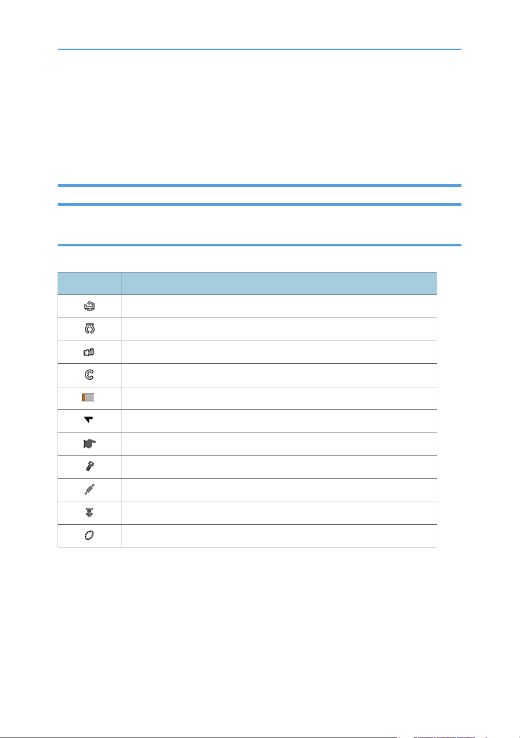
Conventions Used in this Manual
Symbols and Abbreviations
This manual uses several symbols.
Symbol What It Means
Clamp
Clip ring
Connector
E-ring
FFC (Flat Film Connector)
Hook
Pointer (cross-reference to another manual section)
Screw
Spring
Standoff
Timing Belt
This manual uses the following abbreviations.
7
Page 10
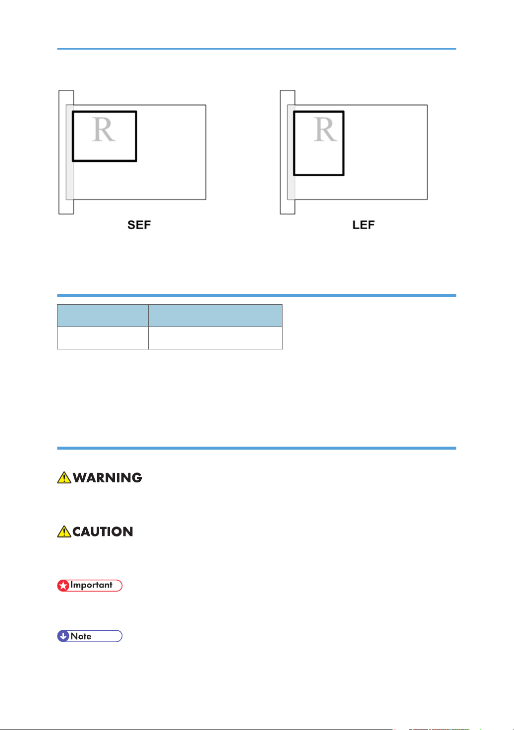
Throughout this service manual, "SEF" denotes "Short Edge Feed" and "LEF" denotes "Long Edge Feed".
Machine Name
Printer Name Model No.
BRG-P1w J034
• The J034 is equipped with the ZICO controller.
• The NIC is mounted on the CTL board.
• The J034 does not support PCL.
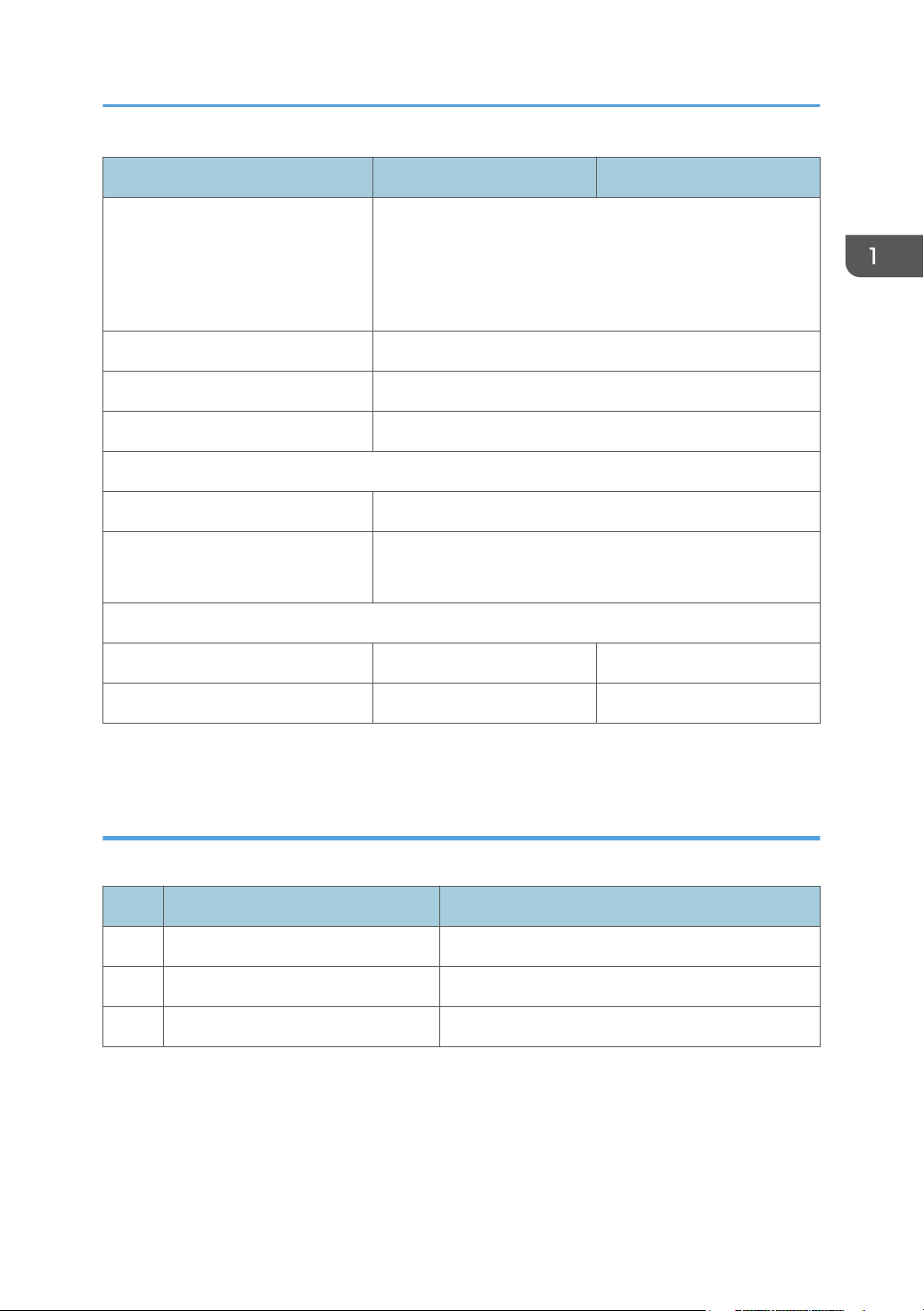
Warnings, Cautions, Notes
In this manual, the following important symbols and notations are used.
• A Warning indicates a potentially hazardous situation. Failure to obey a Warning could result in
death or serious injury.
• A Caution indicates a potentially hazardous situation. Failure to obey a Caution could result in
minor or moderate injury or damage to the machine or other property.
• Obey these guidelines to avoid problems such as mis-feeds, damage to originals, loss of valuable
data and to prevent damage to the machine
• This information provides tips and advice about how to best service the machine.
8
Page 11

Trademarks
• Microsoft®, Windows®, and MS-DOS® are registered trademarks of Microsoft Corporation in the
United States and /or other countries.
• PostScript® is a registered trademark of Adobe Systems, Incorporated.
• PCL® is a registered trademark of Hewlett-Packard Company.
• Ethernet® is a registered trademark of Xerox Corporation.
PowerPC® is a registered trademark of International Business Machines Corporation.
•
• Other product names used herein are for identification purposes only and may be trademarks of
their respective companies. We disclaim any and all rights involved with those marks.
9
Page 12

TABLE OF CONTENTS
Safety Instructions, Conventions........................................................................................................................1
Responsibilities of the Customer Engineer....................................................................................................1
Before Installation, Maintenance..................................................................................................................2
Shipping and Moving the Machine.....................................................................................................2
Power......................................................................................................................................................2
Installation, Disassembly, and Adjustments.........................................................................................2
Special Tools..........................................................................................................................................3
During Maintenance......................................................................................................................................3
General..................................................................................................................................................3
Safety Devices........................................................................................................................................3
Organic Cleaners..................................................................................................................................4
Power Plug and Power Cord................................................................................................................4
After Installation Servicing.............................................................................................................................5
Disposal of Used Items..........................................................................................................................5
Points to Confirm with Operators.........................................................................................................5
Safety Instructions for Ink Cartridges............................................................................................................6
Accidental Exposure To Ink..................................................................................................................6
Handling and Storing Ink Cartridges...................................................................................................6
Ink Cartridge Disposal...........................................................................................................................6
Safety Instructions for Batteries......................................................................................................................6
Conventions Used in this Manual.................................................................................................................7
Symbols and Abbreviations..................................................................................................................7
Machine Name......................................................................................................................................8
Warnings, Cautions, Notes..................................................................................................................8
Trademarks.............................................................................................................................................9
1. Product Information
Specifications....................................................................................................................................................17
Overview..........................................................................................................................................................18
Before You Begin.........................................................................................................................................18
What This Manual Contains...............................................................................................................18
Printer Models and Options...............................................................................................................19
Print Cartridges....................................................................................................................................20
10
Ink Collector Unit.................................................................................................................................20
Page 13

Main Machine.............................................................................................................................................21
Front View............................................................................................................................................21
Left View...............................................................................................................................................22
Rear View.............................................................................................................................................22
Options.........................................................................................................................................................23
External Options: J034.......................................................................................................................23
Guidance for Differences between J034 and that of the base machine
Ink Tube Stay................................................................................................................................................24
Paper Transport Belt Unit.............................................................................................................................24
Rollers...........................................................................................................................................................24
The Paper Feed Roller.........................................................................................................................25
The Connecting Roller.........................................................................................................................25
.....................................................24
2. Installation
Preparation.......................................................................................................................................................27
Environment..................................................................................................................................................27
Choosing a Location....................................................................................................................................27
Minimum Space Requirements...................................................................................................................29
Power Source...............................................................................................................................................29
Using the Operation Panel..............................................................................................................................30
Key Summary Table.....................................................................................................................................30
Printer Display Summary.............................................................................................................................32
Operation Panel: Cartridge replacement indicator.........................................................................32
Operation Panel: Waste Ink Full Indicator
........................................................................................33
Display Menu Summary..............................................................................................................................33
User Menu Mode................................................................................................................................34
Access to menus during an error........................................................................................................39
Installation.........................................................................................................................................................41
Important Information......................................................................................................................................42
Checklist Before Moving the Printer...........................................................................................................42
If the Printer Is Not Used Frequently…........................................................................................................42
3. Preventive Maintenance
PM Table...........................................................................................................................................................43
Service Call Procedures..............................................................................................................................43
11
Page 14

4. Replacement and Adjustment
Before Replacing Parts.....................................................................................................................................45
Removal Table.............................................................................................................................................45
Required Tools.............................................................................................................................................47
Common Procedures........................................................................................................................................48
Simple Removals..........................................................................................................................................48
Duplex Unit..........................................................................................................................................
Ink Collector Unit.................................................................................................................................49
Covers...........................................................................................................................................................50
Cover Names......................................................................................................................................50
Order of Removal Cover....................................................................................................................51
Rear Cover, Top Cover.......................................................................................................................51
Right Front Cover.................................................................................................................................53
Right Cover..........................................................................................................................................54
Port Cover............................................................................................................................................56
Left Cover.............................................................................................................................................56
Canopy Cover.....................................................................................................................................57
Front Cover, Operation Panel Board................................................................................................57
Re-assembly.........................................................................................................................................59
Unlocking, Moving the Carriage................................................................................................................64
Maintenance Unit, Right Ink Sump.................................................................................................................66
Maintenance Unit........................................................................................................................................66
Right Ink Sump..............................................................................................................................................69
48
Encoders...........................................................................................................................................................71
Vertical Encoder Wheel..............................................................................................................................71
Horizontal Encoder Strip.............................................................................................................................73
Reinstallation........................................................................................................................................75
Boards...............................................................................................................................................................78
PSU................................................................................................................................................................78
HVPS.............................................................................................................................................................79
Printer Engine CTL Board.............................................................................................................................80
Before Replacement............................................................................................................................80
CTL Board Replacement.....................................................................................................................81
12
Page 15

After Replacement...............................................................................................................................83
Motors...............................................................................................................................................................86
Horizontal Motor.........................................................................................................................................86
Vertical Motor..............................................................................................................................................88
Fan................................................................................................................................................................91
Clutches.............................................................................................................................................................93
Feed Clutch...................................................................................................................................................93
Transport Belt....................................................................................................................................................96
Transport Belt, Charge Roller, Pressure Plate, Pressure Rollers................................................................96
Sensors, Switches
Vertical Encoder Sensor............................................................................................................................101
Ink Level Sensor.........................................................................................................................................102
1st Registration Sensor..............................................................................................................................104
2nd Registration Sensor............................................................................................................................107
Air Purge Detection Switch.......................................................................................................................108
Top Cover Switch......................................................................................................................................110
Right Front Cover Switch...........................................................................................................................111
Temperature/Humidity Sensor.................................................................................................................113
Trailing Edge Sensor.................................................................................................................................114
Paper End Sensor......................................................................................................................................115
Duplex Unit Set/Cover Open Switch......................................................................................................116
Bypass Drawer Connector........................................................................................................................117
Drive Switching Module and Ink Supply Unit.............................................................................................120
Rollers.............................................................................................................................................................123
Paper Feed Roller......................................................................................................................................123
Connecting Rollers....................................................................................................................................126
..........................................................................................................................................101
Carriage Unit.................................................................................................................................................129
Replacing the Carriage Unit.....................................................................................................................129
Accessories........................................................................................................................................129
Preparation........................................................................................................................................129
Re-installation....................................................................................................................................133
After Replacing the Carriage...........................................................................................................136
Print Head Cleaning and Adjustment...........................................................................................................138
13
Page 16

Preparing for Test Printing.........................................................................................................................138
Nozzle Check............................................................................................................................................138
Nozzle Check Pattern......................................................................................................................138
Color Demo Print.......................................................................................................................................139
Print Head Cleaning..................................................................................................................................140
Print Head Flushing....................................................................................................................................141
Adjust Paper Feed.....................................................................................................................................141
Head Position.............................................................................................................................................143
Registration................................................................................................................................................144
Cleaning
Refurbishing....................................................................................................................................................156
.........................................................................................................................................................146
Maintenance Unit Cleaning.....................................................................................................................146
Connecting Rollers Cleaning....................................................................................................................147
Transport Belt Cleaning............................................................................................................................148
Friction Pad Cleaning................................................................................................................................150
Horizontal Encoder Strip Cleaning..........................................................................................................151
Cleaning procedure.........................................................................................................................151
Horizontal Encoder Sensor Cleaning (TBA)...........................................................................................153
Vertical Encoder Wheel Cleaning...........................................................................................................154
Swap and Repair Flow.............................................................................................................................156
Before Shipping from Customer Site to Repair Center..................................................................157
What You Need...............................................................................................................................157
Refurbishing Flow......................................................................................................................................158
Purging.......................................................................................................................................................158
Clean the Machine....................................................................................................................................160
5. System Maintenance Reference
Service Program Mode.................................................................................................................................161
SP Mode Service Tables...............................................................................................................................162
SP Table Key..............................................................................................................................................162
SP3-XXX......................................................................................................................................................163
Reset and Restoration Settings.........................................................................................................163
Maintenance, Replacement
SP5-XXX......................................................................................................................................................164
14
.............................................................................................................164
Page 17

Input Check: Sensors........................................................................................................................164
Input Check: Sensors........................................................................................................................165
Input Check: Temperature and Humidity........................................................................................165
Input Check: Air................................................................................................................................166
Input Check: Ink Cartridge Set Sensors..........................................................................................166
Input Check: Ink Cartridge Levels....................................................................................................167
Print an Engine Maintenance Summary..........................................................................................167
SP7-XXX......................................................................................................................................................167
Display Count: Machine Total.........................................................................................................167
Display Count: User Cleaning.........................................................................................................168
Display Count: User Flushing
Date Display SC Log........................................................................................................................168
Display Total Count: SC Log............................................................................................................169
Display Jam Log................................................................................................................................169
Display Total Count: Jam Log..........................................................................................................169
Status Reports.................................................................................................................................................171
1. Page Counter........................................................................................................................................173
2. Config. List.............................................................................................................................................174
3. Service Summary..................................................................................................................................175
4. Engine Summary Chart.........................................................................................................................175
Firmware Updates.........................................................................................................................................179
Operating Environment and Other Requirements..................................................................................179
Update Cautions.......................................................................................................................................179
Firmware Update Operating Instructions................................................................................................180
Bidirectional-Enabled................................................................................................................................181
Bidirectional-Disabled...............................................................................................................................183
...........................................................................................................168
6. Troubleshooting
Troubleshooting Guide..................................................................................................................................187
Image Problems.............................................................................................................................................188
Basic Check Points and Specifications....................................................................................................188
Problems and Solutions....................................................................................................................190
Error Codes....................................................................................................................................................198
Operation Panel Display..........................................................................................................................198
15
Page 18

Operation Panel Messages......................................................................................................................200
Service Call Conditions.............................................................................................................................206
SC code display patterns and how to clear them..........................................................................206
Service Call Code Tables.........................................................................................................................207
Jam Codes
Status Monitor Messages.........................................................................................................................234
.................................................................................................................................................224
Jam Codes.........................................................................................................................................224
Jammed paper location...................................................................................................................233
7. Energy Saving
Energy Save...................................................................................................................................................239
Energy Saver Modes................................................................................................................................239
Timer Settings....................................................................................................................................239
Return to Standby Mode..................................................................................................................239
Recommendation..............................................................................................................................240
Paper Save.....................................................................................................................................................241
Effectiveness of Duplex/Combine Function............................................................................................241
1. Duplex:..........................................................................................................................................241
2. Combine mode:............................................................................................................................241
3. Duplex + Combine:......................................................................................................................241
Recommendation..............................................................................................................................242
Duplex Mode Tables........................................................................................................................242
16
Page 19

1. Product Information
Specifications
See "Appendices" for the following information:
• Printer Engine
• Supported Paper Sizes
• Control Boards
17
Page 20

1. Product Information
Overview
Before You Begin...
What This Manual Contains
This Service Manual covers J034 model of this printer series. This is a brief summary of the differences
between J034 and that of base machine J028.
J028
The NIC is mounted on the CTL board.
This model is PCL compatible.
J034
The NIC is mounted on the CTL board.
This model is not PCL compatible.
This table below compares the J034 model with that of base machine J028. The size and number of
components differ in some cases but their basic design and function are almost the same. The removal
procedures described in the manual apply to this model.
J028 J034
Main Components
Print Heads x2
Maint. Unit Common
Ink Supply Unit Common
Ink Collector Unit Common
Ink Cartridges S size, M size
Horizontal Encoder Film Common
Duplex Std Std
Wireless LAN No No
PCBs
18
CTL Board*
1
FIGO ZICO
Page 21
J028 J034
PSU Common
This depends on the territory in which it will be used.
Europe and Asia: 200V board
North America: 100V board
Supply Unit Board Common
Carriage Unit Board Common
Operation Panel Black
Covers
Right Front Door Product Name Printed on Each
Other Covers The right, left, and duplex unit covers are black.
All other covers are white.
Overview
Options
Multi Bypass Yes (J313) Yes (J315)
PFU Yes (J312) Yes (J314)
*1 The NIC is mounted on the CTL board of the J028/J034.
Printer Models and Options
This manual describes the following printer model and options.
No. Name Ricoh Name
J034 BRG-P1w Aficio SG 7100DN(SG 7100DN)
J314 Paper Feed Unit Paper Feed Unit TK1190
J315 Multi Bypass Tray Multi Bypass Tray BY1050
The electrical components and mechanisms that drive this printer and that of base machine are nearly
identical. However, you should note these differences about options:
• The Paper Feed Unit TK1190 (J314) is an optional paper tray that holds 250 sheets. Only one
paper feed unit can be attached (comprising two drawers together with the standard Tray 1).
19
Page 22
1. Product Information
Print Cartridges
The following print cartridges can be used with the J034.
Name Comments
Starter Ink Cartridge (K)*
Starter Ink Cartridge (C) *
Starter Ink Cartridge (M) *
Starter Ink Cartridge (Y) *
1
1
1
1
These are the starter cartridges shipped with the
machine. These are used to initialize ink supply when
the machine is installed and then discarded.
Print Cartridge GC 41K
Print Cartridge GC 41C
These are medium-size cartridges.
Print Cartridge GC 41M
Print Cartridge GC 41Y
Print Cartridge GC 41KL*2
Print Cartridge GC 41CL*2
These are small-size cartridges.
Print Cartridge GC 41ML*2
Print Cartridge GC 41YL*2
*1: Always use the starter cartridges shipped with the machine to initialize ink supply at installation.
Never install used ink cartridges to initialize ink supply at installation.
*2: L = Low
• The large-size cartridges are supplied only for the Japan domestic models.
Ink Collector Unit
The ink collector unit is installed on the right side of the machine behind the right front door below the ink
supply unit.
Collector Comment
Ink Collector Unit IC 41 Ink Collector Unit for all models.
20
Page 23

Main Machine
Front View
1. Top cover
Open to see inside the printer if a jam occurs.
Overview
2. Operation panel
Operation keys and the 2-line LCD. The operation panel can be raised and set in the upright
position if the printer is placed at a height where it is difficult to reach.
3. Ink cartridges (K), (C), (M), (Y)
Supply ink to the print heads.
4. Ink collector unit
Pull out the ink collector unit when it needs to be replaced, or before servicing the printer.
5. Right front cover
Covers the ink cartridges and the ink collector. Open only when installing or replacing Ink
cartridges, or when pulling out the ink collector unit. Otherwise, this door should remain closed. A
small switch detects when this cover is open and closed. The door must be closed for the printer to
operate.
6. Paper cassette (Standard Tray 1)
This is the standard tray that holds paper fed to the machine.
7. Paper output tray and extension
Holds paper that has exited the printer. Pull out the output tray extension when printing on paper
longer than A4 or LTR.
21
Page 24
1. Product Information
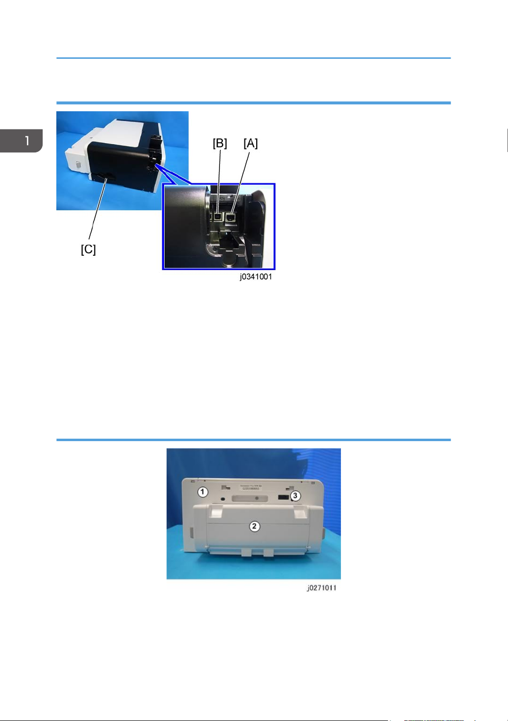
Left View
A: Ethernet port
The port for the ethernet cable. The NIC is mounted on the controller board.
B: USB port
This is the connection point for the USB cable from the PC.
C: Power inlet
The connection point for the power cord. Use only the detachable power cord provided with the printer.
Make sure you ground (earth) the head of the plug at the power source.
Rear View
1. Rear cover
2. Duplex unit
22
The duplex is standard for the J034 (it is not an option). It is easily detached and re-attached. A
small switch detects the presence or absence of the duplex unit.
Page 25

3. Bypass tray connection point
This is the connection point for an optional multi bypass tray.
Options
External Options: J034
Overview
The Paper Feed Unit TK1190 (J314) [A] is used with the J034 only. Only one paper feed units can be
installed.
The Multi Bypass Tray BY1050 (J315) [B] can be used with the J034 only.
23
Page 26
1. Product Information
Guidance for Differences between J034 and that of the base machine
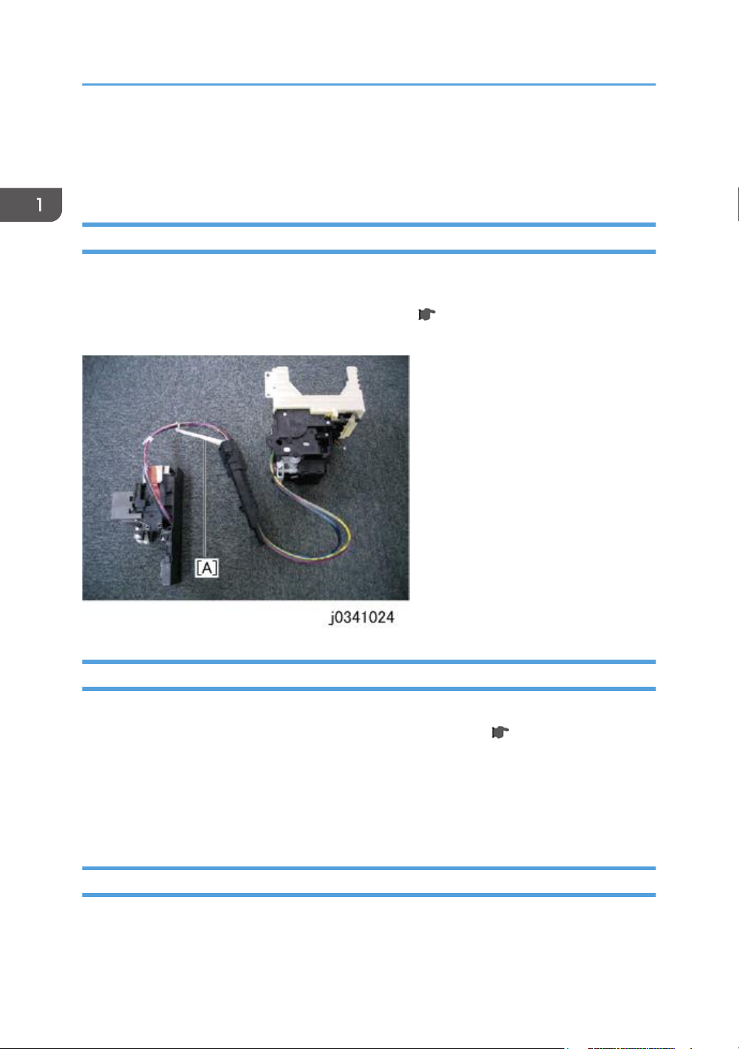
Ink Tube Stay
The J034 model adds the ink tube support stay [A] between the carriage and the ink supply unit so that
the large size papers can be printed smoothly. However, this stay requires no additional steps for the
replacement. Pay extra attention to remove the carriage unit ( p.129) from the main machine to
avoid damaging to this stay.
Paper Transport Belt Unit
For supporting the large size papers, The J034 machine’s width is increased consequently. This changes
some replacement procedures. Regarding as the paper transport belt unit ( p.96 "Transport Belt"),
the following procedures are changed.
• The carriage unit should be removed before removing the belt unit.
• The number of the pressure plate’s screws becomes 4.
• The number of the pressure plate’s springs becomes 6.
Rollers
The Pickup roller and the connecting roller removing procedures are also changed in some parts.
24
Page 27

Guidance for Differences between J034 and that of the base machine
The Paper Feed Roller
• The two e-rings should be released to remove the pressure rollers that pinch the paper feed roller
( p.123).
The Connecting Roller
• The ink level sensor should be removed to pull out the right side of the connecting roller shaft ( p.
126 "Connecting Rollers") from the main machine.
25
Page 28

1. Product Information
26
Page 29
2. Installation
Preparation
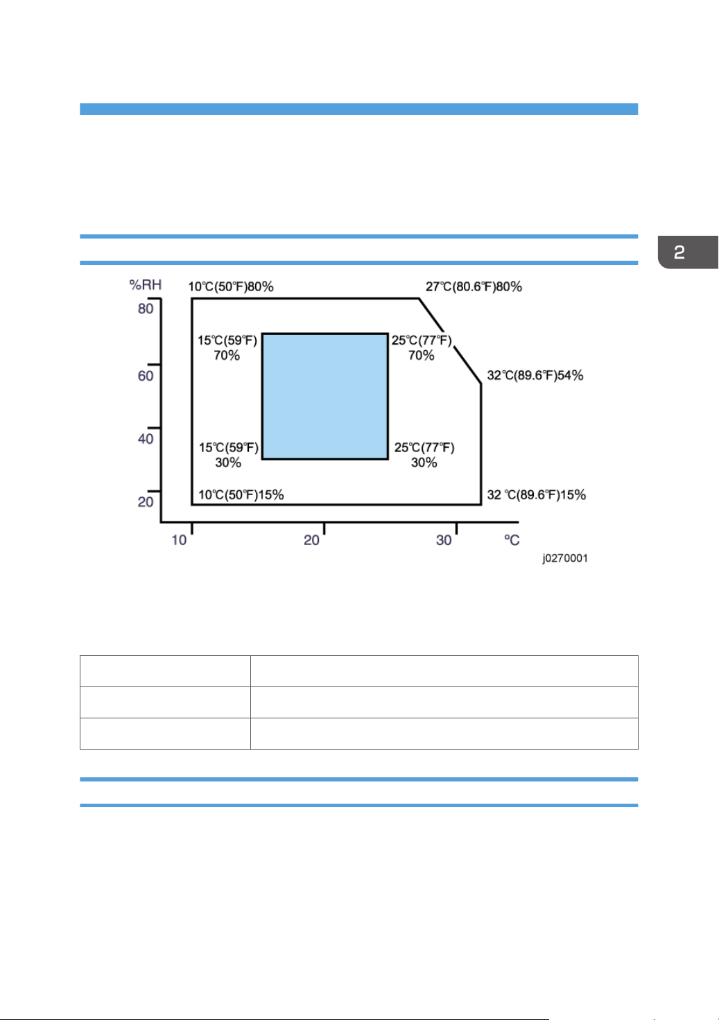
Environment
• White area: Permissible Range
• Blue area: Recommended Range
Set up the machine in a location that meets these minimum requirements:
Temperature Range: 10°
Humidity Range: 15% to 80% RH
Ambient Illumination: Less than 2,000 Lux (never expose to direct sunlight).
C to 32°C (50°F to 89.6°F)
Choosing a Location
1. Always install the machine:
• On a sturdy, level surface.
• Where it will not become damp.
2. Make sure the machine is never exposed to:
27
Page 30

2. Installation
• Extreme changes from low to high temperature or high to low temperature.
• Cold or cool air directly from an air conditioner.
• Heat from a space heater.
3. Never install the machine in areas near:
Dust, lint, or corrosive fumes.
•
• Strong vibration.
4. Do not use the machine at any location higher than 2,500 m (8,200 ft) above sea level.
5. Set up and use the machine on a sturdy, level surface.
• Place a carpenter's level on the machine front-to-back, and side-to-side and confirm that it is
level.
• Variations between the front/back and left/right level readings should be less than 2
degrees.
Required Software Environment
Software • Microsoft Windows XP/Vista/Windows 7
• Microsoft Windows Server 2003/2003 R2/2008/2008 R2
• Mac OS X 10.5 Leopard and later versions*1
• PC/AT-compatible computer with USB or network interface
• Macintoshes that are PowerPC G3 or higher with USB port or network port
Hardware
• Macintoshes that are Intel Core Duo or higher with USB port or network port
• 80-100 MB of HDD space available
*1: Mac driver included on CD-ROM (The supported languages are English, French, German and
Japanese.).
28
Page 31

Minimum Space Requirements
a. At least 26 cm (10.3 inches)
Preparation
b. At least 3 cm (1.2 inches)
c. At least 45 cm (17.8 inches)
d. At least 10 cm (4.0 inches)
e*1. At least 13 cm (5.2 inches)
*1 A clearance of 30 cm (11.9 inches) is necessary if the multi bypass tray is attached.
Power Source
J034
North America 100-120 V: 50/60 Hz 1.2 A (when fully equipped)
Europe 220-240 V: 50/60 Hz 0.6 A (when fully equipped)
29
Page 32

2. Installation
Using the Operation Panel
Here is a brief description of how to use the keys on the printer operation panel. This information is
provided as a quick summary of important information described in the Operating Instructions.
Key Summary Table
Key/Indicator What It Does
1 Power Press this key to turn the power on. To turn the power off, press and hold
2 Job Reset When the machine is online, press this key to cancel an ongoing print job.
3 Form Feed When the printer is offline, push to print all the data in the printer buffer.
4 Escape Push to restore the display to the previous condition.
30
down this key for one second.
Blinks when the printer is receiving data from a computer or if there is data
to be printed.
If there is a paper jam, press this key according to the displayed error
message and remove the jammed paper.
Page 33

Key/Indicator What It Does
Using the Operation Panel
5
/Menu
[ ], [ /Menu]: Increase or decrease values on the display when making
settings.
[ /Menu]: When the printer is in standby mode, press [ /Menu] key to
enter the user menu.
6 Cartridge
Show the ink levels of the print cartridges.
replacement
indicator
7 Waste ink full
Show the waste ink levels of the ink collector unit.
indicator
8 Display Shows the current printer status and error messages.
9 Alert indicator The symbol appears in the LCD when an error occurs.
Red indicator illuminating: Indicates an error that requires the
•
operator or service representative to deal with. Printing stops.
• Red indicator flashing: An alert message appears. Follow the
instruction that appears in the display.
10 #Enter Push to execute the menu item on the display.
11
No-Fuss Head
Cleaning
When the machine is in standby mode, press the [Job Reset] and [Form
Feed] keys at the same time to perform head cleaning for all colors.
31
Page 34

2. Installation
Printer Display Summary
Operation Panel: Cartridge replacement indicator
The printer shows a multi-level dynamic display that keeps the operator informed about the status of the
ink levels in the tanks. The example below for Black (K) shows the progression in the display from full on
the left to completely empty on the right.
A software count determines when the ink cartridge is has less than 20% ink remaining. The 0% and Ink
Out display begin flashing alternately at 3 sec. intervals. This is the near-end alert.
When the cartridge is empty the machine issues the ink-end alert and printing stops.
32
Page 35

Using the Operation Panel
The operator can continue printing by pressing [Form Feed] on the operation panel. The printer will
continue to print until the print head ink tank is empty. However, in this operation mode the machine
cannot perform print head maintenance.
Operation Panel: Waste Ink Full Indicator
The amount of waste ink in the ink collector unit is indicated on a six-step scale, namely 0, 20, 40, 60,
80, and 100%. It is reset to 0% if a new ink collector unit is installed. If it reaches 100%, printing cannot
be done. A message prompting the user to replace the unit appears on the panel display. A message
prompting the user to replace the ink collector unit appears also if it is not mounted.
The amount of waste ink can be displayed also on the Status Monitor and Web Image Monitor.
On the other hand, "Ink C.U. Space" in the machine's menu on the control panel displays the available
storage space left in the ink collector unit. (It is reset to 100% if a new ink collector unit is installed.)
Display Menu Summary
Here is a summary of the function menus. Items needed for printer maintenance or troubleshooting are
marked in the left column with an asterisk (*).
33
Page 36

2. Installation
User Menu Mode
Menu/Menu Item Function
Counter Displays or prints the number of pages printed in B&W, full color, and
Economy Color.
Note: Changing Bit SW 5 modifies the display:
• Setting Bit SW 5-6 to "0" switches the Economy Color display off.
• The default setting for Bit SW 5-6 is "1". Mono and Economy Color are
both displayed.
Show Counter Displays the counters on the LCD ("Black", "Color")
Prints the "Page Counter" report that lists: the machine serial number, Total
Print
Full Color, Total Mono Color, Total Economy Color, and Total Duplex. It
also lists Coverage information for full color, mono, and Economy Color.
Paper Input
Paper Type Specifies type of paper loaded in the paper tray.
Tray Paper Size Specifies size of paper to be loaded in the paper tray.
Note: The setting of Bit SW6-7 determines whether hidden functions (hidden
paper sizes A5 SEF, B6 SEF) are displayed:
• 0: No A5 SEF, B6 SEF display (default)
• 1: A5 SEF, B6 SEF displayed
Aut. Tray Select Specify that the paper tray be automatically selected. The paper tray will
automatically be selected according to the paper size and paper type. Tray
1 (the standard paper cassette) is the default. "Tray 2" and "Tray 3" appear
only if the paper feed unit(s) is attached. "Bypass Tray" appears only if the
bypass tray is attached.
Tray Priority
You can specify the prioritized paper tray. This setting appears only if the
paper feed unit or multi bypass tray is attached.
List/Test Print
34
Page 37

Using the Operation Panel
Menu/Menu Item Function
Config.Page(*) Prints information that tells you the current configuration of the printer.
• System Reference. Lists printer version, attached options, name of print
language, amount of ink remaining for each ink cartridge.
• Paper Input. Lists the specified Tray Priority setting and the Paper Input
menu settings.
• Host Interface, Interface Information. Lists the settings of the Host
Interface menu
Color Demo Page Prints a color sample.
Error Log Prints list of most recent errors.
PCL Config. Page Lists current PCL configuration
Maintenance
Nozzle Check(*) Prints the cross-hatch test pattern so you can visually confirm whether inks are
ejecting correctly from the print head.
Head-cleaning(*) Cleans the print head. Clean the print head when certain colors are missing
or printing faintly. Head cleaning consumes ink.
Head-flushing(*) Cleans the print head more thoroughly than "Head-cleaning". Flushing
consumes more ink. Use this function only after "Head-cleaning" fails to solve
the problem.
Head Position(*) Adjusts the alignment of the print head if the Nozzle Check test pattern
shows broken vertical lines, or if printed images are blurred.
Adj. Paper Feed(*) Adjusts the paper feed setting if the Nozzle Check test pattern shows
horizontal misalignment, or if printed images appear uneven.
Registration Adjusts the print starting point for each paper tray. Use the Nozzle Check
test pattern as reference.
Date/Time Allows setting current date/time.
Key Repeat Enables/disables repetition of a key pushed and held down on the
operation panel.
35
Page 38

2. Installation
Menu/Menu Item Function
Dry-delay (Exit) To prevent spoiling of printed copies, select a print delivery interval to allow
them to dry.
The interval must be long enough to allow a sheet to dry. You can specify an
interval between 1 and 20 seconds.
Default: [Off]
Dry-delay (Dup) Pauses printing to allow first side of duplex print to dry before printing
second side of same page.
Note: Supported by the J028/J029 only.
Paper Feed Test(*) Feeds and ejects 1 blank sheet of paper to remove moisture inside the
machine.
De-condensation(*) Feeds and ejects 3 blank sheets of paper to remove moisture inside the
machine.
System
Prt. Err Report Prints error report.
Auto Continue Determines how the printer handles a print job when the specified paper size
and type is not loaded in the tray.
Off: The job does not print if the specified paper size/type is not loaded in
the tray. The job will execute once the specified paper size/type is loaded.
On: The job prints even if the specified paper size/type is not loaded in the
tray.
Sub Paper Size Determines whether to print on A4 paper if LT size paper is specified in the
printer driver, and vice versa.
Default: Off
Energy Saver Switches the energy saving function on/off. When this function is on, the
printer will automatically shut down some of its functions automatically after it
remains idle for the prescribed amount of time.
The "E. Saver Timer" can be set for 5, 15, 30, 35, 60 min.
Once the printer enters the energy save mode, it will require some time to
recover full operation once it receives a print job.
Notify by Email Determines whether a notification is sent to a specified email address when a
printer error occurs. Be sure to cycle the printer off/on after doing this
setting.
36
Page 39

Menu/Menu Item Function
Memory Usage Frame Priority, Font Priority
Unit of Measure Determines the units of measure ("mm" or "in.")
Default: mm
Page Size Allows selection of page size.
Paper Type Plain Paper, IJ Plain Paper, Glossy Paper, Thick Paper, Postcard, Inkjet
Postcard, Envelope
Preprinted Ppr. Off, On
Copies Allows selection of number of copies: 1 to 999.
Blank Pg. Print On (Prints), Off (Does Not Print)
Tray Switching Off (Does Not Switch Trays), On (Switches Trays)
Uni-direct Prt. Env. Selector: On, Auto Detect, Always
Using the Operation Panel
Density Dark, Light, Standard
Color Mode Color, Economy Color, Black and White
Recycl. Ppr. Mode Off, On
Pg Recov. Error Specify whether or not [Page Recovery Error] is reported.
Default: [Display]
Ink C.U. Space Displays the current status of ink collector unit. The number means the
amount of space remaining. (100% means the unit is empty.)
Ppr. Size Error This function enables the printer to notify users if the paper in the tray does
not match the paper size specified in the [Paper Input] menu.
Default: [Display]
Host Interface
I/O Timeout Determines how long the printer waits for the interface to respond. After the
specified time elapses, the printer can receive data from another interface. If
the specified time is too short, a timeout might occur while a data transfer is
in progress. If this occurs, the print job will be interrupted by a new job from
another interface. Default: 15 sec.
37
Page 40

2. Installation
Menu/Menu Item Function
Network Setup Use to do the network settings.
Setting Default
Machine Name Display only
Host Name Display only
Domain Name Display only
IPv4 DNS ServerAddress 1 and 2
0.0.0.0
IPv4 DDNS On
DHCP Off
IPv4 Address 11.22.33.44
Pv4 Subnet M 0.0.0.0
Network Setup Pv4 Gatewy. Ad 0.0.0.0
IPv6 DDNS On
IPv6 DNS ServerAddress 1 and 2
::
DHCPv6 Off
IPv6 Statlss Ad On
IPv6 Address Manual Confg Ad
MnCfgAd PrfxLen
IPv6 Gatewy.Ad. 0:0:0:0:0:0:0:0
Active Protocol IPv4: Active
IPv6: Active
HTTP (IPv4): Active
HTTP (IPv6): Active
Web: Active
38
Page 41

Menu/Menu Item Function
Network Setup IPsec Off
MAC Address Display only
Ethernet Speed Auto Select
Prmt SNMPv3 Com Cleartext
Pmt SSL/TLS Com IPv4: Active
IPv6: Active
Restore Default ---
USB Setting Two settings are available:
USB Speed.
•
• Auto: 480 Mbps or 12 Mbps automatically adjusted
• Full Speed: 12 Mbps fixed
Using the Operation Panel
Default: Auto. Normally, this setting does not require changing.
•
Port Setting.
• Specifies communication settings for a USB connection.
• Default: Off
Language You can select which language the menu is displayed in.
The "Language" menu will be displayed in English.
• NA model
Japanese, English, French, German, Italian, Spanish, Dutch,
Norwegian, Danish, Swedish, Portuguese, Finnish (Default: English)
• EU/Asia model
Same as above plus: Czech, Polish, Hungarian
Access to menus during an error
In previous models, menus could not be accessed during an error. However, this model allows access to
user menus by pressing the [ /Menu] key.
However, functions that require printing, such as the printing of the counter, cannot be executed during
an error.
example:
• Counter. The counts can be displayed but not printed.
39
Page 42

2. Installation
• List/Test Print. No selections are available.
Even without computers, you can specify settings, such as the time and date, on the machine's control
panel.
• Menus could not be accessed while the printer is busy.
40
Page 43

Installation
Installation
These machines and all peripherals are installed by the customer.
The installation procedures are described in the operating instruction manuals issued to the customer
with purchase of the main machine or peripheral unit.
41
Page 44

2. Installation
Important Information
Make sure that the customers understand the following points about moving, storing, and using the
printer.
Checklist Before Moving the Printer
1. Turn the printer off. Disconnect the power cord.
• Never disconnect the power cord without first turning off the printer.
2. To lift the printer, grip it at the center of each side by the hand recesses provided.
3. Never grip the duplex unit on the back of the printer.
4. Make sure the covers and trays are closed. Secure them with tape. Attach the tape at the same
area you removed at the time of installation.
Disconnect the power cord. Tape the power cord to the back of the printer.
5.
6. Remove all paper in the feed trays.
7. Do a test print to confirm that the printer operates correctly after you move it to another location. Do
the cleaning procedures with the printer driver, if necessary.
8. The ink cartridges should remain in the printer. It is not necessary to remove the before transporting
the printer. However, ink must be purged from the print head tanks before the printer is transported.
(See procedure below.)
• To avoid ink spillage, always hold the printer level when you move it.
• Work carefully to avoid dropping it or colliding with other objects in the work area.
If the Printer Is Not Used Frequently…
1. Turn the power off, disconnect the USB cable, and unplug the power cord.
2. To prevent the print nozzles from drying out, periodically print something.
3. Turn the printer on for a few minutes once a month.
4. After storage or a long period of disuse, use the printer driver to print a nozzle check text pattern
and clean the print head nozzles if necessary.
42
Page 45

3. Preventive Maintenance
PM Table
There are no PM Parts in this machine.
Service Call Procedures
The procedures listed below should be done by the service technician. For more details about how to do
these procedures, please refer to "Cleaning Procedures".
Description At Service Call, or As Required
External Covers Damp cloth.
Connecting Rollers,
Paper Feed Roller
Friction Pad Damp cloth. This is the cork friction pad on the front edge of the standard
Maintenance Unit Damp cloth. Always use a tightly wrapped damp cloth to remove the ink
Printer Operation, Print
Quality
Transport Belt Slightly damp cloth. Then dry cloth.
Horizontal Encoder
Strip
Vertical Encoder Wheel Clean linen cloth, dampened with alcohol. Do not use cotton, tissue paper,
Damp cloth. Rotate the roller freely as you clean it.
paper cassette.
that has hardened around the suction cap and wiper blade when you
replace the ink collector unit.
Print a Nozzle Check Pattern and check the results. Clean the print heads if
necessary. For more, see "Print Head Cleaning and Adjustment" in section
"4. Replacement and Adjustment".
Important: To protect the surface of the transport belt, never use alcohol or
any other type of organic solvent.
Clean linen cloth, dampened with alcohol. Do not use cotton, tissue paper,
any material that could shred and leave fibers.
any material that could shred and leave fibers.
43
Page 46

3. Preventive Maintenance
44
Page 47

4. Replacement and Adjustment
Before Replacing Parts
Removal Table
The swap-and-repair system is used for this printer. The table below lists the level of difficulty for
replacement of each item.
Level 1: No Tools Required
Component Comments
1 Duplex Unit Standard. Back of machine
2 End Fence Inside paper cassette
3 Ink Cartridge Front
4 Ink Collector Unit Front
5 Paper Cassette Standard
6 Paper Output Tray On top of paper cassette
7 Right Front Cover Front
8 Port Cover Left side
Level 2: Replaced by Service Technician
Component Difficulty: Low, Medium, High
1 Canopy Cover Low
2 Top Cover Low
3 Rear Cover Low
4 Right Cover Low
5 Left Cover Low
6 Front Cover Low
7 Connecting Rollers Low
45
Page 48

4. Replacement and Adjustment
Component Difficulty: Low, Medium, High
8 Front Cover Low
9 High Voltage Power Supply (HVPS) Low
10 Maintenance Unit Low
11 OPU (Operation Panel Unit) Low
12 PSU Low
13 Vertical Encoder Sensor Low
14 Vertical Encoder Wheel Low
15 Vertical Motor Low
16 Controller Board Medium
17 Cooling Fan Medium
18 Right Ink Sump Medium
19 2nd Registration Sensor High
20 Carriage Unit High
21 Friction Pad High
22 Horizontal Motor High
23 Transport Belt High
24 Air Purge Detection Switch Low
25 Drive Switching Position Sensor High
26 Maintenance Unit Control Sensor High
27 Drive Switching Motor High
28 Drive Motor (DC Motor) High
29 Temperature/Humidity Sensor High
30 Paper End Sensor High
46
31 Paper Feed Roller High
32 Charge Roller Medium
Page 49

Before Replacing Parts
Level 3: Require precision adjustment at factory (Not Replaced in this Field)
Component Comments
--- None ---
Required Tools
This is a list of tools needed to service the machines. These tools are used to keep the print heads from
drying out during long periods of storage following machine repair. (The ink is purged and fresh
cleaning liquid is supplied.)
Item Description Qty Unique or Common
1 Ink Cartridge K Cleaning Assy 1 U
2 Ink Cartridge C Cleaning Assy 1 U
3 Ink Cartridge M Cleaning Assy 1 U
4 Ink Cartridge Y Cleaning Assy 1 U
5 Special Cloth 10 pcs/bag 1 C (PG-C1)
• Parts 1 to 4 are used at the Repair Center.
47
Page 50

4. Replacement and Adjustment
Common Procedures
Simple Removals
Duplex Unit
48
1. Push and hold the left and right release tabs [A] together to unlock the duplex unit [B].
2. Pull the duplex unit out of the machine.
Reinstallation
• The duplex unit must be installed in the machine at all times. The machine will not operate without
the duplex unit installed.
• The locks on either end of the duplex unit lock automatically when the unit is attached to the back
of the printer.
Page 51

Common Procedures
Ink Collector Unit
Before you begin:
Never remove the ink collector unit unless it requires replacement. A message will appear and tell you
that the ink collector unit needs to be replaced.
• You will need a self-sealing plastic bag to hold the ink collector unit.
• When you dispose of the used ink collector unit always obey the local laws and regulations
regarding the disposal of such items.
At any time you can determine if the ink collector unit needs to be replaced.
• Never attempt to clean and re-use an ink collector unit.
To remove the ink collector unit:
1. Gently touch the right front cover to release and open it.
2. Pull the ink collector unit [A] out.
3. The ink collector [A] is completely enclosed to prevent leakage.
4.
If you are replacing the ink collector unit, insert the new one.
49
Page 52

4. Replacement and Adjustment
5. Push in the ink collector [B] until you hear it snap and lock in place.
6. Close the right front cover.
• The ink collector unit has an internal ID chip that automatically resets the counter for the ink
collector unit. No SP adjustment is required.
7. Discard the used ink collector unit.
• Obey the local laws and regulations regarding disposal of items like the full ink collector unit.
• Never attempt to open and clean a full ink collector unit and use it again.
Covers
Cover Names
50
[A] Top Cover
[B] Canopy Cover
[C] Front Cover Brand Logo attached
[D] Operation Panel
[E] Right Front Cover Product Logo attached
[F] Output Tray
Page 53

[G] Paper Cassette
[H] Rear Cover
[I] Duplex Unit
[J] Right Cover
[K] Left Cover
Common Procedures
[L] Port Cover *
1
No screws, tabs only.
*1 This picture is a shot that is taken with the port cover opened because of the easily view.
Order of Removal Cover
It is very important that you understand how to remove and reinstall the covers before doing
replacement procedures. Here is a general summary of the order of removal.
Rear Cover, Top Cover
Preparation
• If you are servicing the J034 with one paper feed unit attached, remove the printer from the top of
the paper feed unit. The rear cover cannot be removed with the printer mounted on a PFU.
• Duplex unit ( p.48)
51
Page 54

4. Replacement and Adjustment
1. Raise the top cover [A].
52
2. 3 screws ( x 3).
Page 55

Common Procedures
3. Press the tabs [A] on the top left and top right of the rear cover to detach the top of the
rear cover.
4. Slide the rear cover up to detach its bottom.
5. Disengage the top cover latch [A].
Right Front Cover
53
Page 56

4. Replacement and Adjustment
1. Open the right front cover [A].
2. Disengage the latch.
3. Remove the right front cover.
Right Cover
Preparation
• Duplex unit ( p.48)
• Right front cover (See above)
54
Page 57

1. Raise the top cover [A].
2. 2 screws ( x 2).
Common Procedures
3. Pressing the tab [A] on the rear cover, lift the right cover [B] to detach it.
55
Page 58

4. Replacement and Adjustment
Port Cover
1. Pressing the tab [A], detach the port cover [B].
When you detach the left cover, detach the port cover in advance.
Left Cover
Preparation
• Duplex unit ( p.48)
• Port cover (See above)
• Rear cover ( p.51 "Rear Cover, Top Cover")
• Top cover( p.51 "Rear Cover, Top Cover")
56
Page 59

1. 2 screws ( x2).
2. Holding the cover's center bottom [A], lift the cover [B] to detach it.
Canopy Cover
Preparation
• Duplex unit ( p.48)
• Rear cover ( p.51 "Rear Cover, Top Cover")
• Top cover ( p.51 "Rear Cover, Top Cover")
• Right cover ( p.54)
• Left cover ( p.56)
Common Procedures
1. Remove the screw ( x1).
2. Remove the canopy cover [A].
Front Cover, Operation Panel Board
Preparation
• Duplex unit ( p.48)
• Rear cover ( p.51 "Rear Cover, Top Cover")
• Top cover ( p.51 "Rear Cover, Top Cover")
• Right cover ( p.54)
• Left cover ( p.56)
• Canopy cover (See above)
57
Page 60

4. Replacement and Adjustment
1. Open the right front cover.
2. Remove the ink cartridges.
58
3. Remove the screws ( x2).
4. The operation panel board [A] is located behind the front cover.
Page 61

Common Procedures
5. Release the clip fastening the flexible flat cable (FFC) and detach the cable from the
board.
6. Slide the front cover [A] to the left to detach it.
7. Release the tabs and detach the operation panel board [A] ( x5, x1).
Re-assembly
Here are some points you should always check before re-attaching the covers.
59
Page 62

4. Replacement and Adjustment
Operation Panel
1. Make sure that the blue band of the FFC edge connector [A] is facing up.
• The blue band must be facing up when you reconnect the FFC to the operation FFC connector.
• If the FFC is twisted and connected with the blue band facing down, the printer will not
operate.
Front Cover
1. Align the tabs (three points) on the left bottom of the front cover with the machine's frame
and slide the cover to attach it.
60
Page 63

Right Cover
1. Check that the harness and ink tube are secured.
• Be sure to secure the harness with the tabs (at five points).
Common Procedures
• Be sure to secure the ink tube with the tabs (at three points).
61
Page 64

4. Replacement and Adjustment
2. Check the maintenance unit [A].
• If the triangles are not aligned as shown above, this means the print head is locked and ready
for operation. You can re-attach the right cover.
62
• If the triangles are aligned tip-to-tip as shown at [A], this means the carrier is unlocked (not
ready for operation) and can be moved manually.
•
Insert a screwdriver at [B], turn it counter-clockwise to rotate the lower triangle around until it
is at [C]. This locks the carrier for normal operation.
Page 65

3. Check the connection with the front cover.
• As shown above, slide the right cover along the guide rail on the front cover to attach it.
Common Procedures
• Align the slit on the right cover with the projected part [A] on the machine's frame to secure the
cover.
Left Cover
1. Check that the harness is secured with the clamps (at three points).
63
Page 66

4. Replacement and Adjustment
Rear Cover
1. Engage the tabs on the rear cover in the brim of the machine's frame and attach the rear
cover.
2. After attaching the rear cover, check that the tabs [A] on the top left and top right are
engaged.
Unlocking, Moving the Carriage
Many maintenance and some cleaning procedures require that you unlock the carriage and push it
completely to the left side or center of the printer. Follow this procedure whenever you are instructed to
unlock the carriage.
64
Page 67

Common Procedures
1. The right cover ( p.54)
2. Look at the maintenance unit [A] and locate the two triangles.
3. Insert the tip of a screwdriver into the hole [B] and turn it counter-clockwise to rotate the lower
triangle up to the other triangle [C] until they are aligned.
4. When the triangles are aligned, the carriage is unlocked.
5. Push the carriage [A] completely to the left.
6. After completing the procedure:
• You must lock the carriage unit again.
• Insert the screwdriver into the side of the maintenance unit, rotate it counter-clockwise to move
the lower triangle down until it is below the upper triangle.
When the triangles are not aligned, the carriage is locked.
•
• Always make sure that the carriage is locked before you re-attach the right cover.
65
Page 68

4. Replacement and Adjustment
Maintenance Unit, Right Ink Sump
Maintenance Unit
Preparation
• Duplex unit ( p.48)
• Top Cover ( p.51 "Rear Cover, Top Cover")
• Canopy Cover ( p.57)
• Right Cover ( p.54)
• Spread several sheets of thick paper (not cloth) where you can set the unit after it has been
removed.
• Unlock the carriage ( p.64 "Unlocking, Moving the Carriage")
• The bottom edges of the maintenance unit are covered with ink.
• Avoid touching the bottom of the maintenance unit.
1. Push the carriage [A] to the left side of the machine.
66
Page 69

Maintenance Unit, Right Ink Sump
2. Open the right front cover and pull out the ink collector [A] about half-way (You do not need to
remove it.).
3. Remove screws of maintenance unit [A] ( x 2).
4. Disconnect maintenance unit sensor [A] ( x 1).
67
Page 70

4. Replacement and Adjustment
5. Release the lock [A], and then remove the injector.
68
6. Pull the maintenance unit and injector out of the printer and lay them on some paper.
• Handle the maintenance unit carefully.
• The bottom of the unit is covered with ink. Place it on a piece of clean paper (not cloth).
• Never touch the bottom of the unit.
Re-installation
Page 71

Maintenance Unit, Right Ink Sump
1. Re-install the top of the maintenance unit [A] first.
2. Check the tubing [B] between the needle and the bottom of the maintenance unit.
3. Make sure that the line on the tube is straight and not bent. This confirms that the tubing is not
twisted.
4. If the tubing is twisted, remove the maintenance unit and make sure that the tubing is straight before
re-installing the top half of the maintenance unit.
5. Set the needle [A] in its cradle and slowly insert it into the hole on the left.
6. Slowly push the ink collector into the machine and close the right front cover.
7. Check the line on the tubing [B] again to make sure that the tubing is straight and not twisted.
8. Print the Nozzle Check Pattern and perform print head cleaning if necessary.
Right Ink Sump
Normally the right ink sump never requires replacement.
Preparation
Duplex unit (
•
Top cover (
•
Canopy cover (
•
Right cover (
•
Maintenance unit (
•
p.48)
p.51 "Rear Cover, Top Cover")
p.57)
p.54)
p.66)
69
Page 72

4. Replacement and Adjustment
1. The right ink sump [A] is located below and to the left of the maintenance unit (shown removed in
the photo above.)
70
2. 1 screw ( x 1)
3.
Pull the right ink sump aside to expose the ink tubes, and then remove the right ink sump using its
handles.
4. After re-installing the maintenance unit, execute manual cleaning.
Page 73

Encoders
Vertical Encoder Wheel
Preparation
• Duplex unit ( p.48)
• Canopy cover ( p.57)
• Rear cover ( p.51 "Rear Cover, Top Cover")
• Top cover ( p.51 "Rear Cover, Top Cover")
• Left cover ( p.56)
Encoders
1. Remove screw ( x1).
2. Remove screws ( x2) to release tension on the belt [A].
71
Page 74

4. Replacement and Adjustment
3. The tension spring [A] ( x1).
72
4. Use a pair of needle-nose pliers to remove C-clip [A] ( x1).
5. Carefully insert the tip of a long, thin screwdriver behind the drive wheel.
6. Nudge the wheel slight to the front and remove the wheel with the vertical encoder attached.
7. Handle the vertical encoder carefully. Never touch the edges of the wheel.
Page 75

Reinstallation
• When reinstalling the vertical encoder wheel [A], turn the wheel slowly while pressing in slightly
until it snaps into the correct position.
• After attaching the timing belt, move the belt by hand to check that the wheel rotates smoothly.
Horizontal Encoder Strip
Encoders
Preparation
• Duplex unit ( p.48)
• Rear cover ( p.51 "Rear Cover, Top Cover")
• Left cover ( p.56)
• Right cover ( p.54)
• Unlock the carriage ( p.64 "Unlocking, Moving the Carriage")
1. Push the carriage unit [A] to the center.
73
Page 76

4. Replacement and Adjustment
2. Insert the driver [B] in [A] between the guide rail and carriage, and then lift the carriage unit. This is
necessary for engaging the horizontal encoder strip into the sensor's recess without making contact.
74
3. On the right, pull the right end of the encoder strip [A] and disconnect it.
• The encoder strip has a small metal bracket [B] attached to the end of the encoder strip. Be
sure to remove this with the strip so it does not fall down into the machine.
Page 77

4. On the left, disconnect the left end of the strip [A].
• If the sensor for reading the horizontal encoder strip is stained, clean the sensor when you
replace the strip.
Reinstallation
• If you have removed the strip or if you are replacing the strip with a new one:
Encoders
• Hold the encoder strip with the black triangle [A] facing up.
• Pass the strip through the gap [B] of the sensor inside the carriage.
1. Lifting the carriage, mount the new horizontal encoder strip.
75
Page 78

4. Replacement and Adjustment
2. First, hook the strip's left end to the tab.
76
3. Next, stretch to straighten the strip and hook the strip's right end to the tab.
• Make sure the black triangle is facing up.
• You must re-attach the extension bracket [A].
Page 79

Encoders
4. Pull out the driver [A], and then place the carriage back to its original position. Make sure that the
horizontal encoder strip is engaged in the sensor's recess [B].
77
Page 80

4. Replacement and Adjustment
Boards
PSU
• Always replace a PSU with the PSU designed for the machine.
Preparation
• Duplex unit ( p.48)
• All covers ( p.50)
• Fan, Fan bracket ( p.91 "Fan")
78
1. The PSU [A] is on the left front corner of the printer.
2. The PSU ( x 2, x 4).
• There are two types of PSU. Before mounting the PSU, check the voltage indicated on the board.
Page 81

• 100V : For NA
• 200V : For EU, Aaia
HVPS
Preparation
Boards
• Duplex unit ( p.48)
• Canopy cover ( p.57)
• Top cover ( p.51 "Rear Cover, Top Cover")
• Rear Cover ( p.51)
• Left Cover ( p.56)
• Feed clutch ( p.93)
• Vertical motor ( p.88)
• Vertical encoder wheel ( p.71)
1. Turn the HVPS over together with its cover( x 2, x 5).
79
Page 82

4. Replacement and Adjustment
2. Remove the HVPS from its cover ( x 2, x 1, bayonet x 1).
Printer Engine CTL Board
Before Replacement
Before replacing the control board you should always print Service Summary and an Engine Summary
Chart.
• You will need these reports to refer to previous settings that may require resetting.
To print the Service Summary
1. Enter the Service Menu.
2. Select "Bit Switch"> [ ] or [ /Menu]> "Service Summary"> [#Enter].
3. "Press # to Start"> [#Enter].
To print the Engine Summary Chart:
80
Page 83

Do SP5-990-002 (Print SMC). (Printing requires about 2 minutes.)
1. Confirm that paper is loaded in the paper tray.
2. Enter the Service Menu.
SYSTEM Ver. nnn
Service Menu
3. [ /Menu]> "Engine Main."> [#Enter].
SP No.
5990002
4. Using [ ] or [ /Menu], enter "5990002".
PRINT SMC
5990002
5. Press [#Enter].
Boards
PRINT SMC
EXEC
6. Press [#Enter].
OK?
7. Press [#Enter].
• Wait for the report to print (it does not start immediately).
• Printing requires about 2 min.
8. Exit the Service Menu, and switch the machine off.
• For more details about these reports, please refer to Section "5. System Maintenance
Reference".
CTL Board Replacement
Preparation
• Duplex unit ( p.48)
• All covers ( p.50)
• Pull out all Ink cartridges.
81
Page 84

4. Replacement and Adjustment
1. The CTL board cover ( x 3, x 2, x 1).
82
• Slide the cover, and then remove it. Make sure that the carriage is in the home position.
Otherwise, the cover is blocked by the carriage.
2. The CTL board ( x all, x all, x 6).
Page 85

Boards
After Replacement
After replacing the CLT board, you need to specify the serial number, PnP code, and destination, and
then initialize the VMRAM. Be sure to perform this in the order of (1) specifying the serial number, (2)
specifying the PnP code and destination, and (3) initializing the VMRAM.
(1) Serial number
1. Switch the machine on.
2. Enter the SP mode.
3. Select "Service Menu">"Serial No. Edit."> [#Enter].
00000000000
_
4. Enter the machine serial number.
• Press [ ] or [ /Menu] to move the cursor vertically, press [#Enter] to select the digit you
want to change (among 11 digits), press [ ] or [ /Menu] to change the character, and
then and then press [#Enter] to confirm the entry. The confirmed entry appears on the upper
row of the display.
5. After completing the entry, press [Escape].
6. Exit the SP mode.
(2) PnP code, Destination
1. Enter the SP mode.
2. Select "Engine Maint."> [#Enter].
SP No.
5907001
3. Enter "5907001"> [#Enter].
Plug & Play
5907001
4. Press [#Enter].
Plug & Play
_
0 Japan
83
Page 86

4. Replacement and Adjustment
1 Ricoh
3 LANIER
4 SAVIN
6 NRG
5. Select the PnP code.> [#Enter]> [Escape]> [Escape].
SP No.
5807001
6. Enter "5807001"> [#Enter].
0 Japan
1 NA
2 EU
7. Select the destination> [#Enter]> [Escape].
8. Exit the SP mode.
(3) Initializing the NVRAM
1. Enter the SP mode.
2. Select "Engine Maint."> [#Enter].
SP No.
5831001
3. Enter "5831001"> [#Enter].
4. Press [#Enter].
5. Press [#Enter].
OK?
6. Press [#Enter].
7. Exit the SP mode.
8. Turn the machine off, and then turn it on again.
Changing destination and PnP code influences the following settings:
84
Destination
Page 87

Boards
Settings NA EU AS
Spec. Value Spec. Value Spec. Value
Paper Size LT: SEF 166 A4:SEF 133 A4:SEF 133
Time Zone GMT-5 7 GMT 0 12 GMT 0 12
mm /inch inch 1 mm 0 mm 0
Page Size LT: SEF 166 A4:SEF 133 A4:SEF 133
Density Dark 6 Standard 4 Standard 4
Form Line 60 60 64 64 64 64
Summer Time Setting Enable 1 Enable 1 Disable 0
Month to Start the Summer
Mar. 3 Mar. 3 Oct. 10
Time
The Number of Times the
Summer Time Started
2nd 1 Final (4
or 5)
4 Final (4
or 5)
Time to Start the Summer Time 2:00 AM 2 0:00 AM 0 2:00 AM 2
Month to Finish the Summer
Nov. 11 Oct. 10 Mar. 3
Time
The Number of Times the
Summer Time Finished
1st 0 Final (4
or 5)
4 1st 0
Time to Finish the Summer Time 2:00 AM 2 1:00 AM 1 0:00 AM 0
PnP code
Settings Ricoh LANIER SAVIN NRG
Spec. Value Spec. Spec. Value Value Spec. Value
Language English
(UK)
2 English
(UK)
2 English
(UK)
2 English
(UK)
4
2
DHCPv4 Enable 1 Enable 1 Enable 1 Enable 1
SNMPv1
admin admin admin admin admin admin admin admin
Community
Name 2.
85
Page 88

4. Replacement and Adjustment
Motors
Horizontal Motor
Preparation
• Duplex unit ( p.48)
• Top cover ( p.51 "Rear Cover, Top Cover")
• Canopy cover ( p.57)
• Rear cover ( p.51 "Rear Cover, Top Cover")
• Left cover ( p.56)
• Right cover ( p.54)
• Vertical encoder wheel ( p.71)
• Fan, Fan bracket ( p.91 "Fan")
• Unlock carriage unit ( p.64 "Unlocking, Moving the Carriage")
86
1. Push the carriage to the center.
Page 89

2. Remove the screws at the right end ( x 2).
Motors
3. Remove the screw at the left end, loosen the belt's tension, and then remove the spring. ( x 1,
x 1)
4. Remove the timing belt on the right end.
87
Page 90

4. Replacement and Adjustment
5. The horizontal motor ( x 1).
Vertical Motor
Preparation
Duplex unit (
•
p.48)
Rear cover (
•
• Top cover ( p.51 "Rear Cover, Top Cover")
• Canopy cover ( p.57)
• Left cover ( p.56)
• Vertical encoder wheel ( p.71)
1. The vertical motor [A] is on the left side of the machine, behind the left frame.
p.51 "Rear Cover, Top Cover")
88
Page 91

Motors
2. Unhook the harness holder [A], and then lift it while sliding it to the right. Make sure to expose the
screw holes.
3. Open the AC inlet's bracket as shown ( x 3, grounding screw x 1).
89
Page 92

4. Replacement and Adjustment
4. Remove the vertical motor [A] from the AC bracket [B] ( x 1, x 1, x 2).
Re-installation (when the motor bracket is removed.):
When you attach the parts, attach the motor bracket afterward.
90
1. As shown, slide the right bottom part in, and then slide the left top part in.
Page 93

2. After sliding the motor bracket in, slowly adjust the motor position to align the screw holes,
and then reassemble the parts.
Fan
Preparation
• Duplex unit ( p.48)
• All covers ( p.50)
Motors
1. Pressing the tab [A], remove the fan from its bracket ( x 1).
2. Pressing the tab [A], remove the bracket ( x 1).
91
Page 94

4. Replacement and Adjustment
92
Page 95

Clutches
Feed Clutch
Preparation
• Duplex unit ( p.48)
• Vertical encoder wheel ( p.71)
• Top cover ( p.51 "Rear Cover, Top Cover")
• Canopy cover ( p.57)
• Rear cover ( p.51 "Rear Cover, Top Cover")
• Left cover ( p.56)
Clutches
1. Remove the screw ( x 1).
2. Disconnect 1 connector and release 1 clamp ( x 1, x 1).
93
Page 96

4. Replacement and Adjustment
• If the connector cannot be removed because it is behind the AC bracket, open the AC
bracket.
3. Remove the feed clutch ( x 1).
94
Re-installation
Page 97

1. Fasten the clutch with the machine's protruding part positioned between the clutch guides.
Clutches
95
Page 98

4. Replacement and Adjustment
Transport Belt
Transport Belt, Charge Roller, Pressure Plate, Pressure Rollers
Preparation
• Duplex unit ( p.48)
• Rear cover ( p.51 "Rear Cover, Top Cover")
• Top cover ( p.51 "Rear Cover, Top Cover")
• Canopy cover ( p.57)
• Right cover ( p.54)
• Left cover ( p.56)
• Front cover ( p.57 "Front Cover, Operation Panel Board")
• 2nd registration sensor ( p.107)
• Bypass drawer connector ( p.117)
• Vertical encoder wheel ( p.71)
• Carriage unit ( p.129)
1. Open the charge roller cover ( x 2).
96
Page 99

2. Take out the charge roller and the cover ( x 1).
Transport Belt
3. Pull the pressure plate [A] out to remove it ( x 4, x 6).
97
Page 100

4. Replacement and Adjustment
4. The transport belt screws ( x 2).
98
5. The harness holders ( x 3, x 1).
 Loading...