

Page 1

BRIDGE UNIT
(Machine Code: A897/B417)
Page 2

10 August, 2001 SPECIFICATIONS
1. OVERALL MACHINE INFORMATION
1.1 SPECIFICATIONS
Paper Size:
Paper Weight: 52 g/m2 ~ 135 g/m2, 16 lb ~ 42 lb
Power Source: DC24 V, 5 V (form the copier/printer)
Dimensions (W x D x H): 413 x 435 x 126 mm
Weight 3.0 kg (6.6 lbs)
Standard sizes
A6 lengthwise to A3
HLT to DLT
Non-standard sizes
Width: 100 to 305 mm
Length: 148 to 432 mm
B417-1
Options
Page 3
MECHANICAL COMPONENT LAYOUT 10 August, 2001
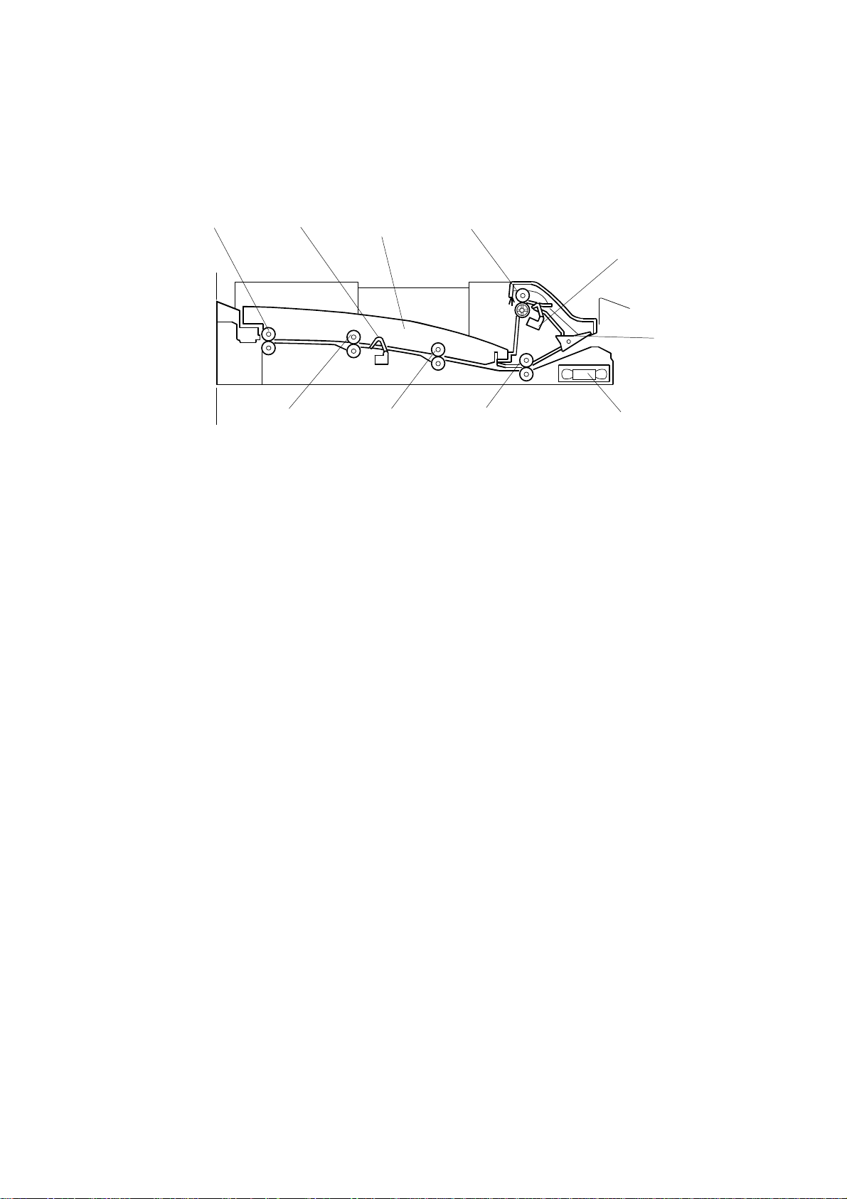
1.2 MECHANICAL COMPONENT LAYOUT
8109
B417V500.WMF
1. Upper Exit Roller
2. Tray Exit Sensor
3. Junction Gate
4. Cooling Fan
5. 1st Transport Roller
1
2
567
4
6. 2nd Transport Roller
7. 3rd Transport Roller
8. Left Exit Roller
9. Relay Sensor
10. Paper Tray
3
B417-2
Page 4

10 August, 2001 ELECTRICAL COMPONENT LAYOUT
1.3 ELECTRICAL COMPONENT LAYOUT
6
7
8
1. Left Guide Switch
2. Right Guide Switch
3. Junction Gate Solenoid
B417V501.WMF
5. Cooling Fan Motor
6. Relay Sensor
7. Bridge Unit Drive Motor
5
4
3
2
1
4. Tray Exit Sensor
8. Bridge Unit Control Board
Options
B417-3
Page 5

ELECTRICAL COMPONENT DESCRIPTION 10 August, 2001
1.4 ELECTRICAL COMPONENT DESCRIPTION
Symbol Name Function Index No.
Motors
M1 Cooling Fan Cools the transport unit. 5
M2 Drive Motor Drives the bridge unit. 7
Sensors
S1 Tray Exit Checks for misfeeds. 4
S2 Relay Checks for misfeeds. 6
Switches
SW2 Right Guide Detects when the right guide is opened. 2
SW3 Left Guide Detects when the left guide is opened. 1
Solenoids
Moves the junction gate to direct the
paper to the upper tray (on top of the
bridge unit) or to the finisher.
Controls the bridge unit.
3
8
SOL1
PCBs
PCB1
Junction Gate
Bridge Unit Control
Board
B417-4
Page 6

10 August, 2001 DRIVE LAYOUT
1.5 DRIVE LAYOUT
5
4
6
3
1
1. Left Exit Roller
2. 2nd Transport Roller
3. 1st Transport Roller
4. Upper Exit Roller
5. 3rd Transport Roller
6. Bridge Unit Drive Motor
2
B417V502.WMF
B417-5
Options
Page 7

JUNCTION GATE MECHANISM 10 August, 2001
2. DETAILED DESCRIPTION
2.1 JUNCTION GATE MECHANISM
[A]
[D]
[B]
[C]
B417D104.WMF
The junction gate [B] directs any paper reaching the bridge unit to either the upper
tray (on top of the bridge unit) or to the finisher, depending on which has been
selected.
If the junction gate solenoid [A] has been activated, the junction gate [B] points
downward and directs the paper to the upper tray [D] (dotted line path in
illustration). When the solenoid is off, the junction gate points upward and the
paper is fed out to the finisher [C] by the transport and exit rollers (solid line).
B417-6
Page 8

10 August, 2001 BRIDGE UNIT DRIVE MOTOR REPLACEMENT
3. REPLACEMENT AND ADJUSTMENT
NOTE: When taking apart the bridge unit, first take the unit out of the copier.
3.1 BRIDGE UNIT DRIVE MOTOR REPLACEMENT
[D]
[C]
B417R103.WMF
1. Remove the bridge unit from the copier. (See the Installation Procedure in the
base copier manual.)
2. Remove the rear cover [C] (2 screws).
3. Remove the bridge unit drive motor [D] (2 screws, 1 connector).
Options
B417-7
Page 9

TRAY EXIT SENSOR REPLACEMENT 10 August, 2001
3.2 TRAY EXIT SENSOR REPLACEMENT
[A]
[C]
[B]
B417R104.WMF
1. Remove the bridge unit from the copier. (See the Installation Procedure in the
base copier manual.)
2. Remove the rear cover (2 screws). See Bridge Unit Drive Motor Replacement.
3. Remove the paper tray [A].
4. Remove the exit guide [B] (2 screws).
5. Remove the tray exit sensor [C] (1 connector).
3.3 RELAY SENSOR REPLACEMENT
[D]
B417R102.WMF
1. Remove the bridge unit from the copier. (See the Installation Procedure in the
base copier manual.)
2. Stand the bridge unit up as shown in the illustra tion and remove the sensor [D].
B417-8
 Loading...