

Page 1

BY-PASS
(Machine Code: A689)
Page 2

26 March 1998 SPECIFICATIONS
1 OVERALL MACHINE INFORMATION
1.1 SPECIFICATIONS
Paper Size
:
Standard sizes
A6 lengthwise to A3
HLT lengthwise to DLT
Non-standard sizes
Width: 100 to 305 mm
Length: 148 to 432 mm
Paper Weight: 52 g/m
2
~ 157 g/m2, 16 lb ~ 42 lb
Tray Capacity: 50 sheets (80 g/m
Paper Feed System: FRR
2
, 20 lb)
A689-1
Options
Page 3
MECHANICAL COMPONENT LAYOUT 26 March 1998
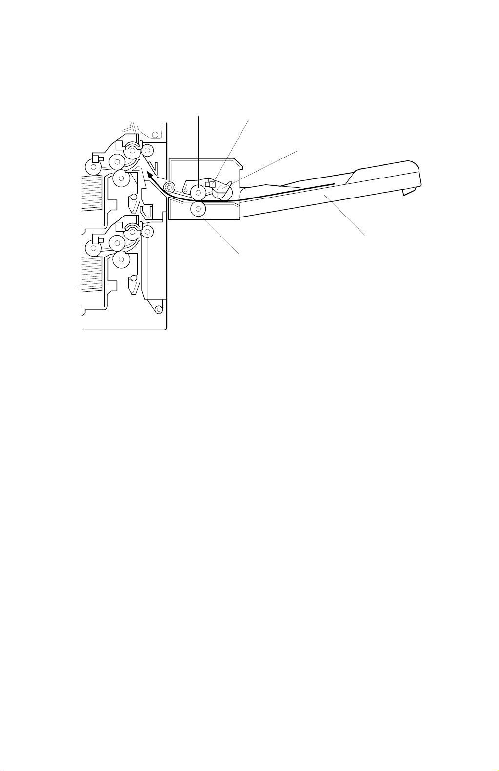
1.2 MECHANICAL COMPONENT LAYOUT
1. Paper Feed Roller
1
2
3
4
5
A689V500.WMF
4. By-pass Tray
2. Paper End Sensor
3. Pick-up Roller
5. Separation Roller
A689-2
Page 4
26 March 1998 ELECTRICAL COMPONENT LAYOUT
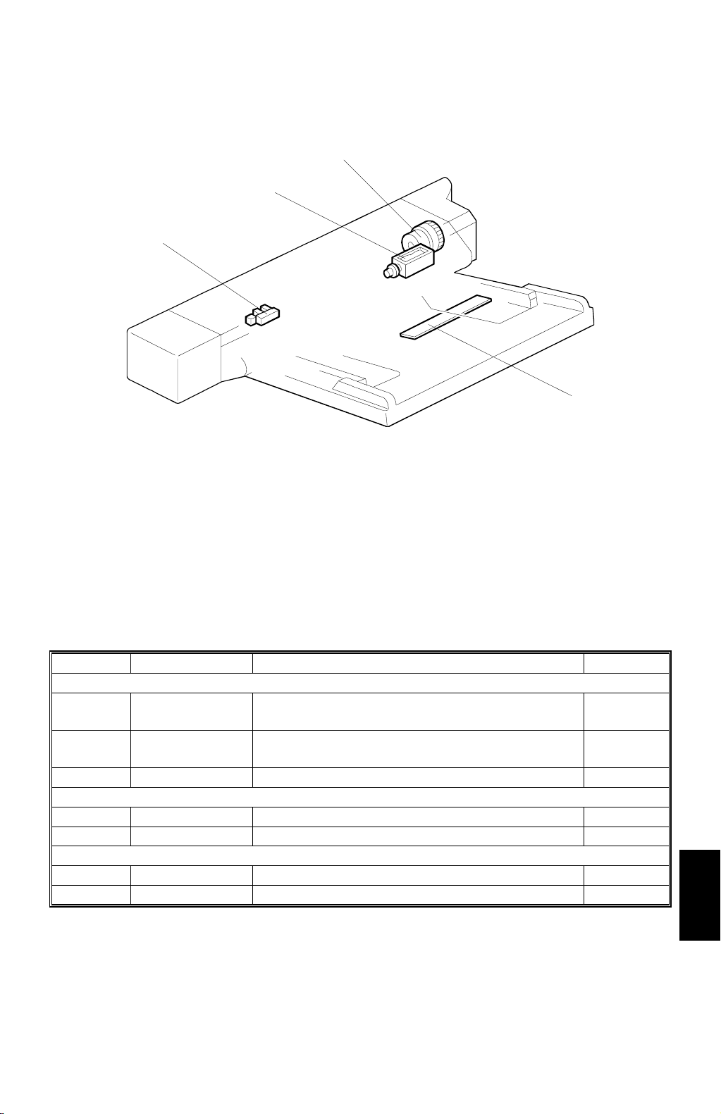
1.3 ELECTRICAL COMPONENT LAYOUT
3
2
1
4
A689V501.WMF
1. Paper End Sensor
2. Pick-up Solenoid
3. Paper Feed Clutch
4. Paper Size Sensor Board
1.4 ELECTRICAL COMPONENT DESCRIPTION
Symbol Name Function Index No.
Sensors
S1
S2
Solenoids
SOL1 Pick-up Moves the pick-up roller to contact the paper. 2
Magnetic Clutches
MC1 Paper Feed Starts paper feed from the by-pass tray. 3
Paper End Informs the copier when the by-pass tray runs
out of paper.
Paper Size
Sensor Board
Detects the paper width.
1
4
Options
A689-3
Page 5

BASIC OPERATION 26 March 1998
2 DETAILED DESCRIPTIONS
2.1 BASIC OPERATION
[A]
A689D500.WMF
[C]
[D]
[E]
A689D501.WMF
This unit is directly driven by the copier through gear [A].
When the print key is pressed, the pick-up solenoid [B] turns on and the pick-up
roller [C] moves onto the paper.
When the by-pass tray runs out of paper, the paper end feeler [D] drops int o the
cutout in the by-pass tray and the paper end sensor [E] is acti vated.
[B]
A689-4
Page 6

26 March 1998 PAPER SIZE DETECTION
2.2 PAPER SIZE DETECTION
[A]
A689D502.WMF
1/2
"11"
A3 B4 A4L B5L A5L B6L
5
1/2
"8
A689D503.WMF
The paper size sensor board [A] monitors the paper width. The rear side fence is
connected to the terminal plate. The pattern for each paper width is unique.
Therefore, the copier determines which paper has been placed in the by-pass tray
by the signal output from the board. However, the copier will not determine the
paper length from the bypass tray hardware.
Options
A689-5
Page 7

COVER REPLACEMENT 26 March 1998
3 REPLACEMENT AND ADJUSTMENT
3.1 COVER REPLACEMENT
[D]
[A]
[B]
[C]
Rear Cover
1. Remove the rear cover [A] (1 screw).
Front Cover
1. Remove the front cover [B] (1 screw).
Hinge Cover
1. Remove the hinge cover [C] (1 screw).
Upper Cover
- No duplex unit -
1. Remove the upper cover [D] (2 screws).
- With duplex unit -
1. Remove the hinge cover.
2. Open the duplex unit.
A689R500.WMF
3. Remove two screws for the upper cover.
4. Close the duplex unit and pull out the upper cover.
A689-6
Page 8

26 March 1998 PAPER FEED AND PICK-UP ROLLER REPLACEMENT
3.2 PAPER FEED AND PICK-UP ROLLER REPLACEMENT
[C]
[B]
[A]
1. Remove the upper cover.
2. Lift up the paper end feeler [A].
NOTE:
When lifted, the paper end feeler locks into positi on. Therefore, make
sure to move it back to its original position bef ore reinst al ling the upper
cover.
Paper Feed Roller
3. Replace the paper feed roller [B] (1 snap ring).
Pick-up Roller
3. Replace the pick-up roller [C].
A689R501.WMF
A689-7
Options
Page 9

SEPARATION ROLLER REPLACEMENT 26 March 1998
3.3 SEPARATION ROLLER REPL ACEMENT
[A]
A689R502.WMF
1. Close the by-pass table.
2. Remove the separation roller [A] from the bott om (1 snap ring).
A689-8
Page 10

26 March 1998 PAPER END SENSOR AND PICK-UP SOLENOID REPLACEMENT
3.4 PAPER END SENSOR AND PICK- UP SOLENOID
REPLACEMENT
[C]
[B]
[A]
1. Remove the upper cover.
Paper End Sensor
2. Lift up the paper end feeler [A].
NOTE:
When lifted, the paper end feeler locks into positi on. Therefore, make
sure to move it back to its original position bef ore reinst al ling the upper
cover.
A689R503.WMF
3. Replace the paper end sensor [B] (1 connector).
Pick-up Solenoid
2. Remove the pick-up solenoid [C] (1 screw, 1 spring, 1 connector).
A689-9
Options
Page 11

PAPER SIZE SENSOR BOARD REPLACEMENT 26 March 1998
3.5 PAPER SIZE SENSOR BOARD REPLACEMENT
[C]
[B]
[A]
A689R504.WMF
1. Release the hook [A] and remove the paper tray [B] (1 connector).
2. Replace the paper size sensor board [C].
NOTE:
When removing the paper size sensor board, be careful not to break its
hook.
A689-10
Page 12

26 March 1998 BY-PASS TABLE REMOVAL
3.6 BY-PASS TABLE REMOVAL
[A]
[B]
[C]
1. Remove the hinge cover.
2. Disconnect the connector [A].
3. Remove the two screws [B]
4. Hold the spring bracket and remove the by-pass table [C].
CAUTION:
Pressure is applied to the spring bracket, so when removing the bypass tray, hold the spring bracket by hand as shown.
A689R505.WMF
Options
A689-11
Page 13

PAPER FEED CLUTCH REPLACEMENT 26 March 1998
3.7 PAPER FEED CLUTCH REPLACEMENT
[A]
A689R506.WMF
1. Remove the by-pass tray.
2. Remove the paper feed unit [A] (2 screws, 1 connector).
3. Remove the rear bracket [B] (3 screws, 1 clip, 1 bushing).
4. Replace the paper feed clutch [C] (1 connector)
[C]
[B]
A689R507.WMF
A689-12
 Loading...