

Page 1
G144/G145
SERVICE MANUAL
002540MIU
Page 2

Page 3

SERVICE MANUAL
G144/G145
Page 4

Page 5

G144/G145
SERVICE MANUAL
002540MIU
Page 6

Page 7

A
f
r
It is the reader's responsibility when discussing the information contained
within this document to maintain a level of confidentiality that is in the best
interest of Ricoh Corporation and its member companies.
NO PART OF THIS DOCUMENT MAY BE REPRODUCED IN ANY
FASHION AND DISTRIBUTED WITHOUT THE PRIOR
PERMISSION OF RICOH CORPORATION.
ll product names, domain names or product illustrations, including
desktop images, used in this document are trademarks, registered
trademarks or the property of their respective companies.
They are used throughout this book in an informational or editorial fashion
only and for the benefit of such companies. No such use, or the use o
any trade name, or web site is intended to convey endorsement or othe
affiliation with Ricoh products.
2005 RICOH Corporation. All rights reserved.
Page 8

Page 9

p
r
g
l
y
p
WARNING
The Service Manual contains information
regarding service techniques, procedures,
rocesses and spare parts of office equipment
distributed by Ricoh Corporation. Users of this
manual should be either service trained o
certified by successfully completing a Ricoh
Technical Training Program.
Untrained and uncertified users utilizin
information contained in this service manual to
repair or modify Ricoh equipment risk persona
injury, damage to property or loss of warrant
rotection.
Ricoh Corporation
Page 10

Page 11

LEGEND
PRODUCT CODE COMPANY
G144 ----- ----- BP20 ----G145 ----- ----- BP20N -----
GESTETNER LANIER RICOH SAVIN
DOCUMENTATION HISTORY
REV. NO. DATE COMMENTS
*
10/2005 Original Printing
Page 12

Page 13

G144/G145
TABLE OF CONTENTS
INSTALLATION
1. INSTALLATION............................................................................ 1-1
1.1 INSTALLATION PROCEDURE .................................................................1-1
PREVENTIVE MAINTENANCE
2. PREVENTIVE MAINTENANCE.................................................... 2-1
2.1 PM INTERVALS ........................................................................................2-1
REPLACEMENT AND ADJUSTMENT
3. REPLACEMENT AND ADJUSTMENT ........................................ 3-1
3.1 GENERAL PRECAUTIONS.......................................................................3-1
3.1.1 SERVICING THE MACHINE ............................................................ 3-1
3.1.2 RELEASING PLASTIC LATCHES....................................................3-1
3.2 COVERS ...................................................................................................3-2
3.2.1 FRONT COVER................................................................................3-2
3.2.2 BYPASS COVER..............................................................................3-3
3.2.3 REAR COVER.................................................................................. 3-4
3.2.4 TOP COVER ....................................................................................3-6
3.2.5 RIGHT SIDE COVER .......................................................................3-7
3.2.6 LEFT SIDE COVER..........................................................................3-8
3.2.7 MIDDLE COVER ..............................................................................3-9
3.3 EXIT ROLLER .........................................................................................3-10
3.4 ENGINE SHIELD ASSEMBLY AND EXIT BOARD .................................3-11
3.4.1 ENGINE SHIELD............................................................................ 3-11
3.4.2 EXIT BOARD..................................................................................3-13
3.5 SMPS ...................................................................................................... 3-14
3.6 FUSING UNIT..........................................................................................3-17
3.6.1 FUSING UNIT ASSEMBLY ............................................................3-17
3.6.2 THERMOSTAT...............................................................................3-18
3.6.3 FUSING LAMP ...............................................................................3-19
3.6.4 STRIPPER PAWLS ........................................................................3-20
Reassembling the Fusing Unit ............................................................3-21
Note. ...................................................................................................3-22
3.6.5 THERMISTOR................................................................................ 3-23
3.7 UNPLUG FAN .........................................................................................3-24
3.8 LASER SCANNING UNIT .......................................................................3-25
3.9 DRIVE UNIT ............................................................................................3-27
3.10 TRANSFER UNIT..................................................................................3-28
SM i G144/G145
Page 14

3.11 BYPASS TRAY UNIT AND FEED ROLLER..........................................3-30
3.11.1 BYPASS TRAY UNIT ...................................................................3-30
3.12 PICK-UP ASSEMBLY AND SOLENOID................................................ 3-32
Pick-up Roller and By-pass Pick-up Roller .........................................3-34
Paper Feed Unit Pick-up Roller ..........................................................3-34
By-pass pick-up roller .........................................................................3-35
TROUBLESHOOTING
4. TROUBLESHOOTING ................................................................. 4-1
4.1 PAPER PATH............................................................................................4-1
4.1.1 PAPER JAM CONDITIONS..............................................................4-2
Jam0 .....................................................................................................4-2
Jam1 .....................................................................................................4-2
Jam2 .....................................................................................................4-3
4.2 CLEARING PAPER JAMS ........................................................................4-4
4.2.1 JAM2 (PAPER EXIT AREA) .............................................................4-4
4.2.2 JAM0 (PAPER FEED AREA)............................................................4-6
4.2.3 JAM1 (TONER CARTRIDGE AREA)................................................4-7
4.2.4 TIPS TO AVOID PAPER JAMS........................................................4-8
4.3 SAMPLE PATTERN .................................................................................. 4-9
4.3.1 PRINTING A DEMO PAGE AND CONFIGURATION PAGE ............4-9
4.3.2 PRINTING A CLEANING SHEET................................................... 4-10
4.4 OPERATION PANEL DISPLAY...............................................................4-10
4.5 PERIODIC DEFECTIVE IMAGE..............................................................4-10
4.6 PRINTOUT PROBLEMS .........................................................................4-11
4.6.1 INCORRECT PRINT POSITION ....................................................4-11
4.6.2 VERTICAL BLACK LINE AND BAND .............................................4-11
4.6.3 VERTICAL WHITE LINE.................................................................4-11
4.6.4 HORIZONTAL BLACK BANDS ......................................................4-12
4.6.5 BLACK/WHITE SPOTS ..................................................................4-12
4.6.6 LIGHT IMAGE ................................................................................4-12
4.6.7 DARK/BLACK IMAGE ....................................................................4-13
4.6.8 UNEVEN DENSITY ........................................................................4-13
4.6.9 BACKGROUND..............................................................................4-13
4.6.10 GHOST 1......................................................................................4-14
4.6.11 GHOST 2......................................................................................4-14
4.6.12 GHOST 3......................................................................................4-14
4.6.13 GHOST 4......................................................................................4-15
4.6.14 STAINS ON FRONT OF PAGE ....................................................4-15
4.6.15 STAINS ON BACK OF PAGE.......................................................4-15
4.6.16 BLANK PAGE 1............................................................................4-15
4.6.17 BLANK PAGE 2............................................................................4-16
4.7 PAPER FEED PROBLEMS..................................................................... 4-17
4.7.1 INCORRECT PRINT POSITION ....................................................4-17
4.7.2 JAM 0 .............................................................................................4-17
4.7.3 JAM 1 .............................................................................................4-17
4.7.4 JAM 2 .............................................................................................4-18
G144/G145 ii SM
Page 15

4.7.5 MULTI-FEEDING............................................................................4-18
4.7.6 PAPER ROLLED IN THE FUSING UNIT........................................4-18
4.7.7 PAPER REMAINS ROLLED ON THE OPC DRUM ........................4-19
4.8 SET MALFUNCTIONS ............................................................................4-20
4.8.1 ALL LEDS BLINK (FUSING ERROR).............................................4-20
4.8.2 ALL LEDS BLINK (SCAN ERROR) ................................................4-20
4.8.3 PAPER EMPTY ..............................................................................4-20
4.8.4 PAPER EMPTY WITHOUT INDICATION.......................................4-20
4.8.5 FUSING GEAR MELTS (OVERHEATS).........................................4-21
4.8.6 COVER OPEN................................................................................4-21
4.8.7 NO ERROR LAMP WHEN COVER IS OPENED ...........................4-21
4.8.8 NO POWER....................................................................................4-22
4.8.9 PRINTED VERTICAL LINES ARE CURVED..................................4-22
4.9 TONER CARTRIDGE.............................................................................. 4-23
4.9.1 TONER CARTRIDGE PRECAUTIONS ..........................................4-23
4.9.2 REDISTRIBUTING TONER............................................................4-23
4.9.3 TONER CARTRIDGE DETAILS .....................................................4-25
4.10 SOFTWARE PROBLEMS .....................................................................4-28
4.10.1 PRINTER DOES NOT OPERATE CORRECTLY 1 ......................4-28
4.10.2 PRINTER DOES OPERATE CORRECTLY 2............................... 4-29
4.10.3 ABNORMAL PRINTING ...............................................................4-30
4.10.4 SPOOL ERROR ...........................................................................4-30
How to Delete Data in the Spool Manager..........................................4-30
SERVICE PROGRAM MODE
5. SERVICE PROGRAM MODE....................................................... 5-1
5.1 FIRMWARE DOWNLOAD......................................................................... 5-1
5.1.1 DOWNLOAD PROCEDURE.............................................................5-1
DOS Command mode...........................................................................5-1
EWS (Embedded Web Server) mode ...................................................5-2
5.1.2 FIRMWARE RECOVERY PROCEDURE .........................................5-4
DETAILED DESCRIPTIONS
6. DETAILED DESCRIPTIONS ........................................................ 6-1
6.1 MACHINE OVERVIEW..............................................................................6-1
6.1.1 FRONT VIEW ...................................................................................6-1
6.1.2 REAR VIEW .....................................................................................6-2
6.1.3 OPERATION PANEL........................................................................6-3
On Line/Error Button............................................................................. 6-3
Toner Save Button................................................................................6-4
On Line/Error Button and Toner Save Button .......................................6-4
Cancel Button .......................................................................................6-4
6.2 MACHINE OVERVIEW..............................................................................6-5
6.2.1 FIRMWARE ......................................................................................6-5
6.2.2 PRINT ENGINE ................................................................................6-5
SM iii G144/G145
Page 16

Paper Feed Mechanism........................................................................6-5
Drive Mechanism ..................................................................................6-5
Laser Scanning Unit..............................................................................6-5
Development Unit .................................................................................6-5
Transfer Unit .........................................................................................6-5
Fusing Unit............................................................................................6-5
Electrical Components (PBA) ...............................................................6-6
6.3 SYSTEM LAYOUT ....................................................................................6-7
6.3.1 PAPER FEED UNIT..........................................................................6-8
Paper Separation Method .....................................................................6-8
Paper Tray ............................................................................................6-8
Pick-up roller.........................................................................................6-8
By-pass tray..........................................................................................6-8
Optional Paper Feed Unit .....................................................................6-8
6.3.2 TRANSFER UNIT............................................................................. 6-9
6.3.3 DRIVE...............................................................................................6-9
6.3.4 FUSING UNIT...................................................................................6-9
Thermostat............................................................................................6-9
Thermistor.............................................................................................6-9
Hot Roller..............................................................................................6-9
Pressure Roller .....................................................................................6-9
Safety Features ..................................................................................6-10
Safety Devices....................................................................................6-10
6.3.5 LASER SCANNNING UNIT (LSU).................................................. 6-10
6.3.6 TONER CARTRIDGE .....................................................................6-11
6.3.7 NEW AIO DETECTION ..................................................................6-12
6.3.8 TONER END DETECTION.............................................................6-12
6.4 ASIC(SPGP)............................................................................................6-13
6.4.1 MEMORY .......................................................................................6-13
6.4.2 FLASH MEMORY...........................................................................6-13
6.4.3 SDRAM...........................................................................................6-14
6.4.4 SENSOR INPUT CIRCUIT ............................................................. 6-15
Paper Empty Sensor...........................................................................6-15
By-pass Tray Sensor ..........................................................................6-15
Paper Feeding ....................................................................................6-15
Paper Exit Sensor...............................................................................6-15
Cover Open Sensor ............................................................................6-15
DC Fan/Solenoid Driving Circuit .........................................................6-15
Motor Drive Circuit ..............................................................................6-16
Transfer ..............................................................................................6-16
Fusing .................................................................................................6-16
LSU.....................................................................................................6-17
6.5 SMPS AND HVPS ...................................................................................6-18
6.5.1 HVPS (HIGH VOLTAGE POWER SUPPLY) ..................................6-19
1. Transfer High Voltage (THV+) ..........................................................6-19
2. Charge Voltage (MHV) .....................................................................6-19
3. Cleaning Voltage (THV-)...................................................................6-19
4. Developing Voltage (DEV)................................................................6-20
5. Supply...............................................................................................6-20
G144/G145 iv SM
Page 17

6.5.2 SMPS (SWITCHING MODE POWER SUPPLY) ............................6-21
1. AC Input............................................................................................6-21
2. Rated Output Power .........................................................................6-21
3. Consumption Power .........................................................................6-21
6.6 ENGINE...................................................................................................6-22
6.6.1 PAPER FEED.................................................................................6-22
SPECIFICATIONS
SPECIFICATIONS............................................................................. 7-1
1.1 GENERAL SPECIFICATIONS...................................................................7-1
1.2 CONTROLLER ..........................................................................................7-2
1.3 SOFTWARE SPECIFICATIONS ...............................................................7-3
1.4 OPTIONAL UNIT SPECIFICATIONS ........................................................7-4
APPENDIX
BLOCK DIAGRAM ............................................................................ 8-1
CONNECTION DIAGRAM................................................................. 8-2
SM v G144/G145
Page 18

Page 19
PRECAUTIONS
In order to prevent accidents and damage to the equipment, please read the
following precautions before you service the machine.
SAFETY WARNING
1. Only qualified service engineers should service this machine. The high voltages
and lasers inside this product should be approached with caution.
2. Use only approved replacement parts. There are no user serviceable parts
inside the printer. Do not make any unauthorized changes or additions to the
printer. This could cause the printer to malfunction and create electric shock or
fire hazards.
3. Laser Safety Statement: This machine is certified in the U.S. to conform to the
requirements of DHHS 21 CFR, chapter 1 Subchapter J for Class 1(1) laser
products and elsewhere. It is certified as a Class I laser product conforming to
the requirements of IEC 825. Class I laser products are not considered to be
hazardous. The laser system and printer are designed to prevent access to
laser radiation during normal operation, user maintenance, or prescribed
service activities.
NOTE: Never operate or service the printer with the protective cover removed from
Laser/Scanner assembly. The reflected beam can damage your eyes.
When using this product, these basic safety precautions should always be
followed to reduce risk of fire, electric shock, and injury to persons.
WARNING
Page 20

SAFETY PRECAUTIONS
TOXIC MATERIALS
This product contains toxic materials that could cause illness if ingested.
1. If the LCD control panel is damaged, it is possible for the liquid inside to leak
out. This liquid is toxic and contact with skin should be avoided. Wash any
splashes from eyes or skin immediately for 15 minutes under running water,
and contact a doctor. See a doctor immediately if the liquid gets into the mouth
or is swallowed.
2. Please keep toner cartridges away from children. The toner powder contained
with the toner cartridge may be harmful if swallowed. Contact a doctor
immediately if toner powder is swallowed.
ELECTRIC SHOCK AND FIRE SAFETY PRECAUTIONS
Failure to follow the following instructions could cause electric shock or fire.
1. Use only the correct voltage. Failure to do so could damage the printer and
potentially cause a fire or electric shock.
2. Use only the power cable supplied with this machine. Use of an incorrectly
specified cable could cause the cable to overheat and potentially cause a fire.
3. Do not overload the power socket. This could lead to overheating of the cables
inside the wall and could lead to a fire.
4. Do not allow water or other liquids to spill into the printer. This can cause
electric shock. Do not let paper clips, pins, or other foreign objects fall into the
printer. These could cause a short circuit leading to an electric shock or fire
hazard. If foreign objects fall into the machine, power off the machine
immediately and disconnect the power cord from the wall outlet.
5. Never touch the plugs on either end of the power cable with wet hands. This
can cause electric shock.
6. Remove the power plug from the wall socket when servicing the printer.
7. Use caution when you insert or remove the power plug. The power plug must
be inserted completely. Otherwise, a poor contact could cause overheating and
lead to a fire. (When removing the power plug, grip the plug firmly and pull. Do
not pull the power cable out by pulling on the cord itself.)
8. Do not allow the power cable to become twisted or bent sharply around
corners. Do not place objects on top of the power cable. If the power cable is
damaged, it could overheat and cause a fire. Exposed cables could cause an
electric shock. Replace a damaged power cable immediately. Do not reuse or
repair a damaged cable. Some chemicals can also attack the coating on the
power cable, weakening the cover or exposing cables. This can cause fire and
shock risks.
Page 21

9. Ensure that the power sockets and plugs are not cracked or broken in any way.
Repair such defects immediately. Take care not to cut or damage the power
cable or plugs when moving the machine.
10. Use caution during thunder or lightening storms. Disconnect the machine from
the power source when such weather conditions are expected. Do not touch
the machine or the power cord if it is still connected to the wall socket in these
weather conditions.
11. Avoid damp or dusty areas. Install the machine in a clean, well-ventilated
location. Do not position the machine near a humidifier. Dampness and dust
build-up inside the machine can lead to overheating and cause a fire.
12. Do not position the machine in direct sunlight. This will cause the temperature
inside the machine to rise, possibly leading to machine failure and, in extreme
conditions, could lead to a fire.
13. Do not insert metal objects into the machine through the ventilator fan or other
part of the casing. This could create contact with a high voltage conductor
inside the machine and cause an electric shock.
HANDLING PRECAUTIONS
The following instructions are for your own personal safety, to avoid injury and to
prevent damage to the machine.
1. Ensure that machine is installed on a level surface, capable of supporting its
weight. Failure to do so could cause the machine to tip or fall.
2. Avoid placing fingers or hair in close proximity to any rollers, gears, or fans
within this machine while the machine is in operation.
3. Do not place any small metal objects, containers of water, chemicals, or other
liquids close to the machine. This can cause damage, shock, or fire if spilled
into the machine.
4. Do not install the machine in areas with high dust or moisture levels, beside
open windows, or close to a humidifier or heater.
5. Do not place candles, burning cigarettes, etc. on the machine. A fire may occur.
Page 22
ASSEMBLY/DISASSEMBLY PRECAUTIONS
Replace with approved parts only. Take care to note the exact location of parts and
the correct cable routing before you disassemble any part of the machine. Ensure
all parts and cables are replaced correctly. Perform the following procedures before
you disassemble the machine or replace any parts.
1. Check the contents of the machine
memory and make a note of any
user settings. These will be erased
if the main board or network card
is replaced.
2. Ensure that power is disconnected
before you service or replace any
electrical parts.
3. Disconnect printer interface cables
and power cables.
4. Use only approved spare parts.
Ensure that part number, product name,
voltages, current and/or temperature rating
are correct.
5. When removing or re-fitting any
parts, do not use excessive force
(especially when fitting screws into
plastic).
6. Take care not to drop any small
parts into the machine.
7. Handling of the OPC Drum:
• The OPC Drum can be damaged
if it is exposed to light.
• Take care not to expose the OPC
Drum either to direct sunlight, or
fluorescent light or incandescent
lighting. Exposure for as little as 5 minutes can damage the surface’s
photoconductive properties and will result in print quality degradation.
Remove the OPC Drum and store it in a black bag or other lightproof
container. Take care when working with the covers (especially the top cover),
since light can be admitted to the OPC area and can damage the OPC Drum.
• Take care not to scratch the green surface of OPC Drum Unit. If the green
surface of the Drum Cartridge is scratched or touched, the print quality will be
compromised.
CAUTION1.TIF
Caution2.tif
Page 23
ADDITIONAL SAFETY PRECAUTIONS
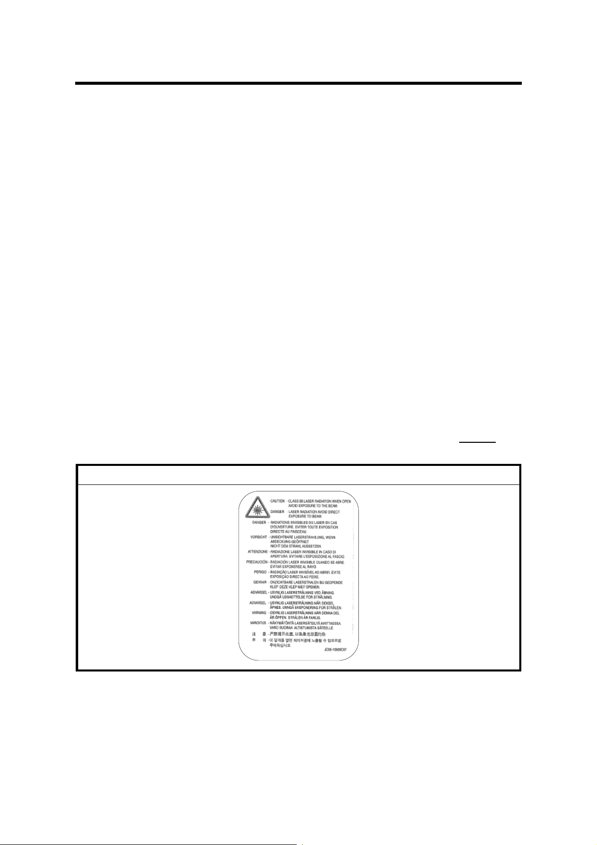
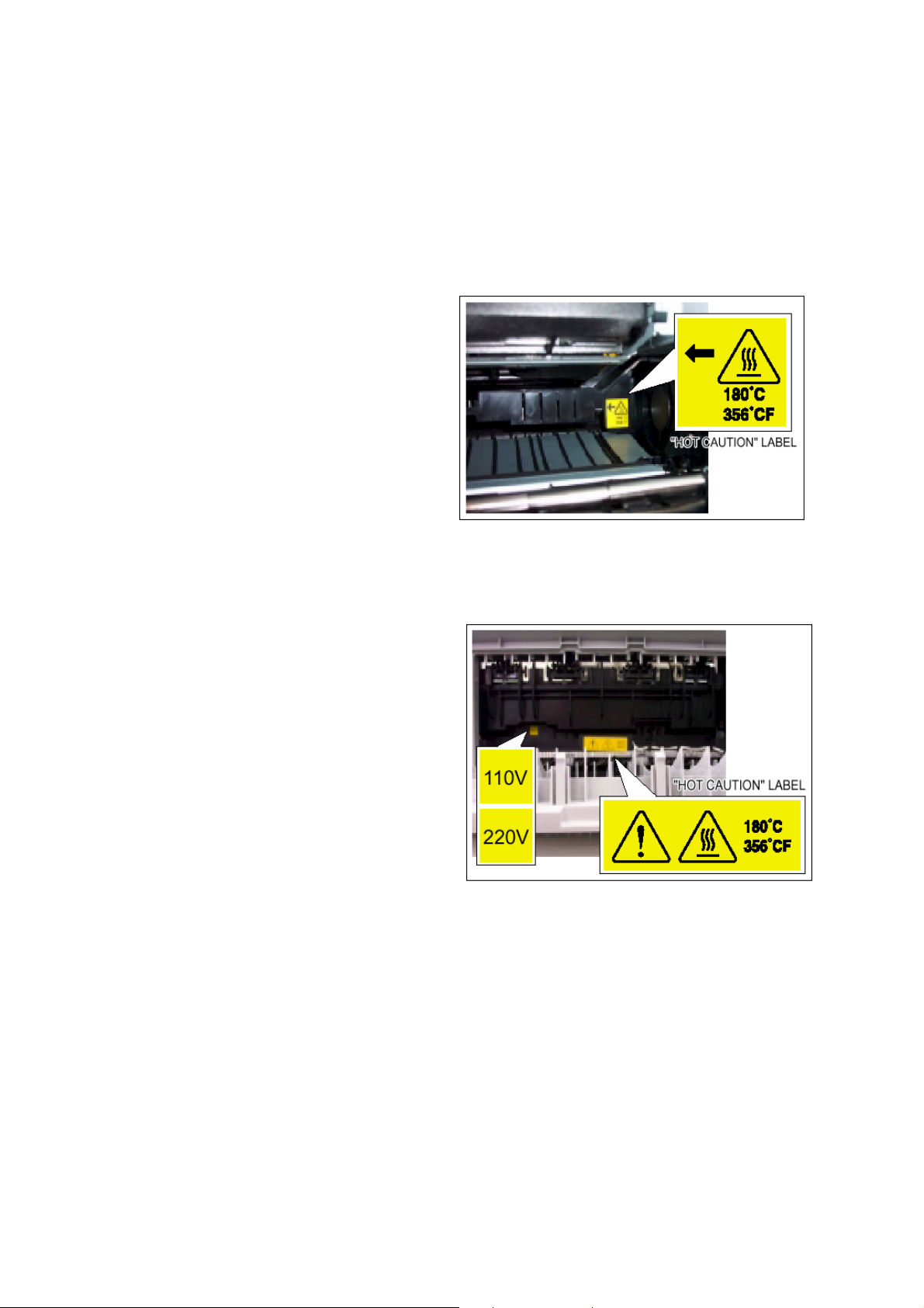
1. Use caution with high-temperature parts. The fusing unit operates at a high
temperature. Use caution when working on this area of the machine. Wait for
the fusing unit to cool down before disassembling it.
2. Do not place your fingers or hair near or into the rotating parts and
components.
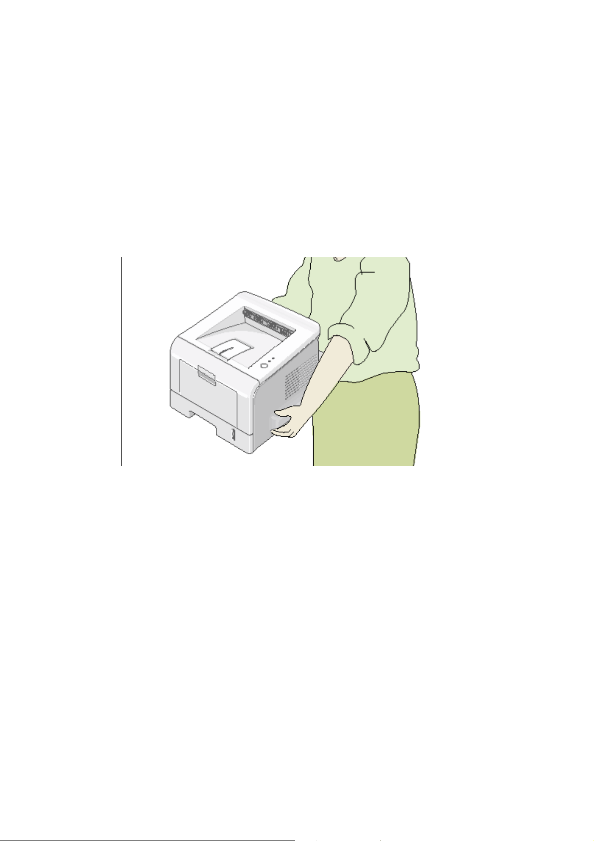
3. This machine weighs 12.7kg, including toner cartridge and cassette. Use safe
lifting and handling techniques. Use the lifting handles located on each side of
the machine. Back injury could result if you do not lift the unit carefully.
CAUTION3.TIF
4. Ensure the machine is installed safely on a level surface, capable of supporting
its weight. Failure to do so could cause the machine to tip or fall, possibly
causing personal injury or damaging the machine.
5. Do not install the machine on a sloping or unstable surface. After installation,
double-check that the printer is stable.
Page 24

ESD PRECAUTIONS
Certain semiconductor devices can be damaged by static electricity. Such
components are commonly called “Electrostatically Sensitive (ES) Devices”, or
ESDs. Examples of typical ESDs are: integrated circuits, some field effect
transistors, and semiconductor “chip” components. The techniques outlined below
should be strictly followed to help reduce the incidence of component damage
caused by static electricity.
CAUTION
Ensure that no power is applied to the chassis or circuit, and observe all other
safety precautions.
1. Immediately before handling a semiconductor component or semiconductorequipped assembly, drain any electrostatic charge on your body by touching a
known earth ground. Alternatively, employ a commercially available wrist strap
device, which must be removed for your personal safety reasons prior to
applying power to the unit under test.
2. After removing an electrical assembly equipped with ESDs, place the assembly
on a conductive surface, such as aluminum or copper foil, or conductive foam,
to prevent electrostatic charge buildup in the vicinity of the assembly.
3. Use only a grounded-tip soldering iron to solder or desolder ESDs.
4. Use only an “anti-static” solder removal device. Some solder removal devices
not classified as “anti-static” can generate electrical charges sufficient to
damage ESDs.
5. Do not use Freon-propelled chemicals. When sprayed, these can generate
electrical charges sufficient to damage ESDs.
6. Do not remove a replacement ESD from its protective packaging until
immediately prior to installing it. Most replacement ESDs are packaged with all
leads shorted together by conductive foam, aluminum foil, or a comparable
conductive material.
7. Immediately before removing the protective shorting material from the leads of
a replacement ESD, touch the protective material to the chassis or circuit
assembly into which the device will be installed.
8. Maintain continuous electrical contact between the ESD and the assembly into
which it will be installed, until the ESD or assembly is completely plugged or
soldered into the circuit.
9. Minimize bodily motions when handling unpackaged replacement ESDs.
Normal motions, such as the brushing together of clothing fabric and lifting
one’s foot from a carpeted floor, can generate static electricity sufficient to
damage an ESD.
Page 25
INSTALLATION
PREVENTIVE MAINTENANCE
REPLACEMENT AND ADJUSTMENT
TROUBLESHOOTING
TAB
POSITION 1
TAB
POSITION 2
TAB
POSITION 3
TAB
POSITION 4
SERVICE PROGRAM MODE
DETAILED DESCRIPTIONS
SPECIFICATIONS
APPENDIX
TAB
POSITION 5
TAB
POSITION 6
TAB
POSITION 7
TAB
POSITION 8
Page 26

Page 27

INSTALLATION
Page 28

Page 29

INSTALLATION PROCEDURE
1. INSTALLATION
1.1 INSTALLATION PROCEDURE
Refer to the Operating Instructions for full installation procedures.
Installation
SM 1-1 G144/G145
Page 30

Page 31

PREVENTIVE MAINTENANCE
Page 32

Page 33

PM INTERVALS
2. PREVENTIVE MAINTENANCE
2.1 PM INTERVALS
The intervals shown below are for maintenance items.
Environmental conditions and machine use may affect these intervals. Adjust as
necessary.
NOTE: The intervals shown below are for reference only. The replacement
intervals noted here are expected to exceed machine life. However, if the
indicated interval is reached, that component should be replaced.
Component Replacement Cycle Done by
Pick-up Ass’y 150,000 pages Service
Printer
Transfer Roller 60,000 Pages Service
Fuser Unit 80,000 Pages Service
Preventive
Maintenance
SM 2-1 G144/G145
Page 34

Page 35

REPLACEMENT AND ADJUSTMENT
Page 36

Page 37

GENERAL PRECAUTIONS
3. REPLACEMENT AND ADJUSTMENT
This manual uses the following symbols.
: See or refer to : Screw : Connector: : C-clamp (snap ring) : E-
clamp
3.1 GENERAL PRECAUTIONS
• Use caution when you disassemble and reassemble components.
• Ensure that all cables are correctly routed. Check the correct cable routing
before you service the machine. Return all cables to their original position after
you service the machine.
3.1.1 SERVICING THE MACHINE
1. Make sure there are no documents stored in memory before you service the
machine.
2. Remove the toner cartridge before you disassemble parts.
Adjustment
Replacement
3. Unplug the power cord before you service the machine.
4. Use a flat, clean surface to service the machine.
5. Use only approved replacement parts. Machine function cannot be guaranteed
if unauthorized replacement parts are used.
6. Do not force plastic components. (Refer to 3.1.2)
7. Ensure that all components are in their correct positions.
3.1.2 RELEASING PLASTIC LATCHES
Many parts or covers in this machine are
held in place with plastic latches. The
latches break easily. Release them
carefully. To remove these parts, gently
press the hook end of the latch away from
the part to which it is latched.
G144R001.WMF
SM 3-1 G144/G145
Page 38

COVERS
3.2 COVERS
3.2.1 FRONT COVER
[B]
[A]
G144R002.WMF
G144R003.WMF
1. Pull the cassette [A] out of the printer.
2. Open the front cover [B] and push the toner cartridge down. Remove it from the
machine.
[C]
[D]
G144R004.WMF
G144R005.WMF
3. Pull inward to release the hinges [C].
4. Pull the front cover [D] away from the machine.
NOTE: To prevent damage to the toner cartridge, do not expose it to direct light for
more than a few seconds.
G144/G145 3-2 SM
Page 39

COVERS
3.2.2 BYPASS COVER
[A]
Adjustment
Replacement
1. Open the tray assembly [A].
2. Carefully bend the plastic
hinge supports toward the
center of the machine [B] to
release them from the guide
hooks.
3. Pull the by-pass tray [C]
outwards from the machine.
NOTE: A small amount of force
can be used when bending the
plastic hinges, but do not use
excessive force or the hinges
could be broken.
[C]
G144R006.WMF
[B]
G144R007.WMF
SM 3-3 G144/G145
Page 40

COVERS
3.2.3 REAR COVER
[A]
[B]
G144R031.WMF
1. Remove the 2 x and remove the
option cover assembly [A].
2. Remove the cover face [B] in the
direction of the arrow as shown above.
G144R032.WMF
G144/G145 3-4 SM
Page 41

COVERS
[C]
Adjustment
Replacement
G144R033.WMF
3. Remove the 2 x as shown above and snap the rear cover [C] out of the
machine.
SM 3-5 G144/G145
Page 42

COVERS
3.2.4 TOP COVER
Remove the following before removing the top cover:
Front Cover 3.2.1
Rear Cover 3.2.3
[A]
[B]
G144R008.WMF
1. Remove the 4 x as shown above. Lift the top cover [A] from the machine.
NOTE: Ensure that no damage is inflicted upon the exit roller [B] when removing
the top cover.
G144/G145 3-6 SM
Page 43

COVERS
3.2.5 RIGHT SIDE COVER
Remove the following before removing the right side cover:
Front Cover 3.2.1
Rear Cover 3.2.3
Top Cover 3.2.4
[A]
Adjustment
Replacement
[C]
[B]
G144R010.WMF
1. Remove the 2 x as shown above.
2. Release the top latch [A] and the three bottom latches [B] from the frame
assembly, in the direction of the arrow.
3. Remove the right side cover [C].
SM 3-7 G144/G145
Page 44

COVERS
3.2.6 LEFT SIDE COVER
Remove the following before removing the left side cover:
Front Cover 3.2.1
Rear Cover 3.2.3
Top Cover 3.2.4
[A]
[C]
[B]
G144R011.WMF
4. Remove the 2 x as shown above.
5. Release the top latch [A] and the three bottom latches [B] from the frame
assembly, in the direction of the arrow. Remove the left side cover [C].
G144/G145 3-8 SM
Page 45

COVERS
3.2.7 MIDDLE COVER
Remove the following before removing the middle cover:
Front Cover 3.2.1
Rear Cover 3.2.3
Top Cover 3.2.4
[A]
[B]
Adjustment
Replacement
[C]
G144R009.WMF
1. Remove the 2 x from the top of the middle cover [B] (screws are on the
inside).
2. Remove the 4 x from the base frame (screws are outside, at the back
bottom, center, left, and right).
3. Disconnect the operation panel harness [C] from the operation panel before
you remove the middle cover [B]. Ensure that you do not damage the hook [A].
SM 3-9 G144/G145
Page 46

EXIT ROLLER
3.3 EXIT ROLLER
Remove the following before removing the exit roller:
Front Cover 3.2.1
Rear Cover 3.2.3
Top Cover 3.2.4
Left and Right Side Cover 3.2.5, 3.2.6
[A]
[B]
[C]
[D]
G144R012.WMF
1. Gently pull the gear [A] and remove from the exit roller [B].
2. Pull on the latch [C] and slide the exit roller [B] out.
3. Remove 4 bushings [D] and 4 springs from the machine.
NOTE: The bushings contain grease. Be careful when removing them to prevent
this grease from reaching your clothing or the customer’s furnishings.
G144/G145 3-10 SM
Page 47

ENGINE SHIELD ASSEMBLY AND EXIT BOARD
3.4 ENGINE SHIELD ASSEMBLY AND EXIT BOARD
Remove the following before removing the engine shield and exit board:
Front Cover 3.2.1
Rear Cover 3.2.3
Top Cover 3.2.4
Left and Right Side Cover 3.2.5, 3.2.6
3.4.1 ENGINE SHIELD
Adjustment
Replacement
[A]
G144R013.JPG
Perform the following before removing the engine shield assembly.
NOTE: The SMPS shield is a safety shield that separates the high voltage area
from the rest of the IC chips.
1. Release 1 x (black arrow) from the SMPS shield [A]. Do not remove the
shield at this time.
SM 3-11 G144/G145
Page 48

ENGINE SHIELD ASSEMBLY AND EXIT BOARD
2. Turn the machine on its side and
remove the 12 x from the engine
shield assembly [B].
NOTE: All screws must be removed
before the safety shield can
be removed.
3. Unplug 5x from the operation
panel, fan, and fusing unit.
4. Turn the machine back upright and
remove the SMPS shield [A].
5. Remove the engine shield assembly
[B] from the machine.
[B]
G144R013.WMF
G144/G145 3-12 SM
Page 49

ENGINE SHIELD ASSEMBLY AND EXIT BOARD
3.4.2 EXIT BOARD
[A]
Adjustment
Replacement
1. Remove the 2 x as shown above.
2. Remove the exit board [A].
G144R014.WMF
SM 3-13 G144/G145
Page 50

SMPS
3.5 SMPS
Remove the following before removing the SMPS:
Front Cover 3.2.1
Rear Cover 3.2.3
Top Cover 3.2.4
Left and Right Side Cover 3.2.5, 3.2.6
[B] [C]
[A]
G144R015.WMF
1. Unplug one wire [A].
2. Remove the 3 x and remove the inlet bracket [B].
3. Remove the 2 x and remove the network board [C].
G144R016.WMF
G144/G145 3-14 SM
Page 51

SMPS
[D]
G144R017.WMF
Adjustment
Replacement
4. Unplug the engine harness [D].
[E]
G144R018.WMF
5. Remove 2 x from the IEEE1284 port and the main PBA [E].
SM 3-15 G144/G145
Page 52

SMPS
[F]
G144R019.WMF
6. Remove 6 x and remove the SMPS [F].
NOTE: If you need only to remove the optional memory units or the network card,
remove the optional cover only. 3.2.3
G144/G145 3-16 SM
Page 53

FUSING UNIT
3.6 FUSING UNIT
Remove the following before removing the fusing unit:
Rear Cover 3.2.3
3.6.1 FUSING UNIT ASSEMBLY
NOTE: Perform the following procedure only if it is necessary to remove the entire
fusing unit assembly. Otherwise, use the individual component procedures.
Adjustment
Replacement
1. Unplug the 2 x from the main PBA and the SMPS.
2. Remove 4 x . Remove the fusing unit assembly [A].
[A]
G144R020.WMF
SM 3-17 G144/G145
Page 54

FUSING UNIT
3.6.2 THERMOSTAT
[B]
G144R021.WMF
3. Remove the 2 x . Remove the thermostat [B].
NOTE: Both screws have a nut and a bolt.
G144/G145 3-18 SM
Page 55

FUSING UNIT
3.6.3 FUSING LAMP
[D]
[C]
G144R022.WMF
4. Remove the 2 x securing the fusing lamp [C].
NOTE: Both screws have a nut and a bolt.
5. Slide the fusing lamp [C] out from the hot roller [D] in the direction of the arrow
as shown above.
Adjustment
Replacement
SM 3-19 G144/G145
Page 56

FUSING UNIT
3.6.4 STRIPPER PAWLS
[C]
[A]
[B]
[A]: Remove the 4 x securing the fusing unit cover [A].
[B]: Remove the 2 x securing the guide input [B].
[C]: Disassemble the fusing unit.
G144R049.WMF
G144/G145 3-20 SM
Page 57

FUSING UNIT
Reassembling the Fusing Unit
The 4 x stripper pawls must be put in the correct position before you can
reassemble the fusing unit. Perform the following procedure before you put the
fusing unit back to the fusing unit assembly.
1. Snap the 4 x stripper pawls [A] out of the left and right side stripper pawl holder
slots (shown in white circles below).
[A]
Adjustment
Replacement
G144R901.TIF
2. Place the top part of the fusing unit onto the bottom part of the fusing unit.
3. Place the 4 x stripper pawls [A] back into the stripper pawl holder slots (shown
with two white arrows in the illustration below).
4. Push the sides of the stripper pawls securely into the stripper pawl holder slots.
5. Reassemble the rest of the fusing unit and set it back into the machine.
[A]
G144R902.TIF
SM 3-21 G144/G145
Page 58

FUSING UNIT
Note:
The illustration below shows the stripper pawls in the incorrect position.
Note that the stripper pawls are not correctly set into the stripper pawl holder slots.
Do not place the fusing unit back into the machine with the stripper pawls in
the wrong position.
G144R903.TIF
G144/G145 3-22 SM
Page 59

FUSING UNIT
3.6.5 THERMISTOR
[A]
Adjustment
Replacement
Unwrap the thermistor harness [A] as shown above.
[B]
G144R050.WMF
Remove 1 x securing the thermistor [B] and remove it
SM 3-23 G144/G145
Page 60

UNPLUG FAN
3.7 UNPLUG FAN
Remove the following before removing the fan:
Front Cover 3.2.1
Rear Cover 3.2.3
Top Cover 3.2.4
Left and Right Side Cover 3.2.5, 3.2.6
1. 1 x from the SMPS.
2. Remove 1 x . Remove the Fan [A].
[A]
G144R026.WMF
G144/G145 3-24 SM
Page 61

LASER SCANNING UNIT
3.8 LASER SCANNING UNIT
Remove the following before removing the laser scanning unit:
Front Cover 3.2.1
Rear Cover 3.2.3
Top Cover 3.2.4
Left and Right Side Cover 3.2.5, 3.2.6
[A]
[B]
Adjustment
Replacement
G144R027.WMF
1. Remove one ground wire [A].
2. Remove the 4 x securing the laser scanning unit [B].
SM 3-25 G144/G145
Page 62

LASER SCANNING UNIT
[C]
[B]
G144R028.WMF
3. Unplug 2 x [C] as shown above. Remove the laser scanning unit [B].
NOTE: Do not touch the plastic shield of the laser scanning unit.
NOTE: The screw slots on the laser scanning unit are numbered. Use the following
order when you disassemble/reassemble it:
1) Disassemble: 4-3-2-1
2) Reassemble: 1-2-3-4
G144/G145 3-26 SM
Page 63

DRIVE UNIT
3.9 DRIVE UNIT
Remove the following before removing the drive assembly:
Front Cover 3.2.1
Rear Cover 3.2.3
Top Cover 3.2.4
Left and Right Side Cover 3.2.5, 3.2.6
[A]
G144R029.WMF
1. Unplug 1 x from the drive assembly board [A].
2. Remove the 6 x (white screws) and 2 x ground wires. Remove the drive
assembly board [A].
NOTE: The screws and the screw slots on the drive assembly board are
numbered. Use the order shown on the board when you
disassemble/reassemble it.
Adjustment
Replacement
SM 3-27 G144/G145
Page 64

TRANSFER UNIT
3.10 TRANSFER UNIT
Remove the following before removing the transfer assembly:
Front Cover 3.2.1
Rear Cover 3.2.3
Middle Cover 3.2.7
Top Cover 3.2.4
Left and Right Side Cover 3.2.5, 3.2.6
[A]
[C]
[D]
[B]
G144R034.WMF
1. Remove the 3 x . Remove the transfer ground [A].
NOTE: The transfer ground is designed to prevent unwanted particles from
adhering to the transfer roller.
G144R035.WMF
2. Unplug 1 x [B].
3. Remove the PLT holder [C] and the PTL lens [D].
G144/G145 3-28 SM
Page 65

TRANSFER UNIT
[E]
4. Unlatch the transfer roller [E] as shown above.
[F]
[G]
G144R036.WMF
[H]
Adjustment
Replacement
G144R037.WMF
5. Unlatch two bushes (both sides) [F] and two springs (both sides) [G] and
remove them.
6. Remove the transfer roller [H] from the machine.
SM 3-29 G144/G145
Page 66

BYPASS TRAY UNIT AND FEED ROLLER
3.11 BYPASS TRAY UNIT AND FEED ROLLER
Remove the following before removing the bypass tray and feed roller:
Front Cover 3.2.1
Rear Cover 3.2.3
Middle Cover 3.2.7
Top Cover 3.2.4
Left and Right Side Cover 3.2.5, 3.2.6
3.11.1 BYPASS TRAY UNIT
[D]
[A]
[B]
[C]
G144R038.WMF
G144R039.WMF
1. Disconnect 1 x for the MP solenoid [A] and 1 x for the MP sensor [B].
2. Remove the 4 x . Remove the by-pass assembly. (Ensure that the cables are
threaded through the frame.)
3. Remove the 2 x from the feed bracket [D]. Remove it from the machine.
G144/G145 3-30 SM
Page 67

BYPASS TRAY UNIT AND FEED ROLLER
[E]
G144R040.WMF
[F]
G144R041.WMF
4. Remove feed gear 2 [E] from the machine.
5. Remove feed gear 1 [F] from the machine.
NOTE: Feed gear 1 has a bigger bushing than feed gear 2. This will let you know
which gear is feed gear 1 and which gear is feed gear 2.
Adjustment
Replacement
[G]
[H]
6. Remove the feed roller [G] from the machine.
7. Remove feed roller 1 [H] from the machine.
G144R042.WMF
SM 3-31 G144/G145
Page 68

PICK-UP ASSEMBLY AND SOLENOID
3.12 PICK-UP ASSEMBLY AND SOLENOID
Remove the following before removing the pick-up assembly and solenoid:
Front Cover 3.2.1
Rear Cover 3.2.3
Middle Cover 3.2.7
Top Cover 3.2.4
Left and Right Side Cover 3.2.5, 3.2.6
1. Remove the
pick-up gear
[A].
2. Remove the
pick-up
assembly [B]
as shown.
[A]
G144R043.WMF
1
2
G144/G145 3-32 SM
[B]
G144R044.WMF
Page 69

PICK-UP ASSEMBLY AND SOLENOID
[C]
[D]
Adjustment
Replacement
G144R045.WMF
3. Disconnect 2 x from the main board.
4. Remove the 2 x . Remove the pick-up solenoid [C] and the manual
solenoid [D]. (Ensure that you thread the cables through the frame.)
[E]
G144R046.WMF
5. Remove the rubber pick-up [E] from the pick-up roller as shown above.
SM 3-33 G144/G145
Page 70

PICK-UP ASSEMBLY AND SOLENOID
Pick-up Roller and By-pass Pick-up Roller
It is not necessary to disassemble the main cassette if you only want to replace the
pick-up roller and/or the by-pass pick-up roller. The following procedures show how
to replace these two rollers only.
Paper Feed Unit Pick-up Roller
G144R047.WMF
1. Turn the machine upside down.
2. Release the white catch. Slide the locking piece as far to the side as possible.
3. Slide the white collar as far to the side as possible.
4. Slide the pick-up roller to the side until it gets free from the white collar.
5. Rotate the pick-up roller around the drive until it can be removed.
G144/G145 3-34 SM
Page 71

PICK-UP ASSEMBLY AND SOLENOID
By-pass pick-up roller
Adjustment
Replacement
G144R048.WMF
1. Release the white catch and slide the locking piece as far to the side as
possible.
2. Slide the white collar as far to the side as possible.
3. Slide the pick-up roller as far as possible to the side until it is free from the
white collar.
4. Rotate the pick-up roller around the drive shaft until it can be removed.
SM 3-35 G144/G145
Page 72

Page 73

TROUBLESHOOTING
Page 74

Page 75

PAPER PATH
4. TROUBLESHOOTING
4.1 PAPER PATH
4
5
6
2
3
1
G144T001.WMF
1. Paper feed cassette 4. Fusing unit
Trouble-
2. By-pass tray 5. Laser scanning unit
3. Transfer roller 6. Toner cartridge
shooting
SM 4-1 G144/G145
Page 76

PAPER PATH
4.1.1 PAPER JAM CONDITIONS
Jam 0
EXIT
Sensor
G144T002.WMF
The printer feeds paper from the main/optional paper feed unit or by-pass tray after
it receives the print command. The fed paper passes over the paper feed sensor.
Jam 0 occurs if the sensor is not actuated within a specific time interval.
Jam1
EXIT
Sensor
G144T003.WMF
The paper moves to the paper exit sensor after it passes the paper feed sensor.
Jam1 occurs if the sensor is not actuated within a specific time interval.
G144/G145 4-2 SM
Page 77

PAPER PATH
Jam2
EXIT
Sensor
G144T004.WMF
The paper passes through the paper exit sensor and out of the machine. Jam2
occurs if the trailing edge of the paper does not actuate the exit sensor within a
specific time interval of the paper’s leading-edge activating the exit sensor.
Trouble-
shooting
SM 4-3 G144/G145
Page 78

CLEARING PAPER JAMS
4.2 CLEARING PAPER JAMS
Paper jams can occur under the following the conditions:
• The tray is loaded incorrectly or overfilled.
• The tray has been pulled out during a print job.
• The front cover has been opened during a print job.
• Incorrect paper type or size has been used.
The On Line/Error LED on the control panel lights red if a paper jam occurs. Find
and remove the jammed paper. Look inside the printer if no paper jam is visible. Do
not use tweezers or other sharp metal tools to remove jammed paper.
NOTE: Ensure that you remove all paper fragments from the machine, if the paper
tears as you remove the jam from the machine. Otherwise, a jam will occur
again.
4.2.1 JAM2 (PAPER EXIT AREA)
Perform the following procedure to solve this paper jam type.
G144T005.WMF
1. Pull the paper straight out if paper becomes jammed as it exits to the output
tray. Do not continue to pull the paper if there is resistance and the paper
does not move. In this situation, proceed to step 2 of this procedure.
G144/G145 4-4 SM
Page 79

CLEARING PAPER JAMS
G144T006.WMF
2. Open the rear output tray.
3. Loosen the paper if it is caught in the feed rollers. Gently pull the paper out.
4. Close the rear output tray. Open and close the front cover. Printing should
begin again automatically.
NOTE: Paper jammed in this area is very close to the fusing unit. The fusing unit
can become very hot. Use caution when removing paper in this area.
Trouble-
shooting
SM 4-5 G144/G145
Page 80

CLEARING PAPER JAMS
4.2.2 JAM0 (PAPER FEED AREA)
Perform the following procedure to solve this paper jam type:
G144T007.WMF
1. Slide out the paper tray unit.
2. Grab the visible edge of the paper and gently
pull it out of the paper tray as
shown above. Ensure that the remaining paper in the paper tray unit is correctly
aligned.
3. Slide the tray back into the machine. Open and close the front cover. Printing
should begin again automatically.
G144/G145 4-6 SM
Page 81

CLEARING PAPER JAMS
4.2.3 JAM1 (TONER CARTRIDGE AREA)
Perform the following procedure to solve this paper jam type.
1. Open the front cover and remove the toner cartridge.
G144T008.WMF
Trouble-
shooting
G144T009.WMF
2. Gently pull the paper toward you as shown above.
3. Ensure that there is no more paper in the machine path(s).
4. Re-install the toner cartridge and close the cover. Printing should begin again
automatically.
SM 4-7 G144/G145
Page 82

CLEARING PAPER JAMS
4.2.4 TIPS TO AVOID PAPER JAMS
Perform the following to reduce paper jam occurrences:
• Ensure that the adjustable guides are positioned correctly.
• Do not overload the tray. Ensure that the paper is below the paper capacity mark
on the right-inside of the tray.
• Do not remove the paper from the tray if the machine is printing.
• Flex, fan, and straighten the paper before you load it into the paper feed unit.
• Do not use creased, damp, or highly curled paper.
• Do not mix paper types.
• Use only recommended print media.
• Ensure that the recommended print side is facing down when you load paper into
the input tray.
G144/G145 4-8 SM
Page 83

SAMPLE PATTERN
4.3 SAMPLE PATTERN
The sample pattern assists in maintaining the machine and checking for abnormal
conditions.
4.3.1 PRINTING A DEMO PAGE AND CONFIGURATION PAGE
The demo page and configuration sheet can test whether or not the machine is
operating correctly.
G144T010.WMF
1. Press and hold the cancel button for approximately 2 seconds to print the
“Demo page”.
2. Press and hold the cancel button for approximately 6 seconds to print the
“Configuration page”.
Trouble-
shooting
SM 4-9 G144/G145
Page 84

OPERATION PANEL DISPLAY
4.3.2 PRINTING A CLEANING SHEET
You should print a cleaning sheet if printed images are blurred, faded, or smeared.
The machine cleans the drum inside the toner cartridge when you print a cleaning
sheet. A page with toner debris is output when you print the cleaning sheet. Ensure
that you discard this sheet.
Perform the following procedure to print the cleaning sheet:
1. Ensure that the machine is turned on and in the ‘Ready Mode’, and that paper
is loaded in the paper tray unit.
2. Press and hold the cancel button for approximately 10 seconds. The machine
automatically prints out the cleaning sheet.
NOTE: It will take 15-20 seconds, after you release the cancel button, for the
cleaning sheet to print.
4.4 OPERATION PANEL DISPLAY
The table below shows error messages that appear on the operation panel.
Error LED Status
Open fusing unit error
Overheat error
Low heat error
LSU not ready error
(polygon motor error)
LSU not ready error
(HSYNC error)
The [Error] LED (red) and the [Toner Save] LED flash simultaneously
at 1 second intervals.
The [Error] LED (orange) and the [Toner Save] LED flash
simultaneously at 1 second intervals.
The [Error] LED (red) and the [Toner Save] LED flash simultaneously
at 4 second intervals.
The [Error] LED (green) and the [Toner Save] LED flash simultaneously
at 1 second intervals.
The machine stops printing and the [Error] LED (green) and the
[Toner Save] LED flash simultaneously at 4 second intervals.
4.5 PERIODIC DEFECTIVE IMAGE
Number Roller Defective Image Description
1 OPC drum 75.5 mm
2 Charge roller 37.7 mm Black spots
3 Supply roller 44.9 mm Light or dark horizontal bands
4 Developing roller 35.3 mm Horizontal image band
5 Transfer roller 47.1 mm Ghosting
6 Hot roller 78 mm Black spot and ghosting
7 Pressure roller 75.5 mm
White spots on black image, or black
spots.
Black spots on the rear side of the
printout
G144/G145 4-10 SM
Page 85

PRINTOUT PROBLEMS
4.6 PRINTOUT PROBLEMS
4.6.1 INCORRECT PRINT POSITION
Description: The print job starts even though the paper is not in the correct feed
position.
Cause Solution
Defective feed sensor actuator Replace the defective actuator
4.6.2 VERTICAL BLACK LINE AND BAND
Description: Straight, thin, or dark-black vertical lines are visible on the output
print.
Cause Solution
1. Damaged developer roller, or defective
doctor/cleaning blade in the toner
cartridge.
2. Charge roller surface is scratched.
3. Damage to the surface of the transfer
roller.
1. Replace the toner cartridge and test again.
2. Replace the toner cartridge and test again.
3. Replace the transfer roller and test again.
4.6.3 VERTICAL WHITE LINE
Description: White vertical lines are visible on the output print.
Cause Solution
1. Window or internal lenses of LSU mirror
are contaminated.
2. Particles inside the toner cartridge or low
toner.
3. Particles, contamination, or burr on the
edge of the toner cartridge window.
4. Fusing unit is defective if voids periodically
show on the top of black images.
5. OPC drum is contaminated.
6. Depression or deformation on the surface
of the transfer roller.
1. Clean the LSU window with isopropyl
alcohol. Replace the LSU if there are
unwanted particles inside the unit.
2. Replace the toner cartridge.
3. Clean the exposure window.
4. Check the ribs of the fusing unit and
remove any particles found.
5. Replace the toner cartridge.
6. Replace the transfer roller.
Trouble-
shooting
SM 4-11 G144/G145
Page 86

PRINTOUT PROBLEMS
4.6.4 HORIZONTAL BLACK BANDS
Description: Dark or blurry horizontal stripes are periodically visible on the output
print.
Cause Solution
1. Bad contacts on the toner cartridge high
voltage terminals.
2. The following rollers in the toner cartridge
are damaged:
• Charge roller
• Supply roller
• Development roller
• Transfer roller
1. Clean all high voltage terminals on the
toner cartridge and set frame. Remove
toner and dust particles.
2. Clean the gear on the OPC. Replace the
toner cartridge if the problem persists.
4.6.5 BLACK/WHITE SPOTS
Description: Dark, white, or blurry spots are periodically visible on the output print.
Cause Solution
1. Developer material is coated with matter
or paper dust.
2. The OPC drum surface is damaged.
3. Transfer roller has reached end of life.
1. Print several OPC cleaning mode prints.
Then run the self-test 2-3 times.
2. Examine the OPC drum surface and
remove any particles with a soft, lint free
cloth. Replace the toner cartridge if the
problem persists.
3. Replace the toner cartridge if print count
has exceeded the 60 K PM interval.
4.6.6 LIGHT IMAGE
Description: Printed image is light. (No ghosting effect visible.)
Cause Solution
1. Toner save mode is enabled.
2. Developer roller is contaminated or the
toner cartridge is almost empty.
3. Ambient temperature is below 10 C.
4. Bad contact due to dirty terminals on the
toner cartridge set.
5. Abnormal output from the HVPS.
1. Turn the toner save mode off.
2. Replace the toner cartridge.
3. Turn the machine off. Wait 30 minutes
and turn the machine on again. Attempt to
print.
4. Clean dirt from the toner cartridge and
cartridge set contacts.
5. Replace the HVPS.
G144/G145 4-12 SM
Page 87

PRINTOUT PROBLEMS
4.6.7 DARK/BLACK IMAGE
Description: Printed image is dark.
Cause Solution
1. No charge voltage from the engine board.
2. Charge voltage fault due to bad contact
between toner cartridge and cartridge set.
3. VD0 signal from main PBA is low.
1. Check the connector that connects the
HVPS and the engine board.
2. Clean the high voltage charge terminals.
Replace the HVPS if the problem
persists.
3. Replace the LSU or main PBA.
4.6.8 UNEVEN DENSITY
Description: Side-to-side print density is uneven.
Cause Solution
1. Pressure force on the left and right
springs of the transfer roller is not even,
springs are damaged, transfer roller is not
correctly installed, transfer roller bushings
or holders are damaged.
2. Toner cartridge has reached end of life.
3. Toner inside the cartridge is not level due
to damaged blade or low toner.
1. Replace both the left and right bushings
and spring assemblies.
2. Replace the toner cartridge.
3. Gently shake the toner cartridge side to
side 5-6 times and try to print again.
Replace the toner cartridge if the problem
persists.
4.6.9 BACKGROUND
Trouble-
shooting
Description: A faint, “background” type of imaging defect is visible throughout the
output print.
Cause Solution
1. The machine has not printed large
quantities of low coverage pages, or the
machine has not been used for an
extended period.
2. A recycled toner cartridge is being used.
3. The toner cartridge has reached end of
life.
4. The up/down movement of the transfer
roller is not smooth.
5. HVPS is not functioning normally.
1. The toner cartridge is designed to print
3,000 sheets with 5% coverage.
Background can appear if the machine
prints more than 3,600 pages with only
2% coverage.
2. Machine operation is not guaranteed
when using recycled toner cartridges.
Gently shake the toner cartridge side to
side 5-6 times and try to print again.
Replace the toner cartridge if the problem
persists.
3. Replace the toner cartridge.
4. Clean the transfer roller bushings.
5. Clean the high voltage charge terminals.
Replace the HVPS if the problem
persists.
SM 4-13 G144/G145
Page 88

PRINTOUT PROBLEMS
4.6.10 GHOST 1
Description: “Ghosting” image defect is visible on the output print at 75.5 mm
intervals.
Cause Solution
1. Bad contacts caused by toner particles
between the high voltage terminal in the
main body, and the electrode of the toner
cartridge.
2. Bad contacts caused by toner particles
between the high voltage terminal in the
main body, and in the HVPS board.
3. The toner cartridge has reached end of
life.
4. Transfer roller has reached end of life.
5. Ambient temperature is below 10 C.
6. Damaged cleaning blade in the toner
cartridge.
1. Clean all HV contacts. Replace the HVPS
if the problem persists.
2. Clean all HV contacts. Replace the HVPS
if the problem persists.
3. Replace the toner cartridge.
4. Replace the transfer roller.
5. Turn the machine off. Wait 30 minutes
and turn the machine on again. Attempt to
print.
6. Replace the toner cartridge.
4.6.11 GHOST 2
Description: “Ghosting” image defect is visible on the output print at 75 mm
intervals.
Cause Solution
Higher voltage required when printing on card
stock, thick paper, or OHP sheets.
Set the machine to print for these media
types, via the printer driver or application
software.
4.6.12 GHOST 3
Description: “Ghosting” image defect is visible on the output print at 66.3 or 75.5
mm intervals.
Cause Solution
Fusing unit is contaminated. Disassemble the fusing unit and remove any
matter from the rollers. Clean particles
between the thermistor and the hot roller.
(Use extreme caution to avoid damaging the
rollers.)
G144/G145 4-14 SM
Page 89

PRINTOUT PROBLEMS
4.6.13 GHOST 4
Description: White “ghosting” defect is visible on output prints at 32 mm intervals.
Cause Solution
1. Developer has reached end of life.
2. Abnormal output from the HVPS.
1. Replace the toner cartridge.
2. Check the HVPS supply voltage. Clean
the HV terminals on the cartridge and
cartridge set. Replace the HVPS if the
problem persists.
4.6.14 “STAINS” ON FRONT OF PAGE
Description: Uneven-background defects are visible on the output print.
Cause Solution
1. Toner leakage due to incorrectly sealed
toner cartridge.
2. Transfer roller is contaminated.
1. Replace the toner cartridge.
2. Perform PC cleaning mode 2-3 times.
Then perform the self-test 2-3 times.
4.6.15 “STAINS” ON BACK OF PAGE
Description: Uneven background defects are visible on backside of the output
print at 47.1 or 75.4 mm intervals.
Cause Solution
Trouble-
shooting
1. Transfer roller is contaminated
2. Pressure roller is contaminated.
4.6.16 BLANK PAGE 1
Description: Blank page is printed.
Cause Solution
Bad ground contacts in the OPC and/or toner
cartridge.
1. Perform the PC cleaning mode 2-3 times.
Then perform the self-test 2-3 times.
Replace the transfer roller if the problem
persists.
2. Disassemble the fusing unit and clean the
hot roller and the pressure roller. Clean
the area between the hot roller and the
thermistor. (Use extreme caution to avoid
damaging the rollers.)
Check if the ground OPC or the OPC ground
Zener diode is defective. Clean the terminals
on the toner cartridge and cartridge set.
SM 4-15 G144/G145
Page 90

PRINTOUT PROBLEMS
4.6.17 BLANK PAGE 2
Description: A blank page, or several blank page (s) are printed [OR] several
blank pages are printed when the machine is turned on.
Cause Solution
1. Bad ground contacts in the OPC and/or
toner cartridge.
2. Solenoid is not functioning correctly.
1. Check if the ground OPC or the OPC
ground Zener diode is defective. Clean
the terminals on the toner cartridge and
cartridge set.
2. Perform the engine self-test mode in Tech
Mode to check if the solenoid is
functioning normally. Replace the main
PBA if the problem persists.
G144/G145 4-16 SM
Page 91

PAPER FEED PROBLEMS
4.7 PAPER FEED PROBLEMS
4.7.1 INCORRECT PRINT POSITION
Description: The print job starts even though the paper is not in the correct feed
position.
Cause Solution
Defective feed sensor actuator Replace the defective actuator
4.7.2 JAM 0
Description:
1) Paper does not exit from the feed cassette.
2) Jam 0 appears when the paper feeds into the printer.
Cause Solution
1. Defective solenoid. Check the solenoid in
Tech Mode.
2. Defective cassette/by-pass knock-up
plate and springs.
3. Defective paper separator pad.
4. Pick-up roller may be contaminated or
incorrectly installed.
5. The area between the pick-up roller and
registration sensor may be contaminated.
6. Feed sensor may be defective. Verify in
Tech Mode.
1. Replace the solenoid.
2. Repair/replace as required.
3. Clean with a soft cloth dampened with
isopropyl alcohol or water. Replace if
necessary.
4. Clean with a soft cloth dampened with
isopropyl alcohol or water. Replace if
necessary.
5. Ensure all rollers are clean.
6. Check the SMPS PBA, Main PBA, and all
connectors. Replace any faulty
components.
4.7.3 JAM 1
Description:
1) Paper becomes jammed in front of, or inside, the fusing unit.
2) Paper becomes jammed in the discharge roller and in the fusing unit, after it
passes through the actuator feed.
Cause Solution
Trouble-
shooting
1. Paper becomes jammed in front of, or
inside, the fusing unit.
2. Feed actuator may be defective.
1. Replace the SMPS.
2. Disassemble and then reassemble the
actuator feed and spring.
SM 4-17 G144/G145
Page 92

PAPER FEED PROBLEMS
4.7.4 JAM 2
Description:
1) Paper becomes jammed in front of, or inside, the fusing unit.
2) Paper becomes jammed in the discharge roller and in the fusing unit, after it
passes through the actuator feed.
Cause Solution
1. Jam 2 can appear even if the paper is
completely fed out of the printer. The exit
sensor may be defective. This sensor
should return to its original position, to
close/block the photosensor. It may
remain open due to debris.
2. Paper remains rolled around the hot
roller. The guide claw could be broken or
damaged.
1. Check if the exit sensor or actuator exit is
damaged.
• Check if burrs appear on the assembly
area of the exit actuator.
• Check if particles or debris prevent
correct operation of the actuator.
2. Disassemble the fusing unit and remove
the jammed paper. Then, clean the
surface of the pressure roller with dry
gauze. Check all ribs, claws, and springs.
4.7.5 MULTI-FEEDING
Description: Multiple sheets of paper are fed at the same time.
Cause Solution
1. Paper size guides may not be set
correctly (main paper tray unit and bypass tray).
2. Solenoid does not operate correctly.
3. Friction pad is contaminated.
1. Adjust the paper guides.
2. Replace the solenoids or PBA.
3. Clean the friction pad with a soft cloth
dampened with isopropyl alcohol or
water.
4. Paper has a rough surface edge.
4. Use paper with a smoother surface.
4.7.6 PAPER ROLLED IN THE FUSING UNIT
Description: Paper remains rolled around the rollers in the fusing unit.
Cause Solution
1. Pressure roller or hot roller may be
contaminated.
2. Ribs, claws, or springs may be damaged
or deformed.
1. Clean the roller surfaces and the area
between the hot roller and thermistor with
isopropyl alcohol or water.
2. Check for damage. Replace the fusing
unit if necessary.
G144/G145 4-18 SM
Page 93

PAPER FEED PROBLEMS
4.7.7 PAPER REMAINS ROLLED ON THE OPC DRUM
Description: Paper remains rolled on the OPC drum.
Cause Solution
1. Paper is too thin.
2. The face of the paper is curled.
1. Use paper supported by the machine
specifications.
2. Ensure paper is stored correctly.
To remove paper in the OPC:
1) Remove the toner cartridge from the
machine (do not touch the green OPC
drumnsurface with bare hands).
2) Rotate the gear wheel and remove the
paper from the cassette.
3) Clean all fingerprints from the OPC
with a soft tissue. Ensure no
scratching occurs to the drum surface.
Trouble-
shooting
SM 4-19 G144/G145
Page 94

SET MALFUNCTIONS
4.8 SET MALFUNCTIONS
4.8.1 ALL LEDS BLINK (FUSING ERROR)
Description: All LEDs on the operation panel blink.
Cause Solution
1. Thermostat, fusing power cable or heat
lamp circuit is open.
2. Defective thermostat.
3. Drive gear melted.
1. Replace the heat lamp or cable harness,
or replace the entire fusing unit if
necessary.
2. Examine the thermistor mounting. If there
is no heat damage, replace the
thermistor. Otherwise, replace the entire
fusing unit.
3. Replace the fusing unit.
4.8.2 ALL LEDS BLINK (SCAN ERROR)
Description: All LEDs on the operation panel blink.
Cause Solution
1. Defective LSU cable or faulty connector.
2. LSU motor is defective.
3. Check the HSYNC signal.
1. Replace the LSU.
2. Replace the main board. If the problem
persists, replace the LSU.
4.8.3 PAPER EMPTY
Description: The paper empty lamp remains on, with paper still remaining in the
paper feed cassette.
Cause Solution
1. Defective paper sensor actuator or faulty
sensor.
2. Defective PBA.
3. Defective cables or connectors.
1. Replace defective actuator or sensor.
2. Replace the main PBA.
4.8.4 PAPER EMPTY (WITHOUT INDICATION)
Description: The paper empty lamp does not light when the paper cassette is
empty.
Cause Solution
1. Defective paper sensor actuator or faulty
sensor.
2. Defective PBA.
3. Defective cables, connectors, or lamp.
1. Replace defective actuator.
2. Replace the main PBA.
3. Check and replace the cable harness, or
OPC if necessary.
G144/G145 4-20 SM
Page 95

SET MALFUNCTIONS
4.8.5 FUSING GEAR MELTS (OVERHEATS)
Description: Constant jams when paper enters the fusing unit, or the fusing unit
rollers do not turn.
1. Paper constantly becomes jammed in the fusing unit.
2. Fusing unit rollers do not turn.
Cause Solution
Fusing lamp, thermostat, or thermistor are
damaged.
1. Replace the fusing unit.
2. Replace the main PBA.
4.8.6 COVER OPEN
Description: The error LED remains on when the cover is closed.
Cause Solution
1. Hook lever or actuator may be stuck.
2. Hook lever on the front cover may be
damaged or broken.
3. Sensor switch on the main PBA may be
defective.
1. Check and replace the actuator if
necessary.
2. Replace the front cover.
3. Replace the main PBA if necessary.
4.8.7 NO ERROR LAMP WHEN COVER IS OPENED
Description: The error LED does not light when the print cover is opened.
Cause Solution
1. Hook lever or actuator may be stuck.
2. Operation panel LED may be faulty.
Check the connector and cables between
the PBA and the operation panel.
1. Check and replace the actuator if
necessary.
2. Replace the cable or operation panel if
necessary.
Trouble-
shooting
3. Sensor switch on the main PBA may be
defective.
3. Replace the main PBA if necessary.
SM 4-21 G144/G145
Page 96

SET MALFUNCTIONS
4.8.8 NO POWER
Description: LEDS on the operation panel do not light when the power is turned
on.
Cause Solution
1. Check if the power input and SMPS
operate correctly.
2. Normal sounds are heard but lamps do
not come on.
3. No sounds are heard and lamps do not
come on after you replace the SMPS.
1. Replace the power supply cord or SMPS.
Replace the power or SMPS fuses if
necessary.
2. Check the operation panel connector.
Replace if necessary.
3. Replace the main PBA.
4.8.9 PRINTED VERTICAL LINES ARE CURVED
Description: Vertical lines on the output print are not straight.
Cause Solution
Check the +24V power supply to the LSU.
Replace the LSU if +24 is stable.
Replace the SMPS if +24V is not stable.
If the problem persists, replace the main
PBA.
G144/G145 4-22 SM
Page 97

TONER CARTRIDGE
4.9 TONER CARTRIDGE
Ensure that toner cartridges approved for use by the manufacturer are used in this
machine. Machine operation is not guaranteed if toner cartridges not approved by
the manufacturer are used in this machine.
4.9.1 TONER CARTRIDGE PRECAUTIONS
Do not expose the toner cartridge to direct light for more than a few minutes.
Print quality may be temporarily improved by redistributing the toner, if the printed
image is light due to low toner supply. In this situation, shake the toner cartridge
side-to-side 5 to 6 times. However, to ensure high quality printouts, the toner
cartridge should be replaced.
4.9.2 REDISTRIBUTING TONER
White streaks or light output prints are visible when the toner cartridge is near end
of life. At this time, the LCD display, shows the ‘Toner Low’ message. To
temporarily resolve this problem, redistribute the toner remaining in the cartridge
(see 4.9.1).
Trouble-
shooting
[A]
[B]
G144T008.WMF
1. Open the front cover [A]. Gently push the toner cartridge [B] down and remove
it from the machine.
SM 4-23 G144/G145
Page 98

TONER CARTRIDGE
[B]
G144T011.WMF
[D]
[C]
G144T012.WMF
2. Gently shake the toner cartridge [D] in the direction of the arrow as shown
above. Put the toner cartridge [D] back into the machine and close the front
cover [C].
G144/G145 4-24 SM
Page 99

TONER CARTRIDGE
4.9.3 TONER CARTRIDGE DETAILS
Description Signs Cause and Check and Solution
Light image/partially
blank image
(cartridge has
reached end of life)
Toner contamination
• Printed image is
light, dirty, or not
clear.
• Parts of the image
are not printed.
• A ‘tick-tick’ noise is
periodically heard
within the machine.
• Toner
contamination is
visible at regular
intervals on the
output print.
• Toner
contamination is
visible at random
intervals over the
whole, or parts, of
the output print.
1. If the image is light, shake the toner
cartridge and try to print again. If the
problem persists, the cartridge has
reached end of life. Replace the toner
cartridge.
2. Shake the toner cartridge, if some parts of
the image do not get printed. If the
problem persists, clean the LSU window
and try to print again. If the problem still
persists, the cartridge has reached end of
life.
3. Measure the time between ‘ticks’, if you
hear this sound. If the time interval is
about 2 seconds, the toner has almost
reached end of life. Replace the toner
cartridge.
4. Shake the toner cartridge, if white vertical
bands show, and try to print again. If the
problem persists, the cartridge has
reached end of life. Replace the toner
cartridge.
1. Contamination at regular intervals
• A) Check the distance between
contamination marks.
• B) Check both ends of the toner
cartridge OPC drum. If both ends are
contaminated with toner, the waste
toner collector is full.
2. Random page contamination.
• A) Ensure that the terminal contact
points of the toner cartridge are clean.
Clean all HV contacts if they are dirty.
Replace the toner cartridge if the
problem persists.
• B) Ensure that the terminal contact
points of the toner cartridge are not
damaged. Replace the toner cartridge if
there is damage to the contact
terminals.
Trouble-
shooting
SM 4-25 G144/G145
Page 100

TONER CARTRIDGE
White/Black Spot
• Light black or dark
black dots are
visible periodically
on the image.
• White spots are
visible periodically
on the image.
1. Toner cartridge rollers are contaminated
with unwanted particles if light black or
dark black dots show periodically on the
image. In this condition perform the OPC
clean mode print 4-5 times. Check for
unwanted matter on the OPC surface.
Clean with isopropyl alcohol if necessary.
1) 38 mm interval: Charge roller
2) 95 mm interval: OPC cycle
2. The OPC drum is damaged or unwanted
matter stays on the drum if white spots
are visible at 95 mm intervals in a black
image, or, if black spots are visible in
areas where they should not show.
Perform the following if running the OPC
clean mode print 4-5 times does not solve
the problem.
1) 37.7 mm intervals: Replace the toner
cartridge.
2) 75.5 mm intervals: Clean the OPC
drum.
Recycled Product
• Toner cartridge
appears to be in
poor condition.
• Dirty or rough
texture on output
prints.
• Poor background in
the image.
3. The transfer roller’s life has expired if a
black or white image is broken at irregular
intervals. In this condition, replace the
transfer roller. Also, check the transfer
voltage and readjust it if necessary.
1. The toner cartridge is recycled if the
following are true:
1) There is evidence that the toner
cartridge has been disassembled.
2) Materials that are not approved by the
manufacturer have been added or
substituted to the toner cartridge.
• Check the toner cartridge for the following.
Replace the toner cartridge if necessary.
1) Check the toner cartridge for damage.
2) Check the appearance of the following
toner cartridge parts:
• Frame, hopper, screws.
2. Check the following if the output prints are
not clear, or are rough in texture.
1) Ensure that the terminal contact points
are clean and the set is not damaged.
Clean the terminal points if the
problem persists.
The above problems can happen if the toner
cartridge is recycled 2 times or more.
G144/G145 4-26 SM
 Loading...