

Page 1

BY-PASS
(Machine Code: A899/B415)
Page 2
10 August, 2001 SPECIFICATIONS
1 OVERALL MACHINE INFORMATION
1.1 SPECIFICATIONS
Paper Size:
Paper Weight: 52 g/m2 ~ 157 g/m2, 16 lb ~ 42 lb
Tray Capacity: 50 sheets (80 g/m2, 20 lb)
Paper Feed System: Friction Pad Paper Feed
Standard sizes
A6 lengthwise to A3
HLT lengthwise to DLT
Non-standard sizes
Width: 90 to 305 mm
Length: 148 to 432 mm
1.2 MECHANICAL COMPONENT LAYOUT
1
2
1. Paper Feed Roller
2. Paper End Sensor
3. Paper Size Sensor Board
3
B415V500.WMF
Options
B415-1
Page 3
ELECTRICAL COMPONENT LAYOUT 10 August, 2001
1.3 ELECTRICAL COMPONENT LAYOUT
2
1
3
B415V501.WMF
1. Paper End Sensor
2. Paper Feed Clutch
3. Paper Size Sensor Board
1.4 ELECTRICAL COMPONENT DESCRIPTION
Symbol Name Function Index No.
Sensors
S1
S2
Magnetic Clutches
MC1 Paper Feed Starts paper feed from the by-pass tray. 2
Paper End Informs the copier/printer when the by-pass
tray runs out of paper.
Paper Size
Sensor Board
Detects the paper width.
1
3
B415-2
Page 4

10 August, 2001 BASIC OPERATION
2 DETAILED DESCRIPTIONS
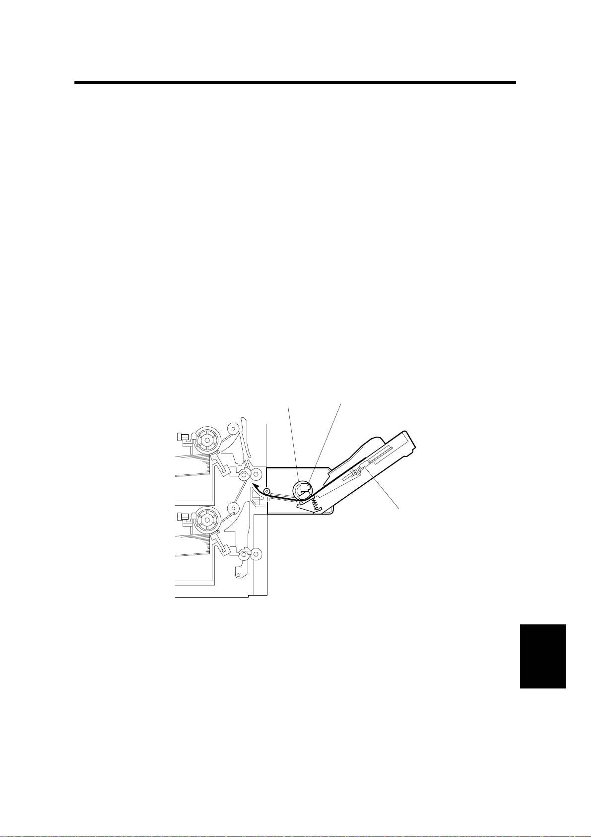
2.1 BASIC OPERATION
[A]
[B]
[C]
B415D503.WMF
The by-pass unit uses a friction pad paper feed mecha ni sm. The transport roller
gear in the main copier/printer drives the gear on the paper feed clutch [B] through
a series of gears.
When paper is placed in the tray, the paper end sensor [C] switches off. When the
Start button is pressed, the paper feed clutch [B] is activated and the paper feed
roller [A] feeds the paper one sheet at a time.
B415-3
Options
Page 5

PAPER SIZE DETECTION 10 August, 2001
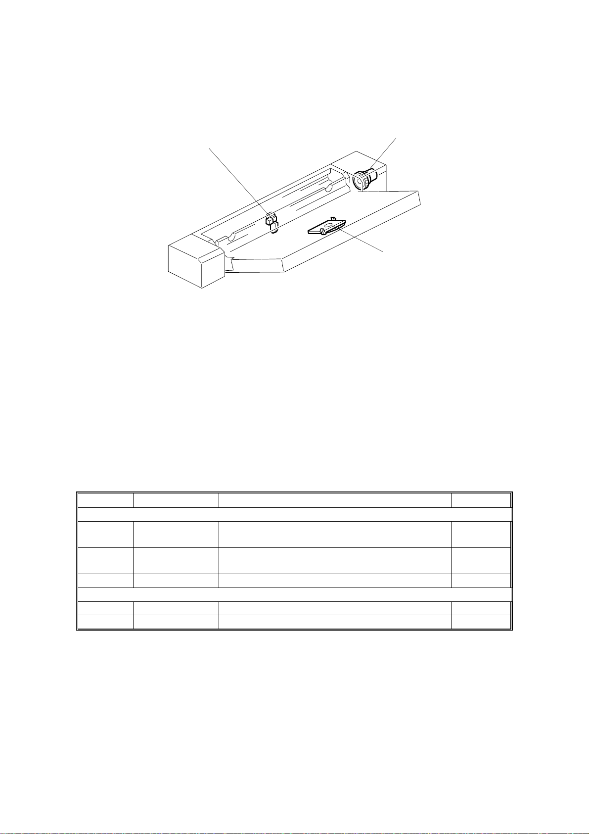
2.2 PAPER SIZE DETECTION
[A]
[B]
B415D504.WMF
The paper size sensor board [B] monitors the paper width. The rear side fence [A]
is connected to the terminal plate. The pattern for each paper width is unique.
Therefore, the copier/printer determines which paper has been placed in the bypass tray by the signal output from the board. However, the copier will not
determine the paper length from the by-pass tray hardware (refer to Original Size
Detection in the manual for the base copier for details on how paper length is
determined).
B415-4
Page 6

10 August, 2001 PAPER FEED ROLLER/FRICTION PAD/PAPER END SENSOR
3 REPLACEMENT AND ADJUSTMENT
3.1 PAPER FEED ROLLER/FRICTION PAD/PAPER END SENSOR
[A]
B415R501.WMF
[C]
[B]
1. Remove the upper cover [A] (2 screws).
2. Remove the paper end sensor bracket [B] (1 screw).
[D]
B415R505.WMF
Options
3. Remove the paper feed roller [C] (snap-fit).
4. If removing the friction pad [D], do so at this time.
B415-5
Page 7

PAPER SIZE SENSOR BOARD 10 August, 2001
3.2 PAPER SIZE SENSOR BOARD
[B]
[A]
[C]
B415R502.WMF
[H]
[G]
[D]
B415R503.WMF
1. Remove the rear cover [A] (2 screws).
2. Remove the by-pass tray [B] (1 connector, 2 release levers [C]).
3. Remove the lever [D] (1 snap ring, 1 pin).
4. While pushing the release lever [E], remove the paper tray [F].
5. Remove the by-pass width sensor [G].
[F]
[E]
NOTE: When installing th e by-pass width sensor [G], move the side fence inward
all the way so that the seal on the side face gear faces the surface with the
seal [H] on the by-pass width sensor.
B415-6
Page 8

10 August, 2001 PAPER FEED CLUTCH
3.3 PAPER FEED CLUTCH
[A]
[C]
1. Remove the rear cover [A] (2 screws).
[D]
[B]
B415R504.WMF
2. Remove the spring.
3. Remove the drive gear and drive gear bracket [B] (1 E-ring, 1 spring).
4. Remove the paper feed clutch bracket [C] (2 screws).
5. Remove the paper feed clutch [D] (1 connector).
Options
B415-7
 Loading...