

Page 1

Fiery XJ BP100 Installation and
Service Guide
for Ricoh NC5006
Ricoh Aficio Color 5106, 5206
Gestetner 2706, 2606, 2606e
Rex Rotary CC8406, CC8606, CC8606E
nashuatec C406, C606, C606e
infotec 7306, 7316, 7316E
Savin SC106, SDC206, SDC206E
Sharp AR-C860
and Lanier 5506 DC color copiers
A guide for service representatives
Page 2

Page 3

Copyright © 1998 Electronics for Imaging, Inc. All rights reserved.
This publication is protected by copyright, and all rights are reserved. No part of it may be reproduced or transmitted in any form or by any means for any purpose without
express prior written consent from Electronics for Imaging, Inc., except as expressly permitted herein. Information in this document is subject to change without notice and
does not represent a commitment on the part of Electronics for Imaging, Inc.
The software described in this publication is furnished under license and may only be used or copied in accordance with the terms of such license.
Trademarks Notice
EFI, the EFI logo, Fiery, the Fiery logo, EFICOLOR and the EFICOLOR logo are trademarks registered in the U.S. Patent and Trademark Office. Fiery XJ, Fiery XJe, Fiery
XJ+, Fiery Driven, the Fiery Driven logo, XJ RipChips, Rip-While-Print, Continuous Print, Command WorkStation, AutoCal, Starr Compression, and Memory Multiplier
are trademarks of Electronics for Imaging, Inc.
Adobe, the Adobe logo, Adobe Illustrator , PostScript, Adobe Photoshop, Adobe Separator, and Adobe P ageMaker are trademar ks of Adobe S ystems Incorporated, register ed in
certain jurisdictions. EPS (Encapsulated PostScript) is a trademark of Altsys Corporation. Apple, the Apple logo, AppleS hare, AppleTalk, EtherTalk, LaserWriter , and Macintosh
are registered trademarks, and MultiFinder is a trademark of Apple Computer, Inc. Microsoft, MS, MS-DOS, and Windows are registered trademarks of M icrosoft in the US
and other countries. QuarkXPress is a registered trademark of Quark, Inc. Times, Helvetica, and Palatino are trademarks of Linotype AG and/or its subsidiaries. ITC Avant
Garde, ITC Bookman, ITC Zapf Chancery, and ITC Zapf Dingbats are registered trademarks of International Typeface Corporation. Ethernet is a registered trademark of
Xerox Corporation. Farallon, PhoneNET PC, and PhoneNET Talk are trademarks of Farallon Computing, Inc. COPS and COPSTalk are trademarks of CoOperative Printing
Solutions, Inc. NetWare and Novell are registered trademarks and Internetwork P acket Ex change (IPX) is a trademark of Novell, Inc. SyQuest is a registered trademark, in the
United States and certain other countries, of SyQuest Technology, Inc. UNIX is a registered trademark of UNIX System Laboratories, a wholly owned subsidiary of Novell,
Inc. PANTONE is a registered trademark of Pantone, Inc. All other terms and product names may be trademarks or registered trademarks of their respective owners, and are
hereby acknowledged.
Legal Notices
APPLE COMPUTER, INC. (“APPLE”) MAKES NO WARRANTIES, EXPRESS OR IMPLIED, INCLUDING WITHOUT LIMITATION THE IMPLIED
WARRANTIES OF MERCHANTABILITY AND FITNESS FOR A PARTICULAR PURPOSE, REGARDING THE APPLE SOFTWARE. APPLE DOES NOT
WARRANT, GUARANTEE, OR MAKE ANY REPRESENTATIONS REGARDING THE USE OR THE RESULTS OF THE USE OF THE APPLE SOFTWARE IN
TERMS OF ITS CORRECTNESS, ACCURACY, RELIABILITY, CURRENTNESS, OR OTHERWISE. THE ENTIRE RISK AS TO THE RESULTS AND
PERFORMANCE OF THE APPLE SOFTWARE IS ASSUMED BY YOU. THE EXCLUSION OF IMPLIED WARRANTIES IS NOT PERMITTED BY SOME
STATES. THE ABOVE EXCLUSION MAY NOT APPLY TO YOU.
IN NO EVENT WILL APPLE, ITS DIRECTORS, OFFICERS, EMPLOYEES OR AGENTS BE LIABLE TO YOU FOR ANY CONSEQUENTIAL, INCIDENTAL
OR INDIRECT DAMAGES (INCLUDING DAMAGES FOR LOSS OF BUSINESS PROFITS, BUSINESS INTERRUPTION, LOSS OF BUSINESS
INFORMATION, AND THE LIKE) ARISING OUT OF THE USE OR INABILITY TO USE THE APPLE SOFTWARE EVEN IF APPLE HAS BEEN ADVISED
OF THE POSSIBILITY OF SUCH DAMAGES. BECAUSE SOME STATES DO NOT ALLOW THE EXCLUSION OR LIMITATION OF LIABILITY FOR
CONSEQUENTIAL OR INCIDENTAL DAMAGES, THE ABOVE LIMITATIONS MAY NOT APPLY TO YOU.
cause whatsoever, and regardless of the form of the action (whether in contract, tort [including negligence], product liability or otherwise), will be limited to $50.
Restricted Rights Legends
For defense agencies: Restricted Rights Legend. Use, reproduction, or disclosur e is subject to restrictions set forth in subparagraph (c)(1)(ii) of the Rights in Technical Data and
Computer Software clause at 252.227.7013.
For civilian agencies: Restricted Rights Legend. Use, reproduction, or disclosur e is subject to restrictions set forth in subparagraph (a) through (d) of the commercial Computer
Software Restricted Rights clause at 52.227-19 and the limitations set forth in Electronics for Imaging, Inc.’s standard commercial agreement for this software. Unpublished
rights reserved under the copyright laws of the United States.
Printed in the United States of America on recycled paper.
Part Number:
45000221
Apple’s liability to you for actual damages from any
Page 4

FCC Information
WARNING: FCC Regulations state that any unauthorized changes or modifications to this equipment not expressly approved by the manufacturer could void the user’s
authority to operate this equipment.
NOTE: This equipment has been tested and found to comply with the limits for a Class A digital device, pursuant to Part 15 of the FCC Rules. These limits are designed to
provide reasonable protection against harmful interference when the equipment is operated in a commercial environment. This equipment generates, and uses, and can radiate
radio frequency energy and, if not installed and used in accordance with the instruction manual, may cause harmful interference to radio communications. Operation of this
equipment in a residential area is likely to cause interference in which case the user will be required to correct the interference at his own expense.
Industry Canada Class A Notice
This digital apparatus does not exceed the Class A limits for radio noise emissions from digital apparatus as set out in the interference-causing equipment standard entitled,
“Digital Apparatus” ICES-003 from Industry Canada.
Avis de Conformation Classe A d l’Industrie Canada
Le présent appareil numérique n’émet pas de bruits radioélectriques dépassant les limites applicables aux appareils numériques de la Classe A prescrites dans la norme sur le
matériel brouilleur, “Appareils Numériques” NMB-003 édictée par l’Industrie Canada.
Certificate by Manufacturer/Importer
This is to certify that the FC07 is shielded against radio interference in accordance with the provisions of VFG 243/1991. The German Postal Services have been advised that
this device is being put on the market and that they have been given the right to inspect the series for compliance with the regulations.
Electronics for Imaging, Inc.
Bescheinigung des Herstellers/Importeurs
Heirmit wird bescheinigt, dass der FC07 im Uebereinstimmung mit den Bestimmungen der VFG 243/1991 Funk-Entstort ist. Der Deutschen Bundespost wurde das
Inverkehrbringen dieses Geraetes angezeigt und die Berechtigung zur Ueberpruefung der Serie auf Einhaltung der Bestimmungen eingeraumt.
Electronics for Imaging, Inc.
RFI Compliance Notice
This equipment has been tested concerning compliance with the relevant RFI protection requirements both individually and on system level (to simulate normal operation
conditions). However, it is possible that these RFI Requirements are not met under certain unfavorable conditions in other installations. It is the user who is responsible for
compliance of his particular installation.
Dieses Geraet wurde einzeln sowohl als auch in einer Anlage, die einen normalen Anwendungsfall nachbildet, auf die Einhaltung der Funk-entstoerbestimmungen geprueft. Es
ist jedoch moeglich, dass die Funk-enstoerbestimmungen unter unguenstigen Umstaenden bei anderen Geraetekombinationen nicht eingehalten wer den. F uer die Einhaltung
der Funk-entstoerbestimmungen seigner gesamten Anlage, in der dieses Geraet betrieben wird, ist der Betreiber verantwortlich.
Compliance with applicable regulations depends on the use of shielded cables. It is the user who is responsible for procuring the appropriate cables.
Einhaltung mit betreffenden Bestimmungen kommt darauf an, dass geschirmte Ausfuhrungen gebraucht werden. Fuer die beschaffung richtiger Ausfuhrungen ist der Betr eiber
verantwortlich.
Software License Agreement
Electronics for Imaging, Inc. grants to you a non-exclusive, non-transferable license to use the software and accompanying documentation (“Softwar e ”) included with the Fiery
XJ Color Server you have purchased, including without limitation the PostScript
®
software provided by Adobe Systems Incorporated.
You may:
a. use the Software solely for your own customary business purposes and solely with Fiery XJ;
b. use the digitally-encoded machine-readable outline and bitmap programs (“Font P rograms ”) pr ovided with Fiery XJ in a special encrypted format (“Coded Font Programs”)
to reproduce and display designs, styles, weights, and versions of letters, numerals, characters and symbols (“Typefaces”) solely for your own customary business purposes on
the screen of the Fiery XJ or Macintosh monitor used with Fiery XJ;
c. use the trademarks used by Electronics for Imaging to identify the Coded Font Programs and Typefaces reproduced therefrom (“Trademarks”); and
d. assign your rights under this Agreement to a transferee of all of your right, title and interest in and to Fiery XJ provided the transferee agr ees to be bound by all of the terms
and conditions of this Agreement.
You may not:
a. make use of the Software, directly or indirectly, to print bitmap images with print resolutions of 600 dots per inch or greater, or to generate fonts or typefaces for use other
than with Fiery XJ;
b. make or have made, or permit to be made, any copies of the Software, Coded Font P r ograms, accompanying documentation or portions thereof, ex cept as necessary for use
with the Fiery XJ unit purchased by you; provided, however, that under no circumstances may you make or have made, or permit to be made, any copies of that certain portion
of the Software which has been included on the Fiery XJ hard disk drive. You may not copy the documentation;
c. attempt to alter, disassemble, decrypt or reverse engineer the Software, Coded Font Programs or accompanying documentation.
d. rent or lease the Software.
Page 5

Proprietary Rights
You ackno wledge that the Software, Coded F ont Programs, T ypefaces, Trademarks and accompanying documentation are proprietary to Electronics for Imaging and its suppliers
and that title and other intellectual property rights therein remain with Electronics for Imaging and its suppliers. Except as stated above, this Agr eement does not grant you any
right to patents, copyrights, trade secrets, trademarks (whether registered or unregistered), or any other rights, franchises or licenses in respect of the Software, Coded Font
Programs, Typefaces, Trademarks or accompanying documentation. You may not adapt or use any trademark or trade name which is likely to be similar to or confusing with
that of Electronics for Imaging or any of its suppliers or take any other action which impairs or reduces the trademark rights of Electronics for Imaging or its suppliers. The
trademarks may only be used to identify printed output produced by the Coded Font Programs. A t the reasonable request of E lectronics for Imaging, you must supply samples
of any Typeface identified with a trademark.
The MacApp software is proprietary to Apple Computer, I nc. and is licensed to Electronics for Imaging, I nc. for distribution only for use in combination with Fiery XJ software
utilities.
Confidentiality
You agree to hold the Software and Coded Font Programs in confidence, disclosing the Software and Coded Font Programs only to authorized users having a need to use the
Software and Coded Font Programs as permitted by this Agreement and to take all reasonable precautions to prevent disclosure to other parties.
Remedies
Unauthorized use, copying or disclosure of the Software, Coded Font Programs, Typefaces, Trademarks or accompanying documentation will r esult in automatic termination
of this license and will make available to Electronics for Imaging other legal remedies.
Limited Warranty And Disclaimer
Electronics for Imaging warrants that, for a period of ninety (90) days from the date of delivery to you, the Software under normal use will perform without significant errors
that make it unusable. Electronics for Imaging’s entire liability and your exclusive remedy under this warranty (which is subject to you returning Fiery XJ to Electronics for
Imaging or an authorized dealer) will be, at Electronics for Imaging’s option, to use reasonable commercial efforts to attempt to correct or work around errors, to replace the
Software with functionally equivalent software, or to refund the purchase price and terminate this Agreement. Some states do not allow limitations on duration of implied
warranty, so the above limitation may not apply to you.
Except for the above express limited warranty, Electronics for Imaging makes and you receive no warranties or conditions on the Products, express, implied, or statutory, and
Electronics for Imaging specifically disclaims any implied warranty or condition of merchantability or fitness for a particular purpose.
For warranty service, please contact your authorized service/support center.
EXCEPT FOR THE ABOVE EXPRESS LIMITED WARRANTY, ELECTRONICS FOR IMAGING MAKES AND YOU RECEIVE NO WARRANTIES OR
CONDITIONS ON THE SOFTWARE OR CODED FONT PROGRAMS, EXPRESS, IMPLIED, STATUTORY, OR IN ANY OTHER PROVISION OF THIS
AGREEMENT OR COMMUNICATION WITH YOU, AND ELECTRONICS FOR IMAGING SPECIFICALLY DISCLAIMS ANY IMPLIED WARRANTY OR
CONDITION OF MERCHANTABILITY OR FITNESS FOR A PARTICULAR PURPOSE. Electronics for Imaging does not warrant that the operation of the software
will be uninterrupted or error free or that the Software will meet your specific requirements.
Page 6

Limitation Of Liability
IN NO EVENT WILL ELECTRONICS FOR IMAGING OR ITS SUPPLIERS BE LIABLE FOR ANY DAMA GES, INCLUDING LOSS OF DATA, LOST PROFITS,
COST OF COVER OR OTHER SPECIAL, INCIDENTAL, CONSEQUENTIAL OR INDIRECT DAMAGES ARISING FROM THE USE OF THE SOFTWARE,
CODED FONT PROGRAMS OR ACCOMPANYING DOCUMENTATION, HOWEVER CA USED AND ON ANY THEORY OF LIABILITY. THIS LIMIT ATION
WILL APPLY EVEN IF ELECTRONICS FOR IMAGING OR ANY AUTHORIZED DEALER HAS BEEN ADVISED OF THE POSSIBILITY OF SUCH DAMAGE.
YOU ACKNOWLEDGE THAT THE PRICE OF FIERY XJ REFLECTS THIS ALLOCATION OF RISK. BECAUSE SOME STATES/JURISDICTIONS DO NOT
ALLOW THE EXCLUSION OR LIMITATION OF LIABILITY FOR CONSEQUENTIAL OR INCIDENTAL DAMAGES, THE ABOVE LIMITATION MAY NOT
APPLY T O YOU.
Export Controls
You agr ee that you will not export or re-export the Softwar e or Coded F ont P rograms in any form without the appropriate United States and foreign government licenses. Y our
failure to comply with this provision is a material breach of this Agreement.
Government Use
Use, duplication or disclosure of the Software by the United States Government is subject to restrictions as set forth in subdivision (c) (1) (ii) of the Rights in Technical Data
and Computer Software clause at DFARS 252.227-7013 or in subparagraphs (c) (1) and (2) of the Commercial Computer Software—Restricted Right Clause at 48 CFR
52.227-19, as applicable.
Third Party Beneficiary
You are hereby notified that Adobe Systems Incorporated, a California corporation located at 1585 Charleston Road, Mountain View, California 94039-7900 (“Adobe”) is a
third-party beneficiary to this Agreement to the extent that this Agreement contains provisions which relate to your use of the Fonts, the Coded Font Programs, the Typefaces
and the Trademarks licensed hereby. Such provisions are made expressly for the benefit of Adobe and are enforceable by Adobe in addition to Electronics for Imaging.
General
This Agreement will be governed by the laws of the State of California.
This Agreement is the entire agreement held between us and supersedes any other communications or advertising with respect to the Software, Coded Font Programs and
accompanying documentation.
If any provision of this Agreement is held invalid, the remainder of this Agreement shall continue in full force and effect.
If you have any questions, please contact in writing:
Electronics for Imaging, Inc.
2855 Campus Drive
San Mateo, California 94403
Page 7

Installation and Service Guide
Contents 1
Preface
About this guide xi
About the illustrations in this guide xii
Terminology and conventions xii
Precautions xiii
Tools you will need xv
Chapter 1: Introduction
How the Fiery XJ BP100 operates 1-2
Fiery XJ BP100 print options 1-3
Fiery XJ BP100 user software 1-4
Fiery WebT ools 1-4
Chapter 2: Preparing for Fiery XJ BP100 Installation
Overview of the installation procedure 2-1
Preparation for Fiery XJ BP100 installation 2-3
Customer site checklist 2-3
Setting customer expectations 2-6
Verifying site readiness 2-7
Unpacking the Fiery XJ BP100 2-8
Using the Fiery XJ BP100 Control Panel 2-12
Fiery XJ BP100 Control Panel screens 2-13
Chapter 3: Connecting the Fiery XJ BP100
Preliminary checkout of the Fiery XJ BP100 3-1
Connecting the Fiery XJ BP100 to the copier 3-5
Verifying the connection 3-6
Installing additional options 3-8
Connecting the Fiery XJ BP100 to the network 3-8
Ethernet network connections 3-8
Connecting parallel port devices
to the Fiery XJ BP100 3-11
Connecting a CD-ROM drive to the Fiery XJ BP100 3-12
Shutting down and restarting the Fiery XJ BP100 3-13
vii
Page 8

Installation and Service Guide
Chapter 4: Setting Up the Fiery XJ BP100
Using Setup 4-1
When to perform Fiery XJ BP100 Setup 4-2
Accessing Setup options 4-3
Running Setup 4-5
Types of setup screens 4-5
Chapter 5: Service Procedures
Servicing the Fiery XJ BP100 5-1
Software service 5-1
Accessing Fiery XJ BP100’s internal components 5-3
To shut down the Fiery XJ BP100 5-3
To open the Fiery XJ BP100 chassis 5-3
Checking Fiery XJ BP100’s internal connections 5-7
To check board and cable connections 5-7
To check motherboard SIMM connections 5-10
Restoring Fiery XJ BP100 functionality after service 5-11
Removing and replacing circuit boards 5-13
Video interface board 5-13
STARR daughter card 5-14
User interface board 5-17
Motherboard 5-20
Removing the Fiery XJ BP100 motherboard 5-20
Replacing the motherboard 5-27
Replacing parts on the motherboard 5-31
Motherboard switches 5-36
Intake fan 5-37
Power switch 5-38
Power supply 5-39
Checking voltages 5-40
Removing and replacing the power supply 5-42
Hard disk drive 5-43
The Fiery XJ BP100 Software Service Kit 5-46
Installing Fiery XJ BP100 system software 5-47
viii
Page 9

Installation and Service GuideInstallation and Service Guide
Chapter 6: Troubleshooting Procedures
The troubleshooting process 6-1
Where problems occur 6-3
Before you go to the customer site 6-4
Preliminary on-site checkout 6-6
Checking the interface cables 6-6
Checking the internal components 6-7
Checking the Fiery XJ BP100 as a stand-alone unit 6-9
Isolating the Fiery XJ BP100 6-9
Errors during the Start-up diagnostics 6-9
General Fiery XJ BP100 system error conditions 6-12
Fiery XJ BP100’s diagnostic sets 6-16
Viewing the diagnostic report 6-29
Video interface board diagnostics 6-31
Checking the entire Fiery XJ BP100 system 6-33
Checking the copier interface 6-33
Checking network connections 6-34
Printing to the Fiery XJ BP100 6-35
Appendix A: Specifications
Hardware features A-1
Networking and connectivity A-1
Fiery XJ BP100 user software A-1
Safety and emissions compliance A-2
Appendix B: Assembling the Fiery XJ BP100 Furniture
Index
ix
Page 10

Page 11

Installation and Service Guide
Preface
The Installation and Service Guide is intended for certified
Fiery XJ BP100
servicing a Fiery XJ BP100 Color Server
installation and service certification, you should not attempt to
install or service a Fiery XJ BP100 Color Server. Electronics for
Imaging, Inc. does not warrant the performance of Color Servers
installed or serviced by non-certified personnel.
About this guide
This guide is divided into the following sections:
• “Preface ” gives general information about this guide and general
information that you should know before you attempt to install
a Fiery XJ BP100.
• Chapter 1, “Introduction”, provides general information about
the Fiery XJ BP100.
™
and copier service technicians installing or
™
. If you have not received
• Chapter 2, “Preparing for Fiery XJ BP100 Installation”,
describes the steps you need to take before you install the unit.
This chapter also includes an overview of the Control Panel.
• Chapter 3, “Connecting the Fiery XJ BP100”, tells you how to
connect the Fiery XJ BP100 to the copier and the network and
verify that the system is working correctly.
• Chapter 4, “Setting Up the Fiery XJ BP100”, describes how to
configure the Setup options.
• Chapter 5, “Service Procedures”, describes removal and
replacement procedures for Fiery XJ BP100 components.
• Chapter 6, “Troubleshooting Procedures”, identifies the source
of common problems and suggests ways of correcting them.
Fiery XJ BP100 customers should not use the technical service
documentation. Please don’t leave your copy of the Installation and
Service Guide behind after you make a service call.
xi
Page 12

Installation and Service Guide
Preface
About the illustrations in this guide
The illustrations in this guide reflect the current shipping version of
the Fiery XJ BP100 at the time of publication. Components shown
in these illustrations are subject to change. To receive information
about any Fiery XJ BP100 components that do not match
illustrations in this guide, contact your authorized service/support
center. Technical notes will be provided following major
Fiery XJ BP100 hardware changes.
Terminology and conventions
The term network administrator refers to the person responsible for
maintaining the network at the customer site.
The term
Control Panel
the Fiery XJ BP100 that includes the green/red activity light, the
display window (LCD—liquid crystal display), and the buttons to
the right of and below the display window.
™
is used to describe the area on the front of
The term PC-compatible refers to any IBM PC-compatible
computer capable of running Windows 95.
The term PC-based server refers to any device that may be connected
to the Fiery XJ BP100 for parallel printing.
When this guide refers to other Fiery XJ BP100 manuals, such as
the
Administrator Guide,
the title is displayed in italics.
The arrow highlights important notes and additional information.
The caution icon indicates a need for special care and safety when
!
handling the equipment.
Fiery XJ BP100 Control Panel screen messages and commands
referred to in the text of this guide appear in the
Univers
typeface.
xii
Page 13

PrefaceInstallation and Service Guide
Precautions
Always observe the following general precautions when installing
and servicing the Fiery XJ BP100:
1. Report any shipping damage.
If there is any evidence of shipping or handling damage to the
Fiery XJ BP100 packing boxes or their contents, save the
damaged boxes and parts, call the shipper immediately to file a
claim, and notify your authorized service/support center.
2. Never alter an existing network without permission.
The Fiery XJ BP100 will probably be connected to an existing
Local Area Network (LAN) based on Ethernet
network is the link between the customer’s computer, existing
laser printers, and other prepress equipment. Never disturb the
LAN by breaking or making a network connection, altering
termination, installing or removing networking hardware or
software, or shutting down networked devices without the
knowledge and express permission of the system or network
administrator or the shop supervisor.
®
hardware. The
3. Never enter an IP address in Fiery XJ BP100 Network Setup.
Only the network administrator should enter an IP address on a
network device. Assigning a Fiery XJ BP100 an incorrect IP
address can cause unpredictable errors on any or all devices
connected to the network.
4. Always disconnect power before opening the Fiery XJ BP100
chassis.
Although Fiery XJ BP100 circuitry operates on 5V DC and
12V DC, 115V AC is present when the chassis cover is
removed. Before you service the Fiery XJ BP100, shut it down
completely (switch the Fiery XJ BP100 off and unplug the AC
power cord from the rear of the Fiery XJ BP100).
5. Handle the Fiery XJ BP100 Control Panel display window with
care.
The Fiery XJ BP100 display window is made of glass. If the
glass breaks and the liquid crystal inside leaks out, avoid contact
with it. If you do come in contact with the liquid crystal, wash it
off with soap and water immediately.
6. Avoid pressing the surface of the display window.
Applying pressure to the display window will cause it to change
color.
xiii
Page 14

Installation and Service Guide
Preface
7. Use a soft cloth moistened with isopropyl or ethyl alcohol to clean
the surface of the Fiery XJ BP100 display window.
Other solvents, such as water, may damage the polarizer on the
display window.
8. Follow standard ESD (electrostatic discharge) precautions while
working on the internal components of the Fiery XJ BP100.
Static is always a concern when servicing electronic devices. It is
highly unlikely that the area around the copier and the
Fiery XJ BP100 is static-free. Carpeting, leather-soled shoes,
synthetic clothing fibers, silks, and plastics may generate a static
charge of more than 10,000 volts. Static discharge is capable of
destroying the circuits etched in silicon microchips, or
dramatically shortening their life span. By observing standard
precautions, you may avoid extra service calls and save the cost
of a new board.
When possible, work on a ground-connected antistatic mat.
Wear an antistatic wristband, grounded at the same place as the
antistatic mat. If that is not possible:
• Attach a grounding strap to your wrist. Attach the other end
to a good ground.
• When you unpack the Fiery XJ BP100 from the carton for
the first time, touch a metal area of the copier to discharge
the static on your body.
• Before you remove the F iery XJ BP100 cover and before you
handle internal components, touch a metal part of the
Fiery XJ BP100 chassis.
• Leave new electronic components inside their antistatic bags
until you are ready to install them. When you remove
components from an antistatic bag, place them on a
grounded antistatic surface, component-side up.
• When you remove an electronic component, place it into an
antistatic bag immediately. Do not walk across a carpet or
vinyl floor while carrying an unprotected board.
9. Handle printed circuit boards by their edges only, but avoid
touching the contacts on the edge of the board.
10. Never set a cup of coffee—or any liquid—on or near the
Fiery XJ BP100 or the copier.
xiv
Page 15

PrefaceInstallation and Service Guide
Tools you will need
To install or service the Fiery XJ BP100, you should bring the
following tools and parts:
• ESD wrist grounding strap
• Wire cutters
• #0 and #1 Phillips head screwdrivers (non-magnetic)
• Small flat-blade screwdriver (non-magnetic)
• Small needlenosed pliers
• 5/16" wrench
• Flashlight
You should also bring this guide and the latest Fiery XJ BP100
technical notes for the Fiery XJ BP100 and the customer network
type.
xv
Page 16

Page 17
Installation and Service Guide
Chapter 1: Introduction 1
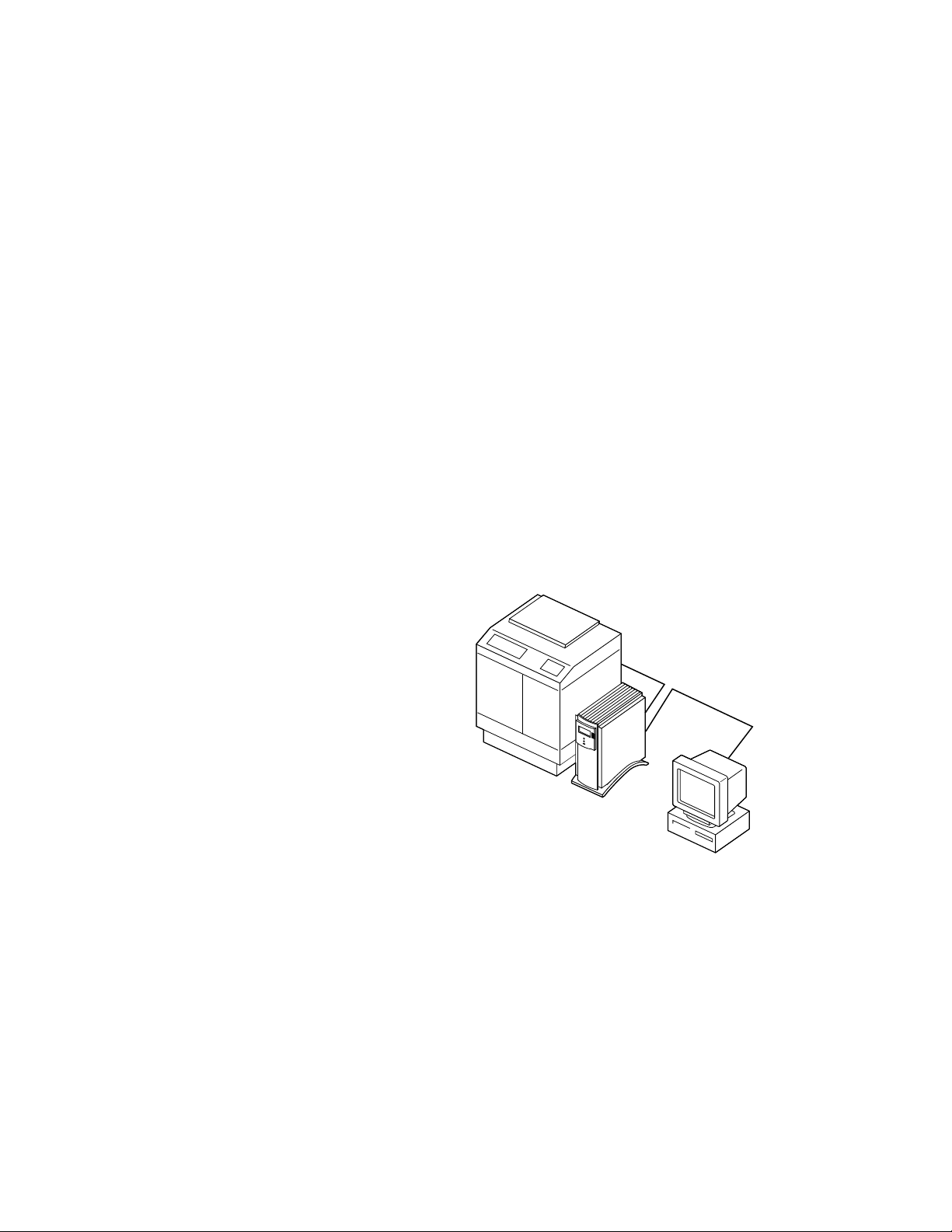
The Fiery XJ BP100 Color Server adds computer connectivity and
highly efficient PostScript color printing capacity to color copiers.
The Fiery XJ BP100, as an integral part of a color printing system,
enables users of Macintosh computers, PC-compatibles, and UNIX
workstations to:
• Send images over AppleTalk, TCP/IP, Novell networks, and
through a parallel port to print on a Fiery XJ BP100-supported
copier.
• Spool print jobs and select a printing priority for each job. U sers
can also control spooled print jobs sent to the Fiery XJ BP100
with remote utility software running on networked Macintosh
and PC-compatible computers.
• Print PostScript and EPS files, in color and grayscale.
• Use 136 resident PostScript 3 fonts. The customer can
download additional fonts as needed.
Copier/Printer
Fiery XJ BP100
Networked
computer or
workstation
Figure 1-1 Fiery XJ BP100 color printing system
The Fiery XJ BP100 is one of several color imaging products
engineered and manufactured by Electronics for Imaging, Inc.
1-1
Page 18

Installation and Service Guide
1: Introduction
How the Fiery XJ BP100 operates
The Fiery XJ BP100 enables the customer to use a color copier as a
printer. Users can print to the Fiery XJ BP100 from networked
Apple Macintosh computers, from networked IBM PC or
compatible computers running Microsoft
networked UNIX workstations running TCP/IP. In addition, the
Fiery XJ BP100 parallel port can be used to print directly from a
PC.
The Fiery XJ BP100’s custom-designed boards and operating
software are responsible for the Fiery XJ BP100’s efficient image
processing and printing controls. The main functions of
Fiery XJ BP100 components and software are described below.
The Fiery XJ BP100 uses two specialized circuit boards to process
image data for printing color images: the motherboard and the
video interface board.
®
Windows
™
, and from
The motherboard includes a MIPS 4700 RISC (Reduced
Instruction Set Computer) CPU with a built-in floating point
accelerator that runs Adobe’s PostScript Interpreter. The PostScript
Interpreter interprets the PostScript page description file and
ST ARR technology compresses the image pattern into memory . The
RipChips
™
on the motherboard control data management and
other system functions, freeing up the CPU for efficient image data
processing.
High-speed SIMMs (single in-line memory modules) on the
motherboard hold the color image data during printing. The
Fiery XJ BP100 is configured for 64MB of memory.
The PostScript Interpreter outputs raster data through the image
frame buffer memory to the Fiery XJ BP100 STARR daughter card
installed on the video interface board. The STARR daughter card
decompresses the image data and sends it to the copier interface
port through the video interface board and the copier interface
cable. The raster data is supplied to the laser in the copier at full
copier rates in order to charge the drum and render the final image
on paper.
1-2
Page 19
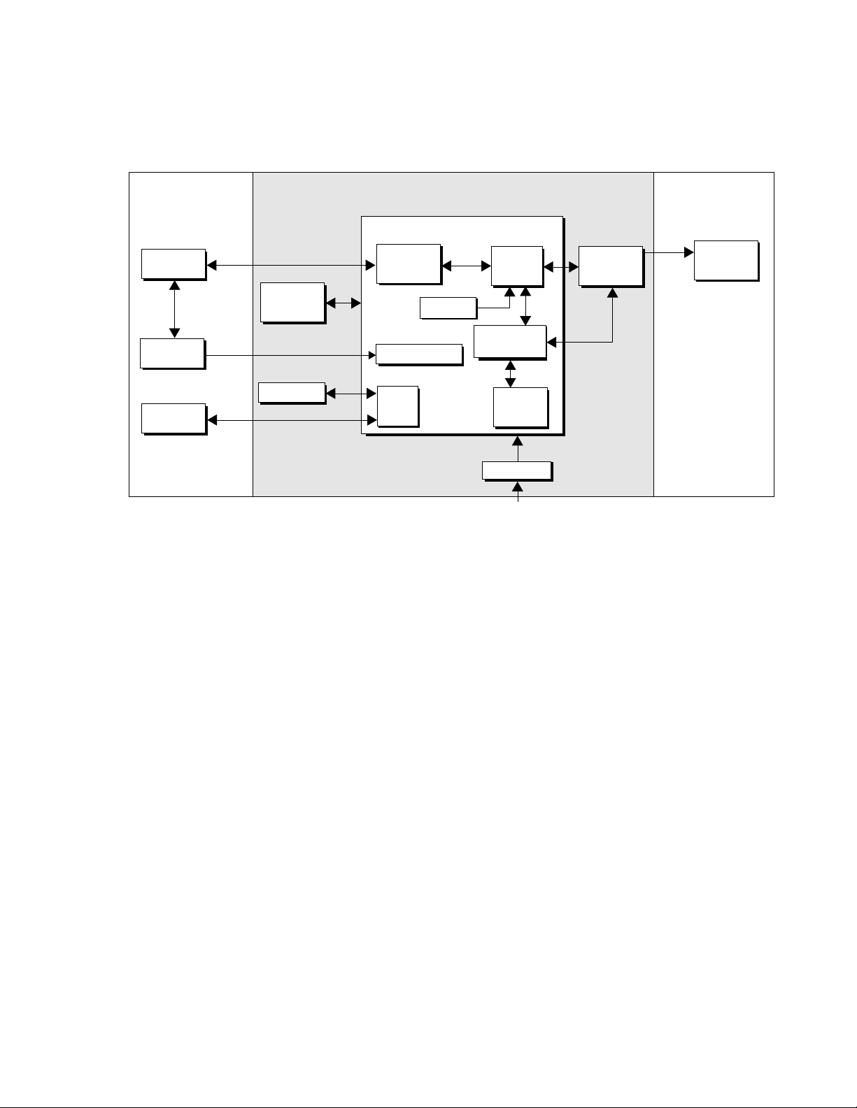
1: IntroductionInstallation and Service Guide
Network CopierFiery XJ BP100
Motherboard
Networked
computers
Server
User interface
board
Network
interface
chips
EPROM &
EEPROM
Parallel interface
CPU
Fiery XJ BP100
RipChips
Video
interface
board
Print
Copier
External SCSI
device(s)
Hard drive
SCSI
interface
Memory
SIMMs
& CPSI
+5/±12VDC
Power supply
AC power
Figure 1-2 Fiery XJ BP100 functional diagram
Fiery XJ BP100 print options
The Fiery XJ BP100’s efficient capabilities allow customers to use a
variety of applications to create and print pages of text and/or
images. The Fiery XJ BP100 operates over a network or by printing
directly to the parallel port. Since the Fiery XJ BP100 has the ability
to print an image while processing the next image (RIP-While-
™
Print
), it is capable of printing documents at full copier speeds.
Printing over a network allows Fiery XJ BP100 users to print
documents directly from applications in which they were created. In
addition, Fiery XJ BP100 offers an efficient way to print files that
have been saved in PostScript or EPS (Encapsulated PostScript)
format. These files can be downloaded directly to the
Fiery XJ BP100 using the Fiery XJ Downloader, one of the remote
utilities provided with Fiery XJ BP100.
With the parallel port option, customers can print documents
directly from applications running on a PC-compatible computer or
a server that is connected to the Fiery XJ BP100’s parallel port.
PostScript files can also be printed to the parallel port from the
DOS prompt or the Windows File Manager.
1-3
Page 20

Installation and Service Guide
1: Introduction
Fiery XJ BP100 user software
Fiery XJ BP100 user software is provided on the User Software CD.
The network administrator or the user at the customer site is
responsible for installing software onto computers that will use the
Fiery XJ BP100 over a network. Some user software can also be
installed from Fiery WebTools Installer (see the
information on Fiery WebTools).
The Fiery XJ BP100 User Software CD (for PC-compatible or
Macintosh computers) contains the following software:
• The Fiery XJ Downloader™ is a Fiery XJ BP100 utility that
allows the customer to download PostScript or EPS files to the
Fiery XJ BP100 without opening the file or the application that
created the file. The Fiery XJ Downloader also allows the
customer to manage the printer fonts on the Fiery XJ BP100.
User Guide
for more
• The Fiery XJ Spooler™ is a utility that allows a user to control
Fiery XJ BP100 print jobs from a networked PC or Macintosh
computer. It allows the user to view the order and priority of a
job, delete jobs, and move jobs between queues.
• A set of Adobe Macintosh screen fonts that correspond to the
PostScript printer fonts resident on the Fiery XJ BP100.
• Printer description files that allow remote users to access special
features when printing.
• Printer drivers for Macintosh and Windows. They allow
applications to communicate with the Fiery XJ BP100 and use
all the printing features of the Fiery XJ BP100.
• Color Reference pages to view the range of colors available on
the Fiery XJ BP100.
Fiery WebTools
The Fiery XJ BP100 can support Internet or intranet access with
Fiery WebTools. WebTools include Status, Installer, and
WebSpooler. For more information about WebTools, see the
Administrator Guide and the User Guide .
1-4
Page 21

Installation and Service Guide
Chapter 2: Preparing for Fiery XJ BP100 Installation 2
This chapter includes the following information:
• Summary of the installation procedure
• Preparing a customer site for Fiery XJ BP100 installation
• Unpacking the Fiery XJ BP100
Overview of the installation procedure
Familiarize yourself with Chapters 2 through 4 of this guide before
you attempt an installation. The installation sequence described in
this chapter is designed to make your job as easy as possible.
Installation problems are easier to avoid and diagnose if you proceed
from the component to the system level and verify functionality at
each stage. Figure 2-1 on page 2-2 outlines the recommended
installation procedure for connecting the Fiery XJ BP100 to the
copier.
Because the Fiery XJ BP100 is a component of the customer’s
computer network, make sure that you coordinate your scheduled
installation with the network administrator at the customer site.
Refer the network administrator to the
network setup information.
For sites that print to the Fiery XJ BP100 through a parallel
(Centronics) port, you will need the parallel (Centronics) printer
cable shipped with the Fiery XJ BP100. If you use your own parallel
printer cable, it must have a male 36-pin D-shell connector on one
end and a 25-pin male D-sub, shielded connector at the other end,
and cannot be more than six feet long. Because of the cable
arrangement necessary to connect the Fiery XJ BP100 to a
PC-based server, make sure the customer has enough space near the
copier for both the Fiery XJ BP100 and the server.
Administrator Guide
for
2-1
Page 22
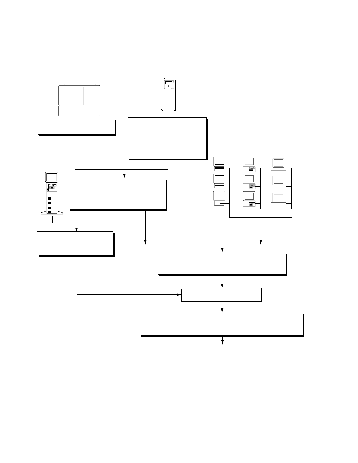
Installation and Service Guide
Copier/Printer
Print copier test page, page 2-7
PC- based
server
Connect copier interface cable, page 3-5
Print a Fiery XJ BP100 test page, page 3-7
Install options, page 3-8
2: Preparing for Fiery XJ BP100 Installation
Fiery XJ BP100
Verify site, page 2-7
Unpack, page 2-8
Checkout Fiery XJ BP100, page 3-1
Perform printer setup (see the
Administrator Guide
)
Macintosh
computers
PC-compatible
computers
UNIX
workstations
Network administrator connects
Fiery XJ BP100 to parallel port of
PC-based server, page 3-11
Network administrator connects the Fiery XJ BP100 to the
network and verifies the connection (see page 3-8 and the
Administrator Guide
)
Configure setup options, page 4-1
Network administrator loads Fiery XJ BP100 remote utilities and printer
description files on networked computers (see
Administrator Guide
)
Full Fiery XJ BP100 functionality
Getting Started
and the
Figure 2-1 Recommended installation steps and references
2-2
Page 23

2: Preparing for Fiery XJ BP100 InstallationInstallation and Service Guide
Preparation for Fiery XJ BP100 installation
Before you visit a customer site to install the Fiery XJ BP100, call
ahead to verify site conditions and inform the customer of
installation requirements.
Note that the software versions listed in the checklist below reflect
compatible versions at the time of publication. If you are using a
later version of the software, contact your authorized
service/support center to determine Fiery XJ BP100 system
compatibility.
Customer site checklist
1. Copier model
What copier model is installed?
Are the copier interface card and connector installed in the
copier?
Is there space near the copier for the Fiery XJ BP100?
2. Power
Is there a dedicated grounded electrical outlet near the copier for
the Fiery XJ BP100?
3. Computers
If Macintosh computers on the network will be supported by
the Fiery XJ BP100:
• Do networked Macintosh computers have an Ethernet card
or Ethernet built-in?
• Are networked Macintosh computers running a compatible
version of the system software?
• Do networked Macintosh computers use a compatible
version of Adobe PSPrinter driver?
If PC-compatibles on the network will be supported by the
Fiery XJ BP100:
• Do networked PC-compatible computers use a compatible
version of the Adobe P ostScript Printer D river for Windows?
2-3
Page 24

Installation and Service Guide
2: Preparing for Fiery XJ BP100 Installation
Windows 95
• Do PC-compatibles that will be printing to the
Fiery XJ BP100 have Microsoft Windows 95 software with
the SPX/IPX networking protocol set up?
Windows NT
• Do PC-compatibles that will be printing to the
Fiery XJ BP100 have Microsoft Windows NT with TCP/IP
networking protocol set up?
4. Network
Will a new network node for the Fiery XJ BP100 be ready on
the installation date?
What kind of network will the Fiery XJ BP100 be installed on?
Is a compatible version of the network software installed?
• AppleTalk (for Macintosh or Windows 3.x)
• SPX/IPX (for Windows 3.x or Windows 95)
• TCP/IP (for Windows NT)
What is the network cable and connection type?
• Thinnet
• Thicknet
• Twisted pair (10Base-T)
Will network hardware be ready for the Fiery XJ BP100
installation?
• Thinnet and thicknet: Will a network cable be ready?
2-4
Page 25

2: Preparing for Fiery XJ BP100 InstallationInstallation and Service Guide
5. TCP/IP networks
Does the UNIX network support RFC1179 (Berkeley lpr
Protocol)?
Does the network administrator already have a valid IP address,
subnet mask, and a gateway address to assign in Setup?
Inform the network administrator that it may be necessary to:
• Edit the
/etc/hosts
file to include the Fiery XJ BP100 as a
network device.
• Create a spool directory in the
/usr/spool
• Add Fiery XJ BP100 information to the /
Specific instructions and a sample
printcap
directory.
etc/printcap
entry for the
file.
Fiery XJ BP100 are provided in the Administrator Guide .
6. Novell networks
Will the network administrator be available during installation
to configure the system for the Fiery XJ BP100 and verify the
connection?
Is the Novell file server running Novell NetWare software
version 3.11, 3.12, or 4.x in emulation mode that supports
Frame Ethernet 802.3 or 802.2?
7. Parallel port connections to the Fiery XJ BP100
Is a tested parallel (Centronics) printer cable available (cable is
provided with the Fiery XJ BP100)?
Is there room for both the Fiery XJ BP100 and the PC-based
server that will be connected to the Fiery XJ BP100?
8. System contact person
Will the person responsible for the computers and the network
be available at the time set for installation? Get a name as a
contact.
2-5
Page 26

Installation and Service Guide
2: Preparing for Fiery XJ BP100 Installation
Setting customer expectations
If the site is ready, installation takes about one hour. The customer
should be informed of the following:
• The network may be unavailable for up to one hour.
• The copier may be unavailable for up to one hour.
• The network administrator needs to be available during the
installation for network connectivity.
Equipment downtime and impact on the network can be
minimized if the network administrator installs a network
connector for the Fiery XJ BP100 and confirms network
functionality with the connector in place before the date
scheduled for the Fiery XJ BP100 installation.
• The network administrator should have a networked computer
available during the installation. The appropriate software
should already be installed. Documentation for the networked
computer and the network operating software should be
available.
• The network administrator should install the remote utility
software shipped with the Fiery XJ BP100 (a package of user
documentation is also included) onto networked Macintosh and
PC-compatible computers that will print to the
Fiery XJ BP100. (See “Fiery XJ BP100 user software” on
page 1-4.)
Note: This guide covers Fiery XJ BP100 hardware installation and
service. It provides general information on connecting the
Fiery XJ BP100 to the customer’s network. H owev er , networ k setup
and configuration information goes beyond the scope of this guide.
For network setup and configuration information, the network
administrator should refer to the Administrator Guide .
2-6
Page 27

2: Preparing for Fiery XJ BP100 InstallationInstallation and Service Guide
Verifying site readiness
Before unloading and installing the Fiery XJ BP100, verify that the
customer site is prepared.
!
1. Check the electrical source.
Locate the grounded electrical outlet that will supply power to
the Fiery XJ BP100. You should not run the Fiery XJ BP100
and the copier on the same circuit. Use surge suppressors for
both the Fiery XJ BP100 and the copier.
• Do not use a 3-prong adapter in a 2-hole ungrounded outlet.
• Do not use an extension cord.
• Do not plug the Fiery XJ BP100 into a circuit with heating
or refrigeration equipment (including water coolers).
• Do not plug the Fiery XJ BP100 into a switchable wall
outlet. This can result in the Fiery XJ BP100 being turned
off accidentally.
2. Check the intended location for the Fiery XJ BP100.
Make sure that there is space for the Fiery XJ BP100. You may
need to move the copier out from the wall for easier access to the
copier interface port.
3. Test copier functionality before installing the Fiery XJ BP100.
Copy the copier color test page before you install the
Fiery XJ BP100.
If the copied image indicates that the copier needs adjustment,
inform the customer. After getting approval, complete the
copier service needed. Make a new copy of the test page and
continue with the next procedure.
4. Check the network.
Verify that the network is functioning before you attach the
Fiery XJ BP100.
• Ask the network administrator to print a document on a
shared printer over the network.
• Ask the network administrator to verify the computer and
network requirements as specified in “Customer site
checklist” on page 2-3.
2-7
Page 28

Installation and Service Guide
2: Preparing for Fiery XJ BP100 Installation
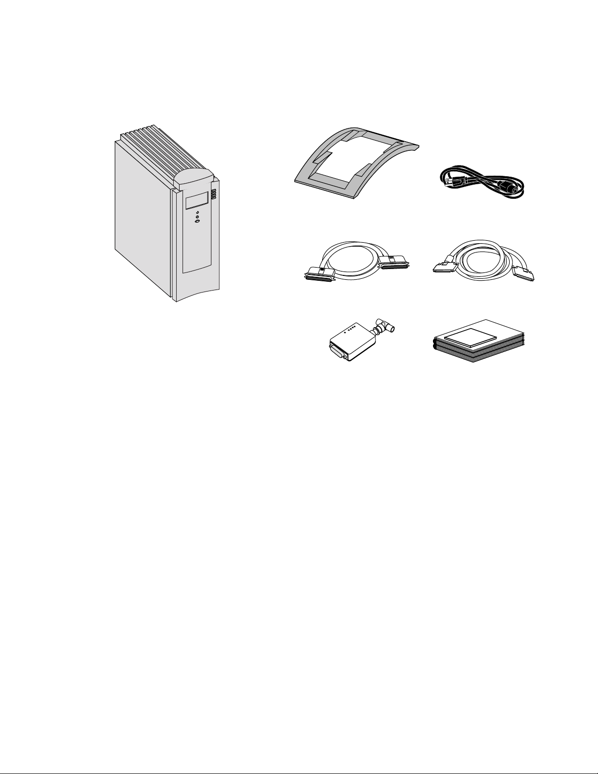
Unpacking the Fiery XJ BP100
The Fiery XJ BP100 is assembled and shipped from the factory in a
box that includes all cables and documentation, as shown in
Figure 2-2 on page 2-9. In addition to the Fiery XJ BP100 Color
Server, a box containing the Fiery XJ BP100 furniture may be
shipped from the factory.
To unpack the Fiery XJ BP100
Save the original boxes and packing materials. If you need to
transport the Fiery XJ BP100 at a later date, the original box and
packing material will ensure safe shipment.
1. If Fiery XJ BP100 furniture is included with your shipment, open the
2. Open the Fiery XJ BP100 Color Server box and remove the packing
box and if necessary, assemble the furniture (see the instructions
that came in the box with the furniture or Appendix B).
material.
3. Remove the contents from the top tray. Inspect the contents for
visible damage. The contents of the tray should include the
following items:
• Bags containing the copier interface cable (16' long, gray,
with 100-pin D-connectors), a Fiery XJ BP100 AC power
cable, and a parallel (Centronics) port cable.
• Fiery XJ BP100 stand (includes 2 screws for attaching it to
the Fiery XJ BP100)
• AUI to BNC Ethernet Transceiver
• SCSI terminator
• Media package (includes user documentation, and User
Software CD)
Note that a service kit containing the System Software CD is
ordered separately.
2-8
Page 29
2: Preparing for Fiery XJ BP100 InstallationInstallation and Service Guide
Fiery XJ BP100
Note: This illustrations does not
include the SCSI terminator.
Fiery XJ BP100 stand
Parallel (Centronics) port cable Copier interface cable
Ethernet transceiver Media package
Power cable (US version)
Figure 2-2 Contents of Fiery XJ BP100 shipping box
2-9
Page 30

Installation and Service Guide
2: Preparing for Fiery XJ BP100 Installation
4. Give the media package to the customer or the network
administrator.
Let the customer or network administrator know that in order
to take full advantage of the Fiery XJ BP100, the user software
must be installed on computers that will print to the
Fiery XJ BP100.
5. Set aside the remaining Fiery XJ BP100 cables, Ethernet
transceiver, SCSI terminator, and the Fiery XJ BP100 stand.
6. Remove the tray and any packing materials. Set the tray and the
packing material aside in case you need to reship the unit.
7. Carefully lift the Fiery XJ BP100 out of the box.
If you notice shipping damage to any Fiery XJ BP100 component,
be sure to save the shipping container in case the carrier needs to see
it. Call the carrier immediately to report the damage and file a
claim, then call your authorized service/support center. Be ready to
furnish the serial number, printed on the back of the
Fiery XJ BP100 chassis.
To attach the stand to the Fiery XJ BP100
If you place the Fiery XJ BP100 in the furniture brackets (see
Appendix B), you do not need to attach the Fiery XJ BP100 stand.
1. Set the Fiery XJ BP100 on a flat surface, with the front of the
chassis facing up (see Figure 2-3 on page 2-11).
2. Place the stand over the bottom of the Fiery XJ BP100 so the holes
in the stand line up with the holes on the bottom of the chassis.
2-10
Page 31

2: Preparing for Fiery XJ BP100 InstallationInstallation and Service Guide
3. Attach the stand using the two screws included with the shipment.
Figure 2-3 Attaching the Fiery XJ BP100 stand
You will connect the Fiery XJ BP100 to the copier and the network
after you verify that the Fiery XJ BP100 powers up properly. The
following section describes the buttons on the front of the
Fiery XJ BP100 and the different functions available from the
Control Panel. You will select functions from the Control Panel
when you turn on the Fiery XJ BP100.
2-11
Page 32

Installation and Service Guide
2: Preparing for Fiery XJ BP100 Installation
Using the Fiery XJ BP100 Control Panel
This section describes the Control Panel on the front of the
Fiery XJ BP100. Once you install the Fiery XJ BP100 and verify
that it powers up correctly (described in “Connecting the
Fiery XJ BP100” on page 3-1), you will use the Control Panel to
access and monitor different functions of the Fiery XJ BP100.
The current status of the Fiery XJ BP100 and Setup information is
displayed in the Fiery XJ BP100 display window. Fiery XJ BP100
activity can be monitored in the display window, and functions of
the Fiery XJ BP100 can be controlled locally using the buttons on
the Control Panel (such as printing a test page and installing or
updating system software).
Activity light
Display window
Line selection
buttons
Up arrow
Down arrow
Menu button
Figure 2-4 The Fiery XJ BP100 Control Panel
The physical controls and status indicators on the Control Panel,
from the top down, are:
• The activity light at the top of the Control Panel
• The display window
2-12
• The four line selection buttons to the right of the display
window
• The up and down arrow buttons for scrolling and editing
• The menu button (oval button at the bottom)
Page 33

2: Preparing for Fiery XJ BP100 InstallationInstallation and Service Guide
Fiery XJ BP100 Control Panel screens
When the Fiery XJ BP100 is in Print mode, pressing the menu
button cycles among four screens: three status screens (Info, RIP,
and Print) and the Functions menu (see Figure 2-5). When the
Fiery XJ BP100 is idle, pressing the menu button cycles between the
Info screen and the Functions menu. The Fiery XJ BP100 screens
display the following information:
•
Info
status screen—Displays the current system software version,
the amount of disk space available on the hard disk drive, the
printer name on the network, and the current Fiery XJ BP100
status (Printing, Processing, Error, or Idle).
•
status screen—Displays information about the job currently
RIP
being processed and allows you to cancel the job.
•
Print
status screen—Displays information about the job
currently being printed and allows you to cancel the print job.
•
Functions
menu—Gives you access to administrative functions
not normally performed from a remote workstation (see
“Functions menu” on page 2-15 for information on the
available functions).
Cancel Job >
Cancel Job >
Job name
doc.eps
User name
Jack D.
Processed:
Busy #####K
RIP
RIP
RIP status screen
Server Name
Idle
1744MB X.0
Info
Info status screen
Figure 2-5 Fiery XJ BP100 Control Panel screens
bytes
Print status screen
Print Pages
Suspend Printing
Resume Printing
Run Diagnostics
Functions
Functions menu
Cancel Job >
Jane D.
Copies: 1/100
Print
2-13
Page 34

Installation and Service Guide
2: Preparing for Fiery XJ BP100 Installation
Fiery XJ BP100 Control Panel screen icons
The row of icons at the bottom of the Control Panel window
display information about the current status of the Fiery XJ BP100.
The highlighted icon corresponds to the screen that is currently
displayed. Pressing the menu button allows you to move between
the available screens (available screens are displayed in the row of
icons at the bottom of the Control Panel). See Table 2-1 for a
description of the different icons.
Table 2-1 Fiery XJ BP100 Control Panel screen icon descriptions
Fiery XJ BP100
screen icon
Description
Alert
The
icon is highlighted when the Control Panel
shows the Error screen.
The
Print
icon is highlighted when the
Fiery XJ BP100 is printing or scanning a job and the
Control Panel shows the Print screen.
RIP
The
icon is highlighted when the Fiery XJ BP100
is ripping (processing) a job and the Control Panel
shows the RIP screen.
The
Information
icon is highlighted when the Control
Panel shows the Info screen.
The
Function
icon (a finger pressing a button) is
highlighted when the Fiery XJ BP100 Control Panel
shows the Functions menu.
Network
The
icon is displayed in the bottom left
corner of the Control Panel when the F iery XJ BP100
is communicating with the network (for example
when downloading a file).
2-14
Page 35

2: Preparing for Fiery XJ BP100 InstallationInstallation and Service Guide
Functions menu
The Functions menu allows you to perform a variety of
administrative functions that do not affect print jobs of other users.
Use the up/down arrow buttons to scr oll through the list of options.
Press the line selection button next to the option you want to select.
The following options are available from the Functions menu:
Print Pages
—Enables you to print special pages from the
Fiery XJ BP100. You can print the following pages from the
submenu that appears:
Test Page
•
print device. This enables you to confirm that the
—Prints a F iery XJ BP100 test page to the current
Fiery XJ BP100 is properly connected to the copier and to
view information about color and grayscale to troubleshoot
the Fiery XJ BP100. The following information also
displays: Fiery XJ BP100 server name, Fiery XJ BP100
model, Color Mode, Printer Mode, Calibration, Memory
Multiplier setting, Color Rendering Dictionary in use, and
the Date printed.
•
Configuration
—Prints the current server and device
configuration. This includes information about all current
Setup settings, calibration profile, and the Ethernet and
Token Ring addresses of the Fiery XJ BP100.
•
Job Log
—Prints the log of the last 55 jobs. For more
information about the job log, see the User Guide .
Control Panel Map
•
—Prints the Setup screen help pages.
These pages are useful when navigating through the
different Setup screens.
Font List
•
—Prints a list of all the fonts resident on the
Fiery XJ BP100 hard disk drive.
Suspend Printing
—Disconnects the Fiery XJ BP100 from the
copier. This option interrupts the current print job so that you can
use the copier to make copies; after you make the copies you can
select
Resume Printing
and the copier will continue processing and
printing jobs.
Resume Printing
—Connects the copier to the Fiery XJ BP100 so
that you can resume printing after interrupting the print job to
make copies.
2-15
Page 36

Installation and Service Guide
2: Preparing for Fiery XJ BP100 Installation
Run Diagnostics
single option:
•
Video Diagnostics
Fiery XJ BP100 video interface board. Select the diagnostic
test and press the line selection button next to OK. For more
information on this option, see “Video interface board
diagnostics” on page 6-31.
Reboot Server
—Shuts down all Fiery XJ BP100 activity properly
and then restarts.
—When you select this option, you can choose the
—Runs diagnostics on the
2-16
Page 37

Installation and Service Guide
Chapter 3: Connecting the Fiery XJ BP100 3
Preliminary checkout of the Fiery XJ BP100
When you have just unpacked or serviced a Fiery XJ BP100, power
it up alone before you connect the copier and the network. The
diagnostics automatically performed during startup check the
Fiery XJ BP100 for internal problems.
If you replaced the motherboard, the system will require you to
enter an authorization code when you turn on the Fiery XJ BP100.
The authorization code is obtained from your authorized
service/support center.
To start the Fiery XJ BP100
1. Connect one end of the Fiery XJ BP100 power cable to the lower
plug at the back of the Fiery XJ BP100 (see Figure 3-1).
!
SCSI connector
(with SCSI terminator installed)
2. Make sure that the Fiery XJ BP100 power switch is in the Off
position (press O), then plug in the Fiery XJ BP100 power cable.
The power supply automatically senses the correct voltage.
3. Install the SCSI terminator on the SCSI connector.
Power switch
Power cable
Figure 3-1 Fiery XJ BP100 back panel
3-1
Page 38

Installation and Service Guide
3: Connecting the Fiery XJ BP100
Standard startup
The following procedure describes the standard startup for the
Fiery XJ BP100. If you replaced the motherboard in the
Fiery XJ BP100 you are servicing or you received a message in the
Control Panel indicating that the software is not authorized, see
“Password-required startup” on page 3-3.
1. Turn on the power switch at the back of the Fiery XJ BP100
(press I).
2. To confirm normal operation, allow the Fiery XJ BP100 startup to
proceed without interruption while you watch the Control Panel.
The Control Panel first shows
magnifying glass passing over a circuit board.The
Fiery XJ BP100 is performing its automatic startup tests.
If no errors occur during the Start-up diagnostics, the activity
light on the Control Panel flashes green and goes off at the end
of the tests.
If an error occurs during startup, the activity light flashes red
and remains on at the end of the tests. The Control Panel then
displays the Test Failed screen. P r essing the Details line selection
button in the Test Failed screen gives you more information
about the failing test. See “Errors during the Start-up
diagnostics” on page 6-9 for more information. The most likely
cause of a failure is a loose cable or board connection.
TESTING:
with a graphic of a
3. If it is the first time you start the Fiery XJ BP100:
• Allow the Fiery XJ BP100 to proceed to the Select Language
screen, and select the language that you want to appear in
the Control Panel. If you change the language, select OK to
reboot the Fiery XJ BP100. The language you select will
then appear in the Control Panel.
• Configure Printer Model with the correct copier type in
Printer Setup.
To enter the printer model in Printer Setup, you must enter
Server Setup and Network Setup first and Save Changes
(you can use default settings for Server and Network Setup).
For more information, see “Using Setup” on page 4-1.
• Select
Exit Setup
from the Setup menu.
Allow the system to proceed to Idle to confirm that the
Fiery XJ BP100 is operating correctly. You will configure
Setup options after you connect the Fiery XJ BP100 to the
copier and the network.
4. Following a successful startup, proceed to “Connecting the
Fiery XJ BP100 to the copier” on page 3-5.
3-2
Page 39

3: Connecting the Fiery XJ BP100Installation and Service Guide
Password-required startup
If you replace the motherboard, you will be required to enter an
authorization code, obtained from your authorized service/support
center, when y ou turn on the Fiery XJ BP100. If you did not replace
the motherboard refer to “Standard startup” on page 3-2.
1. Install system software (see “Installing Fiery XJ BP100 system
software” on page 5-47).
Once you have reinstalled the system software and selected the
language you want to appear in the Control Panel, you need to
enter the system password.
2. At the screen shown in Figure 3-2, select OK.
Software not
authorized. Choose
OK to continue.
OK
Select OK
Figure 3-2 Software not authorized screen
3. At the next screen, carefully write down the ID# that appears in the
Control Panel and call your authorized service/support center.
Note this number &
call Tech Support.
ID#: NNNN
OK
Figure 3-3 ID# screen
Write down ID# and call your authorized
service/support center
You will need to give your authorized service/support center the
ID# and the upgrade or service kit number. You will then
receive a new authorization code.
3-3
Page 40

Installation and Service Guide
3: Connecting the Fiery XJ BP100
4. At the screen “Enter Authorization Code”, enter the authorization
code and select OK.
Use the up and down arrow buttons on the Control Panel to
select the correct letter or number and the line selection buttons
to advance to the next space. Note that the authorization code
must be entered exactly.
If you enter the wrong number, you will receive the message
“Invalid code. Try again.” Re-enter the authorization code. If
you still get the invalid code message, call your authorized
service/support center.
If the installation is successful, the screen will indicate that the
password has been installed.
5. Select OK to reboot the Fiery XJ BP100.
6. After the Fiery XJ BP100 reboots, you will see the Select Language
screen. Select the language you want to appear on the Control
Panel.
If you select a different language from the one highlighted on
the Control Panel, the Fiery XJ BP100 will reboot again. After
the Fiery XJ BP100 reboots, the language you selected will
appear on the Control Panel.
7. Allow the Fiery XJ BP100 to proceed to the Setup screen, configure
Printer Model with the correct copier type in Printer Setup.
In order to enter the printer model in Printer Setup, you must
enter Server Setup and Network Setup first and Save Changes
(you can use default settings for Server and Network Setup). F or
more information see “Using Setup” on page 4-1.
8. After you select the correct printer model, select
the menu.
Exit Setup
from
Allow the system to proceed to Idle to confirm that the
Fiery XJ BP100 is operating correctly. Setup options may be
configured after you connect the Fiery XJ BP100 to the copier
and the network.
If an error occurs on startup, see “Errors during the Start-up
diagnostics” on page 6-9.
9. Following a successful startup, proceed to “Connecting the
Fiery XJ BP100 to the copier” on page 3-5.
3-4
Page 41

3: Connecting the Fiery XJ BP100Installation and Service Guide
Connecting the Fiery XJ BP100 to the copier
After successfully starting the Fiery XJ BP100 by itself, you are
ready to connect the Fiery XJ BP100 to the copier. The
Fiery XJ BP100 communicates with the copier through a cable
from the video interface board to the copier’s interface port.
To connect the Fiery XJ BP100 to the copier
1. Turn off the Fiery XJ BP100.
2. Get permission from the network administrator or supervisor to turn
off the copier.
3. Turn off the copier.
Wait for the thermostatically controlled fan to stop.
4. Locate the Fiery XJ BP100 copier interface cable (100-pin) and
connect one end of the cable to the copier interface port on the
copier.
Tighten the screws completely.
5. Make sure the Fiery XJ BP100 is near the copier.
6. Connect the other end of the cable to the Fiery XJ BP100 copier
interface connector (see Figure 3-4 on page 3-6).
Tighten the screws completely.
3-5
Page 42

Installation and Service Guide
3: Connecting the Fiery XJ BP100
To copier interface
connector
Copier interface cable
To copier
Figure 3-4 Copier interface cable connection
Verifying the connection
Before connecting the Fiery XJ BP100 to the network, verify that all
components of the Fiery XJ BP100-to-copier interface work by
printing a test page to the copier. The copier will print the
Fiery XJ BP100 test page, a color PostScript file that is resident on
the Fiery XJ BP100’s hard disk drive.
3-6
Page 43

3: Connecting the Fiery XJ BP100Installation and Service Guide
To print a test page from the Control Panel
1. Turn on the copier and allow it to warm up.
2. Turn on the Fiery XJ BP100 from the power switch on the back
panel.
Messages will appear on the Control Panel as the
Fiery XJ BP100 runs through its Start-up diagnostics.
3. Before proceeding, make sure that the copier is not in use.
The Fiery XJ BP100 Info screen should read Idle.
4. At the Idle screen, press the menu button once (see “Using the
Fiery XJ BP100 Control Panel” on page 2-12).
The Functions menu displays a scrolling list of options. The full
list of options is shown below:
Print Pages
Suspend Printing
Resume Printing
Run Diagnostics
Functions
Reboot Server
Use the up and
down arrow buttons
to scroll through
these options, and
use the line
selection buttons to
the right to select
Print Pages.
Functions
Figure 3-5 Functions menu options
5. Press the line selection button to the right of
select
Test Page
from the submenu.
Print Pages
and then
The Fiery XJ BP100 sends the test page to the copier and
displays the RIP and Print status screens so you can monitor the
job.
6. Examine the quality of the test page from the copier.
The test page confirms that the Fiery XJ BP100 print engine is
functional and that the connection between the Fiery XJ BP100
and the copier is good.
3-7
Page 44

Installation and Service Guide
3: Connecting the Fiery XJ BP100
Installing additional options
If the customer has purchased additional options, install those
before connecting the Fiery XJ BP100 to the network. See the
documentation included with that particular option for more
information.
After installing options, print a test page to verify that the system is
operating properly. Checking the installation at each stage allows
you to easily pinpoint the cause of problems should they occur.
Connecting the Fiery XJ BP100 to the network
The 16-bit Ethernet network adapter chip (Intel 82593 CSMA/CD
core LAN Controller) built into the Fiery XJ BP100 motherboard
provides connectivity to Ethernet networks. Supported Ethernet
cabling includes: thinnet, thicknet, and twisted pair.
Other Fiery XJ BP100 connectivity includes a high-speed parallel
port that enables the Fiery XJ BP100 to connect directly to the
parallel port of a PC-compatible or a Novell server.
Token ring and 100BaseTcompatibility is available using optional
kits (see the documentation included in the kit for more
information).
Ethernet network connections
The Fiery XJ BP100’s motherboard has two external Ethernet
network connectors: an AUI (Attachment U nit Interface) connector
for a thin Ethernet cable (thinnet) or a thick Ethernet cable
(thicknet), as well as a 10Base-T connector for twisted pair (see
Figure 3-6). Only one Ethernet connection should be made to the
Fiery XJ BP100 at a time. The circuitry on the Fiery XJ BP100
automatically determines which connector is being used. For
network configuration information, see the Administrator Guide.
3-8
Page 45

3: Connecting the Fiery XJ BP100Installation and Service Guide
Centronics-type
parallel connector
AUI connector for thinnet or
10Base-T connector
for twisted pair Ethernet
thicknet
Figure 3-6 Fiery XJ BP100 network connectors
To connect a thinnet or thicknet cable to the
Fiery XJ BP100
Thinnet (thin coaxial Ethernet cable or 10Base-2) connections
require an external transceiver attached directly to the AUI
connector on the back of the Fiery XJ BP100. An AUI to BNC
Ethernet transceiver is included with the Fiery XJ BP100.
Thicknet (thick coaxial Ethernet cable or 10Base-5) connections
require an external transceiver with an AUI drop cable connected to
the AUI connector on the back of the Fiery XJ BP100.
1. Turn off the Fiery XJ BP100 before connecting it to any network
device.
2. With the AUI slide latch in the up position, connect the network
cable to the AUI connector on the back of the Fiery XJ BP100. Slide
the latch down to lock the connector in place.
• To connect a thinnet cable to the Fiery XJ BP100, the AUI
to BNC external transceiver must be installed on the
Fiery XJ BP100 AUI connector. The thinnet cable then
connects to the BNC connector on the external transceiver.
• To connect a thicknet cable to the Fiery XJ BP100, connect
the AUI drop cable directly to the AUI connector on the
back of the Fiery XJ BP100.
3-9
Page 46

Installation and Service Guide
3: Connecting the Fiery XJ BP100
If you turn on the Fiery XJ BP100 without connecting the
network cable to the transceiver, the Fiery XJ BP100 will hang
at the Loading Settings screen. Make sure the network cable is
connected to the transceiver before you turn on the
Fiery XJ BP100.
3. Configure Setup options. See “Using Setup” on page 4-1.
4. After configuring Setup options, verify the network connection.
Once the network connection has been made and the
Fiery XJ BP100 has the correct Setup configuration and has
reached
Idle, the Fiery XJ BP100 should be available on the
network.
The network administrator should perform any additional
network setup, verify the network connection, verify that the
Fiery XJ BP100 appears on the list of printers, and print a few
test documents from a networked computer that will use the
Fiery XJ BP100. (See the Administrator Guide for more
information.)
To connect a twisted pair cable to the Fiery XJ BP100
Twisted pair (unshielded twisted pair cable or 10Base-T) uses an
8-pin, RJ-45 connector that connects to the RJ-45 socket on the
back of the Fiery XJ BP100 (see Figure 3-6 on page 3-9).
1. T urn off the Fiery XJ BP100 before connecting the Fiery XJ BP100 to
any network device.
2. Connect the RJ-45 cable to the RJ-45 socket on the back of the
Fiery XJ BP100.
3. Configure Setup options. See “Using Setup” on page 4-1.
4. After configuring Setup options, verify the network connection.
Once the network connection has been made and the
Fiery XJ BP100 has the correct Setup configuration and has
reached
network.
The network administrator should perform any additional
network setup, verify the network connection, verify that the
Fiery XJ BP100 appears in the list of printers, and print a few
test documents from a networked computer that will use the
Fiery XJ BP100. (See the Administrator Guide for more
information.)
Idle, the Fiery XJ BP100 should be available on the
3-10
Page 47

3: Connecting the Fiery XJ BP100Installation and Service Guide
Connecting parallel port devices to the Fiery XJ BP100
The parallel (Centronics) connector on the back of the
Fiery XJ BP100 provides a high-speed interface port that allows the
Fiery XJ BP100 to connect directly to the parallel port of a
PC-based server (such as a Novell server). Although there are a
number of PC-based devices that may be connected to the
Fiery XJ BP100 for parallel printing, the procedure for connecting
each of these device types is relatively similar.
The Fiery XJ BP100 connects to the parallel port of a PC-based
server through the parallel (Centronics) cable (6 feet long or less,
with a male 36-pin connector on one end and a 25-pin male D-sub,
shielded connector on the other end). The parallel (Centronics)
cable is shipped with the Fiery XJ BP100.
To connect the Fiery XJ BP100 to a PC-based server
!
Make sure the Fiery XJ BP100 is turned off before you connect it to
a PC-based server.
1. With the network administrator’s permission, turn off the PC-based
server.
2. Connect the 25-pin connector on the Centronics cable to the
parallel port of the PC-based server.
If there is more than one parallel port connector on the back of
the PC-based server, ask the network administrator to indicate
the preferred parallel port to use for the Fiery XJ BP100.
3. Connect the 36-pin connector on the Centronics cable to the 36-pin,
D connector on the back of the Fiery XJ BP100.
The parallel (Centronics) connector is above the Ethernet
connectors on the Fiery XJ BP100’s back panel (see Figure 3-6
on page 3-9).
4. Turn on the PC-based server and the Fiery XJ BP100.
5. Configure Setup options. See“Using Setup” on page 4-1.
6. After configuring Setup options, verify the parallel port connection.
Once the parallel port connection has been made and the
Fiery XJ BP100 has the correct Setup configuration and has
reached
documents from the host PC—a PC-compatible or a Novell
server with a parallel (lpt) port connected to the
Fiery XJ BP100. (See the Administrator Guide for more
information.)
Idle, the network administrator should print a few test
3-11
Page 48

Installation and Service Guide
3: Connecting the Fiery XJ BP100
Connecting a CD-ROM drive to the Fiery XJ BP100
Attaching a CD-ROM drive to the Fier y XJ BP100 allows you to
install system software from the Fiery XJ BP100’s System Software
CD to the Fiery XJ BP100’s hard disk drive. The SCSI cable from
the CD-ROM drive attaches to the SCSI connector on the back of
the Fiery XJ BP100 (see Figure 3-1 on page 3-1).
Fiery XJ BP100 CD-ROM drives are available from Electronics for
Imaging, Inc.
!
Turn off the Fiery XJ BP100 when adding or removing devices from
the SCSI chain.
To attach a CD-ROM Drive
Make sure the drive is terminated and does not use SCSI ID 0 or
SCSI ID 7. For CD-ROM drives obtained from Electronics for
Imaging, the SCSI ID is set on the back of the drive.
1. Turn off the Fiery XJ BP100 (see “To shut down the Fiery XJ BP100”
on page 3-13).
2. Make sure that the CD-ROM drive power switch is in the Off
position (press O).
3. Make sure the SCSI terminator is connected to the bottom SCSI
connector on the CD-ROM drive (for drives obtained from
Electronics for Imaging).
4. Connect the power cable to the back of the CD-ROM drive.
5. Connect the SCSI cable to the top connector on the CD-ROM drive.
6. Connect the other end of the SCSI cable to the SCSI connector on
the Fiery XJ BP100 (see Figure 3-1 on page 3-1).
Push firmly on the cable connector to the Fiery XJ BP100 and
to the CD-ROM drive. Make sur e that the SCSI connectors ar e
securely connected so that the bails (wire clips) clip easily into
the cable connectors.
3-12
7. Plug the power cable into the wall outlet or power strip.
Always turn on the CD-ROM drive first and make sure it is free of
activity before you turn on the Fiery XJ BP100.
Page 49

3: Connecting the Fiery XJ BP100Installation and Service Guide
Shutting down and restarting the Fiery XJ BP100
The customer will generally leave the Fiery XJ BP100 on all the
time. Remember that when the Fiery XJ BP100 is turned off,
network access to the copier is interrupted. Print jobs that have been
stored on the Fiery XJ BP100 hard disk, jobs in the Hold and
Printed queues, and jobs that have been processed but not printed
are not deleted and are available for printing when you restart the
Fiery XJ BP100. Fonts that were downloaded to the
Fiery XJ BP100’s hard disk remain installed until they are removed
using the Fiery Downloader, no matter how many times the
Fiery XJ BP100 is turned off and on.
You should turn off the Fiery XJ BP100 when you need to service
the copier or the Fiery XJ BP100, and before you remove or attach
any cables to the Fiery XJ BP100 or the copier’s interface port.
!
Turn off the Fiery XJ BP100 when changing the copier’s toner. If
the Fiery XJ BP100 is left on, its fan might draw toner into the
Fiery XJ BP100.
To shut down the Fiery XJ BP100
1. Ensure that the Fiery XJ BP100 is not receiving, processing, or
printing a document.
If you see Printing or Ripping on the Fiery XJ BP100 Control
Panel, the Fiery XJ BP100 is currently processing a print job.
Wait until the job is complete and
screen.
2. Turn off the Fiery XJ BP100 using the power switch on the back
panel.
Idle appears on the Info
To restart the Fiery XJ BP100
You’ll need to restart the Fiery XJ BP100 in order to make changes
to the Setup options.
1. If the Fiery XJ BP100 is already on, ensure that it is not receiving,
processing, or printing a document.
Make sure that the status message on the Fiery XJ BP100
Control Panel is
Idle.
2. If the Fiery XJ BP100 is already on (at Idle), select Reboot Server
from the Functions menu. If the Fiery XJ BP100 is turned off, turn on
the power switch on the back panel.
3-13
Page 50

Page 51

Installation and Service Guide
Chapter 4: Setting Up the Fiery XJ BP100 4
Using Setup
Setup enables you to set certain options at startup and save them on
the Fiery XJ BP100’s hard disk drive (some Network Setup
information is saved in EEPROM). Certain Setup options must be
set during installation in order to connect the Fiery XJ BP100 to the
customer’s computer network. See the Administrator Guide for more
information about Setup options. The following is a list of the
different Setup options as they appear on the Control Panel:
•
Exit Setup—Saves any changes made in the Setup menus and
reboots the Fiery XJ BP100. (Note that the Fiery XJ BP100
only reboots if changes are made to the Setup configuration).
•
Server Setup—Configures the Fiery XJ BP100. These options
do not configure any other devices attached to the
Fiery XJ BP100.
•
Network Setup—Affects network connections to the
Fiery XJ BP100, including active ports and network protocols.
Printer Setup—Configures the device(s) connected to the
•
Fiery XJ BP100.
Job Log Setup—Affects the Fiery XJ BP100 Job Log.
•
Calibration—Allows you to calibrate the Fiery XJ BP100.
•
Change Password—Enables you to change the existing
•
password. This password is used to limit access to the Setup
menus and to some administrator functions in the Fiery XJ
Spooler.
•
Clear Server—Clears all jobs from the Print, Hold, and Printed
queues and clears the Fiery XJ BP100 Job Log. In general, you
should not have to use this option. If a job fails to print and you
are unable to cancel it, restart the Fiery XJ BP100 and then
Clear Server. You will be prompted to verify that you want
select
to clear all files from all queues. Select
Yes to clear the server.
4-1
Page 52

Installation and Service Guide
4: Setting Up the Fiery XJ BP100
When to perform Fiery XJ BP100 Setup
Setup is required the first time the F iery XJ BP100 is turned on after
new system software is installed. You must enter setup information
for Server, Network, and Printer Setup in order. However, as a
Fiery XJ BP100 installer, you are only concerned with setting the
printer model option in Printer Setup. In order to enter the printer
model, you must enter Server Setup and Network Setup and Save
Changes first. Default settings in the other Setup screens are
adequate although they may not be optimal. The customer can reset
options later according to the network and user environment. In
this first-time setup, you also select the language you want to use for
Control Panel screens.
On IPX networks and on some TCP/IP networks, the network
servers should be configured for printing to the Fiery XJ BP100
before you enter network settings on the Fiery XJ BP100.
In most cases you’ll need a live network connection so the
Fiery XJ BP100 can query the network for zones, servers, and
server-based queues.
Whenever the configuration of servers, printers, or the network
itself changes at the customer site, you can alter individual settings
to correspond to the changed environment. Likewise, if printing
needs or administrative requirements change, you can alter the
corresponding settings.
4-2
Page 53

4: Setting Up the Fiery XJ BP100Installation and Service Guide
Accessing Setup options
Before servicing the Fiery XJ BP100 print the Configuration page
from the Functions menu.
To access Setup when the Fiery XJ BP100 is at Idle
1. When the Fiery XJ BP100 displays the Idle screen, press the oval
Menu button on the Control Panel to go to the Functions menu.
Print Pages
Suspend Printing
Resume Printing
Run Diagnostics
Functions
Reboot Server
Functions
2. Press the down arrow button to view the second screen of the
Functions menu.
3. In the second screen, press the top line selection button to select
Reboot Server.
After its automatic Start-up diagnostics, the Fiery XJ BP100
displays the entry screen.
4. At the startup message, press any button.
This displays the Start Up screen.
For software
update or setup,
press any key.
5. Select Run Setup to access all Setup menus.
Run Setup
Install Software
Format Disk
Start Up
4-3
Page 54

Installation and Service Guide
4: Setting Up the Fiery XJ BP100
6. Press the line selection button for the Setup you want.
Press the down arrow to view the second screen of the main
setup menu.
Exit Setup
Server Setup
Network Setup
Printer Setup
Setup
Job Log Setup
Calibration
Change Password
Clear Server
Setup
7. Select setups in the same order as they appear in the menu: Server
Setup, Network Setup, Printer Setup, and then Job Log Setup.
The sequence is important for first-time setup. Later , just skip to
the menu you want to change. However, if you make changes in
Network Setup, you may need to change some settings in
Printer Setup as well.
To access Setup when the Fiery XJ BP100 is off:
1. Make sure the Fiery XJ BP100 is connected to the copier/printer
and connected to the network you will use.
2. Turn on the Fiery XJ BP100.
The Start-up diagnostics are performed.
3. At the startup message, press any button.
4. Select Run Setup.
5. Select Setups in the same order as they appear in the menu: Server
Setup, Network Setup, Printer Setup, and then Job Log Setup.
The sequence is important for first-time setup.
Later, just skip to the menu you want to change. However, if
you make changes in Network Setup, you may need to change
some settings in Printer Setup as well.
For more information, see the U ser G uide and the Administrator
Guide.
4-4
Page 55

4: Setting Up the Fiery XJ BP100Installation and Service Guide
Running Setup
When you restart the Fiery XJ BP100 and select Run Setup, you can
select one menu after another and enter information about your
Fiery XJ BP100 and your network and printing environment.
In each setup, the last line of the display window tells you the name
of the current Setup menu. The screens you see correspond to
screens on the Control Panel Map, a flowchart that can be printed
from the color server. When the color server displays the Idle screen,
you can print the Control Panel M ap b y choosing
the Functions menu, and then choosing
Control Panel Map.
Types of setup screens
There are two types of setup options:
Multiple
choice
questions
You are given choices (for example,
or a list of options from which to select). Only
one choice is displayed at a time, in
highlighted text. The currently selected (or the
default) value appears first.
Print Pages from
Yes or No,
Information
entry
options
Use the up/down arrow buttons to scroll
through the selections and select
OK when the
correct information is displayed.
You must specify the information for your site.
For example, the printer name or IP address.
In that case, use the up/down arrow buttons to
scroll the alphabet and numerals to make your
selection.
The cursor position is made evident, and two
of the line selection buttons become left/right
buttons. Arrows appear on the display window
next to the corresponding buttons. Use these
buttons to move between positions for
entering information.
Note: When you enter text, enter it from left
to right, as the left-arrow button will act as a
delete key as well as a cursor-moving key. This
is indicated in the display by the delete symbol
().
4-5
Page 56

Installation and Service Guide
4: Setting Up the Fiery XJ BP100
Example: Multiple choice
Publish Print Queue
Yes
OK
Printer 1 Setup
Press the up or down
arrow button to display
the other option or
options.
Publish Print Queue
No
OK
Printer 1 Setup
When the setting you
want is displayed, press
OK to continue.
Example: Information entry with fields
Subnet Mask
255.0.0.0 >
<
OK
TCP/IP Setup
From the starting
position, press the right
arrow button to move the
cursor to the right.
Subnet Mask
255.0.0.0 >
<
OK
TCP/IP Setup
The next field is selected.
Press the up or down
arrow button to change
the number.
Subnet Mask
255.255.0.0 >
<
OK
TCP/IP Setup
When the number is
what you want, press the
right arrow button to
move to the third field or
press OK to accept the
choice and continue.
4-6
Example: Information entry with individual characters
Enter Your File
Server Password >
OK
IPX (Novell) Setup
From the starting
position, press the up or
down arrow button to
enter the first character.
Enter Your File
Server Password >
9
x
OK
IPX (Novell) Setup
When the character is
what you want, press the
right arrow button to
move the cursor to the
next position.
Enter Your File
Server Password >
x
9
OK
IPX (Novell) Setup
Press the up or down
arrow to enter a character
in the second position.
The delete button erases
the current character and
moves the cursor to the
left.
x
Page 57

4: Setting Up the Fiery XJ BP100Installation and Service Guide
In addition to the up/down arrow buttons and line selection
buttons, the Menu button is active during Setup. I f you ar e viewing
a setup screen, pressing the Menu button cancels what you are
doing in the current screen to bring you to the next higher level
menu. After you have made all the changes you want in a particular
setup, press the Menu button.
When you have entered all the settings or made all the changes you
want, you need to save the changes. For most setups, a screen will
prompt you to save changes. When you have finished Network
Setup for all the protocols you use, select
be prompted to save changes. If you select
overwrite previous settings. If you select
Exit Network Setup; you’ ll
Yes, your settings will
No, your previous settings
will be retained. The Fiery XJ BP100 will reboot after you exit from
the main setup menu.
4-7
Page 58

Page 59

Installation and Service Guide
Chapter 5: Service Procedures 5
Servicing the Fiery XJ BP100
Generally, the Fiery XJ BP100 requires no regular service or
maintenance. Use the procedures in this chapter to inspect, remo ve,
reseat, and replace major hardware components. This chapter
includes information on servicing the following components:
• Boards
• Cables
• Switches
• Fuses
• EPROM and EEPROM
• SIMMs (single in-line memory modules)
•Fan
• Power switch
• Power supply
• Hard disk drive
See Figure 5-1 on page 5-2 for an overview of components.
Replacement parts are available from your service representative.
!
When performing the service procedures described in this chapter,
follow the precautions listed in “Precautions” on page xiii.
The tools required to service the system are the same ones used to
install it; they are listed in “Tools you will need” on page xv.
Software service
Fiery XJ BP100 system software is installed on the hard disk drive at
the factory. Use the Fiery XJ BP100 software service kit to reinstall
Fiery XJ BP100 system software when you need to:
• Install system software on a replacement hard disk drive
• Upgrade to a more recent version of the system software
• Replace the motherboard
For more information, see “The Fiery XJ BP100 Software Service
Kit” on page 5-46.
5-1
Page 60

Installation and Service Guide
5: Service Procedures
2
1
3
16
15
10
11
9
4
7
6
5
Key
1. Motherboard
2. SIMM
3. Video interface board
4. Internal SCSI cable
5. User interface board
6. User interface cable
7. Chassis
8. Hard disk drive
5-2
8
9. Power supply
10. Fan
11. Power switch
12. Control Panel
13. Chassis cover
14. Chassis stand
15. Isolation plate
16. STARR daughter card
Figure 5-1 Exploded view of Fiery XJ BP100 components
13
12
14
Page 61

5: Service ProceduresInstallation and Service Guide
Accessing Fiery XJ BP100’s internal
components
Always use the procedure below when opening the Fiery XJ BP100
chassis for inspection or service. If the Fiery XJ BP100 is turned on,
shut down the system first.
To shut down the Fiery XJ BP100
Always verify that the Fiery XJ BP100 is not being used before you
!
power down or restart it. Make sure that
not appear on the Fiery XJ BP100 Control Panel.
When procedures in this chapter refer to “right” and “left” on the
Fiery XJ BP100, it is assumed that you are looking into the
Fiery XJ BP100 chassis from the side.
Ripping or Printing does
1. Make sure that the Fiery XJ BP100 Info screen reads
2. Turn off the Fiery XJ BP100 using the power switch on the back.
3. Disconnect all cables from the back of the Fiery XJ BP100.
Always obtain permission from the network administrator
before you take the Fiery XJ BP100 off the network.
Idle.
To open the Fiery XJ BP100 chassis
1. Make sure you have shut down the Fiery XJ BP100 and removed all
the cables from the back of the Fiery XJ BP100.
2. Remove the four screws on the back of the Fiery XJ BP100 chassis
(see Figure 5-2 on page 5-4).
5-3
Page 62

Installation and Service Guide
5: Service Procedures
Figure 5-2 Fiery XJ BP100 back panel screw locations
3. Set the screws aside so you can replace them later (see “Restoring
Fiery XJ BP100 functionality after service” on page 5-11).
4. If the Fiery XJ BP100 stand is attached, remove the two screws on
the bottom of the chassis that attach the stand to the
Fiery XJ BP100. Set the two screws and the stand aside so you can
replace them later.
If you place the Fiery XJ BP100 on its back panel to remove the
stand, be careful not to damage the connectors. Also, the
connectors may cause the Fiery XJ BP100 to be slightly
unstable.
5. Pull the chassis out of the chassis cover (see Figure 5-3 on
page 5-5). The internal components of the Fiery XJ BP100 are now
accessible.
As you remove the chassis cover, be careful not to damage the
user interface board attached to the front of the Fiery XJ BP100
chassis. Also, if the chassis cover snags on the power supply cord
while you are trying to remove it, gently push the cord into the
chassis and proceed.
5-4
Page 63

Back
Chassis
Chassis cover
5: Service ProceduresInstallation and Service Guide
Slide chassis out
of cover
Front
Figure 5-3 Removing the Fiery XJ BP100 chassis cover
6. Attach an ESD wrist strap before handling internal parts.
The Fiery XJ BP100 is shipped from the factory with a standard
board configuration, as shown in Figure 5-4 on page 5-6. For
option information, see the documentation that came with the
specific kit.
5-5
Page 64

Installation and Service Guide
5: Service Procedures
Motherboard
Parallel (Centronics)
AUI Ethernet
10Base-T Ethernet
Copier interface
SCSI
(terminator not
shown)
Power switch
Auxiliary connector
Power connector
Figure 5-4 Fiery XJ BP100 plan view and back view
Fan
Fan
J24
J23
J3
J4
J25
Power supply
Video interface
board
Isolation
plate
Hard disk drive
5-6
Page 65

5: Service ProceduresInstallation and Service Guide
Checking Fiery XJ BP100’s internal
connections
The most common causes of hardware problems are faulty and loose
connections. Before you conclude that any board or component has
failed, remove, inspect, and reseat all appropriate connections, and
then verify that the problem still occurs.
To check board and cable connections
!
1. Before you touch any parts inside the Fiery XJ BP100 chassis,
attach a grounding wrist strap. Touching the metal part of the
power supply case inside the Fiery XJ BP100 also discharges static
electricity.
2. Visually inspect the Fiery XJ BP100 video interface board, as well
as any optional boards that may be installed, for secure insertion
into the motherboard. Press down firmly on each board to make
sure it is securely installed.
Looking into the chassis from the side, the standard board
configuration includes the following (from top to bottom):
• J24 Empty expansion slot
• J23 Video interface board
• J3 Empty expansion slot
• J4 Empty expansion slot
• J25 Empty expansion slot
3. Visually inspect the EPROM and the EEPROM for secure insertion
into the motherboard.
EPROM is installed in socket U5 and EEPROM is installed in
socket U11 on the motherboard.
4. Visually inspect ribbon cables to see if they are intact.
Faulty ribbon cables are easily overlooked. Check the contact
point between the cable and the connector to ensure that they
have not separated. If a ribbon cable is suspect, substitute it with
a tested cable.
5. Make sure that all Fiery XJ BP100 ribbon cables are seated on
connectors. See Figure 5-5 on page 5-9 and Table 5-1 on page 5-10.
If you notice any bent pins, straighten them gently with a pair of
needlenosed pliers. For a detailed view of the cable connectors
used in the Fiery XJ BP100, see Figure 5-14 on page 5-18.
5-7
Page 66

Installation and Service Guide
5: Service Procedures
6. Make sure that power cables have not come loose.
Power connectors are keyed to fit only when properly oriented.
For more information, see the Fiery XJ BP100 wiring diagram
(Figure 5-29 on page 5-41) and the Fiery XJ BP100 power
connector chart (Table 5-2 on page 5-40).
7. Check the fan connection to the motherboard.
The board is labeled so that when the fan wires are plugged in,
the red wire is on the left and the blue wire (or black wire
depending on the fan model) is on the right.
8. Check the connections to the power switch at the back of the
Fiery XJ BP100, near the power supply.
9. After tightening connections, if one or more Fiery XJ BP100
components are still not getting power, see “Checking voltages” on
page 5-40.
5-8
Page 67

5: Service ProceduresInstallation and Service Guide
User interface
cable
Fan cable
SCSI cable
P2 Power connector
P1 Power connector
P3 HDD connector
P4 connector (not used)
P5 connector (not used)
P6 connector (not used)
Power switch
connectors
Grounding
wire
Figure 5-5 Cable connections in the Fiery XJ BP100
5-9
Page 68

Installation and Service Guide
5: Service Procedures
Table 5-1 Fiery XJ BP100 internal cable connections
From T o
SCSI connector on the motherboard
(J22)
User interface connector on the
motherboard (J27)
Power supply (P1 cable connector) P1 power connector on the
Power supply (P2 cable connector) P2 power connector on the
Power supply (P3 cable connector) Hard Disk Drive
Power supply (P4 cable connector) Not used
Power supply (P5 and P6 cable
connectors)
Power supply
(power switch connectors)
Fan Fan connector on the
Hard disk drive and out the
Fiery XJ BP100 back panel
User interface board
motherboard (J5)
motherboard (J5)
Not used
Power switch connectors on the
Fiery XJ BP100 back panel. (Note
that a grounding wire from the
power supply attaches to the back
panel of the Fiery XJ BP100.)
motherboard (J29)
To check motherboard SIMM connections
The SIMMs (single in-line memory modules) on the
Fiery XJ BP100 motherboard are held in place by metal clips at each
end. They occupy the sockets at the top of the motherboard.
1. Check that all SIMM strips are locked. If any strips have come
loose, release and reseat them.
2. To release a SIMM strip, push outward on the spring clip on one
side of the SIMM strip. Then while supporting the SIMM, push
outward on the other spring clip to release the SIMM from its
socket. (See Figure 5-6, arrows marked 1 and 2.)
When releasing SIMMs, start at the center of the motherboard
and work your way toward the outer edge of the motherboard.
1 2
Figure 5-6 Releasing the SIMM spring clips
5-10
Page 69

5: Service ProceduresInstallation and Service Guide
3. Slide the SIMM strip out of the slot at a 45-degree angle.
In order to release a SIMM, you need to push down on the
SIMM (see Figure 5-7).
Notch
Figure 5-7 Releasing a SIMM strip
4. To replace a SIMM strip, slide the SIMM strip into the socket at a
45-degree angle and lock it into place.
Make sure that the spring clips close securely around the ends of
the SIMM strip and that each strip is fully seated in its slot.
If you removed the SIMMs completely, note that SIMMs fit the
socket only one way. The index notch at one end of each SIMM
(near pin1) fits in the right side of the socket.
When installing SIMMs, start at the outer edge of the
motherboard and work your way toward the center of the
motherboard.
Restoring Fiery XJ BP100 functionality after service
To reassemble the Fiery XJ BP100
1. Reseat all boards, cables, connectors, and other parts that you
loosened during inspection or service.
2. Slide the chassis into the chassis cover.
As you replace the cover, line up the tabs on the back of the
chassis cover with the cutouts on the front of the chassis. Also,
be careful not to damage the user interface board attached to the
front of the chassis.
3. Place the Fiery XJ BP100 stand over the bottom of the chassis so
that the holes in the stand line up with the holes on the bottom of
the chassis and replace the two screws.
You do not need to install the stand if the Fiery XJ BP100 will
be placed in the brackets of the Fiery XJ BP100 furniture.
5-11
Page 70

Installation and Service Guide
5: Service Procedures
4. Replace the four screws at the back of the Fiery XJ BP100 chassis
(see Figure 5-2 on page 5-4).
Do not leave the Fiery XJ BP100 cover off after servicing. An
airflow channel is created by the cover and the fan. Leaving the
Fiery XJ BP100 cover off for extended periods of time could
reduce the operational life expectancy of internal
Fiery XJ BP100 components.
5. Before you leave the customer site, verify Fiery XJ BP100 operation
as outlined in Figure 5-8.
Reassemble the Fiery XJ BP100. See
“Restoring Fiery XJ BP100 functionality after
service” on page 5-11.
Power up and check startup. See “To start
the Fiery XJ BP100” on page 3-1.
Connect the copier interface cable to the
copier. See “To connect the Fiery XJ BP100
to the copier” on page 3-5.
Print the Fiery XJ BP100 test page. See
“Verifying the connection” on page 3-6.
Connect the Fiery XJ BP100 to the network
and/or parallel port. See “Connecting the
Fiery XJ BP100 to the network” on
page 3-8,“Connecting parallel port devices
to the Fiery XJ BP100” on page 3-11, and the
Administrator Guide
Check the Setup options. See “Using Setup”
on page 4-1 and the
.
Administrator Guide
.
Figure 5-8 Fiery XJ BP100 connection verification steps
5-12
Page 71

5: Service ProceduresInstallation and Service Guide
Removing and replacing circuit boards
This section describes the procedure for removing and replacing the
video interface board, the STARR daughter card, and the user
interface board. For information on installing optional boards such
as the token ring board, see the separate installation instructions
that came with that board.
Video interface board
The video interface board in the Fiery XJ BP100 (see Figure 5-9 on
page 5-14) provides the interface between the Fiery XJ BP100 and
the copier.
The copier interface connector on one side of the board (outside the
Fiery XJ BP100 chassis) connects to the interface cable that plugs
into the copier’s interface port. The other connector on the video
interface board attaches to the motherboard connector at J23.
To remove the video interface board
1. Shut down the Fiery XJ BP100 and open the chassis as described in
“To shut down the Fiery XJ BP100” on page 5-3 and “To open the
Fiery XJ BP100 chassis” on page 5-3.
2. Make sure the copier interface cable connected to the back of the
Fiery XJ BP100 is removed.
3. Remove the video interface board mounting bracket screw.
4. Remove the video interface board from slot J23.
Grasp the board at the front and back edge. Gently rock the
board backward and forward as you pull on it, until it releases
from the motherboard.
5. Place the board in an antistatic bag.
To replace the video interface board
1. Reseat the video interface board in slot J23.
The video interface board connector is keyed to fit only one way
when properly oriented. Make sure that none of the connector
pins are bent. Gently straighten any bent pins with a pair of
needlenosed pliers.
2. Attach the board mounting bracket screw.
3. Reassemble the Fiery XJ BP100 and verify its functionality (see the
connection verification steps described in “Restoring
Fiery XJ BP100 functionality after service” on page 5-11).
4. Make sure to attach the copier interface cable.
5-13
Page 72

Installation and Service Guide
5: Service Procedures
STARR daughter card
Video interface connector
to motherboard (J23)
Mounting bracket
100-pin copier
interface connector
Figure 5-9 Diagram of the Fiery XJ BP100 video interface board
STARR daughter card
The ST ARR daughter card is installed in connector J3 on the video
interface board. It is responsible for decompressing the image data
as it is sent from the Fiery XJ BP100 to the copier.
Connector (to J3 on video interface board)
Figure 5-10 Diagram of the STARR daughter card
5-14
Page 73

Clip
5: Service ProceduresInstallation and Service Guide
To remove the STARR daughter card
1. Shut down and open the Fiery XJ BP100 as described in “To shut
down the Fiery XJ BP100” and “To open the Fiery XJ BP100
chassis” on page 5-3.
2. Gently pull out the clips on the video interface board around the
edges of the STARR daughter card (see Figure 5-11).
3. Slide the STARR daughter card out of connector J3 at a 45-degree
angle.
Clip
STARR daughter card
Video interface
board connector J3
Figure 5-11 Removing the STARR daughter card
5-15
Page 74

Installation and Service Guide
5: Service Procedures
To replace the STARR daughter card
1. Slide the STARR daughter card into connector J3 on the video
interface board at a 45-degree angle (see Figure 5-12).
Clip
STARR daughter card
Video interface
board connector J3
Video interface board
Clip
Figure 5-12 Installing the STARR daughter card
2. Push the STARR daughter card down to lock it into place.
Make sure that the daughter card snaps into the connector clips
and that the connector clips close securely around the card.
3. Reassemble the Fiery XJ BP100 and verify its functionality (see the
connection verification steps described in “Restoring
Fiery XJ BP100 functionality after service” on page 5-11).
5-16
4. Make sure to attach any cables that may have been removed during
installation.
Page 75

5: Service ProceduresInstallation and Service Guide
User interface board
The user interface board installed on the front of the
Fiery XJ BP100 chassis (see Figure 5-13) provides the interface
between the Fiery XJ BP100 server and the user. The physical
controls and status indicators on the front of the user interface
board are:
• Activity lights (1 green and 1 red LED) at the top of the board
• Display window (LCD)
• Four line selection buttons
• Up and down arrow buttons
• Menu button at the bottom of the board
A cable connector on the back of the board connects the user
interface board to the motherboard.
User interface
board connector
(cable goes to
motherboard)
Activity lights
Line selection
buttons
Display window
Up arrow
Down arrow
Menu button
Back Front
Figure 5-13 Diagram of the user interface board (back and front)
5-17
Page 76

Installation and Service Guide
5: Service Procedures
To remove the user interface board
1. Shut down the Fiery XJ BP100 as described in “To shut down the
Fiery XJ BP100” on page 5-3 and remove the chassis cover as
described in “To open the Fiery XJ BP100 chassis” on page 5-3.
2. Remove the four screws that secure the user interface board and
the UIB shield to the Fiery XJ BP100 chassis (see Figure 5-15 on
page 5-19).
3. Remove the cable connected to the user interface board.
Press outward on the connector levers on each side of the
connector (see Figure 5-14), then pull the connector free. A v oid
pulling on the cable itself.
If you are simply replacing the user interface board, leave the
end of the ribbon cable that is connected to the motherboard in
place.
Connector lever
5.5 Rib Conn work.ai
Figure 5-14 Detail of ribbon cable connector
4. Remove the user interface board.
5. Place the board in an antistatic bag.
5-18
Page 77

5: Service ProceduresInstallation and Service Guide
User interface
cable
User interface
board
Front panel
Motherboard
Figure 5-15 User interface board mounting hardware
To replace the user interface board
1. Attach the ribbon cable connector from the motherboard to the
connector on the user interface board.
When you connect the cable, be sure to snap the levers together
to ensure that the connector is securely fastened.
2. Position the user interface board on the front of the chassis over the
holes where the screws will be inserted.
3. Supporting the user interface board with one hand, replace the four
screws that secure the user interface board to the Fiery XJ BP100
chassis.
4. Reassemble the Fiery XJ BP100 and verify its functionality (see the
connection verification steps described in “Restoring
Fiery XJ BP100 functionality after service” on page 5-11).
5-19
Page 78

Installation and Service Guide
5: Service Procedures
Service Procedures 5
Motherboard
The custom Fiery XJ BP100 motherboard has a 175MHz CPU
chip and controls the image data transferred to and from the video
interface board. The motherboard also controls hard disk drive
functions and the communication between the Fiery XJ BP100 and
external devices. The motherboard has 16 SIMM sockets that
currently hold 8MB SIMM strips (see “SIMMs” on page 5-33).
Two ISA slots have been provided on the motherboard as expansion
slots for optional configurations. For a view of the motherboard
with the video interface board installed, see Figure 5-4 on page 5-6.
Removing the Fiery XJ BP100 motherboard
The motherboard attaches to the side of the Fiery XJ BP100 chassis,
above the power supply and the hard disk drive. Before you remove
the motherboard, you must remove:
• All ribbon and power cable connectors on the motherboard.
• All circuit boards and the isolation plate installed on the
motherboard.
• Mounting hardware on motherboard network connectors.
Instructions are included in this section for each of the procedures
listed above. This section also includes information on replacing the
fuses, EPROM, EEPROM, and SIMMs on the motherboard.
To remove the ribbon and power cables
1. Print the Configuration page from the Functions menu.
If you are replacing the motherboard, you will need to reinstall
system software after the new motherboard is installed. Setup
settings are reset to the default configuration when you reinstall
system software. The Configuration page gives you current
Setup information.
2. Print the Font List from the Functions menu.
The Font List details what fonts are resident on the
Fiery XJ BP100 HDD. Along with the fonts provided on the
System Software CD, the customer may have installed
additional fonts that will be deleted when system software is
installed.
5-20
3. Shut down the Fiery XJ BP100 (see “To shut down the
Fiery XJ BP100” on page 5-3).
Page 79

5: Service ProceduresInstallation and Service Guide
4. Remove the chassis cover as described in “To open the
Fiery XJ BP100 chassis” on page 5-3.
5. Remove the 50-pin SCSI connector at the bottom of the
motherboard.
A detailed view of the Fiery XJ BP100 motherboard ribbon
cable connector is shown in Figure 5-16.
6. Remove the P1 and P2 power connectors at the bottom of the
motherboard (see Figure 5-18 on page 5-24).
7. Disconnect the ribbon cable on the motherboard that attaches to
the user interface board.
A detailed view of the Fiery XJ BP100 motherboard ribbon
cable connector is shown in Figure 5-16.
Connector lever
5.5 Rib Conn work.ai
Figure 5-16 Detail of a Fiery XJ BP100 board ribbon cable connector
8. Remove the two fan wires that connect to the fan connector (J29)
on the motherboard.
To remove the fan wires from the connector on the
motherboard, press down on the bottom of the connector and
gently pull out the two fan wires. (See Figure 5-27 on
page 5-37.)
The motherboard is labeled so that when the fan wires are
plugged in, the red wire (labeled
RED+) is on the left and the
blue (or black depending on the fan model) wire is on the right
(labeled
BL-).
5-21
Page 80

Installation and Service Guide
5: Service Procedures
To remove the circuit boards and isolation plate
Take ESD precautions and be very careful when handling the
Fiery XJ BP100 circuit boards.
1. Remove the video interface board mounting bracket screw.
2. Remove the video interface board from slot J23.
Grasp the board at the front and back edges. Gently rock the
board backward and forward as you pull on it, until it releases
from the motherboard. Place the video interface board on a
static-free surface.
3. Remove the mounting bracket screws and any boards installed in
slots J24, J3, J4, or J25.
Grasp the board at the top front and rear edges. R ock the board
forward and backward as you pull on it until it lifts free. Place
the boards on a static-free surface.
4. Remove the bottom set of motherboard screws (3) that attach the
isolation plate to the motherboard (see Figure 5-17 on page 5-23).
5. Remove the two screws that attach the isolation plate to the front of
the chassis and gently pull the isolation plate out of the chassis
(see Figure 5-17 on page 5-23).
5-22
Page 81

5: Service ProceduresInstallation and Service Guide
Motherboard
Isolation plate
Front of chassis
Figure 5-17 Removing the isolation plate
5-23
Page 82

Installation and Service Guide
f
(
Fan connector (J29)
5: Service Procedures
MS
MS
5
SIMM banks
MS
(64MB)
6
3
Ethernet
use
FU2)
7
13
8
4
Oscillators
Y4 Y1
MS
MS
9
MS
16
15
10
14
11
12
MSMS
2 1
MS
SCSI fuse (FU1)
Default switch settings, also see
page 5–36:
SI—
S2—
S3—
S4—
5-24
SCSI connector (J22)
Key
1. EEPROM (U11)
2. EPROM (U5)
3. User interface board connector (J27)
4. 175MHz CPU chip (U3)
5. Centronics parallel connector (J26)
6. AUI connector (J1)
7. 10Base-T connector (J2)
8. Expansion slot (J24)
Figure 5-18 Diagram of the Fiery XJ BP100 motherboard
Power connectors (J5)
9. Video interface board slot (J23)
10.Expansion slot (J3)
11.Expansion slot (J4)
12.Expansion slot (J25)
13.Switch (S1)
14.Switches (S3 and S2)
15.Switch (S4)
16.Serial port connector (J30)—not used
MS—Mounting screws (9 screws)
Page 83

5: Service ProceduresInstallation and Service Guide
To remove the motherboard
1. Remove the two screws on the parallel (Centronics) connector on
the back of the Fiery XJ BP100.
2. Remove the two bails on the parallel connector (see Figure 5-19).
To remove the bail, squeeze the edges of the bail together and
remove it from the holes in the connector.
3. Set the screws and the bails aside so they can be replaced later.
4. Remove the two screws and the latch on the AUI connector. Note
the orientation of the latch so it can be replaced correctly later (see
Figure 5-19).
To remove the screws, push the latch up to access the top screw
and down to access the bottom screw.
Parallel (Centronics)
connector
AUI connector
Bails
AUI latch
Figure 5-19 Centronics and AUI connectors on the motherboard
5. Remove the rest of the mounting screws on the motherboard. Leave
the center mounting screw in place and remove it last
(see Figure 5-18 on page 5-24).
6. Supporting the motherboard, remove the center mounting screw.
5-25
Page 84

Installation and Service Guide
Parallel (Centronics)
connector
AUI connector
5: Service Procedures
7. Pull the motherboard out of the Fiery XJ BP100 chassis (see
Figure 5-20).
Make sure the parallel connector and the AUI connector on the
motherboard clear the chassis before you pull the board out of
the chassis.
Be careful to avoid handling contacts and avoid using excessive
force.
Slide the
motherboard
over and then up
to remove
Figure 5-20 Removing the motherboard from the chassis
5-26
Page 85

5: Service ProceduresInstallation and Service Guide
Replacing the motherboard
This section describes the procedures required to replace the
Fiery XJ BP100 motherboard.
To replace the motherboard
1. Align the motherboard against the front panel of the chassis and
carefully slide it into the chassis.
Make sure the parallel connector and the AUI connector fit into
the cutouts in the back of the chassis.
2. Carefully place the Fiery XJ BP100 on its side (so the motherboard
is facing up).
3. Position the center mounting screw hole in the motherboard over
the center mounting screw hole in the chassis (see Figure 5-21 on
page 5-28 for screw positions on the Fiery XJ BP100 chassis).
4. Insert a screw in the center screw hole and attach the motherboard
to the chassis. Do not tighten it completely.
5. Insert screws in the top and middle set of screw holes and tighten
them (see Figure 5-21 on page 5-28).
Do not install the bottom set of screws. You will install those
later when you attach the isolation plate.
6. Position the Fiery XJ BP100 right side up.
7. Replace the two bails in the holes in the parallel connector.
To replace the bails, squeeze the edges of the bail together and
insert it into the holes in the connector (see Figure 5-19 on
page 5-25).
8. With the curved edges of the bails resting against the edges of the
parallel connector, replace the two screws in the connector.
9. Replace the top screw in the AUI connector and tighten it
completely.
10. Place the latch over the AUI connector and replace the second
screw.
Make sure the latch is oriented as shown in Figure 5-19 on
page 5-25. Push the latch up to secure the bottom screw.
5-27
Page 86

Installation and Service Guide
5: Service Procedures
Top set of screws
Middle set of screws
Bottom set of screws
(replace these screws
when you install the
isolation plate)
Figure 5-21 Motherboard screw positions on the chassis
To replace the motherboard cables
1. Connect the 50-pin SCSI ribbon cable to the 50-pin SCSI connector
(J22) on the motherboard. See Figure 5-18 on page 5-24.
2. Connect the P1 and P2 power cables to the power connector (J5) on
the motherboard.
Power cable connectors are keyed to fit only when properly
oriented. The motherboard is labeled with P1 on the right and
P2 on the left of the connector.
3. Attach the connector from the user interface board to the user
interface connector on the motherboard (J27).
4. Insert the fan wires into the 2-pin fan connector on the motherboard
(J29).
The board is labeled so that when the fan wires are plugged in,
the red wire (labeled
black wire depending on the fan model) is on the right (labeled
BL-).
RED+) is on the left and the blue wire (or
5-28
Page 87

5: Service ProceduresInstallation and Service Guide
To replace the isolation plate and circuit boards
1. Align the three brackets (screw holes) on the isolation plate with
the three screw holes at the bottom of the motherboard and insert
the screws.
Y ou may need to use a longer scr ewdriver (10" phillips) to attach
the left screw.
2. Secure the isolation plate to the front of the chassis.
Motherboard
May need to use a 10"
phillips screwdriver
to attach
Isolation plate
Secure to the front
of the chassis
Figure 5-22 Installing the isolation plate
Front of chassis
5-29
Page 88

Installation and Service Guide
5: Service Procedures
3. Reseat the video interface board in slot J23.
Slide the board straight into the board guide. As you plug the
board into the connector on the motherboard, make sure that
the connector pins on the board are properly aligned with the
connector on the motherboard. The video interface board is
keyed to fit only one way on the motherboard so that it cannot
be plugged in wrong.
4. Reseat any optional boards removed from slots J24, J3, J4 or J25.
To complete and verify motherboard installation
1. Attach the board mounting bracket screws for any boards installed
in slots J24, J23, J3, J4, and J25.
Press down firmly on the top edge of the board as you insert
each screw.
Make sure unused slots have slot covers installed. Uncovered
slots reduce air flow and could cause the Fiery XJ BP100 to
overheat.
2. Press down on each ribbon cable connector and verify that all
ribbon and power cables have been attached properly.
3. Slide on the Fiery XJ BP100 chassis cover and install the cover
screws (see Figure 5-2 on page 5-4 and Figure 5-3 on page 5-5).
4. If you are using the Fiery XJ BP100 stand, attach it to the bottom of
the Fiery XJ BP100 chassis (see Figure 2-3 on page 2-11).
5. Connect the power cable to the back of the Fiery XJ BP100.
6. Turn on the Fiery XJ BP100 and reinstall system software (see
“Installing Fiery XJ BP100 system software” on page 5-47).
You will also be required to enter a password after you install the
system software (see “Password-required startup” on page 3-3).
7. Verify Fiery XJ BP100 functionality (see the connection verification
steps described in “Restoring Fiery XJ BP100 functionality after
service” on page 5-11).
5-30
Page 89

5: Service ProceduresInstallation and Service Guide
Replacing parts on the motherboard
This section describes how to remove and replace the fuses,
EPROM, EEPROM, and SIMMs on the motherboard. Before
performing any of these procedures, you must first shut down the
Fiery XJ BP100 as described in “To shut down the Fiery XJ BP100”
on page 5-3, and remove the chassis cover as described in “To open
the Fiery XJ BP100 chassis” on page 5-3.
Fuses
Two 1Amp fuses are located on the motherboard at FU1 and FU2
(see Figure 5-18 on page 5-24). A blown fuse may result from an
incorrect connection to the AUI connector or the SCSI connector
on the motherboard. Replacing the fuse corrects the problem.
Replacement fuses are available from your service representative.
To replace a fuse
1. To remove a fuse, gently pull the fuse out of its socket on the
motherboard.
2. Insert the new fuse into the socket.
EPROM and EEPROM
The EPROM is located in socket U5 on the motherboard. The
EPROM contains boot information, such as the startup diagnostics
that the Fiery XJ BP100 uses when you turn on the power.
The EEPROM is located in socket U11 on the motherboard and
contains motherboard configuration information required when
printing to the copier. Some Setup information is also stored in the
EEPROM.
To replace EPROM and EEPROM
1. Grasp the edges of the chip and gently pull the chip out of its socket
on the motherboard.
EPROM is located in socket U5 and EEPROM is located in
socket U11 on the motherboard (see Figure 5-18 on page 5-24).
2. Insert the new chip so that the notch in the chip is aligned with the
notch in the socket (see Figure 5-23 on page 5-32).
Also make sure to align the pins on the chip with the holes in
the socket. If you notice any bent pins, straighten them gently
with a pair of needlenosed pliers.
5-31
Page 90

Installation and Service Guide
5: Service Procedures
3. If you are replacing the EEPROM, verify that the Setup options are
set correctly after you replace the chip (see “Using Setup” on
page 4-1).
Socket
notches
indicates
pin 1
EPROM EEPROMnot
used
Figure 5-23 EPROM and EEPROM socket notches on the motherboard
5-32
Page 91

5: Service ProceduresInstallation and Service Guide
SIMMs
The Fiery XJ BP100 motherboard is capable of holding four banks
of memory with four SIMM strips installed in each bank. The
Fiery XJ BP100 is configured with eight 8MB SIMM strips. The
8MB strips can be recognized by the yellow stripe on the outside
edge of the SIMM strip. When upgrading the SIMM configuration
on the motherboard, always install the largest capacity SIMM strips
in the lowest banks.
Replacement SIMMs are available from your service representative.
Motherboard SIMMs are not interchangeable with off-the-shelf
SIMMs.
empty
empty
8MB
8MB
empty
empty
8MB
8MB
SIMMs
J20
J16
J12
J18
J14
J10
Bank 3
Bank 2
Bank 1
J8
J6
Bank 0
Bank 3
Bank 2
Bank 1
Bank 0
J21
J17
J13
J9
J19
J15
J11
J7
Figure 5-24 Example of 64MB SIMM configuration
empty
empty
8MB
8MB
empty
empty
8MB
8MB
SIMMs
5-33
Page 92

Installation and Service Guide
5: Service Procedures
To replace a SIMM
1. To release a SIMM strip, push outward on one of the spring clips.
Then while supporting the SIMM, push outward on the other spring
clip. (See Figure 5-25.)
1
2
Figure 5-25 Releasing SIMM spring clips
2. Slide the SIMM strip out of the slot at a 45-degree angle.
In order to release a SIMM, you need to push down on the
SIMM (see Figure 5-26).
Remove SIMMs in sequence. Start at the center of the
motherboard and work your way toward the outer edge of the
motherboard.
Notch
Figure 5-26 Releasing a SIMM strip
5-34
Page 93

5: Service ProceduresInstallation and Service Guide
3. To replace a SIMM strip, slide the SIMM strip into the socket at a
45-degree angle and lock it into place.
Make sure that the spring clips close securely around the ends of
the SIMM strip and that each strip is fully seated in its slot.
Note that SIMMs fit the socket only one way. The index notch
at one end of each SIMM (near pin1) fits in the right side of the
socket.
Insert SIMMs in sequence. Start at the outer edge of the
motherboard and work your way toward the center of the
motherboard.
4. See “Restoring Fiery XJ BP100 functionality after service” on
page 5-11.
5-35
Page 94

Installation and Service Guide
5: Service Procedures
Motherboard switches
There are four banks of switches on the motherboard (S1-S4) that
control secondary cache size, on-board Ethernet and SCSI, DMA
channels, interrupts, and which oscillator (87.5MHz or a 66MHZ)
drives the CPU. These switches may need to be changed depending
on the Fiery XJ BP100 configuration. See Figure 5-18 on page 5-24
for the location of the switches on the motherboard (key locations
13-15). For a more detailed description of the switches and their
functions see below.
Switch (default configuration) Description
S1
Switch S1 controls secondary cache on the
motherboard. The default configuration
configures the Fiery XJ BP100 for 256K of
secondary cache. If this switch is not set correctly
the Fiery XJ BP100 may fail the DRAM Startup
diagnostics.
S2
S3
S4
Switch settings for secondary cache expansion
may be supported in future versions.
Switch S2 and S3 are used together to control
functions such as on-board Ethernet and SCSI,
interrupts, and DMA, for optional boards that
are intended for installation in slot J3.
If no board is installed in slot J3 the switches
should have the default configuration. If an
optional board is intended for slot J3, see the
documentation enclosed with the board for the
specific switch configuration.
Switch S4 controls which oscillator on the
motherboard (located at Y1 and Y4) drives the
CPU. In the default configuration, the switch is
set for a 175MHz CPU using the 87.5MHz
oscillator at Y4.
Note: Setting both switches in the ON position
could damage the CPU chip.
5-36
Page 95

5: Service ProceduresInstallation and Service Guide
Intake fan
An air intake fan attached to the back panel of the Fiery XJ BP100
runs continuously when the Fiery XJ BP100 is on. You should hear
the fan start as soon as you turn on the Fiery XJ BP100. If you don’t
hear the fan, the most likely problem is a faulty power connection
(see “To check board and cable connections” on page 5-7).
To remove the fan
1. Shut down the Fiery XJ BP100 and open the chassis, as described
in “To shut down the Fiery XJ BP100” on page 5-3 and “To open the
Fiery XJ BP100 chassis” on page 5-3.
2. Unplug the fan power wires from the connector (J29) on the
motherboard.
To remove the fan wires, push down on the bottom of the fan
connector on the motherboard while gently pulling the wires
from the connector (see Figure 5-27).
Red wire
Blue wire
(may be black
on some models)
Fan connector
on motherboard
(push down on bottom
of connector to release
wires)
Figure 5-27 Fan connector and mounting hardware
5-37
Page 96

Installation and Service Guide
5: Service Procedures
3. Remove three of the four screws that fasten the fan to the chassis.
4. Supporting the fan, remove the fourth screw.
5. Set the screws aside so they can be replaced later.
6. Remove the fan from the chassis.
To replace the fan
1. Attach the new fan to the chassis with the four screws.
The label on the side of the fan indicates the airflow direction.
Make sure the arrows on the label point to the inside of the
Fiery XJ BP100 chassis and the fan wires come out the top of
the fan.
2. Plug the fan wires into the 2-pin fan connector on the motherboard
(see Figure 5-18 on page 5-24).
The motherboard is labeled so that when the fan wires are
plugged in, the red wire (labeled
blue (or black depending on the fan model) wire is on the right
(labeled
BL-).
RED+) is on the left and the
3. Reassemble the Fiery XJ BP100 and verify functionality (see the
steps described in “Restoring Fiery XJ BP100 functionality after
service” on page 5-11).
Power switch
Loose connections on the back panel power switch can often be
repaired by checking the connection of the connectors on the switch
from the inside of the Fiery XJ BP100 chassis.
To remove the power switch
1. Shut down the Fiery XJ BP100 and open the chassis, as described
in “To shut down the Fiery XJ BP100” on page 5-3 and “To open the
Fiery XJ BP100 chassis” on page 5-3.
!
Make sure you remove the power cable from the back of the
Fiery XJ BP100 before you proceed with this procedure.
2. Using a pair of needlenosed pliers, pull the four connectors off the
power switch (see Figure 5-28 on page 5-39).
3. From the inside of the chassis, push the power switch through the
cutout in the chassis.
You may also need to pry gently around the edges on the front
of the switch with a flat-head screwdriver in order to free the
switch from the chassis.
5-38
Page 97

5: Service ProceduresInstallation and Service Guide
White
Blue
Black
Brown
Figure 5-28 Removing the connectors from the power switch
To replace the power switch
1. Insert the power switch into its cutout on the back of the chassis.
Make sure to insert the switch so that the I on the front of the
switch is on top.
2. Reseat the four connectors on the switch. If you aren’t sure where a
connector should be connected, see the label next to the power
switch on the back of the Fiery XJ BP100 chassis. Also see
Figure 5-28.
Note: Make sure you plug the connectors on the power switch
correctly. Connecting the power switch incorrectly can result in
blowing a fuse in the wall.
3. Reassemble the Fiery XJ BP100 and verify functionality (see the
verification steps described in “Restoring Fiery XJ BP100
functionality after service” on page 5-11).
Power supply
The fan-cooled 200 watt power supply used in the Fiery XJ BP100
has an automatic input voltage selection circuit. Input ranges are
90-135VAC and 180-265VAC.
5-39
Page 98

Installation and Service Guide
5: Service Procedures
Checking voltages
You can check power supply functionality using a voltmeter at the
following locations:
• Connectors P1 and P2, which supply power to the motherboard
• Connector P3, which supplies power to the HDD
Note: Connectors P4, P5, and P6 are reserved for future expansion.
Test voltages on the cable connectors on the power supply, not on
the board connectors. A wiring diagram is shown in Figure 5-29 on
page 5-41. Table 5-2 describes the Fiery XJ BP100’s power
connectors.
Table 5-2 Fiery XJ BP100 power plugs
Connector Pin Cable Color Voltage
1 white power good (see note)
2 red +5 V
3 blue +12 V
4 yellow -12 V
P1
P2
P3 & P4
5 black common
6 black common
1 black common
2 black common
3 orange -5 V
4 red +5 V
5 red +5 V
6 red +5 V
1 blue +12 V
2 black common
3 black common
4 red +5 V
5-40
1 blue +12V
2 black common
P5 & P6
3 black common
4 red +5V
Note: The power good signal voltage monitors the power supply so diagnostics can
determine if the power supply is working properly.
Page 99

Fan
Black/Blue
Common
Red
+12 V
5: Service ProceduresInstallation and Service Guide
J29
SIMM slots SIMM slots
CPU
J27
User
interface
board
HDD
Not
used
Not
used
Not
used
J22
Power
switch
Motherboard
P2
11a
22a
Chassis
Ground
AC Line
Shield
P1
White
Red
Blue
Yellow
Black
Black
Black
Black
Orange
Red
Red
Red
Blue
Black
Black
Red
Blue
Black
Black
Red
Blue
Black
Black
Red
Blue
Black
Black
Red
Brown
Black
White
Blue
Grn/Yel
Pwr Good
+5V
+12V
-12V
Common
Common
Common
Common
-5V
+5V
+5V
+5V
+12V
Common
Common
+5V
+12V
Common
Common
+5V
+12V
Common
Common
+5V
+12V
Common
Common
+5V
AC
AC in
Grd. in
Grd.
Power
supply
P1
P2
P3
P4
P5
P6
Figure 5-29 Fiery XJ BP100 wiring diagram
5-41
Page 100

Installation and Service Guide
5: Service Procedures
Removing and replacing the power supply
This section describes how to remove the power supply and all
cables and replace it with a new power supply.
To remove the power supply
1. Shut down the Fiery XJ BP100 and open the chassis, as described
in “To shut down the Fiery XJ BP100” on page 5-3 and “To open the
Fiery XJ BP100 chassis” on page 5-3.
2. Disconnect the main power connectors (P1 and P2) on the
motherboard.
3. Disconnect the power connector (P3) on the hard disk drive (see
Figure 5-5 on page 5-9).
4. Using needlenosed pliers, disconnect the connectors from the
power switch on the back panel (see Figure 5-28 on page 5-39).
5. Remove the screw that secures the grounding wire to the back of
the chassis.
6. Remove the four screws on the back panel of the Fiery XJ BP100
that attach the power supply to the chassis.
7. Set the screws aside so they can be replaced later.
8. Slide the power supply out of the chassis.
To replace the power supply
1. Set the new power supply inside the bottom left corner of the
chassis and attach it from the outside with four screws.
2. Connect the main power connectors (P1 and P2) to the motherboard
power connector (J5).
3. Connect P3 to the Fiery XJ BP100 hard disk drive.
4. Connect the four power switch connectors to the power switch on
the back panel.
If you aren ’t sure where a connector should be connected, see the
Fiery XJ BP100 wiring diagram (Figure 5-29 on page 5-41).
5. Secure the grounding wire to the back of the chassis.
6. Reassemble the Fiery XJ BP100 and verify its functionality (see
“Restoring Fiery XJ BP100 functionality after service” on
page 5-11).
If you cut any tie wraps, make sure you replace them.
5-42
 Loading...