

Page 1

BELLINI
(Machine Code: A294)
SERVICE MANUAL
Subject to change
Ricoh Technical Service
October 22th, 1999
Page 2

I
IMPORTANT SAFETY NOTICES
PREVENTION OF PHYSICAL INJURY
1. Before disassembling or assembling parts of the copier and peripherals,
make sure that the copier power cord is unplugged.
2. The wall outlet should be near the copier and easily accessible.
3. Note that some components of the copier and the paper tray unit are
supplied with electrical voltage even if the main power switch is turned off.
4. If any adjustment or operation check has to be made with exterior covers off
or open while the main switch is turned on, keep hands away from electrified
or mechanically driven components.
5. If the Start key is pressed before the copier completes the warm-up period
(the Start key starts blinking red and green alternatively), keep hands away
from the mechanical and the electrical components as the copier starts
making copies as soon as the warm-up period is completed.
6. The inside and the metal parts of the fusing unit become extremely hot while
the copier is operating. Be careful to avoid touching those components with
your bare hands.
HEALTH SAFETY CONDITIONS
1. Never operate the copier without the ozone filters installed.
2. Toner and developer are non-toxic, but if you get either of them in your eyes
by accident, it may cause temporary eye discomfort. Try to remove with eye
drops or flush with water as first aid. If unsuccessful, get medical attention.
OBSERVANCE OF ELECTRICAL SAFETY STANDARDS
1. The copier and its peripherals must be installed and maintained by a
customer service representative who has completed the training course on
those models.
2. The NVRAM on the SICU has a lithium battery which can explode if replaced
incorrectly. Replace the NVRAM only with an identical one. The
manufacturer recommends replacing the entire NVRAM. Do not recharge or
burn this battery. Used NVRAM must be handled in accordance with local
regulations.
Page 3

SAFETY AND ECOLOGICAL
1. Do not incinerate toner bottles or used toner. Toner dust may ignite suddenly
when exposed to an open flame.
2. Dispose of used toner, developer, and organic photoconductors in
accordance with local regulations. (These are non-toxic supplies.)
3. Dispose of replaced parts in accordance with local regulations.
4. When keeping used lithium batteries in or der to dispos e of them later, do not
put more than 100 batteries per sealed box. Storing larger numbers or not
sealing them apart may lead to chemical reactions and heat build-up.
NOTES
FOR DISPOSAL
LASER SAFETY
The Center for Devices and Radiological Health (CDRH) prohibits the repair of
laser-based optical units in the field. The optical housing unit can only be repaired
in a factory or at a location with the requisite equipment. The laser subsystem is
replaceable in the field by a qualified Customer Engineer. The laser chassis is not
repairable in the field. Customer engineers are therefore directed to return all
chassis and laser subsystems to the factory or service depot when replacement of
the optical subsystem is required.
WARNING
I
Use of controls, or adjustment, or performance of procedures other than
those specified in this manual may result in hazardous radiation exposure.
WARNING
I
WARNING: Turn off the main switch before attempting any of the
procedures in the Laser Unit section. Laser beams can
seriously damage your eyes.
CAUTION MARKING:
Page 4

TABLE OF CONTENTS
1. OVERALL MACHINE INFORMAT ION........................................1-1
1.1 SPECIFICATIONS.................................................................................... 1-1
1.1.1 COPIER ENGINE ............................................................................ 1-1
1.1.2 ADF.................................................................................................. 1-4
1.2 MACHINE CONFIGURATION.................................................................. 1-5
1.3 COMPONENT LAYOUT........................................................................... 1-6
1.3.1 COPIER ENGINE ............................................................................ 1-6
1.3.2 ADF.................................................................................................. 1-7
1.4 PAPER PATH........................................................................................... 1-8
1.5 COPY PROCESS..................................................................................... 1-9
1.6 DRIVE LAYOUT ..................................................................................... 1-11
1.6.1 COPIER ENGINE .......................................................................... 1-11
1.6.2 ADF................................................................................................ 1-12
1.7 ELECTRICAL COMPONENT DESCRIPTIONS...................................... 1-13
1.7.1 COPIER ENGINE .......................................................................... 1-13
1.7.2 ADF................................................................................................ 1-19
2. DETAILED SECTION DESCRIPTIONS.......................................2-1
2.1 DOCUMENT FEEDER.............................................................................. 2-1
2.1.1 PICK-UP ROLLER RELEASE.......................................................... 2-1
2.1.2 BOTTOM PLATE LIFT..................................................................... 2-2
2.1.3 PICK-UP AND SEPARATION.......................................................... 2-3
2.1.4 ORIGINAL FEED............................................................................. 2-4
2.1.5 ORIGINAL SIZE DETECTION......................................................... 2-5
2.1.6 ORIGINAL TRANSPORT................................................................. 2-6
2.1.7 ORIGINAL SKEW CORRECTION................................................... 2-7
2.1.8 ORIGINAL INVERSION AND FEED-OUT....................................... 2-8
2.1.9 JAM CONDITIONS........................................................................ 2-12
2.2 SCANNING............................................................................................. 2-13
2.2.1 OVERVIEW ................................................................................... 2-13
2.2.2 SCANNER DRIVE ......................................................................... 2-14
2.2.3 ORIGINAL SIZE DETECTION IN BOOK MODE............................ 2-15
2.3 IMAGE PROCESSING ........................................................................... 2-17
2.3.1 OVERVIEW ................................................................................... 2-17
2.3.2 SBU ............................................................................................... 2-18
2.3.3 AUTO IMAGE DENSITY (ADS)..................................................... 2-19
2.3.4 IMAGE PROCESSING STEPS AND RELATED SP MODE.......... 2-20
2.3.5 AUTO SHADING............................................................................ 2-26
2.3.6 BACKGROUND ERASE................................................................ 2-27
2.3.7 INDEPENDENT DOT ERASE........................................................ 2-28
2.3.8 FILTERING, MAIN SCAN MAGNIFICATION/REDUCTION........... 2-29
2.3.9 GAMMA (g) CORRECTION ........................................................... 2-31
2.3.10 GRADATION PROCESSING....................................................... 2-31
2.3.11 LINE WIDTH CORRECTION....................................................... 2-32
i
Page 5

2.4 LASER EXPOSURE............................................................................... 2-33
2.4.1 OVERVIEW ................................................................................... 2-33
2.4.2 OPTICAL PATH............................................................................. 2-34
2.4.3 AUTO POWER CONTROL (APC) ................................................. 2-35
2.4.4 FOUR BEAM LASER WRITING .................................................... 2-36
2.4.5 LD SAFETY SWITCHES ............................................................... 2-37
2.5 DRUM UNIT............................................................................................ 2-38
2.5.1 PROCESS CONTROL................................................................... 2-38
2.5.2 TONER DENSITY CONTROL....................................................... 2-43
2.5.3 DRUM UNIT COMPONENTS........................................................ 2-46
2.5.4 DRIVE............................................................................................ 2-47
2.5.5 DRUM CHARGE............................................................................ 2-48
2.5.6 DRUM CLEANING......................................................................... 2-50
2.5.7 OTHERS........................................................................................ 2-53
2.6 DEVELOPMENT..................................................................................... 2-56
2.6.1 OVERVIEW ................................................................................... 2-56
2.6.2 DEVELOPMENT MECHANISM..................................................... 2-57
2.6.3 DRIVE............................................................................................ 2-58
2.6.4 CROSSMIXING ............................................................................. 2-59
2.6.5 DEVELOPMENT BIAS................................................................... 2-60
2.7 TONER SUPPLY AND RECYCLING...................................................... 2-61
2.7.1 TONER BANK................................................................................ 2-61
2.7.2 SUPPLYING TONER TO THE DEVELOPMENT UNIT ................. 2-65
2.7.3 TONER HOPPER.......................................................................... 2-66
2.7.4 TONER RECYCLING AND WASTE TONER COLLECTION......... 2-68
2.8 PAPER FEED.........................................................................................2-71
2.8.1 OVERVIEW ................................................................................... 2-71
2.8.2 DRIVE............................................................................................ 2-72
2.8.3 PAPER LIFT – TRAYS 2 & 3......................................................... 2-73
2.8.4 PICK-UP AND FEED – TRAYS 1 TO 3 ......................................... 2-75
2.8.5 REMAINING PAPER/
PAPER END DETECTION – TRAYS 2 & 3................................... 2-79
2.8.6 PAPER SIZE DETECTION – TRAYS 2 & 3................................... 2-80
2.8.7 TRAY LOCK – TRAYS 2 & 3 ......................................................... 2-81
2.8.8 TANDEM FEED – TRAY 1............................................................. 2-82
2.8.9 VERTICAL TRANSPORT.............................................................. 2-89
2.8.10 PAPER REGISTRATION ............................................................. 2-90
2.9 IMAGE TRANSFER AND PAPER SEPARATION.................................. 2-93
2.9.1 OVERVIEW ................................................................................... 2-93
2.9.2 IMAGE TRANSFER AND PAPER SEPARATION ......................... 2-94
2.9.3 TRANSFER BELT UNIT LIFT........................................................ 2-96
2.9.4 PAPER TRANSPORTATION AND BELT DRIVE.......................... 2-97
2.9.5 TRANSFER BELT CLEANING ...................................................... 2-98
2.9.6 TONER COLLECTION .................................................................. 2-99
2.9.7 TRANSFER ANTI-CONDENSATION HEATER........................... 2-100
2.10 FUSING.............................................................................................. 2-101
2.10.1 OVERVIEW ............................................................................... 2-101
2.10.2 FUSING ENTRANCE GUIDE.................................................... 2-102
2.10.3 FUSING UNIT DRIVE................................................................ 2-103
ii
Page 6

2.10.4 FUSING LAMP CONTROL........................................................ 2-104
2.10.5 OIL SUPPLY AND CLEANING.................................................. 2-105
2.10.6 PAPER COOLING..................................................................... 2-106
2.10.7 FUSING PRESSURE................................................................. 2-107
2.10.8 HOT ROLLER STRIPPER RELEASE........................................ 2-108
2.11 PAPER EXIT/DUPLEX....................................................................... 2-109
2.11.1 OVERVIEW ............................................................................... 2-109
2.11.2 PAPER EXIT MECHANISM....................................................... 2-110
2.11.3 DUPLEX DRIVE MECHANISM.................................................. 2-111
2.11.4 INVERTER................................................................................. 2-112
2.11.5 DUPLEX TRAY FEED MECHANISM......................................... 2-114
2.11.6 BASIC DUPLEX FEED OPERATION........................................ 2-115
2.12 ENERGY SAVER MODES ................................................................. 2-119
2.12.1 OVERVIEW ............................................................................... 2-119
2.12.2 ENERGY SAVER (PANEL OFF) MODE.................................... 2-120
2.12.3 LOW POWER MODE ................................................................ 2-121
2.12.4 OFF MODE................................................................................ 2-122
2.12.5 SUMMARY................................................................................. 2-124
2.13 OTHERS............................................................................................. 2-125
2.13.1 OPERATION UNIT .................................................................... 2-125
2.13.2 DOOR SAFETY SWITCH LOCK TOOLS .................................. 2-126
2.13.3 HDD CONTROL......................................................................... 2-127
2.13.4 DATA PATH THROUGH THE INTERFACE BOARD................. 2-129
3. INSTALLATION PROCEDURE...................................................3-1
3.1 INSTALLATION REQUIREMENTS .......................................................... 3-1
3.1.1 ENVIRONMENT .............................................................................. 3-1
3.1.2 MACHINE LEVEL............................................................................ 3-1
3.1.3 MINIMUM SPACE REQUIREMENTS.............................................. 3-2
3.1.4 POWER REQUIREMENTS.............................................................. 3-2
3.2 COPIER (A294)........................................................................................ 3-3
3.2.1 ACCESSORY CHECK..................................................................... 3-3
3.2.2 INSTALLATION PROCEDURE........................................................ 3-5
3.3 FINISHER INSTALLATION (B302)......................................................... 3-12
3.3.1 ACCESSORY CHECK................................................................... 3-12
3.3.2 INSTALLATION PROCEDURE...................................................... 3-13
3.4 LCT INSTALLATION (B303)................................................................... 3-16
3.4.1 ACCESSORY CHECK................................................................... 3-16
3.4.2 INSTALLATION PROCEDURE...................................................... 3-17
3.5 PUNCH UNIT INSTALLATION (A812).................................................... 3-19
3.5.1 ACCESSORY CHECK................................................................... 3-19
3.5.2 PUNCH UNIT INSTALLATION...................................................... 3-20
3.6 A3/DLT TRAY (B331)............................................................................. 3-23
3.6.1 ACCESSORY CHECK................................................................... 3-23
3.6.2 INSTALLATION PROCEDURE...................................................... 3-24
3.7 KEY COUNTER INSTALLATION ........................................................... 3-27
3.8 INTERFACE BOARD
(CD-RW/TANDEM COPY KIT/PRINTER CONTROLLER)..................... 3-30
3.8.1 INSTALLATION PROCEDURE...................................................... 3-30
iii
Page 7

4. SERVICE TABLES......................................................................4-1
4.1 GENERAL CAUTIONS............................................................................. 4-1
4.1.1 DRUM.............................................................................................. 4-1
4.1.2 DRUM UNIT ..................................................................................... 4-1
4.1.3 TRANSFER BELT UNIT .................................................................. 4-2
4.1.4 SCANNER UNIT..............................................................................4-2
4.1.5 LASER UNIT.................................................................................... 4-2
4.1.6 CHARGE CORONA......................................................................... 4-3
4.1.7 DEVELOPMENT.............................................................................. 4-3
4.1.8 CLEANING....................................................................................... 4-4
4.1.9 FUSING UNIT.................................................................................. 4-4
4.1.10 PAPER FEED................................................................................ 4-4
4.1.11 USED TONER ............................................................................... 4-4
4.2 SERVICE PROGRAM MODE................................................................... 4-5
4.2.1 SERVICE PROGRAM MODE OPERATION.................................... 4-5
4.2.2 SERVICE PROGRAM MODE TABLES......................................... 4-10
4.2.3 TEST PATTERN PRINTING (SP2-902)......................................... 4-59
4.2.4 INPUT CHECK............................................................................... 4-60
4.2.5 OUTPUT CHECK........................................................................... 4-68
4.2.6 SYSTEM PARAMETER AND DATA LISTS (SMC LISTS)............. 4-70
4.2.7 MEMORY ALL CLEAR (SP5-801)................................................. 4-70
4.2.8 SOFTWARE RESET...................................................................... 4-71
4.2.9 SYSTEM SETTING AND
COPY SETTING (UP MODE) RESET........................................... 4-71
4.3 PM COUNTER........................................................................................ 4-72
4.3.1 PM COUNTER ACCESS PROCEDURE....................................... 4-72
4.4 PROGRAM DOWNLOAD....................................................................... 4-78
4.5 NVRAM DATA DOWNLOAD.................................................................. 4-80
4.6 LANGUAGE DATA DOWNLOAD........................................................... 4-81
4.7 STAMP DATA DOWNLOAD................................................................... 4-81
4.8 USER PROGRAM MODE....................................................................... 4-82
4.8.1 HOW TO ENTER AND EXIT UP MODE........................................ 4-82
4.8.2 UP MODE TABLE.......................................................................... 4-82
4.8.3 IMAGE QUALITY SETTING BY UP MODE................................... 4-85
4.8.4 LEDS ............................................................................................. 4-91
4.9 TEST POINTS/DIP SWITCHES/LEDS................................................... 4-92
4.9.1 DIP SWITCHES............................................................................. 4-92
4.9.2 TEST POINTS............................................................................... 4-93
4.9.3 FUSES........................................................................................... 4-93
4.9.4 VARIABLE RESISTORS................................................................ 4-93
4.10 SPECIAL TOOLS AND LUBRICANTS................................................. 4-94
4.10.1 SPECIAL TOOLS......................................................................... 4-94
4.10.2 LUBRICANTS.............................................................................. 4-94
5. PREVENTIVE MAINTENANCE SCHEDULE...............................5-1
5.1 PM PARTS ............................................................................................... 5-1
iv
Page 8

6. REPLACEMENT AND ADJUSTMENT ........................................ 6-1
6.1 EXTERIOR ............................................................................................... 6-1
6.1.1 FRONT ............................................................................................ 6-1
6.1.2 RIGHT.............................................................................................. 6-2
6.1.3 LEFT................................................................................................ 6-3
6.1.4 REAR............................................................................................... 6-4
6.2 DOCUMENT FEEDER.............................................................................. 6-5
6.2.1 COVER REMOVAL.......................................................................... 6-5
6.2.2 FEED UNIT REMOVAL AND
SEPARATION ROLLER REPLACEMENT....................................... 6-7
6.2.3 FEED BELT REPLACEMENT.......................................................... 6-8
6.2.4 PICK-UP ROLLER REPLACEMENT............................................... 6-9
6.2.5 SENSOR REPLACEMENT............................................................ 6-10
6.2.6 TRANSPORT BELT REPLACEMENT........................................... 6-14
6.2.7 MOTOR REPLACEMENT.............................................................. 6-15
6.2.8 FEED-IN CLUTCH REPLACEMENT............................................. 6-17
6.3 SCANNER UNIT..................................................................................... 6-18
6.3.1 EXPOSURE GLASS...................................................................... 6-18
6.3.2 LENS BLOCK................................................................................ 6-19
6.3.3 ORIGINAL SIZE SENSORS.......................................................... 6-20
6.3.4 EXPOSURE LAMP........................................................................ 6-21
6.3.5 LAMP REGULATOR...................................................................... 6-22
6.3.6 OPTICS DUST FILTER ................................................................. 6-23
6.3.7 SCANNER H.P. SENSOR............................................................. 6-24
6.3.8 SCANNER MOTOR....................................................................... 6-25
6.3.9 SCANNER DRIVE WIRES............................................................. 6-26
6.4 LASER UNIT........................................................................................... 6-29
6.4.1 CAUTION DECAL LOCATIONS.................................................... 6-29
6.4.2 LDB AND LD FILTER REPLACEMENT......................................... 6-30
6.4.3 POLYGON MIRROR MOTOR REPLACEMENT............................ 6-31
6.4.4 LASER SYNCHRONIZATION DETECTOR REPLACEMENT....... 6-32
6.5 DRUM UNIT............................................................................................ 6-33
6.5.1 DRUM UNIT REMOVAL AND DRUM REPLACEMENT................ 6-33
6.5.2 QUENCHING LAMP REPLACEMENT .......................................... 6-34
6.5.3 GRID PLATE/CHARGE CORONA WIRE/
WIRE CLEANER REPLACEMENT................................................ 6-35
6.5.4 DRUM POTENTIAL SENSOR REPLACEMENT........................... 6-37
6.5.5 CLEANING BLADE/ID SENSOR REPLACEMENT....................... 6-38
6.5.6 CLEANING BRUSH REPLACEMENT........................................... 6-39
6.5.7 PICK-OFF PAWL REPLACEMENT............................................... 6-40
6.5.8 DRUM FILTER REPLACEMENT................................................... 6-41
6.6 DEVELOPMENT AND TONER SUPPLY................................................ 6-42
6.6.1 DEVELOPMENT UNIT REMOVAL................................................ 6-42
6.6.2 DEVELOPER REPLACEMENT..................................................... 6-43
6.6.3 DEVELOPMENT AND AIR DUST FILTER REPLACEMENT ........ 6-45
6.6.4 DEVELOPMENT ENTRANCE, FRONT, AND
REAR SIDE SEALS....................................................................... 6-46
6.6.5 TONER DENSITY SENSOR REPLACEMENT.............................. 6-47
v
Page 9

6.6.6 TONER HOPPER SENSOR REPLACEMENT.............................. 6-48
6.6.7 DEVELOPMENT MOTOR REPLACEMENT.................................. 6-49
6.6.8 DEVELOPMENT ROLLER SHAFT CLEANING............................. 6-50
6.7 TRANSFER BELT UNIT......................................................................... 6-51
6.7.1 TRANSFER BELT UNIT REMOVAL/INSTALLATION ................... 6-51
6.7.2 TRANSFER BELT REPLACEMENT.............................................. 6-53
6.7.3 TRANSFER BELT CLEANING BLADE REPLACEMTNT.............. 6-55
6.7.4 TRANSFER BELT BIAS BRUSH REPLACEMENT....................... 6-56
6.8 PAPER FEED.........................................................................................6-57
6.8.1 PAPER TRAY REMOVAL.............................................................. 6-57
6.8.2 PAPER FEED ROLLER REPLACEMENT..................................... 6-60
6.8.3 PAPER FEED AND VERTICAL TRANSPORT CLUTCH, AND
TRAY LIFT, PAPER FEED, AND
PAPER END SENSOR REMOVAL............................................... 6-61
6.8.4 REAR FENCE RETURN SENSOR REPLACEMENT.................... 6-64
6.8.5 REAR FENCE HP SENSOR REPLACEMENT.............................. 6-65
6.8.6 RIGHT 1ST TRAY PAPER SENSOR REPLACMENT................... 6-66
6.8.7 BOTTOM PLATE LIFT WIRE REPLACEMENT............................. 6-67
6.8.8 PAPER DUST REMOVER CLEANING.......................................... 6-69
6.8.9 REGISTRATION SENSOR CLEANING......................................... 6-70
6.8.10 UNIVERSAL TRAY SIZE SWITCH REPLACEMENT.................. 6-71
6.8.11 1ST TRAY LIFT MOTOR REMOVAL........................................... 6-72
6.8.12 LIFT MOTOR REMOVAL (2ND & 3RD TRAYS).......................... 6-73
6.8.13 PAPER FEED MOTOR REMOVAL ............................................. 6-74
6.8.14 RELAY MOTOR, UPPER RELAY CLUTCH,
LCT RELAY CLUTCH REMOVAL............................................... 6-75
6.8.15 REGISTRATION MOTOR REMOVAL......................................... 6-76
6.8.16 COPIER FEED UNIT/DEVELOPMENT FAN MOTOR
REMOVAL................................................................................... 6-77
6.8.17 LCT RELAY AND RELAY SENSOR REMOVAL.......................... 6-78
6.8.18 TANDEM FEED TRAY PAPER SIZE CHANGE.......................... 6-79
6.8.19 MECHANICAL SIDE REGISTRATION ADJUSTMENT............... 6-82
6.9 FUSING UNIT......................................................................................... 6-83
6.9.1 OIL SUPPLY & CLEANING WEB UNIT REMOVAL ...................... 6-83
6.9.2 HOT ROLLER UNIT REMOVAL AND
PRESSURE ROLLER REPLACEMENT........................................ 6-84
6.9.3 HOT ROLLER REPLACEMENT.................................................... 6-86
6.9.4 OIL SUPPLY & CLEANING WEB REPLACEMENT ...................... 6-88
6.9.5 WEB CLEANING ROLLER REPLACEMENT ................................ 6-90
6.9.6 HOT ROLLER STRIPPER REPLACEMENT ................................. 6-91
6.9.7 PRESSURE ROLLER STRIPPER REPLACEMENT..................... 6-92
6.9.8 PRESSURE ROLLER CLEANING ROLLER REPLACEMENT...... 6-93
6.9.9 FUSING AND EXIT UNIT REMOVAL............................................ 6-94
6.9.10 FUSING PRESSURE ADJUSTMENT.......................................... 6-95
6.10 PAPER EXIT/DUPLEX UNIT................................................................ 6-96
6.10.1 EXIT SENSOR REPLACEMENT................................................. 6-96
6.10.2 DUPLEX UNIT REMOVAL........................................................... 6-97
6.10.3 DUPLEX UNIT INNER COVER REMOVAL................................. 6-98
6.10.4 JOGGER MOTOR REPLACEMENT............................................ 6-99
vi
Page 10

6.10.5 DUPLEX UNIT CLUTCH REPLACEMENT................................ 6-100
6.10.6 DUPLEX ENTRANCE SENSOR REPLACEMENT.................... 6-101
6.10.7 DUPLEX TRANSPORT SENSORS 2 & 3.................................. 6-102
6.10.8 DUPLEX TRANSPORT SENSOR 1/
DUPLEX INVERTER SENSOR................................................. 6-103
6.11 TONER BANK .................................................................................... 6-104
6.11.1 WASTE TONER BOTTLE REMOVAL....................................... 6-104
6.11.2 TONER BANK UNIT REMOVAL................................................ 6-105
6.11.3 TONER SUPPLY MOTOR AND
TONER SUPPLY MOTOR SENSOR REMOVAL ...................... 6-108
6.11.4 ACCESS TO INSIDE THE TONER BANK.................................6-109
6.12 BOARDS AND OTHER ITEMS........................................................... 6-110
6.12.1 SICU BOARD............................................................................. 6-110
6.12.2 HARD DISK DRIVE ................................................................... 6-111
6.12.3 BCU BOARD.............................................................................. 6-112
6.12.4 I/O BOARD ................................................................................ 6-113
6.12.5 PSU ........................................................................................... 6-114
6.12.6 CHARGE/GRID/BIAS POWER PACK ....................................... 6-115
6.12.7 FUSING/DUPLEX MOTOR REPLACEMENT............................ 6-116
6.12.8 DRUM MOTOR REPLACEMENT.............................................. 6-117
6.13 COPY IMAGE ADJUSTMENT: PRINTING/SCANNING..................... 6-118
6.13.1 PRINTING.................................................................................. 6-118
6.13.2 PARALLELOGRAM IMAGE ADJUSTMENT.............................. 6-121
6.13.3 SCANNING................................................................................ 6-123
6.13.4 ADF IMAGE ADJUSTMENT...................................................... 6-124
6.14 TOUCH SCREEN CALIBRATION...................................................... 6-125
7. TROUBLESHOOTING.................................................................7-1
7.1 SERVICE CALL CONDITIONS................................................................. 7-1
7.1.1 SUMMARY....................................................................................... 7-1
7.1.2 SC CODE DESCRIPTIONS............................................................. 7-2
7.2 ELECTRICAL COMPONENT DEFECTS................................................ 7-36
7.2.1 SENSORS..................................................................................... 7-36
7.2.2 SWITCHES.................................................................................... 7-40
7.3 BLOWN FUSE CONDITIONS................................................................. 7-41
vii
Page 11

OPTION
3,000-SHEET FINISHER (B302)
1. OVERALL MACH INE INFORMATION..................................B302-1
1.1 SPECIFICATIONS..............................................................................B302-1
1.2 MECHANICAL COMPONENT LAYOUT.............................................B302-3
1.3 ELECTRICAL COMPONENT DESCRIPTION....................................B302-4
1.4 DRIVE LAYOUT .................................................................................B302-6
2. DETAILED DESCRIPTIONS .................................................B302-7
2.1 TRAY AND STAPLER JUNCTION GATE...........................................B302-7
2.2 PAPER PRE-STACKING....................................................................B302-8
2.3 JOGGER UNIT PAPER POSITIONING..............................................B302-9
2.4 STAPLER UNIT MOVEMENT..........................................................B302-10
2.5 STAPLER .........................................................................................B302-12
2.6 FEED-OUT .......................................................................................B302-14
2.7 SHIFT TRAY UP/DOWN MOVEMENT.............................................B302-15
2.8 SHIFT TRAY SIDE-TO-SIDE MOVEMENT......................................B302-16
2.9 PUNCH UNIT DRIVE........................................................................B302-17
2.10 PUNCH WASTE COLLECTION .....................................................B302-18
2.11 JAM CONDITIONS.........................................................................B302-19
3. SERVICE TABLES..............................................................B302-20
3.1 DIP SWITCHES................................................................................B302-20
3.2 TEST POINTS..................................................................................B302-20
3.3 FUSES..............................................................................................B302-20
4. REPLACEMENT AND ADJUSTMENT................................B302-21
4.1 COVER REPLACEMENT.................................................................B302-21
4.2 POSITIONING ROLLER REPLACEMENT.......................................B302-24
4.3 ALIGNMENT BRUSH ROLLER REPLACEMENT............................B302-25
4.4 SENSOR REPLACEMENT...............................................................B302-26
4.4.1 STACK HEIGHT 1, 2 AND EXIT GUIDE OPEN SENSOR ......B302-26
4.4.2 UPPER TRAY PAPER LIMIT AND EXIT SENSOR.................B302-27
4.4.3 SHIFT TRAY EXIT SENSOR...................................................B302-28
4.4.4 ENTRANCE AND
STAPLER TRAY ENTRANCE SENSORS...............................B302-29
4.4.5 PRE-STACK STOPPER SENSOR..........................................B302-30
4.4.6 STAPLE WASTE HOPPER SENSOR.....................................B302-31
4.4.7 STAPLER ROTATION HP AND
STAPLER RETURN SENSORS..............................................B302-32
4.5 STAPLER REMOVAL.......................................................................B302-33
4.6 PUNCH POSITION ADJUSTMENT..................................................B302-34
viii
Page 12

LCT (B303)
1. OVERALL MACH INE INFORMATION..................................B303-1
1.1 SPECIFICATIONS..............................................................................B303-1
1.2 MECHANICAL COMPONENT LAYOUT.............................................B303-2
1.3 ELECTRICAL COMPONENT DESCRIPTIONS..................................B303-3
1.4 DRIVE LAYOUT .................................................................................B303-5
2. DETAILED DESCRIPTIONS .................................................B303-6
2.1 PAPER FEED.....................................................................................B303-6
2.2 PICK-UP AND FEED..........................................................................B303-7
2.2.1 OVERVIEW ...............................................................................B303-7
2.2.2 PICK-UP AND FEED.................................................................B303-8
2.2.3 SEPARATION ROLLER RELEASE...........................................B303-9
2.3 PAPER LIFT.....................................................................................B303-10
2.3.1 TRAY DETECTION..................................................................B303-10
2.3.2 LIFT MECHANISM...................................................................B303-10
2.3.3 LIFT SENSOR.........................................................................B303-11
2.4 PAPER SIZE DETECTION...............................................................B303-12
1.5 PAPER END DETECTION ...............................................................B303-13
3. REPLACEMENT AND ADJUSTMENT................................B303-14
3.1 EXTERIOR COVER REMOVAL.......................................................B303-14
3.2 INNER COVER REMOVAL .............................................................. B303-15
3.3 PAPER FEED ROLLER REPLACEMENT........................................B303-16
3.4 LCT MOTOR REPLACEMENT.........................................................B303-17
3.5 RELAY SENSOR REPLACEMENT.................................................. B303-18
3.6 PAPER HEIGHT SENSOR AND
PAPER SIZE SWITCH REPLACEMENT..........................................B303-19
3.7 MAIN DRIVE BELT REPLACEMENT...............................................B303-20
3.8 SIDE REGISTRATION ADJUSTMENT.............................................B303-21
A3/DLT TRAY KIT (B331)
1. OVERALL MACH INE INFORMATION..................................B331-1
1.1 SPECIFICATIONS..............................................................................B331-1
2. DETAILED DESCRIPTIONS .................................................B331-2
2.1 SECTIONAL DESCRIPTION..............................................................B331-2
3. REPLACEMENT AND ADJUSTMENT..................................B331-3
3.1 BOTTOM PLATE LIFT WIRE REPLACEMENT......................B331-3
ix
Page 13

22 October 1999 SPECIFICATIONS
1. OVERALL MACHINE INFORMATION
1.1 SPECIFICATIONS
1.1.1 COPIER ENGINE
Configuration: Console
Copy Process: Dry electrostatic transfer system
Originals: Sheet/Book
Original Size: Maximum: A3/11" x 17"
Minimum: A5, 5
Original Alignment: Rear left corner
Paper Size/Weight:
Size: Mainframe, Tray 1 (Tandem Tray):
A4 sideways and LT sideways
Mainframe, Trays 2 and 3 (Universal Trays):
Europe/Asia:
A5 sideways - A3 lengthwise,
8-kai sideways, 16-kai
N. America:
5
" x 8
1/2
LCT, Trays 4 ~ 6:
A4 sideways, B5 sideways, LT sideways, A5, HLT
Duplex Tray: A5/HLT (lengthwise or sideways)
"x 8
1/2
" sideways - 11" x 17" lengthwise
1/2
" (using ADF)
1/2
to A3/DLT, except that tab paper cannot
be used
Overall
Information
Weight: Mainframe, Trays 1 to 3:
52 to 163 g/m
2
16 to 40 lbs Bond
50 to 60 lbs Cover
90 lbs Index (no Tab)
LCT, Trays 4 and 5:
52 to 216 g/m
2
16 to 40 lbs Bond
50 to 80 lbs Cover
90 to 110 lbs Index
LCT, Tray 6:
Same as Mainframe, Trays 1 to 3
Duplex Tray:
64 to 163 g/m
2
20 to 40 lbs Bond
50 to 60 lbs Cover
90 lbs Index (no Tab)
1-1
Page 14

SPECIFICATIONS 22 October 1999
Reproduction Ratios: 7 reduction and 5 enlargement
Metric Version Inch Version
400%
200%
Enlargement
Full Size 100% 100%
Reduction
141%
122%
115%
93%
82%
75%
71%
65%
50%
25%
400%
200%
155%
129%
121%
93%
85%
78%
73%
65%
50%
25%
Zoom: 25 ~ 400%
Copy Speed: Max. 85 cpm (A4/8
" x 11" sideways)
1/2
Resolution: Scanning: 600 dpi
Printing: 600 dpi
Gradation: 256 levels
Warm-up Time: Less than 360 s (from Off mode)
First Copy Time:
(1st Tray, A4 sideways)
Less than 5.4 s (Finisher upper tray: face down)
Less than 4.1 s (Finisher upper tray: face up)
Less than 4.5 s (Copier: face down)
Less than 3.2 s (Copier: face up)
Copy Number Input: Ten-key pad, 1 to 9999
Copy Paper Capacity: 1st Tray: 1,000 sheets (2,000 when used as a tandem
tray)
2nd/3rd Tray: 500 sheets each
4th/5th Tray (LCT): 1,000 sheets each
6th Tray (LCT): 2,500 sheets
Memory Capacity: RAM: 48 MB x 2
HDD: 4.3 GB x 2
Toner Replenishment: Cartridge exchange (1,450 g/cartridge)
Toner Yield: 55 k copies
(A4 sideways, 6% full black, 1 to 25 copying)
Power Source: North America:240 V, 60 Hz, 20 A
Europe/Asia: 220 ~ 240 V, 50Hz/60 Hz, 16 A
1-2
Page 15

22 October 1999 SPECIFICATIONS
Power Consumption:
N. America Version
NA (240 V/60 Hz)
Copier Only System
Single Side
Copy
Warm-up ON 1,864 1,888
OFF 444 462 470 502Copying
ON 2,122 2,135 2, 152 2,182
OFF 190 203Stand-by
ON 753 766
OFF 169 183Energy Star
(15 min)
Low Power Mode 293.2
OFF Mode 11
ON 733 746
Duplex
Copy
Single Side
Copy
Europe Version
EU (230 V/50 Hz)
Copier Only System
Single Side
Copy
Warm-up ON 1,800 1,810
OFF 453 472 467 510Copying
ON 2,014 2,036 2, 032 2,074
OFF 190 203Stand-by
ON 718 733
OFF 169 182Energy Star
(15 min)
Low Power Mode 299.0
OFF Mode 11
ON 698 712
Duplex
Copy
Single Side
Copy
(Unit: Wh)
Overall
Information
Duplex
Copy
(Unit: Wh)
Duplex
Copy
NOTE:
ON: Fusing Lamp On, OFF: Fusing Lamp Off
1-3
Page 16

SPECIFICATIONS 22 October 1999
Noise Emission:
Sound Power Level:
The measurements were made in accordance with ISO 7779.
Copier only Full system
Stand-by Less than 59 dB(A) Less than 58 dB(A)
Copying (ADF 1 to 1) Less than 72 dB(A) Less than 78 dB(A)
Copying Less than 71 dB(A) Less than 77 dB(A)
Sound Pressure Level:
The measurements were made in accordance with ISO 7779.
Copier only Full system
Stand-by Less than 44 dB(A) Less than 45 dB(A)
Copying (ADF 1 to 1) Less than 67 dB(A) Less than 68 dB(A)
Copying (From Memory) Less than 59 dB(A) N/A
Dimensions:
(W x D x H)
870 x 735 x 1,476 mm (34.3" x 28.9" x 58.1")
(without options)
Weight: 252 kg (without options)
Optional Equipment: Refer to Machine Configuration
1.1.2 ADF
Original Size: Normal Original Mode:
A3 to B6, DLT to HLT
Thin Original Mode:
A3 to B6 sideways, DLT to HLT
Duplex Original Mode:
A3 to A5, DLT to HLT
Original Weight: Normal Original Mode:52 ~ 156 g/m2, 14 ~ 42 lb
Thin Original Mode: 40 ~ 156 g/m2, 11 ~ 42 lb
Duplex Original Mode: 52 ~ 128 g/m2, 14 ~ 34 lb
Table Capacity: 100 sheets (80 g/m2, 20 lb)
Original Feeding Speed: 72 cpm (A4/LT sideways, 1 to 1)
Original Standard Position: Rear left corner
Separation: FRR
Original Transport: One flat belt
Original Feed Order: From the top original
Power Source: DC 24 V and DC 38 V from the copier
Power Consumption: 145 W
Dimensions (W x D x H): 680 x 560 x 150 mm
1-4
Page 17
22 October 1999 MACHINE CONFIGURATION
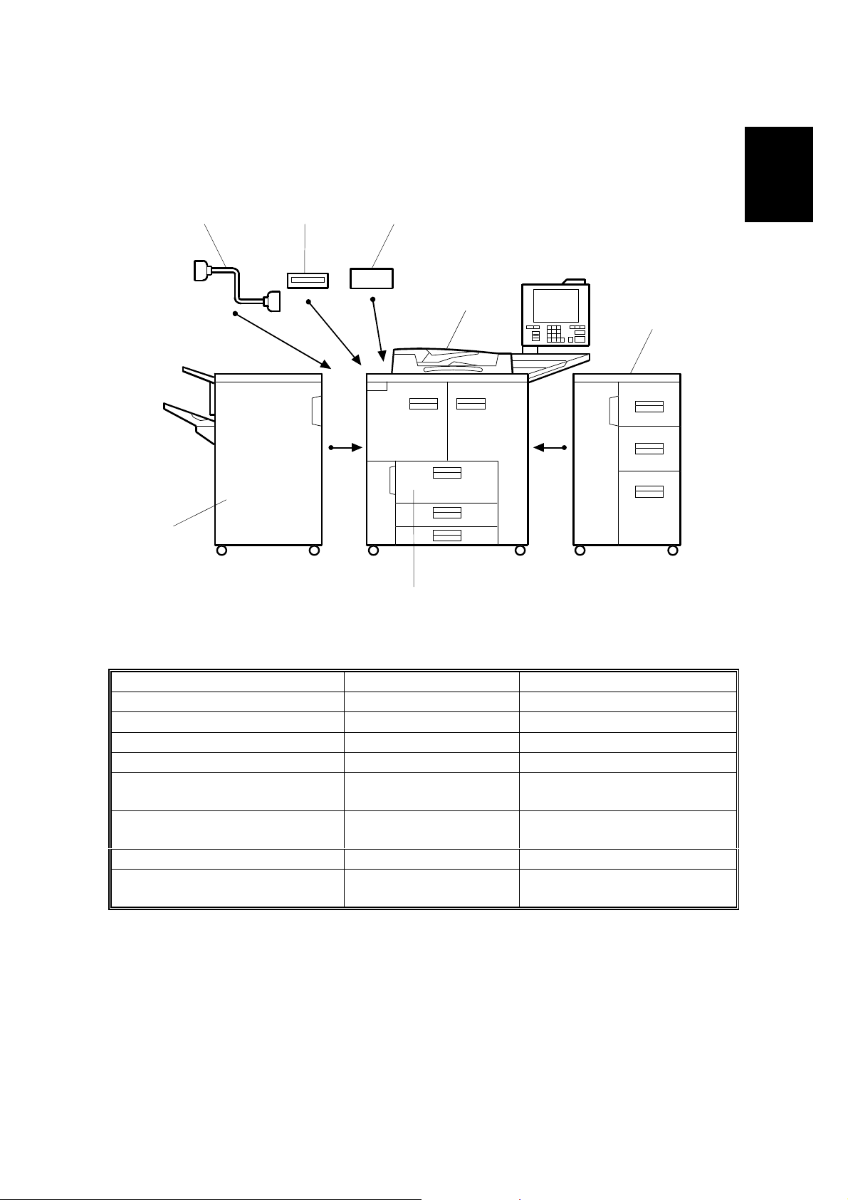
1.2 MACHINE CONFIGURATION
46 5
1
3
Overall
Information
2
7
Item Machine Code No.
Mainframe A294 1
Finisher B302 2
LCT B303 3
Interface Kit Type 850: * B327 4
A3/DLT Tray Kit Type 850
CD-RW
(CDROM reader/writer): *
Punch Unit A812-30, 31, 32, 57, 67 Inside the Finisher
Connector
(for the Tandem Copy feature): *
*: When the CD-RW and/or the copy connector cable are/is installed, the interface kit is
required.
B331
B334 5
B328 6
Replaces the tandem LCT
A294V502.WMF
7
1-5
Page 18
COMPONENT LAYOUT 22 October 1999
1.3 COMPONENT LAYOUT
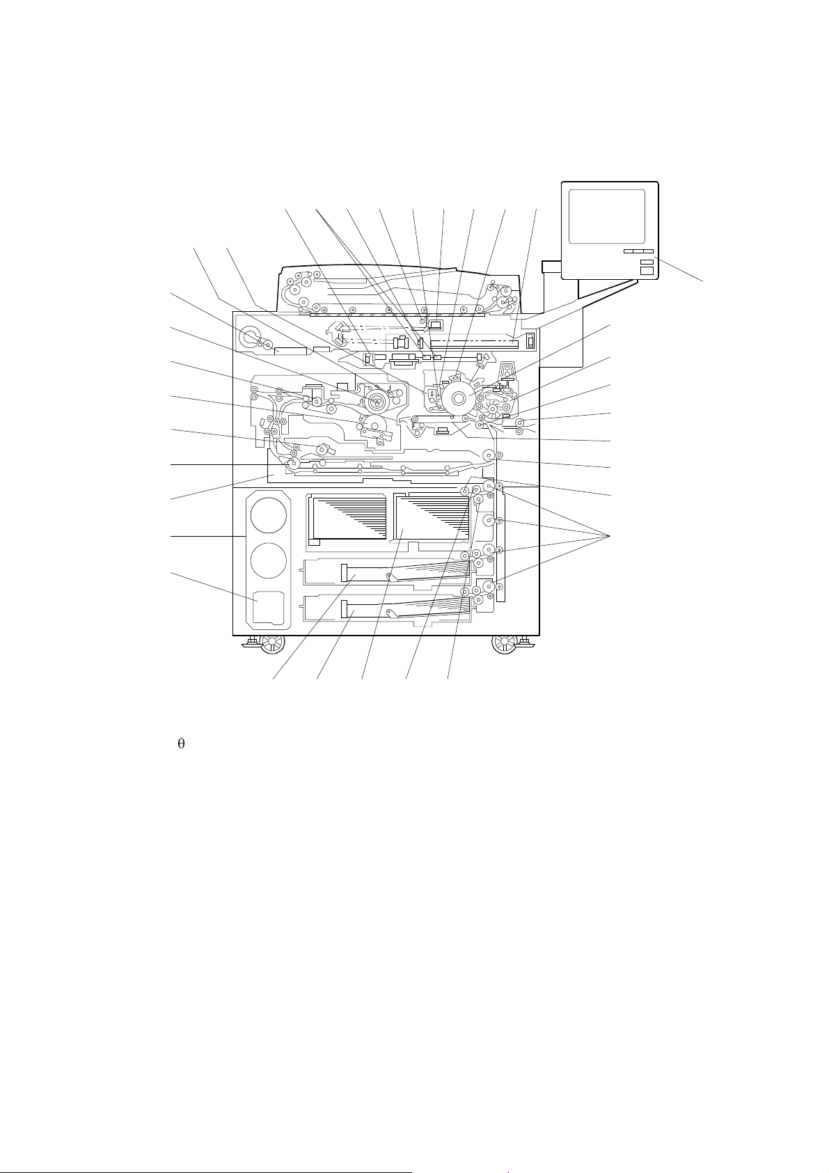
1.3.1 COPIER ENGINE
8
96 753 41 2
3433
32
31
30
29
28
27
26
25
24
10
11
12
13
14
15
16
17
18
23 22 21 20 19
1. Laser Diode Board
2. fq Lenses
3. Sensor Board Unit
4. Exposure Lamp
5. Cleaning Brush
6. Lamp Regulator
7. Cleaning Blade
8. Charge Corona Unit
9. System Image Contro l Unit
10. Color LCD
11. Drum
12. Development Unit
13. Registration Roller
14. LCT Relay Roller
15. Transfer Belt Unit
16. Relay Roller
17. Pick-up Roller
A294V101.WMF
18. Vertical Transport Rollers
19. Separation Roller
20. Feed Roller
21. 1st Tray (Tandem, 1,000 sheets each)
22. 2nd Tr ay (500 sheets)
23. 3rd Tray (500 sheets)
24. Used Toner Bottle
25. Toner Bank Unit
26. Duplex Tr ay
27. Inverter Unit Paper Exit Roller
28. Inverter Feed Roller
29. Pressure Roller
30. Paper Cooling Pipe
31. Hot Roller
32. Motor Control Unit
33. Oil Supply & Cleaning Web
34. Drum Unit
1-6
Page 19
22 October 1999 COMPONENT LAYOUT
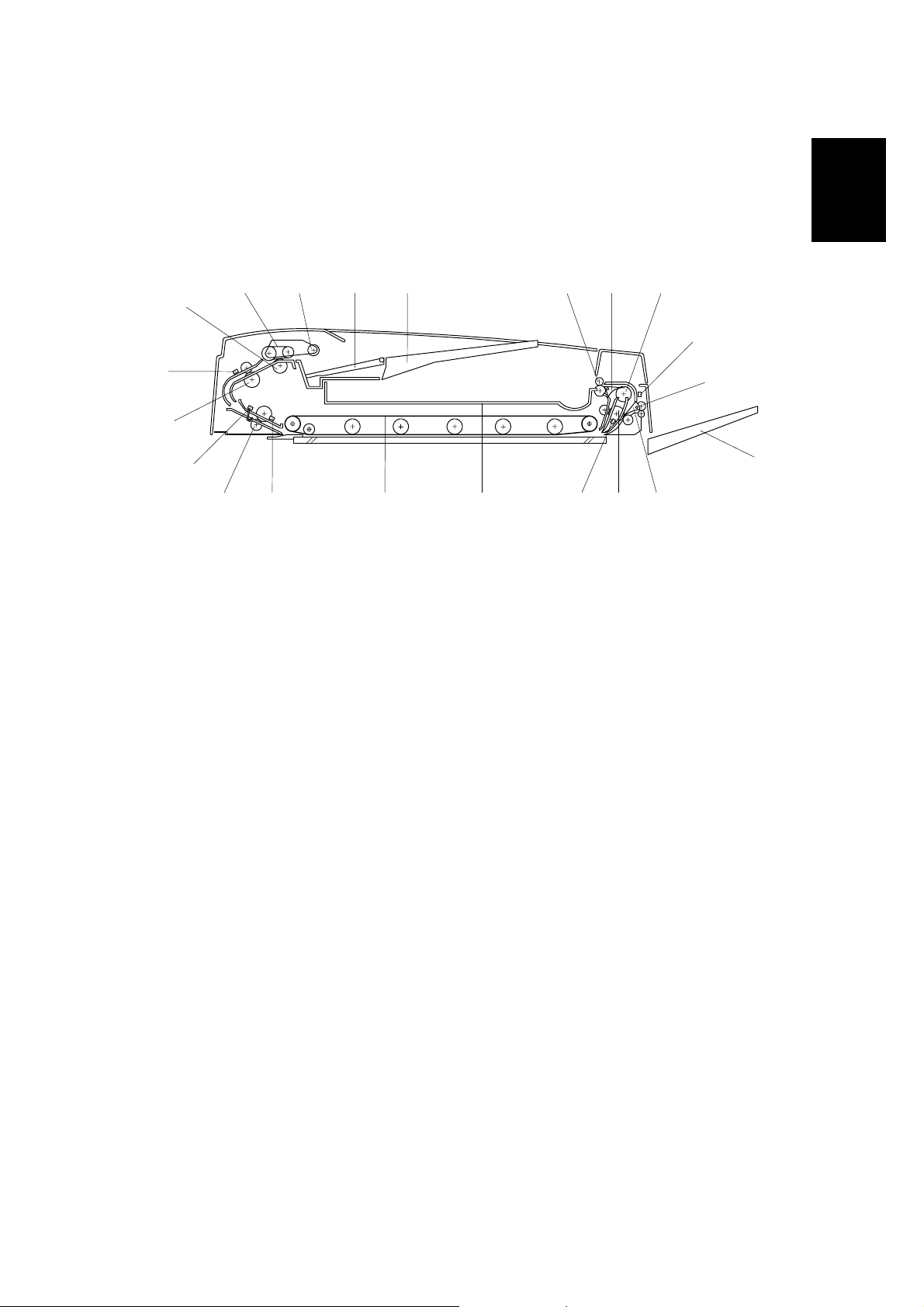
1.3.2 ADF
Overall
Information
1
21
20
19
18 17 1213141516
1. Separation Roller
2. Feed Belt
3. Pick-up Roller
4. Bottom Plate
5. Original Tray
6. Upper Tray Exit Roller
7. Inverter Gate
8. Inverter Guide Roller
9. Inverter Sensor
10. Right Tray Exit Roller
11. Right Exit Tray
7
12. Exit Gate
13. Inverter Roller
14. Exit Sensor
15. Upper Exit Tray
16. Transport Belt
17. Registration Sensor
18. Lower Transport Roller
19. Width Sensor
20. Upper T ransport Roller
21. Entrance Sensor
863425
B301V001.WMF
9
10
11
1-7
Page 20
PAPER PATH 22 October 1999
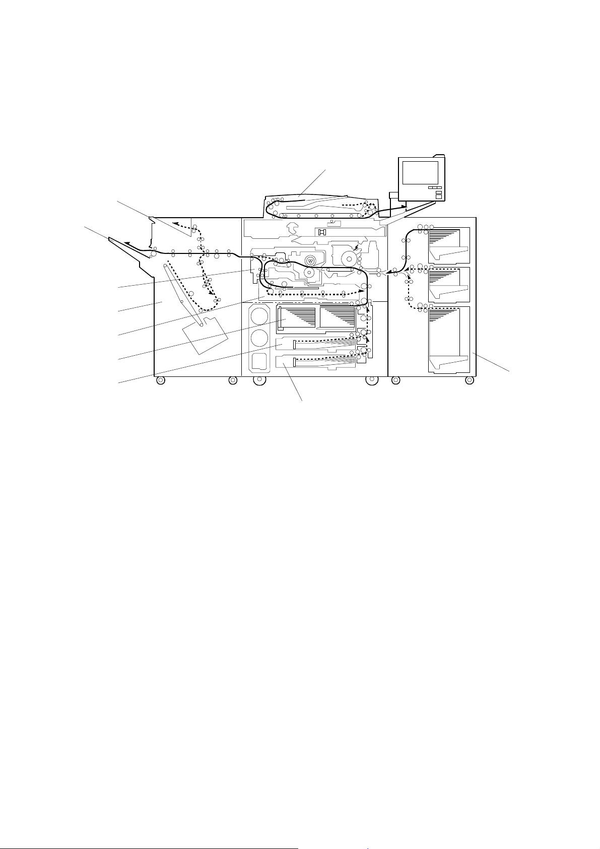
1.4 PAPER PATH
1
10
9
8
7
6
5
4
1. ADF
2. Optional LCT
3. Tray 3 (1,500-sheet LCT)
4. Tray 2 (550-sheet Tray)
5. Tray 1 (Tandem Tray)
2
3
A294V504.WMF
6. Duplex Unit
7. Finisher
8. Inverter Unit
9. Shift Tray
10. Upper T ray
1-8
Page 21
22 October 1999 COPY PROCESS
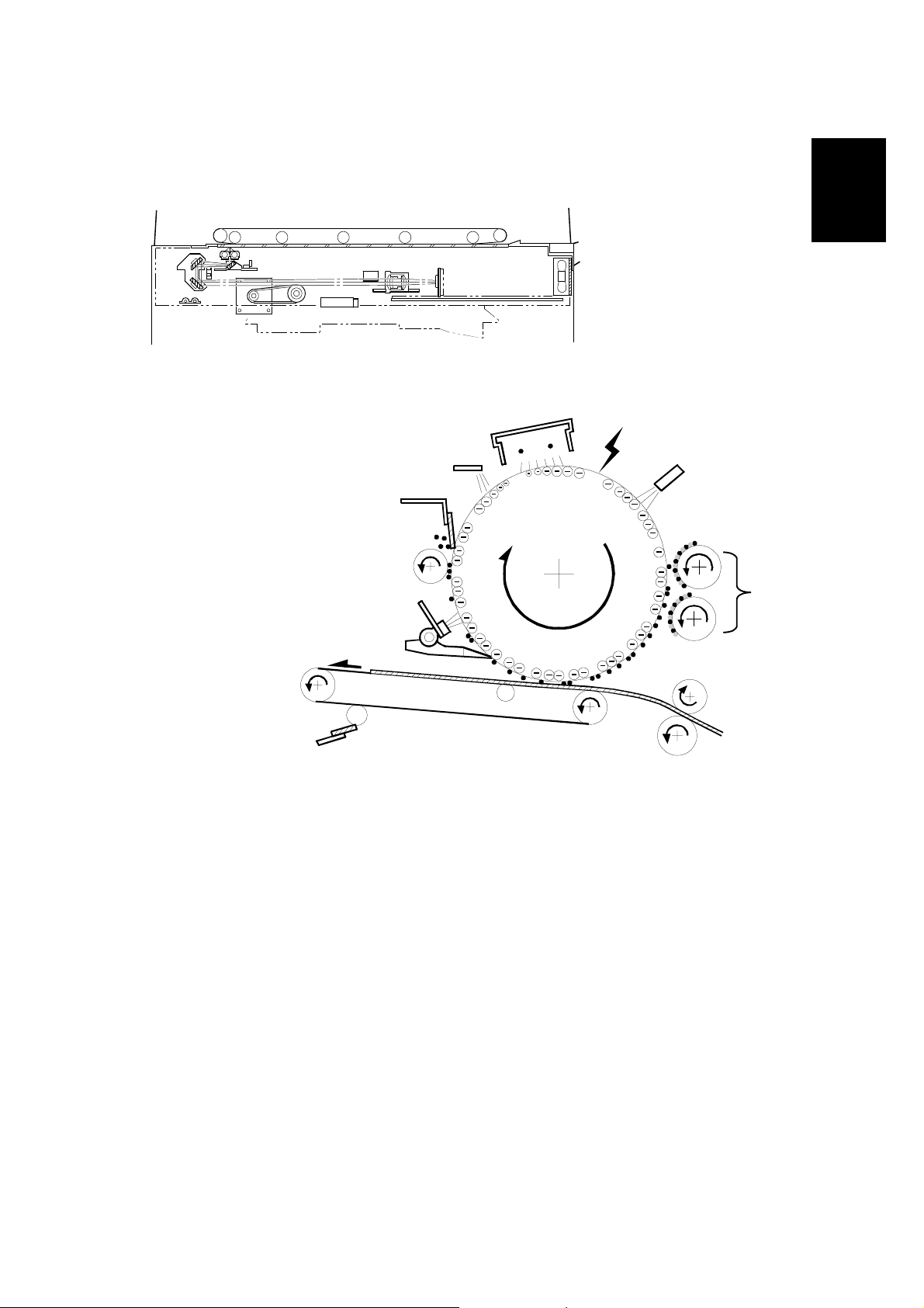
1.5 COPY PROCESS
1
A229V508.WMF
Overall
Information
2
10
3
4
9
8
7
6
A229V510.WMF
1. EXPOSURE
A xenon lamp exposes the original. Light reflected from the original passes to
the CCD, where it is converted into an analog data signal. This data is
converted to a digital signal, processed, and stored in the memory. At the time
of printing, the data is retrieved and sent to the laser diode. For multi-copy runs,
the original is scanned once only and stored to the hard disk.
5
2. DRUM CHARGE
An OPC (organic photoconductor) drum is used in this machine. In the dark,
the charge corona unit gives a negative charge to the drum. The grid plate
ensures that corona charge is applied uniformly. The charge remains on the
surface of the drum because the OPC layer has a high electrical resistance in
the dark.
1-9
Page 22

COPY PROCESS 22 October 1999
3. LASER EXPOSURE
The processed data from the scanned original is retrieved from the hard disk
and transferred to the drum by four laser beams, w hic h for m an electr ost ati c
latent image on the drum surface. The amount of charge remaining as a latent
image on the drum depends on the laser beam intensity, which is controlled by
the laser diode board (LDB).
4. DRUM POTENTIAL SENSOR
The drum potential sensor detects the electric potential on the drum to correct
various process control elements.
5. DEVELOPMENT
The magnetic developer br ush on the development rollers comes in contac t
with the latent image on the drum surface. Toner particles are electrostatically
attracted to the areas of the drum surface where the laser reduced the negative
charge on the drum.
6. IMAGE TRANSFER
Paper is fed to the area between the drum surface and the transfer belt at the
proper time to align the copy paper and the developed image on the drum.
Then, the transfer bias roller and brush apply a high positive charge to the
reverse side of the paper through the transfer belt. This positive charge pulls
the toner particles from the drum to the paper. At the same time, the paper is
electrically attracted to the transfer belt.
7. PAPER SEPARATION
Paper separates from the drum as a result of the electrical attraction between
the paper and the transfer belt. The pick-off pawls also help separate the paper
from the drum.
8. ID SENSOR
The laser forms a sensor pattern on the drum surface. The ID sensor measures
the reflectivity of the pattern. The output signal is one of the factors used for
toner supply control.
9. CLEANING
The cleaning brush removes toner remaining on the drum after image transfer
and the cleaning blade scrapes off all remaining toner.
10. QUENCHING
The light from the quenching lamp electrically neutralizes the charge on the
drum surface.
1-10
Page 23
22 October 1999 DRIVE LAYOUT
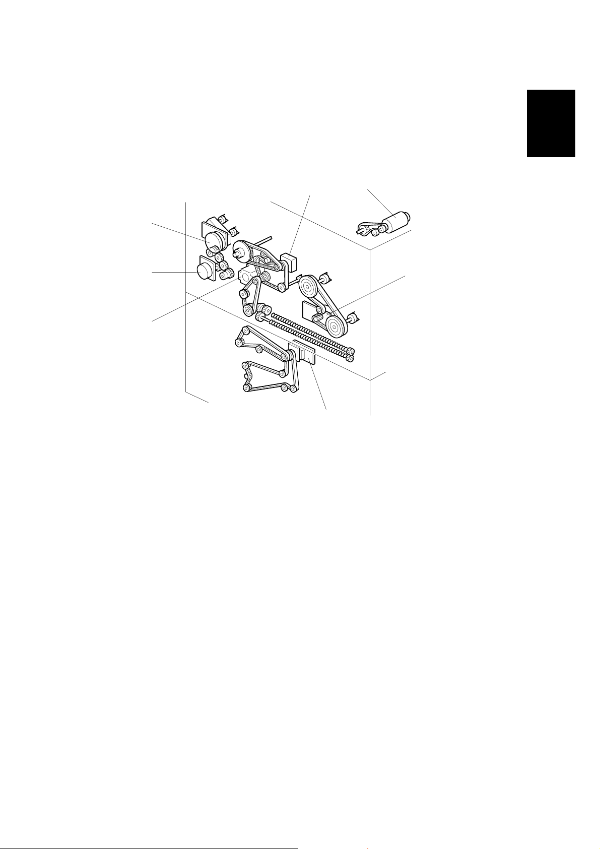
1.6 DRIVE LAYOUT
1.6.1 COPIER ENGINE
Overall
Information
1
2
7
6
3
5
4
A294V501.WMF
1. Drum Motor
2. Scanner Motor
3. Fusing/Duplex Motor
4. Paper Feed Motor
5. Registrat ion Motor
6. Relay Motor
7. Development Motor
1-11
Page 24
DRIVE LAYOUT 22 October 1999
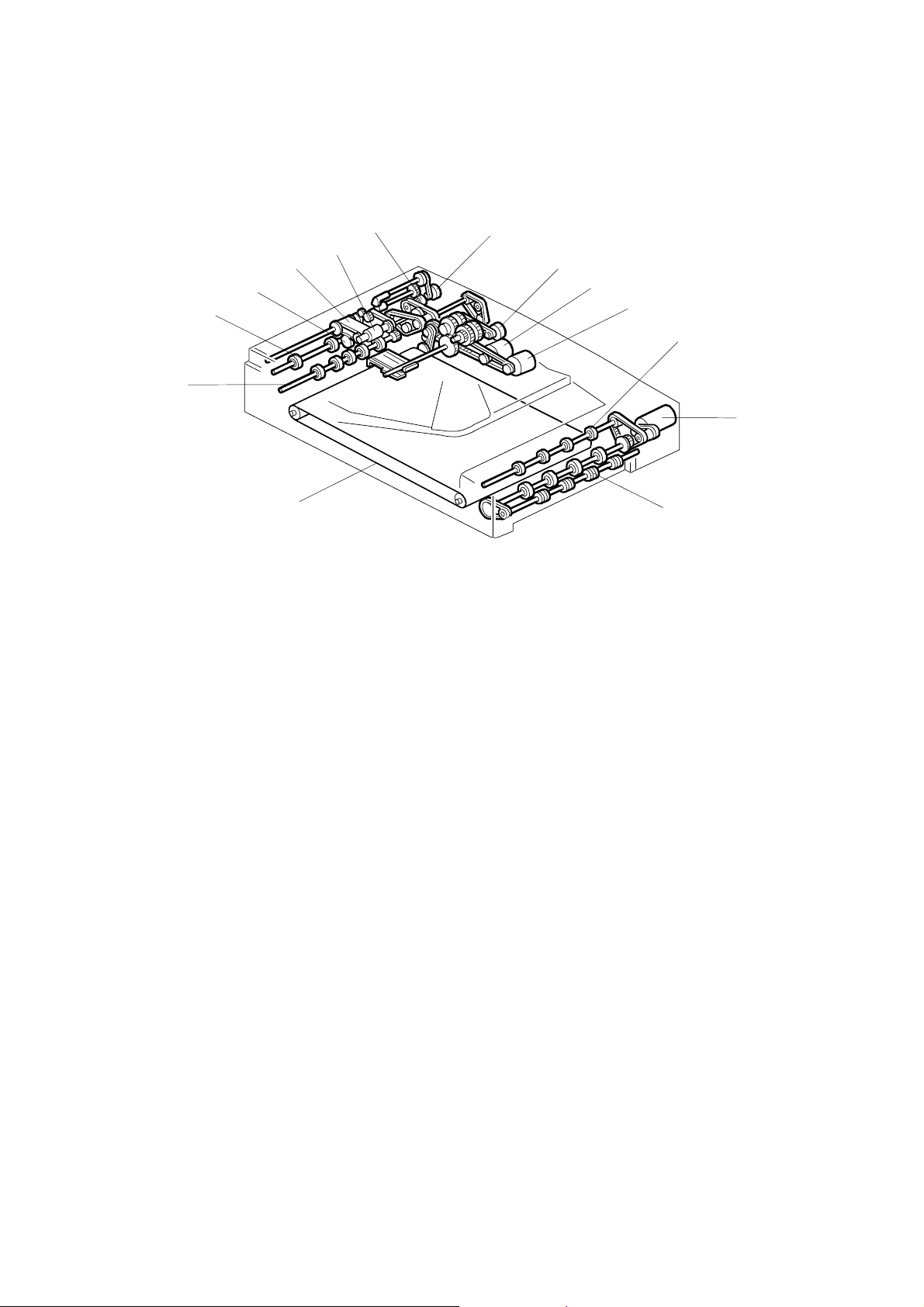
1.6.2 ADF
14
13
12
11
10
1
2
3
4
5
9
6
8
B301V101.WMF
7
1. Pick-up Motor
2. Bottom Plate Motor
3. Feed-in Motor
4. Transport Motor
5. Upper Exit Roller
6. Feed-out Motor
7. Right Exit Roller
8. Transport Belt
9. Lower Transport Roller
10. Upper T ransport Roller
11. Separation Roller
12. Feed Belt
13. Pick-up Roller
14. Feed-in Clutch
1-12
Page 25

22 October 1999 ELECTRICAL COMPONENT DESCRIPTIONS
1.7 ELECTRICAL COMPONENT DESCRIPTIONS
Refer to the electrical component layout on the reverse side of the point-to-point
diagram for the location of the components using the symbols and index numbers.
1.7.1 COPIER ENGINE
Symbol Name Function
Motors
M1 Scanner Drives the 1st and 2nd scanners.
M2 Polygonal Mirror Turns the polygonal mirror.
M3 Drum Drives the drum, cleaning unit, and transfer belt unit.
M4 Development Drives the development unit.
M5 Toner Supply Supplies the toner to the toner hopper.
M6
M7
M8
M9
M10
M11
M12
M13
M14 Relay Drives the upper relay roller and the LCT relay roller.
M15
M16
M17
M18 Registration Drives the registration r oller s.
M19
M20
M21
M22 Optics Cooling Fan Removes heat from the scanner optics unit.
M23
M24 LDB Cooling Fan Removes heat from around the LDB.
Toner Bank Drives the toner transport coil, which feeds fresh
toner from the toner bank to the toner supply cylinder.
Upper Toner Bottle
Upper Bottle Cap Opens and closes the inner cap of the upper toner
Lower Toner Bottle Rotates the lower toner bottle to supply toner to the
Lower Bottle Cap Opens and closes the inner cap of the lower toner
Charge Corona Wire
Cleaner
Fusing/Duplex Drives the fusing unit, duplex unit, inverter unit, and
Paper Feed Drives the paper feed, separation, pick-up, lower
1st Tray Lift
2nd Tray Lift Raises and lowers the bottom plate in the 2nd paper
3rd Tray Lift Raises and lowers the bottom plate in the 3rd paper
Oil Supply/Cleaning
Web
Rear Fence Drive
Jogger Drives the jogger fences to square the paper stack in
Polygonal Mirror
Motor Cooling Fan
Rotates the upper toner bottle to supply toner to the
toner entrance tank.
bottle.
toner entrance tank.
bottle.
Drives the charge corona wire cleaner.
paper exit rollers.
relay, and vertical transport rollers.
Raises and lowers the bottom plate in the 1st paper
tray.
tray.
tray.
Drives the oil supply/cleaning web.
Moves the paper stack in the left tandem tray to the
right tandem tray.
the duplex unit.
Removes heat from around the polygonal mirror
motor.
Overall
Information
1-13
Page 26

ELECTRICAL COMPONENT DESCRIPTIONS 22 October 1999
Symbol Name Function
M25 SICU Cooling Fan Removes heat from around the SICU.
M26 Drum Cooling Fan Removes heat from the drum.
M27
M28
M29
Development Unit
Cooling Fan 1
Development Unit
Cooling Fan 2
Paper Cooling Pipe
Fan
Removes heat from the development unit.
Removes heat from the development unit.
Removes heat from the paper cooling pipe.
M30 Duplex Cooling Fan Rem oves heat from around the duplex unit.
M31 Exhaust Fan Removes heat from around the fusing unit.
M32 Steam Removal Fan Removes water vapour from around the fusing unit.
M33 PSU Cooling Fan 1 Removes heat from the PSU.
M34 PSU Cooling Fan 2 Removes heat from the PSU.
Sensors
S1
S2
S3
S4
Scanner HP Informs the CPU when the 1st and 2nd scanners are
at home position.
Original Width
Detects original width.
This is one of the APS (Auto Paper Select) sensors.
Original Length 1 Detect s original length.
This is one of the APS (Auto Paper Select) sensors.
Original Length 2 Detect s original length.
This is one of the APS (Auto Paper Select) sensors.
S5 Drum Potential Detects the drum surface potential.
S6 Toner Density (TD) Detects the amount of toner in the developer.
S7
Image Density (ID)
Detects the density of the ID sensor pattern on the
drum.
S8 Toner Hopper Detects toner in the toner hopper.
S9 Toner Supply Motor Monitors the toner supply motor.
S10 Upper Toner Bottle Detects when the upper toner bottle is set.
S11 Lower Toner Bottle Detects when the lower toner bottle is set.
S12
S13
S14
Upper Bottle Inner
Cap
Lower Bottle Inner
Cap
Toner Collection
Bottle
Detects when the inner cap of the upper toner bottle
is opened.
Detects when the inner cap of the lower toner bottle is
opened.
Detects when the waste toner collection bottle is set.
S15 Toner Overflow Detects when the waste toner collection bottle is full.
S16 Toner Near End Detects toner near end in the toner bank unit.
S17
S18
S19
S20
1st Paper Feed Controls the 1st paper feed clutch on/off timing and
the 1st pick-up solenoid off timing.
2nd Paper Feed
Controls the 2nd paper feed clutch on/off timing and
the 2nd pick-up solenoid off timing.
3rd Paper Feed Controls the 3rd paper feed clutch on/off timing and
the 3rd pick-up solenoid off timing.
1st Tray Lift Detects when the paper in tray 1 is at the correct
height for paper feed.
1-14
Page 27

22 October 1999 ELECTRICAL COMPONENT DESCRIPTIONS
Symbol Name Function
S21
S22
2nd Tray Lift Detects when the paper in tray 2 is at the correct
height for paper feed.
3rd Tray Lift Detects when the paper in tray 3 is at the correct
height for paper feed.
S23 1st Paper End Informs the CPU when tray 1 runs out of paper.
S24 2nd Paper End Informs the CPU when tray 2 runs out of paper.
S25 3rd Paper End Informs the CPU when tray 3 runs out of paper.
S26
S27
S28
S29
S30
S31
S32
S33
S34
S35
S36
S37
S38
Rear Fence HP Informs the CPU when the tandem tray rear fence is
in the home position.
Rear Fence Return
Informs the CPU when the tandem tray rear fence is
in the return position.
Front Side Fence
Open
Front Side Fence
Closed
Rear Side Fence
Open
Rear Side Fence
Closed
Detects whether the tandem tray front side fence is
opened.
Detects whether the tandem tray front side fence is
closed.
Detects whether the tandem tray rear side fence is
opened.
Detects whether the tandem tray rear side fence is
closed.
Base Plate Down Detects when the bottom plate is completely lowered,
to stop the 1st tray lift motor.
1st Tray Paper
Detects the paper height in the 1st tray.
Height 1
1st Tray Paper
Detects the paper height in the 1st tray.
Height 2
1st Tray Paper
Detects the paper height in the 1st tray.
Height 3
1st Tray Paper
Detects the paper height in the 1st tray.
Height 4
Left 1st Tray Paper
Detects whether there is paper in the left side of the
1st tray.
Right 1st Tray Paper Detects whether there is paper in the right side of the
1st tray, allowing the tray to lift if paper is present.
S39 Duplex Inverter Detects misfeeds.
S40
Duplex Entrance Detects the leading and trailing edges of the paper to
determine the reverse roller solenoid on or off timing.
S41 Duplex Transport 1 Detects the position of paper in the duplex unit.
S42 Duplex Transport 2 Detects the position of paper in the duplex unit.
S43 Duplex Transport 3 Detects the position of paper in the duplex unit.
S44
Duplex Jogger HP Detects if the duplex jogger fences are at the home
position or not.
S45 LCT Relay Detects misfeeds.
S46 Relay Detects misfeeds.
S47
S48
Registration
Guide Plate Position
Detects misfeeds and controls registration clutch
on/off timin g.
Detects whether the registration guide plate is open
or closed.
Overall
Information
1-15
Page 28

ELECTRICAL COMPONENT DESCRIPTIONS 22 October 1999
Symbol Name Function
S49
Oil Supply/Cleaning
Web End
Detects when the oil supply/cleaning web has been
used up.
S50 Fusing Exit Detects misfeeds.
S51 Exit Detects misfeeds.
Switches
SW1
SW2
SW3
SW4
SW5
SW6
SW7
SW8
SW9
SW10
SW11
Main Power Provides power to the machine. If this is off, there is
no power supplied to the machine.
Right Front Door
Safety 1
Right Front Door
Safety 2
Right Front Door
Cuts the +24 V dc power line for the fusing/duplex
motor.
Detects if the front door is open or not, and cuts the
+24 V dc power line for the IOB.
Cuts the +5 V LD dc power line.
Safety 3
Right Front Door
Cuts the +5 V LD dc power line.
Safety 4
Left Front Door
Safety 1
Left Front Door
Safety 2
Left Front Door
Cuts the +24 V dc power line for the fusing/duplex
motor.
Detects if the front door is open or not, and cuts the
+24 V dc power line for the IOB.
Cuts the +5 V LD dc power line.
Safety 3
Left Front Door
Cuts the +5 V LD dc power line.
Safety 4
2nd Tray Paper Size Determines the size of paper in tray 2. Also detects
when the tray has been placed in the machine.
3rd Tray Paper Size Det er m ines the size of paper in tray 3. Also detects
when the tray has been placed in the machine.
Solenoids
SOL1
SOL2
SOL3
SOL4
SOL5
SOL6
SOL7
SOL8
SOL9
Transfer Belt Lift Controls the up-down movement of the transfer belt
unit.
1st Pick-up Controls the up-down movement of the pick-up roller
in tray 1.
2nd Pick-up
Controls the up-down movement of the pick-up roller
in tray 2.
3rd Pick-up
Controls the up-down movement of the pick-up roller
in tray 3.
1st Separation
Roller
2nd Separation
Roller
3rd Separation
Roller
Controls the up-down movement of the separation
roller in tray 1.
Controls the up-down movement of the separation
roller in tray 2.
Controls the up-down movement of the separation
roller in tray 3.
Front Side Fence Opens and closes the front side fence in the tandem
tray.
Rear Side Fence Opens and closes the rear side fence in the tandem
tray.
1-16
Page 29

22 October 1999 ELECTRICAL COMPONENT DESCRIPTIONS
Symbol Name Function
SOL10
SOL11
SOL12
SOL13
SOL14
SOL15
SOL16
Tandem Tray
Connect
Left 1st Tray Lock Locks the left tandem tray while paper is being
Duplex Inverter Gate
Reverse Roller Controls the up-down movement of the reverse roller
Inverter Guide Plate Controls the up-down movement of the inverter feed
Guide Plate
Inverter Gate Moves the junction gate to direct copies to the
Connects/disconnects the two halves of the tandem
tray.
transported from left tray to right tray.
Moves the junction gate to direct copies to the duplex
tray or to the paper exit.
in the duplex unit.
guide plate in the duplex unit.
Opens the guide plate when a paper misfeed occurs
around this area.
duplex/inverter unit or to the paper exit unit.
Magnetic Clutches
MC1
MC2
Toner Supply Coil Transfers drive from the toner bank motor to the toner
transport coil, to transport toner towards the hopper.
Toner Supply Roller
Turns the toner supply roller to supply toner from the
toner hopper to the development unit.
MC3 1st Paper Feed Starts paper feed from tray 1.
MC4 2nd Paper Feed Starts paper feed from tray 2.
MC5 3rd Paper Feed Starts paper feed from tray 3.
MC6
MC7
MC8
MC9
MC10
MC11
MC12
MC13
MC14
Inverter Exit Roller
Duplex Transport Drives the duplex transport rollers to transport the
Duplex Feed Starts paper feed out of the duplex tray back into the
1st Vertical
Transport
2nd Vertical
Transport
3rd Vertical
Transport
Upper Relay
LCT Relay Drives the relay rollers for paper feed into the
Lower Relay Drives the lower relay rollers (between paper trays 1
Releases the drive from the inverter exit roller in the
duplex unit.
paper to the duplex feed rollers.
machine via to the relay rollers.
Drives the 1st vertical transport rollers.
Drives the 2nd vertical transport rollers.
Drives the 3rd vertical transport rollers.
Drives the upper relay rollers (between tray1 and the
registration rol lers)
machine from the LCT.
and 2).
Overall
Information
PCBs
PCB1
PCB2
BCU (Base Engine
Control Unit)
SICU (Scanner
Image Control Unit)
Controls all base engine functions both directly and
through other control boards.
Controls image processing, the laser diode, and the
polygonal mirror motor.
1-17
Page 30

ELECTRICAL COMPONENT DESCRIPTIONS 22 October 1999
Symbol Name Function
PCB3
PCB4
PCB5
PCB6
PSU
(Power Supply Unit)
IOB
(Input/Output Board)
SBU
(Sensor Board Unit)
MCU
(Motor Control Unit)
Provides dc power to the system and ac power to the
fusing lamp and heaters.
Controls the paper feed components.
Contains the CCD, and outputs a video signal to the
SBICU board.
Drives the scanner motor.
PCB7 Lamp Regulator Provides dc power to the exposure lamp.
PCB8
Polygonal Mirror
Motor Control
Drives and controls the polygonal mirror motor.
PCB9 LDB Controls the laser diode.
PCB10 AC Dr ive Drives the ac components.
PCB11 O per ation Panel Controls the components of the operation panel.
PCB12 O per ation Key Controls the operation switch.
Lamps
L1
Exposure Lamp Applies high intensity light to the original for
exposure.
L2 Fusing Lamp 1 Provides heat to the hot roller.
L3 Fusing Lamp 2 Provides heat to the hot roller.
L4 Fusing Lamp 3 Provides heat to the hot roller.
L5
Quenching Neutralizes any charge remaining on the drum
surface after cleaning.
Power Packs
PP1
Charge/bias/grid
Provides high voltage for the charge corona wires,
grid plate, and the development roller.
PP2 Transfer Pr ovides hig h voltage for the transfer belt.
Others
CB1
H1
Circuit Breaker Provides back-up high current protection for the
electrical components.
Optics
Anti-Condensation
Turns on when the main switch is off to prevent
moisture from forming on the optics.
(option)
H2
H3
H4
HDD1
HDD2
Drum (option) Turns on when the main switch is off to prevent
moisture from forming around the drum.
Tray Heater 1
(option)
Tray Heater 2
(option)
Turns on when the main switch is off to keep paper
dry in the paper tray.
Turns on when the main switch is off to keep paper
dry in the paper tray.
HDD Scanned image data is compressed and held here
temporarily.
HDD Scanned image data is compressed and held here
temporarily.
NF1 Noise Filter Removes noise from the power line.
1-18
Page 31

22 October 1999 ELECTRICAL COMPONENT DESCRIPTIONS
Symbol Name Function
SD1
Laser
Synchronization
Detects the laser beam at the start of the main scan.
Detector
TC1 Total Counter Counts the number of copies.
TF1
Fusing Thermofuse
Opens the fusing lamp circuit if the fusing unit
overheats.
TH1 Fusing Thermistor Detects the temperature of the hot roller.
1.7.2 ADF
Symbol Name Function Index No.
Motors
M1 Pick-up Moves the pick-up roller up and down. 3
M2
Feed-in
M3 Transport Belt Drives the transport belt. 9
M4 Feed-out Drives the exit and inverter rollers. 14
M5 Bottom Plate Moves the bottom plate up and down. 7
Drives the feed belt, and the separation,
pick-up, and transport rollers.
8
Overall
Information
Sensors
APS Start
S1
Informs the CPU when the DF is opened
and closed (for platen mode) so that the
original size sensors in the copier can
check the original size.
S2 DF Position Detects whether the DF is lifted or not. 13
S3
S4
S5
S6
Original Set
Bottom Plate HP Detects whether the bottom plate is in
Bottom Plate
Position
Pick-up Roller HP
Detects whether an original is on the
table.
the down position or not.
Detects when the original is at the correct
position for feeding.
Detects whether the pick-up roller is up
or not.
Entrance Detects when to restart the pick-up motor
to lift up the pick-up roller, detects when
S7
to change the feed motor direction,
detects the trailing edge of the original to
finish checking the original length, and
checks for misfeeds.
Registration Detects the leading edge of the original
S8
to check the original length, detects when
to stop the original on the exposure
glass, and checks for misfeeds.
S9 Original Width 1 Detects the original width. 22
S10 Original Width 2 Detects the original width. 23
12
19
20
4
2
26
21
1-19
Page 32

ELECTRICAL COMPONENT DESCRIPTIONS 22 October 1999
Symbol Name Function Index No.
S11 Original Width 3 Detects the original width. 24
S12 Original Length Detects the original length. 25
S13
Exit
Detects when to stop the transport belt
motor and checks for misfeeds.
18
Inverter Detects when to turn the inverter gate
S14
and exit gate solenoids off and checks
17
for misfeeds.
S15
S16
Feed Cover
Exit Cover Detects whether the exit cover is open or
Detects whether the feed cover is open
or not.
not.
5
15
Solenoids
SOL1 Exit Gate Opens and closes the exit gate. 16
SOL2 Inverter Gate Opens and closes the inverter gate. 11
Magnetic Clutches
MC1
Feed-in
Drives the feed belt, separation roller,
and pick-up roller.
1
PCBs
PCB1
PCB2
DF Main Contr ols the DF and communicates with
the main copier boards.
DF Indicator Indicates whether an original has been
placed in the feeder, and indicates
whether SADF mode has been selected.
10
6
1-20
Page 33

22 October 1999 DOCUMENT FEEDER
2. DETAILED SECTION DESCRIPTIONS
2.1 DOCUMENT FEEDER
2.1.1 PICK-UP ROLLER RELEASE
[F]
[E]
[B]
[C]
[A]
[D]
Detailed
Descriptions
B301D103.WMF
When the original set sensor is of f (no original on the original tray), th e pick-up
roller stays in the up position.
When the original set sensor turns on (or when the trailing edge of a page passes
the entrance sensor while pages remain on the original tray), the pick-up motor [A]
turns on. The cam [B] rotates away from the pick-up roller release lever [C]. The
lever then rises and the pick-up roller [D] drops onto the original.
When the original reache s the entrance sensor, the pi ck-up motor turns on again.
The cam pushes the lever down, and the pick-up roller rises until the pick-up roller
HP sensor [E] detects the actuator [F].
2-1
Page 34

DOCUMENT FEEDER 22 October 1999
2.1.2 BOTTOM PL ATE LIFT
[F]
[E]
[B]
[A]
[C]
[D]
[B]
[F]
B301D105.WMF
When an original is placed on the original tray, the original set sensor [ A] turns on,
the pick-up roller [B] drops on to the original, and the bottom plate position sensor
[C] turns off. Then the bottom plate motor [D] turns on and lifts the bottom plate [E]
by raising the lift lever [F] until the bottom plate position sensor turns on.
The level of the pick-up roller drops as the stack of originals becomes smaller, and
eventually, the bottom plate position sensor [C] turns off. Then, the bottom plate
motor turns on and lifts the bottom plate until the bottom plate position sensor turns
on. This keeps the original at the correct height for feeding.
2-2
Page 35

22 October 1999 DOCUMENT FEEDER
2.1.3 PICK-UP AND SEPARATION
[D]
[A]
[E]
[B]
[C]
[A]
[B]
B301D102.WMF
[C]
B301D506.WMF
The original separation system is a Feed and Reverse Roller (FRR) system. The
pick-up roller [A], feed belt [B], and separation roller [C] are driven by the feed-in
motor [D].
Detailed
Descriptions
To drive this mechanism, the feed-in motor [D] and feed-in clutch [E] turn on.
When two sheets of originals ar e fed by the pick-up roller, the separa tion roller
turns in the opposite direction to the feed belt and the 2nd sheet is pushed back to
the original tray. When there is only one sheet between the feed belt and
separation roller, the separation roller rotates in the same direction as the feed belt.
This is because the separation roller contains a torque limiter.
2-3
Page 36

DOCUMENT FEEDER 22 October 1999
2.1.4 ORIGINAL FEED
[D]
[B]
[A]
[C]
B301D109.WMF
When the leading edge of the original turns the entrance sensor [A] on, the feed-in
clutch [B] turns off and the drive for the feed belt is released. The original is fed by
the transport rollers [C].
At the same time, the pick-up motor starts again and the pick-up roller [D] is lifted
up. When the pick-up roller HP sensor turns on, the pick-up motor stops (see Pickup Roller Release).
2-4
Page 37

22 October 1999 DOCUMENT FEEDER
2.1.5 ORIGINAL SIZE DETECTION
[G]
[F]
B301D104.WMF
[A]
[E]
[B]
Detailed
Descriptions
[C]
[D]
B301D503.WMF
The DF detects the original size by combining the readings of original length
sensor [A], and original width sensors-1 [B], -2 [C], and -3 [D].
Original Length
The original length sensor and the disk [E] (connected to the transport roller)
generate a pulse signal. The CPU counts pulses, starting when the leading edge of
the original turns on the registration sensor [F], until the trailing edge of the original
turns off the entrance sensor [G].
Original Width
The CPU detects original width using three original width sensors -1, -2, -3 as
shown above. Three small circles on the diagram indicate the positions of the
sensors.
2-5
Page 38

DOCUMENT FEEDER 22 October 1999
2.1.6 ORIGINAL TRANSPORT
[B]
[A]
[C]
B301D106.WMF
[E]
[D]
3.5 mm
B301D509.WMF
The transport belt [A] is driven by the transport belt motor [B]. The transport belt
motor starts when the copier sends an original feed-in signal.
Inside the transport belt are six pressure rollers which maintain the correct
pressure between the belt and original. The pressure roller [C] closest to the left
original scale is made of rubber for the stronger pressure needed for thick originals.
The other rollers are sponge rollers.
Normally, originals are manually placed at the left rear corner, so an original [D] fed
from the DF must also be at this position. But if the original is fed along the rear
scale [E], original skew, jam, or wrinkling may occur.
To prevent such problems, the original transfer position is set to 3.5 mm away from
the rear scale as shown. The 3.5 mm gap is compensated for by changing the
starting position of the main scan.
2-6
Page 39

22 October 1999 DOCUMENT FEEDER
2.1.7 ORIGINAL SKEW CORRECTION
[A]
7 mm
B301D500.WMF
Detailed
Descriptions
The transport belt motor remains energized to carry the original about 7 mm past
the left scale [A] (see the middle drawing). Then the motor stops and reverses to
feed the original back against the left scale (see the bottom drawing). This forces
the original to hit the left scale, which aligns the trailing ed ge to minim ize original
skew on the exposure glass.
If thin original mode is selected, the original is not forced back against the left
scale. This is to prevent damage to the original.
After a two-sided original has been inverted to copy the 2nd side, it is fed in from
the inverter against the left scale (see the bottom drawing; the top two drawings do
not apply in this mode).
The amount of reverse feed against the left scale can be adjusted with SP modes.
2-7
Page 40

DOCUMENT FEEDER 22 October 1999
2.1.8 ORIGINAL INVERSION AND FEED-OUT
General Operation
[A]
B301D107.WMF
When the sca nner reaches the return position, the copier’s CPU sends the feed-out
signal to the DF. When the DF receives the feed-out signal, the transport belt motor
and feed-out motor [A] turn on. The original is then fed out to the exit tray or fed
back to the exposure glass after reversing in the inverter section.
This DF has two exit trays. For single-sided original mode, the original is fed out to
the right exit tray and for double-sided original mode, the original is fed out to the
upper exit tray.
This causes the originals to be fed out in the correct order on the exit trays and
allow the maximum one-to-one copy speed for each mode. The user can change
the exit tray to the upper exit tray for single-sided mode (for example, if there is not
enough space in the room for the right exit tray to be installed). However, one-toone copy speed for this mode is reduced.
2-8
Page 41

22 October 1999 DOCUMENT FEEDER
Original Inversion
[F]
[B]
[E]
[G]
[D]
[A]
[C]
B301D113.WMF
When the DF receives the original invert s ignal from the copier, the transport be lt
motor, feed-out motor, exit gate solenoid [A], and inverter gate solenoid [B] turn on
and the original is fed back to the exposure glass through the inverter roller [C], exit
gate [D], inverter guide roller [E], inverter gate [F], and inverter roller.
Detailed
Descriptions
The transport belt motor turns in reverse shortly after the leading edge of the
original turns on the inverter sensor [G], and feeds the original to the left scale.
2-9
Page 42

DOCUMENT FEEDER 22 October 1999
Original Exit (Single-Sided Original Mode)
[A]
[B]
B301D111.WMF
The exit gate solenoid [A] remains off and the original is fed out to the right exit
tray. The transport belt motor turns off after the exit sensor [B] turns off.
To stack the originals neatly on the exit tray, the feed-out motor speed is reduced
about 30 mm before the trailing edge of the original turns off the exit sensor.
2-10
Page 43

22 October 1999 DOCUMENT FEEDER
Original Exit (Double-Sided Original Mode)
[B]
[D]
[A]
[C]
B301D112.WMF
The exit gate solenoid [A] turns on and the inverter gate solenoid [B] remains off,
and the original is fed out to the upper tray. The transport belt motor turns off when
the trailing edge of the original passes through the exit sensor [C].
To stack the originals neatly on the upper tray, the feed-out motor speed is
reduced shortly after the trailing edge of the original turns off the inverter sensor
[D].
Detailed
Descriptions
2-11
Page 44

DOCUMENT FEEDER 22 October 1999
2.1.9 JAM CONDITIONS
[A]
[D]
[C]
[B]
B301D501.WMF
Feed-in
1. The entrance sensor [A] is still off 500 ms after the feed-in motor turned on.
2. The registration sensor [B] is still not off 300 ms after the feed-in motor speed
increased.
3. The entrance sensor is still on when the feed-in and transport motors have fed
the original 442 mm after the registration sensor turned on.
Feed-out
4. The registration sensor is still on when the feed-in and transport motors have
fed the original 751 mm after the registration sensor turned on.
5. The exit sensor [C] is still off when the transport and feed-out motors have fed
the original 129 mm after the feed-out motor turned on.
6. The exit sensor is still on when feed-out motor has fed the original X mm
(X = original length x 1.3) after the exit sensor turned on.
Inversion
7. The exit sensor is still off when the transport and exit motors have fed the
original 198 mm after the transport motor turned on to feed the original to the
inverter section.
8. The exit sensor is still on when the feed-out motor has fed the original X mm
(X = original length x 1.3) after the exit sensor turned on.
9. The inverter sensor [D] is still off when the transport and feed-out motors have
fed the original 96 mm after the exit sensor turned on.
10. The inverter sensor is still off when the transport and feed-out motors have fed
the original 96 mm to the exposure glass after the exit sensor turned off.
2-12
Page 45

22 October 1999 SCANNING
2.2 SCANNING
2.2.1 OVERVIEW
[C] [B]
[E]
[A]
A294D001.WMF
The original is illuminated by the exposure lamp (a xenon lamp) [A]. The image is
reflected onto a CCD (Charge Coupled Device) [B] via the 1st, 2nd, and 3rd
mirrors, and through the lens [C].
Detailed
Descriptions
[D]
The 1st scanner consists of the exposure lamp, the lamp regulator and the 1st
mirror.
There are two fans, optics cooling fan [D] and the SICU cooling fan on the right
side of the optics cavity to draw cool air inside. The hot air exits through the vents
in the upper cover. The optics cooling fan is turned on when the scanner motor
starts and it turns off 10 seconds after the scanner motor turns off. The SICU
cooling fan operates whenever the operation switch is on.
If the optional optics anti-condensation heater [E] is installed, it turns on while the
main switch is off, to prevent moisture from forming on the optics.
2-13
Page 46

SCANNING 22 October 1999
2.2.2 SCANNER DRIVE
[C]
[D]
[E]
[F]
[B]
[A]
[G]
A294D003.WMF
The scanner drive motor is a dc servo motor. The 1st and 2nd scanners [A, B] are
driven by the scanner drive motor [C] through the timing belt [D], scanner drive
pulley [E], scanner drive shaft [F], and two scanner wires [G].
The MCU board controls the scanner drive motor. In full size mode, the 1st scanner
speed is 425 mm/s during scanning. The 2nd scanner speed is half that of the 1st
scanner.
In reduction or enlargement mode, the scanning speed depends on the
magnification ratio. The returning speed is always the same, whether in full size or
magnification mode. The image length is changed in the sub scan direction by
changing the scanner drive motor speed, and in the main scan direction it is
changed by image processing on the SICU board.
Magnification in the sub-scan direction can be adjusted by changing the scanner
drive motor speed using SP4-008.
2-14
Page 47

22 October 1999 SCANNING
2.2.3 ORIGINAL SIZE DETECTION IN BOOK MODE
Detailed
Descriptions
[A]
[B]
A294D052.WMF
[C]
[D]
[E]
A294D535.WMF
There are three reflective sensors in the optics cavity for original size detection.
The original width sensor [A] detects the original width, and the original length
sensor-1 [B] and original length sensor-2 [C] detect the original length. These are
the APS (Auto Paper Select) sensors.
Inside each APS sensor, there is an LED [D] and either three photoelectric devices
[E] (for the width sensor) or one photoelectric device (for each length sensor). In
the width sensor, the light generated by the LED is separated into three beams and
each beam scans a different point of the exposure glass (in each length sensor,
there is only one beam). If the original or DF cover is present over the scanning
point, the beam is reflected and each reflected beam exposes a photoelectric
device and activates it.
While the main switch is on, these sensors are active and the original size data is
always sent to the main CPU. However, the main CPU checks the data only when
the DF is being closed.
2-15
Page 48

SCANNING 22 October 1999
Original Size
A4/A3 Version LT/DLT Version 2 1 3 4 5
A3 11" x 17"
B4 10" x 14"
F4 8
A4-L 8
" x 14" (8" x 13")
1/2
" x 11"
1/2
B5-L —
A5-L 5
A4-S 11" x 8
1/2
" x 8
1/2
1/2
"
"
B5-S —
A5-S 8
1/2
" x 5
1/2
"
-L: Lengthwise -S: Sideways m:High (Paper Present)
Length
Sensor
Width Sensor
mmmmm
mmmm7
mmm77
7mm77
7m777
77777
77mmm
77mm7
77m77
SP4301
Display
00011111
00011110
00011100
00001100
00001000
00000000
00000111
00000110
00000100
7
: Low
The original size data is taken by the main CPU when the DF position sensor is
activated. This is when the DF is positioned about 12 cm above the exposure
glass. At this time, only the sensor(s) underneath the original receive the reflected
light and switch on. The other sensor(s) are off. The main CPU recognizes the
original size from the on/off signals from the five sensors.
If the copy is made with the ADF open, the main CPU decides the original size
from the sensor outputs when the Start key is pressed.
The above table shows the outputs of the sensors for each original size. This
original size detection method eliminates the necessity for a pre-scan and
increases the machine productivity.
2-16
Page 49

22 October 1999 IMAGE PROCESSING
2.3 IMAGE PROCESSING
2.3.1 OVERVIEW
SBU
CCD
Detailed
Descriptions
PWM
PWM
PWM
PWM
LD
Controller
(GAVD)
HDD1
IPU MSU
HDD2
SICU
A294D578.WMF
Drum
LDD
LDD
LDA
LDD
LDD
LDB
The CCD generates an analog video signal. The SBU (Sensor Board Unit)
converts the analog signal to an 8-bit digital signal, then it sends the digital signal
to the SICU (Scanner and Image Processing Control Unit) board.
The SICU board can be divided into two image processing blocks: the IPU (Image
Processing Unit) and the MSU (Memory Supercharger Unit). These two ICs mainly
do the following:
·
IPU:
Auto shading, filtering, magnification, g correction, gradation
processing, and video path control
·
MSU:
Image compression, image rotation, interfa ce with HDD controller,
image repeat, and combine originals
Finally, the SICU board sends the video data to the laser diode array (LDA) on the
LD drive board (LDB).
2-17
Page 50

IMAGE PROCESSING 22 October 1999
2.3.2 SBU
SICUSBU
OS4
OS3
Analog
Processing (Last)
A/D 1
LVDS
8-bit data
CCD
IPUGA
OS2
Analog
OS1
Processing (First)
A/D 2
LVDS
8-bit data
A294D579.WMF
The CCD converts the light reflected f rom the original into an analog signal. The
CCD line has 7,500 pixels and the resolutio n is 6 00 dpi (23.6 lines/mm).
The CCD has four output lines: OS1, OS2, OS3, and OS4. OS1 and OS2 are for
the first half of the scan line (Non-operation side), and OS3 and OS4 are for the
last half of the scan line (Operation side). There are two analog processing ICs;
one handles the first half line (OS 1 and OS2) and the other handles the last half
line (OS3 and OS4). The analog processing IC performs the following operations:
1) Combines the odd and even signals into one line signal.
2) Adjust the black reference le vel of each CCD output channel.
3) Amplifies the analog signal from the CCD.
After the above processing, the analog signals are converted to 8-bit signals by the
A/D converter. This gives a value for each pixel on scale of 256 grades. Then, the
two 8-bit signals are sent to the SICU board through the LVDS (Low Voltage
Differential Signaling). The LVDS is a noise-resistant interface.
2-18
Page 51

22 October 1999 IMAGE PROCESSING
2.3.3 AUTO IMAGE DENSITY (ADS)
0.5 mm
10 mm
128.5 mm
[A]
Sub scan direction
Detailed
Descriptions
A294D581.WMF
This mode prevents the background of an original from appearing on copies.
The copier scans the auto image density detection area [A]. This corresponds to a
narrow strip at one end of the main scan line, as shown in the diagram. As the
scanner scans down the page, the IPU on the SICU detects the peak white level
for each scan line, within this narrow strip only. From this peak white level, the IPU
determines the reference value for A/D conversion for the scan line. Then, the IPU
sends the reference value to the A/D controller on the SBU.
When an original with a gray background is scanned, the density of the gray area
is the peak white level density. Therefore, the original background will not appear
on copies. Because peak level data is taken for each scan line, ADS corrects for
any changes in background density down the page.
As with previous digital copiers, the user can select manual image density when
selecting auto image density mode and the machine will use both settings when
processing the original.
2-19
Page 52

IMAGE PROCESSING 22 October 1999
2.3.4 IMAGE PROCESSING STEPS AND RELATED SP MODE
The following tables shows the image processing path and the related SP modes
used for each image processing mode.
The user can adjust many of the image processing parameters with a UP mode
(Copy/Document Server Features – General Features – Original Mode Quality
Level), using fixed settings such as Sharp, Normal, and Soft. Each of these fixed
settings has different parameter settings. The user’s changes do not affect the SP
mode settings.
If the user is not satisfied with any of the available settings for this UP mode, the
technician can adjust the SP modes. However, the SP mode settings are not used
unless the user selects ‘Service Mode’ with the UP Mode.
Text
Text/Photo
Photo
Pale
Generation
Soft
Photo Priority
Screened Printed
Soft
Soft
Normal
Normal
Normal
Normal
Normal
Sharp
Text Priority
Glossy Phot
Sharp
Sharp
Service Mode
Service Mode
Service Mode
Service Mode
Service Mode
A294D011.WMF
For more details about the settings available for the user, see Service Tables –
Image Quality Setting by UP Mode.
2-20
Page 53

22 October 1999 IMAGE PROCESSING
Text Mode
MTF filtering is used in text mode. The MTF filtering coefficient and strength can be
adjusted individually for both main and sub scan. Low density originals are
produced better when a stronger MTF filter is selected, but in this case, moiré
tends to appear.
With UP Mode (Copy/Document Server Features – General Features – Original
Mode Quality Level), the user can select ‘Soft’, ‘Normal’, ‘Sharp’, and ‘Service
Mode’. The settings of the SP modes indicated with an asterisk (*) are not used
unless the user selects ‘Service Mode’.
Image Processing Steps Related SP Modes
Detailed
Descriptions
Input
Correction 1
Input
Correction 2
Filtering
Magnification
ID Control
Auto Shading
Background Erase
Independent Dot Erase
MTF
Main Scan Magnification
γ Correction
•
SP4903-065 *
(Scanner Gamma Threshold
Level)
•
SP4903-070 *
(Background Erase Level)
•
SP4903-060
(Independent Dot Erase Level)
•
SP4903-010 to 011 *
(Pre-Filter Coefficient)
•
SP4903-020 to 035 *
(MTF Filter Strength)
•
SP2909-001
(Main Scan Magnification)
• SP4903-84 *
(Scanner gamma setting)
Gradation
Error Diffusion/
Line Width Correction
2-21
•
SP4903-78 to 80 *, 4904-20
(Line Width Correction Type)
Page 54

IMAGE PROCESSING 22 October 1999
Photo Mode
Normally, the smoothing filter is used in photo mode but MTF filtering can also be
selected with SP mode.
With UP Mode (Copy/Document Server Features – General Features – Original
Mode Quality Level), the user can select ‘Screen Printed’, ‘Normal’, ‘Continuous
Tone’, and ‘Service Mode’. The settings of the SP modes indicated with an asterisk
(*) are not used unless the user selects ‘Service Mode’.
When the user selects “Normal Paper” and “Continuous Tone”, error diffusion is
used for the gradation process. However, if the user selects “Screen Printed”,
dither processing is used.
Image Processing Path Related SP Modes
Input
Correction 1
Input
Correction 2
Filtering
Magnification
ID Control
Auto Shading
Background Erase
Smoothing/MTF
Main Scan Magnification
γ Correction
•
SP4903-66 *
(Scanner Gamma Thresh Level)
•
SP4903-071 *
(Background Erase Level)
•
SP4903-012 *
(Pre Filter Coefficient)
•
SP4903-009 *
(Filter Type Selection)
•
SP4903-036 to 038 *
(Smoothing/MTF Filter Coefficient
Level in Photo Mode)
•
SP4904-006
(Smoothing Filter Level)
•
SP2909-001
(Main Scan Magnification)
Gradation
Error Diffusion/
Dither Matrix
2-22
•
SP4904-002 *
(Grayscale Process Selection:
Dither or Error Diffusion)
Page 55

22 October 1999 IMAGE PROCESSING
Text/Photo Mode
MTF filtering is used for text/photo mode.
With UP Mode (Copy/Document Server Features – General Features – Original
Mode Quality Level), the user can select ‘Photo Mode’, ‘Normal’, ‘Text Mode’, and
‘Service Mode’. The settings of the SP modes indicated with an asterisk (*) are not
used unless the user selects ‘Service Mode’.
Input
Correction 1
Input
Correction 2
Filtering
Magnification
Image Processing Path Related SP Modes
Auto Shading
•
SP4930-67 *
(Scanner Gamma Thresh Level)
•
Background Erase
SP4903-072 *
(Background Erase Level)
•
SP4906 *
(On/Off in Text/Photo Mode)
•
Independent Dot Erase
SP4903-062
(Independent Dot Erase Level)
•
SP4903-013 to 014 *
(Pre Filter Coefficient)
•
MTF
SP4903-039 to 054 *
(Filter Level and Strength)
•
SP4904-007
(Texture Erase Filter Level)
•
Main Scan Magnification
SP2909-001
(Main Scan Magnification)
Detailed
Descriptions
ID Control
Gradation
γ Correction
Error Diffusion/
Line Width Correction
2-23
•
SP4903-85 *
(Scanner gamma setting)
•
SP4904-003, 005 *
(Error Diffusion)
•
SP4903-81 to 83 *, SP4904-22
(Line Width Correction Type)
Page 56

IMAGE PROCESSING 22 October 1999
Pale Mode
The image processing for pale mode is basically the same as in text mode.
However, the contrast of the original is low. So, to preserve details, a stronger MTF
filter is used. Also, the independent dot erase level is set at a lower level, so that
only the faintest of dots are deleted; this ensures that dotted lines and periods are
not deleted.
With UP Mode (Copy/Document Server Features – General Features – Original
Mode Quality Level), the user can select ‘Soft’, ‘Normal’, ‘Sharp’, and ‘Service
Mode’. The settings of the SP modes indicated with an asterisk (*) are not used
unless the user selects ‘Service Mode’.
Image Processing Path Related SP Modes
Input
Correction 1
Input
Correction 2
Filtering
Magnification
ID Control
Auto Shading
Background Erase
Independent Dot Erase
MTF
Main Scan Magnification
γ Correction
•
SP4903-068 *
(Scanner Gamma Thresh Level)
•
SP4903-73 *
(Background Erase Level)
•
SP4903-063
(Independent Dot Erase Level)
•
SP4903-015 *
(Pre Filter)
•
SP4903-055 to 056 *
(MTF Filter Coefficient – Pale
Originals)
•
SP2909-001
(Main Scan Magnification)
Gradation
Grayscale Processing/
Line Width Correction
2-24
•
SP4904-23
(Line Width Correction Type)
Page 57

22 October 1999 IMAGE PROCESSING
Generation Copy Mode
The image processing for generation mode is basically the same as in text mode,
except that in order to prevent lines in the main scan direction from being
reproduced too thickly, line width correction is applied for the final gradation
treatment. Also, to reduce unwanted black dots, a weaker MTF filter is used; this
ensures that isolated dots do not get bigger, and are spread out. These dots will
then be deleted by the independent dot erase feature. This feature, however, is
kept at a low setting to ensure that important details such as dotted lines and
periods are not deleted.
With UP Mode (Copy/Document Server Features – General Features – Original
Mode Quality Level), the user can select ‘Soft’, ‘Normal’, ‘Sharp’, and ‘Service
Mode’. The settings of the SP modes indicated with an asterisk (*) are not used
unless the user selects ‘Service Mode’.
Image Processing Path Related SP Modes
Detailed
Descriptions
Input
Correction 1
Input
Correction 2
Filtering
Magnification
ID Control
Auto Shading
Background Erase
Independent Dot Erase
MTF
Main Scan Magnification
γ Correction
•
SP4903-069 *
(Scanner Gamma Thresh Level)
•
SP4903-074 *
(Background Erase Level)
•
SP4903-064
(Independent Dot Erase Level)
•
SP4903-016 *
(Pre Filter Coefficient)
•
SP4903-057 to 058 *
(MTF Filter Coefficient –
Generation Copy)
•
SP2909-001
(Main Scan Magnification)
Gradation
Grayscale Processing/
Line Width Correction
2-25
•
SP4903-75 to 77*, SP4904-24
(Line Width Correction Type)
Page 58

IMAGE PROCESSING 22 October 1999
2.3.5 AUTO SHADING
A294D645.WMF
Two things happen during auto shading.
Black Level Correction
The black level is zeroed for each scan line of data by reading the dummy
elements at the end of the CCD signal for each scan line, which should be black.
White Level Correction
The data is corrected for variations in white level across the main scan. To do this,
a white reference plate is scanned before each original (book mode) or every 30 s
(ADF mode). This corrects for the following effects on each pixel:
·
Loss of brightness at the ends of the exposure lamp and the edges of the
lens
·
Variations in sensitivity among the CCD elements
·
Distortions in the light path
2-26
Page 59

22 October 1999 IMAGE PROCESSING
2.3.6 BACKGROUND ERASE
Scanner Output
255
Scanner Input
0
255
Detailed
Descriptions
[A] (Threshold)
A294D591.WMF
Background Erase
The background erase process is used only when setting of SP 4-903-70 to 75 is
changed from the default setting (the default is ‘disabled’).
Usually, dirty background is erased using Auto Image Density (ADS). Background
Erase should be used when ADS cannot fully erase the dirty background.
There are two Background Erase modes. The one that is being used depends on
the SP mode setting. Setting 2 has a stronger effect than setting 1, but setting 2
may cause sudden changes in the data around the threshold level.
Setting 1:
MTF correction is not applied to any low image density data that
remains after auto shading if the data is lower than a threshold level [A].
The overall effect is to reduce the background in a similar way to that
shown by the dotted line in the diagram. This process can be applied for
each image mode (except for photo mode) by changing the setting of
SP4-903-70, 72, 73 or 74.
Setting 2:
Any low image density data that remains after auto shading will be
treated as “0” if the data is lower than a threshold level [A]. The
background is cut off as shown by the solid vertical line in the diagram
at [A]. This process can be applied for each image mode by changing
the setting of SP4-903-70, 71, 72, 73 or 74.
The thresholds can be changed with SP4-903-65 to 69.
2-27
Page 60

IMAGE PROCESSING 22 October 1999
2.3.7 INDEPENDENT DOT ER ASE
By default, this process is used in all image processing modes except for photo
mode. This function allows independent black dots appearing on copies to be
erased.
As shown in the drawing below, the software compares each pixel with the pixels in
the surrounding 5 x 5 area (except for the immediately adjacent pixels).
If all of the surrounding pixels are white, and the difference between the value of
the object pixels and the average of the surrounding pixel is larger than the
threshold level, the object pixel is either changed to 0 (white) or reduced in density.
The combination of the threshold value and the pixel data reduction ratio depends
on the setting of SP4-903-60, 62, 63 or 64. If a larger number is selected, the effect
of independent dot erase will be stro nger. If 0 is selected, independent dot erase is
disabled.
20
30
30
60
0 3070
50
20 300
40203040
50
Object pixel
30
Surrounding pixels to be used for
30
2010
calculation
0
3030403020
Ignored pixels
A294D592.WMF
2-28
Page 61

22 October 1999 IMAGE PROCESSING
2.3.8 FILTERING, MAIN SCAN MAGNIFICATION/REDUCTION
Overview
After auto shading, the image data is processed by both filtering and main scan
magnification. However, to reduce the occurrence of moiré in the image, the
processing order depends on the reproduction ratio, as follows.
1. 64% reduction or less
Main Scan Reduction ® Filtering
2. 65% reduction or higher
Filtering ® Main Scan Magnification
Filtering
By default, an individual MTF filter is used for each image processing mode, to
enhance the desired image qualities. (For Photo mode, smoothing filter is selected
as the defau lt setting.)
A stronger MTF filter emphasizes sharpness and leads to better reproduction of
low image density areas, but may leads to the occurrence of moiré in the image.
Detailed
Descriptions
The MTF filter strength can be changed by changing the coefficient (MTF Filter
Level) and strength of the MTF filter in combination using SP mode. Refer to the
combination chart in ‘Image Quality Setting by UP Mode’ in section 4. The filter
coefficient and strength can be adjusted in the main scan and sub scan directions
individually. This allows the copy quality to be adjusted more precisely, to match
the originals normally scanned by a particular customer.
Example:
In a case when vertical lines (sub scan) are reproduced clearly, but
horizontal lines (main scan) are not reproduced clearly, the technician
can adjust the main scan filter only.
For photo mode, the smoothing filter is the default filter, but the MTF filter may be
selected by SP mode 4-903-9. This is effective when putting more weight on
improving the resolution when copying from “continuous tone” originals.
2-29
Page 62

IMAGE PROCESSING 22 October 1999
Main Scan Magnification/Reduction
A294D646.WMF
However, reduction and enlargement in the main scan direction are handled by the
IPU chip on the SICU board.
Scanning and laser writing are done at a fixed pitch (the CCD elements cannot be
squeezed or expanded). So, to reduce or enlarge an image, imaginary points are
calculated that would correspond to a physical enlargement or reduction of the
image. The correct image density is then calculated for each of the imaginary
points based on the image data of the nearest four true points. The calculated
image data then becomes the new (reduced or enlarged) image data.
Main scan magnification can be disabled with SP4-903-5 to test the IPU chip.
Sub Scan Magnification
When the se lected magnific ation is 50% or la rger, the image magnification in the
sub scan direction is changed by changing the scanner speed. (As the
magnification ratio increases, the scanner speed is reduced.)
However, when a magnification ratio smaller than 50% is selected, the required
scanner speed exceeds the limit of the scanner motor. So, the scanner speed is
reduced to half of the required speed for that reduction ratio. As a result, there are
twice as many scan lines as needed. So alternate lines are removed.
Foe example, if a 49% magnification ratio is selected, the scanner speed is the
same as the speed of 98% magnification, but the number of sub scan lines used
for the image is half of that for 98% magnification.
2-30
Page 63

22 October 1999 IMAGE PROCESSING
2.3.9 GAMMA (g) CORRECTION
Gamma correction ensures accurate generation of the various shades in the gray
scale from black to white, accounting for the characteristics of the scanner and
printer.
Scanner gamma correction corrects the data output to the IPU to account for the
characteristics of the scanner (e.g., CCD response, scanner optics).
Printer gamma correction corrects the data output from the IPU to the laser diode
to account for the characteristics of the printer (e.g., the characteristics of the drum,
laser diode, and lenses).
The scanner and printer gamma settings can be changed for the ‘Service Mode’
original type of text and text/photo modes, using SP4-903-84 and 85.
2.3.10 GRADATION PROCESSING
Various processes are available to try to reproduce various types of original as
faithfully as possible.
Detailed
Descriptions
The following processes are used in combination depending on the image mode
settings.
1) Three-graduation processing
2) Four-graduation processing
3) Error diffusion
4) Dithering
These three processes are used as follows:
Text Mode: Error diffusion + line width correction and four-
graduation processing
Text/Photo Mode: Error diffusion + line width correction and four-
graduation processing
Photo Mode: Error diffusion or dithering, and three-graduation
processing
Generation Copy Mode: Error diffusion + line width correction, and three-
graduation processing
Pale Mode: Error diffusion and four-graduation processing
Three-graduation Processing
This mode is used in Photo mode.
The image density data after gamma correction is changed into three-graduation
data (full dot, half dot, or blank) using two thresholds. With this processing, halftone
images are reproduced smoother than with four-graduation processing because of
stable dot image reproduction due to only one intermediate density level.
2-31
Page 64

IMAGE PROCESSING 22 October 1999
Four-graduation Processing
This process is used in Text mode and Text/Photo mode.
The image density data after gamma correction is changed into 2-bit data using 3
thresholds. The four graduations are reproduced by laser power control. This
process is suitable for reproducing fine originals which do not include halftone
areas.
Error Diffusion and Dithering
Error diffusion reduces the difference in contrast between light and dark areas of a
halftone image. Each pixel is corrected using the difference between it and the
surrounding pixels. The corrected pixels are then corrected using an error diffusion
matrix.
With dithering, each pixel is compared with a pixel in a dither matrix. Several
matrixes are available, to increase or decrease the detail on the copy.
Comparing with dithering, error diffusion gives a better resolution, and is more
suitable for “continuous toned” originals. On the other hand, dithering is more
suitable for “screen printed” originals.
In Photo mode, when the user selects “Normal Paper” or “Continuous Tone”, error
diffusion is used. However, if the user selects “Screen Printed”, dither processing is
used. If the user selects “SP Mode Changed”, then error diffusion or one of three
types dither matrix can be selected with SP4-904-002. There are three types of
dither matrix, 8" x 8", 6" x 6", and 4" x 4". A larger dither matrix causes halftone
areas to become coarser.
2.3.11 LINE WIDTH CORRECTION
This function is effective for Text, Text/Photo and Generation modes.
The software compares each pixel with adjacent pixels. If the differences between
the object pixel and adjacent pixels are more than a threshold, the software judges
that the pixel is on a line edge, and line width correction is applied.
The line width correction setting can be changed separately for Text, Text/Photo
and Generation modes. The widths of vertical and horizontal lines can be corrected
separately.
·
Thinner 1: If the pixel is on the edge of a line, its density is multipled by 0.75
·
Thinner 2: If the pixel is on the edge of a line its density is multipled by 0.5
·
Thicker: If the pixel is on the edge of a line, 48 is added to its density
The threshold for detecting edges of lines can also be changed separately for
vertical lines and horizontal lines.
Use SP4-903-75 to 83 to adjust the line width correction settings.
Line width can also be corrected by adjusting the laser output (SP4904-20 to 24).
2-32
Page 65

22 October 1999 LASER EXPOSURE
2.4 LASER EXPOSURE
2.4.1 OVERVIEW
[B]
[A]
Detailed
Descriptions
A294D103.WMF
This machine uses four laser diodes to produce electrostatic images on an OPC
drum. The four parallel beams write four lines at once.
The laser diode unit converts image data from the SICU board into laser pulses,
and the optical components direct these pulses to the drum.
Exposure of the drum by the laser beam creates the latent image. The laser beam
makes the main scan while drum rotation controls the sub scan.
The strength of each beam is 10 mW on the drum surface at a wavelength of 785
mm.
The polygon motor speed is 29,528 rpm.
There are up to 4 image density levels for each pixel. To realize this, this machine
uses a form of pulse width modulation. In this machine, pulse width modulation
consists of the following processes:
·
Laser diode pulse positioning
·
Laser diode power/pulse width modulation
Laser diode power and pulse width modulation is done by the laser diode drive
board (LDR). Briefly, the width of the laser pulse for a pixel depends on the output
level (from 0 to 3) required for the pixel.
There are two fan motors, the polygonal motor cooling fan [A] and LDB cooling fan
[B], for removing heat in the laser unit.
2-33
Page 66

LASER EXPOSURE 22 October 1999
2.4.2 OPTICAL PATH
[D]
[C]
[A]
[B]
[E]
[F]
[J]
[K]
A294D101.WMF
The output path from the laser diode to the drum is shown above.
[G]
[H]
[I]
The LD unit [A] outputs four laser beams to the polygonal mirror [B] (six mirror
surfaces) through the cylindrical lens [C] and the 1st mirror [D].
Each surface of the polygon mirror reflects four full main scan lines. The laser
beams go to the F-theta lens 1 [E], F-theta lens 2 [F], BTL (barrel toroidal lens) [G],
and mirror [H]. Then these laser beams go to the drum through the toner shield
glass [I].
The laser synchronizing detector [J] determines the main scan starting position.
This board generates and sends a synchronization signal when the laser
synchronization detector mirror [K] reflects the laser beam to the detector as the
laser beam starts its sweep across the drum. The detector detects only the
uppermost beam (channel 1) of the four.
2-34
Page 67

22 October 1999 LASER EXPOSURE
2.4.3 AUTO POWER CONTROL (APC)
LDB
Image Data
Clock
LVDS
BGAVD
D/A
Converter
OUT
OUT
OUT
OUT
OUT
IC406
OUT
IC407
OUT
IC421
OUT
IC420
+
–
WR_PULSE
WR_PULSE
WR_PULSE
WR_PULSE
+
–
LDD
SENSE_IN
OUT
REF
V
WRITE_LEVEL
IC408
SENSE_IN
OUT
REF
V
WRITE_LEVEL
IC409
OUT
REF
V
SENSE_IN
WRITE_LEVEL
IC422
OUT
REF
V
WRITE_LEVEL
SENSE_IN
IC423
LDA
Detailed
Descriptions
IC410
Analog SW
IC411
Analog SW
PD Charge
A294D999.WMF
There are four LD drivers (IC408, IC409, IC422 and IC423) on the LDB (Laser
diode Drive Board). The LD drivers control the laser diodes on the 4-channel laser
diode array. Even if a constant electric current is applied to the laser diode, the
intensity of the output light changes with the temperature. The intensity of the
output decreases as the temperature increases.
In order to keep the output level constant, IC410 and IC411 monitor the current
passing through the photodiode (PD). Then they increase or decrease the current
to the laser diode as necessary, comparing it with the reference levels (V
REF
). To
apply APC separately to each laser diode using only one photo diode, the monitor
current is sent in turn to each laser diode.
This auto power control is done just after the machine is turned on and during
printing while the laser diode is active.
The reference levels are adjusted on the production line. Do not touch the variable
resistors on the LDB in the field.
2-35
Page 68

LASER EXPOSURE 22 October 1999
2.4.4 FOUR BEAM LASER WRITING
A294D102.WMF
ch1
ch2
Main Scan
ch3
ch4
Sub Scan
A294D500.WMF
This laser unit has four LD diodes for writing the image. This means that each
surface of the polygonal mirror motor writes four main scan lines, and 24 main scan
lines are produced when the polygonal mirror rotates once. Due to this multi beam
writing, the polygonal mirror motor speed can be reduced, thus the noise
generated by the polygonal mirror motor can be reduced.
The four laser beams are transferred to the polygonal mirror through a collimating
lens. When the four laser beams arrive on the drum surface, the diameter of the
beam spot is 50 x 60 (main scan direction x sub scan direction) mm, and the
distance between each pixel is approximately 42 mm. So the beam spots overlap
each other as shown above.
The laser diode array is assembled and adjusted in the factory, and no adjustment
can be done in the field.
2-36
Page 69

22 October 1999 LASER EXPOSURE
2.4.5 LD SAFETY SWITCHES
Left and Right
Front Door
Safety Switches
+5V
CN403-2
CN401-27
CN403-1
CN403-3
+12V
PWM IC
12
PWR_REDUCE
CN404-1
CN404-3
LDD
21 2
OUT
+12V
+
–
–12V
2.7k
WR_PULSE
WR_LEVEL
3
Detailed
Descriptions
–12V
LDB
LDA
A294D998.WMF
To ensure technician and user safety and to prevent the laser beam from
inadvertently switching on during servicing, there are four safety switches inside
the front cover.
When one of the front covers is open, the 5 V line connecting to the LD drivers
(LDD) is disconnected. The above diagram shows one LD and driver circuit as an
example. There are four of these on the LDB board. Additionally, the OUT terminal
of the PWM IC is automatically set at a low level to prevent any power from being
supplied from the PWM IC to the LDD.
Even if 12 V is supplied from the op amp which controls the LD power level, the
power will be less than the min imum power required for LD lighting (5 mA) due to
the 2.7 kW resistor.
2-37
Page 70

DRUM UNIT 22 October 1999
2.5 DRUM UNIT
2.5.1 PROCESS CONTROL
Overview
The drum potential will gradually change because of the following factors.
·
Dirty charge corona casing and grid plate
·
Changes in drum sensitivity
To maintain good copy quality, the machine does the following just after the main
switch has been turned on (if the fusing temperature is less than 100 °C and SP3901 is on).
1) Potential Sensor Calibration
2) V
3) VG (Grid Voltage) Adjustment
4) LD Power Adjustment
5) V
This process is known as ‘Process Control Initial Setting’. The rest of this section
will describe these steps in more detail.
Adjustment
SG
Update
REF
Processes 1, 3, and 4 in the above list compensate for changes in drum potential.
Processes 2 and 5 are for toner density control; see the “Toner Density Control”
section for more details.
2-38
Page 71

22 October 1999 DRUM UNIT
Drum Potential Sensor Calibration
[A]
[D]
RA1
–200/–700
[B]
RA2
A294D641.WMF
[C]
The drum potential sensor [A] detects the electric potential of the drum surface [B].
Since the output of the sensor is affected by environmental conditions, such as
temperature and humidity, the sensor needs recalibration at times. This is done
during process control initial setting.
The charge/bias/grid power pack [C] has two relay contacts. Usually RA2 grounds
the drum. However, to calibrate the sensor, the BCU switches RA2 and RA1 over,
which applies the power pack output voltage to the drum shaft [D].
The machine automatically calibrates the drum potential sensor by measuring the
output of the sensor when –200 V and –700 V are applied to the drum. From these
two readings, the machine can determine the actual drum potential from the
potential sensor output that is measured during operation.
Detailed
Descriptions
During calibration, if the rate of change in drum potential sensor response to
applied voltage is out of the target range, an SC310 or SC311 is logged and auto
process control turns off. The VG and LD power adjustments are skipped; VG is set
to the value stored in SP2-001-01, and LD power is set to the values stored in
SP2-103.
VSG Adjustment
This calibrates the ID sensor output for a bare drum to 4.0 ± 0.2 V. It does this by
changing the intensity of the light shining on the drum from the sensor. This is done
automatically during process control initial setting, and it can also be done
manually with SP3-001-002.
If the ID sensor output cannot be adjusted to within the standard, an SC353 or 354
is logged and the light intensity is set to the previous accepted value.
2-39
Page 72

DRUM UNIT 22 October 1999
VG Adjustment
Charge/Bias/Grid
P.P
BCU
[A]
A294D642.WMF
The potential on unexposed areas of the drum (VD) gradually changes during drum
life. To keep VD constant, the grid voltage (VG) is adjusted during process control
initial setting.
The BCU checks VD using the drum potential sensor [A]. If it is not within the target
range (–900 V ± 20 V), the BCU adjusts VG (Grid Voltage) through the
charge/bias/grid power pack to get the correct target voltage.
The most recently detected values can be displayed with SP3-902-2 (VD) and 3902-4 (VG).
If the CPU cannot get VD within the target range by changing VG, VG is set to the
value stored in SP2-001-01 and LD power is set to the value stored in SP2-103.
Then SC312, SC313, or SC315 is logged.
2-40
Page 73

22 October 1999 DRUM UNIT
LD Power Adjustment
LDB
SICU
BCU
A294D643.WMF
This adjustment uses the drum potential sensor to keep the ID sensor pattern at
the same density, so that V
will be updated correctly (see the next page).
REF
The VH pattern is developed using the current LD power (the density is the same
as the ID sensor pattern). The drum potential sensor detects the potential on this
pattern. The LD power is adjusted until VH becomes –265 V ± 20 V.
This is done only during process con t rol initial setting.
The latest VH can be displayed using SP3-902-3. The size of the correction applied
to the LD power can be displayed using SP3-902-5 (the default is stored in SP2103-1-4).
Detailed
Descriptions
If VH cannot be adjusted to within the standard within 20 attempts, LD power is set
to the latest value (the one used for the 20th attempt) and SC314 or SC316 is
logged.
2-41
Page 74

DRUM UNIT 22 October 1999
REF
V
Update
The TD sensor reference voltage (V
) is updated to stabilize the concentration of
REF
toner in the development unit as follows;
New V
D
V
REF
£ 9/100
£ 21/200
£ 41/200
When SC353 or SC354 is generated, V
= Current V
REF
REF
+ DV
REF
is determined using the following table.
VSP/V
SG
£ 3/40
£ 1/8
£ 4/25
£ 1/2
> 1/2
DDV
REF
+0.08
+0.04
+0.00
–0.06
–0.12
–0.18
–0.24
Previous V
REF
REF
is not updated. The machine uses the
current value.
V
is updated during process control initial setting. It is also updated at the end
REF
of the copy job, if 10 or more copies have been made since the last V
REF
is not updated at the start of a job or at any time during a job.
update. It
2-42
Page 75

22 October 1999 DRUM UNIT
2.5.2 TONER DENSITY CONTROL
Overview
There are two modes for controlling toner supply: sensor control mode and image
pixel count control mode. The mode can be selected with SP2-208. The factory
setting is sensor control mode. Image pixel count mode should only be used if the
TD or ID sensor is defective and cannot be replaced immediately.
[B]
[A]
Toner Supply Clutch On Time
Calculation
GAINPixel Count
TD Sensor
T
Output (V
VT Reference
Voltage (V
VT Reference
Voltage Update
ID Sensor Output
SP/VSG
(V
TD Sensor Initial
Setting (V
)
REF
)
(New V
REF
V
Update
)
REF
)
REF
)
Detailed
Descriptions
A294D644.WMF
Sensor Control Mode
Introduction
In sensor control mode, the machine varies toner supply for each copy to maintain
the correct proportion of toner in the developer and to account for changes in drum
reflectivity over time. The adjustment depends on two factors.
·
Amount of toner needed to print the page (based on the black pixel amount for
the page).
·
Readings from the TD sensor [A] and ID sensor [B].
Sensor control mode has two phases, called ‘ID sensor control’ and ‘TD sensor
control’. In ID sensor control, VSP/VSG from the most recent ID sensor pattern
check determines the GAIN factor in the toner supply calculation (see later in this
section). In TD sensor control mode, GAIN depends on the current TD sensor
output also (VT – V
is used).
REF
2-43
Page 76

DRUM UNIT 22 October 1999
The phase that is used depends on the number of copies since the start of the job.
See the table below for details.
Number of copies in the job Copy no. Control method
10 or fewer 1 to 10 ID Sensor Control
More than 10
First 10 ID Sensor Control
From 11 TD Sensor Control
Toner Density Sensor Initial Setting
When new developer is installed, TD sensor initial setting must be done using
SP2-801. This sets the sensor output to 2.5 V. This value will be used as the TD
sensor reference voltage (V
REF
).
If the sensor output cannot be adjusted to within the standard, SC341 or SC342 is
logged and the toner density control is set to the pixel count control.
VSP and VSG Detection
The ID sensor detects the following voltages.
·
VSG: The ID sensor output when checking the drum surface
·
VSP: The ID sensor output when checking the ID sensor pattern
In this way, the reflectivity of both the drum and the pattern on the drum are
checked.
The ID sensor pattern is made on the drum with the charge corona and laser diode.
V
Update
REF
To update V
of the copy job, if 10 or more copies have been made since the last V
(the TD sensor reference voltage), VSP/VSG is detected at the end
REF
update.
REF
This compensates for any variations in the reflectivity of the pattern on the drum or
the reflectivity of the drum surface. The 10-copy interval can be changed using
SP2-210.
V
is also updated during process control initial setting.
REF
If the reading of the ID sensor becomes abnormal while checking the ID sensor
pattern, SC350, SC351, or SC352 is logged and the toner density control is done
using TD sensor only.
See “V
Update” in the Process Control section for more details.
REF
2-44
Page 77

22 October 1999 DRUM UNIT
VT Detection
The toner density in the developer is detected once every copy cycle, after the
trailing edge of the image pa sses the development roller.
If the reading from the TD sensor becomes abnormal during a copy job, the
machine holds the GAIN factor constant to allow toner supply to vary with only the
pixel count for the rest of the copy job. Then at the end of the job, SC340 is
generated and the machine must be repaired.
If the TD sensor needs to be replaced and none is available, the toner supply
mode can be set to image pixel count mode using SP2-208.
Image Pixel Count
For each copy, the CPU adds up the value of each pixel and converts the sum to a
value between 0 and 255. (The value would be 255 if the page was all black.)
Gain Determination
GAIN is another factor in the toner supply clutch on time calculation. Its value can
be 0, 1, 1.5, 2, 3, or 4. It is calculated either using VSP/VSG if ID sensor control is
being used, or every copy using “VT – V
” if TD sensor control is being used
REF
(see Sensor Control Mode – Overview for more on TD and ID sensor control).
ID Sensor Control TD Sensor Control
VSP/V
SG
£ 3/40
£ 9/100
£ 21/200
£ 1/8
£ 4/25
£ 41/200
£ 1/2
> 1/2
GAIN
0
0
1
1.5
2
3
4
1
T
– V
REF
a = V
a < 0.00
0.00 £ a < 0.02
0.02 £ a < 0.08
0.08 £ a < 0.14
0.14 £ a
GAIN
0
1
2
3
4
Detailed
Descriptions
Toner Supply Clutch On Time Calculation
The toner supply clutch on time for each copy is decided using the following
formula: (GAIN x Image pixel count x 0.7mg/cm2/Toner Supply Rate) + 50 ms
When GAIN is “0”, the above 50 ms is set to “0”.
The toner supply rate can be changed using SP2-209.
Image Pixel Count Control
This mode should only be use as a temporary countermeasure while waiting for
replacement parts, such as a TD sensor. This mode controls the toner supply using
the same formula for the toner supply clutch on time. However, the GAIN value is
fixed at 0.7.
2-45
Page 78

DRUM UNIT 22 October 1999
2.5.3 DRUM UNIT COMPONENTS
8
9
1
7
2
6
5
34
A294D201.WMF
The drum unit consists of the components shown in the above illustration. An
organic photoconductor drum (diameter: 100 mm) is used for this model.
1. OPC Drum
2. Drum Potential Sensor
3. Pick-off Pawl
4. Image Density Sensor
6. Cleaning Brush
7. Cleaning Blade
8. Quenching Lamp
9. Charge Corona Unit
5. Toner Collection Coil
2-46
Page 79

22 October 1999 DRUM UNIT
2.5.4 DRIVE
[C]
[A]
[B]
Detailed
Descriptions
[D]
A294D202.WMF
The drive from the drum motor [A] is transmitted to the drum and the cleaning unit
through some timing belts, gears, the drum drive shaft [B], and the cleaning unit
coupling [C].
The drum motor has a drive controller, which outputs a motor lock signal when the
rotation speed is out of the specified range.
The fly-wheel [D] on the end of the drum drive shaft stabilizes the rotation speed.
2-47
Page 80

DRUM UNIT 22 October 1999
2.5.5 DRUM CHARGE
Overview
[A]
A294D203.WMF
This copier uses a double corona wire scorotron system to charge the drum.
Because of the high speed of this copier, two corona wires are needed to give a
sufficient negative charge to the drum surface. The stainless steel grid plate makes
the corona charge uniform and controls the amount of negative charge on the drum
surface by applying a negative voltage to the grid.
The charge/bias/grid power pack [A] gives a constant corona current to the corona
wires (–1,200 mA).
The voltage to the grid plate is automatically controlled to maintain the correct
image density in response to changes in drum potential caused by dirt on the grid
plate and charge corona casing. This is described in the Process Control section in
more detail.
2-48
Page 81

22 October 1999 DRUM UNIT
Charge Corona Wire Cleaning
[A]
[A]
[B]
[C]
Detailed
Descriptions
A294D558.WMF
Air flowing around the charge corona wire may deposit toner particles on the
corona wires. These particles may interfere with charging and cause low density
bands on copies.
The wire cleaner pads [A] automatically clean the wires to prevent such a problem.
The wire cleaner is driven by a dc motor [B]. Normally the wire cleaner [C] is at the
front end (this is the home position). Just after the main switch is turned on, the
wire cleaner motor turns on to bring the wire cleaner to the rear and then back to
the home position. When the wire cleaner moves from the rear to the home
position (black arrow in the illustration), the wire cleaner pads clean the wires.
Cleaning is done at auto process control, if 5,000 copies were made since since
the wires were cleaned last, but only if the fusing temperature is less than 100°C.
2-49
Page 82

DRUM UNIT 22 October 1999
2.5.6 DRUM CLEANING
Overview
[C]
[D]
A294D204.WMF
[A]
[B]
[B]
[A]
[B]
A294D205.WMF
[A]
[E]
This copier uses a counter blade system to clean the drum. In a counter blade
system, the drum cleaning blade [A] is angled against drum rotation. The counter
blade system has the following advantages:
·
Less wearing of the cleaning blade edge
·
High cleaning efficiency
Due to the high efficiency of this cleaning system, the pre-cleaning corona and
cleaning bias are not used for this copier.
The cleaning brush [B] helps the cleaning blade. The brush removes toner from the
drum surface and any remaining toner is scraped off by the cleaning blade. Toner
on the cleaning brush is scraped off by the mylar [C] and falls onto the toner
collection coil [D]. The coil transports the toner to back to the toner entrance tank in
the toner bank unit for recycling.
To remove any accumulated toner at the edge of the cleaning blade, the drum
turns in reverse for about 4 mm [E] at the end of every copy job. The accumulated
toner is deposited on the drum and is removed by the cleaning brush.
2-50
Page 83

22 October 1999 DRUM UNIT
Cleaning Unit Drive
[B]
[A]
[D]
Detailed
Descriptions
[C]
A294D206.WMF
Drive from the drum motor is transmitted to the cleaning unit drive gear via the
timing belt [A] and the cleaning unit coupling [B]. This coupling drives the cleaning
brush [C] directly. The cleaning brush then transmits the drive to the gear at the
front, which drives the toner collection coil gear [D].
Toner recycling is described in the Toner Supply and Recycling section.
2-51
Page 84

DRUM UNIT 22 October 1999
Cleaning Blade Pressure and Side-to-Side Movement
[C]
[D]
[B]
[A]
A294D207.WMF
The spring [A] always pushes the cleaning blade against the drum. The cleaning
blade pressure can be manually released by pushing up the release lever [B]. To
prevent cleaning blade deformation during transportation, the release lever must
be locked in the pressure release (upper) position.
The guide roller [C] at the rear end of the cleaning blade holder touches the cam
gear [D], which moves the blade from side to side. This movement helps to
disperse accumulated toner to prevent early blade edge wear.
2-52
Page 85

22 October 1999 DRUM UNIT
2.5.7 OTHERS
Air Flow Around the Drum
[C]
[B]
[A]
[D]
[E]
A294D208.WMF
The drum cooling fan [A] provides air flow into the drum to cool the drum and the
charge corona unit to prevent uneven build-up of negative ions that can cause
uneven drum surface charge. The exhaust fan [B] located above the fusing unit
causes air to flow out of the machine.
Detailed
Descriptions
An ozone filter [C] absorbs the ozone around the drum.
To keep the temperature inside the machine constant, the drum cooling fan and
the exhaust fan turn slowly during stand-by, and turn quickly during copying.
To prevent foreign matter from entering the copier inside, there is a dust protection
filter in the entrance [D] of the duct. Another dust filter [E] prevents dust from
reaching the ozone filter.
2-53
Page 86

DRUM UNIT 22 October 1999
Pick-off Pawls
[B]
A294D559.WMF
[A]
[B]
The pick-off pawls always contact the drum surface as a result of weak spring
pressure. They move from side to side during the copy cycle to prevent drum wear
at any particular location. This movement is made via a shaft [A] and a cam [B].
2-54
Page 87

22 October 1999 DRUM UNIT
Quenching
[A]
Detailed
Descriptions
A294D209.WMF
In preparation for the next copy cycle, light from the quenching lamp [A] neutralizes
any charge remaining on the drum.
The quenching lamp consists of a line of 16 red LEDs extending across the full
width of the drum.
2-55
Page 88

DEVELOPMENT 22 October 1999
2.6 DEVELOPMENT
2.6.1 OVERVIEW
1
7
6
2
8
9
3
5
A294D301.WMF
1. Development Filter
2. Toner Auger
3. Developer Agitator
4. Toner Density Sensor
5. Paddle Roller
6. Lower Development Roller
4
7. Upper Development Roller
8. Toner Hopper
9. Toner Agitator
10. Toner Supply Roller
11. Toner Hopper Sensor
11
A294D302.WMF
This copier uses a double roller de velo pment (DRD) system. Each roller has a
diameter of 20 mm.
This system differs from single roller development systems in that:
·
It develops the image in a narrower area
·
It develops the image twice
·
The relative speed of each development roller against the drum is reduced.
10
The particle diamaters are about 9.5 mm for toner, and about 70 mm for developer.
Both the DRD system and new consumables improve the image quality, especially
of thin horizontal lines, the trailing edges of the half-tone areas, and black cross
points.
The machine contains a toner recycling system. Toner recycled from the drum
cleaning unit is transferred to the toner hopper with fresh toner, where they are
mixed by the toner agitator. The mechanism is explained in the Toner Supply and
Recycling section.
2-56
Page 89

22 October 1999 DEVELOPMENT
2.6.2 DEVELOPMENT MECHANISM
[C]
[B]
[D]
[A]
Detailed
Descriptions
A294D303.WMF
The paddle roller [A] picks up developer and transports it to the upper development
roller [B]. Internal permanent magnets in the development rollers attract the
developer to the development roller sleeve. The upper development roller carries
the developer past the doctor blade [C]. The doctor blade trims the developer to
the desired thickness and creates backspill to the cross mixing mechanism.
In this machine, black areas of the latent image are at a low negative charge
(about –150 V) and white areas are at a high negative charge (about –950 V).
The development roller is given a negative bias to attract negatively charged toner
to the black areas of the latent image on the drum.
The development rollers continue to turn, carrying the developer to the drum [D].
When the developer brush contacts the drum surface, the low-negatively charged
areas of the drum surface attract and hold the negatively charged toner. In this
way, the latent image is developed.
2-57
Page 90

DEVELOPMENT 22 October 1999
2.6.3 DRIVE
[C]
[D]
[B]
[E]
[A]
A294D304.WMF
The gears in the development unit are driven by the development drive gear [A]
when the development motor [B] (a dc servomotor) turns.
The gears in the toner hopper are driven by the toner supply roller drive gear [C]
when the toner supply roller clutch [D] activates.
The above gears are helical gears. Helical gears are more quiet than normal gears.
The teeth of the development drive gear are chamfered so that they smoothly
engage the development roller gear [E] when the unit is installed.
2-58
Page 91

22 October 1999 DEVELOPMENT
2.6.4 CROSSMIXING
[C]
[B]
[E]
[F]
[A]
[D]
[C]
A294D303.WMF
[E]
[B]
[F]
Detailed
Descriptions
[A]
[D]
A294D571.WMF
This copier uses a standard cross-mixing mechanism to keep the toner and
developer evenly mix ed. It also helps ag i tate the developer to prevent developer
clumps from forming and helps create the triboelectric charge.
The developer on the turning development rollers [A] is split into two parts by the
doctor blade [B]. The part that stays on the development rollers forms the magnetic
brush and develops the latent image on the drum. The part that is trimmed off by
the doctor blade goes to the backspill plate [C].
As the developer slides down the backspill plate to the agitator [D], the mixing
vanes [E] move it slightly toward the rear of the unit. Part of the developer falls into
the auger inlet and is transported to the front of the unit by the auger [F].
The agitator moves the developer slightly to the front as it turns, so the developer
stays level in the development unit.
2-59
Page 92

DEVELOPMENT 22 October 1999
2.6.5 DEVELOPMENT BIAS
[A] [B] [C]
A294D305.WMF
The charge/bias/grid power pack [A] applies the negative development bias to both
the lower sleeve roller and upper sleeve roller through the receptacles [B] and the
sleeve roller shafts [C].
The development bias prevents toner from being attracted to the non-image areas
on the drum where there is residual voltage. In addition, the development bias
changes with the image density setting chosen by the customer.
2-60
Page 93

22 October 1999 TONER SUPPLY AND RECYCLING
2.7 TONER SUPPLY AND RECYCLING
2.7.1 TONER BANK
Overview
[C]
[B]
[A]
[D]
Detailed
Descriptions
A294D901.WMF
[E]
[D]
A294D909.WMF
Toner is supplied from a toner bank unit, which is in a different part of the machine
from the development unit.
The toner bank [A] holds two toner bottles. The machine works even if there is only
one bottle installed. Toner can be supplied from either the upper or lower toner
bottle (not from both at the same time). When the upper toner bottle is supplying
toner, the upper bottle cap motor [B] pulls out the toner bottle cap. The upper bottle
inner cap sensor [C] detects the actuator in the toner bottle opening rod.
Toner is supplied from the toner bottle to the toner entrance tank [D]. The toner
near end sensor [E] (at the rear right of the toner bank unit) checks for the
presence of toner in the toner entrance tank.
2-61
Page 94

TONER SUPPLY AND RECYCLING 22 October 1999
Toner Near-end and End Detection/Bottle Replacement
[A]
A294D911.WMF
[C]
[B]
A294D909.WMF
An empty toner bottle can be replaced during printing.
The toner near-end sensor detects toner as it falls from the toner bottle into the
toner entrance tank [B]. If the toner near end sensor [C] detects tha t no toner has
come out of the toner bottle, the toner bottle enters the toner near-end condition.
The toner bottle motor [A] then rotates the toner bottle up to 15 times to try to
supply toner to the toner entrance tank [B]. If the sensor detects toner more than 5
times, the near-end condition is cleared. However, if the toner near end sensor [C]
fails to detect toner 10 consecutive times, 200 more copies can be made from that
bottle, then the machine declares it to be empty.
When the bottle is empty, the machin e switches to the second toner bottle. The first
toner bottle cap motor closes the bottle cap and the second toner bottle cap motor
pulls out the second bottle cap. The motors operate until the first bottle inner cap
sensor does not detect the actuator and the second bottle inner cap sensor does
detect the actuator.
The second toner bottle is then rotated up to 15 times. If the near-end sensor
detects toner after 5 times, the machine can print from that bottle.
2-62
Page 95

22 October 1999 TONER SUPPLY AND RECYCLING
Meanwhile, the machine indicates that the first bottle is empty. When the user
takes out the old bottle, and puts in a new one, this is detected by the toner bottle
sensor (see the next page for more about the toner bottle sensors). However, this
bottle is not tested until the second bottle is empty.
NOTE:
If an empty bottle is not replaced, and the other bottle becomes empty (no
toner detected 10 consecutive times, as described above), 200 more
copies can be made. Then the machine enters the ‘system toner end
condition’ (both bottles are empty), and this is indicated in the operation
panel display.
When the second bottle is empty, the machine switches back to th e first bottle.
The first bottle is tested now, by rotating it 15 times as usual. If this bottle is also
found to be empty, the machine enters the system toner end condition. This time,
the machine cannot print until one of the toner bottle sensors detects that a new
toner bottle has been inserted (the machine does not allow the 200 extra copies).
When both bottles are empty and a new toner bottle is placed in the toner bank,
the new toner bottle is rotated 15 times to supply toner to the toner entrance tank.
If the toner near end sensor then detects toner in the toner entrance tank, the
system toner end condition is cleared. If the toner near end sensor detects there is
still no toner in the toner entrance tank, the bottle cap motor closes the toner bottle
cap. The system toner end condition continues and printing is not possible.
Detailed
Descriptions
2-63
Page 96

TONER SUPPLY AND RECYCLING 22 October 1999
Toner Bottle Sensors
[A]
[C]
A294D912.WMF A294D913.WMF
[B]
[D]
[E]
[F]
A294D914.WMF
When placing a toner bottle in the toner b ank, the toner bottle pushes the lock arm
[A] downwards. Then the lock arm catches the toner bottle. Also, lever [B] is
pushed down, which causes the toner bottle sensor [C] to detect that a bottle has
been installed (the actuator leaves the toner bottle sensor while the bottle is being
inserted in the holder).
When replacing a toner bottle, push the toner bottle release lever [D] to release the
lock mechanism. When a toner bottle is being used to supply toner, the toner bottle
opening rod is pulled to the rear and the lock plate [E] is lowered by the link [F] so
that the toner bottle release lever cannot be pushed. Therefore, the toner bottle
that is supplying toner is locked in place. The user cannot pull out the bottle until it
is empty.
2-64
Page 97

22 October 1999 TONER SUPPLY AND RECYCLING
2.7.2 SUPPLYING TONER TO THE DEVELOPMENT UNIT
[B]
[A]
[H]
[I]
[G]
[F]
[D]
[C]
A294D902.WMF
[E]
A294D906.WMF
The toner bottle motor turns the toner bottle, causing toner to leave the toner bottle
[A] and drop into the toner entrance tank [B]. Recycled toner in the tube from the
drum cleaning unit also enters the toner entrance tank, and is mixed with fresh
toner from the toner bottle.
The toner transport coil [C] in the toner transport tube transports toner to the toner
supply cylinder [D]. The toner bank motor [E] drives the toner transport coil via the
toner supply coil clutch [F].
Detailed
Descriptions
The toner supply motor [G] pushes air toward the toner hopper. Toner in the toner
supply cylinder is transported from the toner supply cylinder to the toner hopper
[H]. The toner hopper has two air pressure release filters and an air return tube [I]
connected to the toner supply cylinder. Air returns to the toner supply cylinder from
the toner hopper.
If the toner hopper sensor (in the toner hopper – see ‘Toner Hopper’) detects that
there is insufficient toner in the hopper, the toner bank mechanism is started up. If
there is toner in the toner entrance tank (detected by the toner near end sensor in
the toner bank), the toner supply coil clutch turns on for 2 seconds. The toner
supply motor turns on for 7 seconds at the same time as the toner supply coil
clutch. After this, if the toner hopper sensor still does not detect toner, the toner
supply coil clutch turns on for two seconds again until the toner hopper sensor
detects toner (this is done for a maximum of 10 times). When the toner hopper
sensor detects toner, the toner supply motor turns off 1 second after the toner
supply coil clutch turns off.
If the toner hopper sensor does not detect toner in the toner hopper after the toner
supply coil clutch has turned on ten times, the operation panel indicates SC495
(toner bank error).
The toner supply motor sensor monitors the toner supply motor. If the sensor
detects that the motor does not rotate during the toner supply process, the
operation panel indicates SC591 (toner supply motor lock).
2-65
Page 98

TONER SUPPLY AND RECYCLING 22 October 1999
2.7.3 TONER HOPPER
Toner Supply
[G]
[C]
[E]
[A]
[F]
[B]
[D]
[G]
[F]
A294D306.WMF
When the to ner supply roller clutch [A] (inside the development motor unit [B] ) turns
on, the agitator [C] mixes the toner transported by the air tube [G] from the toner
bank (the toner from the toner bank is new toner mixed with recycled toner). Then it
moves the toner from front to rear and sends it to the toner supply roller. Toner is
caught in the grooves in the toner supply roller [F]. Then, as the grooves turn past
the opening, the toner falls into the development unit.
The toner supply roller clutch [A] transfers drive from the development motor to the
toner supply roller gear [D], which drives the agitator gear [E].
For details about Toner Supply Control, see Drum Unit – Toner Supply Control.
2-66
Page 99

22 October 1999 TONER SUPPLY AND RECYCLING
Toner Hopper Empty Detection
[A]
Detailed
Descriptions
A294D307.WMF
The toner hopper sensor [A] detects whether there is enough toner in the toner
hopper. The toner hopper sensor checks for toner once when the toner supply
roller clutch turns on. When there is only a small amount of toner inside the toner
hopper and pressure on the toner hopper sensor becomes low, the toner hopper
sensor outputs a pulse signal (once per copy). Then the toner bank mechanism
supplies more toner to the toner hopper, as explained in previous sections.
2-67
Page 100

TONER SUPPLY AND RECYCLING 22 October 1999
2.7.4 TONER RECYCLING AND WASTE TONER COLLECTION
Overview
[C]
[B]
[A]
A294D903.WMF
Recycling: The toner recycling coil in the tube [A] transports the toner collected by
the drum cleaning to the toner entrance tank for recycling.
Waste toner collection: The toner collection coil in the tube [B] transports the toner
collected by the transfer belt unit to the waste toner collection bottle.
The drum motor [C] drives the toner recycling coil [A] via timing belts and gears,
whose rotation in return drives the toner collection coil [B] via gears.
2-68
 Loading...