

Page 1

PRINTER/SCANNER UNIT
B867
Page 2

Page 3

SM i B867
PRINTER/SCANNER UNIT B867
TABLE OF CONTENTS
1. INSTALLATION ................................................................................ 1
1.1 CONTROLLER BOX AND PRINTER/SCANNER ..........................................1
1.1.1 ACCESSORY CHECK..........................................................................1
1.1.2 INSTALLING EXPANSION COMPONENT...........................................2
1.1.3 INSTALLING PANELS AND KEYS.......................................................5
1.1.4 SETTINGS............................................................................................6
1.2 CONTROLLER OPTIONS .............................................................................8
1.2.1 OVERVIEW ..........................................................................................8
1.2.2 POSTSCRIPT3 INSTALLATION ..........................................................9
1.2.3 JAVA VM OPTION INSTALLATION .....................................................9
1.2.4 WIRELESS LAN (IEEE 802.11B) INSTALLATION .............................10
1.2.5 IEEE 1284 INSTALLATION ................................................................12
1.2.6 BLUETOOTH INSTALLATION ...........................................................13
1.2.7 USB HOST INSTALLATION ...............................................................14
1.2.8 REMOTE COMMUNICATION GATE INSTALLATION .......................15
2. REPLACEMENT AND ADJUSTMENT .......................................... 18
2.1 MAIN BOARD ..............................................................................................18
2.1.1 PRECAUTIONS ..................................................................................18
2.1.2 CONTROLLER BOARD......................................................................18
3. TROUBLESHOOTING.................................................................... 22
3.1 SERVICE CALL CONDITIONS....................................................................22
3.1.1 SERVICE CALL CONDITIONS...........................................................22
3.1.2 GW SC CODE DESCRIPTIONS ........................................................23
4. SERVICE TABLES ......................................................................... 37
4.1 SERVICE PROGRAM MODE ......................................................................37
4.1.1 ENABLING AND DISABLING SERVICE PROGRAM MODE .............37
4.2 SP MODE TABLES......................................................................................38
4.2.1 SP4-XXX (MODE)...............................................................................38
4.2.2 SP5-XXX (MODE)...............................................................................41
Page 4

B867 ii SM
4.2.3 SP7-XXX (DATA LOG) .......................................................................85
4.2.4 SP8-XXX (HISTORY) .........................................................................90
4.3 PRINTER SERVICE MODE.......................................................................113
4.3.1 SERVICE MODE TABLE ..................................................................113
4.3.2 SP MODES RELATED TO PRINTER CONTROLLER .....................113
4.4 SCANNER SERVICE MODE .....................................................................115
4.4.1 SCANNER PROGRAM MODE TABLE.............................................115
4.5 USING SP MODE ......................................................................................116
4.5.1 MEMORY CLEAR.............................................................................116
4.5.2 SERIAL NUMBER INPUT (SP5-811)................................................117
4.5.3 SMC PRINT (SP5-990).....................................................................118
4.5.4 COUNTER–EACH PAPER JAM (SP7-504)......................................118
4.5.5 ORIGINAL JAM HISTORY DISPLAY (SP7-508) ..............................119
4.5.6 FIRMWARE UPDATE PROCEDURE ...............................................120
4.5.7 NVRAM DATA UPLOAD/DOWNLOAD.............................................126
4.5.8 POWER-ON SELF TEST..................................................................127
5. DETAILED SECTION DESCRIPTIONS ....................................... 128
5.1 OVERVIEW................................................................................................128
5.2 CONTROLLER FUNCTIONS.....................................................................130
5.2.1 PAPER SOURCE SELECTION ........................................................130
5.2.2 AUTO CONTINUE ............................................................................131
5.2.3 PAPER OUTPUT TRAY ...................................................................131
5.2.4 DUPLEX PRINTING .........................................................................132
5.3 SCANNER FUNCTIONS............................................................................133
5.3.1 IMAGE PROCESSING FOR SCANNER MODE...............................133
5.4 NETWORK INTERFACE ...........................................................................134
5.4.1 LED INDICATORS............................................................................134
5.5 IEEE 802.11B (WIRELESS LAN)...............................................................135
5.5.1 SPECIFICATIONS ............................................................................135
5.5.2 TRANSMISSION MODES ................................................................136
5.5.3 SECURITY FEATURES....................................................................137
5.5.4 WIRELESS LAN TROUBLESHOOTING NOTES .............................137
5.6 BLUETOOTH .............................................................................................140
5.6.1 SPECIFICATIONS ............................................................................140
5.6.2 BLUETOOTH PROFILES .................................................................140
Page 5

SM iii B867
5.6.3 BLUETOOTH SECURITY FEATURES.............................................141
5.7 USB ...........................................................................................................142
5.7.1 SPECIFICATIONS ............................................................................142
5.7.2 USB 1.1/2.0 ......................................................................................142
5.7.3 USB CONNECTORS ........................................................................143
5.7.4 PIN ASSIGNMENT ...........................................................................143
6. SPECIFICATIONS ........................................................................ 145
6.1 GENERAL SPECIFICATIONS ...................................................................145
6.1.1 PRINTER ..........................................................................................145
6.1.2 SCANNER ........................................................................................146
6.2 SOFTWARE ACCESSORIES....................................................................147
6.2.1 PRINTER ..........................................................................................147
6.2.2 SCANNER ........................................................................................148
6.3 MACHINE CONFIGURATION ...................................................................149
6.3.1 SYSTEM COMPONENTS ................................................................149
Page 6

Page 7

Read This First
Safety Notices
Important Safety Notices
Prevention of Physical Injury
1. Before disassembling or assembling parts of the copier and peripherals, make sure
that the power cord is unplugged.
2. The wall outlet should be near the copier and easily accessible.
3. Note that some components of the copier and the paper tray unit are supplied with
electrical voltage even if the main power switch is turned off.
4. If a job has started before the copier completes the warm-up or initializing period, keep
hands away from the mechanical and electrical components because the starts
making copies as soon as the warm-up period is completed.
5. The inside and the metal parts of the fusing unit become extremely hot while the copier
is operating. Be careful to avoid touching those components with your bare hands.
Health Safety Conditions
Toner and developer are non-toxic, but if you get either of them in your eyes by accident, it
may cause temporary eye discomfort. Try to remove with eye drops or flush with water as
first aid. If unsuccessful, get medical attention.
Observance of Electrical Safety Standards
The copier and its peripherals must be installed and maintained by a customer service
representative who has completed the training course on those models.
Safety and Ecological Notes for Disposal
1. Do not incinerate toner bottles or used toner. Toner dust may ignite suddenly when
exposed to an open flame.
2. Dispose of used toner, developer, and organic photoconductors in accordance with
local regulations. (These are non-toxic supplies.)
3. Dispose of replaced parts in accordance with local regulations.
Laser Safety
The Center for Devices and Radiological Health (CDRH) prohibits the repair of laser-based
Page 8
optical units in the field. The optical housing unit can only be repaired in a factory or at a
location with the requisite equipment. The laser subsystem is replaceable in the field by a
qualified Customer Engineer. The laser chassis is not repairable in the field. Customer
engineers are therefore directed to return all chassis and laser subsystems to the factory or
service depot when replacement of the optical subsystem is required.
Use of controls, or adjustment, or performance of procedures other than
those specified in this manual may result in hazardous radiation exposure.
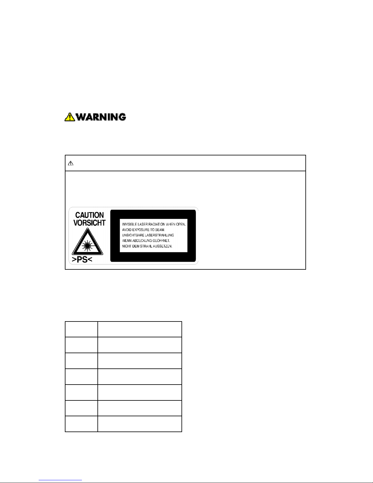
WARNING FOR LASER UNIT
WARNING: Turn off the main switch before attempting any of the procedures in the
Laser Unit section. Laser beams can seriously damage your eyes.
CAUTION MARKING:
Symbols and Abbreviations
Conventions Used in this Manual
This manual uses several symbols.
Symbol What it means
☛
Refer to section number
Screw
Connector
E-ring
Clip ring
Clamp
Page 9
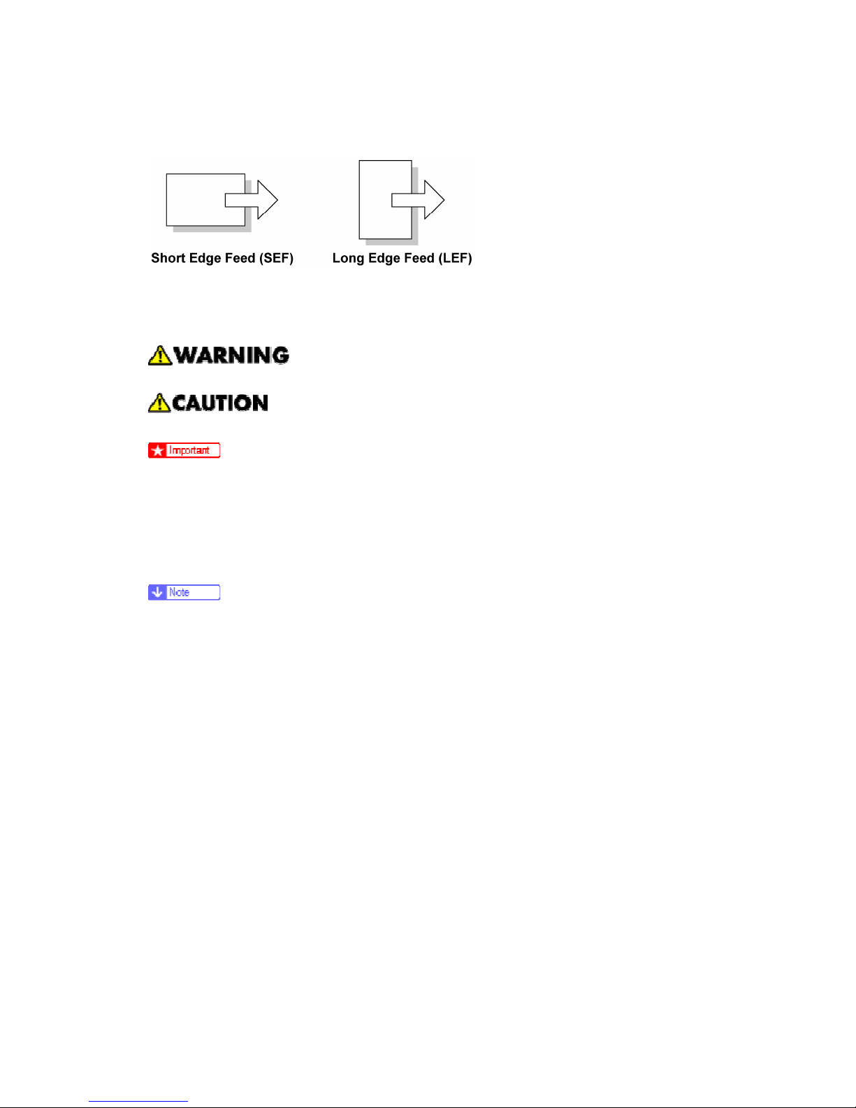
Cautions, Notes, etc.
The following headings provide special information:
Failure to obey warning information could result in serious injury or death.
Obey these guidelines to ensure safe operation and prevent minor injuries.
Obey these guidelines to avoid problems such as misfeeds, damage to originals,
loss of valuable data and to prevent damage to the machine.
Always obey these guidelines to avoid serious problems such as misfeeds,
damage to originals, loss of valuable data and to prevent damage to the machine.
bold is added for emphasis.
This information provides tips and advice about how to best service the machine.
Page 10

Page 11
Controller Box and Printer/Scanner
SM 1 B867
B867
Printer/
Scanner Unit
1. INSTALLATION
1.1 CONTROLLER BOX AND PRINTER/SCANNER
When you install the printer/scanner option, the GW controller box must also be installed.
This procedure shows the installation procedure for the GW controller box and
printer/scanner option.
1.1.1 ACCESSORY CHECK
No. Description Q’ty
1 Installation procedure 1
2 Controller box 1
3 Operation panel 1
4 Expansion decal 1
5 Screw M3 x 8 1
6 Tapping screw M3 x 6 6
7 Ground cable 1
Controller Box
8 Clamp 1
1 Installation procedure 1
2 Dummy cover–fax 1
3 Dummy key top 1
4 Printer/Scanner key panel 2
5 SD card 1
6 RAM DIMM 1
7 Ferrite core 1
8 Operating instructions 1
Printer Scanner
9 FCC label 1
Page 12
Controller Box and Printer/Scanner
B867 2 SM
1.1.2 INSTALLING EXPANSION COMPONENT
Unplug the machine power cord before starting the following procedure.
Step 1–Controller Box
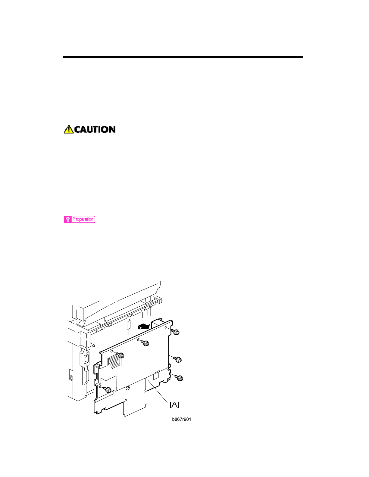
1. Remove the rear cover [A] ( x 6).
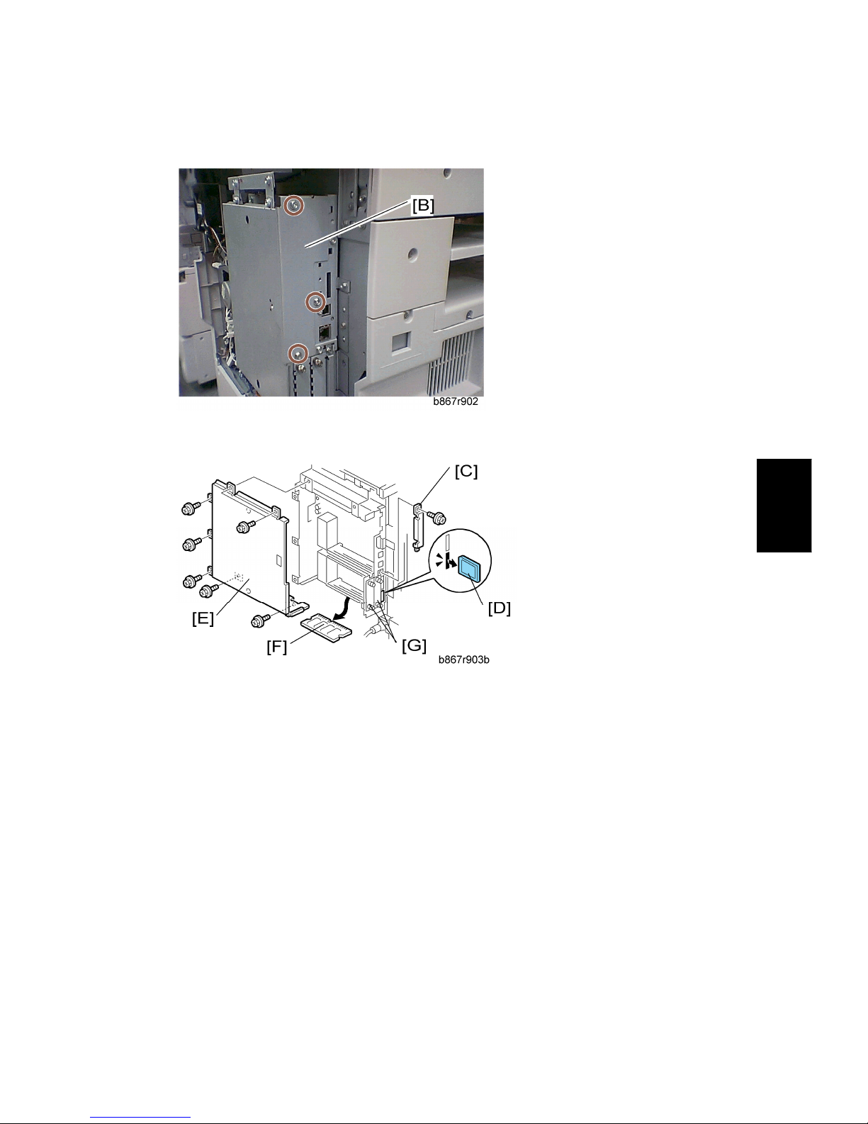
2. Remove the slot cover [B] ( x 1).
3. Remove one screw [C] from the BICU.
Page 13

Controller Box and Printer/Scanner
SM 3 B867
B867
Printer/
Scanner Unit
4. Connect the controller box [E] to the BICU. Make sure that the BICU is not damaged
[F] and that the three openings [G][H][I] hold the controller box.
5. Fasten the screws ( x 7 [including the screw [C]).
6. Remove the FCU cover [J] ( x 3).
Step 2–Printer/Scanner
1. Remove the controller-box cover [A] ( x 7).
2. Install the RAM DIMM [B].
3. Remove the SD-card cover [C]
( x 1).
4. Install the SD card [D] in the lowest slot.
5. Install the SD-card cover.
Page 14
Controller Box and Printer/Scanner
B867 4 SM
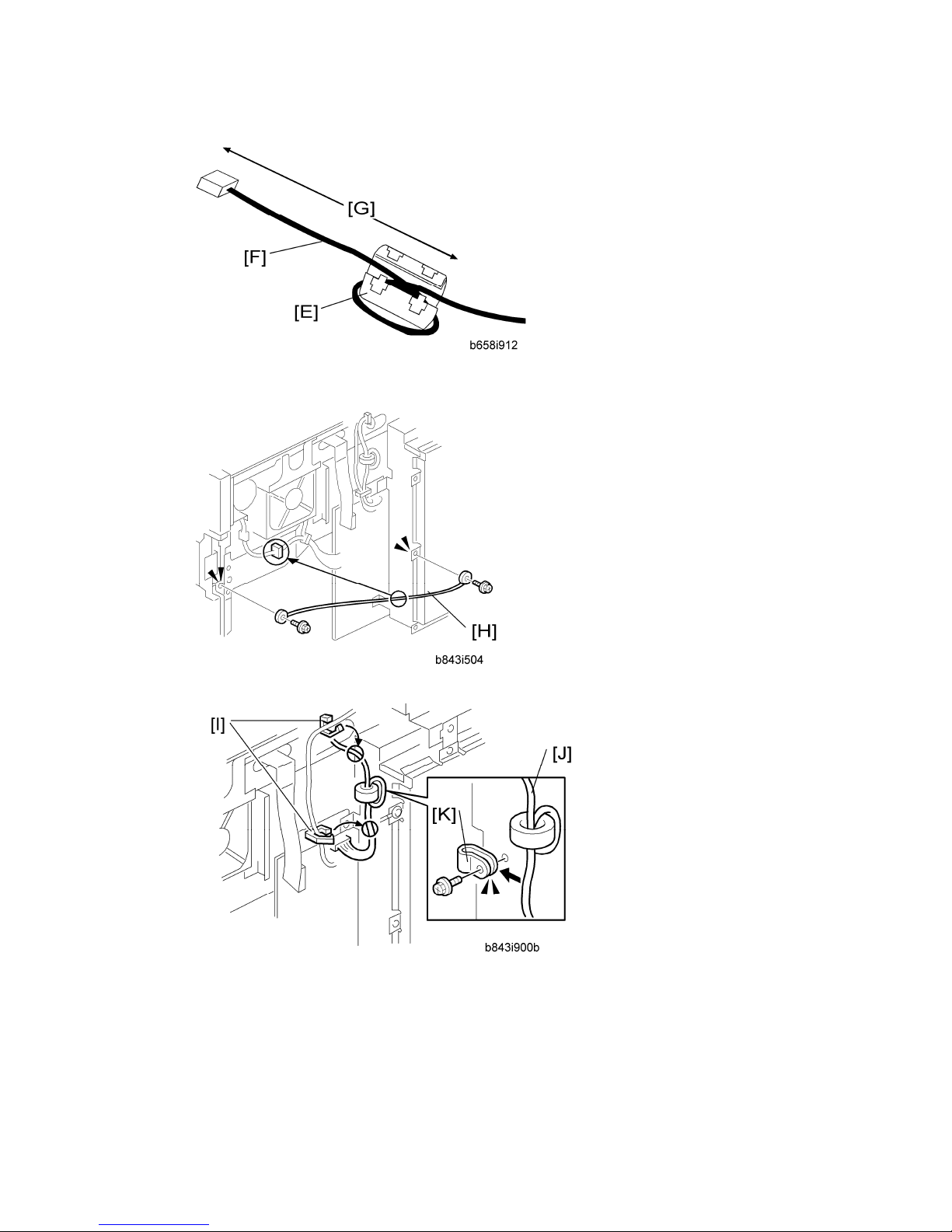
6. Attach the ferrite core [E] to the network cable [F]. The end of the ferrite core must be
about 8 cm (3.2") from the end of the cable [G].
7. Install the ground cable [H] as shown, and then clamp the cable ( x 2, x 1).
8. Release the clamps [I], and then bind the harness [J] with the clamp [K].
9. Attach the clamp [K] to the controller box.
10. If you do not install the FCU, reinstall the FCU bracket (which has been removed in
Step 1 Item 7), to the controller box.
Page 15
Controller Box and Printer/Scanner
SM 5 B867
B867
Printer/
Scanner Unit
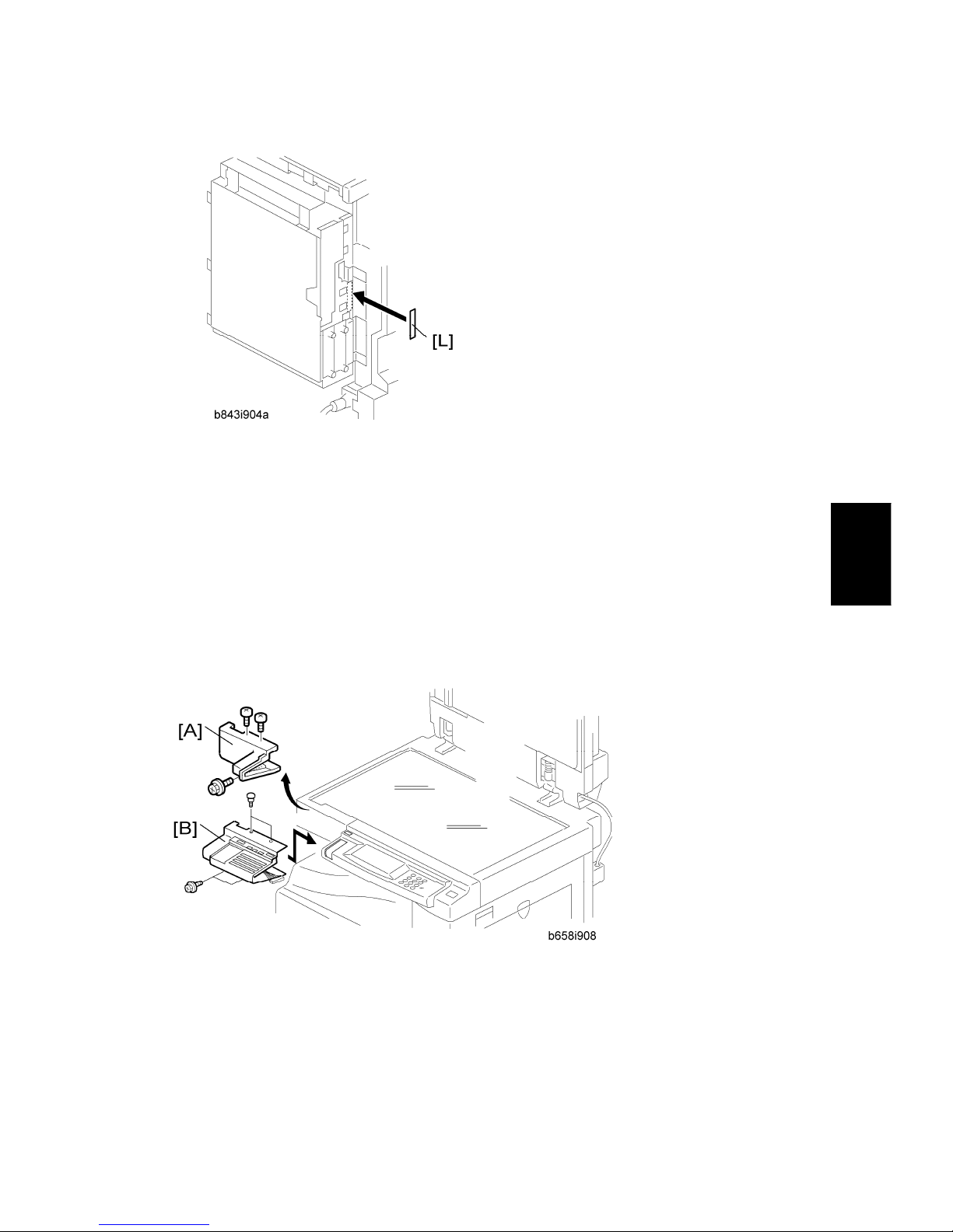
11. Attach the FCC label [L] at the right-hand side of the USB connector on the controller
box (for the USA model only).
If installing fax option go to fax installation step now.
Step 4–Reassembling
1. Reassemble the controller box.
2. Install the rear cover.
1.1.3 INSTALLING PANELS AND KEYS
Step 5–Panel
1. Remove the front upper left cover [A] ( x 3).
2. Install the optional operational panel [B] ( x 1, x 4 [including the three screws
removed in step 1]).
Page 16
Controller Box and Printer/Scanner
B867 6 SM
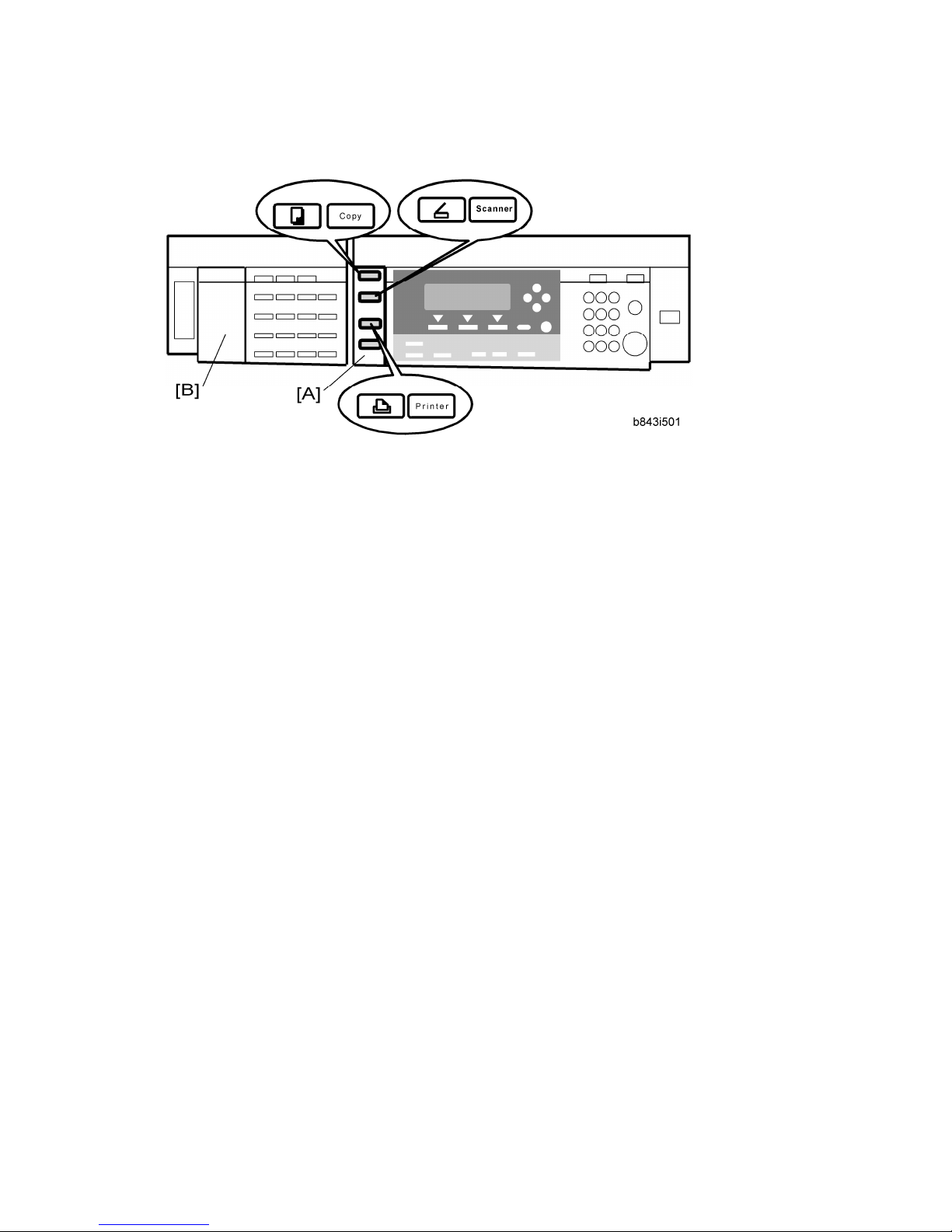
Step 6–Printer/Scanner Keys
1. Remove the dummy cover (from the basic operation panel) and install the
printer/scanner key panel [A].
2. Install the dummy fax cover [B].
1.1.4 SETTINGS
Step 9–Printer/Scanner Model Settings
1. Turn the main switch on.
2. Start the SP mode.
3. Select SP5-985-001 (NIC setting) and change the setting value to "1" (ON).
4. Select SP5-985-002 (USB setting) and change the setting value to "1" (ON).
5. Turn the main switch off and on.
6. Start the SP mode.
7. Select SP5-801-001 and initialize the all SP data.
8. Exit the SP mode, and then start the UP mode.
9. Select the "@Remote Service" ("User Tool" > "System Settings > Administrator Tools"
> "Extended Security" > @Remote Service") and select "Prohibit".
10. Exit the UP mode, and then start the SP mode.
11. Select SP5-870-003 and execute initialization for @Remote.
12. Select SP5-907-001 and specifies the "Plug & Play".
13. Select SP5-870-001 and execute writing certification for @Remote.
14. Select SP5-302-002 and specify the time zone.
15. Select SP5-307-001, 003, and 004 and specify the daylight-saving time settings.
16. Exit the SP mode.
17. Turn the main switch off and on.
18. Start the UP mode.
Page 17

Controller Box and Printer/Scanner
SM 7 B867
B867
Printer/
Scanner Unit
19. Specifies the date and time with "Set Date" or "Set Time" (User Tool" > "System
Settings" > "Set Date" or "Set Time").
Page 18
Controller Options
B867 8 SM
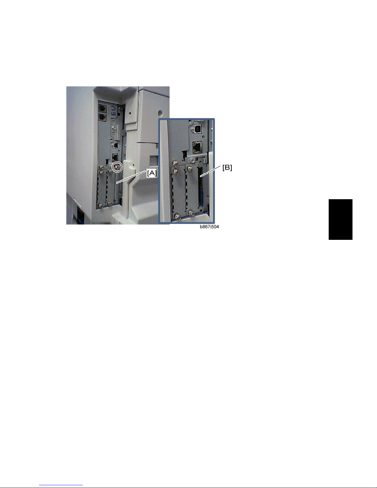
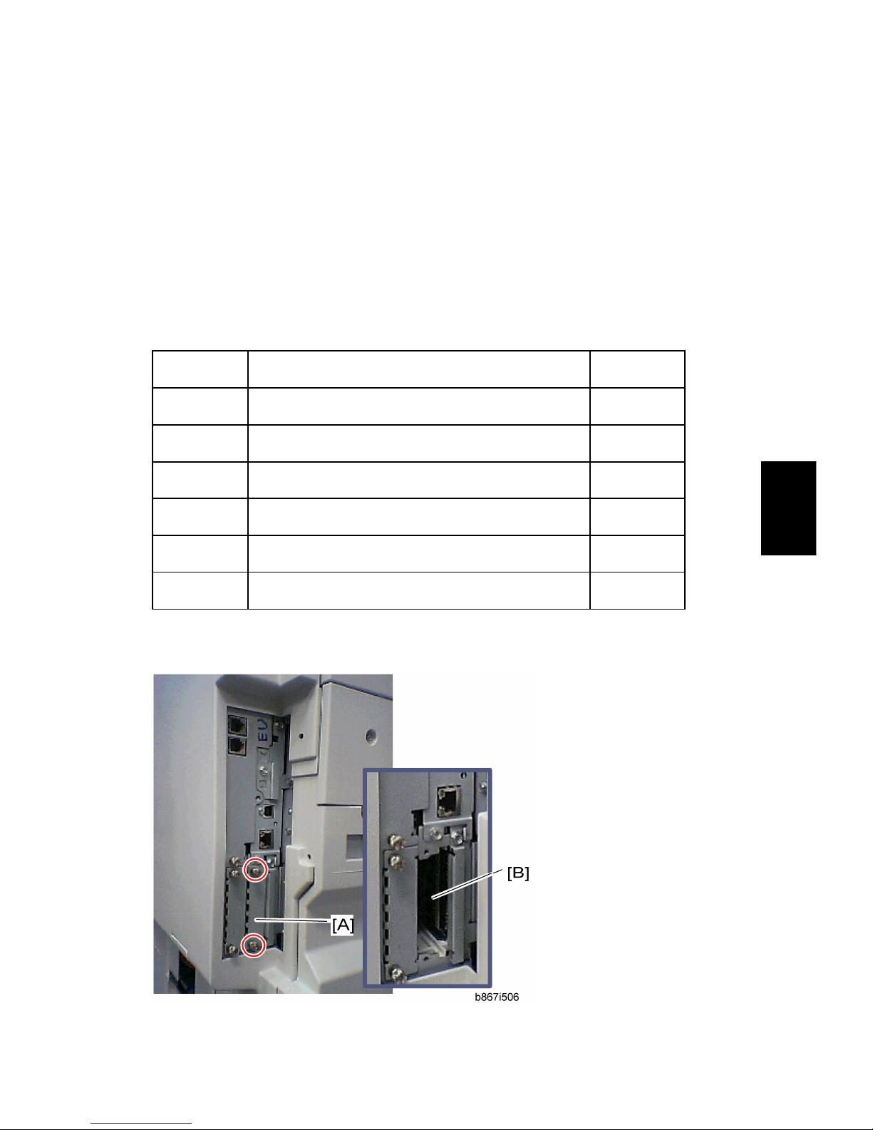
1.2 CONTROLLER OPTIONS
1.2.1 OVERVIEW
This machine has I/F card slots and SD card slots for optional I/F connections and
applications.
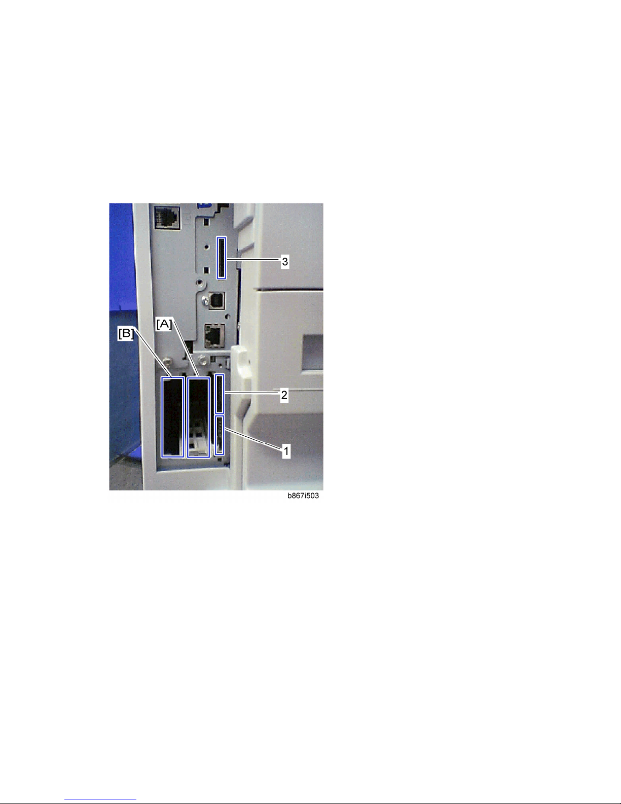
I/F Card Slot
Slot [A] is used for one of the optional I/F connections: (IEEE1284, IEEE802.11
(Wireless LAN), Bluetooth or Embedded RCG-M).
Slot [B] do not use.
SD Card Slot
Slot [1] is used for optional printer/scanner application only.
Slot [2] is used for PostScript3.
Slot [3] is used for the Java VM Option or service use.
Page 19
Controller Options
SM 9 B867
B867
Printer/
Scanner Unit
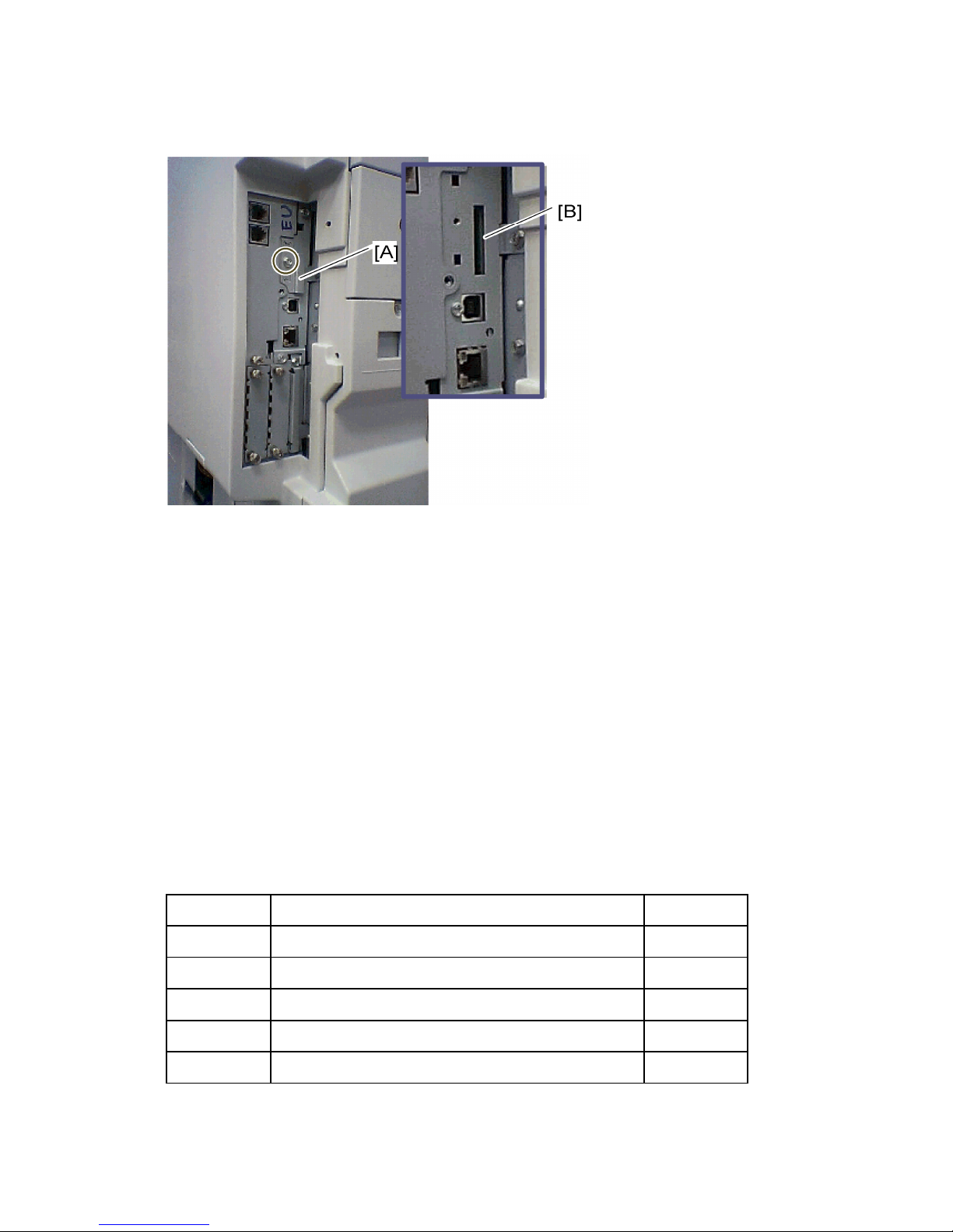
1.2.2 POSTSCRIPT3 INSTALLATION
Installation Procedure
1. Remove the SD card slot cover [A] ( x 1).
2. Install the PostScript3 SD card into the slot 2 [B].
3. Reinstall the SD card slot cover [A] ( x 1).
4. Turn on the main power switch.
5. Print out the configuration page (User Tools/ Counter > Printer Features > List/
Test Print), and then check that this device is detected.
6. Attach the "Adobe PostScript3" decal to the front cover of the machine.
1.2.3 JAVA VM OPTION INSTALLATION
Installation Procedure
⇒
Rev. 11/2008
Page 20
Controller Options
B867 10 SM
1. Remove the slot cover [A] from the SD card slot 3 ( x 1).
2. Turn the SD-card label face to the rear of the machine. Then push it slowly into
slot 3 [B] until you hear a click.
3. Turn ON the main power switch.
NOTE: After you turn ON the main power switch, the Java platform will be
installed automatically.
4. Reattach the slot cover [A] (x 1).
IMPORTANT:
Do not remove the VM option SD card after installation. Keep the SD card in slot 3.
For third vendor Java-based SDK applications, you can remove the SD card after
installation. For the installation procedure, see the vendor’s installation manual.
1.2.4 WIRELESS LAN (IEEE 802.11B) INSTALLATION
Component Check
No. Description Q’ty
1 Wireless Adapter 1
2 Wireless LAN Card 1
3 LAN Card Cover 4
4 Caution Sheet 1
5 Label 1
⇒
Rev. 08/2007
Page 21
Controller Options
SM 11 B867
B867
Printer/
Scanner Unit
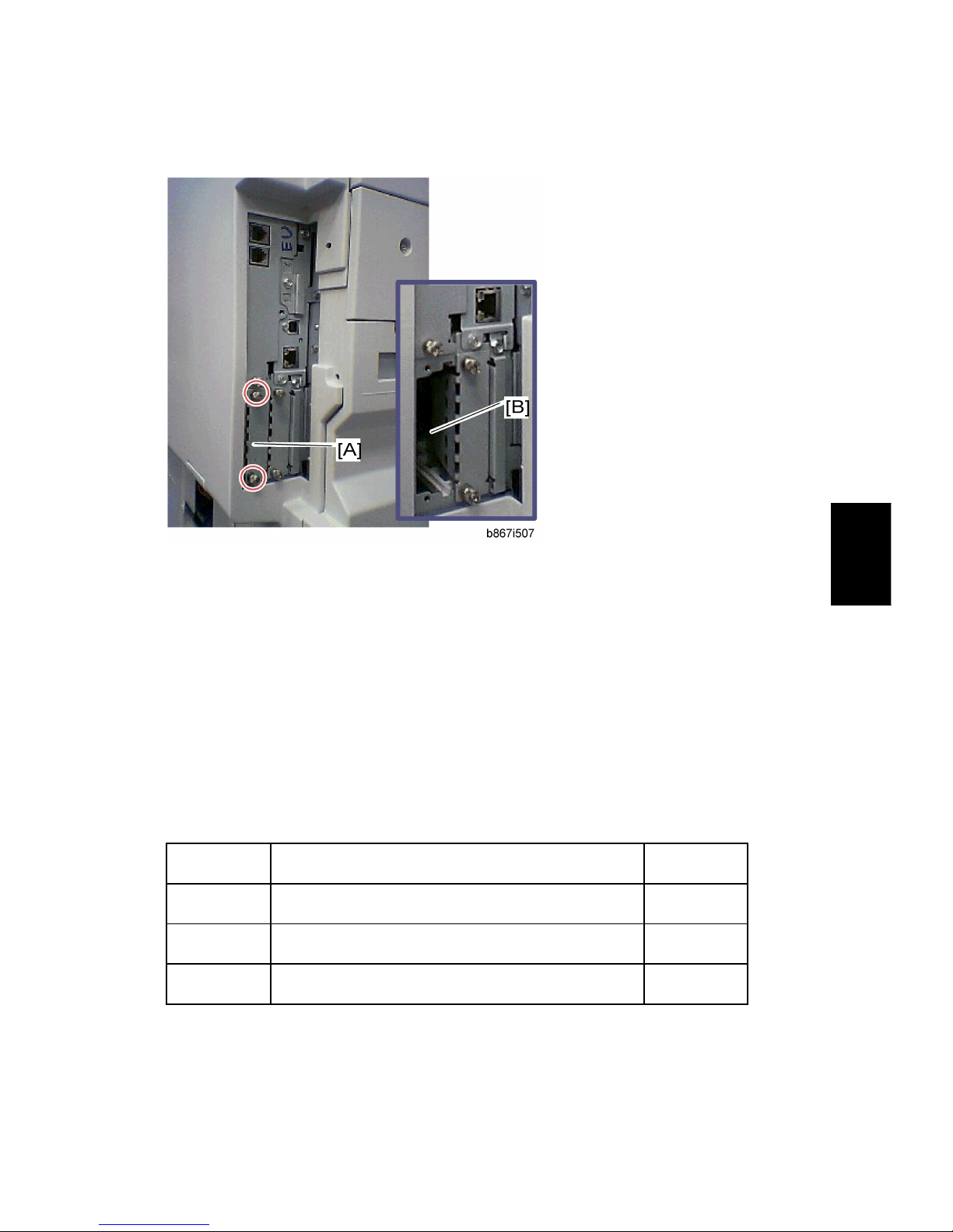
Installation Procedure
1. Remove the interface cover [A] ( x 2).
2. Install the Wireless adaptor to the slot A [B] ( x 2).
3. Install the Wireless LAN card to the wireless adaptor.
4. Attach the antenna cap to the wireless LAN card.
5. Turn on the main power switch.
6. Print out the configuration page (User Tools/Counter > Printer Features >
List/Test Print), and then check that this device is detected.
If reception is poor, you may need to move the machine:
Make sure that the machine is not located near an appliance or any type of equipment
that could generate a strong magnetic field.
Position the machine as close as possible to the access point.
SP Mode Settings for IEEE 802.11b Wireless LAN
The following SP commands can be set for IEEE 802.11b
SP No. Name Function
5840 004 SSID Used to confirm the current SSID setting.
5840 006 Channel MAX
Sets the maximum range of the channel settings for
the country.
Page 22
Controller Options
B867 12 SM
5840 007 Channel MIN
Sets the minimum range of the channel settings
allowed for your country.
5840 011 WEP Key Select Used to select the WEP key (Default: 00).
5840 018 SSID Check Used to check the SSID.
5840 020 WEP Mode
Used to display the maximum length of the string that
can be used for the WEP Key entry.
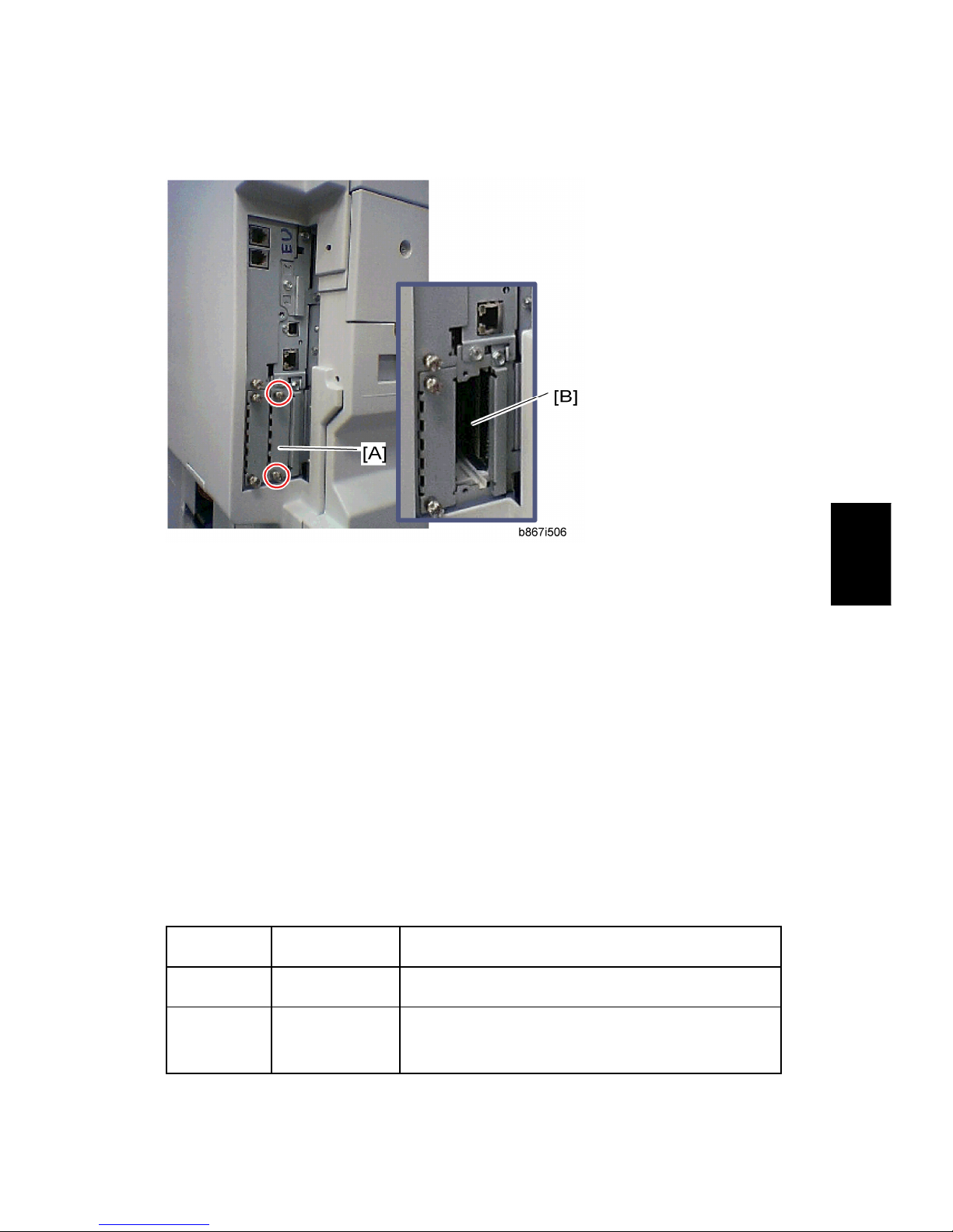
1.2.5 IEEE 1284 INSTALLATION
Component Check
No. Description Q’ty
1 IEEE1284 Interface Ass’y 1
2 UL Sheet 1
3 Caution Sheet 1
Installation Procedure
Page 23
Controller Options
SM 13 B867
B867
Printer/
Scanner Unit
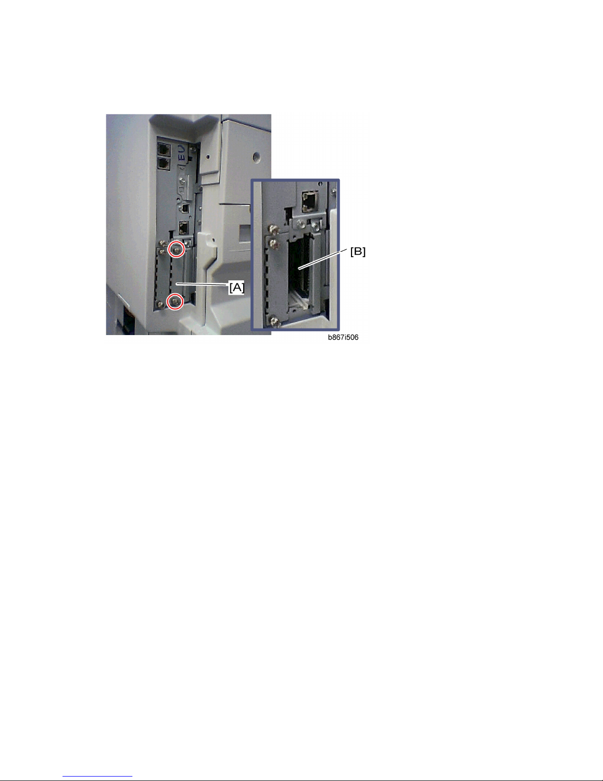
1. Remove the interface cover [A] ( x 2).
2. Install the IEEE 1284 board in interface slot A [B] ( x 2).
3. Turn on the main power switch.
4. Print out the configuration page (User Tools/Counter > Printer Features >
List/Test Print), and then check that this device is detected.
1.2.6 BLUETOOTH INSTALLATION
Component Check
No. Description Q’ty
1 Wireless Adapter 1
2 Bluetooth Card 1
3 Bluetooth Card Adapter 1
4 Bluetooth Card Cover 1
5 UL/FCC Sheet 1
6 Caution Sheet 1
Installation Procedure
Page 24

Controller Options
B867 14 SM
1. Remove the interface cover [A] ( x 2).
2. Install the Wireless adaptor in interface slot A [B] ( x 2).
3. Select an appropriate FCC label from the FCC sheet, and then attach the FCC
label to the non-label side of the Bluetooth card.
4. Install the Bluetooth card in the wireless adaptor.
5. Attach the antenna cap to the Bluetooth card.
6. Turn on the main power switch.
7. Print out the configuration page (User Tools/ Counter > Printer Features > List/
Test Print), and then check that this device is detected.
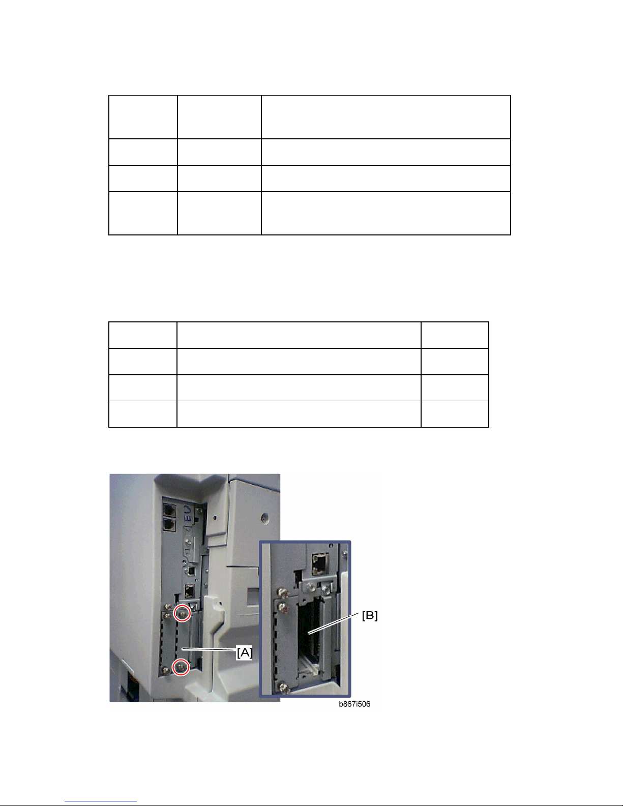
1.2.7 USB HOST INSTALLATION
Component Check
No. Description Q’ty
1 USB Host Interface Ass’y 1
2 USB Cable 1
3 Ferrite Core 1
4 Clamp 1
5 UL Sheet 1
Page 25
Controller Options
SM 15 B867
B867
Printer/
Scanner Unit
Installation Procedure
1. Remove the interface cover [A] ( x 2).
2. Install the USB host board in the interface slot B [B] ( x 2).
3. Turn on the main power switch.
4. Print out the configuration page (User Tools/ Counter > Printer Features > List/
Test Print), and then check that this device is detected.
5. Exit the User Tools mode.
1.2.8 REMOTE COMMUNICATION GATE INSTALLATION
This option requires the printer/scanner application and DIMM 256 MB.
Component Check
No. Description Q’ty
1 Remote Comm. Gate Interface Ass’y 1
2 Cover 1
3 Screw 3
Page 26
Controller Options
B867 16 SM
Installation Procedure
1. Remove the interface cover [A] ( x 2).
2. Install the modem board into interface slot A [B] ( x 2).
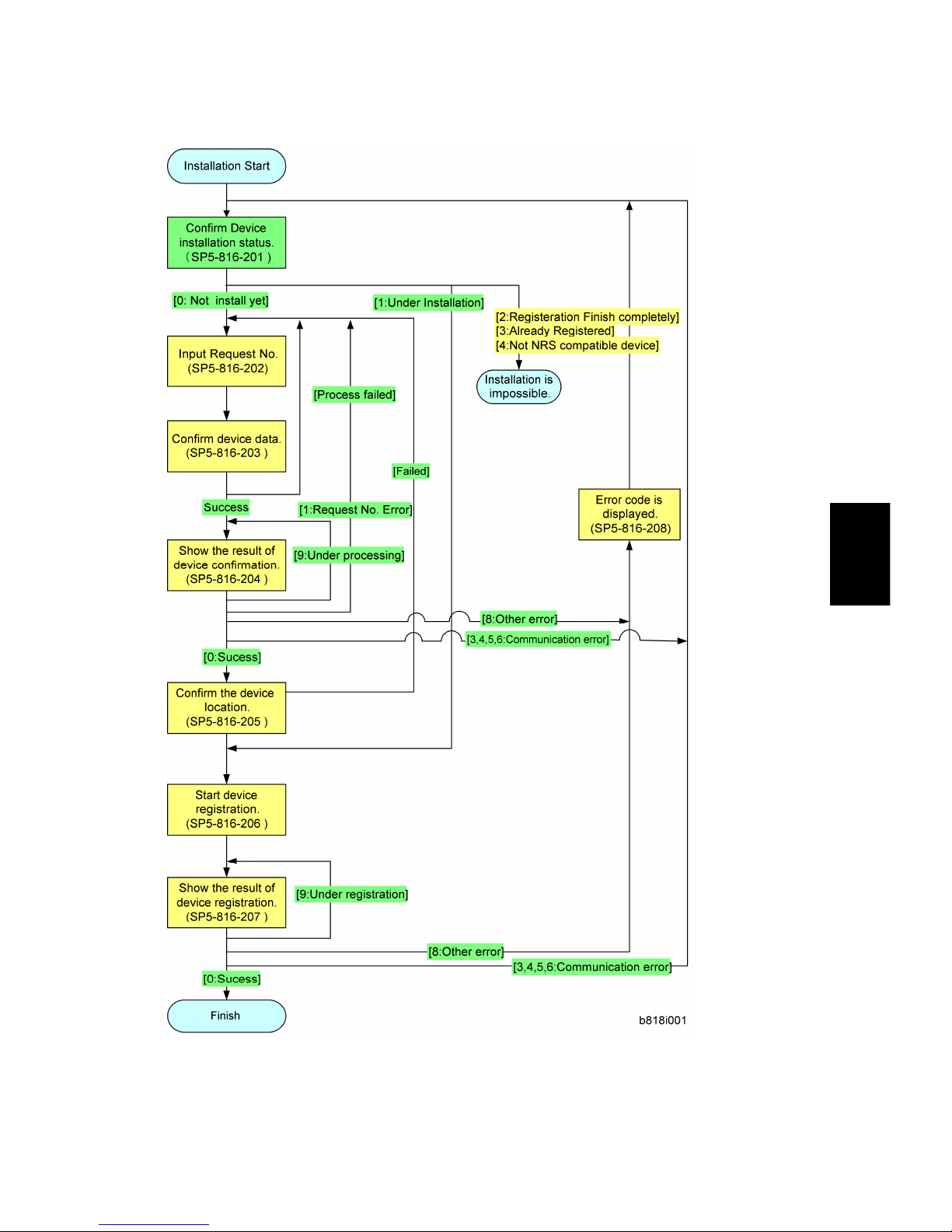
3. Confirm the following SP settings before starting installation flow.
SP5-985-001 ("On Board NIC" is set to "0: OFF".)
SP5-816-150 (To Select the country)
SP5-816-154 (To set an outside connection telephone number)
SP5-816-161 (To set a telephone number)
4. Follow the Installation flow as shown below with SP mode.
Page 27
Controller Options
SM 17 B867
B867
Printer/
Scanner Unit
Page 28
Main Board
B867 18 SM
2. REPLACEMENT AND ADJUSTMENT
2.1 MAIN BOARD
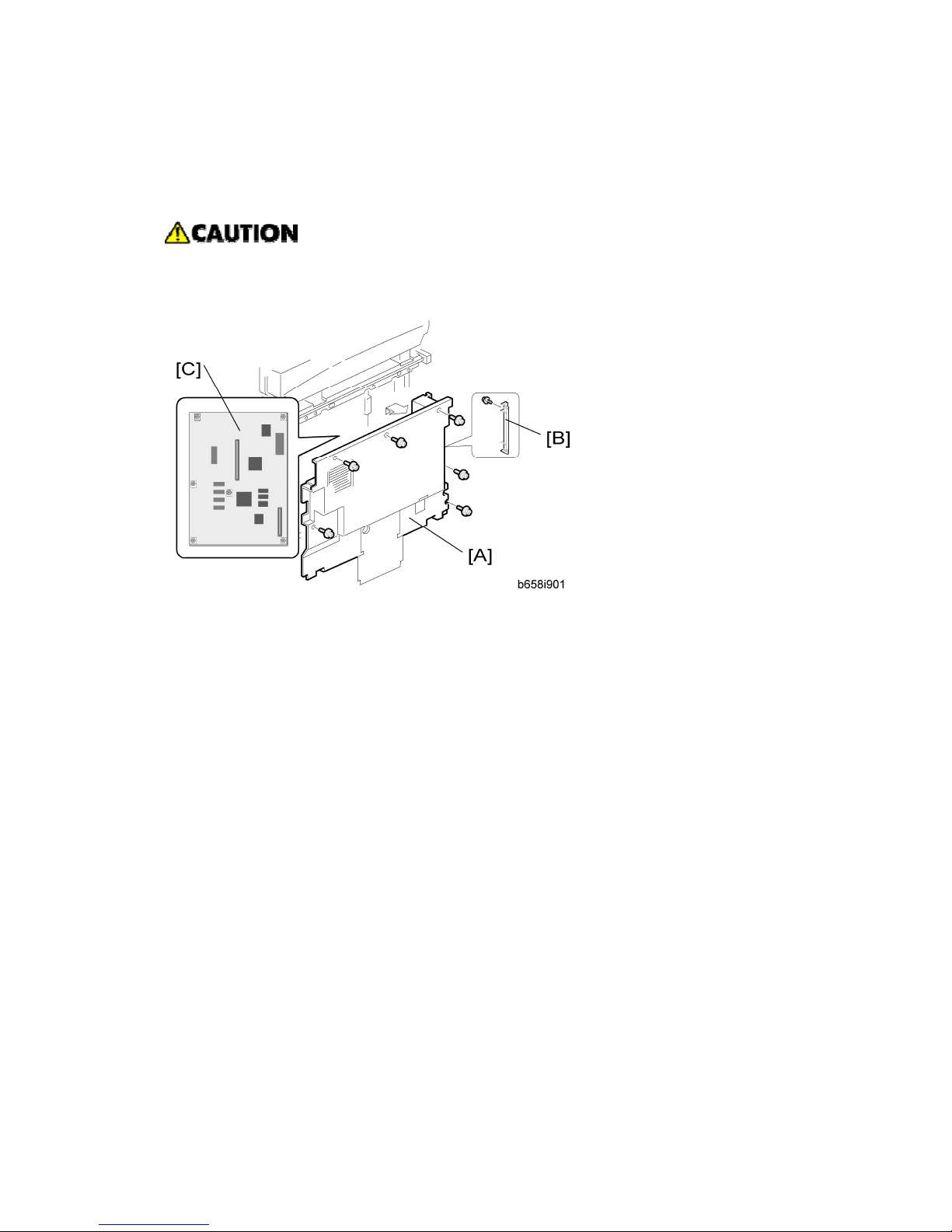
2.1.1 PRECAUTIONS
Turn off the main power switch and unplug the machine before starting
replacement.
Before turning off the main power switch, check that no mechanical component is
operating. Mechanical components may stop out of their home positions if you turn
off the main power switch while they are operating. The component may be
damaged if you try to remove it when it is not in the home position.
2.1.2 CONTROLLER BOARD
Before replacing the controller board, be sure to print out SMC or save the
NVRAM data.
Saving from the Controller NVRAM to an SD card (☛ "NVRAM Data
Upload/Download [SP5-824/825]" in the chapter "Service Tables" of the this
manual)
Page 29
Main Board
SM 19 B867
B867
Printer/
Scanner Unit
1. Remove the rear cover [A] ( x 6)
2. Remove the FCU cover [B] ( x 3).
3. Remove the SD-card cover [C] ( x 1), and then remove all SD cards in the SD slots.
4. Remove the controller-box cover [E] ( x 7).
5. Remove the RAM DIMM [F] if it has been installed.
6. Remove the two I/F covers [G] (or I/F options if they have been installed).
Page 30
Main Board
B867 20 SM
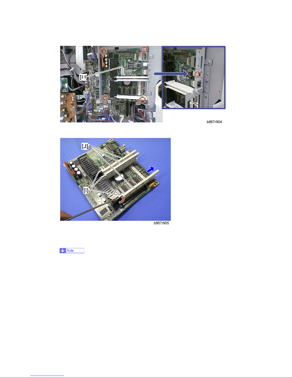
7. Remove the controller board with the rails [H] ( x 5).
8. Release the hooks [I], and then pull out the rails [J].
9. Controller board
When replacing the controller board, remove the NVRAMs from the board.
Install the NVRAMs to the new board.
Page 31

Main Board
SM 21 B867
B867
Printer/
Scanner Unit
When replacing the NVRAM on the controller board
1. When you replace the NVRAMs [A], make sure that the NVRAMs are correctly
installed.
2. The mark [B] on the NVRAM should be directed to the right side (seem from the back
side of the machine).
3. Reassemble the machine.
4. Copy the old NVRAM data to the new NVRAM with SP5-825 or input the SMC data in
the machine. (For details, refer to the "NVRAM Data Upload/Download [SP5-824/825]"
in the chapter "Service Tables" of the this manual)
Page 32

Service Call Conditions
B867 22 SM
3. TROUBLESHOOTING
3.1 SERVICE CALL CONDITIONS
3.1.1 SERVICE CALL CONDITIONS
There are four levels of service call conditions.
Level Definition Reset Procedure
A
To prevent damage to the machine, the main
machine cannot be operated until the SC has
been reset by a service representative (see
the note below).
Enter SP mode, and then turn
the main power switch off and
on.
B
If the SC was caused by incorrect sensor
detection, the SC can be reset by turning the
main power switch off and on.
Turn the main power switch
off and on.
C
The main machine can be operated as usual,
excluding the unit related to the service call.
Turn the main power switch
off and on.
D
The SC history is updated. The machine can
be operated as usual.
The SC will not be displayed.
Only the SC history is
updated.
If the problem concerns electrical circuit boards, first disconnect then reconnect
the connectors before replacing the PCBs.
If the problem concerns a motor lock, first check the mechanical load before
replacing motors or sensors.
Do not try to use the operation panel during an automatic reboot.
If the Remote Service System is used, the SC code is sent immediately to the
Service Center
Page 33

Service Call Conditions
SM 23 B867
B867
Printer/
Scanner Unit
3.1.2 GW SC CODE DESCRIPTIONS
SC6xx
No.
Definition
Symptom Possible Cause/Countermeasure
CSS communication error
630 D
The machine tries to communicate
with one of the terminals of a
relevant service center. → An error
signal returns.
Communication error on the
public telephone network
(logged only; the machine can
still operate)
MF accounting device error 1
632 C
The machine sends a data frame.
→ No normal end signal returns. →
This symptom happens three
times.
Defective or broken line
between machine and device
MF accounting device error 2
633 C
The machine is communicating
with the accounting device. → The
break signal returns.
Defective or broken line
between machine and device
MF accounting device error 3
634 C
A backup RAM error is reported
from the accounting device.
Defective accounting device
controller
Defective battery in the
accounting device
MF accounting device error 4
635 C
A battery voltage error is reported
from the accounting device.
Defective accounting device
controller
Defective battery in the
accounting device
Page 34

Service Call Conditions
B867 24 SM
No.
Definition
Symptom Possible Cause/Countermeasure
636 SD Card Error
Expanded authentication module error
-001 B
There is no expanded
authentication module in the
machine.
The SD card or the file of the
expanded authentication module is
broken.
There is no DESS module in the
machine.
1. Install the correct SD card or the
file of the expanded
authentication module.
2. Install the DESS module.
Version error
-002 B
The version of the expanded
authentication module is not
correct.
1. Install the correct file of the
expanded authentication
module.
650 Communication error of the remote service modem (Embedded RCG-M)
Authentication error
-001 C
The authentication for the
Embedded RCG-M fails at a dial up
connection.
1. Check and set the correct user
name (SP5816-156) and
password (SP5816-157).
Incorrect modem setting
-004 C
Dial up fails due to the incorrect
modem setting.
1. Check and set the correct AT
command (SP5819-160).
Communication line error
-005 C
The supplied voltage is not
sufficient due to the defective
communication line or defective
connection.
1. Consult with the user's local
telephone company.
Page 35

Service Call Conditions
SM 25 B867
B867
Printer/
Scanner Unit
No.
Definition
Symptom Possible Cause/Countermeasure
Incorrect network setting
-011 C
Both the NIC and Embedded
RCG-M are activated at the same
time.
1. Disable the NIC with SP5985-1.
Modem board error
-012 C
The modem board does not work
properly even though the setting of
the modem board is installed with a
dial up connection.
1. Install the modem board.
2. Check and reset the modem
board setting with SP5816.
3. Replace the modem board.
651 Incorrect dial up connection
Program parameter error
-001 D
The unexpected error occurs when
the modem (Embedded RCG-M)
tries to call the center with a dial up
connection.
Software bug.
Program execution error
-002 D
Same as SC651-001. Software bug.
Engine startup error
670 B
Just after the main power is turned
on or the machine is recovering
from auto off mode, the engine
ready signal assertion fails.
Just after the main power is turned
on, the engine does not respond.
Poor connection between the
BICU and controller board
Defective BICU
Defective controller board
Controller-to-operation panel communication error at startup
672 B
After powering on the machine,
communication between the
Controller stalled
Controller board installed
Page 36

Service Call Conditions
B867 26 SM
No.
Definition
Symptom Possible Cause/Countermeasure
controller and operation panel does
not begin, or the communication is
interrupted after a normal startup.
incorrectly
Defective controller board
Operation panel connector loose
or defective
Poor connection of DIMM and
optional boards on the controller
board
1. Check the setting of
SP5875-001. If the setting is set
to "1 (OFF)", change it to "0
(ON)".
SC8xx
No.
Definition
Symptom Possible Cause/Countermeasure
Watchdog error
818 B
While the system program is
running, no other programs can
run (due to a bus hold or endless
loop).
Defective controller board
1. Reinstall the system program.
2. Replace the controller board.
819 Kernel stop
Process error
[0696e] B
System completely down
Defective RAM DIMM
Defective SD card in slot 1
(lowest slot)
Defective controller
Software error
1. Check and/or replace the RAM
Page 37

Service Call Conditions
SM 27 B867
B867
Printer/
Scanner Unit
DIMM.
2. Check and/or replace the SD
card in slot 1 (lowest slot).
3. Replace the controller.
See NOTE at the end of the SC
table.
VM full error
[0766d] B
Unexpected system memory size
Defective RAM DIMM
Defective SD card in slot 1
(lowest slot)
Defective controller
Software error
1. Check and/or replace the RAM
DIMM.
2. Check and/or replace the SD
card in slot 1 (lowest slot).
3. Replace the controller.
See NOTE at the end of the SC
table.
Cache error
[4361] B
Cache error in the CPU
Defective CPU
1. Replace the controller board.
The others
[----] B
Error in OS
Defective memory
Defective flash memory
Defective CPU
1. Replace the controller board.
Self-Diagnostic Error: CPU
820
B [0001-0015] [000A-000D]: Detailed error code
Page 38

Service Call Conditions
B867 28 SM
During the boot monitor program
and self-diagnostic, any
exception or cut-in are not
supposed to happen. If these
happen, it is defined as SC.
Defective CPU device
Defective boot monitor program
or self-diagnostic program
1. Replace the controller board.
2. Reinstall the system firmware.
[00FF]: Detailed error code
B
Cache access error in the CPU
Defective CPU
Defective local bus
1. Turn the main power switch off
and on.
2. Reinstall the system program.
3. Replace the controller board.
[0601, 0602, 0605, 0606, 0607, 0609]: Detailed error code
B
Exceptional command does not
operate even though it is
executed on purpose.
Defective CPU devices
1. Replace the controller board.
[060A-060E]: Detailed error code
B
Cut-in command does not
operate when it is executed.
Defective CPU devices
Defective ASIC devices
1. Replace the controller board.
[0610]: Detailed error code
B
Timer cut-in does not operate
even though it is set.
Defective CPU devices
1. Replace the controller board.
[0612]: Detailed error code
B
Cut-in in ASIC occurs.
Defective ASIC
Defective devices in which ASIC
detects cut-in.
1. Replace the controller board.
B [06FF]: Detailed error code
Page 39

Service Call Conditions
SM 29 B867
B867
Printer/
Scanner Unit
The pipeline clock frequency rate
is different from the prescribed
value.
Defective CPU devices
Mode bit data error, which is
used for initializing CPU.
1. Replace the controller board.
[0702]: Detailed error code
B
The result when the program is
executed in the command cache
is different from desirable value.
Insufficient CPU cache
Insufficient memory process
speed
1. Replace the controller board.
2. Replace the RAM DIMM.
[0709, 070A]: Detailed error code
B
Even you write the data in the
only cache of memory, the data is
actually written in another area
(not cache) of memory.
Defective CPU devices
Incorrect SPD
Boot mode setting error
1. Replace the controller board.
2. Replace the RAM DIMM.
[0801, 0804, 0807, 0808, 0809, 80A]: Detailed error code
B
An error occurs when checking
the TLB.
Defective CPU devices
1. Replace the controller board.
[4002-4005]: Detailed error code
B
The calculation error in the CPU
occurs.
Defective CPU
1. Replace the CPU.
821 Self-Diagnostic Error: ASIC
ASIC error
[0B00] B
The write-&-verify check error
has occurred in the ASIC.
Defective controller board
1. Replace the controller.
ASIC not detected
[0B06] B
The ASIC of the I/O is not
detected.
ASIC (controller board
defective)
Page 40

Service Call Conditions
B867 30 SM
Poor connection between North
Bridge and PCI I/F.
1. Replace controller board.
SHM register check error
[0B10] C
Failed to initialize or could not
read connection bus. Data in
SHM register incorrect.
Defective bus connection
Defective SHM
1. Replace controller board.
Timer error between ASIC and CPU
[0D05] B
The CPU checks if the ASIC
timer works properly compared
with the CPU timer. If the ASIC
timer does not function in the
specified range, this SC code is
displayed.
System firmware problem
Defective RAM-DIMM
Defective controller
Reinstall the controller system
firmware.
1. Replace the RAM-DIMM.
2. Replace the controller board.
823 Self-diagnostic Error: NIB
MAC address check sum error
[6101] C
The result of the MAC address
check sum does not match the
check sum stored in ROM.
Defective controller
1. Replace the controller.
PHY IC error
[6104] C
The PHY IC on the controller
cannot be correctly recognized.
Same as SC823-[6101]
PHY IC loop-back error
[6105] C
An error occurred during the
loop-back test for the PHY IC on
the controller.
Same as SC823-[6101]
Self-diagnostic Error: NVRAM
824 B
The controller cannot recognize NVRAM damaged or abnormal
Page 41

Service Call Conditions
SM 31 B867
B867
Printer/
Scanner Unit
the standard NVRAM installed or
detects that the NVRAM is
defective.
Backup battery has discharged
NVRAM socket damaged
1. Replace the NVRAM.
Self-diagnostic Error: RTC/Optional NVRAM
[1501]: Clock error
B
An RTC device is
recognized, and the
difference between the RTC
device and the CPU exceeds
the defined limit.
No RTC device is
recognized.
RTC defective
NVRAM without RTC installed
Backup battery discharged
1. Replace the NVRAM with
another NVRAM with an RTC
device.
[15FF]: RTC not detected
826
B
The RTC device is not detected.
NVRAM without RTC installed
Backup battery discharged
1. Replace the NVRAM with
another NVRAM with an RTC
device.
827 Self-diagnostic Error: RAM
Verification error
[0201] B
Error is detected during a
write/verify check for the
standard RAM (SDRAM DIMM).
Loose connection
Defective SDRAM DIMM
Defective controller
1. Replace the SDRAM DIMM.
2. Replace the controller.
Resident memory error
[0202] B
The SPD values in all RAM
DIMM are incorrect or
unreadable.
Defective RAM DIMM
Defective SPD ROM on RAM
DIMM
Defective 12C bus
Page 42

Service Call Conditions
B867 32 SM
1. Replace the RAM DIMM.
828 Self-diagnostic Error: ROM
Boost lap code error
[0101] B
The boot monitor and OS
program stored in the ROM
DIMM is checked. If the check
sum of the program is incorrect,
this SC code is displayed.
Defective ROM DIMM
Defective controller
1. Replace the ROM DIMM.
2. Replace the controller.
ROMFS error
[0104] B
All areas of the ROM DIMM are
checked. If the check sum of all
programs stored in the ROM
DIMM is incorrect, this SC code
is displayed.
Defective ROM DIMM
1. Replace the ROM DIMM.
829 Self-diagnostic Error: Optional RAM
Verification error (Slot 1)
[0401] C
The data stored in the RAM in
Slot 1 does not match the data
when reading.
Not specified RAM DIMM
installed
Defective RAM DIMM
1. Replace the RAM DIMM.
2. Replace the controller board.
Composition error (Slot 1)
[0402] C
The result of checking the
composition data of the RAM in
Slot 1 on the controller is
incorrect.
Not specified RAM DIMM
installed
Defective RAM DIMM
1. Replace the RAM DIMM.
2. Replace the controller board.
Self-diagnostic Error: Clock Generator
838 B
A verify error occurred when Defective clock generator
Page 43

Service Call Conditions
SM 33 B867
B867
Printer/
Scanner Unit
setting data was read from the
clock generator via the I2C bus.
Defective I2C bus
Defective I2C port on the CPU
1. Replace the controller board.
IEEE1394 I/F abnormal
851 C
The IEEE1394 interface cannot
be used, due to a driver error.
IEEE1394 interface board
defective
Defective controller board
Wireless card startup error
853 C
The machine starts up. → The
IEEE802 11b card connection
board is recognized. → The
wireless LAN card or bluetooth
card is not recognized.
Loose connection between the
wireless card and the
connection board
Wireless card access error
854 C
The machine has been reading
the data from the card. → The
machine loses access to the
card; the wireless LAN card or
bluetooth card connection board
is still recognized.
Loose connection between the
wireless card and the
connection board
Wireless card error
855 C
Some illegal data is found in the
card.
Defective wireless card
Wireless card connection board error
856 C
An error is detected in the
wireless LAN card or bluetooth
card connection board.
Defective wireless card
connection board
USB I/F Error
857 C
USB interface error is detected. Defective controller
Page 44

Service Call Conditions
B867 34 SM
1. Check the USB connections,
and make sure that they are
securely connected.
2. Replace the controller board.
SD card authentication error
866 C
A digital license error of an SD
card application is detected.
SD card data has corrupted.
1. Store correct data in the SD
card.
SD card error
867 B
An application SD card is
removed from the boot slot while
an application is activated.
An application SD card is
ejected.
SD card access error
(-13 to -3: File system error, other number: Device error)
868 B
An error report is sent from the
SD card reader.
SD card not inserted correctly
SD card defective
Controller board defective
1. For a file system error, format
the SD card on PC.
2. For a device error, turn the main
switch off and on.
3. Remove and re-install the SD
card.
4. Replace the SD card.
5. Replace the controller.
Delete All error 2: Data area
875 B
An error is detected while the all
data of the HDD or NVRAM are
formatted logically by the Data
Overwrite Security Unit (B735).
The logical format for HDD fails.
1. Turn the main switch off/on and
try the operation again.
880 B File Format Converter (MLB) error
Page 45

Service Call Conditions
SM 35 B867
B867
Printer/
Scanner Unit
A request to get access to the
MLB was not answered within
the specified time.
MLB defective
SC9xx
Electronic total counter error
900 B
The value of the total counter is
out of the normal range.
Defective NVRAM
Printer error
920 C
An application error that stops the
machine operation is detected.
Defective software
1. Unexpected hardware resource
(e.g., memory shortage)
Printer font error
921 C
A necessary font is not found in
the SD card when the printer
application starts.
A necessary font is not found in
the SD card.
The SD card data is corrupted.
1. Check that the SD card stores
correct data.
Software performance error
990 B
The software attempted to
perform an unexpected
operation.
NOTE: When this error occurs,
the file name, address, and data
will be stored in NVRAM. This
information can be checked by
using SP7-403. See the data and
the situation in which this SC
occurs. Then report the data and
conditions to your technical
control center.
Software defective
Internal parameter incorrect
Insufficient working memory
991 D Software continuity error
Page 46

Service Call Conditions
B867 36 SM
The software attempted to
perform an unexpected
operation. However, unlike
SC990, the process can keep on
running.
Logged only; the machine can
continue to operate
Undefined error
992 B
An error not controlled by the
system occurred (the error does
not come under any other SC
code).
Defective software program
Application function selection error
997 C
The application selected by a key
press on the operation panel
does not start or ends
abnormally.
Software for that application is
defective
An option required by the
application (RAM, DIMM, board)
is not installed.
Too complicated nest of the fax
group address
1. As for the fax operation problem,
simplify the nest of the fax group
address.
Application start error
998 B
After switching the machine on,
the application does not start
within 60 s. (No applications start
or end normally.)
Software for that application is
defective
An option required by the
application (RAM, DIMM, board)
is not installed.
1. Check the setting of
SP5875-001. If the setting is set
to "1 (OFF)", change it to "0
(OFF)".
Page 47

Service Program Mode
SM 37 B867
B867
Printer/
Scanner Unit
4. SERVICE TABLES
4.1 SERVICE PROGRAM MODE
Before accessing the service menu, do the following:
Confirm that there is no print data in the printer buffer (the ‘Data In’ LED must not
be lit or blinking).
If there is some data in the buffer, wait until all data has been printed.
The main power LED () lights or flashes while the platen cover or ARDF is
open; while the main unit is communicating with a facsimile or the network server;
or while the machine is accessing the memory for reading or writing data.
4.1.1 ENABLING AND DISABLING SERVICE PROGRAM MODE
Entering the SP Mode
1.
Press the Clear Mode key.
2.
Use the keypad to enter “107”.
3.
Hold down Clear/Stop for at least 3 seconds.
4. Enter the Service Mode.
Printer SP
Scanner SP
Select “Printer SP” to enter printer SP mode.
Select “Scanner SP” to enter scanner SP mode.
Exiting the Service Mode
Press the cancel key to exit from the service mode.
Page 48

SP Mode Tables
B867 38 SM
4.2 SP MODE TABLES
The tables in this section list the service programs (SPs).
The following codes are used:
Asterisk (*): The settings are saved in the NVRAM. Most of them return to the default
values when you execute SP 5801 2.
CTL indicates that the data is contained in the NVRAM on the controller board.
The DFU menu is for design or factory use only. You must not change the settings.
Brackets ([ ]): The brackets enclose the setting rage, default value, and minimum step
(with unit) as follows: [Minimum to Maximum / Default / Step].
SSP: Consult your supervisor before you use this program.
4.2.1 SP4-XXX (MODE)
4921* [Image Adj Selection]
Copy [0 to 10 / 0 / 1]
001
Selects which mode the settings from SP4-922 to SP4-932 are used for.
0 = None, 1 = Text 1, 2 =Text 2, 3= Photo 1, 4 = Photo 2, 5 = Photo 3, 6 =
Special 1, 7 = Special 2, 8 = Special 3, 9 = Special 4,
10 = Special 5
Fax [0 to 5 / 0 / 1]
002
Selects which mode the settings from SP4-922 to SP4-932 are used for.
0 = None, 1 = Text 1, 2 = Text 2, 3 = Photo 1, 4 = Photo 2,
5 = Special 1
Scanner [0 to 4 / 0 / 1]
003
Selects which mode the settings from SP4-922 to SP4-932 are used for.
0 = None, 1 = Text 1, 2 = Text 2, 3= Photo 1, 4 = Photo 2
[Scanner Gamma]
4922*
Selects “text” or “photo” as the priority output mode. This setting is applied to
all image processing modes of SP4-921.
Page 49

SP Mode Tables
SM 39 B867
B867
Printer/
Scanner Unit
001 Copy
002 Fax
003 Scanner
[0=System default/ 1=Text/ 2=Photo]
[Notch Selection]
4923*
Selects the value of the center ID adjustment notch for the ID adjustment
LEDs.
Normally the center notch is 3 (range 1-5). If –1 is selected, each notch
shifts down (becomes lighter). If +1 is selected, each notch shifts up
(becomes darker).
This setting is applied to all image processing modes of SP4-921.
001 Copy
002 Fax
003 Scanner
[–1 = Light / 0 = Normal / +1 = Dark]
[Texture Removal]
4926*
Adjusts the texture removal level that is used with error diffusion. 0: The
default value for each mode is used. Text 1, Photo 2, Special 2, and Special 5
have a default of 3 and Photo 1-3 have a default of 1.
1: No removal applied.
2 to 5: Removal applied at the level specified here. The higher the setting
(level), the less clear the image will become (more texture removal). This
setting is only applied to the originals in SP4-921.
001 Copy
002 Fax
003 Scanner
[0 to 6 / 0 / 1/step]
4927* [Line Width Correction]
Page 50

SP Mode Tables
B867 40 SM
Adjusts the line width correction algorithm. Positive settings produce thicker
lines; negative settings produce thinner lines. This setting is only applied to
the originals in SP4-921.
001 Copy
002 Fax
003 Scanner
[–2 to 2 / 0 / 1/step]
[Independent Dot Erase]
4928*
Selects the dot erase level. Higher settings provide greater erasure. This
setting is only applied to the originals in SP4-921.
001 Copy
002 Fax
003 Scanner
[–2 to 2 / 0 / 1/step]
[Positive/Negative] [0 = No, 1 = Yes]
4929*
Inverts white and black. This setting is only applied to the originals in
SP4-921.
001 Copy
002 Fax
[Sharpness-Edge] [–2 to 2 / 0 / 1/step]
4930*
Adjust the clarity. This setting is only applied to the originals in SP4-921.
001 Copy
002 Fax
003 Scanner
Page 51

SP Mode Tables
SM 41 B867
B867
Printer/
Scanner Unit
[Sharpness-Solid] [–2 to 2 / 0 / 1/step]
4931*
Adjust the clarity. This setting is only applied to the originals in SP4-921.
001 Copy
002 Fax
003 Scanner
[Sharpness-Low ID] [–2 to 2 / 0 / 1/step]
4932*
Adjust the clarity. This setting is only applied to the originals in SP4-921.
001 Copy
002 Fax
003 Scanner
4.2.2 SP5-XXX (MODE)
5001 [All Indicators On]
001 All LEDs turn on. The LCDs turn on or off with "ON" or "OFF" key.
5024* [mm/inch Selection]
001
Selects whether mm or inches are used in the display.
After selecting the number, you must turn the main power switch off
and on.
Europe/Asia model: [0: mm / 1: inch]
American model: [0: mm / 1: inch]
5045 [Display-Counter]
Page 52

SP Mode Tables
B867 42 SM
001
Selects the counting display if the meter charge mode is enabled with
SP5-930-001.
You can change the setting only one time.
[0 to 2/ 0 / 1 /step]
0: 1 counter (Total)
1: 2 counters (Total and Prints)
2: 2 counters GPC
[Refill Toner Displ] Refill Toner Detection Display
5051
Enables or disables the toner refill detection display.
001 Refill Toner CTL
[ 0 or 1 / 0 /- ]
0: ON, 1: OFF
5055 [Display IP address]
001 Display IP address CTL
Displays or does not display the IP address
on the LCD.
[0 or 1 / 0 / -]
0: No, 1: Yess
5056 [Coverage Counter]
001 Coverage Counter CTL
Displays or does not display the coverage
counter on the LCD.
[0 or 1 / 0 / -]
0: Not display, 1: Display
[A3 Double Count] SSP
5104*
A3 Double Count CTL [0 = No / 1 = Yes / 2 = No Unclear]
001
Selects whether the machine counts twice for each sheet of A3/11"x 17". If this
is set to “Yes”, the total (mechanical) counter and the current user counter will
Page 53

SP Mode Tables
SM 43 B867
B867
Printer/
Scanner Unit
both increment by two for each A3/11" x 17" sheet.
5112 [Non-Std. Paper Set] Non-Standard Paper Set
001
Determines whether a non-standard paper size can be input for the universal
cassette trays (Tray 2, Tray 3)
[0 or 1 / 0 / - ]
0: No
1: Yes. If “1” is selected, the customer will be able to input a non-standard
paper size using the UP mode.
5113 [Optional Counter Type]
001 Optional Counter Type 1 CTL
This program specifies the counter type.
0: None
1: Key card (RK 3, 4)
2: Key card (down)
3 to 10: Japan only
11: Exp. key card (Add)
12: Exp. key card (Deduct)
002 Optional Counter Type 2 CTL
This program specifies the external
counter type.
0: None
1: Expansion device 1
2: Expansion device 2
3: Expansion device 3
5114 [MF Key Card Ext.] CTL
[0: Not installed/ 1: Installed (scanning
accounting)]
001 Japan use
5118 [Disable Copying] CTL [0: Not disabled/ 1: Disabled]
Page 54

SP Mode Tables
B867 44 SM
001 This program disables copying.
5120* [Clr For Cnt Remove]
CTL [0=Yes / 1=Standby only / 2=No]
001
Determines under which conditions the copy job settings are reset when the
key counter is removed. With 0, the settings are cleared if the counter is
removed at the end of a job or midway through a job. With 1, they are only
cleared if the counter is removed at the end of a job. With 2, they are not
cleared at all, under either condition. With duplex copies, the job settings are
always preserved, regardless of the setting of this SP mode.
5121* [Counter Up Timing] CTL [0 = Feed In / 1 = Exit]
001
Selects whether the key counter increments at time of paper feed-in or at time
of paper exit.
5127 [APS Mode] CTL [0: Not disabled/ 1: Disabled]
001 This program disables the APS.
5150 [By-pass Long Paper] CTL [0 = Feed In / 1 = Exit]
001
Determines whether the transfer sheet from the by-pass tray is used or not.
Normally the paper length for sub scanning paper from the by-pass tray is
limited to 600 mm, but this can be extended with this SP to 1260 mm.
[Fax Printing Cnt Off]
5167
Enables or disables the automatic print out without an accounting device. This
SP is used when the receiving fax is accounted by an external accounting
device.
001
Fax Printing Counter
Off
CTL
[ 0 or 1 / 0 / – ]
0: Automatic printing
1: No automatic printing
Page 55

SP Mode Tables
SM 45 B867
B867
Printer/
Scanner Unit
[CE Login]
5169
If you change the printer bit switches, you must ‘log in’ to service mode with
this SP before you go into the printer SP mode.
001 CE Login CTL
[0 or 1 / 0 / - ]
0: Disabled
1: Enabled
5188 [Copy NV Version]
001 Copy NV Version CTL
Displays the NVRAM version in the
controller board.
[Set Time]
5302
Adjusts the RTC (real time clock) time setting for the local time zone.
Examples: For Japan (+9 GMT), enter 540 (9 hours x 60 min.)
DOM: +540 (Tokyo)
NA :-300 (New York)
EU :+ 60 (Paris)
CH :+480 (Peking)
TW :+480 (Taipei)
AS :+480 (Hong Kong)
002 Time Difference
CTL
#
[-1440 to 1440 / Area / 1 min./step ]
5307 [Summer Time]
ON/OFF -
[ 0 or 1 / NA, EU, ASIA / 1 /step]
0: Disabled
1: Enabled
NA and EUR: 1, ASIA: 0
001
Enables or disables the summer time mode.
Page 56

SP Mode Tables
B867 46 SM
Make sure that both SP5-307-3 and -4 are correctly set. Otherwise,
this SP is not activated even if this SP is set to "1".
Start - -
003
Specifies the start setting for the summer time mode.
There are 8 digits in this SP. For months 1 to 9, the "0" cannot be input in the
first digit, so the eight-digit setting for -2 or -3 becomes a seven-digit setting.
1st and 2nd digits: The month. [1 to 12]
3rd digit: The week of the month. [1 to 5]
4th digit: The day of the week. [0 to 6 = Sunday to Saturday]
5th and 6th digits: The hour. [00 to 23]
7th digit: The length of the advanced time. [0 to 9 / 1 hour /step]
8th digit: The length of the advanced time. [0 to 5 / 10 minutes /step]
For example: 3500010 (EU default)
The timer is advanced by 1 hour at am 0:00 on the 5th Sunday in March
The digits are counted from the left.
Make sure that SP5-307-1 is set to "1".
End - -
004
Specifies the end setting for the summer time mode.
There are 8 digits in this SP.
1st and 2nd digits: The month. [1 to 12]
3rd digit: The week of the month. [0 to 5]
4th digit: The day of the week. [0 to 6 = Sunday to Saturday]
5th and 6th digits: The hour. [00 to 23]
The 7th and 8th digits must be set to "00".
The digits are counted from the left.
Make sure that SP5-307-1 is set to "1".
[Access Control]
5401
When installing the SDK application, SAS (VAS) adjusts the following
settings. DFU
006 C CTL SSP: These SPs are not disclosed due to the security
Page 57

SP Mode Tables
SM 47 B867
B867
Printer/
Scanner Unit
016 DS CTL
026 F CTL
036 S CTL
046 P CTL
076 SDK 1 CTL
086 SDK 2 CTL
096 SDK 3 CTL
protection.
200
SDK1
Unique ID
CTL
This ID is overwritten by SAS (VAS) when you install or
uninstall the SDK application.
201
SDK1
Certification
Method
CTL [ 0 to 255 / 0 / 1 /step] DFU
210
SDK2
Unique ID
CTL DFU
211
SDK2
Certification
Method
CTL [ 0 to 255 / 0 / 1 /step] DFU
220
SDK3
Unique ID
CTL DFU
221
SDK3
Certification
Method
CTL [ 0 to 255 / 0 / 1 /step] DFU
5404 [User Code Clear]
001
Clears the counts for the user codes assigned by the key operator to restrict
the use of the machine. Press [Execute] to clear.
Page 58

SP Mode Tables
B867 48 SM
5501 [PM Alarm Interval] CTL -
001 Printout
[ 0 to 9999 / 0 / 1 /step]
0: Alarm off
1 to 9999: Alarm goes off when the PM counter
reaches the specified value (1 to 9999) x 1000.
002 ADF
[ 0 or 1 / 1 / – ]
0: No alarm sounds
1: Alarm sounds after the number of originals passing
through the A(R)DF ≥ 10,000
5504 [Jam Alarm] CTL -
001
Sets the alarm to sound for the specified jam level (document misfeeds are
not included).
[ 0 to 3 / 3 / 1 /step]
0: Zero (Off), 1: Low (2.5K jams), 2: Medium (3K jams), 3: High (6K jams)
5505* [Error Alarm]
001
Sets the error alarm level.
The error alarm counter counts "1" when any SC is detected. However, the
error alarm counter decreases by "1" when any SC is not detected during
specified sheets of copies (for example, default 1500 sheets).
The error alarm occurs when the SC error alarm counter reaches "5".
[0 to 255 / 15 / 100 copies per step]
5507 [Supply Alarm] CTL -
001 Paper Size 0: Off, 1: On,
003 Toner 0: Off, 1: On,
128 Interval :Others
132 Interval :A3
[250 to 10000 / 1000 / 1 /step]
Page 59

SP Mode Tables
SM 49 B867
B867
Printer/
Scanner Unit
133 Interval :A4
134 Interval :A5
141 Interval :B4
142 Interval :B5
160 Interval :DLT
164 Interval :LG
166 Interval :LT
172 Interval :HLT
5508* [Auto Call Setting] CTL
-
Jam Remains 0: Disable, 1: Enable
001*
Enables/disables initiating a call for an unattended paper jam.
Frequent Jams 0: Disable, 1: Enable
002*
Enables/disables initiating a call for consecutive paper jams.
Door Open 0: Disable, 1: Enable
003*
Enables/disables initiating a call when the front door remains open.
Jam Remains: Time [ 03 to 30 / 10 / 1 minute /step]
011*
Sets the time a jam must remain before it becomes an “unattended paper
jam”. This setting is enabled only when SP5508 004 is set to 1.
Freq Jam: # of Time [ 02 to 10 / 5 / 1 /step]
012*
Sets the number of consecutive paper jams required to initiate a call. This
setting is enabled only when SP5508 004 is set to 1.
Door Open: Time [ 03 to 30 / 10 / 1 minute/step]
013*
Sets the length of time the door remains open before the machine initiates a
call.
Page 60

SP Mode Tables
B867 50 SM
This setting is enabled only when SP5508 004 is set to 1.
Jam Remains: Mode
0: Automatic Call
1: Audible Warning at Machine
021*
Determines what happens when a paper jam is left unattended.
Freq Jam: Mode
0: Automatic Call
1: Audible Warning at Machine
022*
Determines what happens when a paper jam happens continually.
Door Open: Mode 0: OFF, 1: ON
023*
Determines what happens if the door remains open (15 min.).
Displays a warning if set to ON. Pressing the call button will contact the
service center.
[SC/Alarm Setting] CTL -
5515
With @Remote in use, these SP codes can be set to issue an SC call when an
SC error occurs. If this SP is switched off, the SC call is not issued when an
SC error occurs.
001 SC Call
002 Service Parts Near End
003 Service Parts End
004 User Call
006 Communication Test
007 Machine Information
008 Alarm Notice
[0 or 1 / 1 / -]
0: Off, 1: On
010 Supply Automatic Order
011
Supply Management
Report
[0 or 1 / 0 / -] 0: Off,1: On
Page 61

SP Mode Tables
SM 51 B867
B867
Printer/
Scanner Unit
012 Jam/Door Open Call [0 or 1 / 1 / -] 0: Off,1: On
5801
[Memory Clear]
Before executing any of these SP codes, print an SMC Report.
All Clear
001
Initializes items SP5801-002 to -014 below.
Turn the main power switch off and on after executing this SP.
SCS - -
003
Clears the system settings.
IMH - -
004
Clears IMH data. DFU
MCS - -
005
Clears MCS data. DFU
Copier - -
006
Clears the copy application settings.
Fax - -
007
Clears the fax application settings.
Printer - -
008
Clears the printer application settings.
Scanner - -
009
Clears the scanner application settings.
GWWS - -
010
Delete the netfile application management files and thumbnails, and
initializes the job login ID.
011 NCS - -
Page 62

SP Mode Tables
B867 52 SM
Initializes the system default and interface settings (IP address also),
SmartNetMonitor for Admin, WebStatusMonitor settings, and the TELNET
settings.
The name of Apple talk is not cleared only if this SP is executed. Turns off and
on after executing this SP.
R-FAX - -
012
Initializes the job login ID, SmartNetMonitor for Admin, job history, and local
storage file numbers.
Clear DCS Setting - -
014
Initializes the DCS (Delivery Control Service) settings.
Clear UCS Setting - -
015
Initializes the UCS (User Information Control Service) settings.
MIRS Setting - -
016
Initializes the MIRS (Machine Information Report Service) settings.
CCS - -
017
Initializes the CCS (Certification and Charge-control Service) settings.
SRM Memory Clr - -
018
Initializes the SRM (System Resource Manager) settings.
LCS - -
019
Initializes the LCS (Log Count Service) settings.
5811* [Machine Serial] Machine Serial Number
001 Set -
(☛ "Serial Number Input")
5812 [Service TEL]
001 Telephone CTL -
Page 63

SP Mode Tables
SM 53 B867
B867
Printer/
Scanner Unit
Sets the telephone number for a service representative. This number is
printed on the Counter List, which can be printed with the user’s “Counter”
menu.
This can be up to 20 characters (both numbers and alphabetic characters can
be input).
Facsimile CTL -
002
Sets the fax or telephone number for a service representative. This number is
printed on the Counter List.
This can be up to 20 characters (both numbers and alphabetic characters can
be input).
5816 [NRS Function] CTL -
001 I/F Setting
Selects the remote service setting.
[ 0 to 2 / 2 / 1 /step]
0: Remote service off
1: CSS remote service on
2: @Remote service on
002 CE Call
Performs the CE Call at the start or end of the
service.
[0 or 1 / 0 / 1 /step]
0: Start of the service, 1: End of the service
This SP is activated only when SP
5816-001 is set to “2”.
003 Function Flag
Enables or disables the remote service function.
[0 or 1 / 0 / 1 /step]
0: Disabled, 1: Enabled
007 SSL Disable
Uses or does not use the RCG certification by SSL
when calling the RCG.
[0 or 1 / 0 / 1 /step]
0: Uses the RCG certification
1: Does no use the RCG certification
Page 64

SP Mode Tables
B867 54 SM
008 RCG Connect Timeout
Specifies the connect timeout interval when calling
the RCG.
[1 to 90 / 10 / 1 second/step]
009 RCG Write Timeout
Specifies the write timeout interval when calling the
RCG.
[1 to 100 / 60 / 1 second/step]
010 RCG Read Timeout
Specifies the read timeout interval when calling the
RCG.
[1 to 100 / 60 / 1 second/step]
011 Port 80
Enables/disables access via port 80 to the SOAP
method.
[0 or 1 / 0 / – ]
0: Disabled, 1: Enabled
Function Flag
021
This SP displays the embedded RCG installation end flag.
1: Installation completed
2: Installation not completed
Install Status
022
This SP displays the RCG device installation status.
0: RCG device not registered
1: RCG device registered
2: Device registered
Connect Mode (N/M)
023
This SP displays and selects the embedded RCG connection method.
0: Internet connection
1: Dial-up connection
NotiTime ExpTime DFU
061
Proximity of the expiration of the certification.
062 HTTP Proxy Use
Page 65

SP Mode Tables
SM 55 B867
B867
Printer/
Scanner Unit
This SP setting determines if the proxy server is used when the machine
communicates with the service center.
HTTP Proxy Host
063
This SP sets the address of the proxy server used for communication
between embedded RCG-N and the gateway. Use this SP to set up or display
the customer proxy server address. The address is necessary to set up
embedded RCG-N.
The address display is limited to 127 characters. Characters beyond
the 127th character are ignored.
This address is customer information and is not printed in the SMC
report.
HTTP Proxy Port Number
064
This SP sets the port number of the proxy server used for communication
between embedded RCG N and the gateway. This setting is necessary to set
up embedded RCG-N.
This port number is customer information and is not printed in the
SMC report.
HTTP Proxy Aut Usr
065
This SP sets the HTTP proxy authentication user name.
The length of the name is limited to 31 characters. Any character
beyond the 31st character is ignored.
This name is customer information and is not printed in the SMC
report.
HTTP Proxy Aut Pass
066
This SP sets the HTTP proxy authentication password.
The length of the password is limited to 31 characters. Any character
beyond the 31st character is ignored.
Page 66

SP Mode Tables
B867 56 SM
This name is customer information and is not printed in the SMC
report.
Cer Updt Cond
Displays the status of the certification update.
0 The certification used by embedded RCG is set correctly.
1
The certification request (setAuthKey) for update has been received
from the GW URL and certification is presently being updated.
2
The certification update is completed and the GW URL is being notified
of the successful update.
3
The certification update failed, and the GW URL is being notified of the
failed update.
4
The period of the certification has expired and a new request for an
update is being sent to the GW URL.
11
A rescue update for certification has been issued and a rescue
certification setting is in progress for the rescue GW connection.
12
The rescue certification setting is completed and the GW URL is being
notified of the certification update request.
13
The notification of the request for certification update has been
completed successfully, and the system is waiting for the certification
update request from the rescue GW URL
14
The notification of the certification request has been received from the
rescue GW controller, and the certification is being stored.
15
The certification has been stored, and the GW URL is being notified of
the successful completion of this event.
067
16
The storing of the certification has failed, and the GW URL is being
notified of the failure of this event.
Page 67

SP Mode Tables
SM 57 B867
B867
Printer/
Scanner Unit
17
The certification update request has been received from the GW URL,
the GW URL was notified of the results of the update after it was
completed, but a certification error has been received, and the rescue
certification is being recorded.
18
The rescue certification of No. 17 has been recorded, and the GW URL
is being notified of the failure of the certification update.
Cer Abnml Cause
Displays a number code that describes the reason for the request for update
of the certification.
0 Normal. There is no request for certification update in progress.
1
Request for certification update in progress. The current certification
has expired.
2
An SSL error notification has been issued (after the certification has
expired).
3
Notification of shift from a common authentication to an individual
certification.
4 Notification of a common certification without ID2.
5 Notification that no certification was issued.
068
6 Notification that GW URL does not exist.
Cert: Updtt ReqID
069
The ID of the request for certification.
Firm Updating
083
Displays the status of the firmware update.
Firm Up Usr Conf
085
This SP setting determines if the operator can confirm the previous version of
the firmware before the firmware update execution. If the option to confirm the
Page 68

SP Mode Tables
B867 58 SM
previous version is selected, a notification is sent to the system manager and
the firmware update is done with the firmware files from the URL.
Firmware Size
086
Allows the service technician to confirm the size of the firmware data files
during the firmware update execution.
CERT: Macro Version
087
Displays the macro version of the @Remote certification.
CERT: PAC Version
088
Displays the PAC version of the @Remote certification.
CERT: ID2 Code
089
Displays ID2 for the @Remote certification. Spaces are displayed as
underscores (_). Asterisks (*) indicate that no @Remote certification exists.
CERT: Subject
090
Displays the common name of the @Remote certification subject. CN = the
following 17 bytes. Spaces are displayed as underscores (_). Asterisks (*)
indicate that no DESS exists.
CERT: Serial Number
091
Displays serial number for the @Remote certification. Asterisks (*) indicate
that no DESS exists.
CERT: Issuer
092
Displays the common name of the issuer of the @Remote certification. CN =
the following 30 bytes. Asterisks (*) indicate that no DESS exists.
CERT: St ExpTime
093
Displays the start time of the period for which the current @Remote
certification is enabled.
094 CERT: End ExpTime
Page 69

SP Mode Tables
SM 59 B867
B867
Printer/
Scanner Unit
Displays the end time of the period for which the current @Remote
certification is enabled.
Ins Country
150
Select from the list the name of the country where embedded RCG-M is
installed in the machine. After selecting the country, you must also set the
following SP codes for embedded RCG-M:
SP5816-153
SP5816-154
SP5816-161
0: Japan, 1: USA, 2: Canada, 3: UK, 4: Germany, 5: France
6: Italy, 7: Netherlands, 8: Belgium, 9: Luxembourg, 10: Spain
Aut Line Detect
151
Press [Execute].
Setting this SP classifies the telephone line where embedded RCG-M is
connected as either dial-up or push type, so embedded RCG-M can
automatically distinguish the number that connects to the outside line.
The current progress, success, or failure of this execution can be
displayed with SP5816 152.
If the execution succeeded, SP5816 153 will display the result for
confirmation and SP5816 154 will display the telephone number for the
connection to the outside line.
Line Detect Rst
Displays a number to show the result of the execution of SP5816 151. Here is
a list of what the numbers mean.
152
0: Success
1: In progress (no result yet). Please wait.
2: Line abnormal
3: Cannot detect dial tone automatically
4: Line is disconnected
5: Insufficient electrical power supply
6: Line classification not supported
7: Error because fax transmission in progress – ioctl() occurred.
Page 70

SP Mode Tables
B867 60 SM
8: Other error occurred
9: Line classification still in progress. Please wait.
Dial/Push Select
153
This SP displays the classification (tone or pulse) of the telephone line to the
access point for embedded RCG-M. The number displayed (0 or 1) is the
result of the execution of SP5816 151. However, this setting can also be
changed manually.
[0 to 1 / 0 / 1 /step]
0: Tone Dialing Phone
1: Pulse Dialing Phone
Inside Japan "2" may also be displayed:
0: Tone Dialing Phone
1: Pulse Dialing Phone 10PPS
2: Pulse Dialing Phone 20PPS
Outline Phone #
154
The SP sets the number that switches to PSTN for the outside connection for
embedded RCG-M in a system that employs a PBX (internal line).
If the execution of SP5816-151 has succeeded and embedded RCG-M
has connected to the external line, this SP display is completely blank.
If embedded RCG-M has connected to an internal line, then the number
of the connection to the external line is displayed.
If embedded RCG-M has connected to an external line, a comma is
displayed with the number. The comma is inserted for a 2 sec. pause.
The number setting for the external line can be entered manually
(including commas).
Remove Service: PPP Recognition Timeout
155
SSP: Sets the length of the timeout for the embedded RCG-M connection to
its access point. The timeout is the time from when the modem sends the
ATD to when it receives the result code.
[1 to 65536 / 60 / 1 /step]
156 Dial Up User
Page 71

SP Mode Tables
SM 61 B867
B867
Printer/
Scanner Unit
Use this SP to set a user name for access to remote dial up. Follow these
rules when setting a user name:
Name length: Up to 32 characters
Spaces and # allowed but the entire entry must be enclosed by double
quotation marks (").
Dial Up Password
157
Use this SP to set a password for access to remote dial up. Follow these rules
when setting a user name:
Name length: Up to 32 characters
Spaces and # allowed but the entire entry must be enclosed by double
quotation marks (").
Phone Number
161
Use this SP to set the telephone number of the line where embedded RCG-M
is connected. This number is transmitted to and used by the Call Center to
return calls.
Limit: 24 numbers (numbers only)
Ans Timing Adj
162
When the Call Center calls out to a embedded RCG-M modem, it sends a
repeating ID tone (*#1#). This SP sets the time the line remains open to send
these ID tones after the number of the embedded RCG-M modem is dialed up
and connected.
[0 to 24/ 1 /1 /step]
The actual amount of time is this setting + 2 sec. For example, if you set "2"
the line will remain open for 4 sec.
Access Point
163
This is the number of the dial-up access point for embedded RCG-M. If no
setting is done for this SP code, then a preset value (determined by the
country selected) is used.
Default: 0
Allowed: Up to 16 alphanumeric characters
164 Comm Line
Page 72

SP Mode Tables
B867 62 SM
This SP sets the connection conditions for the customer. This setting
dedicates the line to embedded RCG-M only, or sets the line for sharing
between embedded RCG-M and a fax unit.
[0 or 1 / 0 / - ]
0: Line shared by embedded RCG-M/Fax
1: Line dedicated to embedded RCG-M only
If this setting is changed, the copier must be cycled off and on.
SP5816 187 determines whether the off-hook button can be used to
interrupt an embedded RCG-M transmission in progress to open the
line for fax transaction.
Modem Serial Number
173
This SP displays the serial number registered for the embedded RCG-M.
Lmt Resend Cncl
174
Normally, it is best to allow unlimited time for certification and ID2 update
requests, and for the notification that the certification has been completed.
However, embedded RCG-M generates charges based on transmission time
for the customer, so a limit is placed upon the time allowed for these
transactions.
If these transactions cannot be completed within the allowed time, do this SP
to cancel the time restriction.
FAX TX Priority
187
This SP determines whether pushing the off-hook button will interrupt an
embedded RCG-M transmission in progress to open the line for fax
transaction. This SP can be used only if SP5816-164 is set to "0".
[0 or 1/ 0 / - ]
0: Disable. Setting the fax unit off-hook does not interrupt a fax transaction in
progress. If the off-hook button is pushed during a embedded RCG-M
transmission, the button must be pushed again to set the fax unit on-hook
after the embedded RCG-M transmission has completed.
1: Enable. When embedded RCG-M shares a line with a fax unit, setting the
fax unit off-hook will interrupt a embedded RCG-M transmission in progress
Page 73

SP Mode Tables
SM 63 B867
B867
Printer/
Scanner Unit
and open the line for a fax transaction.
Polling Man Exc
200
Executes the polling test.
Instl: Condition
201
Displays a number that indicates the status of the @Remote service device.
0: Neither the registered device by the external RCG nor embedded RCG
device is set.
1: The embedded RCG device is being set. Only Box registration is
completed. In this status the this unit cannot answer a polling request from
the external RCG.
2: The embedded RCG device is set. In this status the external RCG unit
cannot answer a polling request.
3: The registered device by the external RCG is being set. In this status the
embedded RCG device cannot be set.
4: The registered module by the external RCG has not started.
Instl: ID#
202
Allows entry of the number of the request needed for the embedded RCG.
Instl: Reference
203
Executes the inquiry request to the @Remote GateWay URL.
Instl: Ref Rslt
Displays a number that indicates the result of the inquiry executed with
SP5816-203.
204
0: Succeeded
1: Inquiry number error
2: Registration in progress
3: Proxy error (proxy enabled)
4: Proxy error (proxy disabled)
5: Proxy error (Illegal user name or password)
6: Communication error
7: Certification update error
Page 74

SP Mode Tables
B867 64 SM
8: Other error
9: Inquiry executing
Instl: Ref Section
205
Displays the result of the notification sent to the device from the GW URL in
answer to the inquiry request. Displayed only when the result is registered at
the GW URL.
Instl: Rgstltn
206
Executes Embedded RCG Registration.
Instl: Rgstltn Rst
207
Displays a number that indicates the registration result.
0: Succeeded
2: Registration in progress
3: Proxy error (proxy enabled)
4: Proxy error (proxy disabled)
5: Proxy error (Illegal user name or password)
6: Communication error
7: Certification update error
8: Other error
9: Registration executing
Instl Error Code
Displays a number that describes the error code that was issued when either
SP5816 204 or SP5816 207 was executed.
Cause Code Meaning
-11001 Chat parameter error
-11002 Chat execution error
Illegal Modem
Parameter
-11003 Unexpected error
208
Operation Error,
Incorrect Setting
-12002
Inquiry, registration attempted without acquiring
device status.
Page 75

SP Mode Tables
SM 65 B867
B867
Printer/
Scanner Unit
-12003
Attempted registration without execution of an
inquiry and no previous registration.
-12004
Attempted setting with illegal entries for
certification and ID2.
-2385
Attempted dial up overseas without the correct
international prefix for the telephone number.
-2387 Not supported at the Service Center
-2389 Database out of service
-2390 Program out of service
-2391 Two registrations for same device
-2392 Parameter error
-2393 External RCG not managed
-2394 Device not managed
-2395 Box ID for external RCG is illegal
-2396 Device ID for external RCG is illegal
-2397 Incorrect ID2 format
Error Caused by
Response from
GW URL
-2398 Incorrect request number format
Instl Clear
209
Releases a machine from its embedded RCG setup.
Print Com Log
250
Prints the communication log.
5821 [NRS Address]
001 CSS-PI Device
Sets the PI device code. After you change this
setting, you must turn the machine off and on.
Page 76

SP Mode Tables
B867 66 SM
002 RCG IP Address
Sets the IP address of the RCG (Remote
Communication Gate) destination for call
processing at the remote service center.
[00000000h to FFFFFFFFh/1]
5824 NVRAM Upload
001
(☛ "NVRAM Upload")
5825 NVRAM Download
001
(☛ "NVRAM Download")
5828 [Network Setting] CTL
050
1284 Compatibility
(Centro)
Enables or disables 1284 Compatibility.
[0 or 1 / 1 / 1 / step]
0: Disabled, 1: Enabled
052 ECP (Centro)
Enables or disables ECP Compatibility.
[0 or 1 / 1 / 1 / step]
0: Disabled, 1: Enabled
NOTE: This SP is activated only when
SP5-828-50 is set to "1".
065 Job Spooling
Enables/disables Job Spooling.
[0 or 1 / 0 / 1 / step]
0: Disabled, 1: Enabled
066
Job Spooling Clear: Start
Time
Treatment of the job when a spooled job exists at
power on.
0: ON (Data is cleared)
1: OFF (Automatically printed)
069 Job Spooling (Protocol)
Validates or invalidates the job spooling function
for each protocol.
0: Validates
Page 77

SP Mode Tables
SM 67 B867
B867
Printer/
Scanner Unit
1: Invalidates
bit0: LPR
bit1: FTP
bit2: IPP
bit3: SMB
bit4: BMLinkS
bit5: DIPRINT
bit6: (Reserved)
bit7: (Reserved)
090 TELNET (0: OFF 1: ON)
Enables or disables the Telnet protocol.
[ 0 or 1 / 1 / – ]
0: Disable, 1: Enable
091 Web (0: OFF 1: ON)
Enables or disables the Web operation.
[ 0 or 1 / 1 / – ]
0: Disable, 1: Enable
Active IPv6 Link
145
This is the IPv6 local address link referenced on the Ethernet or wireless LAN
(802.11b) in the format:
"Link Local Address" + "Prefix Length"
The IPv6 address consists of a total of 128 bits configured in 8 blocks of 16
bits each.
147
Active IPv6 Status
Address 1
149
Active IPv6 Status
Address 2
151
Active IPv6 Status
Address 3
153
Active IPv6 Status
Address 4
155
Active IPv6 Status
Address 5
These SPs are the IPv6 status addresses (1 to 5)
referenced on the Ethernet or wireless LAN
(802.11b) in the format:
"Status Address" + "Prefix Length"
The IPv6 address consists of a total of 128 bits
configured in 8 blocks of 16 bits each.
Page 78

SP Mode Tables
B867 68 SM
IPv6 Manual Setting Address
156
This SP is the IPv6 manually set address referenced on Ethernet or wireless
LAN (802.11b) in the format:
"Manual Set Address" + "Prefix Length"
The IPv6 address consists of a total of 128 bits configured in 8 blocks of 16
bits each.
IPv6 Gateway Address
158
This SP is the IPv6 gateway address referenced on Ethernet or wireless LAN
(802.11b). The IPv6 address consists of a total of 128 bits configured in 8
blocks of 16 bits each.
5840 [IEEE 802.11b]
Channel MAX CTL
[1 to 11 or 13 / 11 or 13 / 1 /step]
Europe: 1 to 13, default: 13
NA/ Asia: 1 to 11, default: 11
006
Sets the maximum number of channels available for data transmission via
wireless LAN. The number of channels available varies according to location.
The default settings are set for the maximum end of the range for each area.
Adjust the upper 4 bits to set the maximum number of channels. DFU
Do not change the setting.
Channel MIN CTL
[ 1 to 11 or 13 / 1 / 1 /step]
Europe: 1 to 13
NA/ Asia: 1 to 11
007
Sets the minimum number of channels available for data transmission via the
wireless LAN. The number of channels available varies according to location.
The default settings are set for the minimum end of the range for each area.
Adjust the lower 4 bits to set the minimum number of channels. DFU
Do not change the setting.
011
WEP Key Select CTL [00 to 11 / 00 / 1 binary]
Page 79

SP Mode Tables
SM 69 B867
B867
Printer/
Scanner Unit
00: Key #1
01: Key #2 (Reserved)
10: Key #3 (Reserved)
11: Key #4 (Reserved)
Selects the WEP key.
5842 [GWWS Analysis] DFU
Setting 1 CTL
Bit Groups
0 System & other groups (LSB)
1 Capture related
2 Certification related
3 Address book related
4 Machine management related
5 Output related (printing, delivery)
6 Repository related
001
This is a debugging tool. It sets
the debugging output mode of
each Net File process.
Default: Bit SW 1000 0000
7 Debug log output
Setting 2 CTL
Bit Groups
0-6 Not used
002
Default: Bit SW 0000 0000
7
Log time stamp setting
0: Date/Hour/Minute/Second
1: Minute/Second/Msecond
5844 [USB]
001 Transfer Rate CTL
Page 80

SP Mode Tables
B867 70 SM
Sets the speed for USB data transmission.
[Full Speed]
[Auto Change]
Vendor ID CTL
002
Sets the vendor ID:
Initial Setting: 0x05A Ricoh Company
[0x0000 to 0xFFFF/1] DFU
Product ID CTL
003
Sets the product ID.
[0x0000 to 0xFFFF/1] DFU
Device Release No. CTL
004
Sets the device release number of the BCD (binary coded decimal) display.
[0000 to 9999/1] DFU
Enter as a decimal number. NCS converts the number to hexadecimal number
recognized as the BCD.
[Delivery Server Setting] CTL -
5845
Provides items for delivery server settings.
FTP Port Num [ 0 to 65535 / 3670 / 1 /step]
001
Sets the FTP port number used when image files to the Scan Router Server.
Srv IP (Primary) Range: 000.000.000.000 to 255.255.255.255
002
Use this SP to set the Scan Router Server address. The IP address under the
transfer tab can be referenced by the initial system setting.
Retry Interval [60 to 999 / 300 / 1 second /step]
003
Specifies the interval time for sending the scanned image data to the deliver
server or SMTP/FTP/NCP/SMB server after sending error.
004 Number of Retries [0 to 99 / 3 / 1 time/step]
Page 81

SP Mode Tables
SM 71 B867
B867
Printer/
Scanner Unit
Specifies the retry times for sending the scanned image data to the deliver
server or SMTP/FTP/NCP/SMB server after sending error.
Delivery Error Display Time [0 to 999 / 300 / 1 second /step]
006
Use this setting to determine the length of time the prompt message is
displayed when a test error occurs during document transfer with the NetFile
application and an external device.
Srv IP (Secondary) Range: 000.000.000.000 to 255.255.255.255
008
Specifies the IP address assigned to the computer designated to function as
the secondary delivery server of Scan Router. This SP allows only the setting
of the IP address without reference to the DNS setting.
Delivery Server Model [ 0 to 4 / 0 / 1 /step]
009
Allows changing the model of the delivery server registered by the I/O d
evice.
0: Unknown, 1: SG1 Provided, 2: SG1 Package,
3: SG2 Provided, 4: SG2 Package
Delivery Svr Capability [ 0 to 255 / 0 / 1 /step]
Bit7 = 1 Comment information exits
Bit6 = 1 Direct specification of mail address
possible
Bit5 = 1 Mail RX confirmation setting possible
Bit4 = 1 Address book automatic update function
exists
Bit3 = 1 Fax RX delivery function exists
Bit2 = 1 Sender password function exists
Bit1 = 1 Function to link MK-1 user and Sender
exists
010
Bit0 = 1 Sender specification required (if set to 1,
Bit6 is set to “0”)
Changes the capability of
the server that is
registered as an I/O
device.
Page 82

SP Mode Tables
B867 72 SM
Delivery Svr Capability (Ext) [ 0 to 255 / 0 / 1 /step]
Changes the capability of the server that is registered as an I/O device.
011
Bit7 = 1 Address book usage limitation (Limitation for each authorized user)
Bit6 = 1 RDH authorization link
Bit5 to 0: Not used
Svr Schm (Primary) -
013
Specifies the scheme of the primary delivery server.
Svr Port Num (Pri) -
014
Specifies the port number of the primary delivery server.
Srv URL Path (Pri) -
015
Specifies the URL path of the primary delivery server.
Svr Schm (Sec) -
016
Specifies the scheme of the secondary delivery server.
Svr Port Num (Sec) -
017
Specifies the port number of the secondary delivery server.
Srv URL Path (Sec) -
018
Specifies the URL path of the secondary delivery server.
CapSvr Schm -
019
Specifies the scheme of the capture server.
CapSvr Port Num -
020
Specifies the port number of the capture server.
CapSrv URL Path -
021
Specifies the URL path of the s capture server.
022
Rapid-fire Send [ 0 or 1 / 1 / - ]
Page 83

SP Mode Tables
SM 73 B867
B867
Printer/
Scanner Unit
0: Disable, 1: Enable
Enables or disables the prevention function for the continuous data sending.
5846 [UCS Settings] CTL -
Machine ID (Delivery Server) Displays ID
001
Displays the unique device ID in use by the delivery server directory. The
value is only displayed and cannot be changed. This ID is created from the
NIC MAC or IEEE 1394 EUI. The ID is displayed as either 6-byle or 8-byte
binary.
Machine ID Clear (Delivery Server) Clears ID
002
Clears the unique ID of the device used as the name in the file transfer
directory. Execute this SP if the connection of the device to the delivery
server is unstable. After clearing the ID, the ID will be established again
automatically by cycling the machine off and on.
Maximum Entries [150 to 999 / 150 / 1 /step]
003
Changes the maximum number of entries that UCS can handle.
If a value smaller than the present value is set, the UCS managed data is
cleared, and the data (excluding user code information) is displayed.
Delivery Server Retry Timer [0 to 255 / 0 / 1 /step]
006
Sets the interval for retry attempts when the delivery server fails to acquire
the delivery server address book.
Delivery Server Retry Times [0 to 255 / 0 / 1 /step]
007
Sets the number of retry attempts when the delivery server fails to acquire the
delivery server address book.
Delivery Server Maximum
Entries
[200 to 999 / 200 / 1/step]
008
Sets the maximum number account entries of the delivery server user
information managed by UCS.
Page 84

SP Mode Tables
B867 74 SM
LDAP Search Timeout [1 to 255 / 60 / 1 /step]
010
Sets the length of the timeout for the search of the LDAP server.
Addr B Mig (SD → SD)
[0 to 10 / 0 / 1 /step]
0: Not decided yet
1: Slot 1 to 10: Slot 10
042
This SP copies an address book data in a SD card to another SD card.
Select the destination slot where you want to move an address book data,
and then press "Execute" key.
You can check where an address book data is in with SP5-846-043.
Addr B Media -
043
Displays the slot number where an address book data is in.
047 Initialize Local Addr Book
Clears the local address book information,
including the user code.
048 Initialize Delivery Addr Book
Clears the distribution address book
information, except the user code.
049 Initialize LDAP Addr Book
Clears the LDAP address book information,
except the user code.
050 Initialize All Addr Book
Clears all directory information managed by
UCS, including all user codes.
Turn the main power switch off and on after
executing this SP.
051 Backup All Addr Book
Uploads all directory information to the SD
card.
052 Restore All Addr Book
Downloads all directory information from the
SD card.
Clear Backup Info
053
Deletes the address book data from the SD card in the service slot.
Deletes only the files that were uploaded from this machine.
This feature does not work if the card is write-protected.
Page 85

SP Mode Tables
SM 75 B867
B867
Printer/
Scanner Unit
After you do this SP, go out of the SP mode, and then turn the power
off. Do not remove the SD card until the Power LED stops flashing.
Search Option
060
This SP uses bit switches to set up the fuzzy search options for the UCS local
address book.
Bit0: Checks both upper/lower case characters
Bit1: Japan only
Bit2 to 7: Not used
Compl Opt1
062
Use this SP to set the conditions for password entry to access the local
address book. Specifically, this SP limits the password entry to upper case
and sets the length of the password.
[0 to 32 / 0 / 1 /step]
This SP does not normally require adjustment.
This SP is enabled only after the system administrator has set up a
group password policy to control access to the address book.
Compl Opt2
063
Use this SP to set the conditions for password entry to access the local
address book. Specifically, this SP limits the password entry to lower case
and defines the length of the password.
[0 to 32 / 0 / 1 /step]
This SP does not normally require adjustment.
This SP is enabled only after the system administrator has set up a
group password policy to control access to the address book.
Compl Opt3
064
Use this SP to set the conditions for password entry to access the local
address book. Specifically, this SP limits the password entry to numbers and
defines the length of the password.
Page 86

SP Mode Tables
B867 76 SM
[0 to 32 / 0 / 1 /step]
This SP does not normally require adjustment.
This SP is enabled only after the system administrator has set up a
group password policy to control access to the address book.
Compl Opt4
065
Use this SP to set the conditions for password entry to access the local
address book. Specifically, this SP limits the password entry to symbols and
defines the length of the password.
[0 to 32 / 0 / 1 /step]
This SP does not normally require adjustment.
This SP is enabled only after the system administrator has set up a
group password policy to control access to the address book.
091 FTP Auth Port Setting
Specifies the FTP port for getting a distribution
server address book that is used in the
identification mode.
[0 to 65535 / 3671 / 1 /step]
094 Encryption Stat
Shows the status of the encryption function for
the address book data.
[Web Service] CTL -
5848
SP5848-1 sets the 4-bit switch assignment for the access control setting.
Setting of 0001 has no effect on access and delivery from Scan Router.
ac: Access Control
004 ac: UD (only Lower 4 bits)
007 ac: Log Fax (Lower 4 bits)
009 ac: Job Ctrl (Lower 4 bits)
011
ac: Device Management
(Lower 4 bits)
Switches access control on and off.
0000: No access control
0001: Denies access to DeskTop Binder.
Page 87

SP Mode Tables
SM 77 B867
B867
Printer/
Scanner Unit
022 ac: Uadmin (Lower 4bits)
210 Log Type: Job1
211 Log Type: Job2
212 Log Type: Access
213 Primary Srv
214 Secondary Srv
215 Start Time
Displays the log server settings.
These can be adjusted with the Web Image
Monitor.
216 Interval Time
Specifies the transmit interval.
[1 to 1000 / 1 / 1 hour/step]
This SP is activated only when SP5848-217 is
set to "2 (Transmit periodically)".
217 Timing
Selects the transmit timing.
[0 to 2 / 0 / 1/step]
0: No Transmit, 1: Transmit one by one
2: Transmit periodically
[Installation Date] CTL
5849
Displays or prints the installation date of the machine.
001 Display
The “Counter Clear Day” has been changed to “Installation
Date” or “Inst. Date”.
002 Print
Determines whether the installation date is printed on the
printout for the total counter.
[0 or 1/ 1 / 1/step]
0: No Print, 1: Print
003
Total
Counter
Displays the total counter when the installation date is
registered to the machine.
5851 [Bluetooth] CTL
Page 88

SP Mode Tables
B867 78 SM
001 Mode
Sets the operation mode for the Bluetooth Unit. Press either
key.
0 :Public, 1: Private
[Remote ROM Update]
5856
Allows the technician to upgrade the firmware using a parallel cable when
updating the remote ROM.
002 Local Port CTL
[0 or 1 / 0 / 1/step]
0: Disallow
1: Allow
5857 [Debug Log Save] CTL -
On/Off 0: OFF, 1: ON
001
Switches the debug log feature on and off. The debug log cannot be captured
until this feature is switched on.
Save to SD Card
006
Specifies the debug log number for saving to an SD card.
Erase SD Debug
012
Erases SD debug logs in the SD card.
Turn off and on after executing this SP.
Dsply-SD Space
013
Displays the remaining space in the SD card.
SD to SD Latest (Latest 4 MB)
014
Saves the debug log (latest 4 MB) in memory to the SD card.
A unique file name is generated to avoid overwriting existing file names on
the SD card. Up to 4MB can be copied to the SD card. 4 MB segments can be
copied one by one to the SD card.
Page 89

SP Mode Tables
SM 79 B867
B867
Printer/
Scanner Unit
SD to SD Any (Latest 4 MB Any Key)
015
Saves the specified debug log (with SP5-857-006) in memory to the SD card.
A unique file name is generated to avoid overwriting existing file names on
the SD card. Up to 4MB can be copied to the SD card. 4 MB segments can be
copied one by one to the SD card.
Make SD Debug
017
Executes the making of a file (4MB) for saving debug logs.
[Debug Log Save: SC] CTL -
5858
These SPs select the content of the debugging information to be saved to the
destination selected by SP5857-2.
SP5858-3 stores one SC specified by number. Refer to the chapter "Trouble
Shooting" for a list of SC error codes.
001 Engine SC
Turns the save function on/off for SC codes
generated by copier engine errors.
[0 or 1 / 0 / 1/ step]
0: OFF, 1: ON
002 Controller SC
Turns the save function on/off for SC codes
generated by GW controller errors.
[0 or 1 / 0 / 1/ step]
0: OFF, 1: ON
003 Any SC [0 to 65535 / 0 / 1 /step]
004 Jam
Turns the save function on/off for jam errors.
[0 or 1 / 0 / 1/ step]
0: OFF, 1: ON
5859 [Debug Log Save Key] CTL -
001 Key 1
002 Key 2
These SPs allow you to set up to 10 keys for log
files for functions that use common memory on
Page 90

SP Mode Tables
B867 80 SM
003 Key 3
004 Key 4
005 Key 5
006 Key 6
007 Key 7
008 Key 8
009 Key 9
010 Key 10
the controller board.
[ –9999999 to 9999999 / 0 / – ]
5860 [SMTP/POP3/IMAP4] CTL -
Partial Mail Receive Timeout [1 to 168 / 72 / 1 hour/step]
020
Sets the amount of time to wait before saving mail that breaks up during
reception. The received mail is discarded if the remaining portion of the mail is
not received during this prescribed time.
MDN Response RFC2298 Compliance [0 to 1 / 1 / – ]
021
Determines whether RFC2298 compliance is switched on for MDN reply mail.
0: No, 1: Yes
SMTP Auth. From Field Replacement [0 to 1 / 0 / – ]
022
Determines whether the FROM item of the mail header is switched to the
validated account after the SMTP server is validated.
0: No. "From" item not switched. 1: Yes. "From" item switched.
SMTP Auth. Direct Setting [0 or 1 / 0 / – ]
025
Selects the authentication method for SMPT.
Bit switch:
Bit 0: LOGIN
Bit 1: PLAIN
Bit 2: CRAM MD5
Page 91

SP Mode Tables
SM 81 B867
B867
Printer/
Scanner Unit
Bit 3: DIGEST MD5
Bit 4 to 7: Not used
This SP is activated only when SMTP authorization is enabled by UP
mode.
5866 [E-mail Report]
Report Validity -
[ 0 or 1 / 0 / – ]
0: Enabled, 1: Disabled
001
Enables or disables the E-mail alert function.
Add Date Field CTL [ 0 or 1 / 0 / – ] 0: Not add, 1: Add
005
Adds or does not add the date field to the header of the alert mail.
5869 [RAM Disk Setting]
Mail Function GWINIT
[0 or 1 / 0 / - ]
0: ON, 1: OFF
001
Turns on or off the e-mail function.
PDL Storage GWINIT [0 to 255 / 4 / 1 /step]
002
Specifies the RAM storage size for PDL.
5870 [Common Key Info Writing]
001 Writing CTL
Writes to flash ROM the common proof for
validating the device for @Remote
specifications.
003 Initialize CTL
Formats the common proof area of the flash
ROM. FA
5873 [SD Card Appli Move]
Page 92

SP Mode Tables
B867 82 SM
001 Move Exec
This SP copies the application programs from the
original SD card in SD card slot 3 to an SD card in
SD card slot 2.
002 Undo Exec
This SP copies back the application programs
from an SD card in the SD Card Slot 3 to the
original SD card in the SD card slot 2. Use this
menu when you have mistakenly copied some
programs by using "Move Exec" (SP5873-1).
5875 [SC Auto Reboot]
001 Reboot Mode CTL
Enables or disables the automatic reboot
function when an SC error occurs.
[0 or 1 / 0 / – ]
0: The machine reboots automatically when
the machine issues an SC error and logs
the SC error code. If the same SC occurs
again, the machine does not reboot.
1: The machine does not reboot when an
SC error occurs.
The reboot is not executed for Type A, B or
C SC codes.
002 Reboot Method CTL
Selects the reboot method for SC.
[0 or 1 / 0 / -]
0: Manual reboot, 1: Automatic reboot
5878 [Option Setup]
001 Option Setup -
Enables the Data Overwrite Security unit.
Press "EXECUTE" on the operation panel.
Then turn the machine off and on.
5881 [Delete Fixed Sent]
Page 93

SP Mode Tables
SM 83 B867
B867
Printer/
Scanner Unit
001 Delete Fixed Sent - Deletes the fixed form sentence.
5886 [Permit ROM Update] DFU
001
This SP determines whether the ROM can be updated.
[0 or 1 / 0 / 1/step]
0: Yes, 1: No
5887 [SD GetCounter] SSP
001
This SP saves the counter list of the machine to an SD card in the slot 3.
The folder of "SD_COUNTER" must be made in an SD card for this SP.
5913 [Switch Permission]
Print Application Timer
002
Sets the length of time to elapse before allowing another application to take
control of the display when the application currently controlling the display is
not operating because a key has not been pressed.
[3 to 30 / 3 / 1 second/step]
5974 [Cherry Server]
001
Selects which version of the Scan Router application program, “Light” or “Full
(Professional)”, is installed.
[0 to 1 / 0 / 1 /step]
0: Light version (supplied with this machine)
1: Full version (optional)
[Device Setting]
5985
The NIC and USB support features are built into the GW controller. Use this
SP to enable and disable these features. In order to use the NIC and USB
functions built into the controller board, these SP codes must be set to "1".
Page 94

SP Mode Tables
B867 84 SM
001 On Board NIC
[0 to 2 / 0 / 1 /step]
0: Disable, 1: Enable, 2: Function limitation
When the "Function limitation" is set, "On board NIC" is
limited only for the @Remote or LDAP/NT authentication.
Other network applications than @Remote or
LDAP/NT authentication are not available when
this SP is set to "2". Even if you can change the
initial settings of those network applications,
settings may not actually work.
002 On Board USB
[0 or 1 / 0 / 1/step]
0: Disable, 1: Enable
[SP Print Mode] SMC Print
5990
In the SP mode, press Copy Window to move to the copy screen, select the
paper size, then press Start. Select A4/LT (Sideways) or larger to ensure that
all the information prints. Press SP Window to return to the SP mode, select
the desired print, and press "EXECUTE".
001 All (Data List)
002 SP (Mode Data List)
003 User Program Data
004 Logging Data
005 Diagnostic Report
006 Non-Default (Prints only SPs set to values other than defaults.)
007 NIB Summary
021 Copier User Program
022 Scanner SP
023 Scanner User Program
Page 95

SP Mode Tables
SM 85 B867
B867
Printer/
Scanner Unit
5998 Memory Clear
001 See the section "Memory Clear" in this chapter.
4.2.3 SP7-XXX (DATA LOG)
7401* [Counter–SC Total] CTL [0 to 9999 / 0 / 1/step]
001 Displays how many times SC codes are generated.
7403 [SC History]
001 Latest
002 Latest 1
003 Latest 2
004 Latest 3
005 Latest 4
006 Latest 5
007 Latest 6
008 Latest 7
009 Latest 8
010 Latest 9
CTL
Logs the SC codes detected.
The 10 most recently detected SC Codes
are displayed on the screen.
L: Asset line
V: Assert location
F: Assert file
7502* [Counter–Paper Jam] [0 to 9999 / 0 / 1/step]
7502 1 Displays the total number of paper jams.
7503* [Counter–Orgn Jam] [0 to 9999 / 0 / 1/step]
7503 1 Displays the total number of original jams,
Page 96

SP Mode Tables
B867 86 SM
[Paper Jam/Loc] [0 to 9999 / 0 / 1/step]
7504*
Displays the total number of the paper jams classified by timing and
location.
☛ "Counter-Each Paper Jam (SP7-504)", in this chapter.
[Original Jam/Loc] [0 to 9999 / 0 / 1/step]
7505*
Displays the total number of the original jams on the ADF/ARDF that have
occurred at a certain timing or at a certain location.
☛ "Original Jam History Display (SP7-508)", in this chapter.
7506 [Paper Jam/ Size] Jam Counter: Paper Size
7506 5 A4 LEF
7506 6 A5 LEF
7506 14 B5 LEF
7506 38 LT LEF
7506 44 HLT LEF
7506 132 A3 SEF
7506 133 A4 SEF
7506 134 A5 SEF
7506 141 B4 SEF
7506 142 B5 SEF
7506 160 DLT SEF
7506 164 LG SEF
7506 166 LT SEF
7506 172 HLT SEF
CTL Displays the number of jams according to
the paper size.
[ 0 to 9999 / 0 / 1 sheet/step ]
Page 97

SP Mode Tables
SM 87 B867
B867
Printer/
Scanner Unit
7506 255 Others
7507* [Disply-P Jam Hist] Display: Paper Jam History
7507 1 Last
7507 2 Latest 1
7507 3 Latest 2
7507 4 Latest 3
7507 5 Latest 4
7507 6 Latest 5
7507 7 Latest 6
7507 8 Latest 7
7507 9 Latest 8
7507 10 Latest 9
Displays the copy jam history (the most recent 10 jams)
Sample Display:
CODE:007
SIZE:05h
TOTAL:0000334
DATE:DEC 1 09:44/06 2005
where:
CODE is the SP7504-*** number (see above.)
SIZE is the ASAP paper size code in hex.
TOTAL is the total jam error count (SP7003)
DATE is the date the jams occurred.
Size Code Size Code Size Code
A4 (S) 05 A3 (L) 84 DLT (L) A0
A5 (S) 06 A4 (L) 85 LG (L) A4
B5 (S) 0E A5 (L) 86 LT (L) A6
LT (S) 26 B4 (L) 8D HLT (L) AC
HLT (S) 2C B5 (L) 8E Others FF
[Disply-O Jam Hist] Display: Original Jam History
7508*
Displays the original jam history of the transfer unit in groups of 10, starting
with the most recent 10 jams. Display contents are as follows:
CODE is the SP7-505-*** number.
SIZE is the paper size code in hex. (See “Paper Size Hex Codes” below.)
Page 98

SP Mode Tables
B867 88 SM
TOTAL is the total jam error count (SP7-003)
DATE is the date the previous jam occurred
1* Latest
2* Latest 1
3* Latest 2
4* Latest 3
5* Latest 4
6* Latest 5
7* Latest 6
8* Latest 7
9* Latest 8
10* Latest 9
Sample Display:
CODE: 007
SIZE: 05h
TOTAL: 0000334
DATE: Mon Mar 15 11:44:50 2000
[Memory/ Version/ PN]
7801
Displays the part number and version of all ROMs in the machine.
7801
255
Memory/ Version/ PN
[PM Counter]
7803
Displays the PM counter for each PM part.
7803 1 Paper CTL [0 to 99999999 / 0 / 1/step]
[PM Count. Reset]
7804
Clears the PM counter for each PM part.
7804 1 Paper CTL This clears the counter of SP7803-1.
Page 99

SP Mode Tables
SM 89 B867
B867
Printer/
Scanner Unit
7807 [Reset–SC/Jam Counters]
7807 1
Resets the SC, paper, original, and total jam counters. W hen the program
ends normally, the message "Completed" is displayed. SP 7807 1 does not
reset the following logs: SP 7507 (Display-Paper Jam History) and SP 7508
(Display-Original Jam History).
[MF Error Counter] Japan Only
7826
Displays the number of counts requested of the card/key counter.
001 Error Total
A request for the count total failed at power on. This
error will occur if the device is installed but
disconnected.
002 Error Staple
The request for a staple count failed at power on.
This error will occur if the device is installed but
disconnected.
[MF Error Counter Clear]
7827
Press Execute to reset to 0 the values of SP7826. Japan Only
7832* [Display-Self-Diag]
7832 1
Displays the SC codes and the number of their occurrences. Each number is
in the range of 0 to 9999.
[Resident Memory]
7836
Displays the contents of the memory on the controller board.
[Assert Info]
7901
Records the location where a problem is detected in the program. The data
Page 100

SP Mode Tables
B867 90 SM
stored in this SP is used for problem analysis. DFU
7901 1 File Name - -
7901 2 Number of Lines - -
7901 3 Location - -
7992* Reset-Info Count
Reset-ID Er Count
7992 5
Clears the ID sensor error counter (SP7-991-005).
4.2.4 SP8-XXX (HISTORY)
Most of the SPs in this group are prefixed with a letter that indicates the mode of operation
(the mode of operation is referred to as an “application”). Before reading the Group 8
Service Table, make sure that you understand what these prefixes mean.
Prefixes What it means
T: Total: (Grand Total).
Grand total of the items counted for all
applications (C, F, P, etc.)..
C: Copy application.
F: Fax application.
P: Print application.
S: Scan application.
Totals (pages, jobs, etc.) executed for each
application when the job was not stored on the
document server.
O:
Other applications
(external network
applications, for
example)
Refers to network applications such as Web
Image Monitor. Utilities developed with the SDK
(Software Development Kit) will also be counted
with this group in the future.
The Group 8 SP codes are limited to 17 characters, forced by the necessity of displaying
them on the small LCDs of printers and faxes that also use these SPs. Read over the list of
 Loading...