

Ricoh ap305 Technical Bulletin fresa

RICOH Technical
Bulletin
PAGE: 1/6
Model:
Subject:
From:
Classification:
Although the Fresa engine service manual is based on the Fresa Win model, it may also
be used for reference regarding the PS model as well. This is due to the fact that nearly all
parts for the engine are identical, with a few exceptions such as the operation panel, some
exterior parts and some decals.
The differences are described on the following pages.
Fresa
Service Manual
Technical Service Dept., GTS Division
Troubleshooting
Mechanical
Paper path
Other ( )
Part information
Electrical
Transmit/receive
Date:
31-May-99
Prepared by:
No.:
RG024001
H. Someya
Action required
Service manual revision
Retrofit information

RICOH Technical
Bulletin
PAGE: 2/6
Model:
Fresa
Page 1-1 SPECIFICATIONS
Paper Size
(for NA model)
Standard tray
Short edge feed:
Long edge feed:
By-pass feed tray*
Short edge feed:
Long edge feed:
* Specify the paper size with the system menu (at the
operation panel by the user).
Paper Size
(for EU model)
Standard tray
Short edge feed:
Long edge feed:
Date:
12" x 18", 11" x 17", 8
8
1/4
A4, 8
" x 13", 8
" x 11", 7
1/2
" x 13", 13" x 18")
1/2
1/4
" x 14", Others* (A3, 8" x 13",
1/2
" x 10
1/2
A3, A6, B4 JIS, 11" x 17", 8
8
" x 13", 8
1/4
A4, A5, B5 JIS, 8
A3, A5, 12" x 18", 8
11" x 17", 8
A4, 8
5
1/2
" x 11", Others* (B5 JIS, 7
1/2
" x 8
1/2
" x 13", 12" x 18", 13" x 18"
1/2
" x 11", 5
1/2
" x 13", Others* (B4 JIS,
1/2
" x 14", 8" x 13", 8
1/2
")
31-May-99
", Others* (5
" x 14", 8" x 13",
1/2
1/2
" x 8
1/4
", 7
1/2
" x 13", 13" x 18")
" x 10
1/4
1/2
No.:
" x 8
1/4
1/2
RG024001
1/2
" x 10
",
")
1/2
"
By-pass feed tray*
Short edge feed:
A3, A6, B4 JIS, B6 JIS, 11" x 17", 8
" x 14", 8" x
1/2
13",
8
" x 13", 8
1/4
" x 13", 12" x 18", 13" x 18"
1/2
Long edge feed:
A4, A5, B5 JIS, 8
" x 11", 5
1/2
1/2
" x 8
1/2
", 7
1/4
" x 10
* Specify the paper size with the system menu (at the
operation panel by the user).
1/2
"
RICOH Technical
Bulletin
PAGE: 3/6
Model:
Fresa
Date:
31-May-99
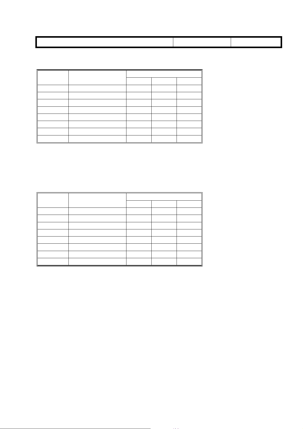
Page 2-49 Paper size detection
Paper size detection for tray 1 (for North America models)
Dial No. Paper Size
1 12" x 18" SEF 0 0 0
2 Others 0 1 1
37
48
58
6 A4 LEF 0 1 0
7 11" x 17" SEF 1 1 0
8 No Cassette 1 1 1
" x 10
1/4
x 14" SEF 1 0 0
1/2
"
" x 11” LEF 1 0 1
1/2
" LEF 0 0 1
1/2
XNOB2 XNOB1 XNOB0
Sensor Status
SEF: Short edge feed
LEF: Long edge feed
Others: SEF – A3, 8" x 13", 8
LEF - 5
1/2
" x 8
1/2
"
" x 13", 8
1/4
" x 13", 13" x 18"
1/2
Paper size detection for tray 1 (for Europe models)
No.:
RG024001
Dial No. Paper Size
1 12" x 18" SEF 0 0 0
2 Others 0 1 1
3 A5 SEF 0 0 1
48
58
6 A4 LEF 0 1 0
7 A3 SEF 1 1 0
8 No Cassette 1 1 1
x 13" SEF 1 0 0
1/2
"
" x 11” LEF 1 0 1
1/2
XNOB2 XNOB1 XNOB0
Sensor Status
SEF: Short edge feed
LEF: Long edge feed
Others: SEF – B4 JIS, 11" x 17", 8
LEF - (B5 JIS, 7
1/4
" x 10
" x 14", 8" x 13", 8
1/2
1/2
", 5
1/2
" x 8
1/2
" x 13", 13" x 18"
1/4
"
RICOH Technical
Bulletin
PAGE: 4/6
Model:
Fresa
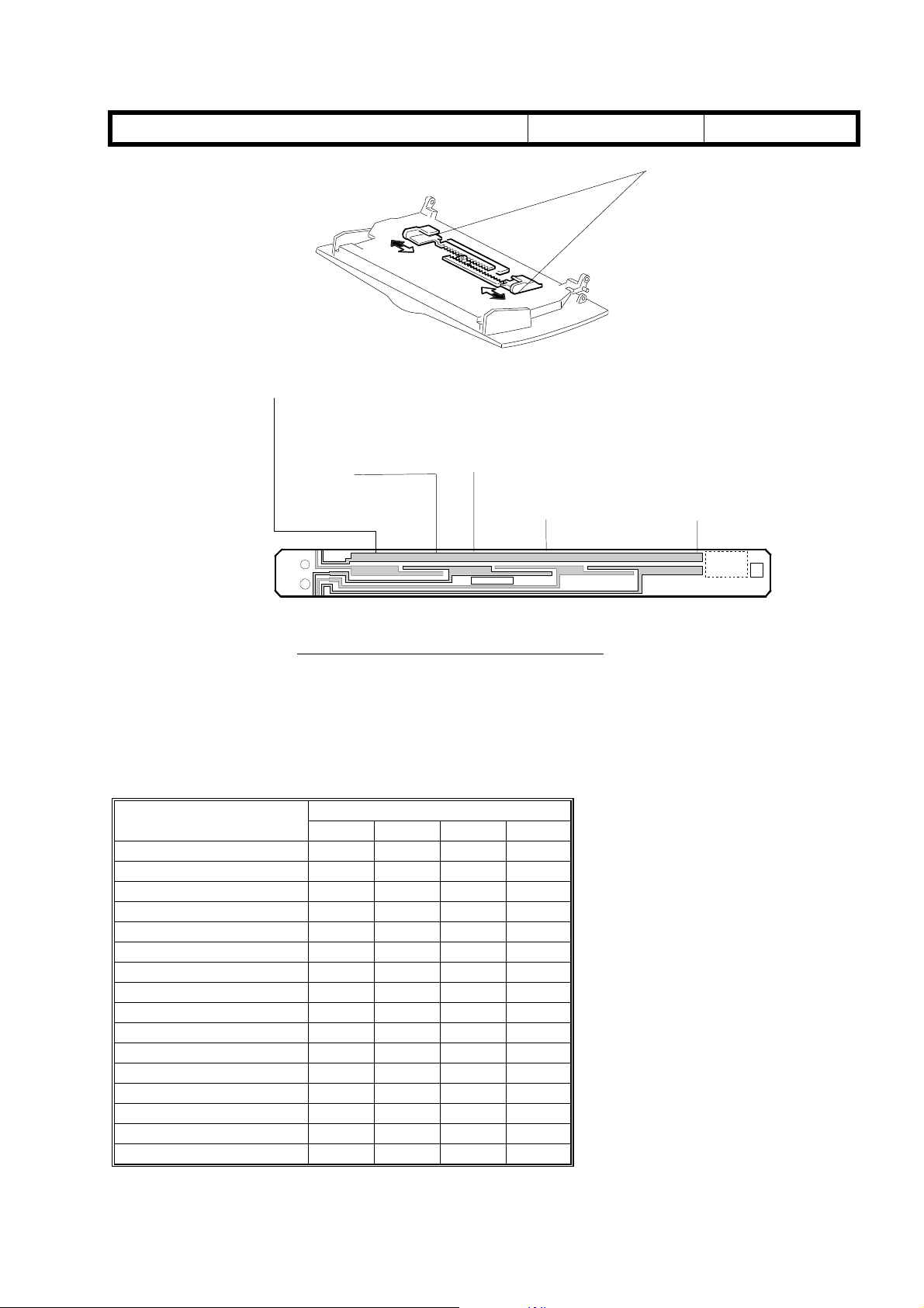
Page 2-52 Paper size detection
A3 WIDE SEF
A3 SEF
A4 LEF
DTL SEF
LT LEF
B4 SEF
B5 LEF
EXE LEF
Date:
G024D410.WMF
A5 LEF
HLT LEF
LG SEF
31-May-99
[A]
No.:
A6 SEF
B6 SEF
RG024001
G024D411. WMF
LEF: Long edge feed SEF: Short edge feed
An electrode plate is connected to each of the two side fences [A]. The electrode plates
short the patterns on the paper size detection board. Paper width is detected from the
locations of the shorting.
Paper size detection for the by-pass feed tray
Paper Size
A3 Wide LEF 1 1 1 0
A4 LEF 1100
A3 SEF 1 1 0 0
81/2" x 11" LEF 1 1 0 0
11" x 17" SEF 1 1 0 0
71/4" x 101/2" LEF 1 1 0 1
B5 JIS LEF 1 1 0 1
B4 JIS SEF 1 1 0 1
81/2" x 14" SEF 1 0 0 1
51/2" x 81/2" SEF 1 0 0 1
A5 LEF 1001
8" x 13" SEF 1001
81/4" x 13" SEF 1 0 0 1
81/2" x 13" SEF 1 0 0 1
B6 JIS SEF 0 1 1 1
A6 SEF 0 1 1 1
XBIT0 XBIT1 XBIT2 XBIT3
Sensor Status
RICOH Technical
Bulletin
PAGE: 5/6
Model:
Fresa
Date:
31-May-99
No.:
RG024001
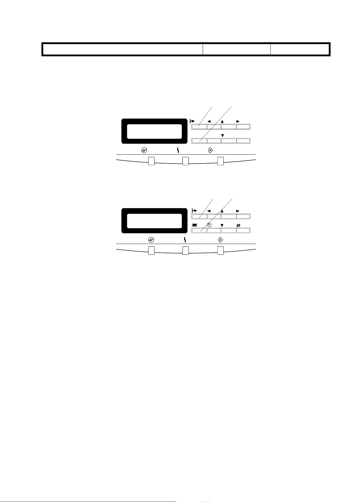
Page 4-1 Entering engine SP mode
To enter engine SP mode, hold down the [Online] [A] and [Menu] [B] keys on the operation
panel and turn on the power.
[A] [B]
On Line
Menu Cancel
ErrorPower Data in
#Enter
G024C500.WMF
[A] [B]
G024C501.WMF
Page 4-2 Key operation
[Cancel] key: Pressing this key moves you to a higher level in the current
menu. Before the specified value is confirmed by the [# Enter]
key, pressing this key keeps the existing setting.
RICOH Technical
Bulletin
PAGE: 6/6
Model:
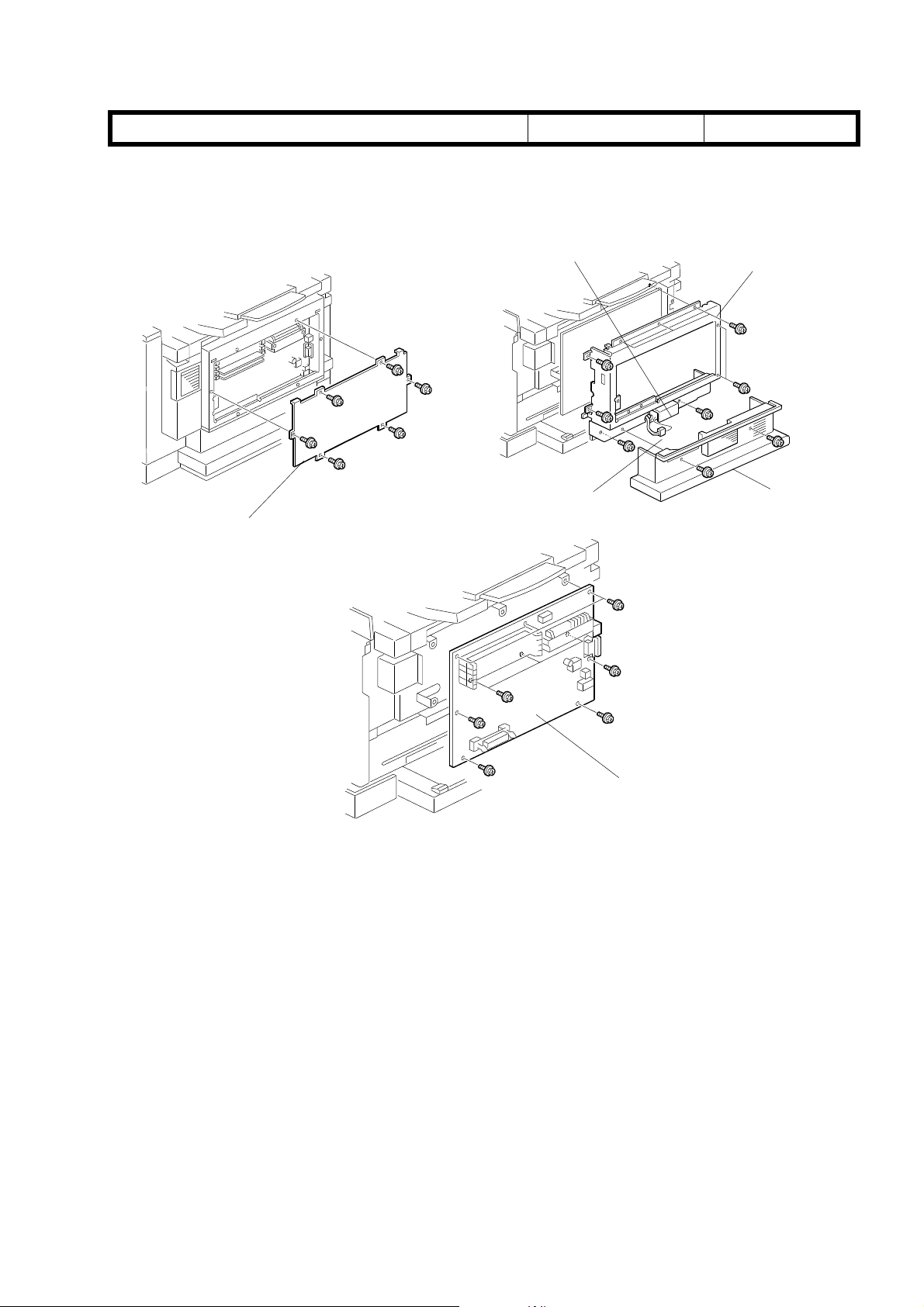
Page 6-35
CONTROLLER BOARD AND TEMPERATURE/HUMIDITY SENSOR REPLACEMENT
NOTE:
Fresa
Print the “Configuration sheet” prior to removing the controller board as the NVRAM cannot be exchanged.
G024R551.WMF
[A]
Date:
[C]
[D]
31-May-99
No.:
RG024001
[E]
[B]
G024R552.WMF
[F]
G024R553.WMF
1. Remove the controller cover [A] (12 screws).
2. Remove the tray cover [B] (two screws).
3. Remove the temperature/humidity sensor cover (one screw) and sensor [C], (one
screw). Make sure to unplug the connector [D].
4. Remove the controller bracket [E] (5 screws).
5. Remove the controller board [F] (6 screws).
After replacing the controller board, make sure that the brand name (and MAC address if
required by the user) stored in the machine is correct.
Technical
Bulletin
PAGE: 1/7
Model: Fresa Date:
Subject:
From:
Classification:
Please correct your service manual as follows.
Engine
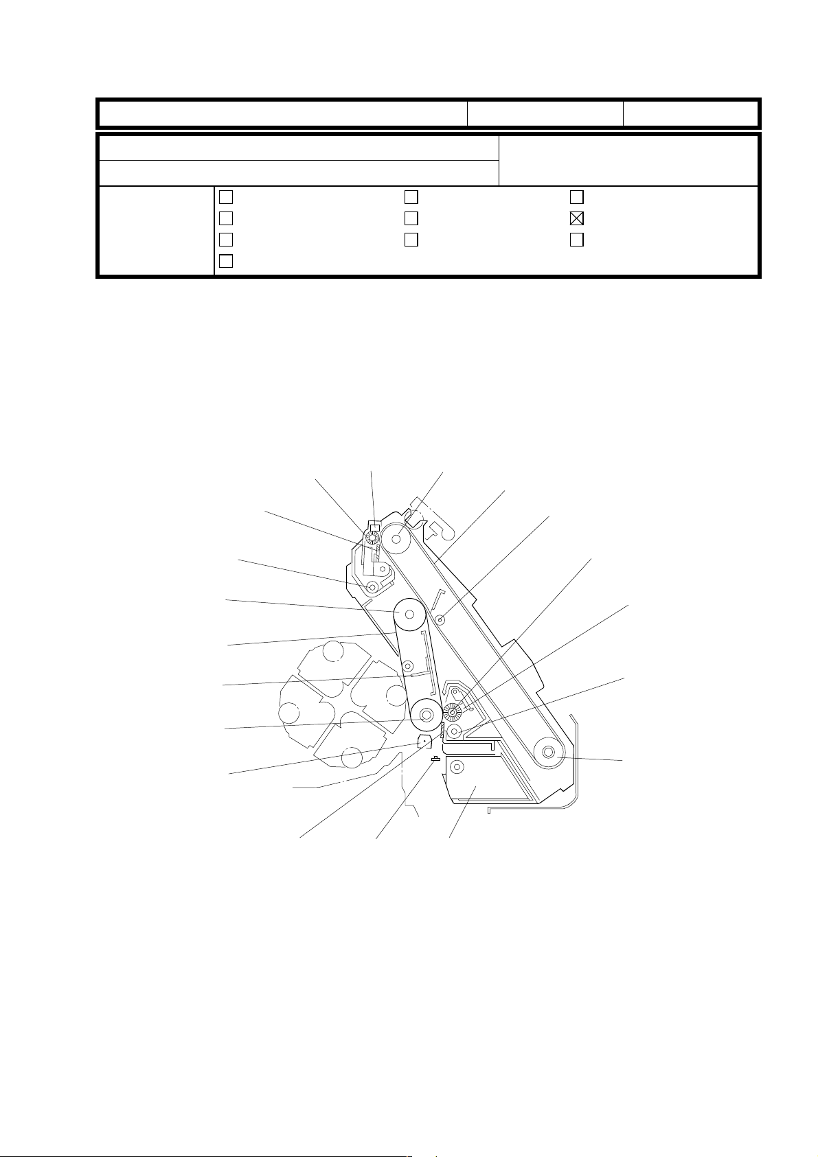
Page 2-6 PCU Overview
The callouts in the illustration below must be corre cted .
Service Manual
Technical Service Dept., GTS Division
Troubleshooting
Mechanical
Paper path
Other ( )
16 15
17
18
Part information
Electrical
Transmit/receive
30-Jun-99
Prepared by:
Action required
Service manual revision
Retrofit information
14
13
No.:
H. Someya
RG024002
19
1
2
3
4
5
12
11
10
9
G024D151.WMF
6
7
8
Technical
Bulletin
PAGE: 2/7
Model: Fresa Date:
Page 2-16 Used Toner Tank
Incorrect
The used toner sensor [D] detects when the tank becomes full. After detecting the toner
near-end condition, the printer can make 20 additional prints before the machine stops
printing.
Correct
The used toner sensor [D] detects when the tank becomes full. After detecting
condition, the printer can make 20 additional prints before the machine stops printing.
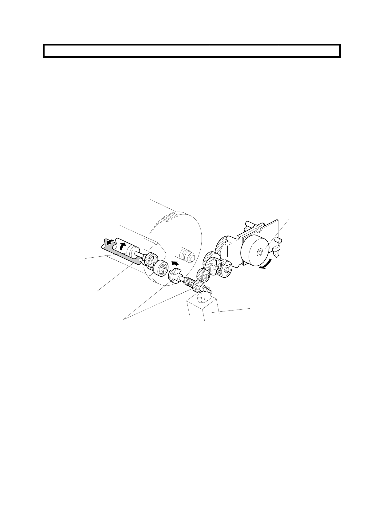
Page 2-32 Development Unit Drive
The callout [A] should be added to the gear.
30-Jun-99
No.:
[B]
RG024002
this
[D]
[C]
[E]
[A]
G024D162.WMF
Technical
Bulletin
PAGE: 3/7
Model: Fresa Date:
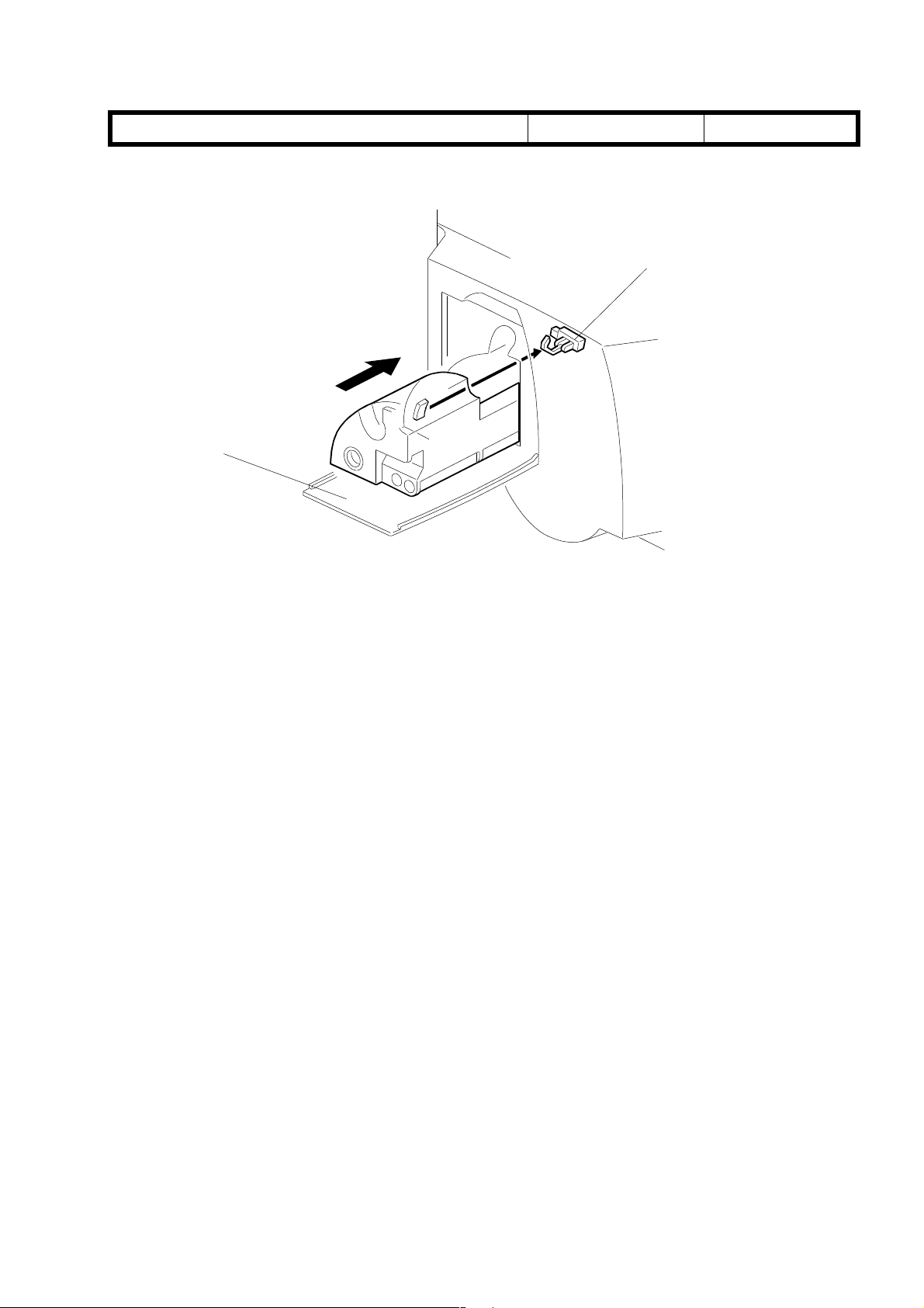
Page 2-36 DTM (Development Toner Magazine) Detection
[B]
30-Jun-99
G024D164.WMF
[A]
No.:
RG024002
Incorrect
Installing a toner bottle and closing the front cover [B] automatically initiates the recovery
procedure, clearing the error.
Correct
Installing a toner bottle and closing the
procedure, clearing the error.
The callout [B] should be added.
Page 4-5 Margin (Registration Adjustment)
Minor corrections should be added to step 3 of this procedure (below). Also, the note
below should be added.
3. Move to the Adjust menu to adjust the vertical and horizontal registrations. The
adjustment range for the horizontal
units with 0.4 mm increments. The adjustment rang e for the ver ti cal
is between –2.5 and +2.5 mm in units with increments of 0.5 mm.
NOTE:
The LCD panel displays the horizontal registration as “Left” and the vertical
registration as “Top”.
DTM cover
registration is between –2.0 and +2.0 mm in
(Left)
[B] automatically initiates the recovery
registration
(Top)
Technical
Bulletin
PAGE: 4/7
Model: Fresa Date:
Page 4-6 Clear Memory
The explanations in the shaded cells below must be corrected.
Layer 1 Layer 2 Layer 3 Layer 4
Clear Memory
SC
Clear Memory
Maintenance
3:Clear Memory
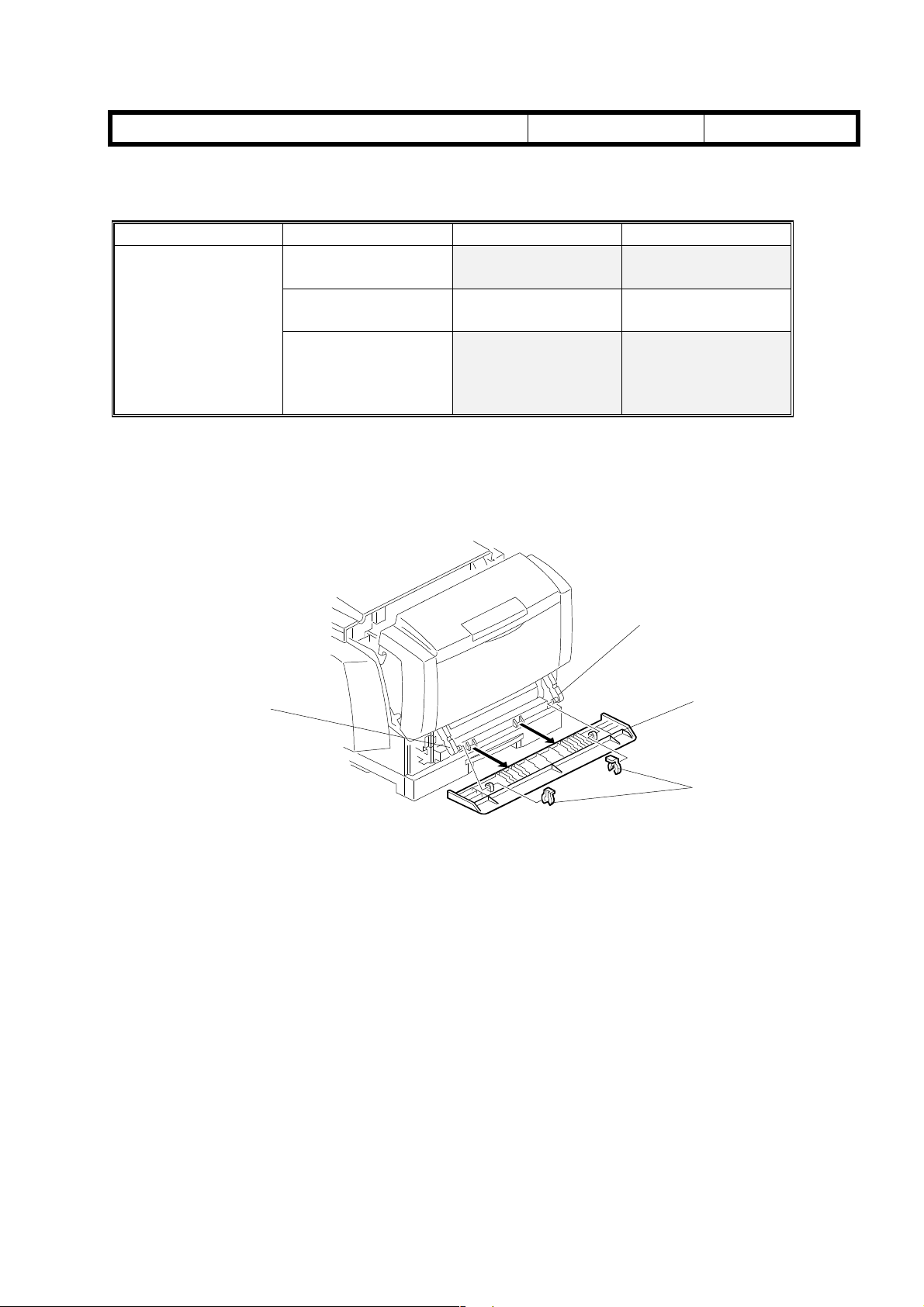
Page 6-3 Bottom Front Cover
A supplementary explanation should be added to the procedure below.
Jam
Clear Memory
All
NOTE:
only.
Factory use
Clear: SC
Press # to clear
Clear: Jam
Press # to clear
Clear: All
Press # to clear
30-Jun-99
Clearing
SC
Clearing
Jam
Clearing
All
No.:
RG024002
[B]
[B]
G024R268.WMF
1. Open the front cover half way, and remove the two snap rings [A].
2. Carefully slide the hinge levers [B] out from the bottom front cover [C].
The levers are spring loaded.
3. Remove the bottom front cover.
[C]
[A]
Technical
Bulletin
PAGE: 5/7
Model: Fresa Date:
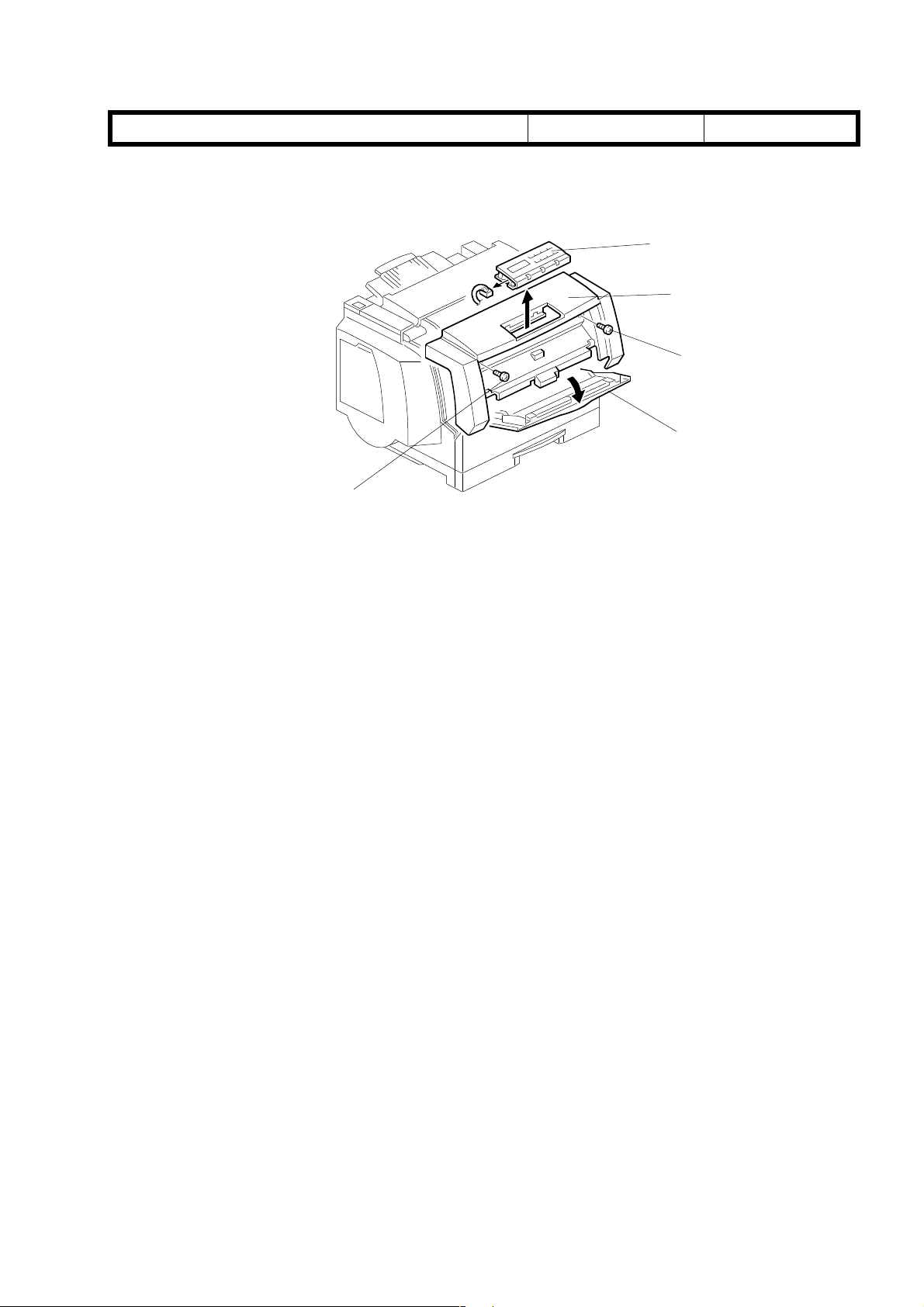
Page 6-3 Front Cover and Operation Panel
A supplementary explanation should be added to the procedure below.
[B]
G024R153.WMF
1. Open the by-pass tray [A].
30-Jun-99
[D]
[C]
[A]
[B]
No.:
RG024002
2. Remove the two screws [B] and carefully lift the front cover [C] from the printer.
3. Remove the operation panel [D] from the front cover (two hooks). Be sure to unplug
the connector from the operatio n panel .
NOTE:
Page 6-7 Calibrating the ID Sensor
A supplementary procedure should be added to steps 2 and 3 below.
2. Select “9: ID Sensor PWM” in the engine SP menu. Specify 150 as the PWM value.
3. Select “7: Process Ctrl” in the engine SP menu. Execute “Color Bias” (this starts the
The surface of the operation panel circuit board is not insulated. When turning on
the printer while the operation panel is being removed from the front cover,
exercise extra caution in order to prevent a short circuit of the board.
Press the [Enter] key. An asterisk (*) is then displayed before the value. Press the
[Escape] or [Menu] key.
process control for the color development bias settings). Wait until “Finish OK” is
displayed. Then press the [Escape] or [Menu] key.
Technical
Bulletin
PAGE: 6/7
Model: Fresa Date:
Page 6-18 LD Unit
The callouts of the illustration below must be corrected.
[E]
[D]
[C]
[E]
G024R259A.WMF
30-Jun-99
No.:
RG024002
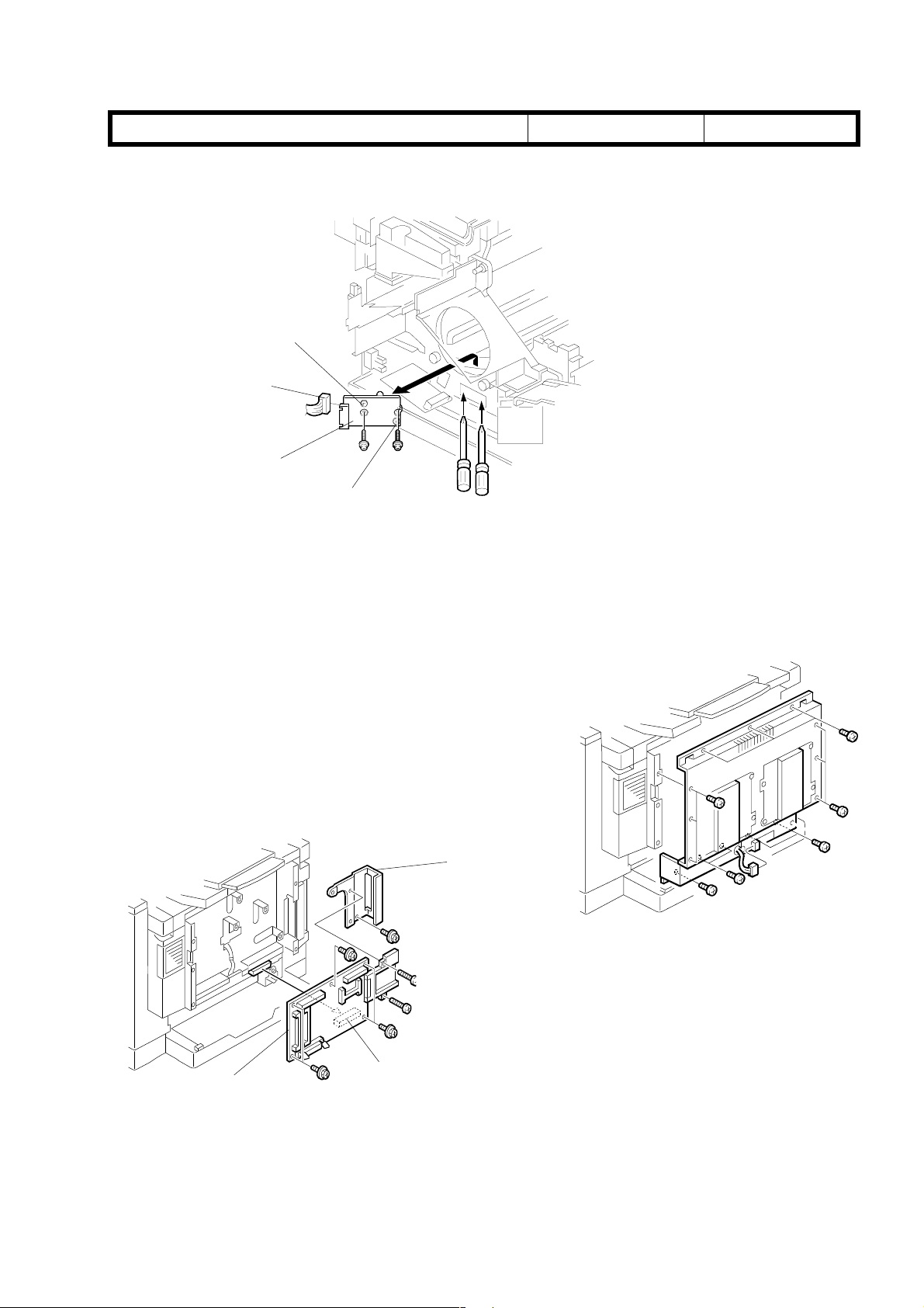
Page 6-35 Controller Board, Temperature/Humidity Sensor
The explanation in step 2 of the procedure and callout [H] should be corrected.
4. Remove the controller cover [E] (16 screws,
including 2 screws around the parallel port).
5. Remove the controller board [F] with the bracket
[G] attached to it (6 screws, 1 connector [H]).
6. Remove the bracket [G] and 2 screws from the
controller board.
[G]
NOTE:
[H]
[F]
G024R166.WMF
To replace the controller boards, remove the
NVRAM chip (IC23) on the old board, install it
on the new board and finally install the new
board itself. The NVRAM chip stores user
settings and service records. These settings
will be lost if the NVRAM chip is not
transferred to the new board.
G024R184.WMF
 Loading...