

Page 1

Color Laser Printer
AP204
OPERATING INSTRUCTIONS
Read this manual carefully before you use this product and keep it handy for future
reference.
For safety, please follow the instructions in this manual.
Page 2

Introduction
This manual contains detailed instructions on the operation and maintenance of this machine. To
get maximum versatility from this machine all operators should carefully read and follow the
instructions in this manual. Please keep this manual in a handy place near the machine.
Please read the Safety Information before using this machine. It contains important information
related to USER SAFETY and PREVENTING EQUIPMENT PROBLEMS.
Power Source
220-240 V, 50/60Hz, 4A or more
Please be sure to connect the power cord to a power source as above.
Operator Safety:
This machine is considered a class 1 laser device, safe for office/EDP use. The machine contains a
5-milliwat, 760 - 800 nanometer wavelength, GaAIAs laser diode. Direct (or indirect reflected) eye
contact with the laser beam might cause serious eye damage. Safety precautions and interlock
mechanisms have been designed to prevent any possible laser beam exposure to the operator.
The following label is attached on the back side of the machine.
Laser Safety:
The optical housing unit can only be repaired in a factory or at a location with the requisite equipment. The laser subsystem is replaceable in the field by a qualified Customer Engineer. The laser
chassis is not repairable in the field. Customer engineers are therefore dir ected to return all chassis
and laser subsystems to the factory or service depot when replacement of the optical subsystem is
require.
Caution:
Use of controls or adjustment or performance of procedures other than those specified in this
manual might result in hazardous radiation exposure.
Do not attempt any maintenance or troubleshooting other than that mentioned in this manual.
This machine contains a laser beam generator and direct exposure to laser beams can cause permanent eye damage.
Two kinds of size notation are employed in this manual. With this machine refer to the Metric
version
Ricoh shall not be responsible for any damage or expense that might result from the use of parts
other than genuine Ricoh parts in your Ricoh office product.
For good copy quality, Ricoh recommends that you use genuine Ricoh toner.
Trademarks
Microsoft
United States and/or other countries.
PostScript
®
, Windows®, and MS-DOS® are registered trademarks of Microsoft Corporation in the
®
is a registered trademark of Adobe System Incorporated.
Other product names used herein are for identification purposes only and might be trademarks of
their respective companies. We disclaim any and all rights in those marks.
Important
Parts of this manual are subject to change without prior notice. In no event will the company be
liable for direct, indirect, special, incidental, or consequential damages as a result of handling or
operating the machine.
Notes
Some illustrations might be slightly different from your machine.
Certain options might not be available in some countries. For details, please contact your local
dealer.
Page 3

Declaration of Conformity
The Product complies with the requirements of the EMC Directive 89/336/EEC and the Low
Voltage Directive 73/23/EEC.
Caution (in case of 100BaseTX environment):
Properly shielded and grounded cables (STP) and connectors must be used for connections to
host computer (and/or peripheral) in order to meet FCC emission limits.
Warning
Changes or modifications not expressly approved by the party responsible for compliance could
void the user’s authority to operate the equipment.
In accordance with ISO Standard 7001, this machine uses the following symbols for the main
power switch:
a means POWER ON.
b means POWER OFF.
Copyright© 1999 Ricoh Co., Ltd.
Page 4
Safety Information
Safety Information
When using your equipment, the following safety precautions should always be
followed.
Safety During Operation
In this manual, the following important symbols are used:
R
WARNING
Indicates a potentially hazardous situation which, if instructions are not followed, could result in death or serious injury.
R
CAUTION
Indicates a potentially hazardous situation which, if instructions
are not followed, may result in minor or moderate injury or damage to property.
R
WARNINGS
• Connect the power cord directly into a wall outlet and never use an extension cord.
• Disconnect the power plug (by pulling the plug, not the cable) if the power
cable or plug becomes frayed or otherwise damaged.
• To avoid hazardous electric shock or laser radiation exposure, do not remove any covers or screws other than those specified in this manual.
• Turn off the power and disconnect the power plug (by pulling the plug, not
the cable) if any of the following conditions exists:
• You spill something into the equipment.
• You suspect that your equipment needs service or repair.
• Your equipment’s cover has been damaged.
• Do not incinerate spilled toner or used toner. T oner dust might ignite when
exposed to an open flame.
• Disposal can take place at our authorized dealer or at appropriate collection sites.
• If you dispose of the used toner containers yourself, dispose of them according to your local regulations.
i
Page 5
R
CAUTIONS
• Protect the equipment from dampness or wet weather, such as rain, snow, and
so on.
• Unplug the power cord from the wall outlet before you move the equipment.
While moving the equipment, you should take care that the power cord will not
be damaged under the equipment.
• When you disconnect the power plug from the wall outlet, always pull the plug
(not the cable).
• Do not allow paper clips, staples, or other small metallic objects to fall inside the
equipment.
• Do not eat or swallow toner.
• Keep toner (used or unused) and toner cassette out of reach of children.
• For environmental reasons, do not dispose of the equipment or expended supply’s
wastes at a household waste collection point. Disposal can take place at out
authorized dealer or at appropriate collection site.
• Our products are engineered to meet the highest standards of quality and functionality . When purchasing expendable supplies, we recommend using only those
provided by an authorized dealer.
• The inside of the machine could be very hot. Do not touch the parts with a label
indicating a hot surface. Otherwise, it could cause a personal burn.
ii
Page 6
Safety Information
ENERGY STAR Program
As an ENERGY STAR Partner, we have determined that this
machine model meets the ENERGY STAR Guidelines for energy efficiency.
The ENERGY STAR Guidelines intend to establish an international energysaving system for developing and introducing energy-efficient office equipment to deal with environmental issues, such as global warming.
This product was designed to reduce the environmental impact associated with
office equipment by means of energy-saving features, such as Low-power mode
(Energy Saver mode).
This printer automatically lowers its power consumption 60 minutes after the
last operation has been completed. T o exit the Low-power (Ener gy Saver) mode,
press any key on the operation panel. To change the setting of the Energy Saver
mode, see page 99.
Recycled paper
Please contact your sales or service representative for recommended recycled
paper types that may be used in this machine.
iii
Page 7
Color Guide
Color Printing Basics
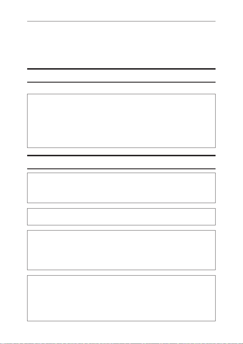
Additive (Emitted) and Subtractive (Reflected) Color Models
All light is a mixture of red, green, and blue, which is normally called the RGB
model. When red, green, and blue are of equal intensities, the RGB color model
produces white.
Note
❐ RGB is also called additive or emitted color. The colors on your computer
screen are produced by varying the intensities of RGB.
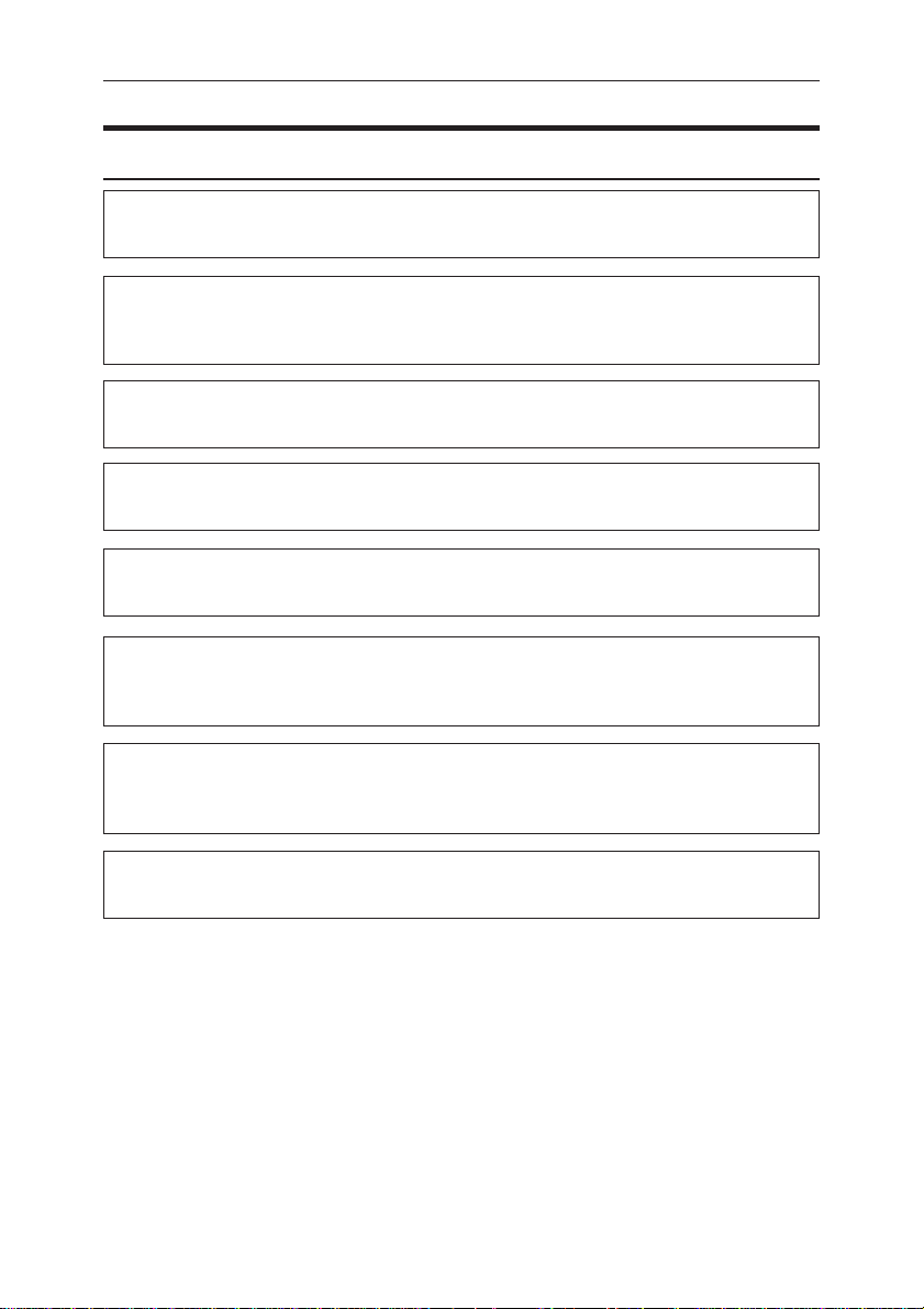
Printed color is a mixture of cyan, magenta, and yellow , which is normally called
the CMY color model. When mixed in equal proportions the CMY color model
produces black.
Note
❐ CMY is also called subtractive or reflective color . Y our printer uses CMY toner
plus K (black) toner (CMYK color model) to provide full color printing.
iv
Page 8

Color Guide
The colors of the RGB color model can be mixed to produce the cyan, magenta,
and yellow of the CMY color model and vice versa. Two colors of one model are
mixed to produce the color of the other model (mixing blue and green produces
cyan, for example). The remaining color is the compliment of the color produced
(red in this example). Complimentary colors are: red and cyan, green and magenta, blue and yellow.
v
Page 9

Printed Color
Your printer produces full-color output using four toner colors: cyan, magenta,
yellow, and black. These four colors make up the CMYK color model.
Note
❐ Mixing CMY in equal proportions should hypothetically produce pur e black,
but imperfections in the ink cause an equal measure of these colors to produce
a muddy or dark brown. Black toner is added to the color model in order to
make it possible to produce pure black.
If an image consisted of nothing by cyan, for example, cyan toner would be used
by itself and there would be no problem producing the desired color. Full-color
printing, on the other hand, required repr oduction of tens of thousands of subtle
colors. These can be produced by controlling the relative pr oportions of the CMYK
toner particles printed within a unit area.
Relatively dense and light shades of the same color also can be reproduced by
controlling the volume of toner in a unit area.
vi
Page 10
Color Guide
Example of Color Adjustments Using the Printer Driver
The following provides a number of examples to show you what happens when
you change the various color settings provided in the printer driver.
Quality Settings
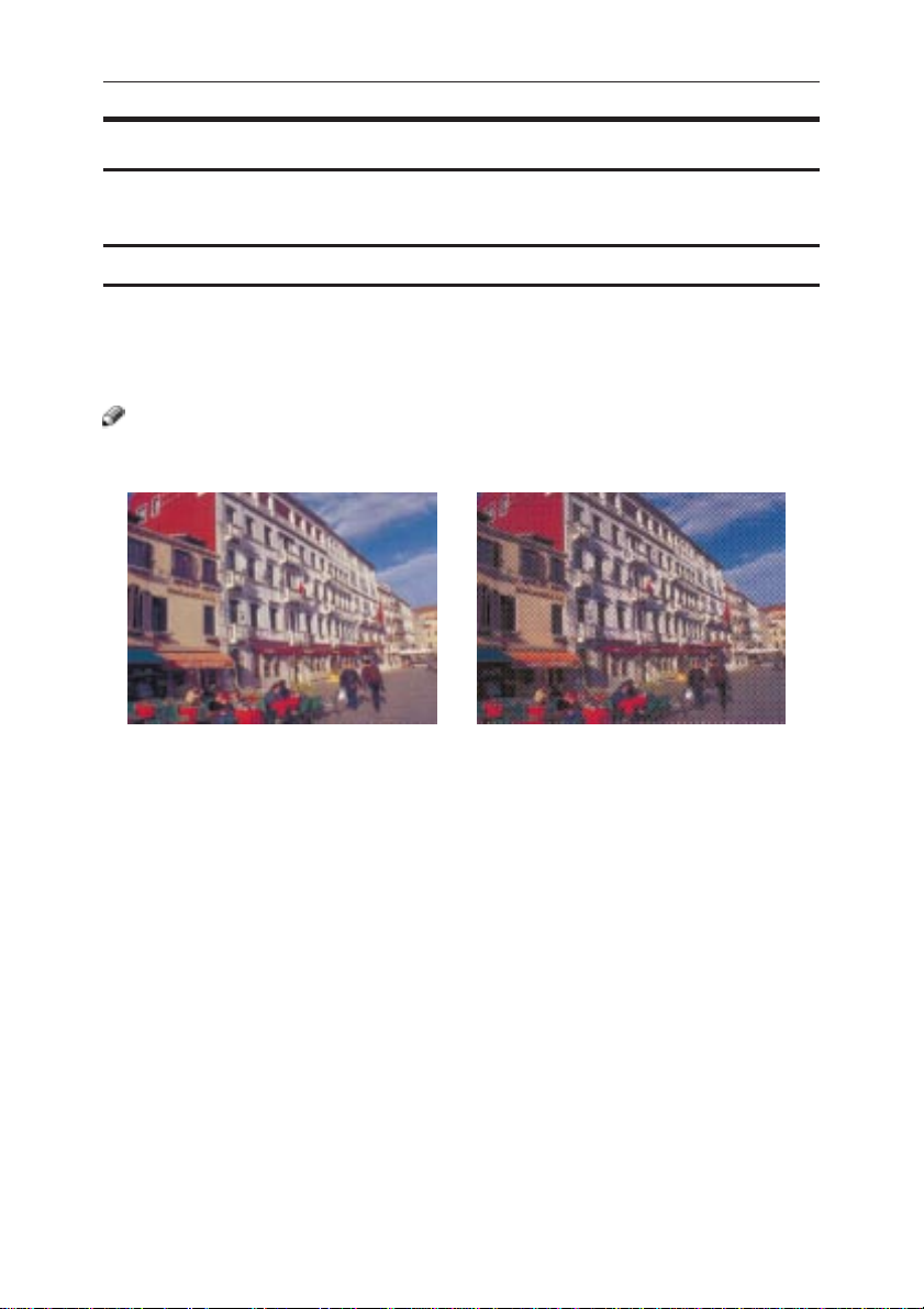
Resolution
Resolution is the number of dots the printer can print within one inch. The
higher the resolution, the better the quality of the printed image. Resolution is
expressed in units of dpi, which stands for dots per inch.
Note
❐ Printing at a high resolution takes longer and requires mor e printer memory.
600dpi 300dpi
vii
Page 11
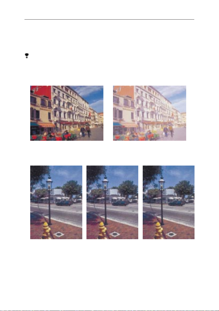
Toner Saving
Turning on Toner Saving reduces the amount of toner used for printing. This
setting does not help to improve printout quality, but instead is used when
printing preliminary drafts of a document.
Limitation
• Turning on the Toner Saving can cause output to become blurred and result in very thin lines not printing at all. It can cause colors to be different
than expected when printing color.
Off On
Image Printing
This setting lets you select the resolution for printing of image data.
Standard Fast Fine
viii
Page 12
Color Guide
Color Settings
The colors produced by the printer do not exactly match those you see on your
monitor . This is because the computer uses the reflected color model (RGB) while
the printer uses the emitted color model (CMYK). For details, see => P.iv “Color
Printing Basics”. The color settings provide you with a number of adjustments
that you can use to bring printed colors closer to what they look like on your
monitor . Y ou can also use these settings to perform color correction, which changes
the clarity of the image.
You can change the color settings with the printer driver.
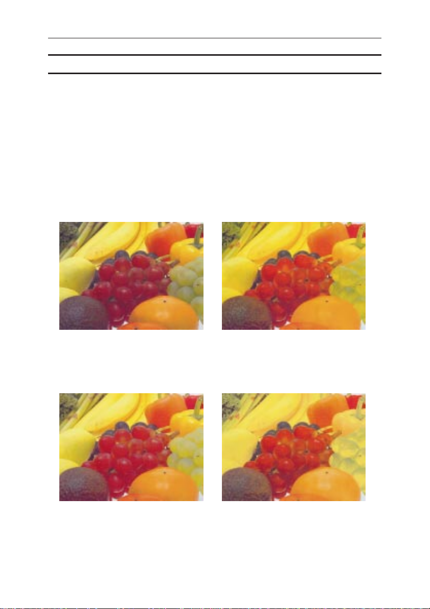
Color Correction
Use these settings to adjust the color correction pattern.
Off Photographic
This setting enhances midtone colors similar to those seen in photographs.
Vivid OHP Transparency
This setting enhances the basic colors for text and graphics. This setting is best for printing tables,
graphs, and presentation materials
that contain color.
This setting adjusts density to an
optimal level for printing OHP
transparencies.
ix
Page 13
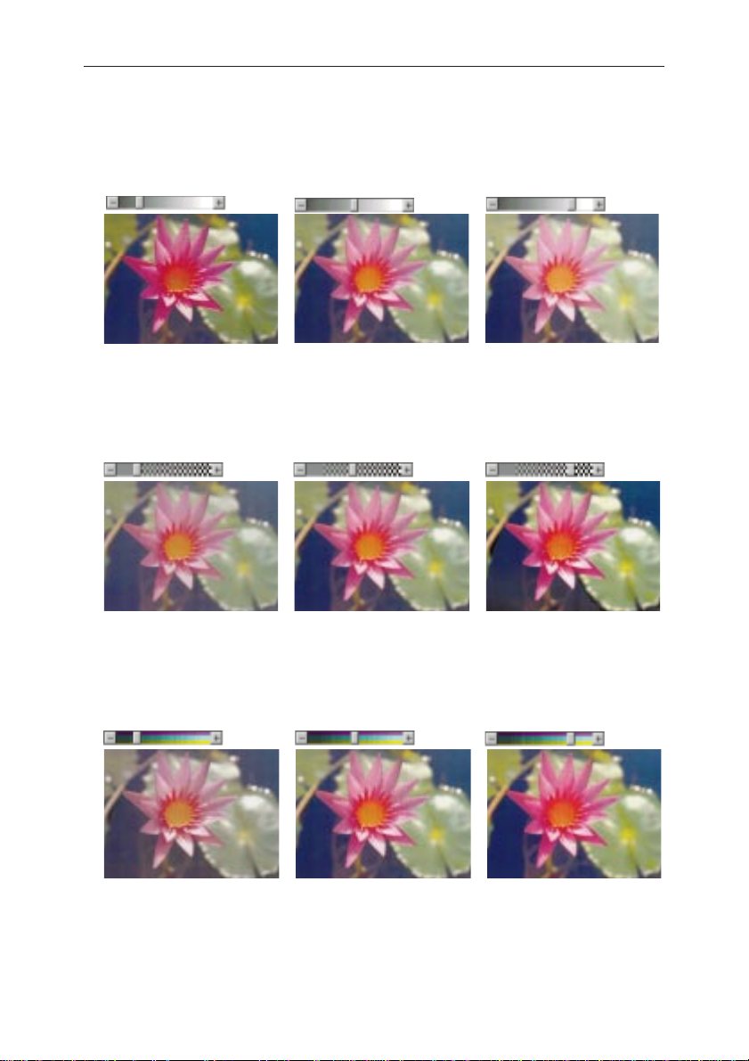
Brightness
This setting controls the overall brightness of the image. Moving the slider to
the plus (+) side increase brightness, while moving it to the minus (-) side
decreases brightness.
-30 0 +30
Contrast
This setting controls the range between the darkest and lightest shade of an
image. Moving the slider to the plus (+) side decreases the range and makes
contrast stronger, while moving it to the minus (-) side expands the range.
-30 0 +30
Saturation
x
This setting controls the purity of a color. Moving the slider to the plus (+)
side increases saturation and makes colors more vivid, while moving it to the
minus (-) side decreases saturation.
-30 0 +30
Page 14
Color Guide
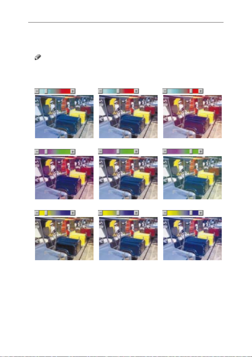
Color Balance
These settings let you control the relative intensity of the individual colors of
the additive color model (red, green, blue).
Note
❐ The position of the color bar also affects the complementary color relation-
ship. Red, for example, is printed using magenta and yellow toner, so increasing the level of red also decreases the level of cyan.
-30 0 +30
-30 0 +30
-30 0 +30
xi
Page 15

Manuals for Your Printer
There are two manuals that describe the procedures separately for the installation of your printer and for the operation and maintenance of your printer and
its optional equipment.
T o enhance safe and efficient operation of your printer, all users should read and
follow the instructions contained in the following manuals.
❖
Quick Installation Guide
Describes the procedures for installing your printer.
❖
Operating Instructions
Describes the procedures and necessary information on setting up and using
your printer and its optional equipment. (This Manual)
xii
Page 16

How to Read this Manual
How to Read this Manual
Symbols
In this manual, the following symbols are used:
R
WARNING:
This symbol indicates a potentially hazardous situation which, if instructions
are not followed, could result in death or serious injury.
R
CAUTION:
This symbol indicates a potentially hazardous situation which, if instructions
are not followed, may result in minor or moderate injury or damage to property.
* The statements above are notes for your safety.
Important
If this instruction is not followed, paper might be misfed, originals might be
damaged, or data might be lost. Be sure to read this.
Preparation
This symbol indicates the prior knowledge or preparations required before
operating.
Note
This symbol indicates precautions for operation, or actions to take after missoperation.
Limitation
This symbol indicates numerical limits, functions that cannot be used together ,
or conditions in which a particular function cannot be used.
Reference
This symbol indicates a reference.
{ }
Keys built into the machine’s operation panel. Keys on the computer’s keyboard.
[]
Keys that appear on the machine’s panel display . Keys and buttons appear on
the computer’s display
xiii
Page 17

Table of Contents
Safety Information....................................................................................... i
Color Guide................................................................................................ iv
Color Printing Basics .....................................................................................iv
Example of Color Adjustments Using the Printer Driver...............................vii
Manuals for Y our Printer ..........................................................................xii
How to Read this Manual........................................................................ xiii
Symbols....................................................................................................... xiii
1. Getting Acquainted
Features of Y our Printer............................................................................. 1
Office Color Printer ........................................................................................ 1
Guide to the Printer.................................................................................... 2
Exterior - Front View ...................................................................................... 2
Exterior - Rear View....................................................................................... 3
Interior ...........................................................................................................4
Operation Panel............................................................................................. 5
2. Installing Options
Available Options....................................................................................... 8
Installing the Memory Unit ........................................................................ 9
Installing the RICOH-SCRIPT 2 Type204................................................ 11
Installing the Network Interface Board Type204 ................................... 13
Installing the IEEE 1284 Parallel Type204.............................................. 15
Installing the Paper Feed Unit Type204 .................................................17
Installing the Paper Cassette Type204................................................... 21
3. Configuring the Printer for the Network with the Operation Panel
Configuring the Printer for the Network with the Operation Panel ..... 23
xiv
Page 18

Table of Contents
4. Installing the IPDL-C Printer Driver
Before Installing the Printer Drivers....................................................... 29
Installing the Printer Drivers ........................................................................ 29
Windows 95/98 - Installing the IPDL-C Printer Driver ...........................30
Installing the Printer Driver Using Plug and Play......................................... 31
Installing the Printer Driver Without Using Plug and Play............................ 34
Setting Up Options ...................................................................................... 36
Canceling a Print Job .................................................................................. 37
Windows 3.1x - Installing the IPDL-C Printer Driver .............................38
Installing the Printer Driver .......................................................................... 38
Setting Up Options ...................................................................................... 40
Canceling a Print Job .................................................................................. 41
Windows NT4.0 - Installing the IPDL-C Printer Driver .......................... 42
Installing the Printer Driver .......................................................................... 42
Setting Up Options ...................................................................................... 44
Canceling a Print Job .................................................................................. 45
5. Paper and Other Media
Paper and Other Media Supported by this Printer................................ 47
Paper Types and Sizes ................................................................................ 47
Precautions for Paper .................................................................................. 48
Printable Area.............................................................................................. 50
Loading Paper .......................................................................................... 51
Loading Paper in the Paper Tray.................................................................. 51
Switching between Paper Trays................................................................... 54
6. Tr oubleshooting
Error & Status Messages......................................................................... 55
Printed Error Message................................................................................. 55
Error & Status Messages on the Operation Panel....................................... 56
Getting Printer Information over the Network .............................................. 60
Printer Doesn’t Print ................................................................................ 65
Other Printing Problems.......................................................................... 67
Removing Misfed Paper........................................................................... 71
When the Message “Remove Misfeed From Tray” Appears........................ 72
When the Message “Open Rear Cover Remove Misfeed” Appears............ 73
When the Message “Remove Misfeed From Output Tray” Appears ............ 74
Cleaning and Adjusting the Printer ........................................................75
Cleaning the Charge Wire ........................................................................... 75
Adjusting the Image Density........................................................................ 77
Adjusting the Setting of “Registration” of the Optional Tray......................... 78
xv
Page 19

Replacing Consumables .........................................................................80
Replacing the Toner Cartridges ................................................................... 80
Replacing the Photoconductor Unit ............................................................. 82
Replacing the Waste Toner Bottle................................................................ 86
Replacing the Fuser Oil Bottle and Ozone Filter ......................................... 87
Replacing the Fuser Cleaner....................................................................... 89
7. Making Printer Settings with the Operation Panel
Setting Menus........................................................................................... 92
Protecting the Menus............................................................................... 94
Protecting the Menus................................................................................... 94
Changing the Menu Settings without Removing Protect ............................. 95
Removing Protect ........................................................................................ 96
Menu Table................................................................................................ 97
Menu Settings........................................................................................... 98
IPDL-C Menu............................................................................................... 98
System Menu............................................................................................... 98
Printing the Configuration Page ........................................................... 101
Interpreting Configuration Page ...........................................................102
Reference .................................................................................................. 102
Printer Information ..................................................................................... 102
Status List.................................................................................................. 103
Error Log.................................................................................................... 103
Printing the Color Sample .....................................................................104
Resetting Menus ....................................................................................105
8. Appendix
Memory Capacity and Paper Size......................................................... 107
Moving and Transporting the Printer ...................................................109
Specifications......................................................................................... 110
Mainframe.................................................................................................. 110
Options ...................................................................................................... 112
Comsumbles........................................................................................... 114
Glossaries............................................................................................... 115
Index........................................................................................................ 117
xvi
Page 20

1. Getting Acquainted
Features of Your Printer
Office Color Printer
You can enjoy the versatility of a full color printer and the performance of a
monochrome laser in a single compact unit. Text, spreadsheets, presentations,
design and other documents containing images can be beautifully printed in full
color. Windows applications using monochrome text or gray scale images are
rendered quickly in razor-sharp detail. Its compact design allows you to locate it
in a small convenient place. The efficient design of the internal mechanism make
it easy to access and replace consumables as paper and toner cartridge.
1
Page 21
Getting Acquainted
8
Guide to the Printer
1
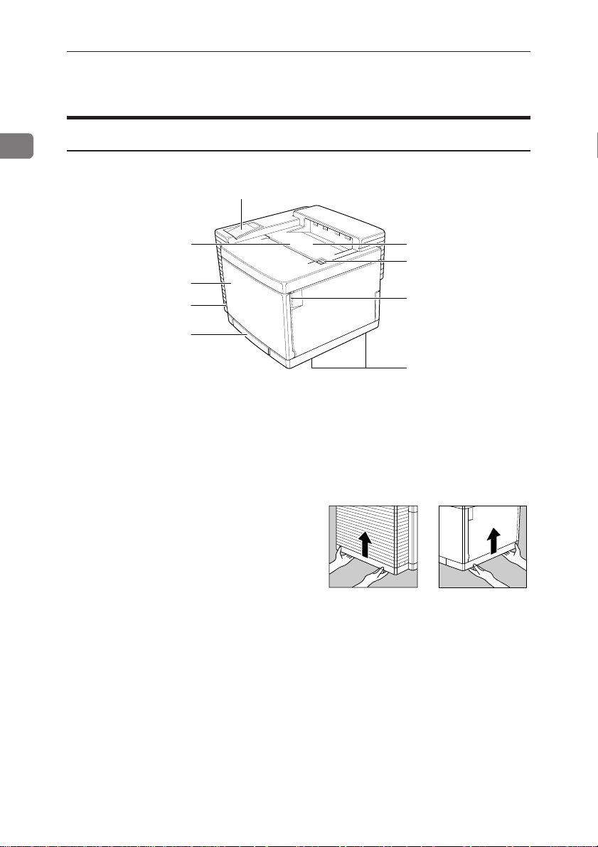
Exterior - Front View
1
2
3
4
5
1. Operation Panel
Contains keys for printer operation
and a display that shows the printer
status. =>P.5 “Operation panel”
2. Top Cover
Open this cover when accessing the
inside of the printer.
3. Front Cover
Open this cover when accessing the
inside of the printer.
4. Power Switch
Use this switch to turn printer
power on and off.
5. Paper Tray
Load up to 250 sheets of plain pa-
1
into this tray for printing. Y ou
per*
can also load OHP transparencies
and custom paper sizes. => P.51
“Loading Paper in the Paper Tray”
*1:80 g/m
2
(metric version),
20 lb (inch version)
9
7
6
TPOH010E
6. Inset Grips
Hold the printer at the location indicated in the illustration when
transporting it. Note that there are
four grips, two on the left side and
two on the right side of the printer .
7. Front Cover Open Lever
Press this lever to open the front
cover.
8. Top Cover Open Lever
Press this lever to open the top
cover.
9. Output Tray
Printed pages are stacked here with
the print side down.
TPOH020E
2
Page 22
Guide to the Printer
6
5
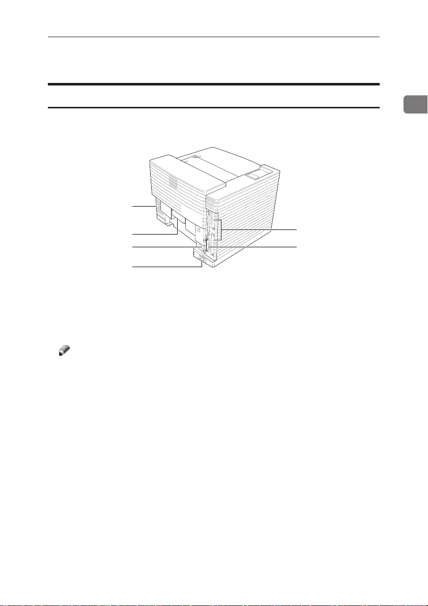
Exterior - Rear View
1
2
3
4
1. Ventilator
These holes help to keep components inside the printer from overheating. Also, this cover should be
removed to replace the ozone filter .
Note
❐ Do not leave the ventilator ob-
structed or blocked. Doing so
creates the danger of malfunction due to overheating.
2. Rear Cover
Open this cover to remove misfed
paper.
3. Power Connector
Connect the power cord to this connector.
4. Optional Paper Feed Unit Connec-
tor Cover
When installing the optional paper
feed unit, plug its cable into this
connector.
1
TPOH030E
5. Parallel Interface Connector
Plug the interface cable that connects the printer to your computer
into this connector.
6. Metal Plates
Remove to install certain options.
3
Page 23

Getting Acquainted
1
Interior
1. Fuser Cleaner
This cleans unnecessary toner from
the fuser roller.
2. Fuser Oil Bottle
This bottle holds oil used for fusing toner on the paper.
3. Photoconductor Unit
This contains a photoconductor
unit belt that is used to compose the
image being printed.
Note
❐ The condition of the photo-
conductor unit belt directly affects output appearance and
quality . Always be careful to prevent the green film in this unit
from becoming dirty or damaged.
4. Toner Cartridges
1 K: black toner
2 Y: yellow toner
3 M: magenta toner
4 C: cyan toner
5. Waste Toner Bottle
This bottle is a receptacle for waste
toner generated during the printing
process.
4
Page 24
Guide to the Printer
Operation Panel
Important
❐ Never press any operation panel keys while the Data In indicator is flashing
on the operation panel.
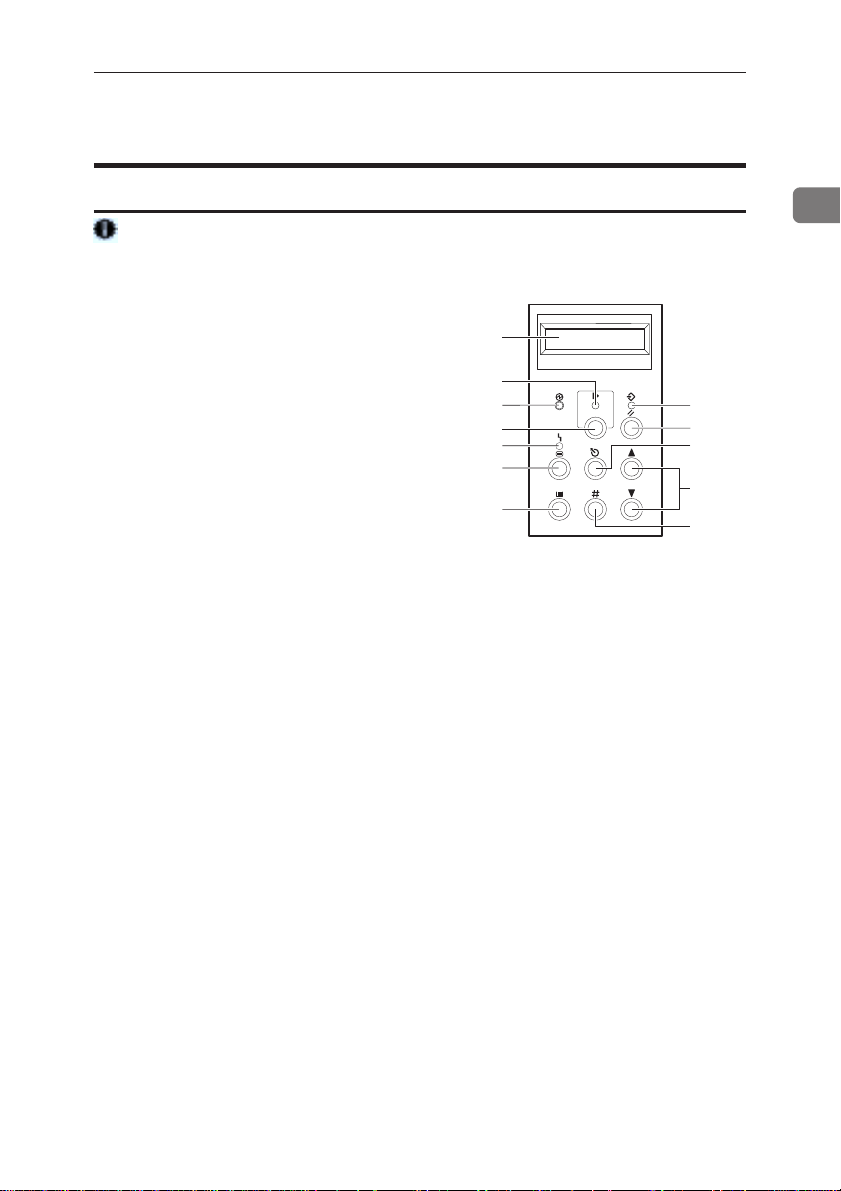
1. Panel Display
The display shows the current status of the printer and error messages. => P.56 “Error & Status Mes-
sages on the Operation Panel”
2. On Line indicator
T ells you whether the printer is online or off-line.
Stays on while the printer is on-line
(a state in which the printer can receive data from the computer).
Stays off when the printer is off-line
(a state in which printer can not receive data).
3. Power indicator
Stays on while the printer power is
on. Stays off when the power is
turned off or while the printer is in
the Energy Saver mode.
On Line
4. {
} key
Press this key to switch the printer
between on-line and off-line conditions.
5. Error indicator
Lights up whenever any printer error occurs. A message describing
the cause of the error also appears
on the panel display.
Menu
6. {
} key
Press this key to make and check the
printer settings.
Media
7. {
} key
Use this key to select a tray, change
the paper size, and to make other
settings for printing.
1
2
3
4
5
6
7
TPOS010G
Enter
8. {
} key
Press this key to execute menu
items selected on the panel display .
9. {U} {T} keys
Use these keys to increase and decrease values on the panel display,
and toggle menus when making
settings.
10.{Escape
} key
Press this key to return to the previous condition on the panel display.
11
. {
Reset
} key
Pressing this key when the printer
is off-line resets the printer to its
power on default settings.
Pressing this key during the on-line
condition cancels the ongoing print
job.
12
.Data In indicator
Blinks while the printer is receiving
data from the computer.
Stays on if there is data to be
printed.
12
11
10
9
8
1
5
Page 25

1
Getting Acquainted
6
Page 26

2. Installing Options
R
CAUTION
• Make sure to turn off the printer and wait for about 30 minutes before installing options. Not waiting for the printer to cool down can result in a burn.
• It is recommended that at least two persons are used to lift the machine.
Otherwise, the machine might fall and cause personal injury.
• When lifting the machine, use the inset grips on both sides of the machine.
Otherwise, the machine might fall and cause personal injury.
R
CAUTION
• When you move the machine, unplug the power cord from the wall outlet to
avoid a fire or an electric shock.
7
Page 27
2
Installing Options
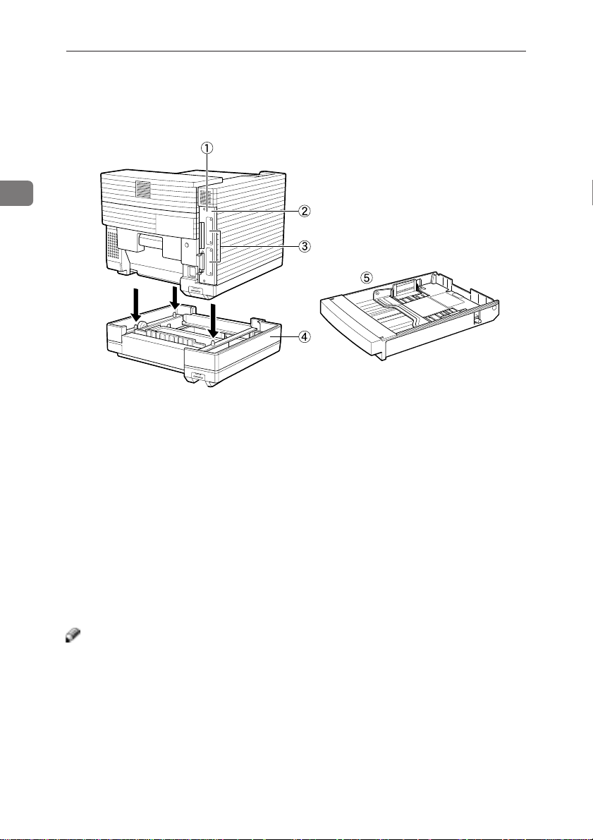
Available Options
The following options can be installed to your printer.
TPOH350E
1. Memory Unit
You can install one of the following memory units.
• Memory Unit Type204 (16MB)
• Memory Unit Type204 (32MB)
2. RICOH-SCRIPT 2 Type204
3. Interface Board
You can install up to two interface boards. However, you cannot install two
boards of the same type at the same time. The following board are available.
• Network Interface Board Type204
• IEEE 1284 Parallel Type204
4. Paper Feed Unit Type204
5. Paper Cassette Type204
Note
❐ You cannot install more than one paper feed unit at a time.
❐ The standard tray or the tray of the optional paper feed unit can be replaced
with Paper Cassette Type204.
TPOH351E
8
Page 28
Installing the Memory Unit
Installing the Memory Unit
Important
❐ The memory unit can be damaged
by small amounts of static electricity. Before touching it, touch something metal to remove static electricity from you.
A T urn off the printer’ s power switch
and remove all cables and cords
from the printer.
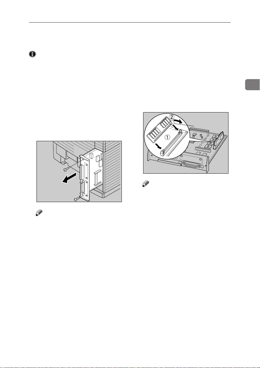
B Remove both screws and remove
the printer board from the printer
as shown in the illustration.
TPOP130E
Note
❐ A coin can be used to remove the
screws.
C Align the memory unit as shown
in the illustration. Tilt it backwards so that it is 45 degrees from
perpendicular to the printer board
11
(
1), and slide it into the slot. Then
11
tilt it forwards so that it is perpendicular to the board (
make an audible click as it pops
into place.
Note
❐ When aligning the memory unit,
notice that the lower corner of
one side has a notch (a). This is
to prevent you from installing
the unit backwards.
22
2). It should
22
(a)
TPOP140E
2
9
Page 29
Installing Options
2
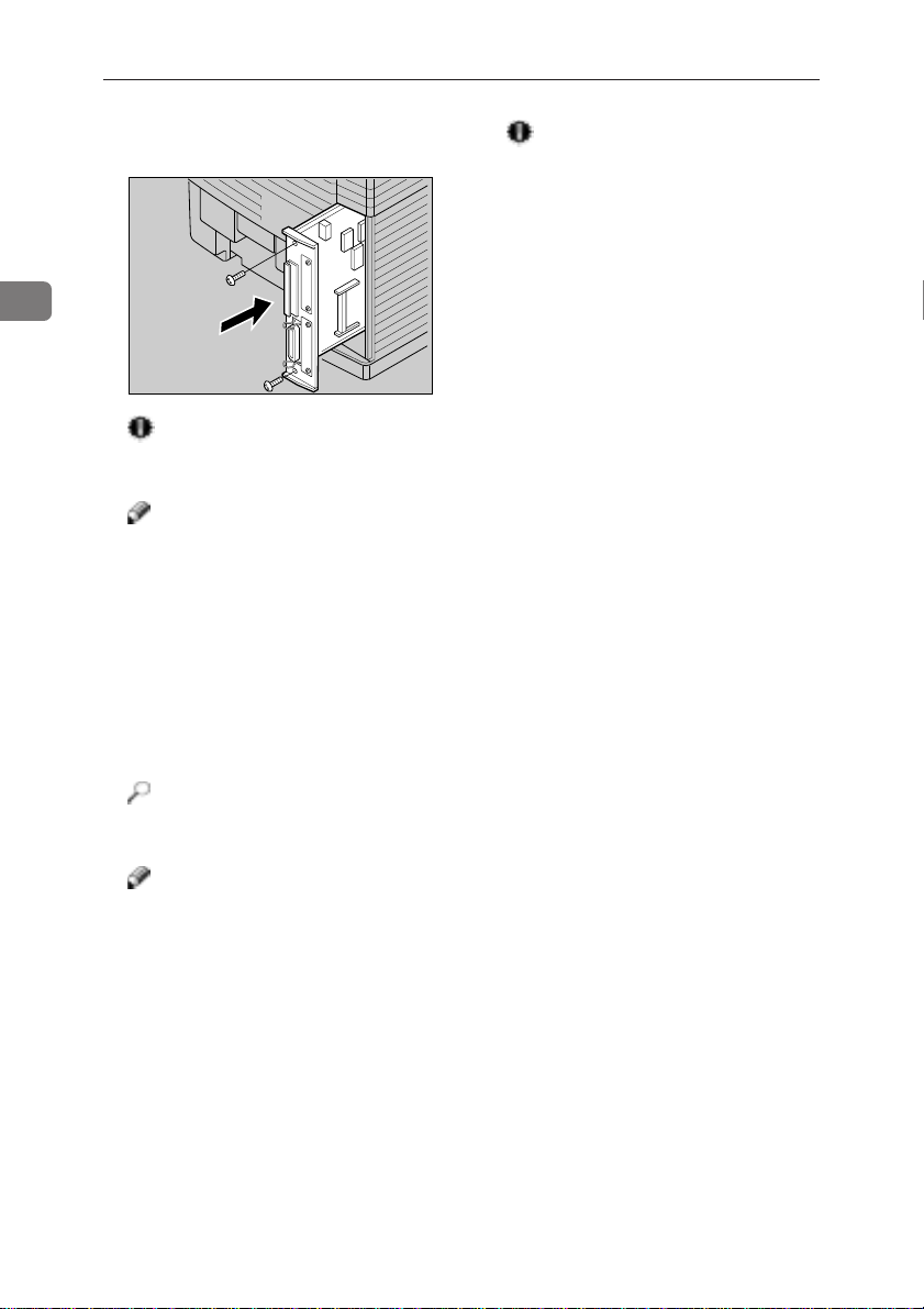
D Insert the printer board into the
printer. Fasten both screws.
TPOP150E
Important
❐ Make sure that both screws are
used to secure the printer board.
Note
❐ A coin can be used to fasten the
screws.
E Plug the printer’s power cord back
into the printer and the wall outlet. Turn on the printer ’s power
switch.
F Print a configuration page to con-
firm that the memory unit is properly installed.
Reference
❐ =>P.101 “Printing the Configura-
tion Page”
Note
❐ You can check if the memory unit
is installed properly by checking
the “Total Installed RAM” item
of the “Reference” on the configuration page.
❐ If the memory unit is not prop-
erly installed, repeat steps A-F
again. If you fail again, contact
your sales or service representative.
Important
❐ To make the printer recognize
the installed option properly,
you must set up the option with
the printer driver . => P.36, 40, or
44 “Setting Up Options”
10
Page 30
Installing the PostScript2 kit Type 204
Installing the RICOH-SCRIPT 2 Type204
Important
❐ The RICOH-SCRIPT 2 can be dam-
aged by small amounts of static
electricity . Before touching it, touch
something metal to remove static
electricity from you.
A Check the contents of the box for
the following items.
• DIMM (Dual Inline Memory
Module)
• Installation Guide
• Operating Instructions
B T urn off the printer’ s power switch
and remove all cables and cords
from the printer.
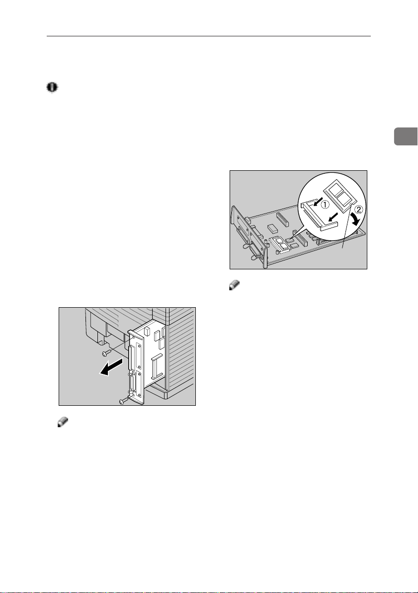
C Remove both screws and remove
the printer board from the printer
as shown in the illustration.
TPOP130E
Note
❐ A coin can be used to remove the
screws.
D Align the module as shown in the
illustration. Tilt it upwards so that
it is 45 degrees from parallel to the
printer board (
the slot. Then tilt it down so that
it is parallel to the board (
should make an audible click as it
pops into place.
Note
❐ If the optional interface board
has been installed to the printer
board, you should remove it
from the board before installing
the module. After installing the
module, reattach the interface
board to its original position.
❐ Be careful to notice that one side
of the module has a notch (a).
This is to prevent you from installing the module backwards.
11
1), and slide it into
11
22
2). It
22
(a)
TPOP160E
2
11
Page 31
2
Installing Options
E Insert the printer board into the
printer. Fasten both screws.
TPOP320E
Important
❐ Make sure that both screws are
used to secure the printer board.
Note
❐ A coin can be used to fasten the
screws.
F Plug the printer’s power cord back
into the printer and the wall outlet. Turn on the printer ’s power
switch.
G Print a configuration page to con-
firm that the module is properly
installed.
Reference
❐ => P.101 “Printing the Configura-
tion Page”
Note
❐ You can check if the module is
installed properly by checking
the “Firmware Version” item of
the “Reference” on the configuration page.
❐ If the module is not properly in-
stalled, repeat steps A-F again. If
you fail again, contact your sales
or service representative.
12
Page 32
Installing the Network Interface Board Type 204
Installing the Network Interface Board
Type204
Note
❐ Use a shielded network interface
cable.
❐ The network interface board can be
attached to either the front or the
back side of the printer board. This
procedure is for attaching to the
front side.
❐ You cannot install two network in-
terface boards at a time.
A Check the contents of the box for
the following items.
• Network interface board
• Ferrite core
• Installation Guide
B T urn off the printer’ s power switch
and remove all cables and cords
from the printer.
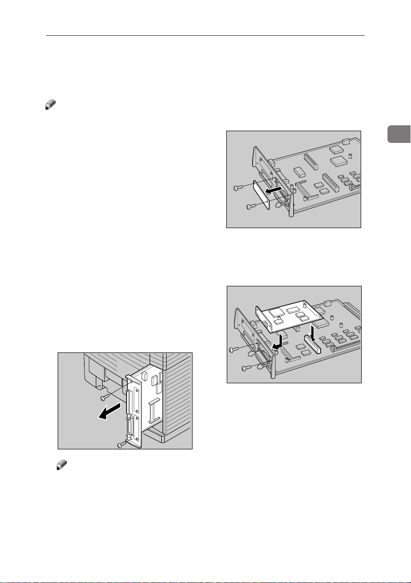
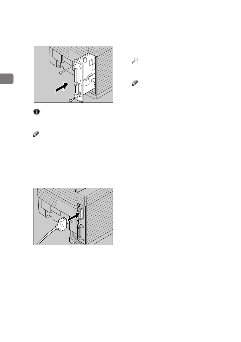
C Remove both screws and remove
the printer board from the printer
as shown in the illustration.
D Remove both screws and the metal
plate from the printer board.
TPOP170E
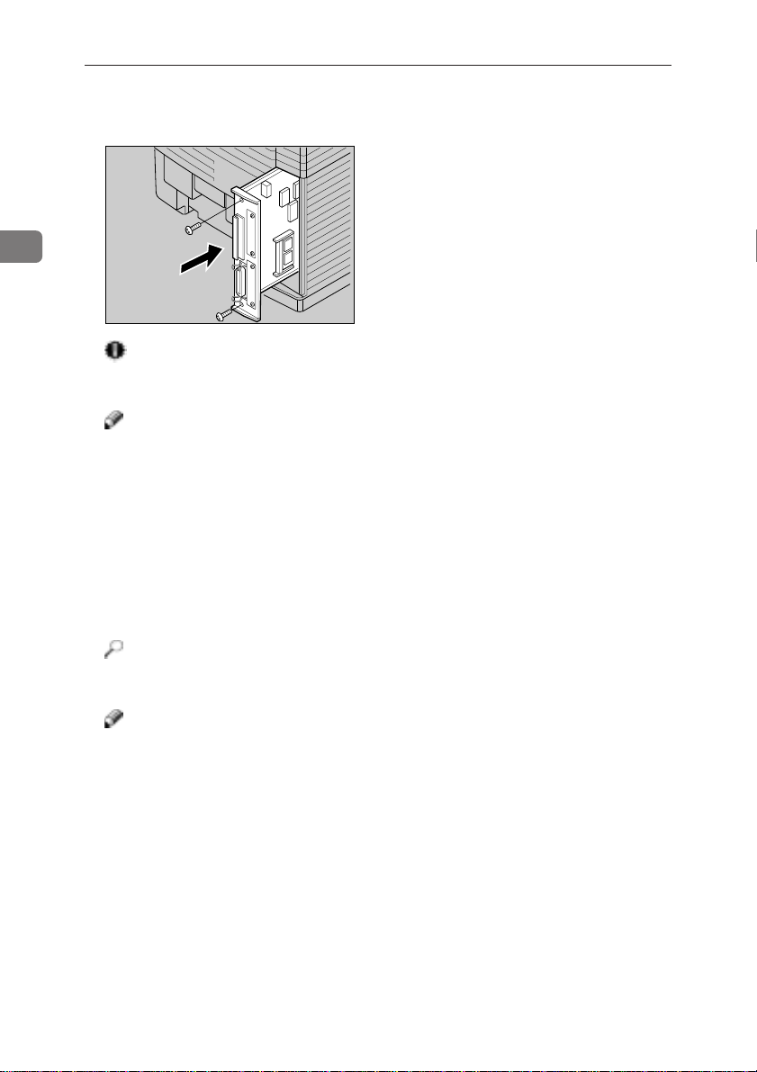
E Insert the network interface board
into the slot and fasten it with both
screws that were removed in step
DD
D, as shown in the illustration.
DD
TPOP180E
2
TPOP130E
Note
❐ A coin can be used to remove the
screws.
13
Page 33
Installing Options
2
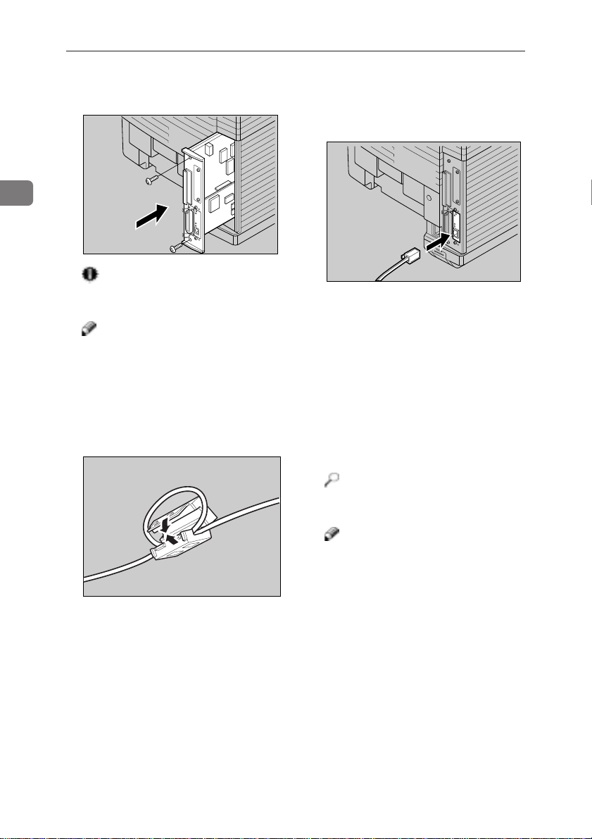
F Insert the printer board into the
printer. Fasten both screws.
Important
❐ Make sure that both screws are
used to secure the printer board.
Note
❐ A coin can be used to fasten the
screws.
G Loop the network interface cable.
The loop should be about 15 cm
(6") from the end of the cable.
H Attach the ferrite core to the loop.
14
TPOP330E
TPOH390E
I Attach the network interface cable
to the network interface connector
of the printer as shown in the illustration.
TPOH440E
J Connect the other end of the net-
work interface cable to the network.
K Plug the printer’s power cord back
into the printer and the wall outlet. Turn on the printer ’s power
switch.
L Print a configuration page to con-
firm that the network interface
board is properly installed.
Reference
❐ => P.101 “Printing the Configura-
tion Page”
Note
❐ You can check if the network in-
terface board is installed properly by checking the “Network”
item of the “Status List” on the
configuration page.
❐ If the network interface board is
not properly installed, repeat the
above steps again. If you fail
again, contact your sales or service representative.
❐ After installing the network in-
terface properly, set up the
printer ’s network environment
using the operation panel. =>
P .23 “Configuring the Printer for the
Network with the Operation Panel”
Page 34
Installing the IEEE 1284 Parallel Type 204
Installing the IEEE 1284 Parallel Type204
Note
❐ The parallel interface board can be
attached to either the front or the
back side of the printer board. This
procedure is for attaching to the
front side.
❐ You cannot install two parallel in-
terface boards at a time.
A Check the contents of the box for
the following items.
• Parallel interface board
• Installation Guide
B T urn off the printer’ s power switch
and remove all cables and cords
from the printer.
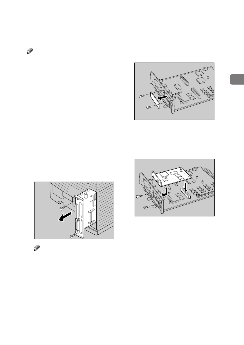
C Remove both screws and remove
the printer board from the printer
as shown in the illustration.
D Remove both screws and the metal
plate from the printer board.
TPOP170E
E Insert the IEEE 1284 Parallel Type
204 board into the slot and fasten
it with both screws that were removed in step
illustration.
DD
D, as shown in the
DD
TPOP180E
2
TPOP130E
Note
❐ A coin can be used to remove the
screws.
15
Page 35
Installing Options
2
F Insert the printer board into the
printer. Fasten both screws.
TPOP330E
Important
❐ Make sure that both screws are
used to secure the printer board.
Note
❐ A coin can be used to fasten the
screws.
G Attach the interface cable to the
parallel interface connector of the
printer. Secure the cable with the
metal fittings as shown in the illustration.
J Print a configuration page to con-
firm that the IEEE 1284 Parallel
Type 204 board is properly installed.
Reference
❐ => P.101 “Printing the Configu-
ration Page”
Note
❐ You can check if the board is in-
stalled properly by checking the
“Option Interface” item of the
“Reference” on the configuration
page.
❐ If the board is not properly in-
stalled, repeat the above steps
again. If you fail again, contact
your sales or service representative.
H Attach the other end of the inter-
face cable to the interface connector of the computer, and secure the
cable.
I Plug the printer’s power cord back
into the printer and the wall outlet. Turn on the printer ’s power
switch.
16
TPOH370E
Page 36

Installing the Paper Feed Unit Type 204
Installing the Paper Feed Unit Type204
R
CAUTION
• It is recommended that at least
two persons are used to lift the
machine. Otherwise, the machine might fall and cause personal injury.
• When lifting the machine, use
the inset grips on both sides of
the machine. Otherwise, the
machine might fall and cause
personal injury.
A Check the contents of the box for
the following items.
• Installation Guide (1 pc)
• Right side cover (1 pc)
• Left side cover (1 pc)
• Screw (2 pcs)
• Securing bracket (2 pcs)
• Paper Feed Unit (1 pc)
B Remove the styrofoam packing [A]
and the bag [B] from the side covers.
[A]
C Remove the bag [C] and the styro-
foam packing [D] from the paper
feed unit.
[D]
[B]
2
TPOP190E
TPOP011E
[C]
TPOP200E
D Remove both pieces of adhesive
tape [E].
[E]
TPOP210E
E Turn off the printer’s power
switch, and remove all cables and
cords from the printer.
17
Page 37

Installing Options
2
F Place the paper feed unit on a flat
surface.
TPOP220E
G Lift the printer using the inset
grips on both sides of the printer.
TPOH110E
Important
❐ It is recommended that at least
two people are used to lift the
printer.
H Align the printer onto the 3 up-
right pins [G] on the paper feed
unit and then lower it gently.
I Insert the securing bracket [H1]
into the rectangular hole on the
right lower side of the printer. Secure the bracket using a screw [I1].
1
2
TPOP252E
[I
1
][H1]
J Insert the securing bracket [H2]
into the rectangular hole on the left
lower side of the printer. Secure
the bracket using a screw [I2].
1
2
[I2][H2]
TPOP242E
K Remove the connector cover [J]
from the printer, and the connector cover [K] from the paper feed
unit.
18
[G]
TPOP230E
[J]
[K]
TPOP280E
Page 38

Installing the Paper Feed Unit Type 204
L Attach the paper feed unit cable to
the socket inside the printer securely.
TPOP290E
M Attach the connector cover [J], re-
moved from the printer in step
to the paper feed unit. Attach the
connector cover [K], removed from
the paper feed unit in step
printer.
[K]
KK
K, to the
KK
N Attach the right side [L] and the
left side [M] covers onto the
printer. When attaching them,
make sure the projections on the
covers are inserted into the rectangular holes on the printer.
[L]
KK
K,
KK
O Connect all of cables that were re-
moved in step
EE
E.
EE
P T urn on the printer’s power switch.
2
[M]
TPOP310E
[J]
TPOP300E
19
Page 39

2
Installing Options
Q Print out the configuration page to
confirm that the paper feed unit is
properly installed.
Reference
❐ => P.101 “Printing the Configura-
tion Page”
Note
❐ If the paper feed unit is properly
installed, you can see “Tray2”
under the “Printer Information”
of the configuration page.
❐ If the paper feed unit does not
work, follow the above instructions to reinstall it. If it still does
not work, contact your sales or
service representative.
Important
❐ To make the printer recognize
the installed option properly,
you must set up the option with
the printer driver. => P.36, 40 or
44 “Setting Up Options”
20
Page 40
Installing the Paper Cassette Type 204
Installing the Paper Cassette Type204
R
CAUTION
• The paper tray does not have a
stopper. When pulling it out, be
careful not to pull it strongly. If
you do, the tray might fall and
cause personal injury.
Note
❐ The standard tray (tray 1) or the tray
of the optional paper feed unit
(tray2) can be replaced with the
Paper Cassette Type204.
A Check the contents of the box for
the following items.
• Paper cassette
• Installation Guide
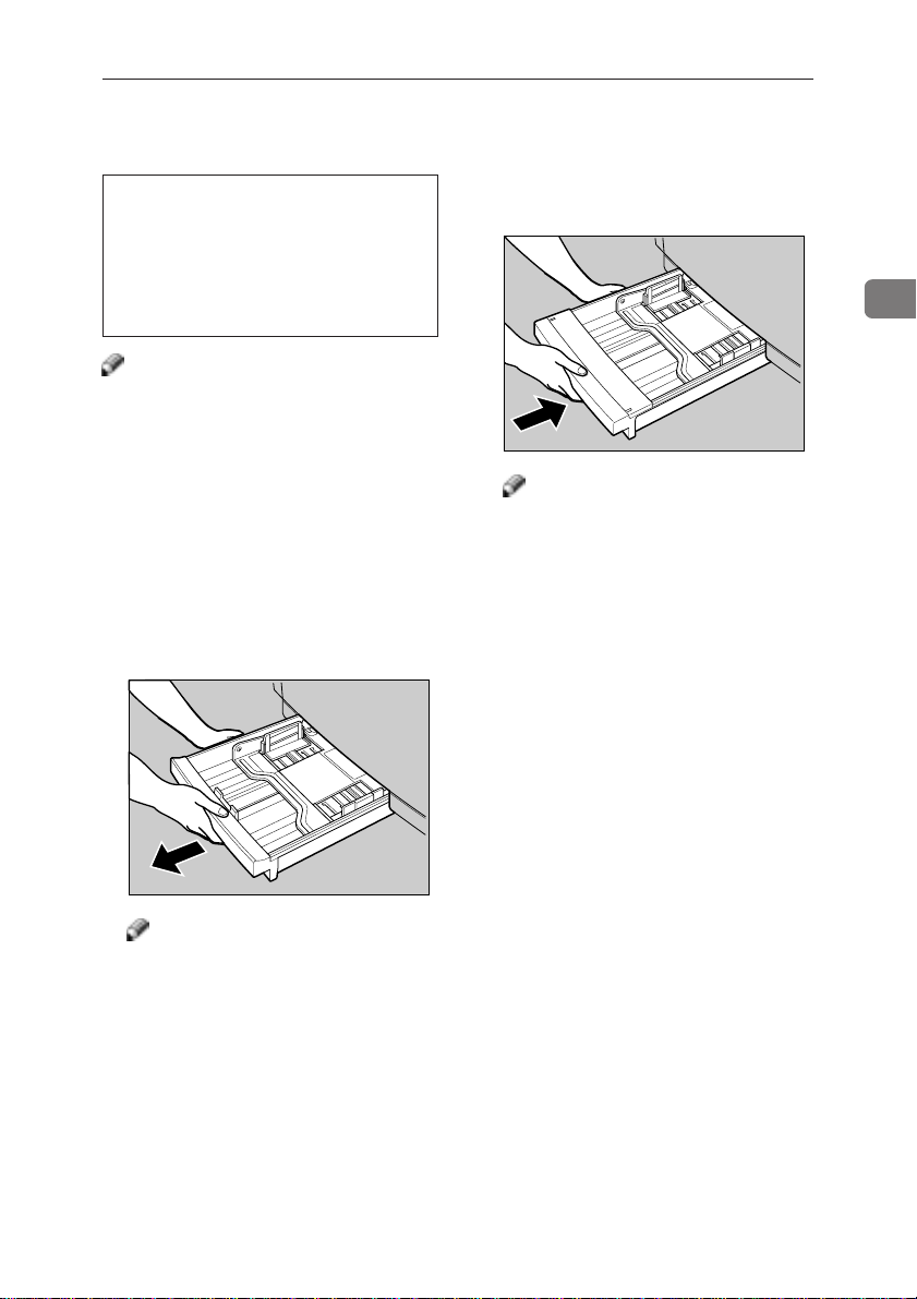
B Carefully pull the paper tray (tray1
or tray2) out of the printer and
place it on a flat surface.
C Slide the Paper Cassette Type 204
completely into the printer.
2
TPOH451E
Note
❐ When loading paper, => P.51
“Loading Paper”
TPOH450E
Note
❐ Keep the paper tray with paper
in a cool and dark place.
21
Page 41

2
Installing Options
22
Page 42

3. Configuring the Printer for the Network
with the Operation Panel
Configuring the Printer for the Network with the Operation Panel
After installing the optional network interface board, configure it for the network using the printer’s operation panel.
Note
❐ If you want to print from your Macintosh computer, the optional RICOH-
SCRIPT 2 Type204 is required.
The following table shows the operation panel settings and their default settings. These are included in the “System Menu”.
Items Default Settings
32 IP Address 011.022.033.044
33 Subnet Mask 000.000.000.000
34 Gateway Add 000.000.000.000
(Gateway Address)
35 Access CTL. 000.000.000.000
(Access Control Address)
36 Access Mask 000.000.000.000
(Access Control Mask)
37 Net Boot None
(Network Boot)
38 Frame NW Auto Select
(Frame type NetWare)
39 Active PTL. All Active
(Active Protocol)
{{
A Press
{
Menu
{{
}}
}.
}}
B Check if the following message appears on the panel display. If not, press
{U} {T}{U} {T}
{U} {T} until the following message appears.
{U} {T}{U} {T}
<Menu> U
System Menu T
{{
C Press
The following message appears.
}}
{
Enter
}.
{{
}}
<System Menu> U
1.Paper Tray T
23
Page 43
3
Setting Up the Printer for Network with the Operation Panel
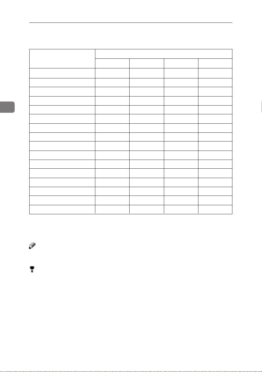
D Select the protocol you want to use. Y ou can select one of items on the table
below .
Menu item on the
panel display
All Active (Default) ✓✓ ✓–
None –
TCP/IP Only ✓ –
NetWare Only ✓ –
TCP & NetWare ✓✓ –
EtherTalk Only ✓ –
TCP & EtherTalk ✓✓–
NetW & EtherTalk ✓✓–
TCP & NW & EtherTK ✓✓ ✓–
NetBEUI Only –
TCP & NetBEUI ✓ –
NetW & NetBEUI ✓ –
TCP & NW & NB ✓✓ –
ETalk & NetBEUI ✓ –
TCP & ETK & NB ✓✓–
NW & ETK & NB ✓✓–
· ✓ means that this protocol is active.
· Blank cell means that this protocol is not active.
· – means that this protocol is not supported.
TCP/IP NetWare EtherTalk NetBEUI *
*1: NetBEUI appears on the panel display, but is not supported.
Note
❐ It is recommended that you should not select protocols that are not used on
your network.
Limitation
❐ If you want to select EtherT alk, you should install the optional RICOH-SCRIPT
2 Type204.
Active Protocol
1
24
Page 44

Setting Up the Printer for Network with the Operation Panel
{U}{U}
1 Press
2 Press
The current setting appears on the panel display.
3 Press
4 Press
{T}{T}
{U}
{T} until the following message appears.
{U}{U}
{T}{T}
<System Menu> U
39.Active PTL.T
{{
}}
{
Enter
}.
{{
}}
<Active PTL.> U
*All Active T
{U}{U}
{T}{T}
{U}
{T} until the protocol you want to use appears.
{U}{U}
{T}{T}
}}
{{
Enter
}.
{
}}
{{
E If you use TCP/IP, you should assign the IP address to your printer.
Note
❐ To get the IP address for your printer, contact your network administrator.
{U}{U}
1 Press
2 Press
The current IP address appears on the panel display.
3 Use
4 Press
The pointer (U) moves to the next digit as shown.
Note
❐ You can return the pointer (U) to the previous (left) digit by pressing {
cape
❐ If you press {
specified IP address is reset.
5 Use
6 Press
7 Repeat steps 5 and 6 to specify the rest digit of IP address.
{T}{T}
{U}
{T} until the following message appears.
{U}{U}
{T}{T}
<System Menu> U
32.IP Address T
}}
{{
Enter
}.
{
}}
{{
011.022.033.044
U
{U} {T}{U} {T}
{U} {T} to specify the leftmost digit of the IP address.
{U} {T}{U} {T}
111.022.033.044
U
{{
}}
{
Enter
}.
{{
}}
111.022.033.044
U
}.
{U} {T}{U} {T}
{U} {T} to specify the second digit of the IP address.
{U} {T}{U} {T}
191.022.033.044
U
{{
}}
{
Enter
}.
{{
}}
191.168.015.016
U
UT/#
UT/#
UT/#
Escape
} when the pointer (U) is on the leftmost position, the
UT/#
3
Es-
25
Page 45

Setting Up the Printer for Network with the Operation Panel
3
8 Check if the pointer (
the IP address you specified.
UU
U) is at the rightmost digit, press
UU
{{
{
Enter
{{
}}
} to register
}}
F If you use TCP/IP , you should assign “33. Subnet Mask”, “34. Gateway Add”,
“35. Access CTL” and “36. Access Mask” using the same procedure for specifying the IP address.
G If you use TCP/IP, you should make settings for “37 Net Boot”. You can
select how to assign the printer’s address using the computer. Select one of
items on the table below.
Menu item on
the panel display
ARP+PING ✓
ARP & RARP ✓✓
ARP & BOOTP ✓✓
ARP & RARP & BOOT ✓✓ ✓
None (Default)
RARP+TFTP ✓
BOOTP ✓
RARP & BOOTP ✓✓
DHCP ✓
Note
❐ Select “None”, if you want to specify the address using the printer’s opera-
tion panel.
❐ You should set up your server , if you want to use “RARP+TFTP”, “BOOTP”,
or “DHCP”.
1 Press
2 Press
3 Press {U} {T} until the method you want to use appears.
4 Press
{U} {T}{U} {T}
{U} {T} until the following message appears.
{U} {T}{U} {T}
<System Menu> U
37.Net Boot T
{{
}}
{
Enter
}.
{{
}}
The current setting appears on the panel display.
<Net Boot> U
*ARP+PING T
}}
{{
Enter
}.
{
}}
{{
ARP+PING RARP+TFTP BOOTP DHCP
Available method
26
Page 46

Setting Up the Printer for Network with the Operation Panel
H If you use NetWare, select the frame type for NetWare. Select one of items
below if necessary.
• Auto Select (Default)
• Ethernet 802.3
• Ethernet 802.2
• Ethernet2
• Ethernet SNAP
Note
❐ Usually, use the default setting (“Auto Select”). However if you select “Auto
Select”, the frame type detected by the printer first is adopted. If your network can use more than two frame types, the printer fails to select the correct frame type, if the “Auto Select” is selected. In this case, select the appropriate frame type.
1 Press
2 Press
3 Press
4 Press
5 Press
{U} {T}{U} {T}
{U} {T} until the following message appears.
{U} {T}{U} {T}
<System Menu> U
38. Frame NW
}}
{{
Enter
}.
{
}}
{{
The current setting appears on the panel display.
<Frame NW> U
*Auto Select T
{U} {T}{U} {T}
{U} {T} until the frame type you want to use appears.
{U} {T}{U} {T}
}}
{{
Enter
}.
{
}}
{{
You have completed the printer’s network settings.
On Line
}}
} .
}}
{{
{
{{
This returns to the normal display screen.
3
I Print the configuration page to check settings you have made.
{{
1 Press
2 Press
<Menu> U
List Print T
3 Press
4 Check if the following message appears. If not, press
following message appears.
<List Print> U
Config.Page T
5 Press
The following message appears.
<Config.Page> U
Press # key T
}}
{
Menu
}.
{{
}}
{U} {T}{U} {T}
{U} {T}, until the following message appears.
{U} {T}{U} {T}
}}
{{
Enter
}.
{
}}
{{
}}
{{
Enter
}.
{
}}
{{
{U} {T}{U} {T}
{U} {T} until the
{U} {T}{U} {T}
27
Page 47
3
Setting Up the Printer for Network with the Operation Panel
{{
6 Press
The configuration page is now printed. Check the contents of the configuration page.
7 Press
The normal display screen appears.
8 Press
The On Line indicator turns off.
9 Press
{
Enter
{{
{{
On Line
{
{{
{{
{
On Line
{{
{{
{
Reset
{{
}}
}.
}}
}}
} .
}}
}}
} to enter the off-line condition.
}}
}}
}.
}}
Address
❖ Subnet Mask
A number used to mathematically “mask” or hide the IP addresses on the
network by eliminating those parts of the address that are alike for all the
machines on the network.
❖ Gateway Address
A gateway is a connection or inter change point that connects two networks. A
gateway address is for the router or host computer used as a gateway.
Note
❐ To get the addresses, contact your network administrator.
❐ If you do not know the addresses, please use the default settings.
Access Control Address and Access Control Mask
Access Control Address and Access Control Mask are used to control the IP addresses that have access to the computer used for printing, with the IP address. If
it is not necessary for you to control the access right, select “0.0.0.0”.
Note
❐ When the setting of Access Control Addr ess coincides with the masked r esult
of the IP address of the computer, print jobs from that IP address can be accepted by the network interface board.
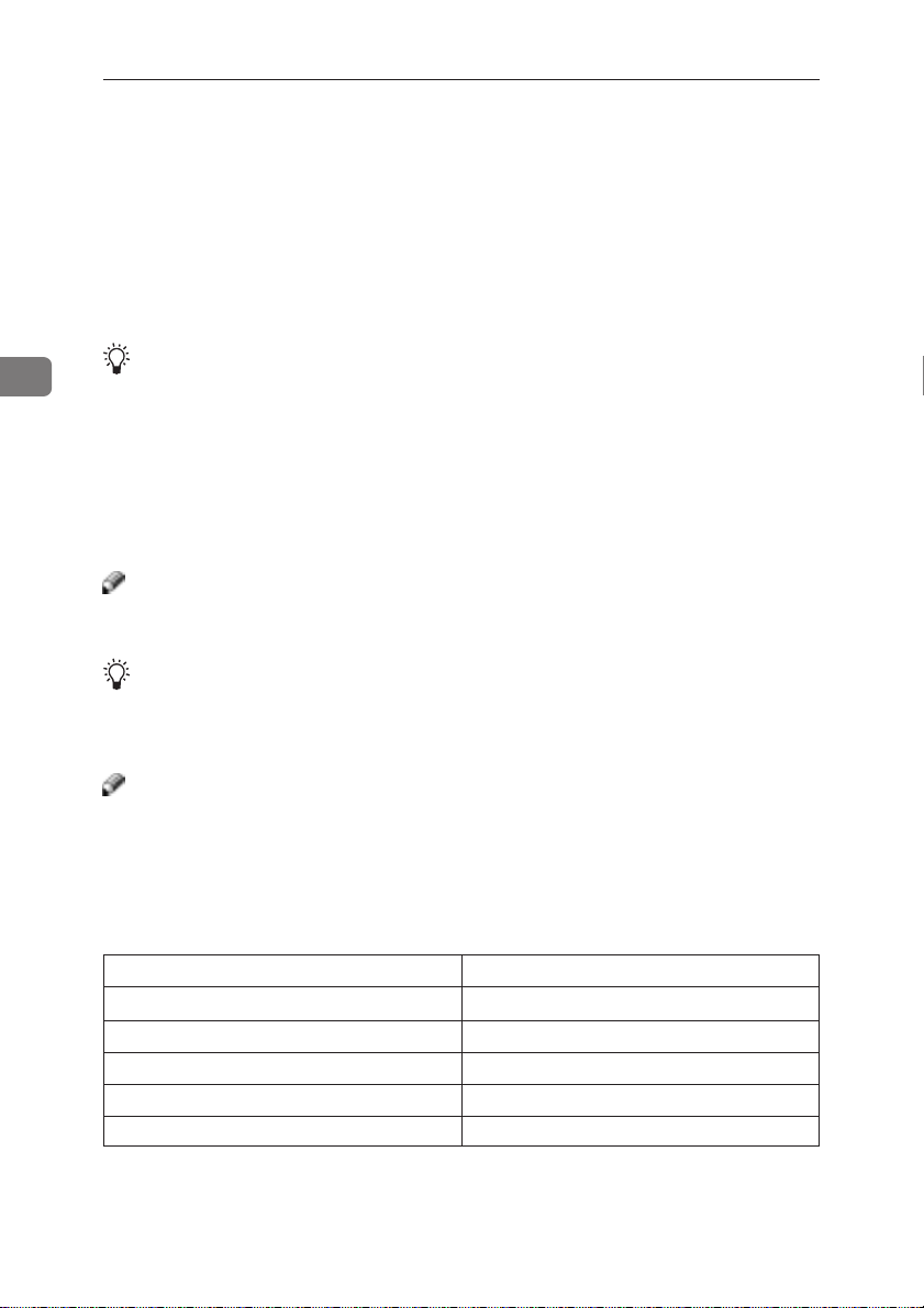
❐ For example, if you assign 192.168.15.16 as the Access Control Address to the
network interface board, the combination of the Access Control Mask and IP
address that can have access are as follows.
Access Control Mask IP Address that have access
0. 0. 0. 0 xxx.xxx.xxx.xxx
255. 0. 0. 0 192.xxx.xxx.xxx
255.255. 0. 0 192.168.xxx.xxx
255.255.255. 0 192.168. 15.xxx
255.255.255.255 192.168. 15. 16
28
Page 48

4. Installing the IPDL-C Printer
Driver
Before Installing the Printer Drivers
T o print, you must first install software called a printer driver on your computer.
The required printer driver is supplied on the CD-ROM that comes with your
printer.
Preparation
❐ Set up the printer and connect it to your computer as described in the “Quick
Installation Guide”.
❐ The procedures in this section assume that the printer is connected to your
printer by a parallel interface cable.
Important
❐ Some applications require their own specific settings, which may be differ ent
from those provided by the printer driver . Be sure to check the documentation
that comes with your applications for details.
❐ Considerable hard disk space is required on your computer for printing com-
plex documents.
Note
❐ All of the procedures in this manual assume that you are familiar with general
Windows procedur es and practices. If you are not, see the documentation that
comes with Windows for details.
Installing the Printer Drivers
Limitation
❐ The printer drivers supplied with this printer do not support operation
under a system running Windows NT
R Series, Alpha AXP, Power PC).
Note
❐ Recommended PC requirements:
• Memory: 32MB or more
• CPU: Pentium
• Free Hard disk space: 100MB or more
❖
Supported Operating Systems
❐ Microsoft® Windows® 95 operating system
❐ Microsoft
❐ Microsoft
❐ Microsoft
❐ Microsoft
®
100Mhz or more
®
Windows® 98 operating system
®
Windows® for Workgroups operating system 3.1x
®
WindowsNT® Server network operating system Version4.0
®
WindowsNT® W orkstation Network operating system V ersion4.0
®
with a RISC based processor (MIPS
29
Page 49

4
Installing the IPDL-C Printer Driver
Windows 95/98 - Installing the IPDL-C Printer Driver
Preparation
❐ Before starting installation, be sure to carefully read the README file that is
on the CD-ROM containing the printer driver.
Important
❐ Never have two versions of the same printer driver installed on your system
at the same time. When upgrading to a new version of the printer driver, delete the old version, and then install the new one.
Normally you can use plug and play to install the printer driver . If your system does
not support plug and play, add the printer from the [Printers] window.
❖
Plug and Play
Plug and play automatically makes the required software settings whenever
it detects that a new peripheral device has been connected to the computer.
Plug and Play operates when the following conditions are present.
• The computer supports plug and play (see the computer’s documentation
for details).
• The printer is connected to the computer by a bi-directional interface cable.
• Printer power is turned on first, and then the computer is turned on.
30
Printer Driver Installation Flow
Read the
README
file.
Install the
Turn on
the
printer.
Turn on
the
computer.
driver in accordance with the
instructions
that appear on
your computer
screen.
If the
[New Hardware Found]
☞ P.32 “Plug and Play Installation 1”
[Device Driver Wizard]
If the
☞ P.33 “Plug and Play Installation 2”
If Windows 95/98 starts normally.
☞ P.34 “Installing the Printer Driver With-
out Using Plug and Play”
dialog appears.
appears.
Page 50
Windows 95/98 - Installing the IPDL-C Printer Driver
Installing the Printer Driver Using Plug and Play
Preparation
❐ Check to make sure that the printer is connected properly to your computer,
and that computer power is turned off.
A Turn on the printer.
B Turn on your computer.
Continue with one of the procedures below in accordance with what appears
on your computer’s screen.
Note
❐ What happens after you turn on your computer depends on which version
of Windows 95/98 you are running and on your system setup.
When the [New Hardware Found] dialog appears
This dialog indicates that plug and play is working. Continue with the procedure under “Plug and Play Installation 1” on page 32.
When the [Device Driver Wizard] appears
This indicates that plug and play is working. Continue with the procedure under
“Plug and Play Installation 2” on page 33.
4
When Widows 95/98 starts normally
This indicates that plug and play is not working. Continue with the procedure
under “Installing the Printer Driver Without Using Plug and Play” on page 34.
31
Page 51

Installing the IPDL-C Printer Driver
Plug and Play Installation 1
4
Use the following procedure to install the printer when the
dialog appears after you turn on the printer and then your computer.
[New Hardware Found]
A Insert the CD-ROM that comes with the printer, into your computer’s CD-
ROM drive.
B Click
C Select the CD-ROM drive using the
D In the Folders box, double-click
E Click
[Browse]
The Windows 95/98 printer driver is on the following directory on the CDROM:DRIVERS\IPDL_C\WIN95_98.
nally, click
[OK]
The installer copies the printer driver files from the CD-ROM to your
computer’s hard disk.
.
.
[OK]
[Drives]
[DRIVERS], [IPDL_C]
.
list box.
and then
[WIN95_98]
. Fi-
F Restart Windows after completing the installation.
Important
❐ If your printer is equipped with certain options (ex. paper feed unit or
memory unit), you should set up the options with the printer driver.
=> P.36 “Setting Up Options”
32
Page 52

Plug and Play Installation 2
Windows 95/98 - Installing the IPDL-C Printer Driver
Use the following procedure to install the printer when the
appears after you turn on the printer and then your computer.
[Device Driver Wizard]
A Insert the CD-ROM that comes with the printer into your computer’s CD-
[Next]
ROM drive, and then click
B Click
[Finish]
.
C Change the name of the printer, if you want, and then click
D If the next dialog appears, click
.
[OK]
[Finish]
.
.
E If the next dialog asking you to specify the CD-ROM drive appears, select
the CD-ROM drive from the listbox. Finally, click
[OK]
.
F Follow the instructions on the screen.
G Restart Windows after completing the installation.
Important
❐ If your printer is equipped with certain options (ex. paper feed unit or
memoryunit), you should set up the options with the printer driver.
=> P.36 “Setting Up Options”
4
33
Page 53

Installing the IPDL-C Printer Driver
Installing the Printer Driver Without Using Plug and Play
Turn on the printer and then your computer, and then use the following procedure to install the printer driver.
A Close all applications that are currently running.
4
B Click
C Double-click the
D Click
E After confirming that the
F Click
[Start]
, point to
The
[Printers]
The Add Printer Wizard appears.
A dialog for specifying the port where the printer is connected appears.
A dialog for selecting the printer manufacturer and model name appears.
A dialog for driver installation from a disk appears.
window appears.
[Next]
.
[Have Disk]
[Settings]
[Add Printer]
.
, and then click
icon.
[Local Printer]
option is selected, click
[Printers]
.
[Next]
.
G Insert the CD-ROM that comes with the printer into your computer’s CD-
ROM drive.
H Click
I Use the
J In the
K Click
[Browse]
The Windows 95/98 printer driver is on the following directory on the CDROM: DRIVERS\IPDL_C\WIN95_98.
nally, click
[OK]
A port selection dialog appears.
.
[Drives]
[Folders]
[OK]
.
listbox to select the CD-ROM drive.
box, double-click
.
[DRIVERS], [IPDL_C]
and then
[WIN95_98]
. Fi-
L Select the name of the printer whose driver you want to install by clicking
[Next]
.
box, select
[Printer Port]
by clicking it, and then click
34
it, and then click
A port selection dialog appears.
M In the
[Available Ports]
[Next]
.
A dialog for changing the printer name appears.
Page 54

Windows 95/98 - Installing the IPDL-C Printer Driver
N Change the name of the printer if you want, and then click
O Specify whether or not you want to print a test page, and then click
The printer driver files are copied from the CD-ROM to your computer’s hard
disk.
P If you are asked if you restart Windows, select
restart Windows after completing the installation.
[Yes]
[Next]
.
[Finish]
. If you are not asked,
Q After Windows restarts, set up any options you have installed on the printer .
Reference
❐ => P.36 “Setting Up Options”.
.
4
35
Page 55

Installing the IPDL-C Printer Driver
Setting Up Options
4
A Click
The
[Start]
[Printers]
, point to
window appears.
[Settings]
, and then click
[Printers]
.
B Select the icon of the printer you want to use by clicking it. On the
menu, click
C Click
The
[Installable Options]
D Use the
Specifying the wrong tray here will make it impossible to install your tray
correctly.
E Use the
on the printer.
Specifying the wrong amount of memory here may cause printing problems.
Be sure to change this setting whenever you add more memory.
Reference
❐ Y ou can find out how much memory is currently stor ed in memory by print-
ing a Configuration Page on the printer . => P.101 “Printing the Configuration
Page”.
F Click
G Click
[Properties]
[Setup]
tab, and then click
[Option Tray]
[T otal Printer Memory]
[OK]
to close the dialog.
[OK]
to close the printer’s Properties dialog.
.
[Installable Options]
dialog appears.
listbox, to specify the optional tray unit.
listbox to specify how much memory is installed
.
[File]
36
Page 56

Windows 95/98 - Installing the IPDL-C Printer Driver
Canceling a Print Job
A Double-click the printer icon on the Windows Task Bar.
This opens a window that shows all the print jobs that are currently queued
for printing. Check the current status of the job you want to cancel.
B Select the name of the job you want to cancel by clicking it.
C On the
❐ You can also open the print job queue window by double-clicking the printer
[Document]
Note
icon in the
menu, click
[Printer]
window.
[Cancel Printing
].
D Make sure that the printer’s On Line indicator is lit, press the printer’s
}}
set
}
key .
}}
The message appears on the operation panel display indicating that the print
job is being cancelled.
Important
❐ The above procedure cancels the print job that is currently being processed
by the printer. In some cases, the printer may already be processing data
for the next print job following the one currently being output. In such a
Reset
case, the next print job is also canceled when you press {
❐ When your printer is being shared by multiple computers, be careful you
don’t accidentally cancels someone else’s print job.
Note
❐ You cannot stop printing data that has already been processed internally
by the printer. Because of this, printing may continue for a few pages after
you press {
❐ A print job that contains a large volume of data may take a considerable
time to stop.
Reset
}.
}.
{{
{
{{
Re-
4
37
Page 57

Installing the IPDL-C Printer Driver
Windows 3.1x - Installing the IPDL-C Printer Driver
Preparation
❐ Before starting installation, be sure to carefully read the README file that is
on the CD-ROM containing the printer driver.
Important
❐ Never have two versions of the same printer driver installed on your system
at the same time. When upgrading to a new printer driver version, uninstall
the old version, and then install the new one.
4
Installing the Printer Driver
A From the Program Manager
click the
The
B Click
If there are no printers installed on your computer, the
automatically when you display the
grayed out. If this is the case, perform the next step, below.
C In the
and then click
The
[Printers]
[Printers]
[Add]
[List of Printers]
[Install Drivers]
icon.
dialog appears.
to expand the dialog and display the
[Install…]
dialog appears.
, select
.
[Main]
group, open the
[Printers]
[Install Unlisted or Updated Printer]
[Control Panel]
[List of Printers]
[List of Printers]
dialog, and the
.
[Add]
by clicking it,
and double-
appears
button is
D Insert the CD-ROM that comes with the printer into your computer’s CD-
ROM drive.
E Click
[Browse…]
The Windows 3.1x printer driver is on the following directory on the CDROM:DRIVERS \IPDL_C\WIN31.
.
F Use the Drives listbox to select the CD-ROM drive.
G In the
H Click
[Directories]
nally, click
[OK]
.
box, double-click
[OK]
.
[DRIVERS], [IPDL_C]
and then
[WIN31]
. Fi-
38
I In the
[List of Printers]
want to install by clicking it, and then click
The printer driver files are copied from the CD-ROM to your computer’s hard
disk.
box, select the name of the printer whose driver you
[OK]
.
Page 58

Windows 3.1x - Installing the IPDL-C Printer Driver
J After installation is complete, click
[Close]
to close the
[Printers]
dialog.
K Restart Windows.
L After Windows restarts, setup any options you have installed on the printer .
Reference
❐ => P.40 “Setting Up Options”.
4
39
Page 59

Installing the IPDL-C Printer Driver
Setting Up Options
4
A From the Program Manager
click the
The
B In the
by clicking on it, and then click
A dialog for making printer driver settings appears.
C Click
The
D Use the
Specifying the wrong tray here will make it impossible to install your tray
correctly.
E Use the
on the printer.
Specifying the wrong amount of memory here may cause printing problems.
Be sure to change this setting whenever you add more memory.
❐ Y ou can find out how much memory is currently stor ed in memory by print-
F Click
G Click
[Printers]
[Printers]
[Installed Printers]
[Setup]
[Installable Options]
[Option Tray]
[T otal Printer Memory]
Reference
ing a Configuration Page on the printer . => P.101 “Printing the Configuration
Page”
[OK]
to close the dialog.
[OK]
to close the dialog.
icon.
dialog appears.
tab, and then click
dialog appears.
listbox, to specify the optional tray unit.
[Main]
group, open the
box, select the name of the printer you want to use
[Setup…]
[Installable Options]
listbox to specify how much memory is installed
.
[Control Panel]
.
and double-
40
H Click
[Close]
to close the
[Printers]
dialog.
Page 60

Canceling a Print Job
Windows 3.1x - Installing the IPDL-C Printer Driver
A In the
[Main]
group, double-click the
A window that shows all the print jobs that ar e curr ently queued for printing
appears.
[Print Manager]
icon.
B Select the name of the job you want to cancel by clicking it.
C On the
D Click
E Click
[Document]
[Close]
to close the dialog.
[Close]
to close the dialog.
menu, click
[Delete Document]
.
F Make sure that the printer’s On Line indicator is lit, press the printer’s
}}
}
key .
set
}}
The message appears on the operation panel display indicating that the print
job is being cancelled.
Important
❐ The above procedure cancels the print job that is currently being processed
by the printer. In some cases, the printer may already be processing data
for the next print job following the one currently being output. In such a
case, the next print job is also canceled when you press {
❐ When your printer is being shared by multiple computers, be careful you
don’t accidentally cancels someone else’s print job.
Note
❐ You cannot stop printing data that has already been processed internally
by the printer. Because of this, printing may continue for a few pages after
Reset
you press {
❐ A print job that contains a large volume of data may take a considerable
time to stop.
}.
Reset
}.
{{
{
{{
Re-
4
41
Page 61

4
Installing the IPDL-C Printer Driver
Windows NT4.0 - Installing the IPDL-C Printer Driver
Preparation
❐ Before starting installation, be sure to carefully read the README file that is
on the CD-ROM containing the printer driver.
Important
❐ Never have two versions of the same printer driver installed on your system
at the same time. When upgrading to a new printer driver version, uninstall
the old version, and then install the new one.
Limitation
❐ Printer driver installation requires full control access rights. To install the printer
driver, log on as an Administrators or Power Users group member.
Installing the Printer Driver
A Click
B Double-click the
C After Confirming that
D Click a check box to select the port you want to use, and click
E Click
[Start]
, point to
[Printers]
The
The Add Printer Wizard appears.
A dialog for specifying the port where the printer is connected appears.
A dialog for the manufacturer and model of the printer appears.
A dialog for driver installation from a disk appears.
window appears.
[Have Disk…]
[Settings]
[Add Printer]
.
icon.
[My Computer]
, and then click
option is selected, click
[Printers]
.
[Next]
.
[Next]
.
F Insert the CD-ROM that comes with the printer into your computer’s CD-
ROM drive.
G Change the drive name in the listbox to the name of the CD-ROM drive,
and then click
The Windows NT4.0 printer driver is on the following directory on the CDROM:DRIVERS\IPDL_C\NT4.
H Double-click
I Click
[OK]
A printer model selection dialog appears.
[Browse…]
[DRIVERS], [IPDL_C]
.
.
and then
[NT4]
. Finally, click
[Open]
.
42
Page 62

Windows NT4.0 - Installing the IPDL-C Printer Driver
J Select the name of the printer whose driver you want to install by clicking
it, and then click
A dialog for changing the printer name appears.
[Next]
.
K Change the name of the printer if you want, and then click
L If the printer is to be shared over a network, click
[Shared]
Selecting
server. If you select
M In the
N Click
[Shared Name]
network.
The initial default Shared name is the same name as the Name box in step
above. You can leave this name as it is, or change to a different one.
[Next]
causes the computer you are on to operate as the printer
[Not shared]
box, type in the name that printer should use on the
.
here, skip step
MM
M
MM
[Shared]
.
O Specify whether or not you want to print a test page, and then click
The printer driver files are copied from the CD-ROM to your computer’s hard
disk.
After installation is complete, the
the newly installed printer.
[Printers]
window appears with the icon of
[Next]
.
to select it.
KK
K
KK
[Finish]
P Restart Windows.
Q After Windows restarts, set up any options you have installed on the printer .
Reference
❐ => P.44 “Setting Up Options”.
,
4
.
43
Page 63

Installing the IPDL-C Printer Driver
Setting Up Options
4
A Click
The
[Start]
[Printers]
, point to
window appears.
[Settings]
, and then click
[Printers]
.
B Select the icon of the printer you want to use by clicking it. On the
menu, click
The printer properties dialog appears.
C Click the
D Use the
Specifying the wrong tray here will make it impossible to install your tray
correctly.
E Use the
on the printer.
Specifying the wrong amount of memory here may cause printing problems.
Be sure to change this setting whenever you add more memory.
Reference
❐ Y ou can find out how much memory is currently stor ed in memory by print-
ing a Configuration Page on the printer . => P.101 “Printing the Configuration
Page”
F Click
[Properties]
[Installable Options]
[Option Tray]
[T otal Printer Memory]
[OK]
to close the printer properties.
.
tab.
listbox, to specify the optional tray unit.
listbox to specify how much memory is installed
[File]
44
Page 64

Windows NT4.0 - Installing the IPDL-C Printer Driver
Canceling a Print Job
A Double-click the printer icon on the Windows Task Bar.
A window that shows all the print jobs that ar e curr ently queued for printing
appears. Check the current status of the job you want to cancel.
B Select the name of the job you want to cancel by clicking it.
C On the
❐ You can also open the print job queue window by double-clicking the printer
[Document]
Note
icon in the
menu, click
[Printer]
window.
[Cancel Printing]
.
D Make sure that the printer’s On Line indicator is lit, press the printer’s
}}
set
}
key .
}}
The message appears on the operation panel display indicating that the print
job is being cancelled.
Important
❐ The above procedure cancels the print job that is currently being processed
by the printer. In some cases, the printer may already be processing data
for the next print job following the one currently being output. In such a
Reset
case, the next print job is also canceled when you press {
❐ When your printer is being shared by multiple computers, be careful you
don’t accidentally cancels someone else’s print job.
Note
❐ You cannot stop printing data that has already been processed internally
by the printer. Because of this, printing may continue for a few pages after
you press {
❐ A print job that contains a large volume of data may take a considerable
time to stop.
Reset
}.
}.
{{
{
{{
Re-
4
45
Page 65

4
Installing the IPDL-C Printer Driver
46
Page 66
5. Paper and Other Media
Paper and Other Media Supported by this Printer
Paper Types and Sizes
The following tables show the type, size, and feed direction of paper that can be
loaded in the printer ’s paper trays. They also show the maximum number of
sheets that can be loaded.
Note
❐ The “K” symbol means short-edge feed direction.
❐ This printer supports short-edge feed direction (K) only.
The supported paper size varies depending on the amount of memory in your
printer. => P107 “Memory Capacity and Paper Size”
❖
Standard Paper Tray
Paper Size
A4K(210 × 297 mm), JIS B5K(182 × 257 mm), 250 sheets
1
/2" × 11" K(Letter), 71/4" × 101/2" K (Executive)
8
Custom size*2 (Length: 210 to 297 mm, Width: 100 to 216 mm)
*1: Based on paper that is 80 g/m2 (metric version), 20 lb (inch version) in weight.
*2: You should specify the paper size with the printer driver and operation panel.
❖
Optional 250-sheet Paper Tray (Paper Feed Unit Type204)
Paper Size
A4K(210 × 297 mm), JIS B5K(182 × 257 mm), 250 sheets
1
/2" × 11" K(Letter), 71/4" × 101/2" K (Executive)
8
*1: Based on paper that is 80 g/m2 (metric version), 20 lb (inch version) in weight.
❖
Optional Paper Tray (Paper Cassette Type204*1)
Paper Size
A4K(210 × 297 mm), JIS B5K(182 × 257 mm), 81/2" × 11"K(Letter), 250 sheets
1
/4" × 101/2" K (Executive), 81/2" × 14" K(Legal)
7
Custom size*
*1: This tray can be replaced with both the standard tray (tray 1) and the tray of the optional paper feed
unit.
*2:
You can load the custom paper size only when you replace this tray with the tray 1.
*3: You should specify the paper size with the printer driver and operation panel.
*4: Based on paper that is 80 g/m
2, 3
(Length: 210 to 356 mm, Width: 100 to 216 mm)
2
(metric version), 20 lb (inch version) in weight.
Maximum number of
sheets to be set*
Maximum number of
sheets to be set*
Maximum number of
sheets to be set*
1
1
4
47
Page 67

Paper and Other Media
Precautions for Paper
Note the following precautions when handling or selecting paper to be used
with this printer.
Cautions in loading paper
❐ Use only the recommended paper types. Print quality cannot be guaranteed if
other paper types are used.
❐ Do not use paper that is already printed on.
❐ When loading paper into the paper tray, make sure that the top of the stack is
not higher than the limit mark inside the tray.
❐ When loading paper into the paper tray , make sur e that the print side is facing
up.
5
Cautions in storing paper
Paper should always be stored properly. Improperly stored paper might damege
the paper, resulting in poor print quality, paper misfeeds, or printer damage.
Follow the precautions below.
• Avoid storing paper in humid areas.
• Avoid exposing paper to direct sunlight.
• Store on a flat surface.
• Keep open reams of paper in the package in which the paper came.
Paper types and cautions
❖
Plain Paper
❐ The paper tray can support paper 60 - 162 g/m2 (16 - 43 lb) in weight.
❐ If you print on the paper heavier than 90 g/m
thick paper mode with the printer driver.
❐ If paper is curled or bent, correct it before loading.
❖
Thick Paper
❐ Printing is supported on thick paper up to 160g/m2 (43 lb). The print quality
on paper that is thicker cannot be guaranteed.
❐ Make sure that the stack of paper is no higher than the LABEL upper limit
T) inside the tray.
mark (
2
(24 lb), you should select the
48
Page 68

Paper Supported by This Printer
❖
Adhesive Labels
❐ Load adhesive labels into the tray with the print side up.
❐ Remove any unused adhesive labels from the tray after you are finished print-
ing. Leaving them in the tray can cause them to curl.
❐ The paper tray can hold up to 30 adhesive labels. Make sure that the stack of
paper is no higher than the LABEL upper limit mark (
❐ Use adhesive labels which can be printed on the whole side.
❐ Avoid using the adhesive labels on which glue is exposed.
❐ If the print side is coated, the print quality might be reduced, as the toner
might fuse well.
❐ When printing on adhesive labels, you should select the thick paper mode
with the printer driver.
❖
OHP Transparencies
❐ When printing on an OHP transparency that has a print side, load it face up in
the paper tray.
❐ When printing on an OHP transparency that has tape on it, load it in the pa-
per tray so that the edge with tape is the trailing edge.
❐ When printing on the OHP transparencies, you should select the OHP trans-
parency mode with the printer driver.
❐ Remove any unused OHP transparencies from the tray after you ar e finished
printing. Leaving them in the tray can cause them to curl.
❐ The paper tray can hold up to 50 OHP transparency sheets. Make sure that the
stack of paper is no higher than the OHP upper limit mark (
❐ Be careful not to touch the print side of the OHP transparencies. Otherwise,
the print side may be dirty or damaged, resulting in poor print quality.
T) inside the tray.
T) inside the tray.
5
Paper not supported by this printer
❐ A void using the following types of paper that are not supported by this printer .
• Paper whose weight is heavier or lighter than the limitation
• Bent, folded, or creased paper
• Curled or twisted paper
• Torn paper
• Wrinkled paper
• Damp paper
• Papers that are stuck together
• Paper that is dry enough to emit static electricity
49
Page 69

5
Paper and Other Media
• Paper that has already been printed on (with the exception of preprinted
letterhead)
Note
❐ The ink used for the former printing by a copier , or an inkjet printer and so on
might do harm to the fusing unit of this printer due to a difference in fusing
temperatures.
• Coated paper (except the recommended one)
• Special paper like thermal paper, aluminum foil, carbon paper and conductive paper
• Heavily textured paper
• Glued paper
• Label paper on which glue or base paper is exposed
• Paper with clips or staples
• Paper with tape or ribbons attached
• Postcards
Printable Area
The following shows the printable area for this printer. Be sure to set the print
margins correctly.
Feed direction
1
4.3 mm ( /6") 4.3 mm ( /6")
1
1
4.3 mm ( /
6")
printable area
1
6")
4.3 mm ( /
Note
❐ The printable area may vary depending on paper size, printer language and
printer driver settings.
50
Page 70
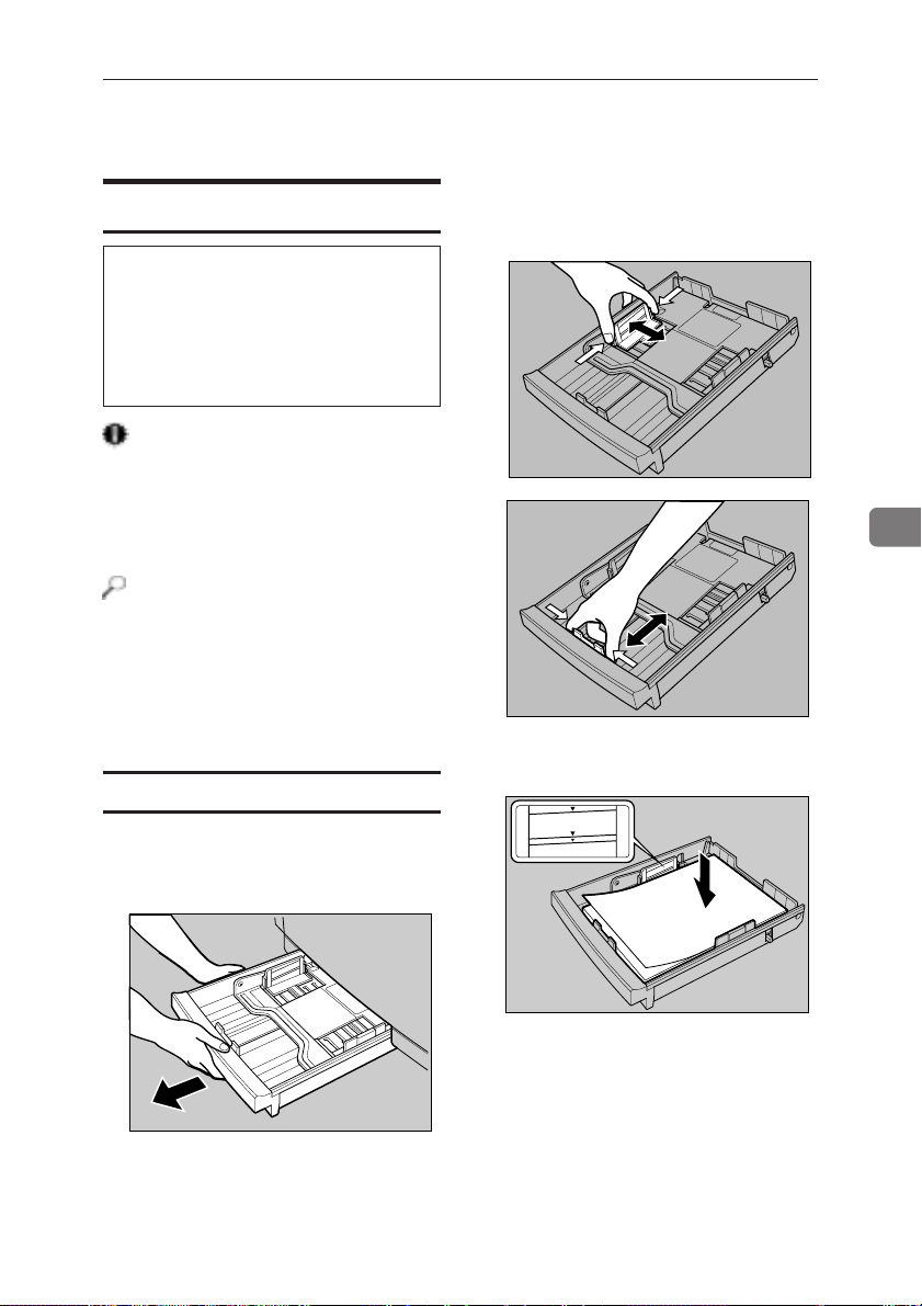
Loading Paper
Loading Paper
Loading Paper in the Paper T ray
R
CAUTION
• The paper tray does not have a
stopper. When pulling it out, be
careful not to pull it strongly. If
you do, the tray might fall and
cause a personal injury.
Important
❐ After you load paper, you must use
the printer driver’s
[Option Setup]
tab
to specify the paper size for the
computer to be able to know what
size is loaded.
Reference
❐ See “Paper Types and Sizes” on
page 47 for details on supported paper types and sizes.
❐ Custom size paper is supported by
the standard paper tray (Tray 1)
only.
Loading paper
A Carefully pull the paper tray out
of the printer and place it on a flat
surface.
B Slide the paper guides to positions
that match the size of paper you
want to load.
TPOH300E
TPOH301E
C Load paper into the tray with the
print side up.
PAPER
LABEL
ENVEL OPE
OHP FILM
5
TPOH450E
TPOH310E
51
Page 71
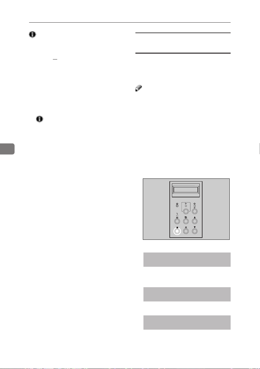
Paper and Other Media
5
Important
❐ Make sure that the stack of paper is
no higher than the top-most limit
T) inside the tray.
mark (
❐ The front and side guides should be
set to the correct paper size to avoid
paper feed problems.
❐ Do not load different kinds of pa-
per in the tray at a time.
D Slide the paper tray completely
into the printer.
Important
❐ Be sure to insert the paper tray
completely. Otherwise, paper
misfeeds might occur, or the
front cover might touch the paper tray.
Specifying paper size using the
operation panel
Use the following procedure to specify
the paper size from the printer’s operation panel after loading custom size
paper into the standard paper tray.
Note
❐ Y ou can set the custom paper in the
standard tray (tray 1) only.
❐ To switch to the tray 1, => P54
“Switching between Paper Trays”.
❐ The custom paper size setting is
cleared when the printer is turned
off.
❐ After pressing a key, wait until the
display changes as described before
performing the next key operation.
{{
A Press
{
Media
{{
}}
}.
}}
52
The “Media” menu appears.
<Media> U
1.Paper Tray T
{U}{U}
B Use
{U} and
{U}{U}
per Size,” and then press
The “Paper Size” menu appears.
{T}{T}
{T} to display “2. Pa-
{T}{T}
<Media> U
2.Paper Size T
<Paper Size> U
*Auto Detect T
{{
{
Enter
{{
TPOS050G
}}
}.
}}
Page 72

Loading Paper
{U}{U}
C Use
{U} and
{U}{U}
tom,” and then press
This following message appears.
D Use
{U}{U}
{U} and
{U}{U}
third (leftmost) digit of the paper
width.
{T}{T}
{T} to display “Cus-
{T}{T}
{{
Enter
{
{{
<Custom>
UT/# Width 140mm
<Custom>
UT/# Width 140mm
T
{T}{T}
{T} to change the
{T}{T}
T
}}
}.
}}
E When the third digit is the value
}}
{{
Enter
you want, press
TT
T pointer to the second digit.
TT
<Custom>
UT/# Width 140mm
Note
❐ You can press {
the pointer to the left.
{U} {T}{U} {T}
F Use
{U} {T} to change the second
{U} {T}{U} {T}
(center) digit of the paper width.
<Custom>
UT/# Width 120mm
{
{{
Escape
} to move the
}}
T
} to move
T
J While the
the first (rightmost) digit of the
length, press
The “Paper Size” menu appears.
K Press
The normal display screen appears.
Note
❐ To change back from the “Cus-
tom” size setting to automatic
paper size detection, use {U} and
{T} in step
cedure to scroll to “Auto Detect”,
and then press {
TT
T pointer is located at
TT
}}
{{
Enter
}.
{
}}
{{
{{
{
{{
On Line
}}
}.
}}
CC
of the above pro-
C
CC
Enter
}.
5
G Repeat steps E and F to set the
value of the first (rightmost) digit
of the width.
H While the pointer is located at the
first digit (rightmost) of the width,
}}
{{
Enter
press
length setting display.
} to advance to the
{
}}
{{
<Custom>
UT/# Length216mm
T
I Use the same procedure as that for
the width to set the three length digits. Move the
{{
Escape
with
{
{{
{{
}}
{
Enter
}. Use
{{
}}
the digit where the pointer is located.
TT
T pointer to the left
TT
}}
} and to the right with
}}
{U}{U}
{U} and
{U}{U}
{T}{T}
{T} to change
{T}{T}
53
Page 73

5
Paper and Other Media
Switching between Paper T rays
You can use the following procedure
to switch between paper feed when the
optional paper feed unit is installed on
the printer .
❐ The paper tray you specify in the
following procedure is cleared
when the printer is turned off.
AA
A
AA
{{
Press
The “Media” menu appears.
}}
{
Media
}.
{{
}}
<Media> U
1.Paper Tray T
TPOS050G
CC
{U}{U}
Use
{U} and
C
{U}{U}
CC
(paper size)”, and then press
}}
ter
}.
}}
This selects the optional tray unit
and the “Media” menu appears.
DD
Press
D
DD
The normal display screen appears.
Note
❐ To return the setting to the stan-
dard tray, select “Tray 1/ (paper
size)” in step 3 of the above procedure.
{T}{T}
{T} to display “T ray2/
{T}{T}
{{
{
{{
On Line
}}
}.
}}
{{
{
{{
En-
54
BB
After confirming that “1. Paper
B
BB
Tray” is on the display, press
}}
{{
Enter
}.
{
}}
{{
The Paper Tray menu appears.
• Metric version
<Paper Tray> U
*Tray1/A4 T
• Inch version
<Paper Tray> U
*Tray1/LT T
Note
❐ An asterisk (*) indicates the cur-
rently selected paper tray.
Page 74

6. Troubleshooting
Error & Status Messages
There are two types of error messages:
❐ Printed error message
❐ Displayed error message
The displayed error messages appear on the printer’s panel display.
Printed Error Message
The error message shown below is output by the printer whenever there is not
enough memory to print your data.
Error Message
There is not enough memory in
your printer to print this page.
Change the resolution to 300 dpi
in the printer driver and try
again. For details, please refer to
the troubleshooting section in
your manual.
Required Action
The following are the actions you should take when you
encounter memory shortage problems. If these actions do
not solve the problem individually, try them in combination with each other. => P.108 “Low Memory”
1. Increase printer memory.
Install the optional memory unit to increase printer
memory capacity. => P.9 “Installing the Memory Unit”
2. Reduce resolution.
Use the printer driver to set resolution to 300dpi.
=> Help of the printer driver
=> “RICOH-SCRIPT 2 Operating Instructions”
3. Turn on “Image Memory”.
Use the printer’s “System Menu” to turn on “Image
Memory”. => P.91 “Making Printer Settings with the
Operation Panel”
55
Page 75
Troubleshooting
Error & Status Messages on the Operation Panel
Note
❐ The panel display can show only one error message at a time. Printing a Con-
figuration Page shows all current printer errors under the Printer Error item
of the Printer Information section. => P.101 “Printing the Configuration Page”
6
Message
Add Fuser Oil
(on the upper line)
Add Fuser Oil
(on the lower line)
Add Toner
Black
Add Toner
Cyan
Add Toner
Magenta
Add Toner
Yellow
Call Service
SC:xx
Change 120K
Change Fuser
Change
Fuser Cleaner
Change PCU
Chg. Cleaner
Close
Front Cover
Close Rear Cover
Close Top Cover
Description
The fuser oil bottle is
empty.
Fuser oil is low.
The printer is out of black
toner.
The printer is out of cyan
toner.
The printer is out of magenta toner.
The printer is out of yellow
toner.
There is a serious problem
with the printer mechanism.
It is time for scheduled
maintenance.
The fusing unit is at the
end of its service life.
The fuser cleaner is at the
end of its service life.
The photoconductor unit is
nearly at the end of its life.
The fuser cleaner is dirty.
The front cover is open.
The rear cover is open.
The top cover is open
Comments
Replace the fuser oil bottle. => P.87
“Replacing the Fuser Oil Bottle and Ozone
Filter”
Prepare a new fuser oil bottle for replacement. You can print about 30 more
pages after this message appears. =>
P.87 “Replacing the Oil Bottle and Ozone
Filter”
Replace the black toner cartridge. =>
P.80 “Replacing the Toner Cartridges”
Replace the cyan toner cartridge. =>
P.80 “Replacing the Toner Cartridges”
Replace the magenta toner cartridge. =>
P.80 “Replacing the Toner Cartridges”
Replace the yellow toner cartridge. =>
P.80 “Replacing the Toner Cartridges”
Contact your sales or service representative.
Contact your sales or service representative.
Contact your sales or service representative.
Replace the fuser cleaner. => P.89 “Re-
placing the Fuser Cleaner”
=> P.82 “Replacing the Photoconductor
Unit”
You can print about 1,000 more pages
after this message appears.
Close the front cover.
Close the rear cover.
Close the top cover.
56
Page 76

Error & Status Messages
Message
Load
{paper size}
Low on: All
Low on: C
Low on: C, M
Low on: C, Y
Low on: C, K
Low on: C, M, Y
Low on: C, M, K
Low on: C, Y, K
Low on: M
Low on: M, Y
Low on: M, K
Low on: M, Y, K
Low on: Y
Low on: Y, K
Low on: K
Open Rear Cover
Remove Misfeed
Paper Type Error
Remove Misfeed
From Output Tray
Remove Misfeed
From Tray #
Reset Cleaner
Correctly
Description
The indicated paper tray is
out of paper.
All four toners are low.
Cyan toner is low.
Cyan and magenta toners
are low.
Cyan and yellow toners are
low.
Cyan and black toners are
low.
Cyan, magenta, and yellow
toners are low.
Cyan, magenta, and black
toners are low.
Cyan, yellow, and black
toners are low.
Magenta toner is low.
Magenta and yellow toners
are low.
Magenta and black toners
are low.
Magenta, yellow, and black
toners are low.
Yellow toner is low.
Yellow and black toners are
low.
Black toner is low.
There is a paper misfeed in
the printer.
There is a difference be-
tween the paper type in the
tray and the requested paper
type from the computer.
There is a paper misfeed in
the printer.
There is a paper misfeed in
the printer.
The fuser cleaner roller is
not installed in the printer.
Comments
Load paper into the indicated paper
tray. => P.51 “Loading Paper in the Paper
Tray”
Replace the indicated color toner as
soon as possible. You can print about
300 pages (A4 5% chart) after this message appears for black toner, and about
500 pages (A4 5% chart) after this message appears for cyan, magenta, or
yellow toner. Printing is disabled when
the printer runs out of any one toner
color. => P.80 “Replacing the Toner Car-
tridges”
6
Remove the misfed paper. => P.71 “Removing Misfed Paper”
Check if the correct paper is set.
=> P.51 “Loading Paper in the Paper Tray”
Remove the misfed paper. => P.71 “Re-
moving Misfed Paper”
Remove the misfed paper. => P.71 “Re-
moving Misfed Paper”
Install the fuser cleaner. => P.89 “Replac-
ing the Fuser Cleaner”
57
Page 77
Troubleshooting
6
Message
Reset Fusing
Unit Correctly
Reset PCU
Correctly
Reset Tray
Correctly
Reset xxx
Toner Correctly
Waste Toner is
Full
A3: Error
A6: Error
AB: Error
B0: Error
B1: Error
Description
The fusing unit is not
installed in the printer.
The photoconductor unit is
not installed in the printer.
The paper tray is not installed correctly.
The indicated toner cartridge is not installed
correctly.
The waste toner bottle is
full, or the waste toner
bottle is not installed in the
printer.
There is too much data for
the I/O buffer to handle.
There is not enough printer
memory to print one or
more of the pages in the
print job.
The printer is unable to
process the data you are
trying to print.
An error has occurred in
the optional memory unit
(SIMM).
An error has occurred in
the standard parallel interface.
Comments
Contact your sales or service representative.
Install the photoconductor unit. => P.82
“Replacing the Photoconductor Unit”
Install the paper tray correctly.
Install the indicated toner cartridge
correctly. => P.80 “Replacing the Toner
Cartridges”
Check if a waste toner bottle is installed
in the printer. If there is a bottle installed, replace the waste toner bottle.
=> P.86 “Replacing the Waste Toner Bottle”
Check if the interface cable is inserted
into the printer and your computer
securely.
Check if the interface cable is not damaged or broken.
Increase the printer's I/O buffer.
=>P. 91 “Making Printer Setting with the
Operation Panel”
=> P.108 “Low Memory”
Install an optional memory unit (SIMM)
to increase printer memory capacity.
Reduce the amount of data being sent to
the printer.
Remove the memory unit from the
printer and turn off and on the printer's
power switch. Then, try to perform
your printer job.
Note
❐ If you remove the memory unit, you
might not perform your print job
including the large complex data.
If the same message appears again,
contact your sales or service representative.
Contact your sale or service representative.
58
Page 78
Error & Status Messages
Message
B3: Error
B5: Error
B6: Error
B7: Error.
85: Error
86: Error
91: Error
Description
The printer setting is
wrong.
An error has occurred in
the optional RICOHSCRIPT 2 kit.
An error has occurred in
the optional parallel interface board.
An error has occurred in
the optional network interface board.
An error has occurred in
the printer's standard
memory.
You might not use the
correct interface cable.
You may be trying to print
with the wrong printer
driver.
An error has occurred in
the printer's standard
memory.
Comments
Reset the printer using “Menu Reset” of
the “Maintenance” menu. => P.91 “Mak-
ing the Printer Settings with the Operation
Panel”
If this does not clear the error message,
contact your sales or service representative.
Remove the RICOH-SCRIPT 2 kit from
the printer and turn off and on the
printer's power switch. Then, try to
perform your printer job.
If the same message appears again,
contact your sales or service representative.
Remove and reinstall the optional parallel interface board. If this does not clear
the error message, contact your sales or
service representative.
Remove the network interface board
from the printer and turn the printer's
power switch off and on. Try to print
again.
Note
❐ If you remove the network interface
board, you cannot perform your
print job over the network. You can
send your print job to the printer
only via a parallel cable connection.
If the same message appears again,
contact your sales or service representative.
Turn off and on the printer's power
switch.
If the same message appears again,
contact your sales or service representative.
Make sure you are using the correct
printer driver.
Make sure you are using the correct
interface cable. => P.110 “Specifications”
Turn the printer's power switch off and
on.
If the same message appears again, contact your sales or service representative.
6
59
Page 79

Troubleshooting
6
Message
94: Error
Description
The amount of the memory
is not set correctly.
Comments
Specify the correct memory capacity
using the printer driver. => P.36, 40, or
44 “Setting Up Options”
Note
❐ If you cannot solve the problem by taking above actions, turn the printer power
off and then back on again. If this does not clear the error message, write down
the error number and the message, and contact your sales or service representative.
Getting Printer Information over the Network
Note
❐ The optional network interface board is required to get the information over
the network.
Printer Current Status
You can check the printer’s current status using the following method.
❖
UNIX
Use the lpq command or stat parameter of rsh, rcp, or ftp.
For more information, => “Operating Instructions” of the optional network
interface board.
❖
Normal
Add Fuser Oil
Add Toner: All
Add Toner: Black
Add Toner: Cyan
60
mshell
Use status command.
For more information, => “Operating Instructions” of the optional network
interface board.
Status
Description
Printer works properly.
The fuser oil bottle is
empty.
All toner (black, cyan,
magenta, and yellow) has
run out.
Black toner has run out.
Cyan toner has run out.
Comments
—
Replace the fuser oil bottle.
=> P.87 “Replacing the Fuser Oil Bottle
and Ozone Filter”
Replace the toner cartridge.
=> P.86 “Replace the Toner Cartridge”
Replace the black toner cartridge.
=> P.80 “Replace the Toner Cartridge”
Replace the cyan toner cartridge.
=> P.80 “Replace the Toner Cartridge”
Page 80

Error & Status Messages
Status
Add Toner:
K,M,Y,C*
Add Toner: Magenta
Add Toner: Yellow
Call Service
Change 120K
Change Fuser
Cleaner
Change Fusing
Unit
Change PCU
Close Front Cover
Close Rear Cover
Close Top Cover
Energy Save Mode
Fuser Oil is Low
Load Paper
Misfeed: Output
Tray
Misfeed: Paper
Tray
Misfeed: Rear
Cover
Description
Indicated toner has run
out.
* : K: black, M: magenta,
Y: yellow, and C: cyan
Magenta toner has run out.
Yellow toner has run out.
There is a malfunction in
the printer.
It is time for scheduled
maintenance.
The fuser cleaner is dirty.
The fuser cleaner is at the
end of its life.
The fusing unit is at the
end of its life.
The photoconductor unit is
nearly at the end of its life.
The front cover is open.
The rear cover is open.
The top cover is open.
The printer is in Energy
Saver mode.
Fuser oil is low.
There is no paper in the tray.
There is a paper misfeed in
the printer.
There is a paper misfeed in
the printer.
There is a paper misfeed in
the printer.
Comments
Replace the toner cartridges.
=> P.80 “Replace the Toner Cartridge”
Replace the magenta toner cartridge.
=> P.80 “Replace the Toner Cartridge”
Replace the yellow toner cartridge.
=> P.80 “Replace the Toner Cartridge”
Turn the printer off and on. If this
doesn’t clear the problem, contact your
sales or service representative.
Contact your sales or service representative.
The fuser cleaner is dirty. It should be
changed soon.
Replace the fuser cleaner. => P.89 “Re-
placing the Fuser Cleaner”
Contact your sales or service representative.
=> P.82 “Replacing the Photoconductor
Unit”
Close the front cover.
Close the rear cover.
Close the top cover.
Wait for a while.
Prepare a new fuser oil bottle for replacement. You can print about 30 pages
or more after this message appears.
=> P.87 “Replacing the Fuser Oil Bottle
and Ozone Filter”
Load paper. => P.51 “Loading Paper”
Remove the misfed paper.
=> P.71 “Removing Misfed Paper”
Remove the misfed paper.
=> P.71 “Removing Misfed Paper”
Remove the misfed paper.
=> P.71 “Removing Misfed Paper”
6
61
Page 81
Troubleshooting
6
Status
Paper Type Error
Performing Self
Check
Please Wait
Ready
Reset PCU
Correctly
Reset Fuser
Cleaner
Reset Fusing Unit
Reset Toner Correctly
Reset Toner: All
Reset Toner: Black
Reset Toner: Cyan
Reset Toner:
K,Y,M,C*
Reset Toner:
Magenta
Reset Toner:
Yellow
Reset Tray
Correctly
Toner is Low: All
Toner is Low:
Black
Description
There is a difference
between the paper type in
the paper tray and the
requested paper type from
the computer.
The printer is now preparing for printing.
The printer is now preparing for printing.
The printer is ready for
printing.
The photocontductor unit
is not installed in the
printer.
The fuser cleaner is not
installed in the printer.
The fusing unit is not
installed in the printer.
The toner cartridge is not
installed correctly.
All of four toner cartridges
are not installed correctly.
The black toner cartridge is
not installed correctly.
The cyan toner cartridge is
not installed correctly.
Indicated toner cartridge is
not installed correctly.
*: K: black, M: magenta,
Y: yellow, C: cyan
The magenta toner cartridge is not installed
correctly.
The yellow toner cartridge
is not set correctly.
The paper tray is not
installed correctly.
All four toners are low.
The black toners is low.
Comments
Check if the correct paper is set.
=> P.51 “Loading Paper in the Paper Tray”
Wait for a while.
Wait for a while.
—
Install the photoconductor unit correctly.
Install the fuser cleaner.
=> P.89 “Replacing the Fuser Cleaner”
Contact your sales or service
representative.
Install the cartridge correctly.
=> P.80 “Replacing the Toner Cartridge”
Install the cartridges correctly.
=> P.80 “Replacing the Toner Cartridge”
Install the cartridge correctly.
=> P.80 “Replacing the Toner Cartridge”
Install the cartridge correctly.
=> P.80 “Replacing the Toner Cartridge”
Install the cartridge correctly.
=> P.80 “Replacing the Toner Cartridge”
Install the cartridge correctly.
=> P.80 “Replacing the Toner Cartridge”
Install the cartridge correctly.
=> P.80 “Replacing the Toner Cartridge”
Install the paper tray correctly.
=> P.80 “Loading Paper in the Paper Tray”
Replace the toner cartridge.
=> P.80 “Replacing the Toner Cartridge”
Replace the toner cartridge.
=> P.80 “Replacing the Toner Cartridge”
62
Page 82

Error & Status Messages
Status
Toner is Low:
Cyan
Toner is Low:
K,Y,M,C*
Toner is Low:
Magenta
Toner is Low:
Yellow
Warming Up
Waste Toner is Full
Description
The cyan toner is low.
The indicated toner is low.
*: K: black, M: magenta,
Y: yellow, C: cyan
The magenta toner is low.
The yellow toner is low.
The printer is now preparing for printing.
The waste toner bottle is
not install correctly.
The waste toner bottle is
full.
Comments
Replace the toner cartridge.
=> P.80 “Replacing the Toner Cartridge”
Replace the toner cartridge.
=> P.80 “Replacing the Toner Cartridge”
Replace the toner cartridge.
=> P.80 “Replacing the Toner Cartridge”
Replace the toner cartridge.
=> P.80 “Replacing the Toner Cartridge”
Wait for a while.
Install the waste toner bottle correctly.
=> P.86 “Replacing the Waste Toner Bottle”.
Replace the waste toner bottle.
=> P.86 “Replacing the Waste Toner Bottle”.
Printer Configuration
You can check the printer’s settings using the following methods.
❖
UNIX
Use the info command of rsh, rcp, or ftp.
For more information, => “Operating Instructions” of the optional network
interface board.
6
❖
mshell
Use info command.
For more information, => “Operating Instructions” of the optional network
interface board.
Note
❐ “*” (asterisk) is displayed with the current setting.
❐ Regarding *1-*3, see the attached table.
Item Description
Input Tray
Paper Size*2 Paper size loaded in the paper tray
No. ID number of the paper tray
Name*1 Name of the paper tray
Status*3 Current status of the paper tray
63
Page 83
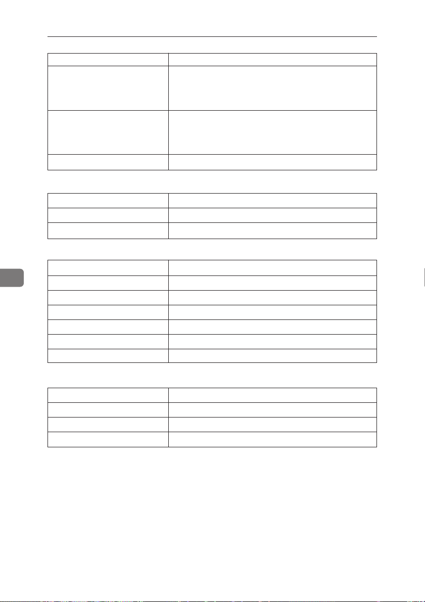
6
Troubleshooting
Item Description
Output Tray
Emulation
Program Not used for this printer
■
*1: Input Tray:Name
Messages Description
Tray1 Standard tray (Tray1)
Tray2 Optional tray (Tray2)
■
*2: Input Tray: Paper Size
Messages Description
A4R A4K
B5R B5K
LTR 81/2" × 11"K
LGR 81/2" × 14"K
EXR 71/4" × 101/2"
FRE Custom size
No. ID number of the output tray (not used for this printer)
Name Name of the output tray
Status Current status of the output tray
No. ID number of the emulation used by the printer
Name Name of the emulation used in the printer
Version Version of the emulation
■
*3: Input Tray: Status
Messages Description
Normal —
NoTray There is no paper tray
PaperEnd There is no paper in the paper tray
64
Page 84

Printer Doesn’t Print
Printer Doesn’t Print
Possible Causes
Is the power on?
Does the On Line indicator
stays on?
Does the Error indicator stay
red?
Is paper loaded in the paper
tray?
Can you print a test page (configuration page)?
Is the parallel interface cable
connecting the printer to your
computer connected securely?
Are you using the correct interface cable?
Solutions
Make sure that the power cord is securely plugged into
the power outlet and the printer. Also make sure the
printer’s power switch in the ON position.
On Line
If the On Line indicator is off, press {
=> P.5 “Operation Panel”
Check the error message on the panel display and do
the required action. => P.56 “Error & Status Messages on
the Operation Panel”
Load paper. => P.51 “Loading Paper in the Paper Tray”
If you can't print a test page, it probably indicates
printer malfunction. You should contact your sales or
service representative. => P.101 “Printing the Configura-
tion Page”
If you can print a test page but cannot get the printer to
print when you issue a print command from your computer, it probably means there is a problem with your
computer.
Also keep in mind that large, complex data might take
long time for printer process.
Connect the interface cable properly. If there are any connectors or screws, make sure they are fastened securely.
The type of parallel interface cable you should use
depends on your computer. Be sure to use the correct
one. => P.110 “Specifications”
If the cable is damaged or worn, replace it with a new
one.
} to light it up.
6
65
Page 85

Troubleshooting
6
Possible Causes
Is the Data In indicator blinking
or lit after starting the print job?
Solutions
If not, the data is not being sent to the printer.
❖ If your printer is connected to the computer
using the interface cable
Check if the printer port settings are correct. For a
parallel port connection, port LPT1 or LPT2
should be set.
• Windows 95/98
1. Click
2. Highlight the icon of the printer by clicking
3. Click
4. Check the
• Windows 3.1x
1. On the
2. Confirm that this printer is specified as the
3. Click
4. Check the
• Windows NT 4.0
1. Click
2. Highlight the icon of the printer by clicking
3. Click
4. Check
❖ Network connection
Contact your network administrator.
If the Data In indicator is blinking or lit
The printer may be resetting the print job. Take the
following steps to correct the situation.
• Increase the “Job Timeout” setting of the “IPDL-C
Menu”.
• Make sure your printer driver settings are correct.
• Change the setting of the “Transfer” of the “System Menu”.
• Make sure the “Parallel” of the “System Menu” is
correct.
[Start]
[Printers]
it. Next, on the
make sure the correct port is selected.
ers]
default printer.
correct port is selected.
[Printers]
it. Next, on the
correct port is selected.
, point to
.
[Details]
[Print to the following port]
[Control Panel]
icon.
[Connect]
[Ports]
[Start]
, point to
.
[Ports]
tab.
[The Print to port box]
[Settings]
, and then click
[File]
menu click
tab.
, double-click the
.
box to make sure the
[Settings]
, and then click
[File]
menu click
to make sure the
[Properties]
box to
[Properties]
.
[Print-
.
Note
❐ If you cannot solve the problem by taking above actions, contact your sales or
service representative.
66
Page 86
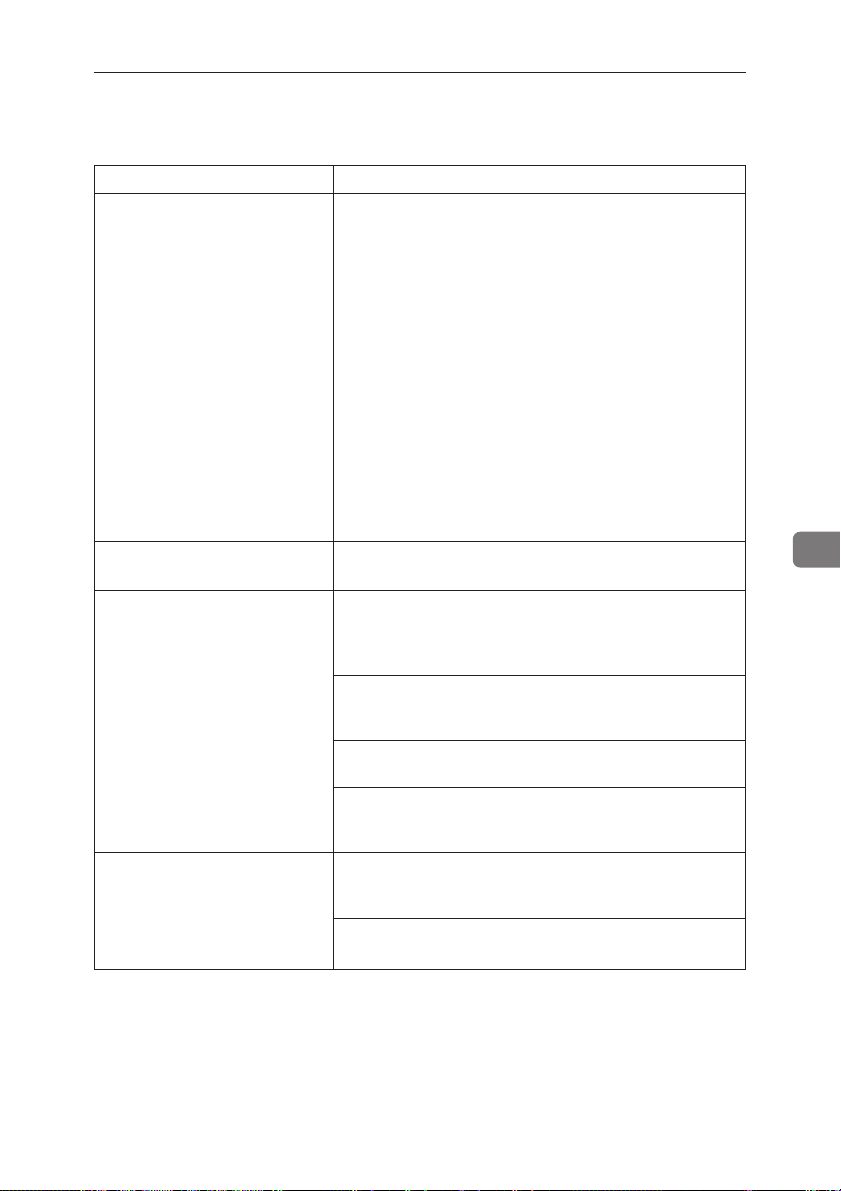
Other Printing Problems
Other Printing Problems
Status Possible Causes, Descriptions, and Solutions
The printer prints a message This message is printed when the printer does not have
indicating insufficient memory. enough memory to print a page.
The following are the actions you should take when you
encounter memory shortage problems. If these actions do
not solve the problem individually, try them in combination with each other. => P.108 “Low Memory”
1. Increase printer memory.
Install the optional memory unit to increase printer
memory capacity. => P.9 “Installing the Memory Unit”
2. Reduce resolution.
Use the printer driver to set resolution to 300dpi.
=> Help of the printer driver
=> “RICOH-SCRIPT 2 Operating Instructions”
3. Turn on “Image Memory”.
Use the printer’s “System Menu” to turn on “Image
Memory”. => P.91 “Making Printer Settings with the
Operation Panel”
Image is printed on the reverse The paper in the paper tray is upside down. Load paper
side of the paper. with the print side up.
Paper misfeeds occur frequently. Make sure you are removing misfed paper correctly.
Pull the misfed paper out of the printer and doublecheck to make sure you are removing all the paper that
was misfed. => P.71 “Removing the Misfed Paper”
Paper is not loaded correctly in the paper tray. Remove
the paper from the tray and reload it correctly. => P.51
“Loading Paper in the Paper Tray”
Check if the paper tray is set correctly. If not, set it correctly.
You might use paper not supported by this printer. Use
the appropriate type of paper. => P.49 “Paper not sup-
ported by this printer”
It takes too much time to The data is so large or complex that it takes time to
resume printing. process it. If the Data In indicator is blinking, the data
processing is being done. Just wait until it resumes.
The Energy Saver mode might be enabled. In the Energy
Saver mode, it takes time for the machine to warm up.
6
67
Page 87

6
Troubleshooting
Status Possible Causes, Descriptions, and Solutions
It takes too much time to print. Photographs and other data intensive pages take a long
It takes too much time to perform
black and white printing.
Desired tray isn’t used for the The printer driver setting is not correct. Change the
out put. setting. => “Printer Driver’s online help”
Printed side gets dirty. If the message “Change PCU” appears on the panel
Image density is too light. If turning on the
time for the printer to process, so simply wait when
printing such data.
You can also speed up printing by using the printer
driver to select
the resolution to 300dpi.
The printer takes more time to print documents that
contain a large volume of data. A blinking or lit Data In
indicator means that data is reaching the printer, so just
wait for the data to be processed and printed.
If “Warming Up” appears on the panel display, the
printer is now warming up. Wait for a while.
[Color]
is selected on the printer driver’s
Change this setting to
some applications ignore the color mode setting made
with the printer driver.
display, replace the photoconductor unit.
=> P.82 “Replacing the Photoconductor Unit”
Check the image density setting.
=> P.77 “Adjusting the Image Density”
The charge wire is dirty. Clean the charge wire.
=> P.75 “Cleaning the Charge Wire”
tab, it can cause blurring or fine lines might not be
printed. With color printing, toner saving can cause
abnormal coloring. Try printing again after turning
[Toner Saving]
further details about toner saving.
If the message “Low on: xxxx” is on the panel display,
replace the toner cartridge for the indicated color.
=> P.80 “Replacing the Toner Cartridges”
Check if the paper tray is set correctly. If not, set it correctly.
You might use paper not supported by this printer. Use
the appropriate type of paper. => P.49 “Paper not sup-
ported by this printer”
[Fast]
as the print mode, and by setting
[Setup]
[Black & White]
[Toner Saving]
off. See the printer driver’s online help for
. Note, however, that
setting on
tab.
[Quality Setting]
68
Page 88

Other Printing Problems
Status Possible Causes, Descriptions, and Solutions
Part of the printout is blurred Make the image density darker. => P.77 “Adjusting the
or light. Image Density”
Check if the toner cartridge or photoconductor unit is
installed correctly. => P.80 “Replacing the Toner Car-
tridges” and P.82 “Replacing the Photoconductor Unit”
Check if the paper tray is set correctly. If not, set it correctly.
You might use paper not supported by this printer. Use
the appropriate type of paper. => P.49 “Paper not sup-
ported by this printer”
Check if the surface where the printer is located is level,
and not angled in anyway.
White lines appear on the print If white lines appear only within a particular color,
side. remove and reinstall the corresponding toner cartridge.
Toner is not fused well when The printer is not in “Thick Paper” mode. Select
printing on thick paper.
Toner is not fused well when The printer is not in “OHP Transparency” mode.
printing on the OHP trans- Select
parencies. the printer driver's
The color of the printout does The toner based color system used by the printer is
not match the color on the different from the light based color system of the com
computer’s display. puter screen. => P.iv “Color Guide”
The printout does not match the Certain applications or image creation methods produce
image on the computer screen. images that cannot be printed exactly as they appear on
=> P.80 “Replacing the Toner Cartridges”
[Thick Paper]
[Setup]
Turning on the
driver’s
See the printer driver’s online help for details about
changing the settings on this tab.
Check the settings of the printer driver’s
tab.
See the printer driver’s online help for details about
changing the settings on this tab.
the computer screen.
Checking the
[Setup]
data before it is sent to the printer, which produces a
printout that is closest to what appears on your computer screen.
❐ This setting also causes large-volume print jobs to
in the
tab.
[Paper Type]
[OHP transparency]
[Setup]
[Toner Saving]
[Quality Setting]
[Print as bitmap]
tab causes the print data to be converted to image
Note
take longer to print because of the required conversion process.
box of the printer driver’s
in the
[Paper Type]
tab.
feature of the printer
tab can cause color irregularities.
item of the printer driver’s
box of
[Color Setting]
6
69
Page 89
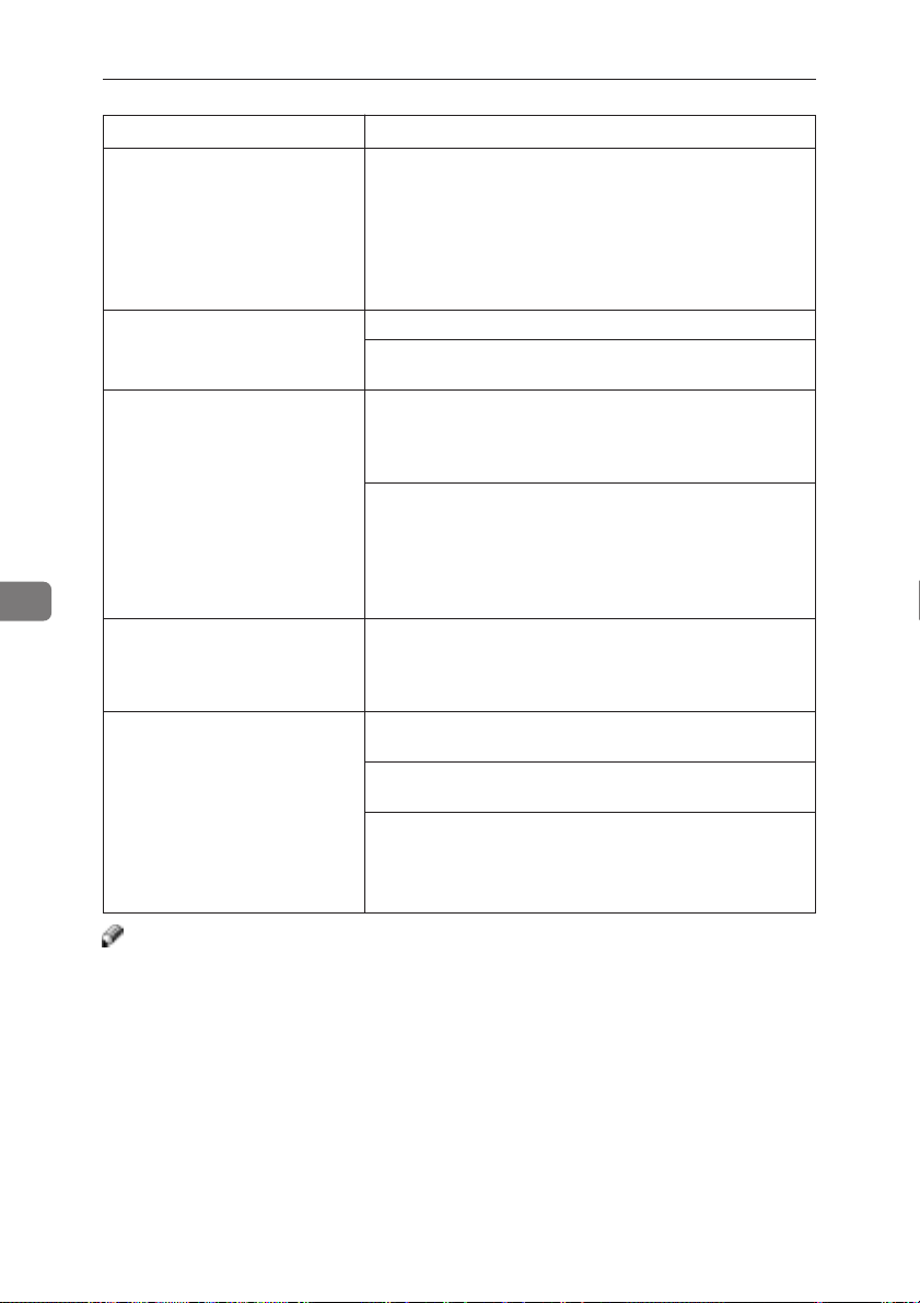
6
Troubleshooting
Status Possible Causes, Descriptions, and Solutions
Changing the color settings Do not made radical changes in the settings of the
with the printer driver causes a
drastic change in printout color. Also note that the sample shown by the printer driver is
Photograph printing looks Select
rough.
Color documents are printed The printer driver is not set up for color printing. Select
in black and white.
Fine dot patterns do not print. Select
Printer driver settings do not Install the latest version of the printer driver.
produce the desired results.
[Color Setting]
intended to show what processes are being applied, not
exactly what your printout will look like.
See the printer driver’s online help for details about
making these settings.
Printing from some applications results in a loss of
resolution.
[Color]
See the printer driver’s online help for details about
making this setting.
Some applications normally print color text as black and
white. You can obtain correct color printing with such
applications by checking the
the printer driver’s
See the printer driver’s online help for details about
making this setting.
tab.
See the printer driver's online help for details about
making this setting.
Your printer driver may not be installed correctly. Delete the printer driver, and then re-install it.
Some applications ignore the settings of the printer
driver. Check the settings of the application and printer
driver settings to make sure they are the same, and then
try printing again.
tab.
[Fine]
on the
[Print Quality]
on the printer driver’s
[Setup]
tab.
[Text]
in the
[Dithering]
list box of the
tab.
[Setup]
tab.
[Use 24 bit colors]
option in
[Color Setting]
Note
❐ If you cannot solve the problem by taking above actions, contact your sales or
service representative.
70
Page 90
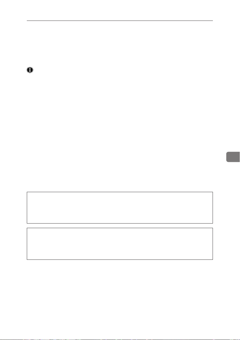
Removing Misfed Paper
Removing Misfed Paper
When a paper misfeed occurs, an error message appears on the panel display.
The procedure you should follow to remove the misfed paper depends on its
location which is indicated on the panel display.
Important
❐ T oner printed on misfed paper is not fused and can make your hands or cloth-
ing dirty. Take care to avoid contact with the toner as you remove misfed paper .
❐ Check the following points if paper continues to misfeed.
• Make sure the paper in the tray matches the size for which the tray is set up.
• Make sure the number of sheets do not exceed the maximum capacity of
the tray.
• Make sure misfed paper is still not inside the printer when you resume
printing.
• Make sure paper is properly loaded in the paper tray.
• Make sure you are using only the appropriate type of paper.
If misfeeds persist, contact your sales or service representative.
❐ Do not touch the photoconductor unit when removing misfed paper. If you
do, the photoconductor unit might be damaged.
❐ To reset the printer after a misfeed, it is necessary to open and close any of
covers.
6
R
CAUTION
•
When accessing the inside of the machine, do not touch any sections
other than those specified in this manual. If you do, it might result in
receiving a burn or injury.
R
CAUTION
•
The paper tray does not have a stopper. When pulling it out, be careful not to pull it strongly. If you do, the tray might fall and cause personal injury.
71
Page 91
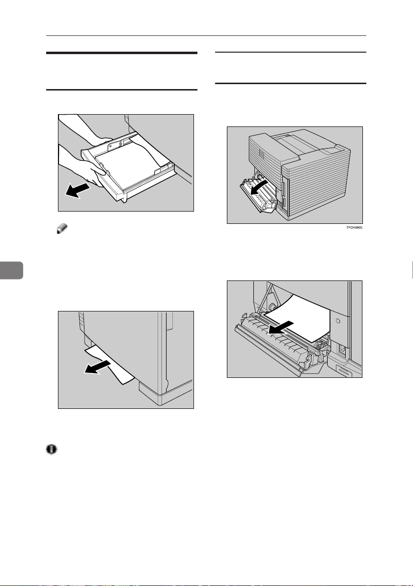
Troubleshooting
6
When the Message “Remove
Misfeed From Tray” Appears
When you cannot find the misfeed
near a tray
1 If you cannot remove the misfed pa-
A Pull out the paper tray.
TPOH480E
Note
❐ If your printer has an optional
paper feed unit installed, check
all paper trays for misfeeds.
2 Check for misfed paper . If you find
B Carefully pull the misfed paper.
Make sure that you do not leave
any misfed paper in the printer.
per in step
of the printer.
paper, carefully pull it. Make sure
not to leave any paper inside the
printer.
B, open the rear cover
C Slide the paper tray completely
into the printer.
Important
❐ Be sure to insert the paper tray com-
pletely. Otherwise, misfeeds might
occur, or the front cover might
touch the paper tray.
72
TPOH500E
3 Close the rear cover.
TPOH481E
Page 92

Removing Misfed Paper
When the Message “Open Rear
D Slide the pressure release levers to-
Cover Remove Misfeed” Appears
Important
❐ Toner printed on misfed paper is
not fused and can make your hands
or clothing dirty . Take care to avoid
contact with the toner as you remove misfed paper.
A Open the rear cover of the printer.
B If the paper has not entered the
fusing unit, carefully pull it out.
TPOH500E
C If the paper is inside the fusing
unit, open the top cover.
E Carefully pull the misfed paper
F Return the pressure release levers
wards the “OPEN” mark to release
the pressure between the rollers.
TPOH510E
from the rear cover side.
6
TPOH520E
to their original positions (“SET”
mark).
TPOH620E
G Close the top cover and rear cover,
and press the center of the top
cover until is lock securely into
place.
73
Page 93
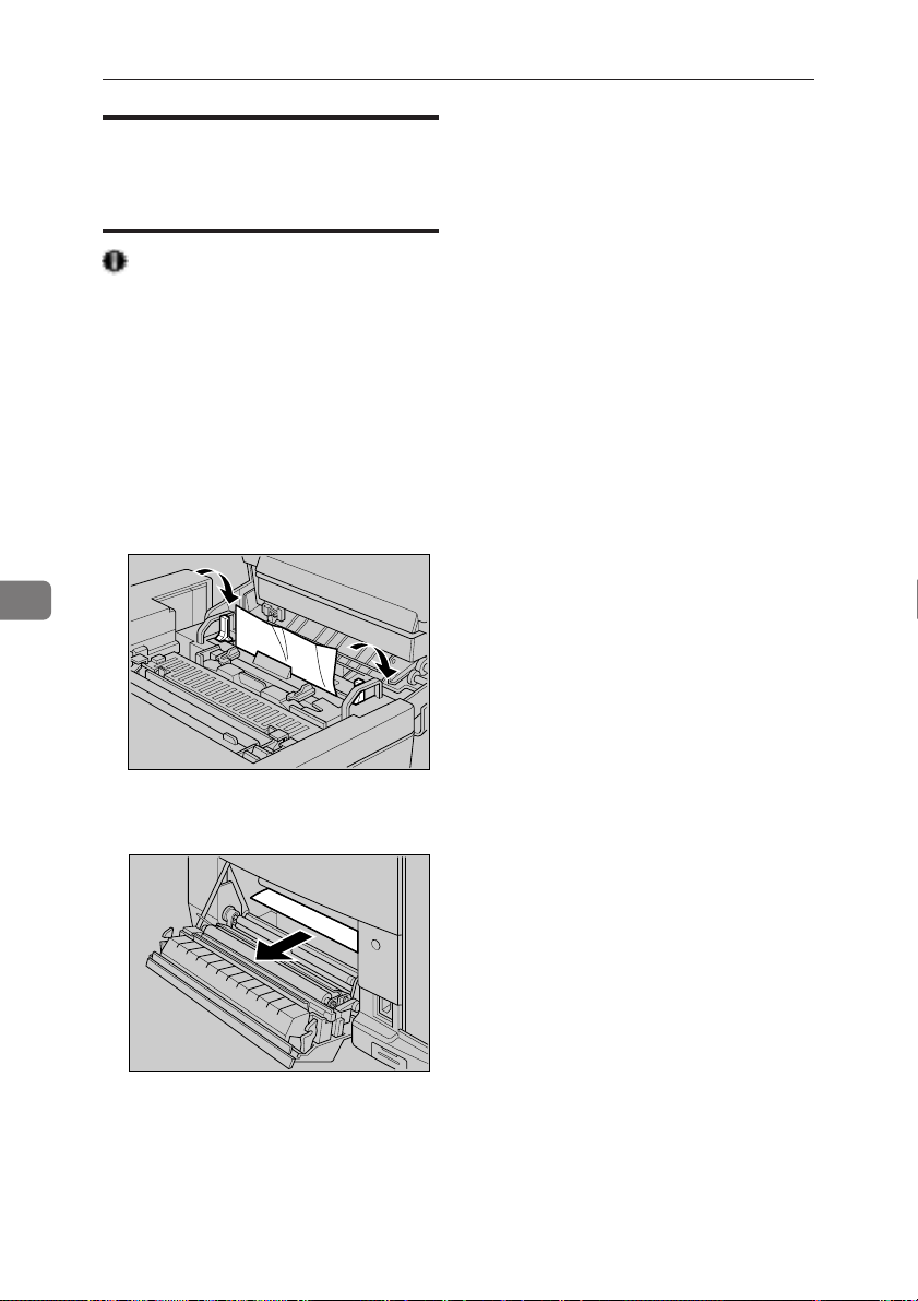
Troubleshooting
6
When the Message “Remove
E Close the top cover and rear cover,
Misfeed From Output T ray” Appears
Important
❐ Toner printed on misfed paper is
not fused and can make your hands
or clothing dirty . Take care to avoid
contact with the toner as you remove misfed paper.
A Open the printer’s rear cover.
B Open the top cover, and then slide
the pressure release levers towards
the “OPEN” mark to release the
pressure between the rollers.
and press the center of the top
cover until it locks securely into
place.
C Carefully pull the misfed paper
from the rear cover side.
D Return the pressure release levers
to their original positions (“SET”
mark).
74
TPOH510E
TPOH520E
Page 94
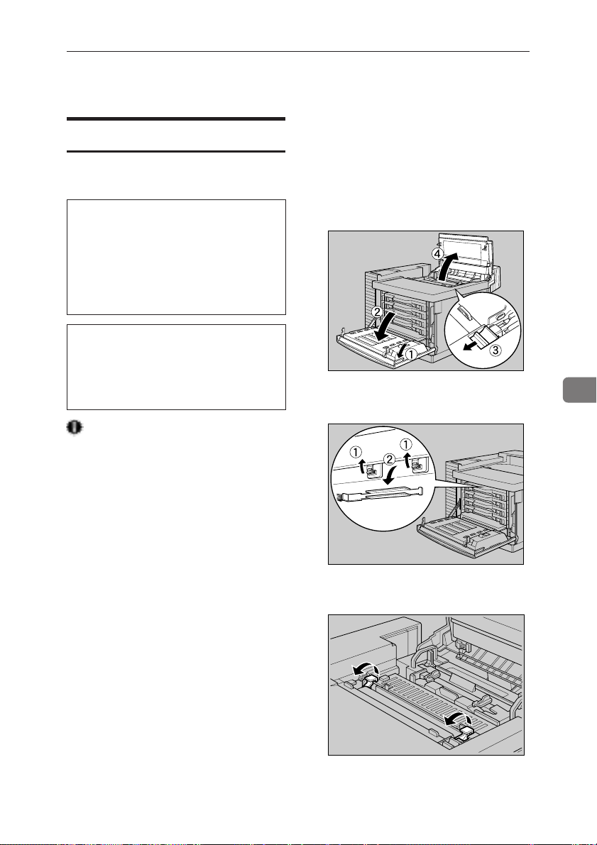
Cleaning and Adjusting the Printer
Cleaning and Adjusting the Printer
Cleaning the Charge Wire
The charge wire requires cleaning
when your printouts appear dirty.
R
CAUTION
•
When accessing the inside of
the machine, do not touch any
sections other than those specified in this manual. If you do, it
might result in receiving a burn
or an injury.
R
CAUTION
•
Do not open the front cover
when the paper tray is pulled out
halfway . If you do, it might cause
a personal injury.
Important
❐ Do not touch the surface of the
photoconductor unit. If you do, the
photoconductor unit might be damaged and the print quality might be
reduced.
❐ Do not expose the photoconductor
unit to a light source greater than
800 luxes for more than two minutes. If you do, the photoconductor
unit might be damaged and the
print quality might be reduced.
❐ Do not touch the photoconductor
unit on any surface. It you do, the
photoconductor unit might be damaged and the print quality might be
reduced.
A Press the printer’s power switch to
turn off power.
B Open the front cover by pulling
the front cover open lever and
open the top cover by pulling the
top cover open lever.
TPOH191E
C Release the brush locks (
move the wire brush (
11
1) and re-
11
22
2).
22
TPOH690E
D Stand up the green lock levers to a
vertical position.
6
TPOH560E
75
Page 95
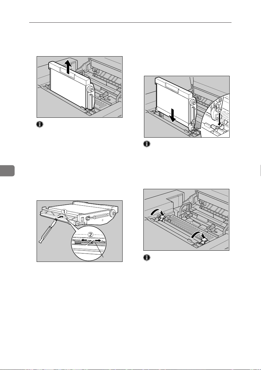
Troubleshooting
6
E Hold the inset grip of the photo-
conductor unit, pull it straight up,
and remove it from the printer.
TPOH570E
Important
❐ Exposing the photoconductor
unit to light for too long can reduce its performance. Clean the
charge wire as quickly as possible.
F Use the wire brush to clean off the
charge wire. Insert the wire brush
between the case and guide (
and then move it left and right (
11
1),
11
22
2).
22
G Insert the photoconductor unit so
that the protruding green axles on
both sides are aligned with the
tracks inside the green lock levers.
Lower it until the gears mesh securely.
TPOH230E
Important
❐ When inserting the phot-
oconductor unit, be careful not
to damage the surface of it.
H Return the green lock levers to
their original positions.
76
TPOH710E
TPOH590E
Important
❐ Do not return lock levers with
force. If you cannot lock them
easily, pull the photoconductor
unit from the printer. Then reinsert it again until the gears mesh
securely . After that, try returning
the levers to their original positions.
Page 96

Cleaning and Adjusting the Printer
I Replace the wire brush to its origi-
nal position.
TPOH700E
J Close the top cover and front cover.
Press the center of the top cover
and front cover until they lock into
place.
TPOH250E
K Press the power switch to turn on
printer power.
Adjusting the Image Density
Changing the image density setting
might cause a deterioration of color
balance. W e recommend that you nor mally leave image density at its factory default setting without changing
it.
The following procedure describes
how to change the magenta image
density. You can use the same procedure to change the image density for
the other toner colors as well.
Important
❐ Image density settings should be
made from your application or the
printer driver whenever possible.
Note
❐ After pressing a key, wait until the
display changes as described, until
you perform the next key operation.
A Press the printer’s power switch to
turn on power.
{{
B Press
{
Menu
{{
}}
}.
}}
6
TPOS040G
The following message appears on
the panel display.
<Menu> U
IPDL-C Menu T
77
Page 97

Troubleshooting
6
{U}{U}
C Use
{U} and
{U}{U}
tenance,” and then press
The following message appears on
the panel display.
{T}{T}
{T} to display “Main-
{T}{T}
{{
Enter
{
{{
<Maintenance> U
1.Toner Level T
}}
}.
}}
D After confirming that “1. Toner
{{
Enter
En-
{
{{
}}
}.
}}
{{
En-
{
{{
Level” is on the display , press
}}
ter
}.
}}
The following message appears on
the panel display.
<Toner Level> U
Cyan T
{U}{U}
E Use
{U} and
{U}{U}
genta,” and then press
The following message appears on
the panel display.
F Use
G Press
{U}{U}
{U} and
{U}{U}
toner density, and then press
}}
ter
}.
}}
The “Toner Level” menu appears.
Note
❐ To make the image density
darker, move the ◆ to the right.
To make lighter, to the left.
{{
{
{{
The normal display screen appears.
{T}{T}
{T} to display “Ma-
{T}{T}
{{
{
{{
<Magenta> UT/#
<◆––3––6––9–––>
{T}{T}
{T} to adjust the
{T}{T}
}}
On Line
}.
}}
Adjusting the Setting of “Registration” of the Optional Tray
Adjusting the registration refers to
changing the position of the printed
image on paper fed from the optional
tray so it matches that of the standard
tray. Probably you will never need to
perform this procedure.
Note
❐ After pressing a key wait until the
display changes as described until
you perform the next key operation.
1
❐ Use A4 or 8
the configuration page.
/2" x 11" paper to print
A Press the printer’s power switch to
turn on power.
{{
B Press
This displays the Printer Menu.
}}
{
Menu
}.
{{
}}
<Menu> U
IPDL-C Menu T
TPOS040G
78
{U}{U}
C Use
{U} and
{U}{U}
Print,” and then press
This displays the “List Print” menu.
{T}{T}
{T} to display “List
{T}{T}
{{
{
Enter
{{
<List Print> U
Config.Page T
}}
}.
}}
Page 98

Cleaning and Adjusting the Printer
D After confirming that “Config.
{{
Page” is on the display, press
}}
ter
}.
}}
{{
E Press
This prints the Configuration Page.
Important
❐ If printing does not start, check
the panel display for any error
messages and take the action required to correct the problem.
=> P.56 “Error & Status Messages
on the Operation Panel”
{
Enter
{{
}}
} again.
}}
{
{{
En-
F After confirming that the “Config.
Page” Menu on the display, press
{{
{
{{
The following display appears.
}}
Escape
}.
}}
<Menu> U
List Print T
G Y ou can find the crop marks on the
trailing edge of the configuration
page. Check if the left (
22
right (
2) margins on the trailing
22
edge of the configuration page as
shown in the illustration.
11
1) and
11
I Use
J Use
{U}{U}
{U} and
{U}{U}
Registration”, and then press
}}
}.
ter
}}
The following display appears.
<Tray2:W> UT/#
-<-----+---♦->+
{U}{U}
{U} and
{U}{U}
istration.
<Tray2:W> UT/#
-<-----♦----->+
The above shifts the image to the
right.
{T}{T}
{T} to display “4.
{T}{T}
{T}{T}
{T} to adjust the reg-
{T}{T}
Image
K After you are finished, press
}}
}.
ter
}}
This registers your setting and returns to the “Maintenance” menu.
{{
{
{{
{{
{
{{
En-
6
En-
H If the left and right margins are not
the same, use
play “Maintenance”, and then
{{
press
{
{{
The “Maintenance” menu appears.
{U}{U}
{U} and
{U}{U}
}}
Enter
}.
}}
<Maintenance> U
1.Toner Level T
{T}{T}
{T} to dis-
{T}{T}
L Press
{{
{
{{
The normal display screen appears.
On Line
}}
}.
}}
79
Page 99

Troubleshooting
Replacing Consumables
6
Replacing the T oner Cartridges
You should replace toner cartridges
whenever the message “Add Toner”
appears on the panel display.
The following procedure describes
how to replace the magenta toner cartridge. Y ou can use the same procedur e
to replace the toner cartridges for the
other toner colors as well.
WARNING
R
•
Do not incinerate spilled toner
or used toner. Toner dust
might ignite when exposed to
an open flame.
•
Disposal can take place at our
authorized dealer or at appropriate collection sites.
•
If you dispose of the used
toner containers yourself, dispose of them according to
your local regulations.
R
CAUTION
•
When accessing the inside of
the machine, do not touch any
sections other than those specified in this manual. If you do, it
might result in receiving a burn
or injury.
Important
❐ Exposing the photoconductor unit
to light for too long can reduce its
performance. Replace the toner cartridge as quickly as possible.
❐ Pull the toner cartridge out slowly
and carefully to prevent spilling of
toner .
Note
❐ When handling toner cartridges,
never stand them up on either end
or position them upside down.
❐ Store toner cartridges under the
conditions below.
• Temperature: 10°C to 32.5°C
(50°F to 90.5°F)
• Humidity: 20% to 80% RH (no
condensation)
❐ Before removing a toner cartridge
from the printer, spread paper or
some other material around the area
you are working to keep toner from
making floor dirty.
❐ Do not insert the toner cartridge
into the printer with force. If you
do, the printer might be damaged.
80
R
CAUTION
•
Do not open the front cover
when the paper tray is pulled out
halfway . If you do, it might cause
personal injury.
Page 100
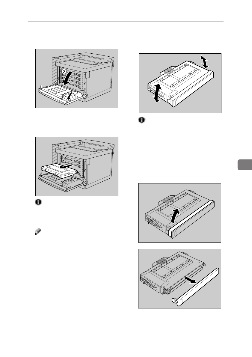
Replacing Consumables
A Open the front cover by pulling
the front cover open lever.
TPOH540E
B Carefully pull out the toner car-
tridge for the color indicated on
the panel display.
TPOT050E
Important
❐ Pull the toner cartridge out
slowly and carefully to prevent
spilling of toner.
Note
❐ Place the old toner cartridge on
paper or some other material to
avoid making the area you are
working dirty with toner.
C Hold the new toner cartridge and
shake it well, about 10 times, as
shown in the illustration.
TPOT010E
Important
❐ If toner cartridge is not shaken
enough, toner might not be
evenly distributed in the cartridge. In this case, the print
quality might be reduced.
D Remove the tape from the new
toner cartridge and remove the
protective cover.
TPOT020E
6
TPOT030E
81
 Loading...