

Page 1

POMELO-P3 (G063)
SERVICE MANUAL
[Controller]
Page 2

17 January, 2001 INSTALLATION
1. INSTALLATION
Refer to the following materials.
• For the printer: Quick Installation Guide
• For options: Operating Instructions – Setup Guide
Installation
1-1
Page 3

17 January, 2001 PERIODIC MAINTENANCE
2. PERIODIC MAINTENANCE
Refer to Section 2. Periodic Maintenance in the G063 engine service manual.
Preventive
Maintenance
2-1
Page 4
17 January, 2001 REPLACEMENT AND ADJUSTMENT
3. REPLACEMENT AND ADJUSTMENT
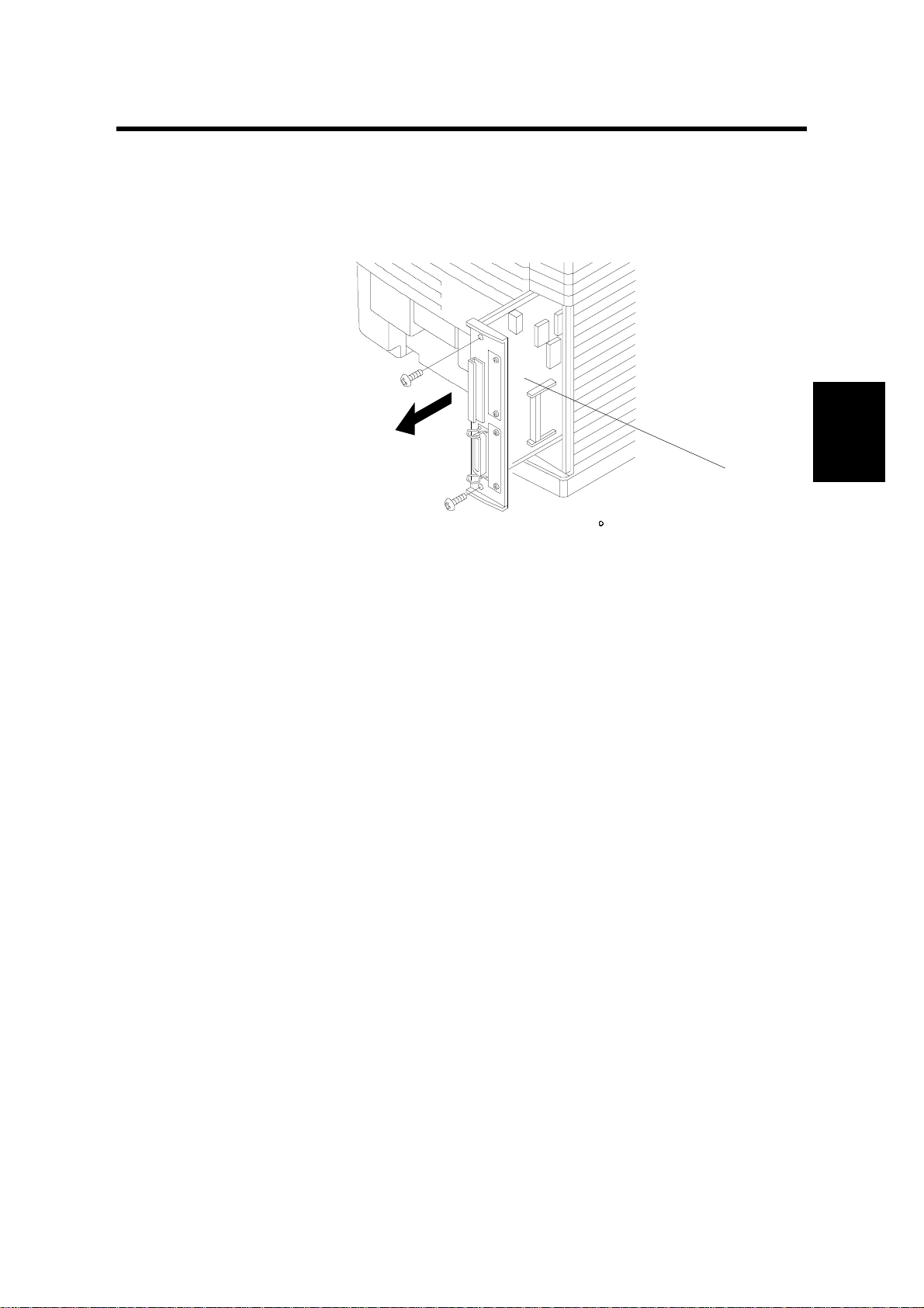
3.1 CONTROLLER BOARD REPLACEMENT
G063R092.WMF
1. Remove the printer controller board [A] (2 screws).
The following must be done after changing the board.
• Store the Printer ID (controller service mode S8)
• Store the network printer name (user mode)
• Do the gamma calibration (controller service mode S7)
3.2 REGISTRATION ADJUSTMENT
You can adjust the registration in the following three ways:
A. Controller’s user menu (Menu → Maintenance → 4. Registration);
refer to the operating instructions for more details
B. Controller’s SP mode (S5. Registration)
C. Engine SP mode (43 Margin Adjust)
[A]
Adjustment
Replacement
For tray 1, the leading edge and left side registrations can be adjusted either with
engine SP mode 43 or with controller SP mode S5 (Registration).
For tray 2, leading edge and left side registrations can be adjusted with engine SP
mode 43. The left side registration can also be adjusted with the controller user
mode, and the leading edge registration can be adjusted with controller SP mode 5
(Registration).
For how to adjust the registration, refer to ‘5. Service Tables – 5.5.1. Adjusting the
Leading Edge and Left Side Registrations’ in the engine service manual.
3-1
Page 5
REPLACEMENT AND ADJUSTMENT 17 January, 2001
3.3 IMAGE ADJUSTMENT
3.3.1 OVERVIEW
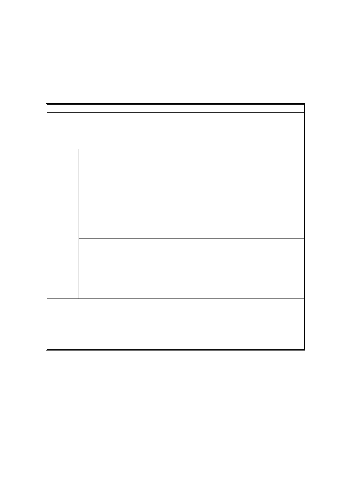
The table below lists the adjustable image parameters, with their corresponding
adjustment procedures.
Item Procedure
Brightness, Contrast,
Saturation, Color Balance
LD Power
Density
Development
Bias
Transfer Bias
Service Gamma
In the Print Quality tab of the Windows printer properties,
select the ‘Custom’ button and click ‘Setting’. A range of
adjustments is displayed. The results of the adjustments are
reflected in the image data processing by the driver and
controller.
Use either the user menu [Menu] →[Maintenance] →[Toner
Level] or engine SP mode 45-1 (LP Tune Up). You can
adjust the power for each CMYK color within a range of -1 to
+13 with the user menu and in ±4 steps in engine SP mode.
(For the actual procedures, refer to the operating instructions
and the engine service manual).
See ‘5.Service tables – 5.1.4 SP Mode Details’ in this manual
for the relationship between the settings in each of these
modes.
The settings made for this item are transferred to the engine
and stored in NVRAM on the MCTL board.
Note that the customer is able to adjust this.
Use engine SP mode 45-3 (DBV Tune Up); refer to the
engine service manual. You can adjust the bias for each
CMYK color in ±4 steps.
The settings made for this item are transferred to the engine
and stored in NVRAM on the MCTL board.
Use either controller SP mode S4 (Transfer Bias) or engine
SP mode 45-2 (THV Tune Up). You can adjust in ±4 steps for
plain paper, OHPs, and labels.
Use controller SP mode S7 (Gamma Calib.). You can adjust
each color for both text and photograph modes. The results
of the adjustment are reflected in the gamma correction done
by the controller (see ‘3. Replacement and Adjustment –
3.3.2 Service Gamma Adjustment’ and 6. Detailed
Descriptions – 6.1.2 Controller Gamma’ in this manual for
more information on how the controller does this).
3-2
Page 6
17 January, 2001 REPLACEMENT AND ADJUSTMENT
3.3.2 SERVICE GAMMA ADJUSTMENT
NOTE: For problems related to color quality and gradation, clean the engine and
replace supplies and other parts at first. Use this mode only when the
customer insists on further fine adjustments (e.g., matching colors between
machines).
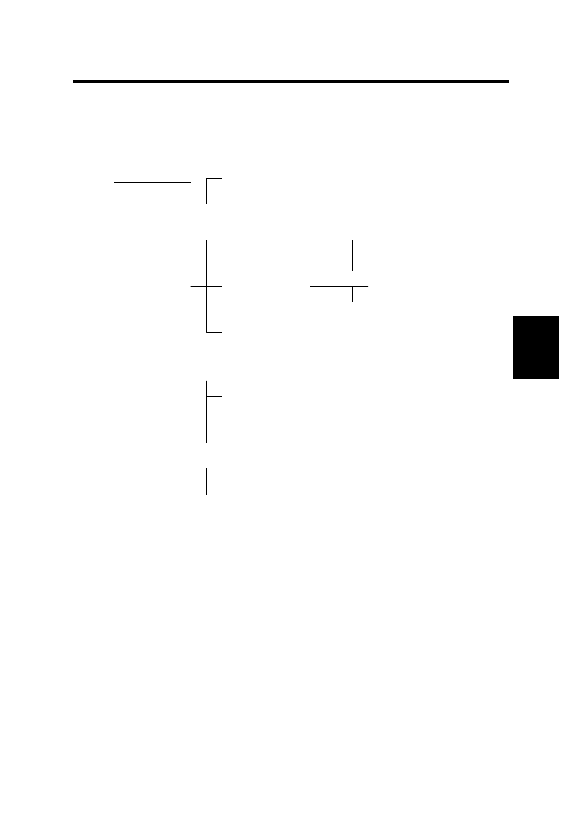
Adjustment Menu (Controller SP, S7. Gamma Calibration)
The menu items under Gamma Calibration in controller SP mode are organized as
shown below. See “5. Service tables – 5.1.3 SP Mode Menu Hierarch,” in this
manual for instructions on how to access the “S7. Gamma Calib. Color Correction”
menu.
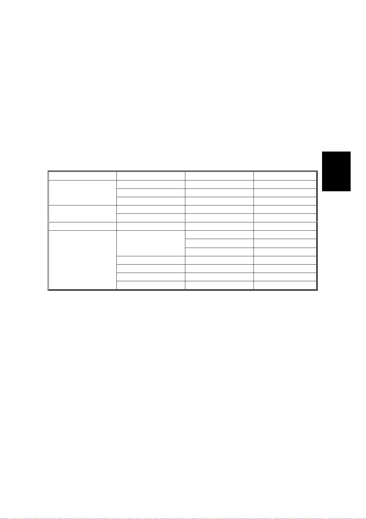
Layer 3 Layer 4 Layer 5 Layer 6
Load Setting
Print Setting
Gamma Setting
Default
Setting-Old
Setting-Current
1 bit/PhotoMode Setting
1 bit/Text
Black
Cyan Same as above Same as above
Magenta Same as above Same as above
Yellow Same as above Same as above
Save Settings
K/01th.[xxx] K/01th.=xxx/255
↓↓
K/15th.[xxx] K/15th.=xxx/255
(continued on the next page)
Adjustment
Replacement
3-3
Page 7
REPLACEMENT AND ADJUSTMENT 17 January, 2001
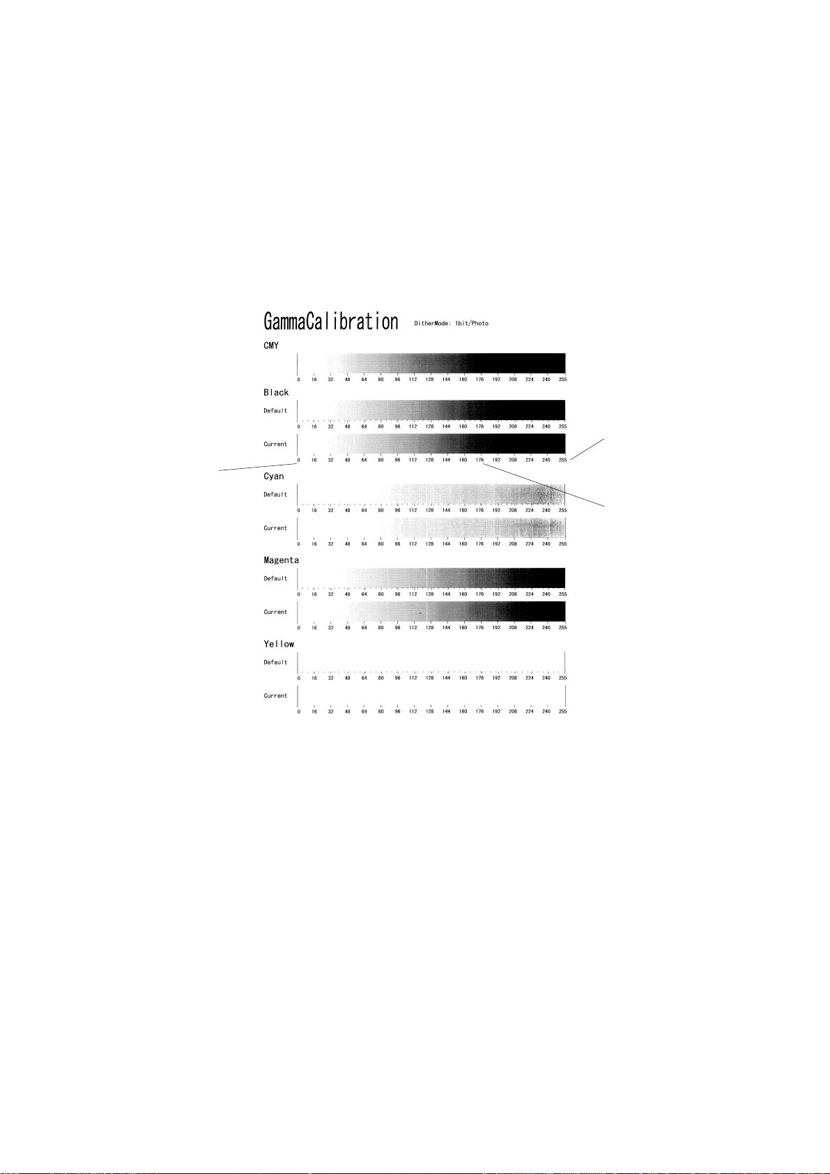
Adjustment Overview
To carry out this adjustment, select the print mode to adjust (text or photograph),
then print out a color adjustment sheet. Make the gradation scales on the printout
smooth from the lowest to the highest density. Adjust the CMY gradation scale at
the top of the chart by balancing the density of the C, M, and Y gradation scales –
the CMY gray scale should change smoothly from minimum to maximum, and
there should be no coloration.
The color adjustment sheet is as follows.
[C]
[B]
[A]
G063R503.BMP
For each color, you can adjust 15 points (example [A]) between 0 (lowest density)
[B] and 255 (highest density) [C]. For each point, you can adjust the density within
0 and 255.
The gradation scales marked ‘Default’ are printed according to the default gamma
settings in the flash ROM in the controller. The gamma adjustment changes the
densities at the adjustable points in the gradation scale. The gradation scale
marked “Current” sho ws th e current settings.
During the adjustment procedure, compare the “Current” gradation scale with the
‘Default’. Select the density for each of the 15 adjustable points, excluding points 0
and 255, from the ‘Default’ gradation scale.
3-4
Page 8

17 January, 2001 REPLACEMENT AND ADJUSTMENT
The NVRAM holds three controller gamma settings, those saved this time (SettingCurrent), those saved in the preceding adjustment (Setting-Old), and the factory
settings (Default).
Adjustment Procedure
1. Select “Load Setting” and load the settings that will serve as the base for the
adjustment.
2. Select “Mode Setting”, and select the print mode that you are going to adjust
(text or photograph).
3. To review the image quality for these settings, choose “Print Setting” to print
out a color adjustment sheet (Gamma Calibration at the top of the page).
4. Select “Gamma Setting”. Then select a color (K, C, Y, or M).
5. Adjust the color density at each of the 15 points.
NOTE: To decide what density value to input, do the following.
1. Look at the color adjustment sheet.
2. For the color you are adjusting, look at the gradation scale entitled
‘Default’.
3. Go along the scale until you reach the density that you wish to
input.
4. Read off the value on the scale and store it in the machine.
5. Do the same for all 15 points.
6. When the density setting is complete for all colors, print out a color adjustment
sheet again and make sure that the gradation scale for each printed color is
smooth and that the CMY gradation scale is gray. Repeat the adjustment if
there is an anomaly (normally, repeat this procedure 3 to 5 times).
7. If the adjustment results prove satisfactory, do the following:
1) Execute “Save Settings”.
2) Reset the controller (press the [Reset] key when the machine is off line”) to
use the new settings.
NOTE: The new settings will not be saved in the controller NVRAM unless you
reset the controller.
Adjustment
Replacement
3-5
Page 9

REPLACEMENT AND ADJUSTMENT 17 January, 2001
3.3.3 SOFTWARE UPGRADE PROCEDURE
Required Tool
- IC card Adapter (G0319350)
- IC card containing new firmware
The controller, RICOH-SCRIPT2 and network interface boards have a flash ROM
for storing control software. This allows version upgrades using an IC card.
NOTE: Before starting an upgrade procedure, make sure that the software in the
IC card is newer than the software in the controller, RICOH-SCRIPT2, or
network interface board.
To check, print out a configuration page (user mode).
Follow the procedure shown below to upgrade the software:
1. Turn off the machine, and then unplug all cables from the parallel interface
board(s) and network interface board, if connected.
2. Install IC card into IC card adapter.
3. Remove the controller board. Then install the IC card adapter in either optional
bus I/F slot 1 or slot 2.
4. Put the controller board back in the machine.
5. Turn on the machine. The machine automatically copies the firmware from the
IC card to the appropriate flash ROM (controller, RICOH-SCRIPT2, or network
interface board).
CAUTION: 1) Do not turn off the machine while the software is being updated.
Otherwise, the controller, NIB, or RICOH-SCRIPT2 module ma y be
damaged.
2) Do not turn off the machine until at least 30 seconds after the
message “OK!!OK!!” or “DOWNLOAD OK.” appears.
3-6
Page 10

17 January, 2001 REPLACEMENT AND ADJUSTMENT
For the controller or RICOH-SCRIPT2:
The LCD display on the operation panel changes as shown below as the
rewrite procedure proceeds. (‘MELT’ is displayed during the software upgrade
for RICOH-SCRIPT2 since it involves a decompression process.)
(MELT ->) ERASE -> WRITE -> VERIFY -> OK!!OK!!
The appearance of the message “OK!!OK!!” indicates that the controller has
received the data from the IC card. However, note that it takes about 30
seconds to rewrite the data in the controller or RICOH-SCRIPT2 after this
message is displayed.
The message NG!!NG!!” is displayed if an error occurs during the rewrite
process. If this condition occurs, reinstall the IC card and turn the power off and
on again.
For the network interface board:
The appearance of the message “DOWNLOAD OK.” indicates that the
controller has received the data from the IC card. However, note that it takes
about 30 seconds to rewrite the data in the network interface board after this
message is displayed.
Adjustment
Replacement
DOWNLOAD -> ############ -> DOWNLOAD OK.
The message “DOWNLOAD NG.” is displayed if an error occurs during the
rewrite process. If this condition occurs, reinstall the IC card and turn the power
off and on again.
4. When the rewrite ends, turn off the main unit, reset all DIP switches to OFF, and
remove the IC card.
5. Replace the IC card cover. Turn the power on again and print the user mode
configuration page.
6. Check the new software version and make sure that it matches the version on
the IC card.
3-7
Page 11
17 January, 2001 TROUBLESHOOTING
4. TROUBLESHOOTING
4.1 TYPES OF PROBLEMS
The problems can be classified as follows.
Printer-side Print Settings
•
Operation
Hardware
Printer-side Initial Settings
•
Host-side Application Settings
•
•
Faulty Engine
Faulty Controller
•
Hardware Limitations
•
•
Main Unit
•
Option
•
Consumables
Main Unit
•
•
Option
Software
Operating
conditions
•
Bug in Controller ROM
•
Bug in Emulation Module Software
Controller Limitations
•
•
Bug in Host-side Application
•
Host-side Application Limitations
•
Environment (power, temperature and humidity,
dust, noise, vibration)
•
Consumables
G063T500.WMF
Trouble-
shooting
4-1
Page 12

TROUBLESHOOTING 17 January, 2001
4.2 TROUBLESHOOTING PROCEDURE
4.2.1 HARDWARE TESTS
1. Power-up self-diagnostics
Turn on the power and check that an error code is not displayed.
After the system starts, check for error messages on the configuration page
that is automatically printed.
2. Detailed diagnostic test
See “4.Service Tables - Detailed Self-diagnostics Mode” in this manual for the
procedure.
3. Checking the configuration page output.
Print out from the user menu: [Menu] → [List Print] → [Config. Page]. If error
messages are included, check the relevant part of the machine and replace any
defective components.
4. Connectivity test
Make a test print from a computer.
• Check that the correct cable is used (and connected properly).
• Check the cable continuity.
• Check the cable length (is it too long?).
• Do not connect the printer to the computer through a printer selector switch
– connect the printer to the computer directly.
• If the optional parallel interface is installed, connect the computer to the
parallel interface board that is being tested.
4.2.2 OPERATION-RELATED TESTS
Check the print conditions and initial settings.
Check the printer settings against the application settings. Check whether the
current settings match the settings on the configuration page that the customer
keeps.
NOTE: Ask the customer to print a configuration page at some time when the
controller is working normally, and keep it for reference.
4-2
Page 13

17 January, 2001 TROUBLESHOOTING
4.2.3 SOFTWARE-RELATED TESTS
Obtain information about the following:
• PC model
• OS type and version
• Configuration page
• Application software used, and the version
• Data file being printed when the problem occurred (if obtainable)
• RICOH-SCRIPT2 data file when the problem occurred
• Sample printouts when the error occurred and when the printer is normal
• Detailed operating procedure
• Controller system and emulation module version
• Firmware versions (engine, controller, NIB)
Trouble-
shooting
4-3
Page 14

TROUBLESHOOTING 17 January, 2001
4.3 ERROR MESSAGES
4.3.1 OVERVIEW
The error messages that this unit can issue are classified as follows:
1. Controller Self -diagnostics Errors
Errors detected while the unit performs power-up self-diagnostics/detailed selfdiagnostics on the controller hardware.
2. Controller User Errors
Errors caused because the controller software cannot process the job because
of, for example, insufficient memory.
3. Internal Errors
Errors caused because the controller’s control function fails to function
normally.
4. Engine User Errors (Cautionary)
Errors that do not require user intervention to continue printing (the printer can
still communicate with the PC over the interface). However, for the best printing
quality, the user should correct the problem as soon as possible.
5. Engine User Errors
Severe errors that cause the unit to stop printing, requiring the user to fix the
problem before printing again.
6. Engine Service Codes (SCs)
Severe errors that cause the unit to stop printing, requiring a technician to fix
the problem before printing again.
Only one error message can be displayed at once. There is an order of priority for
displaying the errors. This is as follows, starting with the highest priority: Internal
Errors, Controller Se lf-diagnostics Errors, En gine Service Codes (SCs), Engine
User Errors, Engine User Errors (Cautionary), Controller User Errors.
4-4
Page 15

17 January, 2001 TROUBLESHOOTING
4.3.2 CONTROLLER SELF-DIAGNOSTICS ERRORS
When a contro ller self-diagnostics error occurs, the error code is displayed on the
first line of the operation panel LCD.
The second line contains an 8-digit code that gives details of the error for
designers to debug the error. For a memory error, the second line of the LCD
indicates the address in which the error occurred. For errors other than memory
errors, the second line always reads “FFFFFFFF”.
Code Description Location
00XX Exception processing error Controller
0101 Flash ROM sum check error Controller
0201 Standard memory read/write error Controller
0301/0401 Optional memory read/writ e error
Non-fatal error (printed as B0 in the error
log.)
060X CPU exception self-diagnostics error Controller
0D0X ASIC timer error Controller
0F0X ASIC engine interface error MCTL/Controller
11XX ASIC Centronics interface error
Non-fatal error (printed as B1 in the error
log.)
1401 NVRAM error Controller
1601 Font ROM error Controller
170X IC card error
1703 represents a non-fatal error (printe d as
B4 in the error log.)
1B0X Optional Interface 1 Error Controller
1C0X Optional Interface 2 Error Controller
1D0X Optional par allel interface board
Non-fatal error (printed as B6 in the error
log.)
250X Optional emulation module error
Non-fatal error (printed as B5 in the error
log.)
400X FPU error Controller
450X ASIC compression/decompression error Controller
Optional memory
Controller
IC card/Controller
Optional paralle l int e rface
board
Emulation module/Contr oller
Trouble-
shooting
4-5
Page 16

TROUBLESHOOTING 17 January, 2001
4.3.3 CONTROLLER USER ERRORS
Display Description Location/action
85: Error
86: Error
91: Error
94: Error
A3: Error
A6: Error Overflow during compression Install additional memory.
A7: Error
A8: Error
AB: Error Print overrun Install additional memory.
B0: Error
B1: Error Standard parallel interface err or Interface cable/controller
B3: Error
B4: Error IC card slot error Controller/IC card
B5: Error
B6: Error
B7: Error
Graphics environment i nit ialization
error
Invalid control code paramet er Incorrect printer driver or
Font/image environ me nt initialization
error
Download data error Incorrect ‘total memory size’
Receive buffer overflow Increase the I/O buffer size
Error during drawing processing
Error during library drawing Switch the machine off/on. If
Optional memory error Reinstall/replace optional
Invalid initial setup setting Reset the printer settings using
Optional emulation mo dule error Reset/replace emulat ion
Optional parallel int e rface board
error
Optional network interface board
error
Optional memory/Controller
incorrect cable installed
Install additional memory.
setting in the driver
using the system menu (user
mode)
Use a smaller font size or a
less complex font, or replace
the controller
that does not work, replace the
controller.
memory.
‘Menu reset’ in the
Maintenance menu (user
mode).
module.
Reset/replace optional parallel
interface board
Reinstall/replace net w ork
interface board
4-6
Page 17

17 January, 2001 TROUBLESHOOTING
4.3.4 INTERNAL ERRORS
When an internal error occurs, the message “Err Power Off/On” is displayed on the
first line of the operation panel LCD. The internal error code is on the second line in
the format “Error XXYY-ZZZZZZZZ” (“XX” denotes a classification code; “YY”
denotes a process number, and “ZZZZZZZZ” indicates the program address where
the error occurred).
The classification code portions (XX) and their descriptions are shown below. The
“YY” and “ZZZZZZZZ” portions are for designer use only (for debugging).
Code (XX) Description
00 Error in the TLB user area.
01 CPU TLB update exception
02 CPU mis match exception (load or fetch)
03 CPU mis match exception (store)
04 CPU addres s error exception (load or fetch)
05
06 CPU bus error exc ept i on (load or fetch)
07 CPU bus error exc ept i on (st ore)
08 CPU sy stem call exception
09 CPU break point exception
10 CPU reserv ed instruction exception
11 CPU coproc essor disabled exception
12 CPU operati on overflow exception
13 CPU trap exception
14 Coherency (instruction) error
15 CPU float ing-point operation exception
16 CPU timer interrupt
17 EAGLE level 4 interrupt (ART or Tim)
18 EAGLE level 3 interrupt (CP)
19 EAGLE level 2 interrupt (XINT1 or XINT0)
20 EAGLE level 1 interrupt (CBE, DBE, Dtc0, Verr, F in, Vdtc, Fout)
21 EAGLE level 0 interrupt (Debug)
22 Software interrupt
23 Software interrupt
24 Other CPU exceptions
25 Memory allocation error
26 Overflow error
27 Frame allocation error
28 Card eject error
29 Printer engine error
30 Option board error
31 Session-to-net w ork interface board communications error
CPU address error exception (store)
Trouble-
shooting
4-7
Page 18

TROUBLESHOOTING 17 January, 2001
4.3.5 ENGINE USER ERRORS (CAUTIONARY)
The unit can continue printing even when one of the messages listed below is
encountered.
Display Description
Low on: XXX Toner near end
XXX denotes the color name
(CMYK or their combination).
Chg. Cleaner Fusing cleaner replacement
time arrived
Fusing Oil Fusing oil near end 30
Change PCU Photoconductor unit
replacement time arrived
Change 120K 120k maintenan ce requested Information only
Change Fuser
Fusing unit replacement time
arrived.
Number of sheets until warning
500 at a 5% image ratio (300
sheets for Black).
1,000 at a 5% image ratio
Information only
Information only
state
4-8
Page 19

17 January, 2001 TROUBLESHOOTING
4.3.6 ENGINE USER ERRORS
The unit can no longer continue printing when one of the following messages is
displayed:
Display Description
Add Toner XXX Toner end (XXX: Cyan, magenta, yellow, or black)
Waste Toner is
Full
Fusing Oil Fusing oil end
Paper Size Error Paper size error
Change Fuser
Cleaner
Paper Type Error Media mismatch
Load YYY tray
XXX
Reset Paper Tray
Correctly
Close Top Cover Paper exit cover open
Close Front Cover Front cover open
Reset XXX Toner
Correctly
Close Rear Cover Rear cover open
Reset Fusing Unit
Correctly
Reset PCU
Correctly
Reset Cleaning
Roller Correc tly
Remove Misfeed
from Tray XXX
Waste toner bottle full
Fusing cleaner needs replacement.
Paper end (XXX denotes a tray name and YYY a paper size.)
No tray
No toner cartridge (XXX denotes a color name.)
No fusing unit
No photoconductor unit
No fusing cleaner
Paper jammed
Trouble-
shooting
4-9
Page 20

TROUBLESHOOTING 17 January, 2001
4.3.7 ENGINE SERVICE CODES
When an engine service call (SC) erro r occurs, an error me ssage is displayed on
the operation panel LCD in the format “Call Service SC: XX” where XX denotes an
error code. The engine SC error codes and their descriptions are shown below.
For the troubleshooting procedures, refer to the engine service manual.
Display Description
SC: EC
SC: 22
SC: 23
SC: 24
SC: 25
SC: 31
SC: 33
SC: 34
SC: 35
SC: 41
SC: 42
SC: 43
SC: 44
SC: 45
SC: 51
SC: 52
SC: 53
SC: 54
SC: 55
SC: 61
SC: 62
SC: 63
SC: 64
SC: 65
SC: 66
SC: 71
SC: 72
SC: 73
SC: 74
SC: 75
SC: 76
SC: 81
SC: 83
SC: 84
SC: 85
SC: 86
Engine communication error
Development motor error
Main motor error
Polygon mirror motor error
Charge corona voltage (CHV) error
Fusing thermistor error
Fusing temperature error (warming-up time error)
Fusing temperature error (temperature too low)
Fusing temperature error (temperature too high)
Beam sensor error
Laser power error
NVRAM error (MCTL)
Engine controller MCTL hardware error
Process timing clock error (main motor clock error)
Quenching lamp error
Toner end sensor error
Control fan error
Ozone fan error
Fusing fan error
Yellow development clutch error
Magenta development clutch error
Cyan development clutch error
Black development clutch error
HPSI signal error (retraction error for the black and yellow toner cartridges)
HPSI signal error (retraction error for the cyan and magenta toner cartridges)
Transfer drum rotational error
Transfer roller contact solenoid error
Cleaner contact solenoid error
Cleaner clutch error
Fusing unit clutch error
Belt sensor error
Duplex unit controller error
Duplex unit lower solenoid error
Duplex unit motor error
Duplex unit upper solenoid error
Duplex unit fan motor error
4-10
Page 21

17 January, 2001 SERVICE TABLES
5. SERVICE TABLES
5.1 SP MODES
5.1.1 OVERVIEW
The printer has two types of SP modes:
1. Engine SP modes
2. Controller SP modes
This section deals with controller SP modes.
5.1.2 ENGINE SP MODE
Refer to the service manual for the engine for how enter engine SP mode and use
the engine SP modes.
5.1.3 CONTROLLER SP MODE
Entering and Exiting Controller SP Mode
[A]
[B]
Power
Error
Media
G063S000
On Line
EscapeMenu
Enter
#
Data in
Reset
[A]
[B]
#
G063S001
To enter controller SP mode: Turn on the printer while holding down the [On
Line] [A] and [Reset] [B] keys on the operator panel. Hold the keys down until all
of the LEDs and the LCD turn on. Then after the printer completes its cycling, press
the [Menu] key.
Tables
Service
To exit controller SP mode: Turn the main switch off and, after a brief period,
back on.
NOTE: When accessing controller SP mode, “SP” is displayed in the upper right
corner of the display. Do not forget to exit SP mode after servicing. If
inadequately left in controller SP mode, users could change settings or
clear all settings by accident.
5-1
Page 22

SERVICE TABLES 17 January, 2001
SP Mode Menu Hierarchy
The table below shows the controller SP mode menu hierarchy. The individual
layers in the table below can be accessed in the controller SP mode by pressing
the [Enter] key. When in SP mode, S1 to Sa are added to the Maintenance menu.
Layer 1 Layer 2 Layer 3 Layer 4
Maintenance
1.Toner Level Cyan
Magenta
Yellow
Black
2.Reinstall Fuser Cleaner
Photoconductor Unit
3.Menu Reset
4. Registration L:Tray 2
5. Menu Protect Off
On
S1.Maint. Page
S2.Color Chart
S3.Maint. Clear Fusing Unit
120k
S4.Transfer Bias Plain paper
Thick paper
OHP paper
S5.Registration W:Tray 1/2
L:Tray 1
S6.Clear All Memo
S7.Gamma Calib. Load Setting Default
Mode Setting 1 bit/Photo
Print Setting
Gamma Setting Black
S8.Printer ID
S9 Toner Limiter Text
Photograph
Sa Meter Click Off
Print/Jam
Develop. Count
Print Count
It can also be accessed if
the [Enter], [Escape],
and [Menu] key s ar e
pressed in sequence
when the printer is on line.
Setting-Old
Setting-Current
1 bit/Text
Cyan
Magenta
Yellow
Save Settings
5-2
Page 23

17 January, 2001 SERVICE TABLES
5.1.4 SP MODE DETAILS
S1. Maintenance Page
The table below explains the contents of the engine maintenance list printout. The
controller obtains the data from the engine (MCTL).
Item Description
MCTL
firmware
Registration
setting
Toner density
setting
Total counter Indicates the total number of printouts and the total number of toner images
Maintenance
counter
The MCTL board firmware version number.
For tray 1, the leading edge and left side registrations can be adjusted either
with engine SP mode 43 (Margin Adjust) or with controller SP mode 5
(Registration).
For tray 2, the leading edge and left side registrations can be adjusted with
engine SP mode 43 (Margin Adjust). The left side registration can also be
adjusted with a controller user mode (Registration Adjustment), and the leading
edge registration can be adjusted with controller SP mode 5 (Registration).
For how to use this adjustment, see ‘5.Service Tables – 5.5.1 Adjusting the
Leading Edge and Left Side Registrations’ in the engine service manual.
The registration values can be adjusted in 0.5 mm increments in either the
controller or the engine SP mode. Whichever mode is used, the settings are
stored in the NVRAM on the MCTL.
Indicates the following:
LD power setting for each toner color (CMYK)
Transfer roller voltages for plain paper, thick paper, and OHPs
Development bias for each toner cartridge (CMYK)
These values can all be adjusted with engine SP mode. LD power can also be
changed with the user menu (Density Setup) and the transfer bias values can
be changed in controller SP mode (S4. Transfer Bias).
See the explanation after this table for more about this part of the printout.
made in each of the CMYK toners. The counter is incremented when the paper
exit sensor detects the completion of paper exit (regardless of paper size, type,
and mono/color mode).
Indicates the following for the fusing cleaning roller, fusing unit, and 120k
maintenance parts:
Next life limit counter (expected number of prints remaining)
Current value of the total counter
Lifetime of the part (fixed), divided by 100 to get a % value on the report
Amount of expected life time remaining
Indicates the following for the belt cartridge:
Next life limit counter (expected number of images remaining)
Sum of the current values of the CMYK image counters
Lifetime of the part (fixed), divided by 100
Amount of expected life time remaining
The formula used is as follows:
(Next Life Limit - Total Counter)/Life Period = Life remaining (%)
The values of the next life limit counters, except for 120k maintenance, vary
according to the image ratio or the job sizes during the life of the part. For
details, see ‘5.Service Tables – 5.5.3 Setting the Next Life Limit Value’ in the
engine service manual.
Tables
Service
Meter Click The selected Meter Click mode is shown.
SC Logging The latest 6 SC codes are shown.
The codes in square brackets are internal engine error codes.
5-3
Page 24

SERVICE TABLES 17 January, 2001
Item Description
Jam Logging The latest 6 jam codes are shown.
00: No Error (Initial stored data)
01: Entrance
02: Internal
03: Around the transfer drum
04: Exit
05: Duplex (Upper)
06: Duplex (Lower)
Toner density setting
The displayed value of the laser power when it is set in engine SP mode differs
from when it is set from the user menu. Both values are included in the printout, as
shown below. The following is an example for cyan (C).
C (Laser Power: SP [Usr]) +1 [08]
Value displayed in engine
SP mode
Value displayed in user
mode
The table below compares the density settings that are set from the user menu
(“Toner level”) with those set in engine SP mode.
As seen from the table, finer adjustments are possible with user mode.
User Mode
Display Value
-1 -4
0-3
1-3
2-2
3-2
4-1
5-1
60
70
8* 1*
91
10 2
11 2
12 3
13 4
Engine SP
Mode Display
Value
*: Default setting
5-4
Page 25

17 January, 2001 SERVICE TABLES
S2. Color Chart
This prints a color test chart, so that the image quality can be tested for all colors at
various densities. This chart can be printed on all paper sizes supported by the
machine (the layout of the print pattern varies from paper size to paper size).
S3. Maintenance Clear
This mode resets the maintenance counters for the fusing unit replacement or 120k
maintenance parts (these counters are in the NVRAM on the MCTL board). Use it
after doing the PM required for these units. See ‘4.Service Tables – Setting the
Next Life Limit Value’ in the engine service manual for information about how to
use this SP mode.
S4. Transfer Bias
This mode adjusts the transfer roller voltages used for the three paper types (plain
paper, thick paper and OHP transparency) supported by this unit. For each paper
type, you can set the value in 4 increments. The settings are stored in the NVRAM
on the MCTL board.
Default value: 0
S5. Registration
This mode adjusts the leading edge registration for trays 1 and 2 and the left side
registration for tray 1. You can set each value in ±7 increments (1 step = 0.5 mm).
The values are stored in the NVRAM on the MCTL board. See ‘4.Service Tables –
Adjusting the Leading Edge and Left Side Registrations’ in the engine service
manual for information about how to use this SP mode.
NOTE: Engine service mode 43 (Margin Adjust) can be used to adjust all of the
registrations, whereas controller SP mode S5 can only adjust a few of
them.
S6. Clear All Memory
Executing this function resets the following user settings, stored in the NVRAM on
the controller, to their initial values:
• Emulation/system initial setup items
• Printer ID
• Printer name on the network
• Gamma calibration
The “Menu Reset” clear function in the user menu only resets the emulation/system
initial setup items to their initial values.
Tables
Service
5-5
Page 26

SERVICE TABLES 17 January, 2001
S7. Gamma Calibration
This mode adjusts the gamma tables used in text and photograph modes.
NOTE: For problems with color quality and gradation, clean the engine and
replace consumables and other parts at first. Use this mode only when the
customer insists on further fine adjustments (e.g., matching colors between
machines)
See “3. Replacement and Adjustment – 3.3.2 Service Gamma Adjustment” in this
manual for the adjustment procedure.
S8. Printer ID
The printer ID allows the RICOH-SCRIPT2 emulation module to identify the printer
main unit. It is programmed in the NVRAM on the controller at the factory.
When replacing the controller, it is necessary to use this SP mode to re-input the
printer ID since the printer ID for the old controller is required.
Follow the procedure given below to input the printer ID:
1. Select the first digit using the [!!!!] and [""""] keys.
2. Input the number by pressing the [Enter] key (you can use the [Escape] key to
cancel the setting if you input an incorrect number).
3. Repeat these steps until the last digit is entered. Pressing the [Enter] key on
the last digit returns you to the “S8. Printer ID” menu.
4. Print a configuration page and verify that the correct printer ID is defined.
5. Turn the power off and on again to exit SP mode.
S9. Toner Limiter
The maximum toner values can be adjusted from 100 to 400% for both Text and
Photo Modes. The default value for both is 250%.
If this value is set high, the printed image appears more true to the original data.
However, since a greater amount of toner is used, it is easy to scatter the toner
around lines and text areas. If the value is set low, the color balance of low-density
areas varies, however toner does not scatter as easily.
5-6
Page 27

17 January, 2001 SERVICE TABLES
Sa Meter Click
In this mode, the counting method can be selected depending on the type of
service contract.
When meter click mode is activa ted, the machine is affected as follows:
1. A new user mode, “Show Counter” displays the counter values.
2. The printer will stop printing when toner has run out. In addition, “Toner Empty”
disappears from the Maintenance menu.
3. The configuration sheet includes the value for the counting method selected in
Meter Click mode, not the total counter value. Both counter values are included
in the engine maintenance sheet.
4. After selecting meter click mode, the counter value for the selected counting
method is automatically set to 0. However, it cannot be reset to 0 after the
machine begins counting.
5. All developments/prints are counted at paper exit.
6. Counting method:
1) By developments
B/W Image
Color Counter +1 +2 +3 +3
Black Counter +1 +1
1C image 2C image 3C image Full color
2) By prints
B/W Image
Color Counter +1 +1 +1 +1
Black Counter +1
1C image 2C image 3C image Full color
7. The following are not counted:
1) The final page when printing an odd number of pages in duplex mode.
2) The engine maintenance sheet, color chart and gamma calibration sheets in
controller SP mode.
3) All sheets printed out in engine SP mode.
4) The Low-Memory Error Sheet.
5) A list of settings (B/W) if a non-fatal error is detected during Self-Diagnostics.
Tables
Service
5-7
Page 28

SERVICE TABLES 17 January, 2001
5.2 DETAILED SELF-DIAGNOSTICS MODE
Overview
In this mode, the controller tests components that are not tested during the powerup self-diagnostics. These are the memory, standard parallel interface, and options
(optional interfaces, Memory slot and DIMM slot), if the devices are installed.
The following special tools are required to execute this mode:
Parallel Interface Loopback Connector
Part No. Type of Interface Remarks
G0219350 For the standard parallel
interface board
G0109350 For the optional parallel
interface board
NOTE: A decal with the part number is attached to each connector, to avoid
confusing the two types.
If not used, the controller continues t he test
to the end, but flags a non-fatal error.
If an interface board is inst alled but the
loopback connector is not, the cont roller
continues the test to the end, but fl ags a
non-fatal error.
Operating Procedure
[A]
Power
Error
On Line
EscapeMenu
[A]
Data in
Reset
[B]
[B]
#
Media
G063S000.WMF
Enter
#
G063S001.WMF
To enter the detailed self-diagnostics mode, make sure that the devices that you
wish to test are installed. Then do the following.
1. Switch off the power.
2. Connect the loopback connector to the parallel port. If the optional additional
parallel interface has been installed, connect the loopback connector for this
port also.
3. Turn on the power while simultaneously pressing and holding down the [On
Line] [A] and [Enter] [B] keys on the operation panel. Hold the keys down until
all of the LEDs and the LCD turn on.
5-8
Page 29

17 January, 2001 SERVICE TABLES
Operation Panel Behaviour during Detailed Self-diagnostics
Immediately after power is turned on
The controller turns on all LEDs and the LCD.
During detailed self-diagnostics
When the controller starts the self-diagnostics, it turns off all LEDs except the
Power LED and causes the Power LED to blink. It displays the message “Service
diag” on the LCD.
When the tests terminate normally
When an error does not occur during the self-diagnostic test, the controller causes
the blinking Power LED to stay on and turns off all the other LEDs and the LCD.
The controller starts the system immediately afterward and prints out a list of
settings in color mode.
When an error is detected
Errors are divided broadly into non-fatal errors and fatal errors. The controller takes
different actions and gives different status information for different types of errors.
• When a non-fatal error (user error) is detected
The controller turns the blinking Power LED on, turns off all of the other LEDs
and the LCD, and restores the standby display. Since non-fatal errors do not
adversely influence any print operation, the controller starts the system
immediately after it takes these actions.
The system turns on the Error LED and prints out a list of settings with error
descriptions in monochrome mode (see 4. Troubleshooting – 4.3.3 Controller
User Errors in this manual for the error codes).
After printing a list of settings, the system returns to the normal state and sets up
all devices except the failed device.
• When a fatal error is detected
Since there is no guarantee that the system can generate a list of settings after
detecting a fatal error, the system turns off the Power LED and turns on the Error
LED. At the same time, it displays an error message on the LCD until the power
turns off.
The first line of the LCD contains a 4-digit code that identifies the error and the
second line contains an 8-digit code that gives details of the error for designers
to debug the error (see 4. Troubleshooting – 4.3.2 Controller Self-diagnostics
Errors in this manual for a description of the error codes).
Tables
Service
5-9
Page 30

SERVICE TABLES 17 January, 2001
Detailed Self-diagnostics Flow
Chart
Turn On Power
Code ROM sum check
Tests the timer functions of
the EAGLE 2
Read/write test
Operation test
Tests the engine interface functions of the
EAGLE 2 and KOTO; makes a loopback
test on the standard Centronics interface
Read/write test
Code ROM sum check
IC card sum check (if
card is installed)
Test Code ROM
Test Timer
Test Memory
Test CPU
Test ASIC
Test NV-RAM
Test Font ROM
IC Card installed?
Yes
Test IC Card
Fatal Error Detected
Fatal Error Detected
Fatal Error Detected
Fatal Error Detected
Fatal Error Detected
Display error on panel
No
DIMM (emulation module)
sum check
Optional parallel interface
board loopback test (if board
is installed)
Yes
Test DIMM
Optional Parallel
I/F installed?
Yes
Test Optional Parallel I/F
Start System
Generate list of
settings
No
G063M503.WMF
5-10
Page 31

17 January, 2001 SERVICE TABLES
Test Results Printout when No Fatal Errors Occur
If a non-fatal error occurred, the report is printed in black and white. The “Error
Log” section at the bottom of the printout explains the non-fatal errors that
occurred.
If no error occurred, the report is printed in color. The “Error Log” section contains
“None”.
The right side of the sample printout contains gradation patterns in the following
colors, from the top, C, M, Y, K, R, G, B, and CMY.
5.3 BRAND SETTING
Operating Procedure
Power
Error
On Line
Data in
Reset
[C]
[B]
EscapeMenu
[A]
#
Media
G063S000
Enter
#
G063S001
1. Press the [!!!!][A], [""""] [B], and [Menu] [C] keys sequentially.
2. Select “S1. Brand” in the Maintenance menu.
Layer 1 Layer 2 Layer 3 Layer 4
Maintenance S1.Brand RICOH JPN
RICOH EXP(Default)
SAVIN
Gestetner
NRG
[C]
[B]
[A]
Tables
Service
3. Press the [Reset] key to reboot the machine.
5-11
Page 32

17 January, 2001 FUNCTIONAL OVERVIEW
6. DETAILED DESCRIPTIONS
6.1 FUNCTIONAL OVERVIEW
6.1.1 PRINT DATA PROCESSING
The diagram below shows the print data processing path. The boxes in the
diagram represent function blocks and the text next to the arrows indicates the
data type. The diagram is followed by a brief description of color processing by the
printer driver.
IPDL-C Driver
BG/UCR
CMYK 8bit
Gamma
Correction
CMYK 8bit
Maximum
Toner Control
Dithering
CMYK 1/2bit
Amount
CMS
Controller
CMYK 8bit
Gamma
Correction
Table
Maximum
Amount Value
(for service)
1/2bit
Text/Photo
Dither
PS Driver
RGB 8bit CMYK 8bitRGB 8bit
RPS2 Module
(including CMS)
BG/UCR
Manual Gamma
Correction
Detailed
Descriptions
MCU
Printer Engine
Operation Panel
G063D500.WMF
NOTE: 1-bit color for 600 x 600 dpi printing and 2-bit color for 1200 x 600 dpi
mode printing
6-1
Page 33

FUNCTIONAL OVERVIEW 17 January, 2001
CMS (Color Management System)
CMS adjusts the RGB values of the colors in the application data in preparation for
RGB to CMYK conversion, which is done in the controller.
A file known as a ‘profile’ (filename extension ‘prf’) is automatically installed in the
\windows\system\ folder during printer driver installation. This file contains
instructions for CMS on how to convert the colors in the print data produced by the
application.
CMS is used whenever the color correction setting in the printer driver is set to any
value other than “Off”.
Color Adjustment by the Driver
The driver adjusts the following parameters in accordance with the driver settings
made by the user: Brightness, Contrast, Saturation, and Color Balance.
The driver does not perform RGB to CMYK color conversion.
Color Conversion, Gamma Conversion, and Dithering by the Controller
The controller performs gamma conversion (see Gamma Correction), RGB-toCMYK conversion, and dithering.
6.1.2 GAMMA CORRECTION
Gamma correction in this model has two components: controller gamma (nonadjustable) and service gamma (adjustable).
Controller gamma
This gamma is programmed into the flash ROM in the controller. If there has been
no service gamma adjustment in the machine so far since installation, the controller
gamma is the only gamma that is used (i.e., service gamma = 0).
Service gamma
This gamma is stored in the NVRAM in the controller. It can be adjusted using
controller SP mode (S7. Gamma Calibration). See “3. Replacement and
Adjustment – 3.3.2 Service Gamma Adjustment” in this manual for the adjustment
procedure.
The controller combines the service gamma (the default setting is zero) with the
controller gamma when doing gamma correction.
6-2
Page 34

17 January, 2001 FUNCTIONAL DESCRIPTION
6.2 FUNCTIONAL DESCRIPTION
6.2.1 CONTROLLER LAYOUT
VIDEO I/F
DIP SW
ASIC
KOTO
CPU
RM5261
Optional Memory I/F
Optional BUS I/F 1 Optional BUS I/F 2
ASIC
EAGLE 2
Flash
Font ROM
NVRAM
Detailed
Descriptions
IEEE 1284 I/F
6-3
G063D501.WMF
Page 35

FUNCTIONAL DESCRIPTION 17 January, 2001
6.2.2 FUNCTIONS OF COMPONENTS
Device Function
CPU RM5261-250
ASIC EAGLE 2 This ASIC controls the following:
• Memory mapping
• Reset
• DRAM
• Data received from the parallel
• Video DMA
• PvDMA
• Interrupt
• Serial communication with engine
• IEEE1284 interface
• Timer
•
I/O Port
ASIC KOTO Video da t a interface
FLASH ROM Stores program (2 MB) The flash ROM is programmable via an IC
card.
NVRAM
FONT ROM Stores internal printer fonts.
Program ROM RICOH-SCRIPT2 Emulat ion Modul e
DIP SW
Stores the initial settings and printer parameters.
(8 KB EEPROM)
(One 64-Mbit mask ROM)
The emulation module is progra mmable by IC card.
1234
5678
OFF
G063C004.WMF
SW No. Setting Content
1OFF
2ON
3-8 OFF
Set this switch ON when downloading
MCTL firmware.
Do not touch these switches in the field.
Video I/F Interface the controller with the pr int er engine.
IEEE1284 I/F Provides an interface that connects to a local host (IEEE1284
compliant).
Option Bus I/F
• Two slots; each can hold either an optional network interface or
a parallel interface board. You cannot install two boards of the
same type.
• IC card adapter for downloading the Controller and MCTM
firmware.
Option RAM I/F A slot for accommodating the memory.
6-4
Page 36

17 January, 2001 POWER-UP SELF-DIAGNOSTICS
6.3 POWER-UP SELF-DIAGNOSTICS
6.3.1 OPERATION PANEL DISPLAY DURING POWER-UP SELFDIAGNOSTICS
The controller starts power-up self-diagnostic tests when the printer power is
turned on. It shows the test status on the panel as the self-diagnostics proceed.
Immediately after turning the power on
The controller turns on all LEDs and the LCD.
During power-up self-diagnostics
When the controller starts the self-diagnostics, it turns off all LEDs except the
Power LED, which it causes to blink. It displays the message “Warming UP” on the
first line of the LCD.
If the test terminates normally
If an error is not detected during the self-diagnostic test, the controller turns the
blinking Power LED on and turns off all the other LEDs and the LCD. The
controller starts the system immediately afterwards.
If an error is detected
Errors are divided broadly into fatal and non-fatal (user) errors. The controller takes
different actions and gives different status information for different types of errors.
See section 4 (Troubleshooting) for tables o f the di ffer ent ty pes of err ors .
Detailed
Descriptions
6-5
Page 37

POWER-UP SELF-DIAGNOSTICS 17 January, 2001
Non-fatal error (user error) detected
The controller causes the blinking Power LED to stay on, turns off all of the other
LEDs and the LCD, and restores the standby display state. Since non-fatal errors
do not adversely affect any print operation, the controller starts the system
immediately after it takes these actions.
The system turns on the Error LED and prints out a list of settings with error
descriptions, in monochrome mode (see section 4 Troubleshooting – 4.3.3.
Controller User Errors in this manual for the error codes).
After printing the above list of settings, the system returns to the normal state and
enables all devices except the failed device.
Fatal error detected
Since there is no guarantee that the system can generate a list of settings when
the error detected is fatal, the system turns off the Power LED and turns on the
Error LED. At the same time, it displays and keeps an error message on the LCD
until the power is turned off.
The first line of the LCD contains a 4-digit code that identifies the error. (see
section 4 Troubleshooting – 4.3.2 Controller Self-diagnostics Errors in this manual
for a description of the error codes).
6-6
Page 38

17 January, 2001 POWER-UP SELF-DIAGNOSTICS FLOW CHART
6.4 POWER-UP SELF-DIAGNOSTICS FLOW CHART
Turn on power
Fatal Error
Code ROM sum check
Tests the timer functions
of the EAGLE 2
Operation check
Tests the engine interface functions
of the EAGLE 2 and KOTO
Font ROM sum check
Test Code ROM
Test Timer
Test CPU
Test ASIC
Test Font ROM
Detected
Fatal Error
Detected
Fatal Error
Detected
Fatal Error
Detected
Fatal Error
Detected
IC card sum check, if IC
card is installed
IC card installed?
YES
Test IC card
YES
Test DIMM
Non-fatal Error
(user error)?
YES
Start System
Generate List of
Settings
NO
NO
Display Error on
Panel
Detailed
Descriptions
Start System
6-7
G063M057.WMF
 Loading...