

Page 1
Technical
Reissued: 30-Jun-99
Bulletin
PAGE: 1/1
Model:
Pomelo
Date:
30-Apr-99
No.:
RG033001a
RTB Correction
The items in bold italics have been corrected or added.
Subject:
From:
Classification:
Detailed Self -diagnostics Error
Technical Service Dept., GTS Division
Troubleshooting
Mechanical
Paper path
Other ( )
Part information
Electrical
Transmit/receive
Prepared by:
Action required
Service manual revision
Retrofit information
H. Someya
Symptom:
When the detailed self-diagnostics is executed if an optional memory board (16MB or 32
MB) is not installed in the main unit, the following error message appears on the LCD and
the machine stops the diagnostics.
In power-up self-diagnostics mode, this problem does not occur.
00FF
9FC0B4A4
Cause:
Software bug
Possible Unit:
G033-17: P0690100001 – 348
G033-27: P0690100349 – 648
Solution in the field:
Before executing the detailed self-diagnostics, install an optional memory board
temporarily.
Solution on the product line:
The firmware for the controller has been changed from the following version.
Controller firmware version: 1.0.1
Controller part number (suffix): G0335701B
Page 2

T
echnical
B
ulletin
PAGE: 1/1
Model:
Subject:
From:
Classification:
Please correct the following paragraph on page 4-7 of the service manual.
Incorrect:
This procedure displays, for each of the maintenance parts, the number of printouts (or
toner images in the case of the belt counter) remaining before replacement is required.
These counters can also be seen by printing the engine maintenance page with controller
SP mode S1.
Correct:
This procedure displays, for each of the maintenance parts, the counter value at which
each of them is required (this is toner images in the case of the belt counter). These
counters can also be seen by printing the engine maintenance page with controller SP
mode S1.
Pomelo
Service Manual Correction
Technical Service Dept., GTS Division
Troubleshooting
Mechanical
Paper path
Other ( )
Part information
Electrical
Transmit/receive
Date:
30-Apr-99
Prepared by:
No.:
RG033002
H. Someya
Action required
Service manual revision
Retrofit information
Page 3
RICOH Technical
Bulletin
PAGE: 1/1
Model:
Subject:
From:
Classification:
Symptom:
Uneven or faint image
·
SC41 appears.
·
Cause:
Dust entering from the holes in the base adheres to the 2nd mirror over time.
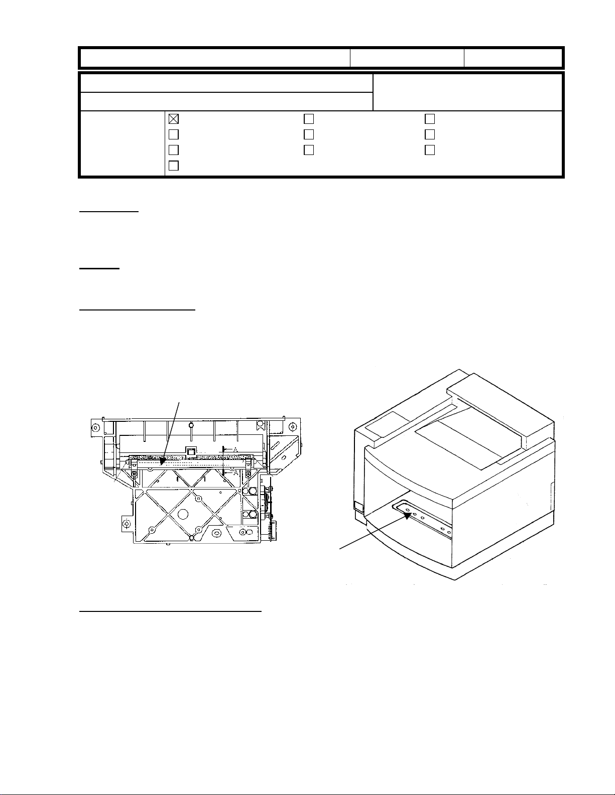
Solution in the field:
1. Remove the optical unit and clean the 2nd mirror with an optical cloth.
2. Use tape to block the 6 holes in the base.
3. Reassemble the machine.
Pomelo
Uneven or faint image / SC41
Technical Service Dept., GTS Division
Troubleshooting
Mechanical
Paper path
Other ( )
Part information
Electrical
Transmit/receive
Date:
15-Aug-99
Prepared by:
Action required
Service manual revision
Retrofit information
No.:
H. Someya
RG033003
2nd mirror
Back of optical unit
Solution on the production line:
Polyester tape has been attached to block the 6 holes in the base (effective as of February
production runs).
The following polyester tape has been registered as a service part.
Part Number: V126239
·
Description: Polyester Tape – 20 pcs
·
Note: The above part contains 20 pieces of tape (as one set).
6 holes
Page 4

RICOH Technical Bulletin PAGE: 1/2
Model: Pomelo Date: 15-Aug-99 No.: RG033004
Subject: SC76 (belt slips to the side) Prepared by: H. Someya
From: Technical Service Dept., GTS Division
Classification:
Troubleshooting
Mechanical
Paper path
Other ( )
If SC76 occurs, take the following action:
1. Install the machine on a stable and level surface.
2. Place the three wedges that have been packed together with the machine under each
of the three feet.
3. If SC76 still occurs, attach the spacer to the machine according to the following
procedure.
Procedure for attaching the spacer:
1. Remove the belt cartridge.
2. Measure the gap L between side plate and OPC belt as shown in diagram 1.
3. Do one of the following actions depending the length of gap L:
Gap L (mm) Required action
0 – 3 Attach one spacer to the bearing on side A as shown in diagrams 2
& 3.
3 – 7 No action necessary
7 - 10 Attach one spacer on the bearing on side B as shown in diagrams
2 & 3.
Note: Clean the area of the bearing where the spacer will be attached with a cloth.
4. Install the belt cartridge and the turn on the machine.
5. Measure gap L after the machine has finished warming up.
6. If gap L is 3 mm to 7 mm, this procedure is complete. If gap L is less than 3 mm or
more than 7 mm, repeat this procedure from step 3 (attach one more spacer).
Note: Do not attach more than 2 spacers.
Part information
Electrical
Transmit/receive
Action required
Service manual revision
Retrofit information
Diagram 1
gap L
Page 5

RICOH Technical Bulletin PAGE: 2/2
Model: Pomelo Date: 15-Aug-99 No.: RG033004
Side A
Side B
Diagram 2
side A
Shape of the spacer:
4 mm
8 mm
side B
Places where spacers are attached
Diagram 3
Thickness: 0.2 mm
Page 6

RICOH Technical
Bulletin
PAGE: 1/2
Model:
Subject:
From:
Classification:
Symptom:
Pomelo
Early problem with Ricoh NIBs when using IE 5.x
Technical Services Dept., GTS Division
When you browse the Pomelo and FresaWIN printers with Microsoft Internet
Explorer 5.x (IE 5.x), IE 5.x requires installing a Japanese font even if the HT ML
does not have a Japanese font.
i.e., if browsing http://
message appears:
Troubleshooting
Mechanical
Paper path
Other ( )
Printer IP Address
Date:
Part information
Electrical
Transmit/receive
/en/cgi-bin/sts_index.cgi, the following
29-Feb-00
Prepared by:
Action required
Service manual revision
Retrofit information
No.:
H. Someya
RG033005
Maybe the message is different because of a minor variation in the IE version or
Windows OS. The above message appears when using IE 5.00.2920.0000 with
Windows 2000. In this case, IE requires a Japanese font every time.
IE 5.00.2314.10003 with Windows NT 4.0 is shown below. In this case, IE requires
a Japanese font once after browsing the Ricoh NIB (network interface board).
Note:
The NIB works properly by canceling messages stating that a Japanese font
is required.
Page 7

RICOH Technical
Bulletin
PAGE: 2/2
Model:
Cause:
Problem NIB version
Problem printers
Pomelo
The HTML in the older version Ricoh NIB has the following line:
<META HTTP-EQUIV="content-type" CONTENT="text/html;
CHARSET=x-sjis">
This line means that HTML declares this file’s code is Japanese. Therefore IE 5.x
requires installing a Japanese font even if all HTMLs do not have a Japanese font.
The problem Ricoh NIB versions are 3.8.7 or earlier. The latest Ricoh NIB does not
include the problem line. Th e lat est one has the foll owing line:
<META HTTP-EQUIV="content-type" CONTENT="text/html">
This problem only happens with Pomelo and FresaWIN. However, the latest
Pomelo and FresaWIN do not have the problem. It depends on the time when the
NIB was produced.
Date:
29-Feb-00
No.:
RG033005
Other printers and MFPs, such as Stinger-C, Russian-C/P, and Win-A, do not have
this problem because these Ricoh NIB versions are 3.8.8 or later.
Countermeasure 1
First check the Ricoh NIB version by printing the configuration page (Menu button
<Menu> List Print à <List Print> Config. Page). The configuration page shows
à
the Network Version line as follows:
Network
Version ELAND98 3.7.5 (0003)- 3.60f9
This line shows NIB version is 3.7.5.
If the NIB version is 3.8.7 or earlier, please get the latest Ricoh NIB firmware and
install the new one in the NIB.
Countermeasure 2
Install a Japanese font in Windows. There are a few ways to install Japanese fonts.
1) If IE 5.x is pre-installed in Windows 2000, the Windows 2000 CD-ROM has
Japanese fonts. The customer should insert the CD-ROM and click the OK
button.
2) Use Windows update from the Start up Menu in Windows and install the
Japanese font.
Page 8

!"#$% T
echnical Bulletin
PAGE: 1/1
Model:
Subject:
From:
Pomelo
Insufficient Transfer / Jitter
Technical Services Dept., GTS Division
Classification:
Troubleshooting
Mechanical
Paper path
Other ( )
Part information
Electrical
Transmit/receive
Date:
29-Nov-00
Prepared by:
No.:
RG033006
H. Someya
Action required
Service manual revision
Retrofit information
The MCTL board firmware has been modified in order to minimize the following. In
addition, the development drive unit was modified to minimize item #3.
1. Insufficient transfer in a band near at leading edge equivalent to one turn of the
development roller.
2. Dark lines on the printout at intervals of one development roller rotation.
3. Jitter at about 50 mm from the leading edge
Solutions:
1. For both #1 and 2 above:
The firmware has been changed so that if a large amount of prints are made using
only one DTM, the machine will rotate the development rollers in the unused DTMs at
the end of the job.
2. For #3 above:
The development drive unit has been modified so that the DTM drive speed is reduced
to about half speed. Also, the MCTL board firmware was modified in order to
synchronize the color switching timing with this new drive speed.
Notes concerning firmware solutions:
Old development
drive unit
P/N: V126162
New development
drive unit
P/N: V126246
Old MCTL firmware
P/N:V126187 (version 1-4)
(No solution) Solution for symptoms 1
(No interchangeability) Solution for symptoms 1 ,
New MCTL firmware
P/N:V126535 (version 1-5)
and 2
2 and 3
Note: The old development gear unit will continue to be available as a service part.
Please refer to MB# MG033005 for the cut-in serial numbers.
Page 9

!"#$% T
echnical Bulletin
PAGE: 1/1
Model:
Subject:
From:
Pomelo
SC76
Technical Services Dept., GTS Division
Classification:
Troubleshooting
Mechanical
Paper path
Other ( )
Part information
Electrical
Transmit/receive
Date:
29-Nov-00
Prepared by:
No.:
RG033007
H. Someya
Action required
Service manual revision
Retrofit information
This RTB explains the OPC modification related to SC76 (belt tracking) as well as some
notes for servicing in the field.
Modification:
The OPC has been modified from the serial number mentioned below, but not as a direct
countermeasure for SC76. The modification simply made the occurrence conditions of
SC76 more strict, allowing the machine to continue operating on some surfaces that are
not perfectly level. So although there is still a limit, the machine's tolerance of inclined
surfaces has increased.
Action in the field:
SC76 normally does not occur if the machine is installed using three wedges on a sturdy,
level surface. Therefore, if SC76 occurs, take the action described in RTB #RG033004
first. The spacer for this countermeasure has been registered as a service part
(#G0449000).
NOTE: This service part is actually one set of 200 spacers.
Production Units:
The OPCs have been modified from the following cut-in serial numbers:
G033-17: P0690800001
G033-27: P0690900001
OPCs: Lot # xxxxxD or later (the lot # is written on the side plate of the OPC cartridge.)
Page 10

echnical Bulletin
T
PAGE: 1/1
Model:
Subject:
From:
Pomelo
Controller Firmware Modification History
Technical Services Dept., GTS Division
Classification:
Troubleshooting
Mechanical
Paper path
Other ( )
Part information
Electrical
Transmit/receive
Date:
07-Feb-01
Prepared by:
Firmware history for Pomelo.
Suffix Version Check Sum Production
G0335901
A 1.0.0 1st release
B 1.0.1 February Prod. ‘99
C 1.0.2 December prod. ‘99
D 1.1.1 EDDA June Prod. ‘00
E 1.1.2 1C7A February Prod. ‘01
Change Applied / Symptom Corrected
When the detailed self-diagnostics are executed if an optional
memory board (16MB or 32 MB) is not installed in the main unit,
error message "00FF" appears on the LCD and the machine
stops the diagnostics.
Wording corrections for the LCD and configuration page
The following two functions have been added to the IPDL-C
menu in SP mode. This is the same as the Fresa Win+.
• Minimum Line Width Adjustment
• Toner Usage Display
The default setting of IPDL-C timeout has been changed from
300 s to 999 s.
It is possible to specify the paper feed trays for both the 1st and
2nd/onward pages in the MS-Word Page Setup menu.
Network Settings will not be cleared with UP Mode Menu Reset.
If there is no paper of the required size in Auto Paper Select
mode and the "If the required paper size is not available, printing
will not start" checkbox has not been checked in the printer
driver, the printer will feed from the tray specified as the default in
the System Menu, instead of from the Current Tray (previous
method).
No.:
RG033008
H. Someya
Action required
Service manual revision
Retrofit information
B
C
D
D
E
E
E
Page 11

echnical Bulletin
T
PAGE: 1/1
Model:
Subject:
From:
Pomelo
ROM History (PomeloWIN RPS2)
Technical Services Dept., GTS Division
Classification:
Troubleshooting
Mechanical
Paper path
Other ( )
Part information
Electrical
Transmit/receive
Date:
Prepared by:
Firmware history for the PomeloWIN RPS2.
Suffix Version Check Sum Production
G5035907
B 2.61 85E5 April Prod. 2000
C 3.10 9643 November Prod. 2000
D 3.55 6C18 June Prod. 2001
Symptom Corrected
Overflow error in the coordinate variable.
An internal error appears when trying to cancel a job using the
Reset key.
No "Job Resetting..." indication
Item header "B" of RPS2 menu is omitted.
Previous Changed to
B.Job Timeout C.Job Timeout
C.I/O Tomeout D.I/O Timeout
--- --Problem when printing from Acrobat Reader 4.0 when selecting
two-byte font download.
Improved BG/UCR.
Wording change in RPS2 menu.
Previous Changed to
Bright Vivid
Super Bright Super Vivid
18-May-01
D
D
C
C
B
B
B
No.:
RG033009
H. Someya
Action required
Service manual revision
Retrofit information
 Loading...