

Page 1

POMELO-P3 (G063)
SERVICE MANUAL
Page 2

!
IMPORTANT SAFETY NOTICES
PHYSICAL INJURY PREVENTION
1. Before disassembling or assembling parts of the printer and peripherals,
make sure that the power cord is unplugged.
2. The wall outlet should be near the printer and easily accessible.
3. Note that some printer components are supplied with electrical voltage even
if the main switch is turned off.
4. If an adjustment or operation check must be made requiring the removal or
opening of the exterior covers while the main switch is on, keep hands away
from electrified or mechanically driven components.
5. The printer drives some of its components when it completes the warm-up
period. Keep hands away from mechanical and electrical components when
the printer starts operation.
6. The interior and metal parts for the fusing unit become extremely hot while
the printer is operating. Do NOT touch these components with bare hands.
HEALTH SAFETY CONDITIONS
1. Never operate the printer without ozone filters installed.
2. Always replace the ozone filters with the specified replacement at the
specified maintenance intervals.
3. Toner is non-toxic, but if it gets in your eyes by accident, it may cause
temporary eye discomfort. Remove it with eye drops or flush eyes with
water. If this is unsuccessful, get medical attention immediately.
SAFETY AND ECOLOGICAL NOTES FOR DISPOSAL
1. Do NOT incinerate toner cartridges or used toner. Toner dust may ignite
suddenly when exposed to an open flame.
2. Dispose of used toner and belt cartridge in accordance with local
regulations. (These are non-toxic supplies.)
3. Dispose of replaced parts in accordance with local regulations.
Page 3

Trademarks
Microsoft, Windows 98/95/3.1x, and Windows NT 4.0 are registered trademarks of
Microsoft Corporation.
Macintosh and AppleTalk are registered trademarks of Apple Computer, Inc.
NetWare is a registered trademark of Novell, Inc.
Ethernet is a registered trademark of Xerox Corporation.
General Notice:
Other product names used herein are for identification purposes only and may be
trademarks of their respective companies. We disclaim any and all rights in those
marks.
Page 4

TABLE OF CONTENTS
1 INSTALLATION ........................................................................... 1-1
1.1 INSTALLATION ENVIRONMENT..............................................................1-1
During Operation ..................................................................................1-1
1.2 INSTALLATION NOTES............................................................................1-3
1.3 RELOCATION PROCEDURE...................................................................1-3
2 PREVENTIVE MAINTENANCE .................................................... 2-1
2.1 HANDLING PRECAUTIONS.....................................................................2-1
2.2 MAINTENANCE BASICS..........................................................................2-2
2.2.1 CLEANING.......................................................................................2-2
2.2.2 REPLACEMENT...............................................................................2-2
2.3 PERIODIC CLEANING..............................................................................2-3
2.3.1 OVERVIEW......................................................................................2-3
2.3.2 DAILY MAINTENANCE....................................................................2-4
2.3.3 PERIODIC MAINTENANCE.............................................................2-4
2.3.4 PROCEDURES................................................................................2-5
(1) Registration Roller Cleaning............................................................2-5
(2) Transfer Roller Cleaning..................................................................2-6
(3) Paper Discharger Cleaning (AC Corona Unit).................................2-7
(4) Belt Cartridge Cleaning ...................................................................2-8
(5) Optics Unit Dust Shield Glass Cleaning........................................2-10
(6) Printer Interior Cleaning.................................................................2-11
2.4 PERIODIC REPLACEMENT...................................................................2-12
2.4.1 OVERVIEW....................................................................................2-12
Fusing Unit Replacement....................................................................2-13
Transfer Roller Replacement..............................................................2-16
Paper Discharger Replacement..........................................................2-18
Drum Cleaning Unit Replacement ......................................................2-20
Paper Feed Roller and Separation Pad Check...................................2-22
Transfer Drum Replacement...............................................................2-23
3 REPLACEMENT AND ADJUSTMENT......................................... 3-1
3.1 COVERS...................................................................................................3-1
3.1.1 LEFT UPPER SIDE COVER ............................................................3-1
3.1.2 RIGHT SIDE COVER AND OZONE FILTER COVER......................3-2
3.1.3 LEFT SIDE COVER..........................................................................3-3
3.1.4 FRONT LEFT SIDE COVER ............................................................3-4
3.1.5 TOP COVER ....................................................................................3-5
3.1.6 PAPER EXIT FRONT COVER / PAPER EXIT COVER ASS’Y........3-6
3.1.7 LOWER REAR COVER (TRANSFER COVER) ...............................3-7
3.1.8 LOWER REAR COVER....................................................................3-8
3.1.9 UPPER REAR COVER.....................................................................3-9
3.1.10 RIGHT BASE COVER.................................................................. 3-10
3.1.11 LEFT BASE COVER.....................................................................3-11
3.1.12 CLEANER COVER.......................................................................3-12
i
Page 5

3.1.13 FRONT COVER............................................................................3-13
3.2 PCBS.......................................................................................................3-14
3.2.1 PCB LAYOUT.................................................................................3-14
3.2.2 MCTL..............................................................................................3-15
3.2.3 IOD 1..............................................................................................3-17
3.2.4 IOD2...............................................................................................3-18
3.2.5 PANEL BOARD (INCLUDING LCD)...............................................3-19
3.2.6 POWER SUPPLY UNIT..................................................................3-20
3.2.7 HIGH VOLTAGE UNIT...................................................................3-22
3.2.8 ERASE LAMP.................................................................................3-24
3.3 MOTORS.................................................................................................3-25
3.3.1 MOTOR LAYOUT...........................................................................3-25
3.3.2 MAIN MOTOR / GEAR ASS’Y .......................................................3-26
3.3.3 MAIN DRIVE UNIT.........................................................................3-27
3.3.4 DEVELOPMENT MOTOR..............................................................3-28
3.3.5 DEVELOPMENT DRIVE UNIT.......................................................3-29
3.3.6 OPTICAL UNIT (INCLUDING POLYGONAL MIRROR MOTOR)...3-30
3.3.7 CONTROLLER FAN.......................................................................3-31
3.3.8 FUSING UNIT FAN.........................................................................3-32
3.3.9 OZONE FAN...................................................................................3-33
3.4 CLUTCHES AND SOLENOIDS...............................................................3-34
3.4.1 CLUTCH AND SOLENOID LAYOUT..............................................3-34
3.4.2 FUSING / CLEANING / REGISTRATION CLUTCH........................3-35
3.4.3 PAPER FEED CLUTCH.................................................................3-36
3.4.4 DEVELOPMENT CLUTCHES........................................................3-37
3.4.5 DRUM CLEANER / TRANSFER CLUTCH.....................................3-38
3.5 SENSORS AND SWITCHES...................................................................3-39
3.5.1 SENSOR LAYOUT......................................................................... 3-39
3.5.2 FRONT COVER SWITCH ..............................................................3-40
3.5.3 EXIT COVER SWITCH...................................................................3-40
3.5.4 REAR COVER SWITCH.................................................................3-41
3.5.5 PAPER FEED SENSOR.................................................................3-42
3.5.6 PAPER EXIT SENSOR..................................................................3-43
3.5.7 PAPER SENSOR / OHP SENSOR.................................................3-44
3.5.8 PAPER SIZE SENSOR..................................................................3-45
3.5.9 DRUM PAPER JAM SENSOR .......................................................3-46
3.5.10 OIL SENSOR................................................................................3-47
3.5.11 DRUM ENCODER SENSOR........................................................3-48
3.5.12 BELT SENSOR ............................................................................3-49
3.5.13 WASTE TONER SENSOR...........................................................3-50
3.5.14 TONER SENSOR ASSEMBLY..................................................... 3-51
3.5.15 CLEANING ROLLER SENSOR ....................................................3-52
3.5.16 PAPER EXIT TRAY FULL SENSOR............................................3-53
3.5.17 TONER TYPE SENSOR...............................................................3-54
3.6 DRUM AND ROLLERS ...........................................................................3-55
3.6.1 TRANSFER UNIT...........................................................................3-55
3.6.2 REGISTRATION ROLLER .............................................................3-56
3.6.3 TRANSFER DRUM.........................................................................3-57
3.6.4 PAPER FEED ROLLER / SEPARATION PAD...............................3-58
ii
Page 6

3.6.5 FRONT COVER UNIT....................................................................3-59
3.6.6 PAPER EXIT ROLLER...................................................................3-60
3.6.7 DISCHARGER BRUSH..................................................................3-61
3.6.8 FUSING UNIT CONNECTOR.........................................................3-62
3.6.9 LOWER WASTE TONER FEEDER................................................3-63
3.7 FUSING UNIT..........................................................................................3-64
3.7.1 INTRODUCTORY NOTES .............................................................3-64
3.7.2 FUSING LAMPS / OIL PAN UNIT ..................................................3-65
3.8 MCTL FIRMWARE DOWNLOAD............................................................ 3-66
4 TROUBLESHOOTING ................................................................. 4-1
4.1 OVERVIEW...............................................................................................4-1
4.2 OPERATOR CALLS..................................................................................4-2
4.2.1 OVERVIEW......................................................................................4-2
4.2.2 TROUBLESHOOTING TIPS.............................................................4-4
4.3 PAPER TRANSPORT ERRORS...............................................................4-7
4.4 PRINTER ERRORS .................................................................................. 4-9
4.4.1 OVERVIEW......................................................................................4-9
4.4.2 ERROR CODE TABLE...................................................................4-10
4.4.3 TROUBLESHOOTING TIPS...........................................................4-11
4.5 IMAGING FAILURE .................................................................................4-29
4.5.1 DEFECTS AT REGULAR INTERVALS ON THE IMAGE...............4-29
4.5.2 IMAGING FAILURE TROUBLESHOOTING...................................4-30
5 SERVICE TABLES....................................................................... 5-1
5.1 PANEL LAYOUT.......................................................................................5-1
5.2 SP MODE..................................................................................................5-2
5.2.1 OVERVIEW......................................................................................5-2
5.3 SERVICE MODE (ENGINE SP MODE) OVERVIEW................................5-2
5.4 SERVICE MODE (ENGINE SP MODE) ....................................................5-4
5.4.1 OVERVIEW......................................................................................5-4
5.4.2 PROCEDURES................................................................................5-6
5.5 ADJUSTMENT PROCEDURES..............................................................5-31
5.5.1 ADJUSTING THE LEADING EDGE AND LEFT SIDE
REGISTRATIONS..........................................................................5-31
5.5.2 NVRAM TUNE UP..........................................................................5-32
5.5.3 SETTING THE NEXT LIFE LIMIT VALUE......................................5-33
6 DETAILED DESCRIPTIONS........................................................ 6-1
6.1 OVERVIEW...............................................................................................6-1
6.1.1 MAIN UNITS.....................................................................................6-1
6.1.2 BASIC COLOR PRINTING MECHANISM........................................6-3
6.1.3 OPC BELT STRUCTURE.................................................................6-5
6.2 PRINT SYSTEM AND TRANSFER SYSTEM............................................6-6
6.2.1 INTRODUCTION.............................................................................. 6-6
6.2.2 PRINTER COMPONENTS...............................................................6-7
6.2.3 THE PRINTING SYSTEM.................................................................6-8
6.2.4 PROCESS DETAILS......................................................................6-10
Charge................................................................................................6-10
iii
Page 7

Exposure.............................................................................................6-11
Development.......................................................................................6-12
Toner Cartridge Positioning Mechanism.............................................6-14
Toner End Sensor...............................................................................6-16
First Transfer (From Belt to Drum)......................................................6-17
The Transfer Drum .............................................................................6-17
First Transfer Process.........................................................................6-18
Belt Discharging (Quenching Lamp)...................................................6-19
Discharge Process..............................................................................6-19
Belt Cleaning ......................................................................................6-20
Second Transfer (From Drum to Paper).............................................6-21
Second Transfer Components............................................................6-21
Second Transfer Process...................................................................6-21
Paper Discharging..............................................................................6-22
Drum Cleaning ....................................................................................6-23
6.3 OPTICAL SYSTEM .................................................................................6-24
6.3.1 OUTLINE........................................................................................6-24
6.3.2 OPTICAL SYSTEM COMPONENTS..............................................6-24
6.3.3 SPECIFICATIONS..........................................................................6-25
6.4 PAPER TRANSPORTATION SYSTEM...................................................6-26
6.4.1 OUTLINE........................................................................................6-26
6.4.2 PAPER TRANSPORTATION SYSTEM COMPONENTS...............6-26
6.4.3 OHP SENSOR................................................................................6-27
6.5 FUSING UNIT..........................................................................................6-28
6.5.1 OVERVIEW....................................................................................6-28
6.5.2 COMPONENTS..............................................................................6-28
6.5.3 FUSING PROCESS........................................................................6-29
6.6 CONTROL SYSTEM...............................................................................6-30
6.6.1 COMPONENTS..............................................................................6-30
Sequence Control Components..........................................................6-30
PCBs...................................................................................................6-32
Motors and Interlock Switches............................................................6-33
Clutches and Solenoids......................................................................6-34
Sensors...............................................................................................6-35
6.6.2 CONTROL SYSTEM......................................................................6-37
Print Process Control..........................................................................6-37
Laser Drive Control Circuit..................................................................6-37
Operation............................................................................................6-37
Fusing Temperature Control...............................................................6-38
Temperature Control Circuit................................................................6-38
Temperature Control and Safety.........................................................6-40
Service Codes Generated by Temperature Control Signals...............6-40
Interface Control.................................................................................6-41
General...............................................................................................6-41
iv
Page 8

CONTROLLER
1 INSTALLATION ........................................................................... 1-1
2 PERIODIC MAINTENANCE......................................................... 2-1
3 REPLACEMENT AND ADJUSTMENT......................................... 3-1
3.1 CONTROLLER BOARD REPLACEMENT ................................................3-1
3.2 REGISTRATION ADJUSTMENT...............................................................3-1
3.3 IMAGE ADJUSTMENT..............................................................................3-2
3.3.1 OVERVIEW......................................................................................3-2
3.3.2 SERVICE GAMMA ADJUSTMENT..................................................3-3
Adjustment Menu (Controller SP, S7. Gamma Calibration)..................3-3
Adjustment Overview............................................................................3-4
Adjustment Procedure ..........................................................................3-5
3.3.3 SOFTWARE UPGRADE PROCEDURE...........................................3-6
4 TROUBLESHOOTING ................................................................. 4-1
4.1 TYPES OF PROBLEMS............................................................................4-1
4.2 TROUBLESHOOTING PROCEDURE.......................................................4-2
4.2.1 HARDWARE TESTS........................................................................ 4-2
4.2.2 OPERATION-RELATED TESTS......................................................4-2
4.2.3 SOFTWARE-RELATED TESTS.......................................................4-3
4.3 ERROR MESSAGES ................................................................................4-4
4.3.1 OVERVIEW......................................................................................4-4
4.3.2 CONTROLLER SELF-DIAGNOSTICS ERRORS.............................4-5
4.3.3 CONTROLLER USER ERRORS......................................................4-6
4.3.4 INTERNAL ERRORS........................................................................4-7
4.3.5 ENGINE USER ERRORS (CAUTIONARY)......................................4-8
4.3.6 ENGINE USER ERRORS................................................................. 4-9
4.3.7 ENGINE SERVICE CODES ...........................................................4-10
5 SERVICE TABLES....................................................................... 5-1
5.1 SP MODES ...............................................................................................5-1
5.1.1 OVERVIEW......................................................................................5-1
5.1.2 ENGINE SP MODE..........................................................................5-1
5.1.3 CONTROLLER SP MODE................................................................5-1
Entering and Exiting Controller SP Mode..............................................5-1
SP Mode Menu Hierarchy.....................................................................5-2
5.1.4 SP MODE DETAILS.........................................................................5-3
S1. Maintenance Page..........................................................................5-3
Toner density setting.............................................................................5-4
S2. Color Chart.....................................................................................5-5
S3. Maintenance Clear.........................................................................5-5
S4. Transfer Bias..................................................................................5-5
S5. Registration....................................................................................5-5
S6. Clear All Memory............................................................................5-5
v
Page 9

S7. Gamma Calibration.........................................................................5-6
S8. Printer ID........................................................................................5-6
S9. Toner Limiter..................................................................................5-6
Sa Meter Click ......................................................................................5-7
5.2 DETAILED SELF-DIAGNOSTICS MODE .................................................5-8
Overview...............................................................................................5-8
Operating Procedure.............................................................................5-8
Operation Panel Behaviour during Detailed Self-diagnostics................5-9
Immediately after power is turned on....................................................5-9
During detailed self-diagnostics............................................................5-9
When the tests terminate normally........................................................5-9
When an error is detected.....................................................................5-9
Detailed Self-diagnostics Flow Chart..................................................5-10
Test Results Printout when No Fatal Errors Occur.............................5-11
5.3 BRAND SETTING ...................................................................................5-11
Operating Procedure...........................................................................5-11
6 DETAILED DESCRIPTIONS........................................................ 6-1
6.1 FUNCTIONAL OVERVIEW .......................................................................6-1
6.1.1 PRINT DATA PROCESSING ...........................................................6-1
CMS (Color Management System).......................................................6-2
Color Adjustment by the Driver.............................................................6-2
Color Conversion, Gamma Conversion, and Dithering by
the Controller.....................................................................................6-2
6.1.2 GAMMA CORRECTION...................................................................6-2
Controller gamma.................................................................................6-2
Service gamma..................................................................................... 6-2
6.2 FUNCTIONAL DESCRIPTION..................................................................6-3
6.2.1 CONTROLLER LAYOUT..................................................................6-3
6.2.2 FUNCTIONS OF COMPONENTS....................................................6-4
6.3 POWER-UP SELF-DIAGNOSTICS...........................................................6-5
6.3.1 OPERATION PANEL DISPLAY DURING POWER-UP
SELF-DIAGNOSTICS.......................................................................6-5
Immediately after turning the power on.................................................6-5
During power-up self-diagnostics..........................................................6-5
If the test terminates normally...............................................................6-5
If an error is detected............................................................................6-5
Non-fatal error (user error) detected.....................................................6-6
Fatal error detected ..............................................................................6-6
6.4 POWER-UP SELF-DIAGNOSTICS FLOW CHART .................................. 6-7
vi
Page 10

PERIPHERALS
DUPLEX
1 REPLACEMENT AND ADJUSTMENT................................G657D-1
1.1 COVERS AND PAPER GUIDES..................................................... G657D-1
1.1.1 RIGHT SIDE COVER LOW .................................................... G657D-1
1.1.2 LEFT SIDE COVER LOW....................................................... G657D-1
1.1.3 RIGHT COVER TOP..............................................................G657D-2
1.1.4 LEFT COVER TOP................................................................. G657D-2
1.1.5 COVER TOP ASSY 1 (WITH 4 GUIDE ROLLERS)................ G657D-3
1.1.6 COVER TOP ASSY 2 (WITH 4 GUIDE ROLLERS)................ G657D-4
1.1.7 COVER LOW ASSY (INCLUDING 4 GUIDE ROLLERS,
HANDLE, AND LOCK LEVER)............................................... G657D-5
1.1.8 BOTTOM COVER ASS’Y....................................................... G657D-6
1.1.9 PAPER GUIDE RVS UNIT ..................................................... G657D-7
1.1.10 PAPER GUIDE RVS IN........................................................ G657D-8
1.1.11 PAPER GUIDE BOTTOM..................................................... G657D-9
1.2 PAPER TOP ASSY.......................................................................G657D-10
1.2.1 SEPARATION OF D TOP UNIT AND D LOWER UNIT........ G657D-10
1.2.2 PAPER GUIDE TOP ASSY.................................................. G657D-10
1.3 PCB............................................................................................... G657D-11
1.3.1 DUPLEX UNIT CONTROLLER BOARD............................... G657D-11
1.3.2 RELAY BOARD.................................................................... G657D-12
1.4 MOTORS....................................................................................... G657D-13
1.4.1 MOTOR (1) ........................................................................... G657D-13
1.4.2 MOTOR (2) ........................................................................... G657D-14
1.4.3 FAN MOTOR........................................................................ G657D-15
1.5 SOLENOID ASSEMBLIES............................................................ G657D-16
1.5.1 UPPER SOLENOID ASS’Y.................................................. G657D-16
1.5.2 LOWER SOLENOID ASS’Y................................................. G657D-16
1.6 SENSORS AND SWITCHES......................................................... G657D-17
1.6.1 INTERLOCK SWITCHES (D-SW1, D-SW2)......................... G657D-17
1.6.2 INTERLOCK SWITCH (D-SW3, D-SW4).............................. G657D-17
1.6.3 DUPLEX PAPER SENSOR (PT5)........................................ G657D-18
1.6.4 PAPER SENSOR LOW (PT4)..............................................G657D-18
2 DETAILED SECTION DESCRIPTIONS ............................ G657D-19
2.1 INTERNAL STRUCTURE.............................................................. G657D-19
2.2 PAPER FEED PATH FOR DUPLEX PRINTING...........................G657D-20
2.2.1 FEED PATH FOR PRINTING THE REAR SIDE (B FACE).. G657D-20
2.2.2 FEED PATH FOR PRINTING THE FRONT SIDE (A FACE) G657D-20
2.3 DUPLEX PRINT MODES.............................................................. G657D-21
2.3.1 DUP-1 MODE....................................................................... G657D-21
2.3.2 DUP-2 MODE....................................................................... G657D-22
2.3.3 DUP-3 MODE....................................................................... G657D-23
vii
Page 11

PFU
1 REPLACEMENT AND ADJUSTMENT................................ G657P-1
1.1 COVER.............................................................................................G657P-1
1.1.1 RIGHT TOP COVER...............................................................G657P-1
1.1.2 LEFT TOP COVER..................................................................G657P-1
1.1.3 RIGHT BASE COVER.............................................................G657P-2
1.1.4 LEFT BASE COVER................................................................G657P-2
1.1.5 FRONT TOP COVER..............................................................G657P-2
1.2 PAPER SENSOR (PEL)...................................................................G657P-3
1.3 PAPER FEEDING ROLLER/SEPARATOR PAD (2) ........................G657P-3
1.4 PAPER FEEDING CLUTCH (PKCLL)/LF CLUTCH D (DPKCL).......G657P-4
1.5 PAPER SIZE SENSOR 2 (SL2-PS-A57 PWB ASSY)......................G657P-5
NIB
1 OVERVIEW......................................................................... G678N-1
1.1 BLOCK DIAGRAM........................................................................... G678N-1
1.2 COMPONENT LAYOUT.................................................................. G678N-2
1.2.1 NETWORK INTERFACE BOARD DIAGRAM......................... G678N-2
1.2.2 DEVICES................................................................................ G678N-2
1.3 DETAILED SECTION DESCRIPTIONS.......................................... G678N-3
1.3.1 OVERVIEW............................................................................ G678N-3
1.3.2 NVRAM RESET...................................................................... G678N-3
NVRAM Reset Procedure........................................................... G678N-3
viii
Page 12
17 January, 2001 INSTALLATION ENVIRONMENT
1. INSTALLATION
1.1 INSTALLATION ENVIRONMENT
If the printer is set up in an inappropriate location, it may not function as expected.
Therefore, the following factors should be taken into consideration prior to deciding
where to install the printer.
Do NOT place the printer in a place where it is:
• Likely to encounter direct sunlight or strong light. (For example, by a window.)
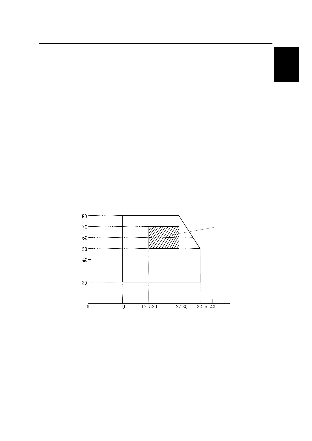
• Likely to encounter wide ranges of temperature and humidity. (Normal operation
environment is within 10 ~ 32.5°C, 20 ~ 80%RH and without condensation.)
• Likely to encounter cold air from an air-conditioner, warm air from a heater, or
direct radiant heat.
• Likely to encounter a lot of dust or exposure to corrosive gases such as
ammonia.
During Operation
Installation
Ambient Humidity (%RH)
Ambient Temperature (°C)
Recommended
Conditions:
17.5 to 27°C
50 to 70%RH
G063I001.WMF
1-1
Page 13
INSTALLATION ENVIRONMENT 17 January, 2001
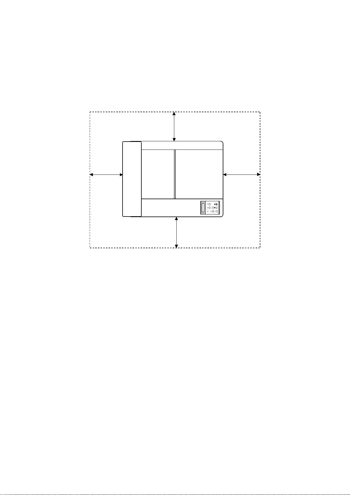
Place the printer:
• Near good ventilation
• On a stable, strong, flat surface.
• With a maximum tilt of 1°.
Make sure to stand the printer on all of its legs. Otherwise, the frame will
warp and belt home position errors will occur.
10 cm (4")
40 cm (16")
Rear
70 cm (28")
Front
10 cm (4")
G063I000.WMF
1-2
Page 14

17 January, 2001 INSTALLATION NOTES
1.2 INSTALLATION NOTES
• For installation procedures, see the Operating Instructions.
• When installing the toner cartridge, do not force it into the machine. Otherwise,
the development roller may be pushed into contact with the OPC belt.
• Make sure that the correct brand name is selected (Refer to 5 - 3 Brand Setting
in the controller manual). This ensures that the correct model name is displayed
on the configuration page and on the LCD.
1.3 RELOCATION PROCEDURE
CAUTION: Observe the following precautions when relocating this unit:
1. This unit requires two or more persons to carry it, because it weighs about
36kg.
2. Keep the unit level during transportation (do not put pressure on any single part
of the base).
3. Whenever possible, use the packing materials shipped with the unit.
4. Carry the unit AFTER removing the following supply parts:
• Fusing Unit Oil Bottle
• Toner Cartridge
• Photoconductor Unit
• Waste Toner Bottle
5. Be sure to protect the photoconductor unit surface with paper.
6. Be sure to remove the following items from various units:
• Silicone oil from the fusing unit oil sump (with a syringe).
• Paper from the cassette
• Optional paper feed unit (remove from the machine)
7. Clean the interior of the unit before re-packing.
8. Secure the front, rear, and top covers with tape so that they do not open and
cassettes can not fall out.
Installation
CAUTION: Since oil and toner will spill if they remain inside the unit if it is carried,
be sure to remove those items and clean the unit before relocating it.
If oil gets on the transfer belt, printouts may be faded.
1-3
Page 15

17 January, 2001 HANDLING PRECAUTIONS
2. PREVENTIVE MAINTENANCE
2.1 HANDLING PRECAUTIONS
Since a high quality laser printer is a precision instrument, daily checks and
periodic maintenance are indispensable to maintain high performance.
The following is a list of important precautions for maintenance and periodic
replacement of parts:
1. Refrain from any operation, disassembly, or modification that is not specified in
this manual.
2. When assembling or disassembling the printer, turn the power supply off first
and be sure to unplug the power supply cord before starting any work.
3. After replacing parts, make sure that the replaced parts are in place before
starting the printer.
4. Carefully read all precautions and warning labels attached to any parts.
5. Unless otherwise specified, precisely follow the reverse order of the
disassembly procedures for re-assembly. Be careful not to confuse the type
and size of removed screws.
6. Do NOT use a solvent to clean any part of the printer.
7. It is strictly forbidden by law to dump or burn waste toner. Follow the
appropriate laws for proper disposal of waste toner in your area.
Preventive
Maintenance
2-1
Page 16

MAINTENANCE BASICS 17 January, 2001
2.2 MAINTENANCE BASICS
2.2.1 CLEANING
Clean the following whenever you visit the customer. Details follow in the ‘Periodic
Cleaning’ section.
• Registration roller
• Transfer roller
• Paper discharger
• Belt cartridge, cleaning blade, charge corona wire
• Dust shield glass (optics unit)
• Inside the printer
2.2.2 REPLACEMENT
Replace the following parts at the stated interval. Details follow in a later section.
• Fusing unit (about 60 k prints, the exact interval depends on the average image
ratio during the life of the part)
• Transfer roller (120 k prints)
• Paper discharger (120 k prints)
• Drum cleaner (120 k prints)
• Paper feed roller and separation pad (120 k prints)
• Transfer drum (300 k images – the same as 120 k prints if the ratio of
monochrome printouts to color printouts is 1:1)
The following gives an outline of the maintenance procedure, and how to use both
the controller and engine SP modes dur i ng mai nte nance.
!
CAUTION
When turning off the unit to perform periodic maintenance, make sure that
no data has been sent to the printer.
1. Enter controller SP mode and print a configuration page (user menu),
maintenance page (S1), and a color chart (S2). The configuration page is
required to restore the settings if they are altered during maintenance. Refer to
the controller service manual for how to use controller SP modes.
2. Perform the periodic maintenance and cleaning procedures as instructed in the
Periodic Maintenance – Periodic Cleaning section of this manual.
3. Examine the color chart to check the densities of the solid images and the
grayscales in the images with gradations. If an anomaly is found, check the
engine (see ‘4.Troubleshooting – 4.5 Imaging’ in this manual).
4. If the “Change Fuser” and/or “Change 120K” message appears, replace the
fusing unit and/or the parts in the 120k maintenance kit.
Then, use either controller SP mode S3 (Maint. Clear) or engine SP mode 36
(Clear Care) to reset the counters for the fusing unit and 120k kit.
For details on the replacement items and procedures, refer to ‘2. Preventive
Maintenance – 2.4 Periodic Replacement’ in this manual).
2-2
Page 17

17 January, 2001 PERIODIC CLEANING
2.3 PERIODIC CLEANING
2.3.1 OVERVIEW
!
WARNING
Before starting any cleaning, unplug the printer.
There is a risk of electric shock in working while the printer is energized.
Name of Part Cleaning Symptoms Prevented
Registration
Roller
Transfer Roller
Paper
Discharger
1. Open the transfer unit
2. Clean the roller and neighboring areas
with a dry cloth.
1. Open the transfer unit.
2. Clean the roller and neighboring areas
with a dry cloth.
1. Open the transfer unit.
2. Remove the paper discharge unit.
Defective print quality
Smeared paper
Defective print quality
Smeared paper
Defective print quality
Paper jam
Preventive
Maintenance
Belt Cartridge
Optical Unit
Dust Shield
Glass
Printer Interior
3. Clean the corona wire and case with a
cotton bud or dry cloth.
1. Remove the belt cartridge.
2. Clean off the toner around the belt
cartridge and cleaning blade.
3. Clean the charge corona wire with a
wire brush.
1. Remove the toner cartridge.
2. Remove the belt cartridge.
3. Remove the dust shield glass.
4. Using a dry cloth or cotton bud, clean
off any stains on the dust-proof glass.
1. Remove the toner and belt cartridges.
2. Clean the base of the printer with a
vacuum cleaner and wipe it with a dry
cloth.
Defective print quality
Defective print quality
Defective print quality
2-3
Page 18

PERIODIC CLEANING 17 January, 2001
2.3.2 DAILY MAINTENANCE
There is no part in the standard or optional paper feed units that requires daily
maintenance, such as cleaning etc.
2.3.3 PERIODIC MAINTENANCE
There is no part in the standard or optional paper feed units that requires periodic
replacement. However, it is recommended for good paper feed performance to
replace the following parts in accordance with the periodic replacement cycle
based on the counter of the main engine.
Part Name Part Code Replacement Cycle
Paper Feed Roller 126142
Separator Pad (2) * 126528
*: ‘Separator Pad (2)’ is a part name. The ‘2’ does not indicate the quantity; there is
only one separator pad in the main engine paper feed section. There is another
pad, with the same name, in the optional paper feed unit.
Every 120k prints
2-4
Page 19
17 January, 2001 PERIODIC CLEANING
2.3.4 PROCEDURES
(1) Registration Roller Cleaning
[A]
[B]
G063P011.WMF
Preventive
Maintenance
[A]
[B]
G063P008.WMF
Materials
1. Dry cotton cloth (2 ~ 3 pieces)
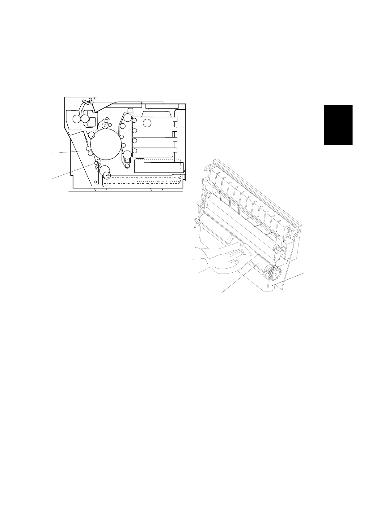
Cleaning Procedure
1. Turn off the power supply, and unplug the power cord.
2. Open the transfer unit [A].
3. Using the cotton cloth, clean the registration roller [B] in the transfer unit.
CAUTION: Do NOT use alcohol or a similar solvent to clean the registration roller.
2-5
Page 20
PERIODIC CLEANING 17 January, 2001
(2) Transfer Roller Cleaning
[A]
[B]
G063P011.WMF
[B]
[A]
G063P009.WMF
Materials
1. Dry cotton cloth (2 ~ 3 pieces)
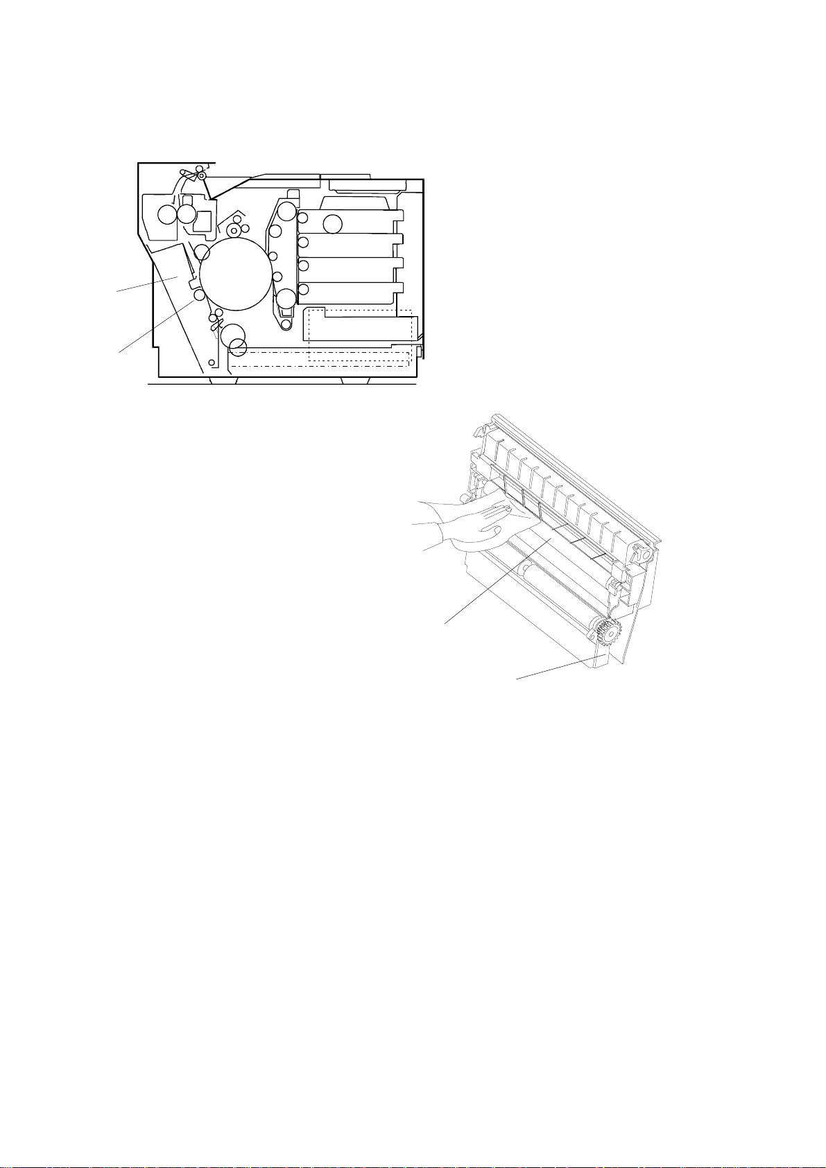
Cleaning Procedure
1. Turn off the power supply, and unplug the power cord.
2. Open the transfer unit [A].
3. Using a cotton cloth, clean the transfer roller [B].
CAUTION: Do not use alcohol or a similar solvent to clean the transfer roller.
2-6
Page 21
17 January, 2001 PERIODIC CLEANING
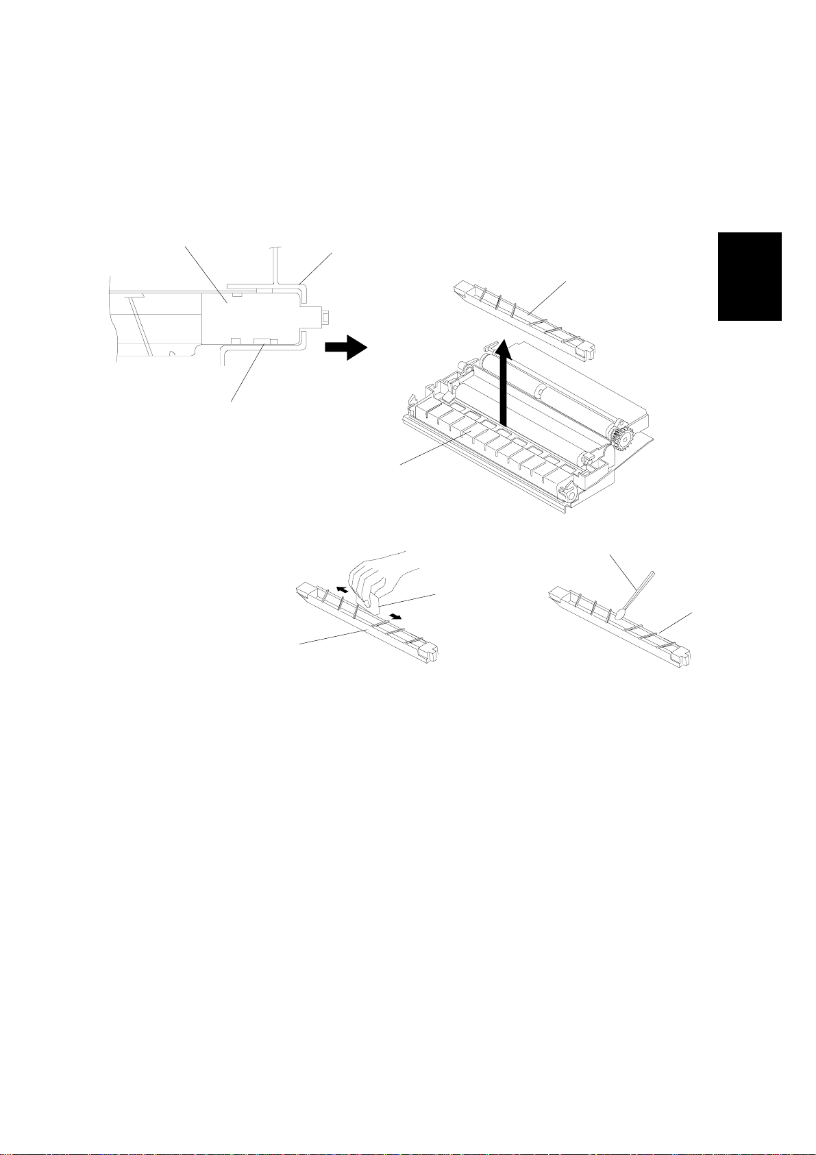
(3) Paper Discharger Cleaning (AC Corona Unit)
Materials
1. Dry cotton cloth (2 to 3 pieces).
2. Cotton buds (2 to 3)
[C]
[D]
[E]
G063P010.WMF
[A]
[G]
[B]
[I]
[H]
Preventive
Maintenance
[F]
G063P002.WMF
Cleaning Procedure
1. Turn off the power, and unplug the machine.
2. Open the transfer unit [A].
3. Remove the paper discharger unit [B].
1) Slide the AC corona unit [C] in the direction of the arrow, and release it from
the locking claw [D].
2) Pull up the AC corona unit to remove it from the transfer unit holder [E].
4. Clean the case [F] with a cotton cloth [G].
5. Clean the corona wire [H] and inside the case with a cotton bud [I].
CAUTION: Do not break the corona wire when cleaning the paper discharger unit.
2-7
Page 22
PERIODIC CLEANING 17 January, 2001
(4) Photoconductor Unit (Belt Cartridge) Cleaning
CAUTION: 1) Do NOT expose the OPC belt to more than 800 luxes of light (i.e.,
ordinary office light) for more than two minutes.
2) Do NOT touch the surface of the OPC belt.
NOTE: The photoconductor unit is sometimes referred to in the documentation as
the ‘belt cartridge’.
Materials
1. Clean cotton cloth (2 ~ 3 pieces)
[D]
[C]
[A]
G063R575.BMP
e
d
i
l
S
[B]
G063R031.WMF
2-8
Page 23

17 January, 2001 PERIODIC CLEANING
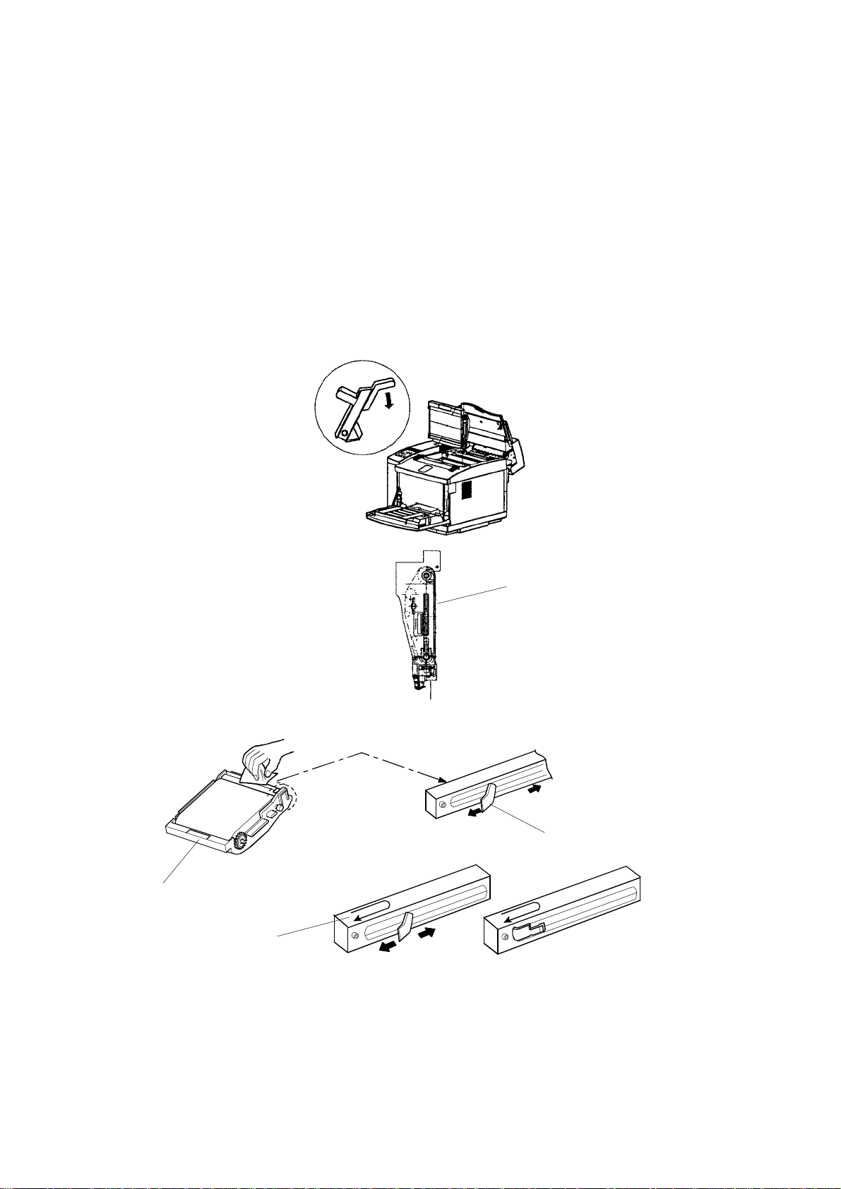
Cleaning Procedure
1. Turn off the power supply switch.
2. Open the paper exit cover.
3. Open the front cover unit.
4. Release the lock mechanism for the belt cartri dg e.
5. Pull out the belt cartridge [A].
6. Clean the belt cartridge with a cotton cloth.
1) Clean the rear of the belt cartridge.
2) Holding the wire cleaner [B] attached to corona case, slide the wire cleaner
to left and right for several times along the corona case [C]. After completing
this operation, put the wire cleaner back to the original position.
3) Clean the belt cartridge case [D].
CAUTION: Take care NOT to break the corona wire when cleaning it.
Preventive
Maintenance
2-9
Page 24
PERIODIC CLEANING 17 January, 2001
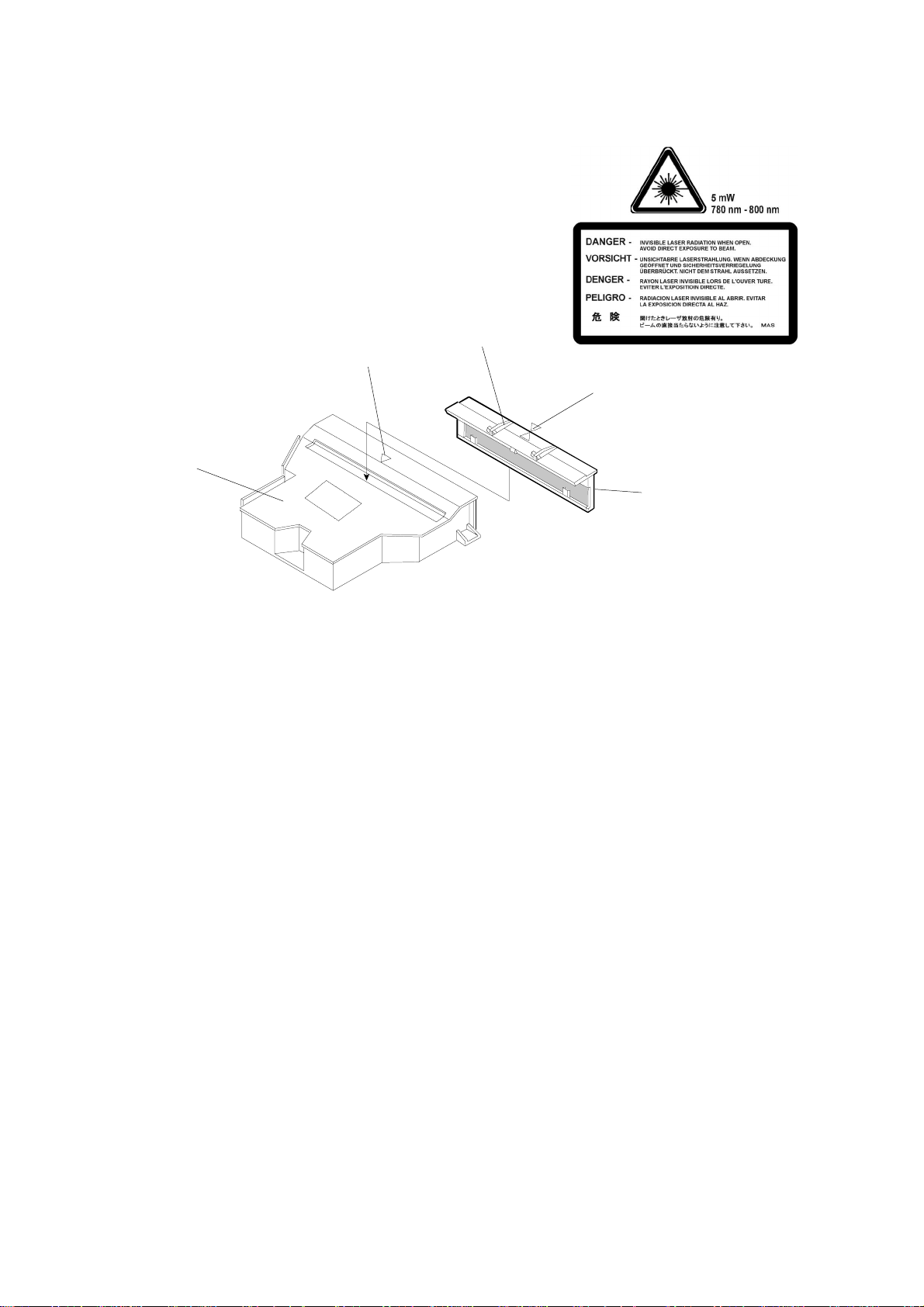
(5) Optics Unit Dust Shield Glass Cleaning
Materials
1. Dry cotton cloth (2 ~ 3 pieces)
2. Cotton buds (2 ~ 3)
[E]
[C]
Cleaning Procedure
1. Turn off the power supply switch.
2. Open the paper exit cover.
3. Open the front cover unit.
[A]
LASER2.TIF
[D]
[B]
G063P004.WMF
4. Remove the toner cartridges.
5. Remove the belt cartridge.
6. Holding the knobs [A] on the glass frame [B], carefully remove it from the
optical unit [C].
7. Clean the surface of the glass with a cotton bud or cloth.
Reinstallation
NOTE: Align the triangle mark on the glass [D] with the similar mark [E] on the
optical unit, then push the dust shield glass in until it is firmly locked.
CAUTION: Do NOT use alcohol or a similar solvent to clean the glass, or print
quality will deteriorate.
2-10
Page 25

17 January, 2001 PERIODIC CLEANING
(6) Printer Interior Cleaning
[B]
[A]
G063P005.WMF
Materials
Preventive
Maintenance
1. Compact vacuum cleaner, specially designed for vacuuming toner [A]
2. Dry cotton cloth (2 to 3 pieces)
Cleaning Procedure
1. Open the paper exit cover.
2. Open the front cover.
3. Remove the toner cartridge.
4. Remove the belt cartridge.
5. Vacuum toner scattered on the bottom of the printer interior [B]
6. Clean the printer interior with a cotton cloth.
7. Put back the removed units.
2-11
Page 26

PERIODIC REPLACEMENT 17 January, 2001
2.4 PERIODIC REPLACEMENT
2.4.1 OVERVIEW
Component Cycle
Fusing Unit 60k prints *1
Transfer Roller 120k prints
Paper Discharge Unit 120k prints
Drum Cleaner 120k prints
Paper Feed Roller/Separat ion Pad 120k prints
Transfer Drum 300k images. *2
*1: The machine calculates the fusing unit replacement cycle from the image
ratio. The greater the image ratio, the shorter the cycle.
Example: If the image ratio is 5% for each color, the total image ratio is 20%
for all four colours. The machine will ask the user to repla c e the fusing unit
after 50k copies (this value is 60k if the image ratio is less than 12.5%). See
section 5.5.3 for details on how the machine changes the replacement cycle
depending on image ratio.
*2: The image count is 1 for one monochrome print and 4 for a full color print. If
the user makes monochrome and full color prints at a ratio of 1:1 on average,
the image count per sheet (averaged out) is 2.5. In this condition, 300 k
images is the same as 120 k prints.
After replacing a part, reset the maintenance counters as explained in each
procedure.
2-12
Page 27
17 January, 2001 PERI O DI C REPLACEMENT
Fusing Unit Replacement
(1) Replacement Criteria
Replace when this error message appears on
the operation panel LCD.
IPDL-C
Change Fuser
(2) Purpose of Replacement
To prevent print quality decline caused by fusing unit roller wear.
(3) Precaution
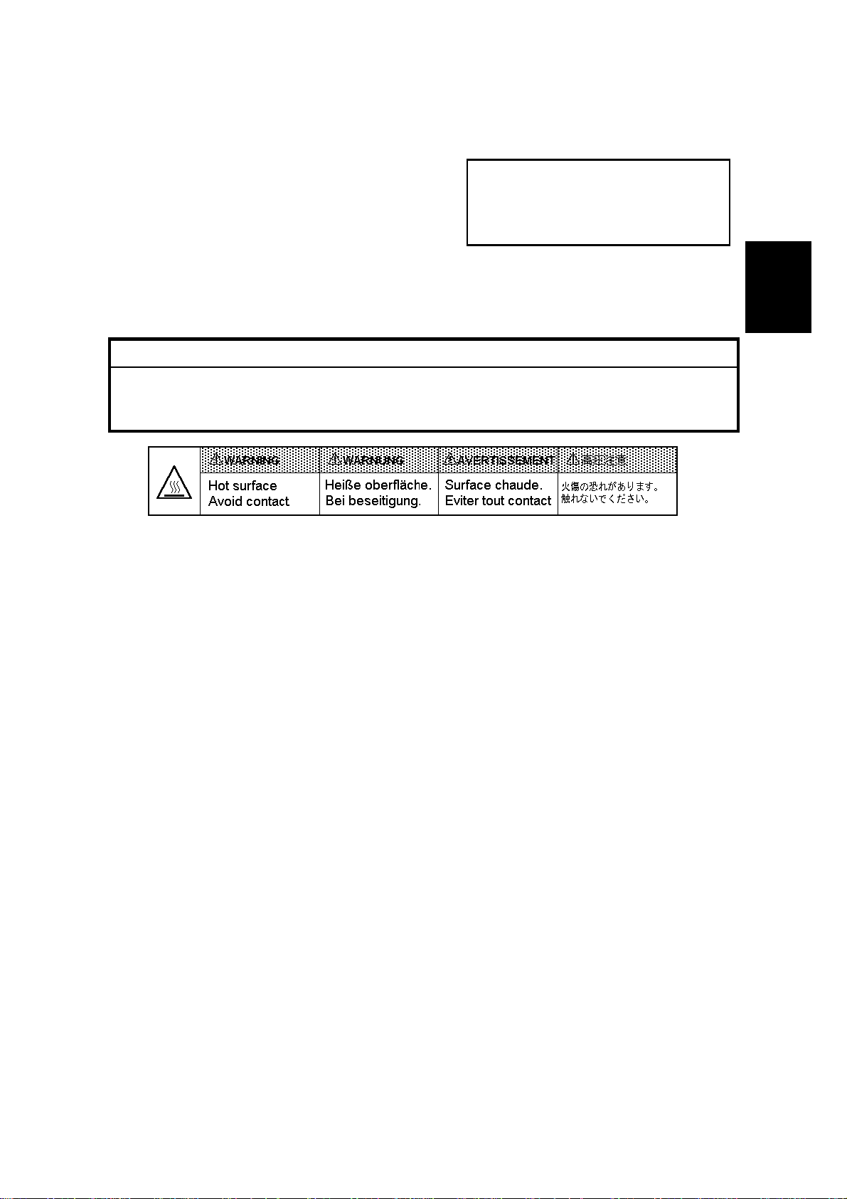
!
WARNING
The fusing unit and surrounding parts are very hot. Make sure, prior to
starting replacement, that the fusing unit and surrounding parts are cool,
otherwise, you may get burned.
HOT.BMP
(4) Necessary tools and replacement materials
1. Two or three pieces of cotton cloth.
2. New fusing unit
Preventive
Maintenance
2-13
Page 28
PERIODIC REPLACEMENT 17 January, 2001
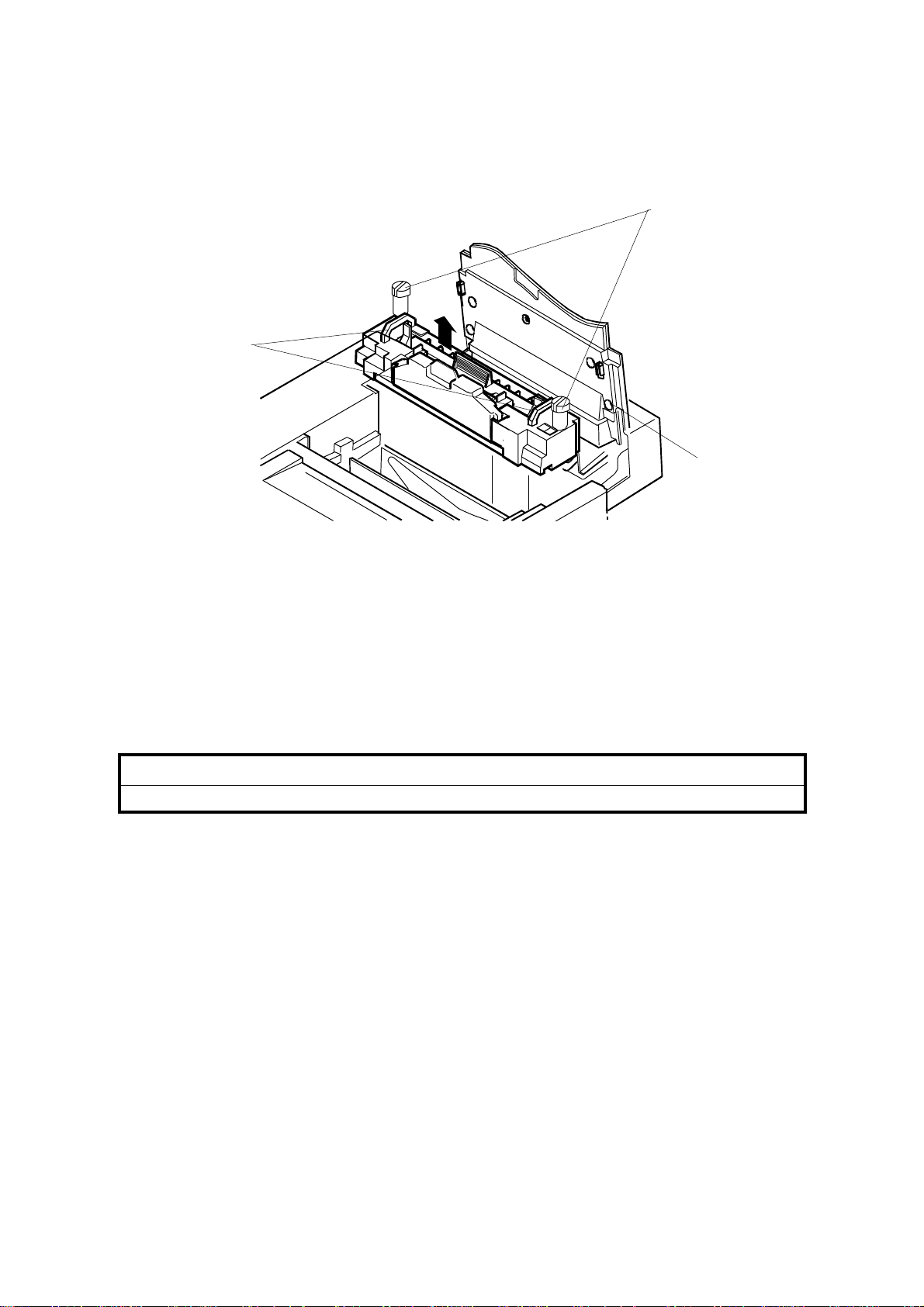
(5) Procedure
- Disassembly [B]
[C]
[A]
G063R034.WMF
1. After turning the power off, unplug the machine.
2. Open the paper exit unit [A].
3. Loosen the screws.
1) Place a sheet of paper over the transfer drum surface to protect it.
2) Loosen the screws [B] at both left and right sides.
4. Holding the handles [C] at both sides of the fusing unit, remove the fusing unit.
!
CAUTION
When removing the fusing unit, keep it level so that oil does not leak.
2-14
Page 29
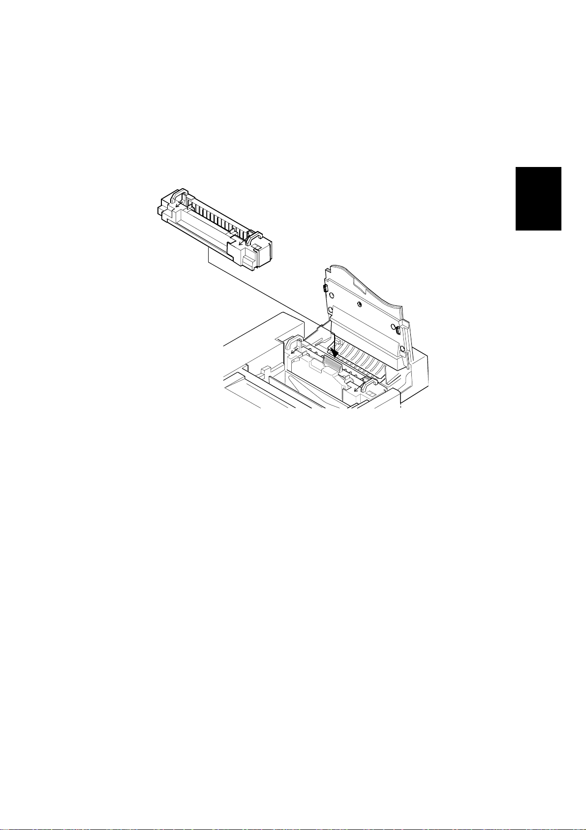
17 January, 2001 PERI O DI C REPLACEMENT
NOTE: Before installing a new fusing unit, restore the tension-release levers (left
and right side) in the arrow direction.
Preventive
Maintenance
G063R035.WMF
2-15
Page 30
PERIODIC REPLACEMENT 17 January, 2001
Transfer Roller Replacement
(1) Replacement Criteria
When it is time to replace the transfer roller,
an error message appears on the operati on
panel LCD.
IPDL-C
Change 120K
(2) Replacement Purpose
Prevents transfer efficiency from declining due to transfer roller wear.
(3) Necessary tools and replacement materials
1. Two or three pieces of cotton cloth for cleaning.
2. New transfer roller
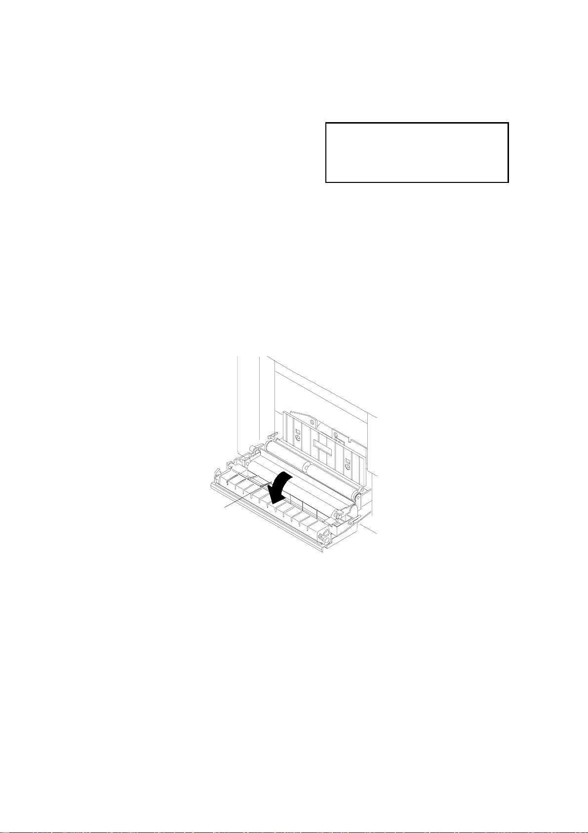
(4) Procedure
[A]
G063P021.WMF
- Disassembly -
1. After turning the power off, unplug the machine.
2. Open the lower rear cove r [A].
2-16
Page 31

17 January, 2001 PERI O DI C REPLACEMENT
- Replacement -
[B]
[A]
G063P025.WMF
Preventive
Maintenance
1. Release the lock lever [A] for the transfer roller [B] by turning it in the arrow
direction.
NOTE: The roller can only be removed when the lever is about 70 ° from the
horizontal.
2. Remove the transfer roller.
1) After lifting up the right end of the transfer roller, slide it to the right.
3. Put the new transfer roller into the printer.
1) Fit the projecting shaft into the hole at the left end.
2) Fit the lock lever shaft into the recessed hole at the right end.
NOTE: Be sure that the spring is upright (see below).
G063P028.TIF
4. Lock the transfer roller down by turning the lock lever in the opposite direction
to the arrow.
2-17
Page 32

PERIODIC REPLACEMENT 17 January, 2001
- Assembly -
1. Close the lower rear cover.
2. Plug in the printer.
3. Turn the power on.
4. After the machine completes the warm-up process, clear the maintenance
counter for 120k maintenance using controller SP mode S3 (Maintenance
Clear) or engine SP mode 36 (Clear Care).
Paper Discharger Replacement
(1) Replacement Criteria
When it is time to replace the paper
discharger, an error message appears on the
operation panel LCD.
IPDL-C
Change 120K
(2) Replacement Purpose
Prevents paper discharger efficiency from declining.
(3) Precaution
CAUTION: Do NOT touch the corona wire in the paper discharger unit.
(4) Necessary tools and replacement materials
1. Two or three pieces of cotton cloth.
2. New paper discharger unit
(5) Procedure
- Disassembly -
1. After turning the power off, unplug the machine.
2. Open the lower rear cover.
2-18
Page 33

17 January, 2001 PERI O DI C REPLACEMENT
- Replacement -
[A]
Preventive
Maintenance
G063P019.WMF
1. Remove the paper discharger from the transfer unit [A].
2. Clean the area where the new paper discharger will be mounted.
3. Install the new unit in the transfer unit.
- Assembly -
1. Close the lower rear cover.
2. Plug in the printer.
3. Turn the power on.
4. After the machine completes the warm-up process, clear the maintenance
counter for 120k maintenance using controller SP mode S3 (Maintenance
Clear) or engine SP mode 36 (Clear Care).
2-19
Page 34

PERIODIC REPLACEMENT 17 January, 2001
Drum Cleaning Unit Replacement
(1) Replacement Criteria
When it is tim e to replace the drum cleaning unit, an error message appears on the
operation panel LCD.
(2) Replacement Purpose
Prevents loss of drum cleaning efficiency.
IPDL-C
Change 120K
(3) Precaution
CAUTION: When installing the drum cleaning unit, first connect the shaft and the
bias terminal (see the diagram on the next page). Check this
connection after installation.
(4) Necessary tools and replacement materials
1. Two or three pieces of cotton cloth.
2. New drum cleaning unit
(5) Procedure
- Disassembly -
1. Turn the power off.
2. Open the paper exit cover.
2-20
Page 35

17 January, 2001 PERI O DI C REPLACEMENT
- Replacement -
[A]
[B]
Preventive
Maintenance
[C]
[B]
G063P007.WMF
1. Remove the drum cleaning unit cover [A].
2. Holding the handle [B] on top of the drum cleaning unit [C], remove the drum
cleaning unit.
1) Turn the handle [B] in the center in the direction of the arrow to disconnect
the drum cleaning unit shaft from the bearing.
3. Clean the area where the new unit will be mounted.
4. Put the new drum cleaning unit into the printer.
2-21
Page 36

PERIODIC REPLACEMENT 17 January, 2001
- Assembly -
1. Install the drum cleaning unit cover.
2. Close the paper exit cover.
3. Turn the power on.
4. After the machine completes the warm-up process, clear the maintenance
counter for 120k maintenance using controller SP mode S3 (Maintenance
Clear) or engine SP mode 36 (Clear Care).
Paper Feed Roller and Separation Pad Check
(1) Replacement Criteria
Replace these when an error message is
displayed on the LCD or when paper feed
jams occur.
IPDL-C
Change 120K
(2) Replacement Procedure
1. Whene ver a paper feed jam occurs, determ ine the cause of the error. See
"Troubleshooting - Paper Transportation Error".
2. If the jam is caused by a defective paper feed roller or separation pad, replace
the defective part as explained in the Replacement Procedures section.
CAUTION: 1) This cannot be done by the customer. These items should be
replaced on customer request or during periodic maintenance.
2) After the replacement, check to make sure that the different types of
media such as plain paper, OHP, and thick paper, move through the
printer correctly.
2-22
Page 37

17 January, 2001 PERI O DI C REPLACEMENT
Transfer Drum Replacement
(1) Replacement Criteria
Replace this when the error message
appears on the LCD or when print quality is
poor because of a defective transfer drum.
IPDL-C
Change 120K
(2) Replacement Procedures
1. Whenever defective print quality occ urs, check the cause in accordance with
the "4. Troubleshooting - Imaging Failure" section.
2. If the transfer drum caused the failure, replace it as described in the
Replacement Procedures section.
CAUTION: 1) This cannot be done by the customer. Replace this part on customer
demand or during periodic maintenance.
2) After replacement, make a test print to check whether the print
quality has improved.
Preventive
Maintenance
2-23
Page 38

17 January, 2001 COVERS
3. REPLACEMENT AND ADJUSTMENT
3.1 COVERS
3.1.1 LEFT UPPER SIDE COVER
[B]
Open the paper exit cover [A].
[B]: Left Upper Side Cover (! x1)
NOTE: Pressing the exterior of the left
side cover [C], unlock three hooks
[D] on the left upper side cover.
[A]
Adjustment
Replacement
PUSH
G063R507.WMF
[D]
[C]
G063R508.WMF
3-1
Page 39

COVERS 17 January, 2001
3.1.2 RIGHT SIDE COVER AND OZONE FILTER COVER
Open the front cover [A].
[A]: Right Side Cover (! x1)
NOTE: While slightly lifting the rear
right part of the top cover [C],
slide the side cover in the
arrow direction.
[D]: Ozone Filter Cover
[B]
[A]
G063R510.WMF
[D]
[C]
G063R511.WMF
3-2
Page 40

17 January, 2001 COVERS
3.1.3 LEFT SIDE COVER
☛3.1.1 Left Upper Side Cover
[A]: Left Side Cover (! x 2).
NOTE: Slowly and carefully pull up the
cover
Adjustment
Replacement
[A]
G063R509.WMF
3-3
Page 41

COVERS 17 January, 2001
3.1.4 FRONT LEFT SIDE COVER
☛ 3.1.1 Left Upper Side Cover
☛ 3.1.3 Left Side Cover
[A]: Front Left Side Cover (! x 1)
NOTE: Slightly lifting up the front
left part of the top cover [B],
pull up the front left side
cover and unhook the hook
[C] from the frame.
[A]
[B]
[C]
G063R513.WMF
3-4
Page 42

17 January, 2001 COVERS
3.1.5 TOP COVER
☛ 3.1.1 Left Upper Side Cover
☛ 3.1.2 Right Side Cover
[A]: Top Cover (! x 2)
[A]
Adjustment
Replacement
G063R512.WMF
3-5
Page 43

COVERS 17 January, 2001
3.1.6 PAPER EXIT FRONT COVER / PAPER EXIT COVER ASS’Y
☛ 3.6.6 Paper Exit Unit
[A]: Paper Exit Front Cover (! x 4)
[B]: Paper Exit Cover Ass’y (! x 4)
[B]
[A]
G063R516.WMF
3-6
Page 44

17 January, 2001 COVERS
3.1.7 LOWER REAR COVER (TRANSFER COVER)
☛ 3.6.1 Transfer Unit
[A]: Lower Rear Cover (! x 4)
Adjustment
Replacement
[A]
G063R501.WMF
3-7
Page 45

COVERS 17 January, 2001
3.1.8 LOWER REAR COVER
Unplug the power cable from the machine’s ac inlet.
[A]: Lower Rear Cover (! x 1)
[A]
G063R515.WMF
3-8
Page 46
17 January, 2001 COVERS
3.1.9 UPPER REAR COVER
☛ 3.1.2 Right Side Cover
☛ 3.1.8 Lower Rear Cover
[A]: Upper Rear Cover with Rear Cover Cap [C].
NOTE: Unhook the hooks [B] (2
locations) on the upper rear cover
from the frame.
[C]
[A]
Adjustment
Replacement
[B]
G063R514.WMF
3-9
Page 47

COVERS 17 January, 2001
3.1.10 RIGHT BASE COVER
☛ 3.1.2 Right Side Cover
[A]: Right Base Cover (! x 2)
1) Pull out the rear side.
2) Pull out the front side.
[A]
G063R517.WMF
NOTE: 1) When assembling th e base cover [C], insert the leading edge of the
base cover over the hooks [B] (2 locations) provided at the bottom (left
and right) of the base plate [C].
2) Have the hooks [D] on the base cover meet the holes [E] (2 locations) in
the base plate bottom.
[C]
[D]
[B]
[E]
G063R518.WMF
3-10
Page 48

17 January, 2001 COVERS
3.1.11 LEFT BASE COVER
☛ 3.1.3 Left Side Cover
[A]: Left Base Cover (! x 2)
1) Pull and remove the rear side.
2) Pull and remove the front
side.
[A]
Adjustment
Replacement
G063R505.WMF
NOTE: 1) When assembling the left base cover [C ], insert the leading edge of the
base cover over the hook [B] (2 locations) provided at the bottom (left
and right) of the base plate [C].
2) Have the hooks [D] on the base cover meet the holes [E] (2 locations) in
the base plate bottom.
[C]
[E]
[D]
[B]
G063R519.WMF
3-11
Page 49

COVERS 17 January, 2001
3.1.12 CLEANER COVER
Open the Paper Exit Cover [A].
Holding the tabs [B], remove the Cleaner Cover [C].
[C]
[B]
[C]
[A]
G063R506.WMF
3-12
Page 50

17 January, 2001 COVERS
3.1.13 FRONT COVER
Open the front cover unit [A].
[B]: Front Cover (! x 2)
NOTE: Unhook the hooks (3 at left and
1 at right), and remove the front
cover from the front cover unit.
Adjustment
Replacement
[A]
G063R502.WMF
[B]
3-13
Page 51

PCBS 17 January, 2001
3.2 PCBS
3.2.1 PCB LAYOUT
1
2
7
6
3
4
5
G063R520.WMF
1
Quenching Lamp
2
IOD2
3
IOD1
4
MCTL
5
6
7
Power Supply Unit
High Voltage Unit
Panel Board
For the controller board, see the separate controller service manual.
NOTE: When replacing PCBs, take care that no damage occurs from static
electricity.
3-14
Page 52

17 January, 2001 PCBS
3.2.2 MCTL
NOTE: If possible, make a note of the current NVRAM settings before starting (see
Service Tables: 46. NVRAM INITIAL).
☛ 3.1.3 Left Side Cover
[A]: Shield Cover (! x 1)
Disconnect all the connectors on the MCTL [B].
[B]: MCTL (! x 4)
NOTE: After re-assembly, do the following:
1. Turn on the power switch while holding the [Menu], [Enter], and ["] keys to
access Service Mode.
2. Execute service mode 46 to clear the contents of the RAM.
3. Using service mode, input the values that were in the old RAM into the new
RAM.
4. Check the operation and print quality by making a test print.
Adjustment
Replacement
3-15
Page 53

PCBS 17 January, 2001
[B]
[A]
G063R527.WMF
3-16
Page 54

17 January, 2001 PCBS
3.2.3 IOD 1
☛ 3.1.1 Left Upper Side Cover
☛ 3.1.5 Top Cover
[A]: Shield Cover (! x 4)
[B]: IOD1 (! x 6, " x 16)
NOTE: When replacing the IOD1 ,
take care that no damage
occurs from static electricity.
[A]
Adjustment
Replacement
[B]
G063R526.WMF
3-17
Page 55

PCBS 17 January, 2001
3.2.4 IOD2
☛3.1.2 Right Side Cover
[A]: IOD2 (! x 5, " x 16)
NOTE: When replacing the IOD2, take care that no damage occurs from static
electricity.
G063R524.WMF
[A]
3-18
Page 56
17 January, 2001 PCBS
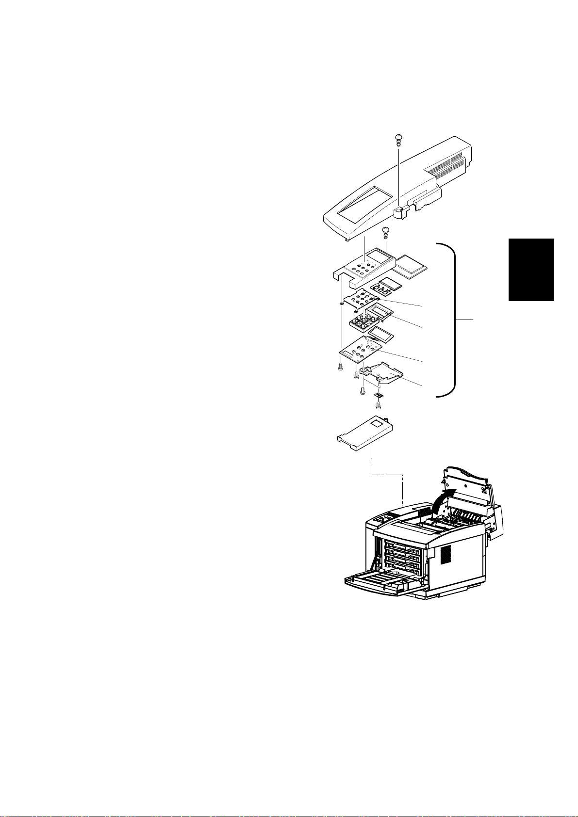
3.2.5 PANEL BOARD (INCLUDING LCD)
☛3.1.1 Left Upper Side Cover
Panel Case Assembly [A]: (! x 1,#" x 1)
Panel Board [B]: (! x 4)
Upon removal of the panel board, the shield
plate [C], panel buttons [D], and panel shield
[E] can be removed.
[E]
[A]
[D]
Adjustment
Replacement
[B]
[C]
G063R529.WMF
3-19
Page 57

PCBS 17 January, 2001
3.2.6 POWER SUPPLY UNIT
[C]
[A]
[B]
[D]
[E]
[G]
G063R521.WMF
[F]
[H]
3-20
Page 58

17 January, 2001 PCBS
☛3.1.1 Left Upper Side Cover
☛3.1.3 Left Side Cover
☛3.1.4 Front Left Side Cover
☛3.1.11 Left Base Cover
☛3.1.8 Lower Rear Cover
[A]: Shield Cover 2 (! x 1)
[B]: Shield Cover 1 (! x 2)
[C]: Shield Cover F (! x 2)
Remove the switch button and switch holder from the remote switch located at the
front of the machine.
Disconnect all the cables connected to the MCTL.
[D]: Controller Fan Assembly (! x 1)
[E]: Shield Case A Assembly (! x 5)
[F]: Left Bottom Stay (! x 2)
Disconnect the 5 cables connected to the power supply unit.
[G]: Inlet (! x 2)
[H]: Power supply unit (! x 2)
• Pull out the front part.
• Unhook the hook from the hole in
the base frame.
• Remove the power supply unit 2
from the engine.
[G]
!
CAUTION
G063R528.WMF
Adjustment
Replacement
Grounding wires are very important to secure the safety of users. Upon
removal of the power supply unit, confirm that the grounding wires (green
and yellow) are securely connected to the required parts.
3-21
Page 59

PCBS 17 January, 2001
3.2.7 HIGH VOLTAGE UNIT
☛3.1.1 Left Upper Side Cover
☛3.1.3 Left Side Cover
[A]: Shield Cover 2 (! x 1)
[B]: Shield Cover 1 (! x 2)
Disconnect the cables connected to the MCTL (6 locations).
[C]: Controller Fan Assembly (! x 1)
[D]: Shield Case A Assembly (! x 4)
Disconnect all the cables connected to the high voltage unit (3 locations).
[E]: High Voltage Unit (! x 9)
!
WARNING
The High Voltage Unit generates a high voltage (5KV). You may get an
electric shock if you touch the unit while the power switch is on. Therefore,
turn on the unit ONLY after installing the left side cover.
3-22
Page 60

17 January, 2001 PCBS
[A]
[B]
[C]
[D]
Adjustment
Replacement
[E]
G063R525.WMF
3-23
Page 61

PCBS 17 January, 2001
3.2.8 ERASE LAMP
Open the front cover.
Open the paper exit unit.
Pull out the toner cartridges (K/M/C/Y).
Pull up the belt cartridge.
[A]: Erase Lamp (" x 1).
NOTE: Do not touch the transfer drum
with your bare hands wh ile
removing or reassembling the
erase lamp.
[A]
G063R523.WMF
NOTE: The erase lamp has directional characteristics. If it is installed the wrong
way around, the transfer drum may be damaged.
Hole
Left Side
Hole
G063R522.WMF
Hole
Right Side
3-24
Page 62

17 January, 2001 MOTORS
3.3 MOTORS
3.3.1 MOTOR LAYOUT
6
5
4
1
2
Adjustment
Replacement
3
G063R530.WMF
1
Main Motor
2
Development Motor
3
Polygonal Mirror Motor
3-25
4
5
6
Controller Fan
Fusing Unit Fan
Ozone Fan
Page 63

MOTORS 17 January, 2001
3.3.2 MAIN MOTOR / GEAR ASS”Y
☛3.1.2 Right Side Cover
☛3.1.5 Top Cover
Remove the cable connected to the main motor.
Remove all cables connected to the IOD2.
[A]: IOD2 Base Unit (! x 2)
[B]: Gear Ass’y (! x 3)
[C]: Main Motor (! x 4)
[A]
[B]
[C]
G063R531.WMF
3-26
Page 64

17 January, 2001 MOTORS
3.3.3 MAIN DRIVE UNIT
• Gear Ass’y (☛3.3.2 Main Motor / Gear A)
Remove the fusing unit.
[A]: Main Drive Unit (! x 4)
Adjustment
Replacement
G063R532.WMF
[A]
3-27
Page 65

MOTORS 17 January, 2001
3.3.4 DEVELOPMENT MOTOR
☛ 3.1.5 Top Cover
Remove the toner cartridges.
Disconnect the connector CN1 connected to the developer motor
[A]: Development Motor (! x 4)
G063R533.WMF
[A]
3-28
Page 66

17 January, 2001 MOTORS
3.3.5 DEVELOPMENT DRIVE UNIT
Remove the toner cartridges.
Remove the waste toner bottle.
☛3.1.5 Top Cover
☛3.1.10 Right Base Cover
[A]: Cover RF (! x 1)
[B]: IOD2 Base Assy (! x 2)
[C]: WT Holder Assy (! x 2)
☛3.3.4 Development Motor
[D]: Washers (4pcs.) for Development Drive Gear
[E]: Development Drive Gear
[F]: Development Drive Unit (! x 4)
[B]
Adjustment
Replacement
[A]
[D]
[E]
[C]
[F]
G063R534.WMF
3-29
Page 67

MOTORS 17 January, 2001
3.3.6 OPTICAL UNIT (INCLUDING POLYGONAL MIRROR MOTOR)
Remove the toner cartridges.
Remove the belt cartridge (photoconductor unit).
[A]: Optical Unit Cover
NOTE: The optics unit cover is fixed by plastic projections [B] on the front side
and slots [C] on the rear side.
1) Release three slots at the rear.
2) Release two locks at the front while pulling the cover toward you.
3) Remove the cover from the printer.
[D]: Optical Unit (! x 4, " x 1)
[B]
[D]
[A]
[C]
G063R540.WMF
!
WARNING
1. There is a Class B laser within the optical unit. Do not attempt to
disassemble the laser.
2. The optical unit is replaced as a whole unit. No adjustment is required
to the new optical unit.
3. Confirm that all the covers have been installed prior to any test run or
operation in order to prevent any laser radiation from escaping.
3-30
Page 68

17 January, 2001 MOTORS
3.3.7 CONTROLLER FAN
☛3.1.1 Left Upper Side Cover
☛3.1.3 Left Side Cover
☛3.1.5 Top Cover
[A]: Upper Shield Cover(! x 4)
[B]: Control Fan Case Assy (! x 2, " x 1)
[C]: Controller Fan
[A]
G063R535.WMF
[B]
NOTE: Open the fan case (unhook at one
location), and remove the fan
motor (the interlock switch top is
also removed.)
The interlock switch must be
installed properly
Adjustment
Replacement
3-31
[C]
G063R537.WMF
Page 69

MOTORS 17 January, 2001
3.3.8 FUSING UNIT FAN
• Paper Exit Cover (☛3.1.6 Paper Exit Front Cover / Paper Exit Cover Ass’y)
[A]: Heater Fan Case Assembly (" x 1)
NOTE: 1) This assembly is attached to the Paper Exit Frame Assembly [B] with a
hook.)
2) When in stalling the fucing unit fan , make sure that rating label on the fan
motor faces the exhaust side.
[A]
[B]
[A]
G063R538.WMF
3-32
Page 70

17 January, 2001 MOTORS
3.3.9 OZONE FAN
☛3.1.2 Right Side Cover and Ozone Filter
Cover
☛3.1.10 Right Base Cover
☛3.2.4 IOD2
• WT Holder Ass’y (☛3.3.5 Development
Drive Unit)
[A]
G063R539.WMF
[A]: Ozone Fan Case (! x 1)
Open the Ozone Fan Case and remove the Ozone Fan [B].
[B]
G063R536.WMF
Adjustment
Replacement
3-33
Page 71

CLUTCHES AND SOLENOIDS 17 January, 2001
3.4 CLUTCHES AND SOLENOIDS
3.4.1 CLUTCH AND SOLENOID LAYOUT
1
2
3
4
5
1
Drum Cleaner Clutch
2
Fusing Clutch
3
Cleaning Clutch
4
Transfer Clutch
5
Registration Clutch
6
7
8
9
10
7
8
9
10
G063R541.WMF
Paper Feed Clutch
Development Clutch (K)
Development Clutch (Y)
Development Clutch (M)
Development Clutch (C)
6
3-34
Page 72

17 January, 2001 CLUTCHES AND SOLENOIDS
3.4.2 FUSING / CLEANING / REGISTRATION CLUTCH
• Right Side Cover (☛3.1.2 Right Side Cover and Ozone Filter Cover)
1. Disconnect the connector for the applicable clutch from the IOD2.
2. Remove the washer of the applicable clutch from the shaft.
3. Pull the clutch off the shaft.
[A]: Fusing Clutch
[B]: Cleaning Clutch
[C]: Registration Clutch
Adjustment
Replacement
[B]
[A]
[C]
G063R542.WMF
3-35
Page 73

CLUTCHES AND SOLENOIDS 17 January, 2001
3.4.3 PAPER FEED CLUTCH
☛3.2.4 IOD2
[A]: Paper feed clutch washer
[B]: Paper Feed Clutch
[B]
[A]
G063R543.WMF
3-36
Page 74

17 January, 2001 CLUTCHES AND SOLENOIDS
3.4.4 DEVELOPMENT CLUTCHES
• Right Side Cover (☛3.1.2 Right Side Cover and Ozone Filter Cover)
☛ 3.3.4 Development Motor
1. Disconnect the connector of the applicable clutch from the IOD2.
2. Remove the washer.
3. Pull out the applicable clutch [A] from the developer gear unit [B].
Adjustment
Replacement
[B]
[A]
G063R544.WMF
3-37
Page 75

CLUTCHES AND SOLENOIDS 17 January, 2001
3.4.5 DRUM CLEANER / TRANSFER CLUTCH
• Right Side Cover (☛3.1.2 Right Side Cover and Ozone Filter Cover)
☛3.2.4 IOD2
1. Remove the washer from the shaft of the applicable clutch.
2. Pull the applicable clutch off the shaft.
[A]: Drum Cleaner Clutch
[B]: Transfer Clutch
[A]
[B]
G063R545.WMF
3-38
Page 76

17 January, 2001 SENSORS AND SWITCHES
3.5 SENSORS AND SWITCHES
3.5.1 SENSOR LAYOUT
14
13
12
11
15
10
16
17
18
1
19
2
3
Adjustment
5
Replacement
6
1
Paper Exit Sensor
2
Drum Paper Jam Sensor
3
Toner End Sensor
4
Front Cover Switch
5
Development Sensor
6
Waste Toner Sensor
7
Toner Type Sensor
8
Paper Size Sensor
9
Paper Sensor
10
Paper Feed Sensor
9
4
8
G063R560.WMF
7
11
12
13
14
15
16
17
18
19
OHP Sensor
Drum Encoder
Rear Cover Switch
Exit Cover Switch
Oil Sensor
Paper Exit Tray Full Sensor
Cleaning Roller Sensor
Fusing Thermistor
Belt Sensor
3-39
Page 77

SENSORS AND SWITCHES 17 January, 2001
3.5.2 FRONT COVER SWITCH
☛3.1.1 Left Upper Side Cover
☛3.1.5 Top Cover
• Upper Shield Cover (☛3.2.3 IOD 1).
[A]: Switch Base (! x 1," x 1)
[B]: Front Cover Switch
[B]
3.5.3 EXIT COVER SWITCH
Controller Fan (☛3.3.7 Controller Fan)
[A]: Exit Cover Switch
[A]
G063R548.WMF
[A]
G063R549.WMF
3-40
Page 78

17 January, 2001 SENSORS AND SWITCHES
3.5.4 REAR COVER SWITCH
☛3.1.3 Left Side Cover
☛3.2.7 High Voltage Unit
☛3.6.3 Transfer Drum
☛3.6.1 Transfer Unit
[A]: Transfer Electrode Base (! x 2 )
[B]: Rear Cover Switch (" x 1)
[B]
[A]
G063R552.WMF
Adjustment
Replacement
!
CAUTION
Since this micro-switch is an important part for safety, confirm after
installation that the switch operates normally.
3-41
Page 79

SENSORS AND SWITCHES 17 January, 2001
3.5.5 PAPER FEED SENSOR
☛3.6.1 Transfer Unit
[A]: Transfer Unit
[B]: Paper Guide (! x 2)
[C]: Upper Left Paper Guide assembly (! x 2)
[D]: Paper Feed Sensor (" x 1)
NOTE: Unhook the Paper Feed Sensor
from the rear side of the hole
through which the Upper Left
Paper Guide was removed.
[A]
[B]
3-42
[C]
[D]
G063R553.WMF
Page 80

17 January, 2001 SENSORS AND SWITCHES
3.5.6 PAPER EXIT SENSOR
• Paper Exit Cover (☛3.6.6 Paper Exit Roller)
[A]: Paper Exit Sensor (" x 1)
Adjustment
Replacement
[A]
G063R554.WMF
3-43
Page 81

SENSORS AND SWITCHES 17 January, 2001
3.5.7 PAPER SENSOR / OHP SENSOR
☛3.6.1 Transfer Unit
[A]: Transfer Unit
[B]: Paper Guide (! x 2)
[C]: Upper Left Paper Guide assembly (! x 2)
[D]: Paper Sensor
[E]: OHP Sensor
[A]
[B]
[E]
[D]
[C]
G063R555.WMF
3-44
Page 82

17 January, 2001 SENSORS AND SWITCHES
3.5.8 PAPER SIZE SENSOR
☛3.1.3 Left Side Cover
☛3.2.6 Power Supply Unit
[A]: Left Cassette Guide (! x 2)
[B]: Paper Size Sensor (! x 2, " x 1)
Adjustment
Replacement
[A]
[B]
3-45
Page 83

SENSORS AND SWITCHES 17 January, 2001
3.5.9 DRUM PAPER JAM SENSOR
Remove the fusing unit.
Remove the belt cartridge (photoconductor unit).
Remove the drum cleaner.
☛3.6.3 Transfer Drum
[A]: Cover F
NOTE: Release three hooks [B].
[C]: Drum Paper Jam Sensor (! x 1)
[A]
[B]
[C]
G063R557.WMF
3-46
Page 84

17 January, 2001 SENSORS AND SWITCHES
3.5.10 OIL SENSOR
Remove the fusing unit.
☛3.1.1 Left Upper Side Cover
☛3.1.3 Left Side Cover
☛3.1.5 Top Cover
• Shield Case A assembly(☛3.2.6 Power Supply Unit)
[A]: Cover F
[B]: Oil Sensor (! x 2, " x 1)
[A]
Adjustment
Replacement
[B]
G063R558.WMF
3-47
Page 85

SENSORS AND SWITCHES 17 January, 2001
3.5.11 DRUM ENCODER SENSOR
Remove the toner cartridges.
Remove the belt cartridge (photoconductor
unit).
Remove the drum cleaner.
Remove the fusing unit.
☛3.1.3 Left Side Cover
☛3.1.5 Top Cover
☛3.6.3 Transfer Drum
☛3.2.7 High Voltage Unit
[A]: Sensor Holder Assembly
[B]: Drum Encoder Sensor (! x 1)
[B]
[A]
G063R559.WMF
3-48
Page 86

17 January, 2001 SENSORS AND SWITCHES
3.5.12 BELT SENSOR
Remove the toner cartridges.
Remove the belt cartridge (photoconductor unit).
☛3.1.5 Top Cover
[A]: Stay A (! x 2)
[B]: Belt Sensor (" x 1)
[B]
[A]
Adjustment
Replacement
3-49
G063R562.WMF
Page 87

SENSORS AND SWITCHES 17 January, 2001
3.5.13 WASTE TONER SENSOR
• Right Side Cover (☛3.1.2 Right Side Cover and Ozone Filter Cover)
☛3.1.10 Right Base Cover
[A]: Cover F
[B]: WT Holder Ass’y (! x 2)
[C]: Waste Toner Sensor
[A]
G063R546.WMF
[C]
[B]
3-50
Page 88

17 January, 2001 SENSORS AND SWITCHES
3.5.14 TONER SENSOR ASSEMBLY
Light Emitter Board (Right)
• Right Side Cover (☛3.1.2 Right
Side Cover and Ozone Filter
Cover)
☛3.3.5 Development Drive Unit
[A]: Right Toner Sensor Board (! x
3," x 1)
Light Receiver Board (Left)
☛3.1.3 Left Side Cover
☛3.2.7 High Voltage Unit
☛3.2.6 Power Supply Unit
[B]: Left Toner Sensor Board (! x
3, " x 1)
[B]
[A]
G063R547.WMF
Adjustment
Replacement
3-51
Page 89

SENSORS AND SWITCHES 17 January, 2001
3.5.15 CLEANING ROLLER SENSOR
Open the paper exit unit.
[A]: Cleaning Roller Sensor Case (! x 1)
[B]: Cleaning Roller Sensor (" x 1)
[A]
G063R550.WMF
[B]
3-52
Page 90

17 January, 2001 SENSORS AND SWITCHES
3.5.16 PAPER EXIT TRAY FULL SENSOR
• Paper Exit Unit (☛3.6.6 Paper Exit Roller).
[A]: Paper Exit Tray Full Sensor (! x 1)
NOTE: Unhook the sensor from its base, and remove the sensor
[A]
Adjustment
Replacement
3-53
G063R551.WMF
Page 91

SENSORS AND SWITCHES 17 January, 2001
3.5.17 TONER TYPE SENSOR
☛3.1.1 Left Upper Side Cover
☛3.1.3 Left Side Cover
• Shield case A (☛3.2.6 Power Supply Unit)
• Upper Shield Cover (☛3.2.3 IOD 1).
[A]: Toner Type sensor (! x 2," x 1)
[A]
G063R561.WMF
3-54
Page 92

17 January, 2001 DRUM AND ROLLERS
3.6 DRUM AND ROLLERS
3.6.1 TRANSFER UNIT
Remove the screw from the retainer band of the transfer unit.
[A]: Securing Bracket (! x 1).
[B]: Transfer Unit
NOTE: Open the transfer unit, and remove the shaft from the frame installation
hole.
1) Lifting the left side (as viewed from you), undo the shaft from the hole.
2) Slide the transfer unit to the left end, undo the shaft at the right side (as
viewed from the rear side of the machine) from the hole.
[B]
Adjustment
Replacement
G063R571.WMF
[A]
3-55
Page 93

DRUM AND ROLLERS 17 January, 2001
3.6.2 REGISTRATION ROLLER
☛3.6.1 Transfer Unit
[A]: Gear ($ x 2)
[B]: Bushing
[C]: Registration Roller
[C]
[B]
G063R572.WMF
[A]
3-56
Page 94
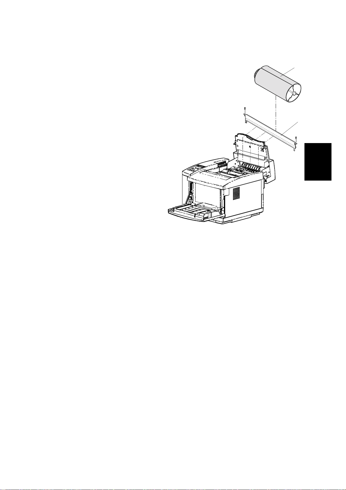
17 January, 2001 DRUM AND ROLLERS
3.6.3 TRANSFER DRUM
Remove the toner cartridges.
Remove the belt cartridge
(photoconductor unit).
Remove the fusing unit.
Remove the cleaner cover.
Remove the drum cleaner.
Open the transfer unit.
☛3.1.5 Top Cover
[A]: Stay A (! x 2)
NOTE: Wrap the transfer drum
surface with paper so that it
will not be scratched. (The
transfer drum as a
maintenance part has a
protective sheet.)
[B]: Transfer Drum
NOTE: Pull the transfer drum from
the top side, and remove the
transfer drum from the shaft support.
[B]
G063R564.WMF
[A]
Replacement
Adjustment
NOTE: Do not touch the transfer drum surface with bare hands, or scratch it.
3-57
Page 95

DRUM AND ROLLERS 17 January, 2001
3.6.4 PAPER FEED ROLLER / SEPARATION PAD
Remove the paper feed cassette.
☛3.6.1 Transfer Unit
• Paper Guide (☛3.5.7 Paper Sensor / OHP Sensor)
• Upper Left Paper Guide (☛3.5.7 Paper Sensor / OHP Sensor)
Disconnect the cables connected to the OHP sensor and paper sensor.
[A]: Paper Feed Roller
NOTE: Sliding the paper feed roller to the right side, remove it from the shaft.
Pull up and remove the separator pad.
[B]: Separation Pad
NOTE: Do not touch the surface of the paper feed roller and separator pad.
[A]
[B]
G063R565.WMF
3-58
Page 96

17 January, 2001 DRUM AND ROLLERS
3.6.5 FRONT COVER UNIT
Open the front cover.
Optical Unit Cover (☛3.3.6 Optical Unit (Including Polygonal Mirror Motor)
☛3.1.13 Front Cover
[A]: Front Inner Cover (! x 4)
[B]: Hinge Support (! x 1," x 1)
[C]: Front Cover Unit (! x 6)
NOTE: When removing the hinge of the front cover unit, watch out for the reboun d
of the spring.
To prevent the above, hold the hinge fixture, then unhook the hook from
the frame.
Adjustment
Replacement
[A]
[B]
[C]
3-59
G063R567.WMF
Page 97

DRUM AND ROLLERS 17 January, 2001
3.6.6 PAPER EXIT ROLLER
Remove the fusing unit.
• Right Side Cover (☛3.1.2 Right Side Cover and Ozone Filter Cover)
☛3.1.3 Left Side Cover
☛3.1.8 LOWER Rear Cover
☛3.1.9 Upper Rear Cover
[A]: Support Pins (one each at left and right side) (! x 2)
[B]: Paper Exit Unit (" x 1)
NOTE: Remove the harness cover and disconnect the harness.
• Paper Exit Cover Ass’y (☛3.1.6 Paper Exit Front Cover / Paper Exit Cover
Ass’y)
[C]: Paper Exit Roller ($ x 2)
[A]
[C]
[B]
[A]
G063R567.WMF
3-60
Page 98

17 January, 2001 DRUM AND ROLLERS
3.6.7 DISCHARGER BRUSH
• Paper Exit Unit (☛3.6.6 Paper Exit Roller)
• Paper Exit Front Cover (☛3.1.6 Paper Exit Front Cover / Paper Exit Cover
Ass’y)
• Paper Exit Cover (☛ 3.1.6 Paper Exit Front Cover / Paper Exit Cover Ass’y)
[A]: Discharger Brush (! x 2)
[A]
Adjustment
Replacement
G063R568.WMF
NOTE: Do not damage the bristles of the discharger brush.
3-61
Page 99

DRUM AND ROLLERS 17 January, 2001
3.6.8 FUSING UNIT CONNECTOR
Remove the fusing unit.
☛3.1.3 Left Side Cover)
• Shield Case A (☛3.2.6 Power Supply Unit)
[A]: Fusing Unit Connector (! x 2, " x 2)
[A]
3-62
G063R570.WMF
Page 100

17 January, 2001 DRUM AND ROLLERS
3.6.9 LOWER WASTE TONER FEEDER
Remove the toner cartridges.
Remove the belt cartridge (photoconductor unit).
• Right Side Cover (☛3.1.2 Right Side Cover and Ozone Filter Cover)
☛3.2.4 IOD2
☛3.1.10 Right Base Cover
[A]: Ozone Fan Duct Assembly (! x 3)
[B]: Lower Waste Toner Feeder (! x 1)
Adjustment
Replacement
[B]
[A]
G063R563.WMF
3-63
 Loading...