Ricoh ap204 Service Manual pom c

POMELO (G033)

SERVICE MANUAL

[Controller]

øIMPORTANT SAFETY NOTICES

PHYSICAL INJURY PREVENTION

1.Before disassembling or assembling parts of the printer and peripherals, make sure that the power cord is unplugged.

2.The wall outlet should be near the printer and easily accessible.

3.Note that some printer components are supplied with electrical voltage even if the main switch is turned off.

4.If an adjustment or operation check must be made requiring the removal or opening of the exterior covers while the main switch is on, keep hands away from electrified or mechanically driven components.

5.The printer drives some of its components when it completes the warm-up period. Keep hands away from mechanical and electrical components when the printer starts operation.

6.The interior and metal parts for the fusing unit become extremely hot while the printer is operating. Do NOT touch these components with bare hands.

HEALTH SAFETY CONDITIONS

1.Never operate the printer without ozone filters installed.

2.Always replace the ozone filters with the specified replacement at the specified maintenance intervals.

3.Toner is non-toxic, but if it gets in your eyes by accident, it may cause temporary eye discomfort. Remove it with eye drops or flush eyes with water. If this is unsuccessful, get medical attention immediately.

SAFETY AND ECOLOGICAL NOTES FOR DISPOSAL

1.Do NOT incinerate toner cartridges or used toner. Toner dust may ignite suddenly when exposed to an open flame.

2.Dispose of used toner and belt cartridge in accordance with local regulations. (These are non-toxic supplies.)

3.Dispose of replaced parts in accordance with local regulations.

Trademarks

Microsoft, Windows 98/95/3.1x, and Windows NT 4.0 are registered trademarks of Microsoft Corporation.

Macintosh and AppleTalk are registered trademarks of Apple Computer, Inc.

NetWare is a registered trademark of Novell, Inc.

Ethernet is a registered trademark of Xerox Corporation.

General Notice:

Other product names used herein are for identification purposes only and may be trademarks of their respective companies. We disclaim any and all rights in those marks.

25 December, 1998

OVERALL MACHINE INFORMATION

1. OVERALL MACHINE INFORMATION

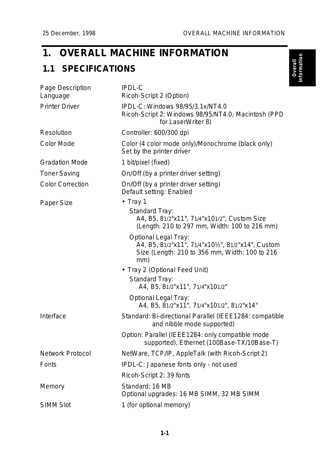
1.1 SPECIFICATIONS

Page Description

IPDL-C

Language

Ricoh-Script 2 (Option)

Printer Driver

IPDL-C: Windows 98/95/3.1x/NT4.0


Ricoh-Script 2: Windows 98/95/NT4.0, Macintosh (PPD


for LaserWriter 8)

Resolution

Controller: 600/300 dpi

Color Mode

Color (4 color mode only)/Monochrome (black only)


Set by the printer driver

Gradation Mode

1 bit/pixel (fixed)

Toner Saving

On/Off (by a printer driver setting)

Color Correction

On/Off (by a printer driver setting)


Default setting: Enabled

Paper Size

Tray 1


Standard Tray:


A4, B5, 81/2"x11", 71/4"x101/2", Custom Size


(Length: 210 to 297 mm, Width: 100 to 216 mm)


Optional Legal Tray:


A4, B5, 81/2"x11", 71/4"x10½", 8 1/2"x14", Custom


Size (Length: 210 to 356 mm, Width: 100 to 216


mm)


Tray 2 (Optional Feed Unit)


Standard Tray:


A4, B5, 81/2"x11", 71/4"x101/2"


Optional Legal Tray:


A4, B5, 81/2"x11", 71/4"x101/2", 81/2"x14"

Interface

Standard: Bi-directional Parallel (IEEE1284: compatible


and nibble mode supported)


Option: Parallel (IEEE1284: only compatible mode


supported), Ethernet (100Base-TX/10Base-T)

Network Protocol

NetWare, TCP/IP, AppleTalk (with Ricoh-Script 2)

Fonts

IPDL-C: Japanese fonts only - not used


Ricoh-Script 2: 39 fonts

Memory

Standard: 16 MB


Optional upgrades: 16 MB SIMM, 32 MB SIMM

SIMM Slot

1 (for optional memory)

Overall Information

1-1

OVERALL MACHINE INFORMATION

25 December, 1998

DIMM Slot

1

(for optional Ricoh-Script 2)


Option Interface

2

(for optional network I/F board and optional parallel


I/F


Options

16 MB Memory


32 MB Memory


Network Interface Board


IEEE1284 Parallel Interface


Ricoh-Script 2 Emulation Module


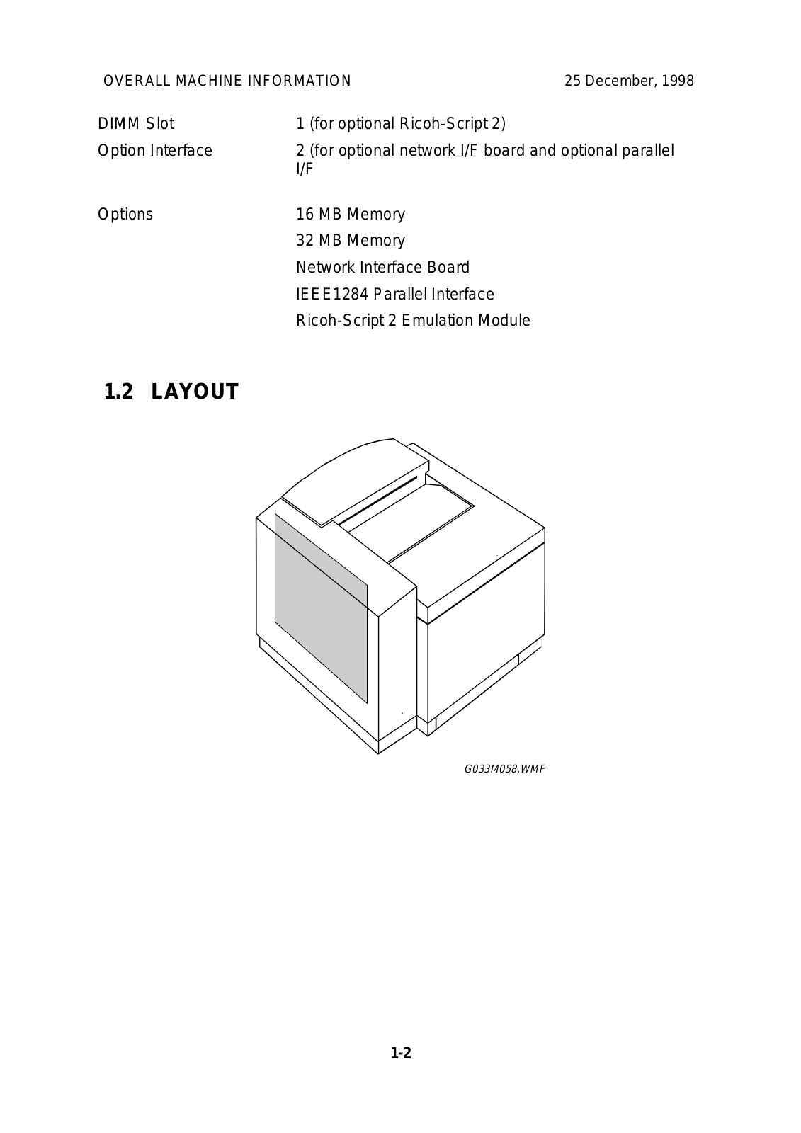
1.2 LAYOUT

G033M058.WMF

1-2

Ricoh ap204 Service Manual pom c

25 December, 1998

DETAILED DESCRIPTIONS

2. DETAILED DESCRIPTIONS

2.1 FUNCTIONAL OVERVIEW

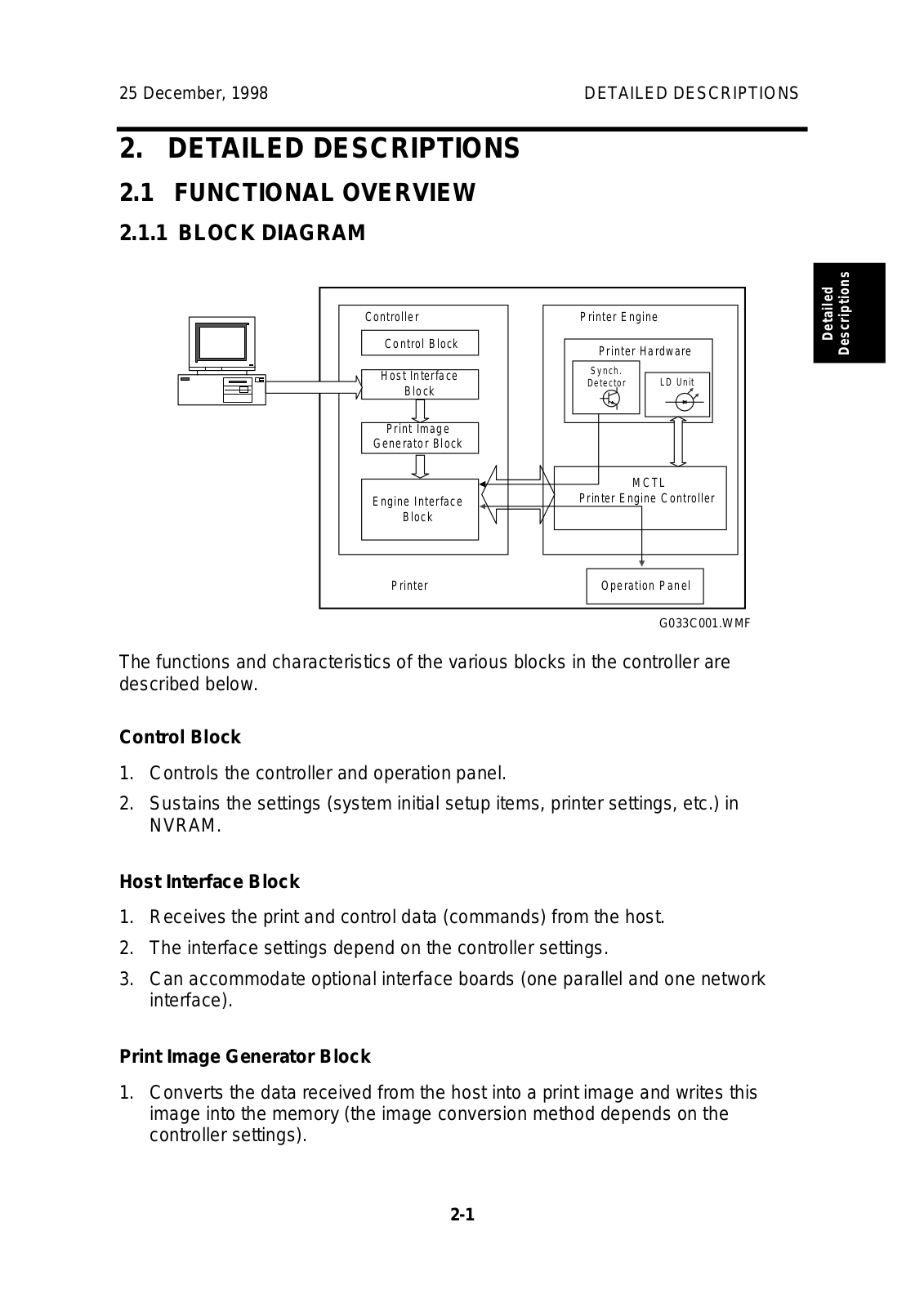
2.1.1 BLOCK DIAGRAM

Controller

Printer Engine

tailed riptions


e c

Control Block

Printer Hardware

D Des


Host Interface

Synch.

LD Unit


Detector


Block


Print Image


Generator Block


MCTL


Engine Interface

Printer Engine Controller


Block


Printer

Operation Panel


G033C001.WMF


The functions and characteristics of the various blocks in the controller are described below.

Control Block

1.Controls the controller and operation panel.

2.Sustains the settings (system initial setup items, printer settings, etc.) in

NVRAM.

Host Interface Block

1.Receives the print and control data (commands) from the host.

2.The interface settings depend on the controller settings.

3.Can accommodate optional interface boards (one parallel and one network interface).

Print Image Generator Block

1.Converts the data received from the host into a print image and writes this image into the memory (the image conversion method depends on the controller settings).

2-1

DETAILED DESCRIPTIONS

25 December, 1998

Engine Interface Block

1.Sends the image data serially on a 1-bit/pixel basis in synchronization with the sync signal and clock from the engine.

2.Receives status data from the engine and passes it to the controller.

3.Sets up the operating mode for the engine.

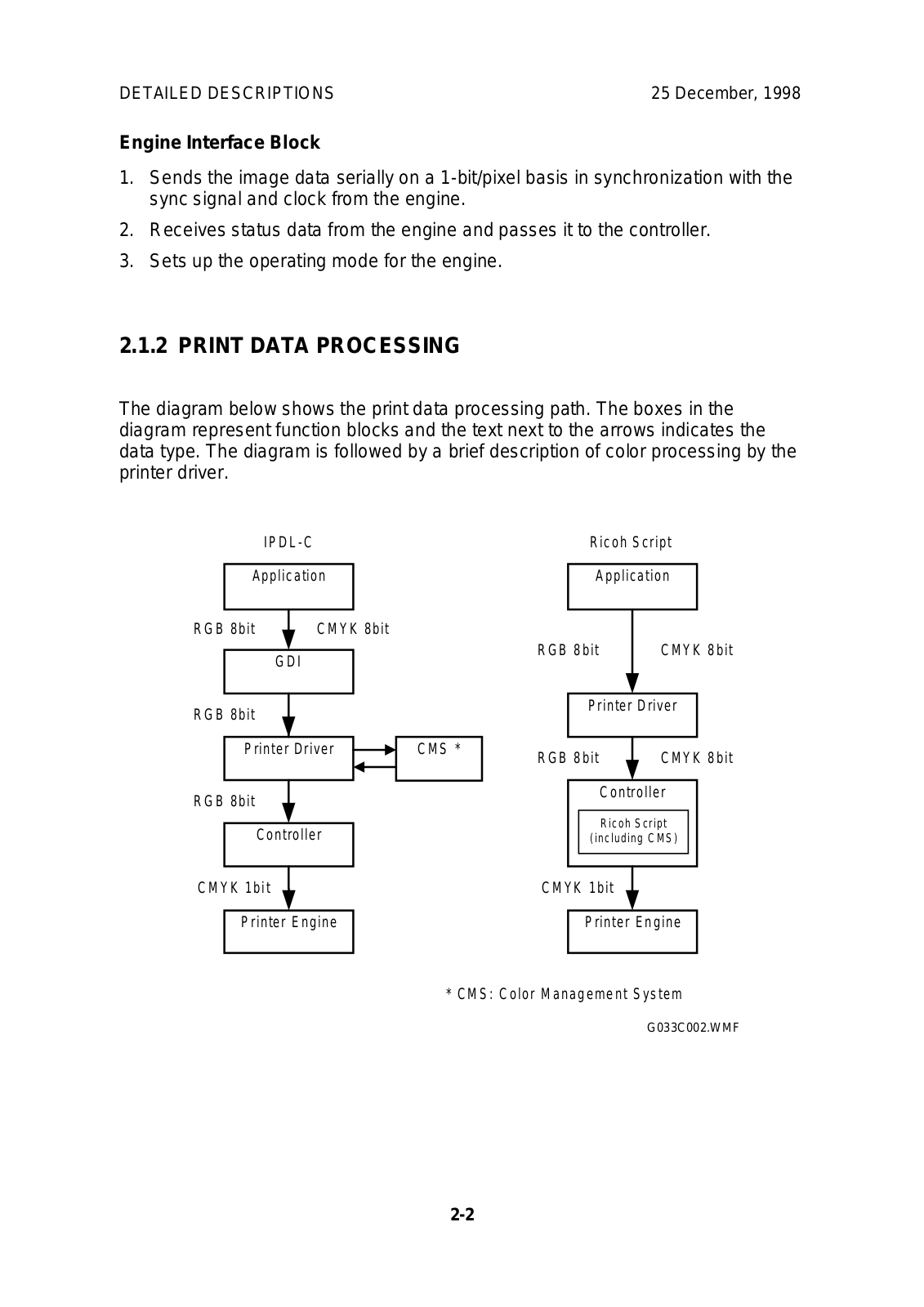
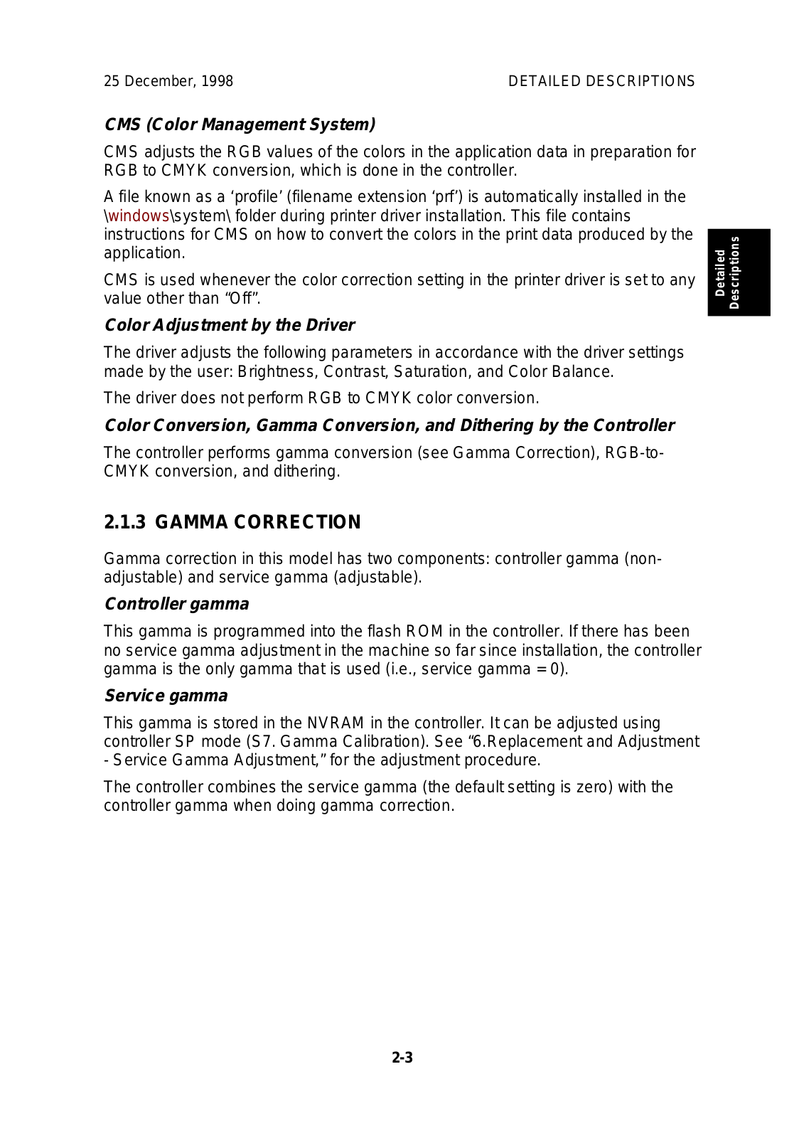
2.1.2 PRINT DATA PROCESSING

The diagram below shows the print data processing path. The boxes in the diagram represent function blocks and the text next to the arrows indicates the data type. The diagram is followed by a brief description of color processing by the printer driver.


IPDL-C


Ricoh Script


Application


Application


RGB 8bit


CMYK 8bit


RGB 8bit


CMYK 8bit


GDI


RGB 8bit


Printer Driver


Printer Driver


CMS *

RGB 8bit


CMYK 8bit


RGB 8bit


Controller


Ricoh Script


Controller


(including CMS)


CMYK 1bit


CMYK 1bit


Printer Engine


Printer Engine


* CMS: Color Management System

G033C002.WMF

2-2

25 December, 1998

DETAILED DESCRIPTIONS

CMS (Color Management System)

CMS adjusts the RGB values of the colors in the application data in preparation for

RGB to CMYK conversion, which is done in the controller.

A file known as a ‘profile’ (filename extension ‘prf’) is automatically installed in the \windows\system\ folder during printer driver installation. This file contains instructions for CMS on how to convert the colors in the print data produced by the application.

CMS is used whenever the color correction setting in the printer driver is set to any value other than “Off”.

Color Adjustment by the Driver

The driver adjusts the following parameters in accordance with the driver settings made by the user: Brightness, Contrast, Saturation, and Color Balance.

The driver does not perform RGB to CMYK color conversion.

Color Conversion, Gamma Conversion, and Dithering by the Controller

The controller performs gamma conversion (see Gamma Correction), RGB-to-

CMYK conversion, and dithering.

Detailed Descriptions

2.1.3 GAMMA CORRECTION

Gamma correction in this model has two components: controller gamma (nonadjustable) and service gamma (adjustable).

Controller gamma

This gamma is programmed into the flash ROM in the controller. If there has been no service gamma adjustment in the machine so far since installation, the controller gamma is the only gamma that is used (i.e., service gamma = 0).

Service gamma

This gamma is stored in the NVRAM in the controller. It can be adjusted using controller SP mode (S7. Gamma Calibration). See “6.Replacement and Adjustment

- Service Gamma Adjustment,” for the adjustment procedure.

The controller combines the service gamma (the default setting is zero) with the controller gamma when doing gamma correction.

2-3

DETAILED DESCRIPTIONS

25 December, 1998

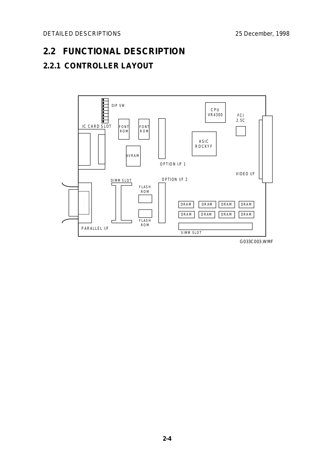
2.2 FUNCTIONAL DESCRIPTION

2.2.1 CONTROLLER LAYOUT


DIP SW


C P U


VR4300


FCI


2.5C


IC CARD SLOT

FONT


FONT


R O M


R O M


ASIC


R O C K Y F


NVRAM


OPTION I/F 1


VIDEO I/F


DIMM SLOT


FLASH

OPTION I/F 2


R O M


DRAM


DRAM


DRAM


DRAM


DRAM


DRAM


DRAM


DRAM


FLASH


PARALLEL I/F


R O M


SIMM SLOT


G033C003.WMF

2-4

25 December, 1998


DETAILED DESCRIPTIONS

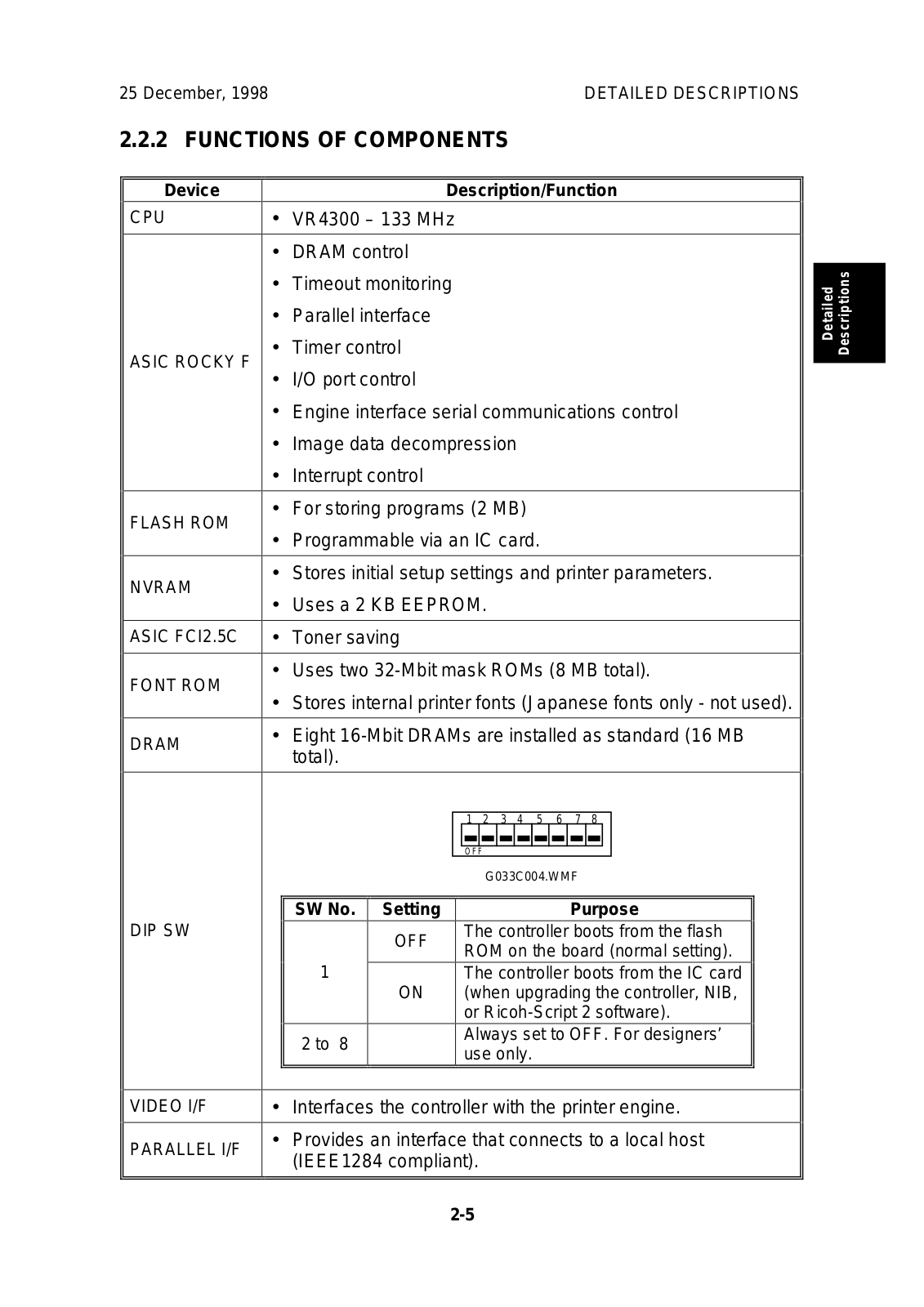
2.2.2 FUNCTIONS OF COMPONENTS


Device


Description/Function

CPU


VR4300 – 133 MHz


DRAM control


Timeout monitoring


Parallel interface


ASIC ROCKY F


Timer control


I/O port control


Engine interface serial communications control


Image data decompression


Interrupt control


FLASH ROM


For storing programs (2 MB)


Programmable via an IC card.


NVRAM


Stores initial setup settings and printer parameters.


Uses a 2 KB EEPROM.


ASIC FCI2.5C


Toner saving


FONT ROM


Uses two 32-Mbit mask ROMs (8 MB total).


Stores internal printer fonts (Japanese fonts only - not used).


DRAM


Eight 16-Mbit DRAMs are installed as standard (16 MB


total).


1


2


3


4


5


6


7

8


O F F


G033C004.WMF


SW No.

Setting


Purpose


DIP SW


OFF


The controller boots from the flash


ROM on the board (normal setting).


1


The controller boots from the IC card


ON


(when upgrading the controller, NIB,


or Ricoh-Script 2 software).


2 to 8


Always set to OFF. For designers’


use only.


VIDEO I/F


Interfaces the controller with the printer engine.


PARALLEL I/F


Provides an interface that connects to a local host


(IEEE1284 compliant).


Detailed Descriptions

2-5

DETAILED DESCRIPTIONS

25 December, 1998


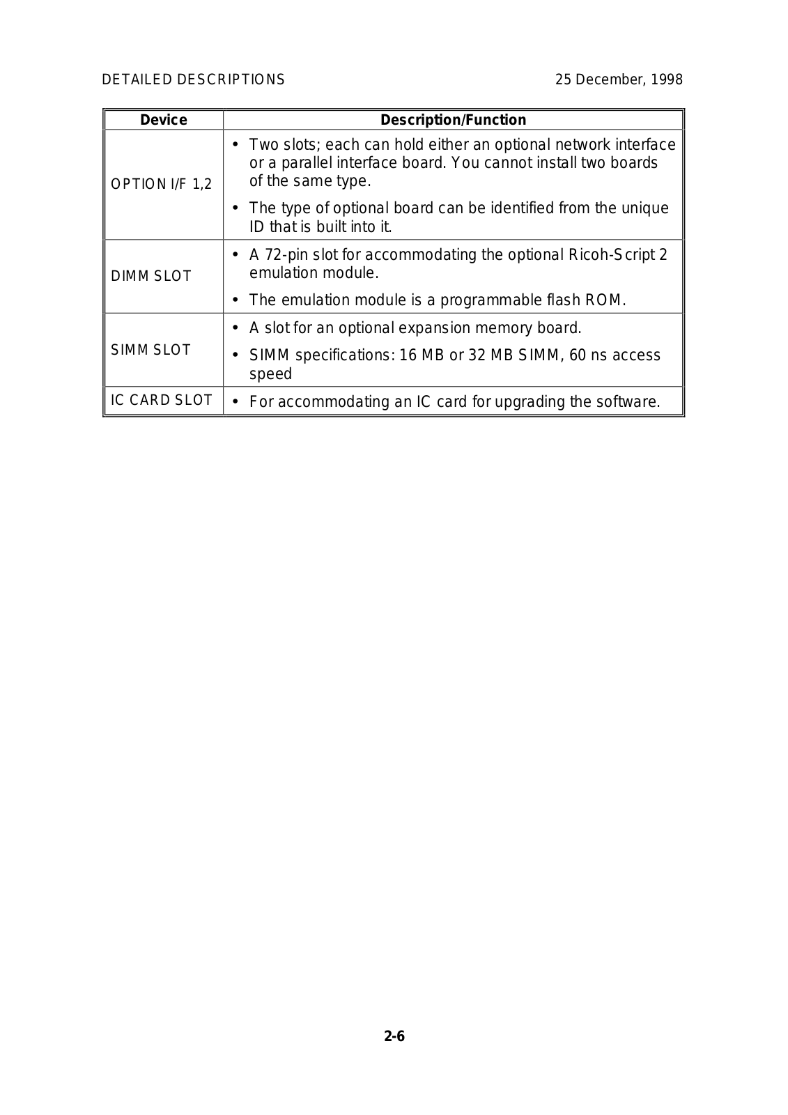
Device

Description/Function


Two slots; each can hold either an optional network interface


or a parallel interface board. You cannot install two boards

OPTION I/F 1,2

of the same type.


The type of optional board can be identified from the unique


ID that is built into it.


A 72-pin slot for accommodating the optional Ricoh-Script 2

DIMM SLOT

emulation module.


The emulation module is a programmable flash ROM.


A slot for an optional expansion memory board.

SIMM SLOT

SIMM specifications: 16 MB or 32 MB SIMM, 60 ns access


speed


IC CARD SLOT

For accommodating an IC card for upgrading the software.


2-6

25 December, 1998

DETAILED DESCRIPTIONS

2.3 POWER-UP SELF-DIAGNOSTICS

2.3.1 OPERATION PANEL DISPLAY DURING POWER-UP SELFDIAGNOSTICS

The controller starts power-up self-diagnostic tests when the printer power is turned on. It shows the test status on the panel as the self-diagnostics proceed.

Immediately after turning the power on

The controller turns on all LEDs and the LCD.

During power-up self-diagnostics

When the controller starts the self-diagnostics, it turns off all LEDs except the Power LED, which it causes to blink. It displays the message “Warming UP” on the first line of the LCD.

If the test terminates normally

If an error is not detected during the self-diagnostic test, the controller turns the blinking Power LED on and turns off all the other LEDs and the LCD. The controller starts the system immediately afterwards.

Detailed Descriptions

If an error is detected

Errors are divided broadly into fatal and non-fatal (user) errors. The controller takes different actions and gives different status information for different types of errors.

See section 7 (Troubleshooting) for tables of the different types of errors.

2-7

DETAILED DESCRIPTIONS

25 December, 1998

Non-fatal error (user error) detected

The controller causes the blinking Power LED to stay on, turns off all of the other

LEDs and the LCD, and restores the standby display state. Since non-fatal errors do not adversely affect any print operation, the controller starts the system immediately after it takes these actions.

The system turns on the Error LED and prints out a list of settings with error descriptions, in monochrome mode (see section 7, Troubleshooting – Controller

User Errors for the error codes).

After printing the above list of settings, the system returns to the normal state and enables all devices except the failed device.

Fatal error detected

Since there is no guarantee that the system can generate a list of settings when the error detected is fatal, the system turns off the Power LED and turns on the Error LED. At the same time, it displays and keeps an error message on the LCD until the power is turned off.

The first line of the LCD contains a 4-digit code that identifies the error. (see section 7, Troubleshooting – Controller Self-diagnostics Errors for a description of the error codes).

2-8

25 December, 1998


DETAILED DESCRIPTIONS

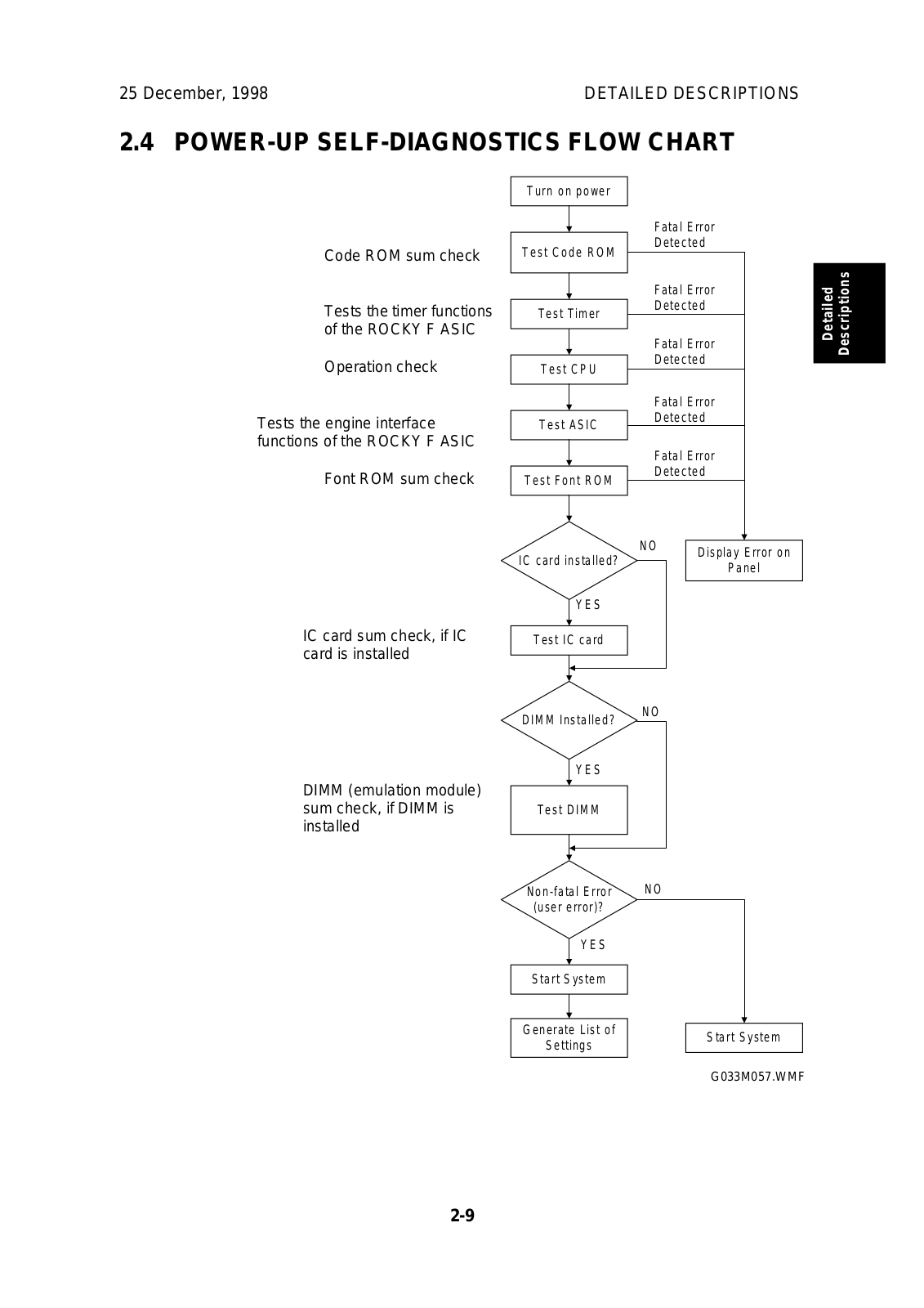
2.4 POWER-UP SELF-DIAGNOSTICS FLOW CHART


Turn on power


Fatal Error


Code ROM sum check

Test Code ROM

Detected


Fatal Error


Tests the timer functions

Test Timer

Detected


of the ROCKY F ASIC


Fatal Error


Operation check


Detected


Test CPU


Fatal Error


Tests the engine interface

Test ASIC

Detected


functions of the ROCKY F ASIC


Fatal Error


Font ROM sum check


Detected


Test Font ROM


Detailed Descriptions

IC card sum check, if IC card is installed

IC card installed?

N O

Display Error on


Panel


YES


Test IC card


DIMM Installed?


N O


YES


DIMM (emulation module)


sum check, if DIMM is

Test DIMM


installed


N O


Non-fatal Error


(user error)?


YES


Start System


Generate List of


Start System


Settings


G033M057.WMF


2-9

25 December, 1998

INSTALLATION

3. INSTALLATION

Refer to the following materials.

For the printer: Quick Installation Guide

For options: Operating Instructions

Installation

3-1

25 December 1998

25 December, 1998

4. SERVICE TABLES

4.1 SP MODES

4.1.1 OVERVIEW

The printer has two types of SP modes:

1.Engine SP modes

2.Controller SP modes

This manual deals with controller SP modes.

4.1.2 ENGINE SP MODE

Refer to the service manual for the engine for how enter engine SP mode and use the engine SP modes.

4.1.3 CONTROLLER SP MODE

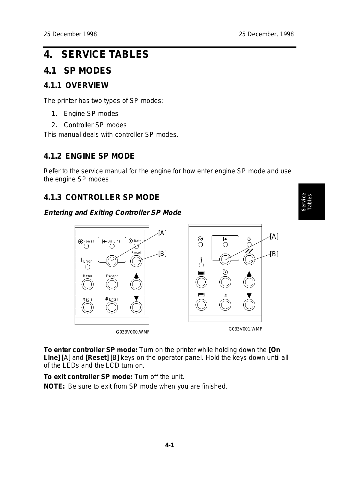
Entering and Exiting Controller SP Mode


[A]

[A]

Power

On Line

Data in


Reset

[B]

[B]


Error

M e n u E s c a p e

Media

#

# Enter

G033V001.WMF

G033V000.WMF

To enter controller SP mode: Turn on the printer while holding down the [On Line] [A] and [Reset] [B] keys on the operator panel. Hold the keys down until all of the LEDs and the LCD turn on.

To exit controller SP mode: Turn off the unit.

NOTE: Be sure to exit from SP mode when you are finished.

Service Tables

4-1

Loading...
+ 36 hidden pages