

Page 1
OPERATING INSTRUCTIONS
Read this manual carefully before you use this product and keep it handy for future
reference.
For safety, please follow the instructions in this manual.
Page 2

RICOH COMPANY, LTD.
15-5, 1 chome, Minami-Aoyama, Minato-ku, Tokyo
Telephone: Tokyo 3479-3111
RICOH CORPORATION
CALLING FOR SERVICE
For service in the United States, plea se call:
1–800–RICOH 38 (1–800–742–6438)
OPERATING INSTRUCTIONS
Overseas Affiliates
U.S.A.
RICOH CORPORATION
5 Dedrick Place
West Caldwell, New Jersey 07006
Phone: +1-973-882-2000
The Netherlands
RICOH EUROPE B.V.
Groenelaan 3, 1186 AA, Amstelveen
Phone: +31-(0)20-5474111
United Kingdom
RICOH UK LTD.
Ricoh House,
1 Plane Tree Crescent, Feltham,
Middlesex, TW13 7HG
Phone: +44-(0)181-261-4000
Germany
RICOH DEUTSCHLAND GmbH
Mergenthalerallee 38-40,
65760 Eschborn
Phone: +49-(0)6196-9060
France
RICOH FRANCE S.A.
383, Avenue du Général de Gaulle
BP 307-92143 Clamart Cedex
Phone: +33-(0)1-40-94-38-38
Spain
RICOH ESPAÑA S.A.
Avda. Litoral Mar, 12-14,
08005 Barcelona
Phone: +34-(0)93-295-7600
Italy
RICOH ITALIA SpA
Via della Metallurgia 12,
37139 Verona
Phone: +39-(0)45-8181500
Hong Kong
RICOH HONG KONG LTD.
23/F., China Overseas Building,
139, Hennessy Road,
Wan Chai, Hong Kong
Phone: +852-2862-2888
Singapore
RICOH ASIA PACIFIC PTE.LTD.
260 Orchard Road,
#15-01/02 The Heeren,
Singapore 238855
Phone: +65-830-5888
Model number: G031–17, G032–17
Printed in Japan
UE USA G031-8607A
Page 3

Introduction
This manual contains detailed instructions on the operation and maintenance of this machine. To get
maximum versatil ity from this ma chine all opera tors sho uld careful ly read an d follow the ins tructi ons in
this manual. Please keep this manual in a handy place near the machine.
Please read the Safety Information before using this machine. It contains important information related
to USER SAFETY and PREVENTING EQUIPMENT PROBLEMS.
Notes:
The model names of the machi nes do not appear in the fol lowing pages. Che ck the model name of your
machine before reading this manual. (For details, see P.2
“Type 1 Printer”
, P.5
“Type 2 Printer”
.)
Descriptions in this manual Model name
Type 1 Printer RICOH LASER AP2000
Type 2 Printer RICOH LASER AP1400
Descriptions without the no te for identifyi ng the type of the prin ter are common for both models . Certain
types might not be available in some countries. For details, please contact your local dealer.
Power Source
RICOH LASER AP2000: 120 V, 60 Hz, 8.0 A or more
RICOH LASER AP1400: 120 V, 60 Hz, 6.0 A or more
Please be sure to connect the power cord to a power source as above.
Operator Safety:
This machine is considered a CDRH clas s I lase r devi ce, safe for office/ EDP use. Th e ma chine con tains 5-milliwat, 760 - 800 nanome ter wavelength, Ga AIAs laser diode. Direc t (or indirect reflected ) eye
contact with the laser b eam m igh t c aus e s eri ous ey e d am age . Sa fety pre ca uti ons an d in terl oc k m ec hanisms have been designed to prevent any possible laser beam exposure to the operator.
Laser Safety:
The Center for Devices and Radiological Health (CDRH) prohibits the repair of laser-based optical unit
in the field. The optical housing unit can only be repaired in a factory or at a location with the requisite
equipment. The laser subsystem is replaceable in the field by a qualified Customer Engineer. The laser
chassis is not repairable in the field. Customer engineers are therefore directed to return all chassis
and laser subsystems to the fac tory or se rvice d epot when replace ment or the op tical subsyste m is required.
Important
Parts of this manual are subject to change without prior notice. In no event will the company be liable
for direct, indirect, special, incidental, or consequential damages as a result of handling or operating
the machine.
Caution:
Use of controls or adjustment or performance of procedures other than those specified in this manual
might result in hazardous radiation exposure.
Do not attempt any mainte nance or troub leshooti ng other th an that ment ioned in this manual. Th is machine contains a laser beam generator and direct exposure to laser beams can cause permanent eye
damage.
Two kinds of size notation are employed in this manual. With this machine refer to the Inch version.
Ricoh shall not be resp onsib le for any damag e or exp ense that m ight res ult fr om the u se of part s other
than genuine Ricoh parts in your Ricoh office product.
For good copy quality, Ricoh recommends that you use genuine Ricoh toner.
Page 4

Note to users in the United States of America
Notice:
This equipment has been tested and found to comply with the limits for a Class B digital device, pursuant to Part 15
of the FCC Rules. These limits are designed to provide reasonable protection against harmful interference in a residential installation. This equipment generates, uses and can radiate radio frequency energy and, if not installed and
used in accordance with the instructions, may cause harmful interference to radio communications.
However, there is no guarantee that interference will not occur in a particular installation. If this equipment does
cause harmful interference to radio or television reception, which can be determined by turning the equipment off
and on, the user is encouraged to try to correct the interference by one more of the following measures:
Reorient or relocate the receiving antenna.
Increase the separation between the equipment and receiver.
Connect the equipment into an outlet on a circu it different from that to w hich the r eceiver i s connected.
Consult the dealer or an experienced radio/TV technician for help.
Warning
Changes or modifications not expressly approved by the party responsible for compliance could void the user's authority to operate the equipment.
Caution (in case of 100BaseTX environment):
Properly shielded and grounded cables (STP) and connectors must be used for connections to host computer (and/
or peripheral) in order to meet FCC emission limits.
Declaration of Conformity
Product Name: Printer
Model Number: G031–17, G032–17
Responsible party: Ricoh Corporation
Address: 5 Dedrick Place, West Caldwell, NJ 07006
Telephone number: 973-882-2000
This device complies with part 15 of FCC Rules.
Operation is subject to the following two conditions:
1. This device may not cause harmful interference, and
2. this device must accept any interference received,
including interference that may cause undesired operation.
Properly shielded cables must be used for connections to host computer (and/or peripheral) in order to
meet FCC emission limits.
Network interface cable with ferrite core must be used for RF interference suppression.
Note to users in Canada
Note:
This Class B digital apparatus complies with Canadian ICES-003.
Remarque concernant les utilisateurs au Canada
Avertissement:
Cet appareil numérique de la classe B est conforme à la norme NMB-003 du Canada.
In accordance with IEC Standard 417, this machine uses the following symbols for the main power switch:
a
means POWER ON.
b
means POWER OFF.
Copyright © 1999 Ricoh Co., Ltd.
Page 5

Introduction
This manual contains detailed instructions on the operation and maintenance of this machine. To get
maximum versatil ity from this ma chine all opera tors sho uld careful ly read an d follow the ins tructi ons in
this manual. Please keep this manual in a handy place near the machine.
Please read the Safety Information before using this machine. It contains important information related
to USER SAFETY and PREVENTING EQUIPMENT PROBLEMS.
Notes:
The model names of the machi nes do not appear in the fol lowing pages. Che ck the model name of your
machine before reading this manual. (For details, see P.2
“Type 1 Printer”
, P.5
“Type 2 Printer”
.)
Descriptions in this manual Model name
Type 1 Printer SAVIN SLP20
Type 2 Printer SAVIN SLP14
Descriptions without the no te for identifyi ng the type of the prin ter are common for both models . Certain
types might not be available in some countries. For details, please contact your local dealer.
Power Source
SAVIN SLP20: 120 V, 60 Hz, 8.0 A or more
SAVIN SLP14: 120 V, 60 Hz, 6.0 A or more
Please be sure to connect the power cord to a power source as above.
Operator Safety:
This machine is considered a CDRH clas s I lase r devi ce, safe for office/ EDP use. Th e ma chine con tains 5-milliwat, 760 - 800 nanome ter wavelength, Ga AIAs laser diode. Direc t (or indirect reflected ) eye
contact with the laser b eam m igh t c aus e s eri ous ey e d am age . Sa fety pre ca uti ons an d in terl oc k m ec hanisms have been designed to prevent any possible laser beam exposure to the operator.
Laser Safety:
The Center for Devices and Radiological Health (CDRH) prohibits the repair of laser-based optical unit
in the field. The optical housing unit can only be repaired in a factory or at a location with the requisite
equipment. The laser subsystem is replaceable in the field by a qualified Customer Engineer. The laser
chassis is not repairable in the field. Customer engineers are therefore directed to return all chassis
and laser subsystems to the fac tory or se rvice d epot when replace ment or the op tical subsyste m is required.
Important
Parts of this manual are subject to change without prior notice. In no event will the company be liable
for direct, indirect, special, incidental, or consequential damages as a result of handling or operating
the machine.
Caution:
Use of controls or adjustment or performance of procedures other than those specified in this manual
might result in hazardous radiation exposure.
Do not attempt any mainte nance or troub leshooti ng other th an that ment ioned in this manual. Th is machine contains a laser beam generator and direct exposure to laser beams can cause permanent eye
damage.
Two kinds of size notation are employed in this manual. With this machine refer to the Inch version.
Savin shall not be responsi ble for any damage or expens e that mi ght resul t from the us e of parts ot her
than genuine Savin parts in your Savin office product.
For good copy quality, Savin recommends that you use genuine Savin toner.
Page 6

Note to users in the United States of America
Notice:
This equipment has been tested and found to comply with the limits for a Class B digital device, pursuant to Part 15
of the FCC Rules. These limits are designed to provide reasonable protection against harmful interference in a residential installation. This equipment generates, uses and can radiate radio frequency energy and, if not installed and
used in accordance with the instructions, may cause harmful interference to radio communications.
However, there is no guarantee that interference will not occur in a particular installation. If this equipment does
cause harmful interference to radio or television reception, which can be determined by turning the equipment off
and on, the user is encouraged to try to correct the interference by one more of the following measures:
Reorient or relocate the receiving antenna.
Increase the separation between the equipment and receiver.
Connect the equipment into an outlet on a circu it different from that to w hich the r eceiver i s connected.
Consult the dealer or an experienced radio/TV technician for help.
Warning
Changes or modifications not expressly approved by the party responsible for compliance could void the user's authority to operate the equipment.
Caution (in case of 100BaseTX environment):
Properly shielded and grounded cables (STP) and connectors must be used for connections to host computer (and/
or peripheral) in order to meet FCC emission limits.
Declaration of Conformity
Product Name: Printer
Model Number: G031–17, G032–17
Responsible party: Ricoh Corporation
Address: 5 Dedrick Place, West Caldwell, NJ 07006
Telephone number: 973-882-2000
This device complies with part 15 of FCC Rules.
Operation is subject to the following two conditions:
1. This device may not cause harmful interference, and
2. this device must accept any interference received,
including interference that may cause undesired operation.
Properly shielded cables must be used for connections to host computer (and/or peripheral) in order to
meet FCC emission limits.
Network interface cable with ferrite core must be used for RF interference suppression.
Note to users in Canada
Note:
This Class B digital apparatus complies with Canadian ICES-003.
Remarque concernant les utilisateurs au Canada
Avertissement:
Cet appareil numérique de la classe B est conforme à la norme NMB-003 du Canada.
In accordance with IEC Standard 417, this machine uses the following symbols for the main power switch:
a
means POWER ON.
b
means POWER OFF.
Page 7

Introduction
This manual contains detailed instructions on the operation and maintenance of this machine. To get
maximum versatil ity from this ma chine all opera tors sho uld careful ly read an d follow the ins tructi ons in
this manual. Please keep this manual in a handy place near the machine.
Please read the Safety Information before using this machine. It contains important information related
to USER SAFETY and PREVENTING EQUIPMENT PROBLEMS.
Notes:
The model names of the machi nes do not appear in the fol lowing pages. Che ck the model name of your
machine before reading this manual. (For details, see P.2
“Type 1 Printer”
, P.5
“Type 2 Printer”
.)
Descriptions in this manual Model name
Type 1 Printer Gestetner P7020
Type 2 Printer Gestetner P7014
Descriptions without the no te for identifyi ng the type of the prin ter are common for both models . Certain
types might not be available in some countries. For details, please contact your local dealer.
Power Source
Gestetner P7020: 120 V, 60 Hz, 8.0 A or more
Gestetner P7014: 120 V, 60 Hz, 6.0 A or more
Please be sure to connect the power cord to a power source as above.
Operator Safety:
This machine is considered a CDRH clas s I lase r devi ce, safe for office/ EDP use. Th e ma chine con tains 5-milliwat, 760 - 800 nanome ter wavelength, Ga AIAs laser diode. Direc t (or indirect reflected ) eye
contact with the laser b eam m igh t c aus e s eri ous ey e d am age . Sa fety pre ca uti ons an d in terl oc k m ec hanisms have been designed to prevent any possible laser beam exposure to the operator.
Laser Safety:
The Center for Devices and Radiological Health (CDRH) prohibits the repair of laser-based optical unit
in the field. The optical housing unit can only be repaired in a factory or at a location with the requisite
equipment. The laser subsystem is replaceable in the field by a qualified Customer Engineer. The laser
chassis is not repairable in the field. Customer engineers are therefore directed to return all chassis
and laser subsystems to the fac tory or se rvice d epot when replace ment or the op tical subsyste m is required.
Important
Parts of this manual are subject to change without prior notice. In no event will the company be liable
for direct, indirect, special, incidental, or consequential damages as a result of handling or operating
the machine.
Caution:
Use of controls or adjustment or performance of procedures other than those specified in this manual
might result in hazardous radiation exposure.
Do not attempt any mainte nance or troub leshooti ng other th an that ment ioned in this manual. Th is machine contains a laser beam generator and direct exposure to laser beams can cause permanent eye
damage.
Two kinds of size notation are employed in this manual. With this machine refer to the Inch version.
Gestetner shall not be responsible for any damage or expense that might result from the use of parts
other than genuine Gestetner parts in your Gestetner office product.
For good copy quality, Gestetner recommends that you use genuine Gestetner toner.
Page 8

Note to users in the United States of America
Notice:
This equipment has been tested and found to comply with the limits for a Class B digital device, pursuant to Part 15
of the FCC Rules. These limits are designed to provide reasonable protection against harmful interference in a residential installation. This equipment generates, uses and can radiate radio frequency energy and, if not installed and
used in accordance with the instructions, may cause harmful interference to radio communications.
However, there is no guarantee that interference will not occur in a particular installation. If this equipment does
cause harmful interference to radio or television reception, which can be determined by turning the equipment off
and on, the user is encouraged to try to correct the interference by one more of the following measures:
Reorient or relocate the receiving antenna.
Increase the separation between the equipment and receiver.
Connect the equipment into an outlet on a circu it different from that to w hich the r eceiver i s connected.
Consult the dealer or an experienced radio/TV technician for help.
Warning
Changes or modifications not expressly approved by the party responsible for compliance could void the user's authority to operate the equipment.
Caution (in case of 100BaseTX environment):
Properly shielded and grounded cables (STP) and connectors must be used for connections to host computer (and/
or peripheral) in order to meet FCC emission limits.
Declaration of Conformity
Product Name: Printer
Model Number: G031–17, G032–17
Responsible party: Ricoh Corporation
Address: 5 Dedrick Place, West Caldwell, NJ 07006
Telephone number: 973-882-2000
This device complies with part 15 of FCC Rules.
Operation is subject to the following two conditions:
1. This device may not cause harmful interference, and
2. this device must accept any interference received,
including interference that may cause undesired operation.
Properly shielded cables must be used for connections to host computer (and/or peripheral) in order to
meet FCC emission limits.
Network interface cable with ferrite core must be used for RF interference suppression.
Note to users in Canada
Note:
This Class B digital apparatus complies with Canadian ICES-003.
Remarque concernant les utilisateurs au Canada
Avertissement:
Cet appareil numérique de la classe B est conforme à la norme NMB-003 du Canada.
In accordance with IEC Standard 417, this machine uses the following symbols for the main power switch:
a
means POWER ON.
b
means POWER OFF.
Page 9

Trademarks
Microsoft®, Windows®, and MS-DOS® are registered trademarks of Microsoft
Corporation in the United States and/or other countries.
®
PostScript
®
PCL
AppleTalk, Apple, Macintosh, TrueType, LaserWriter are registered trademarks
of Apple Computer, Incorporated.
IPS-PRINT™ Printer Language Emulation
DOCUMENT TECHNOLOGIES, INC., All Rights Reserved
Other product names used herein are for identification purposes only and might
be trademarks of their respective companies. We disclaim any and all rights in
those marks.
Notes:
Some illustrations might be slightly different from your machine.
Certain options might not be available in some countries. For details, please con-
tact your local dealer.
is a registered trademark of Adobe Systems. Incorporated.
is a registered trademark of Hewlett-Packard Company.
©
Copyright 1988-1997, XIONICS
Note
The proper names of the Windows operating systems are as follows:
• Microsoft
• Microsoft
• Microsoft
• Microsoft
• Microsoft
®
Windows® 95 operating system
®
Windows® 98 operating system
®
Windows® for Workgroups operating system Version 3.11
®
Windows NT® Server network operating system Version 4.0
®
Windows NT® Workstation operating system Version 4.0
i
Page 10

Safety Information
R
R
When using your equipment, the following safety precautions should always be followed.
Safety During Operation
In this manual, the following important symbols are used:
WARNING:
CAUTION:
Indicates a potentially hazardous situation which, if instructions
are not followed, could result in death or serious injury.
Indicates a potentially hazardous situation which, if instructions are not
followed, may result in minor or moderate injur y or damage to property.
ii
Page 11

R
WARNING:
•
Connect the power cord directly into a wall outlet and never use an extension cord.
•
Disconnect the power plug (by pulling the plug, not the cable) if the
power cable or plug becom es frayed or otherwise damaged.
•
To avoid hazardous electric shock or laser radiation exposure, do not
remove any covers or screws other than those specified in this manual.
•
Turn off the powe r and disconnect the power plug (by pu lling the plug,
not the cable) if any of the following conditions exists:
•
You spill something into the equipment.
•
You suspect that your equipment needs service or repair.
•
Your equipment's cover has been damaged.
•
Do not incinerate spilled tone r or used toner. Toner dust might ign i te
when exposed to an open flame.
•
Disposal can take place at our authorized dealer or at appropriate collection sites.
•
If you dispose of the used toner containers yourself, dispose of them
according to your local regulations.
iii
Page 12

R
CAUTION:
•
Protect the equipment from dampness or wet weather, such as rain, snow,
and so on.
•
Unplug the power cord from the wall outlet before you move the equipment.
While moving the equipment, you should take care that the power cord will
not be damaged under the equipment.
•
When you disconnect the power plug from the wall outlet, always pull the
plug (not the cable).
•
Do not allow paper clips, staples, or other small metallic objects to fall inside
the equipment.
•
Do not eat or swallow toner.
•
Keep toner (used or unused) and toner cartridge out of reach of children.
•
For environmental reasons, do not dispose of the equipment or expended
supply's wastes at a household waste a collection point. Disposal can take
place at our authorized dealer or at an appropriate collection site.
•
Our products are engineered to meet the highest standards of quality and
functionality. When purchasing expendable supplies, we recommend using
only those specified by an authorized dealer.
•
The inside of the machine could be very hot. Do not touch the parts with a
label indicating the “hot surface”. Otherwise, it could cause a personal burn.
iv
Page 13
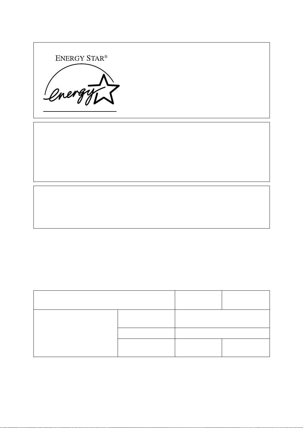
ENERGY STAR Program
As an ENERGY STAR Partner, we have determined that this machine model meets the ENERGY STAR Guidelines for energy efficiency.
The ENERGY STAR Guidelines intend to establish an international energy-saving system for developing and introducing energy-efficient office equipment to deal with environmental issues, such as global warming.
When a product meets the ENERGY STAR Guidelines for energy efficiency, the Partner shall place the ENERGY STAR logo onto the machine model.
This product was designed to reduce the environmental impact associated with office
equipment by means of energy-saving features, such as Low-power mode.
The ENERGY STAR Guidelines intend to establish an international energy-saving system for developing and introducing energy-efficient office equipment to deal with environmental issues, such as global warming.
This product was designed to reduce the environmental impact associated with office
equipment by means of energy-saving features, such as Low-power mode.
❖❖❖❖
Low-power mode (Energy Saver mode)
This printer automatically lowers its power consumption 30 minutes after
the last operation has been completed. To exit Low-power (Energy Saver)
mode, press any key on the operation panel. To change the setting of the Energy Saver mode, see P.125
❖❖❖❖
Specifications
Lower-power mode
(Energy Saver mode)
*1
Please refer to the inside of the front cover of this manual to confirm which printer
(Type 1 Printer or Type 2 Printer) you have.
“Making Printer Settings with the Operation Panel”
Type 1 Printer
*1
Power Consump-
tion
Default Time 30 minutes
Recovery Time 39 seconds or
30 W or less
less
Type 2 Printer
*1
39 seconds or
less
.
v
Page 14

Recycled Paper
-
Please contact your sales or service representative for recommended recycled
paper types that may be used in this machine.
vi
Page 15

Manuals for Your Printer
Manuals for Your Printer
There are two manuals that describe the procedures separately for the installation of your printer and for the operation and maintenance of your printer and
its optional equipment.
To enhance safe and efficient operation of your printer, all users should read and
follow the instructions contained in the following manuals.
❖❖❖❖
Quick Installation Guide
Describes the procedures for installing your printer.
❖❖❖❖
Operating Instructions
Describes the procedures and necessary information on setting up and using
your printer and its optional equipment. (This Manual)
vii
Page 16

How to Read this Manual
R
R
Symbols
In this manual, the following symbols are used:
WARNING:
This symbol indicates a potentially hazardous situation which, if instructions
are not followed, could result in death or serious injury.
CAUTION:
This symbol indicates a potentially hazardous situation which, if instructions
are not followed, may result in minor or moderate injury or damage to property.
* The statements above are notes for your safety.
Important
If this instruction is not followed, paper might be misfed, originals might be
damaged, or data might be lost. Be sure to read this.
Preparation
This symbol indicates the prior knowledge or preparations required before operating.
Note
This symbol indicates precautions for operation, or actions to take after misoperation.
Limitation
This symbol indicates numerical limits, functions that cannot be used together,
or conditions in which a particular function cannot be used.
Reference
This symbol indicates a reference.
[ ]
Keys that appear on the machine's panel display.
Keys and buttons that appear on the computer's display.
{ }
Keys built into the machine's operation panel.
Keys on the computer's keyboard.
viii
Page 17

TABLE OF CONTENTS
1.Getting Acquainted
Features of Your Printer........................................................................... 1
Guide to the Printer................................................................................... 2
Type 1 Printer................................................................................................ 2
Type 2 Printer................................................................................................ 5
Operation Panel............................................................................................ 7
2.Installing Options
Available Options.................................................................................... 12
Type 1 Printer: Installing Options .......................................................... 14
Type 1 Printer: Installing the Paper Feed Unit (DLT) Type 2000................ 14
Type 1 Printer: Installing the Paper Feed Unit (LT) Type 2000................... 15
Type 1 Printer: Installing the Envelope Feeder Type 2000......................... 16
Type 1 Printer: Installing the Network Interface Board Type 2000.............. 16
Type 1 Printer: Installing the Memory Unit (SIMM)..................................... 18
Type 2 Printer: Installing Options .......................................................... 20
Type 2 Printer: Installing the Paper Feed Unit Type 1400 .......................... 20
Type 2 Printer: Installing the Envelope Feeder Type 1400......................... 21
Type 2 Printer: Installing the Network Interface Board Type 2000.............. 22
Type 2 Printer: Installing the Memory Unit (SIMM)..................................... 23
3.Configuring the Printer for the Network with the Operation Panel
Setting Up the IP Parameters................................................................. 26
4.Printer Drivers for Your Printer
Printer Drivers for Your Printer.............................................................. 29
5.Installing the PCL 6/5e Printer Driver
Installing the PCL 6/5e Printer Driver...................................... ..... ..... .... 31
Windows 95/98 - Installing the PCL 6/5e Printer Driver.............................. 31
Windows 3.1x - Installing the PCL 6/5e Printer Driver................................ 32
Windows NT4.0 - Installing the PCL 6/5e Printer Driver ............................. 34
Uninstalling the PCL 6/5e Printer Driver............................................... 36
Windows 95/98 - Uninstalling the PCL 6/5e Printer Driver.......................... 36
Windows 3.1x - Uninstalling the PCL 6/5e Printer Driver............................ 36
Windows NT4.0 - Uninstalling the PCL 6/5e Printer Driver......................... 37
ix
Page 18

6.Installing the PostScript Printer Driver
Installing the PostScript Printer Driver................................................. 39
Windows 95/98 - Installing the PostScript Printer Driver............................. 39
Windows NT4.0 - Installing the PostScript Printer Driver............................ 41
Macintosh - Installing the PPD File............................................................. 44
Uninstalling the PostScript Printer Driver............................................. 47
Windows 95/98 - Uninstalling the PostScript Printer Driver........................ 47
Windows NT4.0 - Uninstalling the PostScript Printer Driver ....................... 47
7.Installing the Font Manager
Installing the Font Manager.................................................................... 49
Windows 95/98 - Installing the Font Manager............................................. 49
Windows 3.1x - Installing the Font Manager............................................... 49
Windows NT4.0 - Installing the Font Manager............................................ 50
Uninstalling the Font Manager............................................................... 51
Windows 95/98 - Uninstalling the Font Manager ........................................ 51
Windows 3.1x - Uninstalling the Font Manager........................................... 51
Windows NT4.0 - Uninstalling the Font Manager ........................................ 51
8.Printing a Document
PCL 6/5e - Accessing the Printer Properties........................................ 53
Windows 95/98 - Accessing the Printer Properties..................................... 53
Windows 3.1x - Accessing the Printer Setting Dialog................................. 54
Windows NT4.0 - Accessing the Printer Properties.................................... 55
PostScript - Setting Up for Printing....................... .... ..... ....................... 57
Windows 95/98 - Accessing the Printer Properties..................................... 57
Windows NT4.0 - Accessing the Printer Properties.................................... 58
Macintosh - Setting Up for Printing ............................................................. 59
Canceling a Print Job.............................................................................. 61
Windows 95/98 - Canceling Print Job........................................................ 61
Windows 3.1x - Canceling a Print Job ........................................................ 61
Windows NT4.0 - Canceling a Print Job ..................................................... 62
9.Paper and Other Media
Paper and Other Media Supported by Your Printer ............................. 65
Paper Types and Sizes............................. .................. ................................ 65
Precautions for Paper ................................................................................. 74
Printable Area ........................ .................................................. ................... 78
Type 1 Printer: Loading Paper and Other Media.................................. 79
Type 1 Printer: Loading Paper in the Standard Paper Tray........................ 79
Type 1 Printer: Loading Paper in the Bypass Tray ..................................... 81
Type 1 Printer: Loading Paper in the Optional Paper Tray ......................... 82
Type 1 Printer: Loading Envelopes.................................................. ........... 84
x
Page 19

Type 2 Printer: Loading Paper and Other Media.................................. 88
Type 2 Printer: Loading Paper in the Standard Paper Tray........................ 88
Type 2 Printer: Loading Paper in the Bypass Tray ..................................... 89
Type 2 Printer: Loading Paper in the Optional Paper Tray ......................... 90
Type 2 Printer: Loading Envelopes.................................................. ........... 92
10.Troubleshooting
Error & Status Messages on the Operation Panel................................ 97
Printer Doesn't Print.............................................................................. 105
Other Printing Problems....................................................................... 107
Removing Misfed Paper........................................................................ 110
When “Remove Misfeed: Front Cover&Tray” Appears ............................. 110
When “Remove Misfeed: Open Front Cover” Appears ............................. 111
Replacing the Toner Cartridge............................................................. 114
Cleaning the Printer .............................................................................. 117
Cleaning the Friction Pad.......................................................................... 117
Cleaning the Paper Feed Roller................................................................ 118
Cleaning the Registration Roller (Type 1 Printer only).............................. 122
11.Making Printer Settings with the Operation Panel
Menu Chart............................................................................................. 125
Accessing the Main Menu..................................................................... 126
Making Printer Settings with the Operation Panel............................. 127
Job Control Menu.................................................................................. 128
Job Control Parameters............................................................................ 128
Host Interface Menu.............................................................................. 136
Host Interface Parameters ....................................................................... 136
Maintenance Menu ........................................................... ..... .... ..... ....... 137
Maintenance Parameters ......................................................................... 137
List Print Menu....................................................................................... 138
List Print Parameters................................................................................. 138
Interpreting the Configuration Page.................................................... 139
12.Appendix
Memory Capacity and Paper Size........................................................ 141
Moving and Transporting the Printer.................................................. 142
Specifications........................................................................................ 143
Mainframe................................................................................................. 143
Options...................................................................................................... 146
Consumables......................................................................................... 149
xi
Page 20

INDEX...................................................................................................... 150
xii
Page 21
1. Getting Acquainted
Features of Your Printer
Your printer is designed especially for office work groups, both for shared usage
within network environment, and for one-to-one usage by being connected directly to your computer.
❖❖❖❖
Time Saving
Superior features save time you spend on your print tasks.
• Fast Print Speed
*1
A4, 81/
" × 11", maximum printing speed from a standard paper tray.
2
• All Front Operation: From the front side, you can replace the toner cartridge, check indicators, and clear a paper misfeed if it occurs.
❖❖❖❖
Compact Body
Its compact body requires minimum space to place it on your desk or desk side.
*1
: 20 ppm (Type 1 printer) and 14 ppm (Type 2 printer)
❖❖❖❖
Network Connectivity
Your printer is network ready with the optional Network Interface Board Type 2000.
❖❖❖❖
Major Specifications
Type 1 Printer
Printing Speed
Maximum Print Quality True 1200 × 1200dpi resolutions (PCL 6, PS)
Emulations
Maximum Input Paper Size Paper Tray and Bypass
Standard Memory Size 8MB 4MB Maximum Memory Size
with Optional Memory
*1
Please refer to the inside of the front cover of this manual to confirm which printer
(Type 1 Printer or Type 2 Printer) you have.
*2
A4L, 81/
*3
A4K, 81/
2
2
" × 11"
" × 11"
L
K
20 pages per minute
PCL 5e, PCL 6, PostScript
Tray:
A3, 11" × 17"
40MB 36MB
*1
*2
®
Level 2
Type 2 Printer
14 pages per minute
Paper Tray: A4K, 8
11" (Letter)
Bypass Tray: A4K, 8
14" (Legal)
K
K
*1
*3
1
/
" ×
2
1
/
" ×
2
1
Page 22
Getting Acquainted
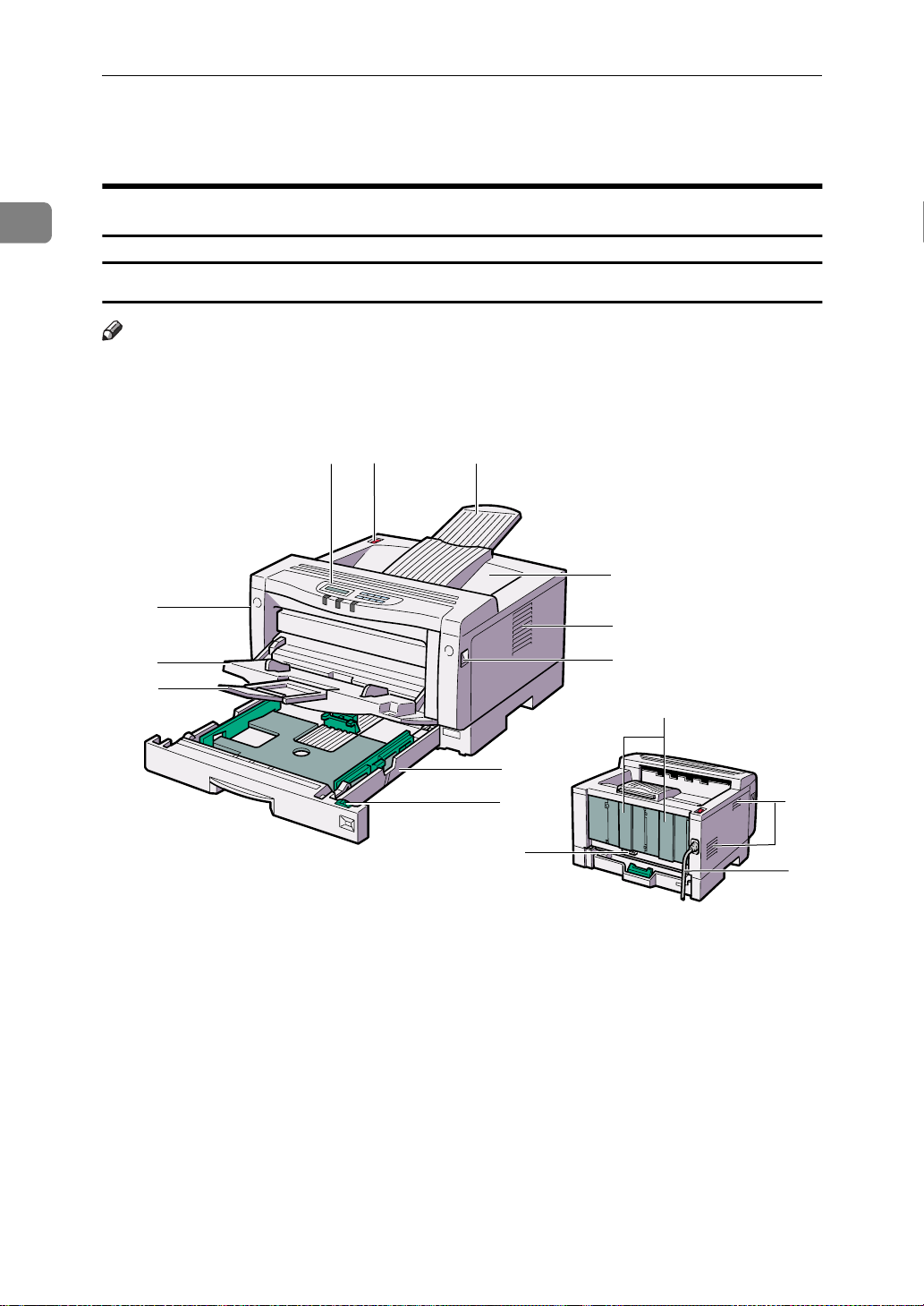
Guide to the Printer
1
Type 1 Printer
Type 1 Printer: Exterior
Note
Please refer to the inside of the front cover of this manual to confirm which
❒
printer (Type 1 Printer or Type 2 Printer) you have.
3
4
8
1
2
5
6
7
8
11
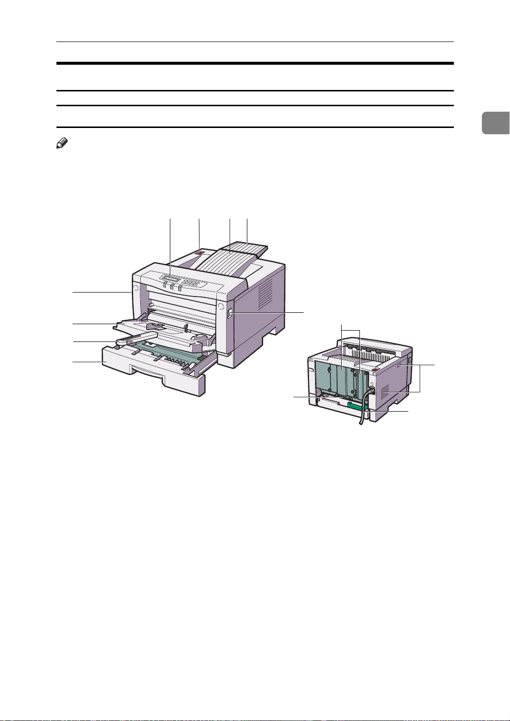
Bypass tray
1.
Use to print onto thick paper, OHP transparencies, adhesive labels, custom size
paper, and envelopes as well as plain paper. When printing on custom paper size,
printer driver's settings are required.
Up to 100 sheets of plain paper (80 g/m
20 lb) can be loaded.
⇒ P.65
by Your Printer”
⇒ P.81
the Bypass Tray”
“Paper and Other Media Supported
“Type 1 Printer: Loading Paper in
2
9
10
12
Bypass Tray Extender
2.
Pull out this extender to load paper into the bypass tray when its length is longer than A4L or 8
Operation Panel
3.
Contains keys for printer operation and a
2
,
panel display that shows the printer status.
Power Switch
4.
Use this switch to turn the printer power on and off.
1
/2” x 11”L.
13
14
TS3H030E
Page 23

Guide to the Printer
Output Tray Extender
5.
Pull out this extender when printing on long paper.
Output Tray
6.
Printed output is stacked here with the print side face down.
Ventilator
7.
These holes help to keep components inside the printer from overheating.
Important
Do not leave the ventilator ob-
❒
structed or blocked. Doing so creates the danger of malfunction due
to overheating.
Front Cover Release Buttons
8.
Use these buttons to open the front cover.
Paper Tray
9.
Loads up to 250 sheets of plain paper (80
2
g/m
, 20 lb) into this tray for printing.
⇒ P.65
by Your Printer”
“Paper and Other Media Supported
Paper Size Dial
10.
Adjust this dial to match the size and feed direction of the paper loaded in the paper tray.
Back Plates
11.
Remove to install some options.
Parallel Interface Connector
12.
Plug into the interface cable that connects the printer to your computer.
Ventilators
13.
These holes help to keep components inside the printer from overheating.
Important
Do not leave the ventilators ob-
❒
structed or blocked. Doing so creates the danger of malfunction due
to overheating.
Power Cord
14.
Plug this cord into a wall outlet.
1
Type 1 Printer: Interior
Note
Please refer to the inside of the front cover of this manual to confirm which
❒
printer (Type 1 Printer or Type 2 Printer) you have.
3
Page 24
1
Getting Acquainted
1
2
1
2
3
4
5
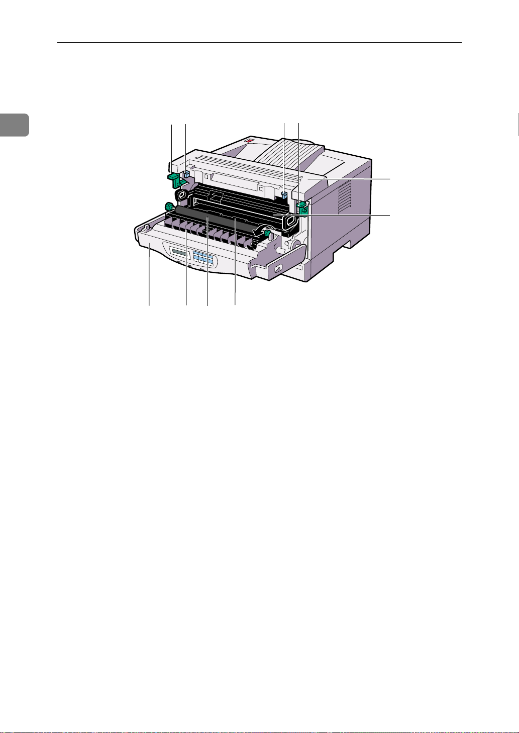
Pressure Release Levers (blue)
1.
Push down these levers when removing misfed paper.
Fusing Unit Lock Levers (brown)
2.
Push down these levers when replacing the fusing unit.
Fusing Unit
3.
Fuses the image onto the paper.
When “Replace Maintenance Kit” ap-
pears on the panel display, replace this
unit.
Toner Cartridge
4.
Includes toner and a photoconductor unit.
Front Cover
5.
Open this cover when accessing the inside of the printer.
6
8
7
Transfer Roller
7.
When “Replace Maintenance Kit” appears on the panel display, replace this
roller.
Registration Roller
8.
Feeds the paper. If it becomes dirty, clean it.
⇒ P.122
(Type 1 Printer only)”
“Cleaning the Registration Roller
Transfer Roller Cover
6.
Open this cover when replacing the transfer roller.
4
Page 25
Type 2 Printer
Guide to the Printer
Type 2 Printer: Exterior
Note
Please refer to the inside of the front cover of this manual to confirm which
❒
printer (Type 1 Printer or Type 2 Printer) you have.
54
6
7
8
8
1
9
2
3
10
12
1
11
Bypass Tray
1.
Use to print onto thick paper, OHP transparencies, adhesive labels, custom size
paper, and envelopes as well as plain paper. When printing on custom paper size,
printer driver's settings are required.
Up to 100 sheets of plain paper (80 g/m
20 lb) can be loaded.
⇒ P.65
by Your Printer”
⇒ P.89
the Bypass Tray”
“Paper and Other Media Supported
“Type 2 Printer: Loading Paper in
Bypass Tray Extender
2.
Pull out this extender to load paper into the bypass tray when its length is longer than B5Kor 5
Paper Tray
3.
Loads up to 250 sheets of plain paper ( 80
2
,
2
g/m
, 20 lb) into this tray for printing.
⇒ P.65
by Your Printer”
Operation Panel
4.
Contains keys for printer operation and a
panel display that shows the printer status.
1
/2” x 1/2”K.
“Paper and Other Media Supported
TS4H031E
5
Page 26
Getting Acquainted
1
Power Switch
5.
Use this switch to turn the printer power on and off.
Output Tray
6.
Printed output is stacked here with the print side face down.
Output Tray Extender
7.
Printed output is stacked here with the print side face down.
Front Cover Release Buttons
8.
Use these buttons to open the front cover.
Back Plates
9.
Remove to install some options.
Parallel Interface Connector
10.
Plug into the interface cable that connects the printer to your computer.
Ventilators
11.
These holes help to keep components inside the printer from overheating.
Important
Do not leave the ventilators ob-
❒
structed or blocked. Doing so creates the danger of malfunction due
to overheating.
Power Cord
12.
Plug this cord into a wall outlet.
Type 2 Printer: Interior
Note
Please refer to the inside of the front cover of this manual to confirm which
❒
printer (Type 1 Printer or Type 2 Printer) you have.
1
2
8
6
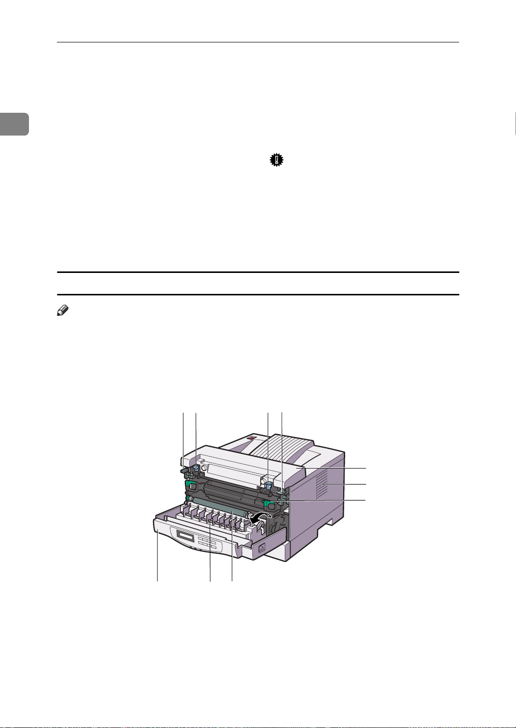
Pressure Release Levers (blue)
1.
Push down these levers when removing misfed paper.
7
1
2
3
4
5
TS4H050J
Fusing Unit Lock Levers (brown)
2.
Push down these levers when replacing the fusing unit.
6
Page 27
Guide to the Printer
Fusing Unit
3.
Fuses the image onto the paper.
When ”Replace Maintenance Kit” ap-
pears on the panel display, replace this
unit.
Ventilator
4.
This hole helps to keep components inside the printer from overheating.
Important
Do not leave the ventilator ob-
❒
structed or blocked. Doing so creates the danger of malfunction due
to overheating of components inside the printer.
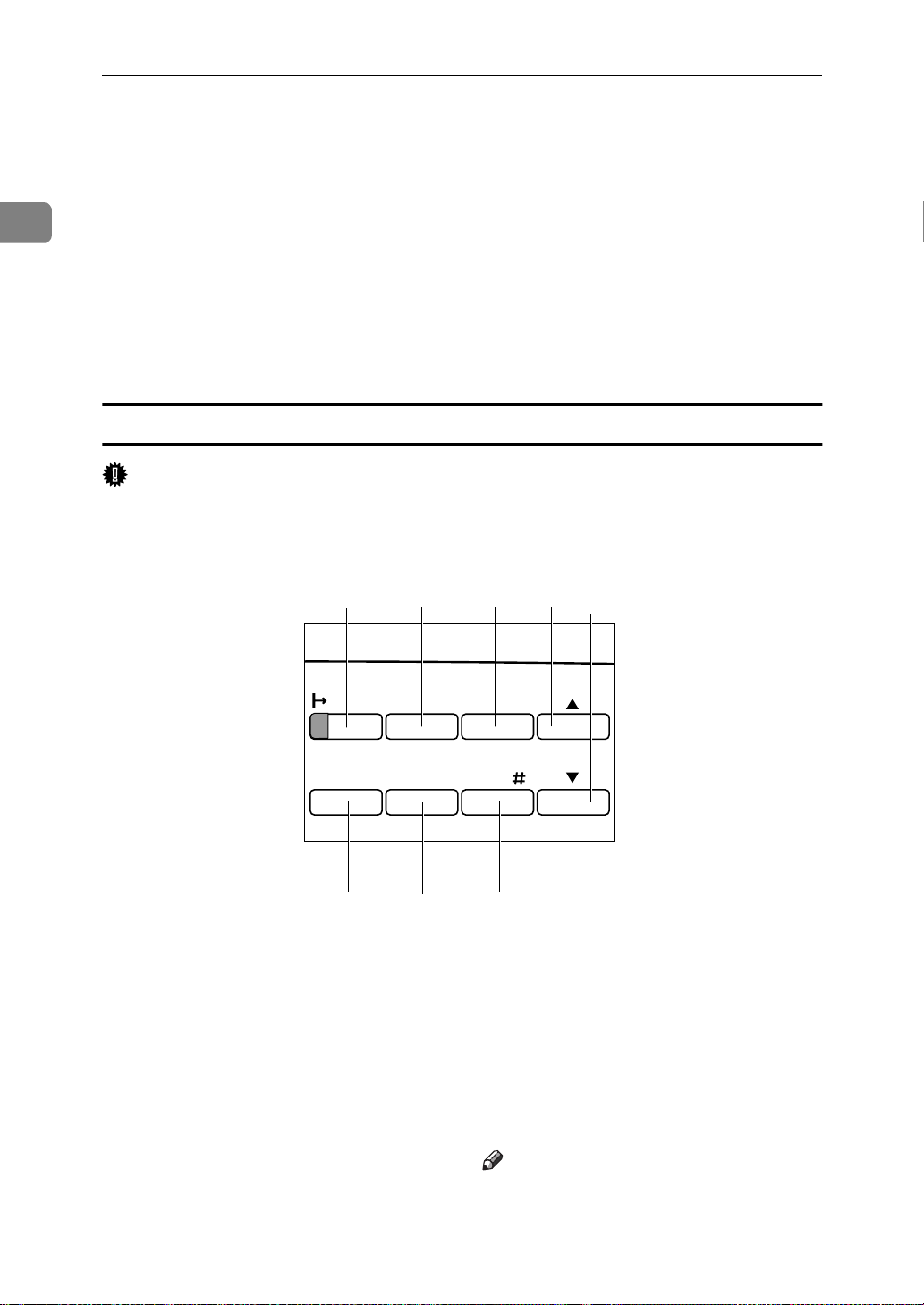
Operation Panel
Toner Cartridge
5.
Includes toner and a photoconductor unit.
Front Cover
6.
Open this cover when accessing the inside of the printer.
Transfer Roller Cover
7.
Open this cover when replacing the transfer roller.
Transfer Roller
8.
When ”Replace Maintenance Kit” appears on the panel display, replace this
roller.
1
1
Power
345
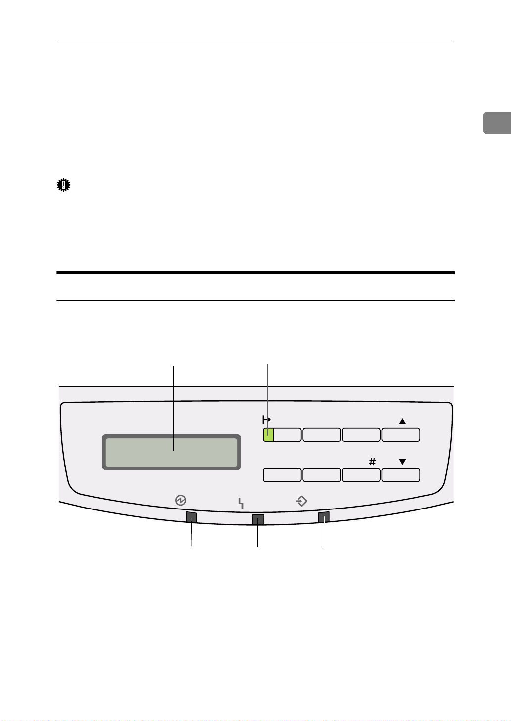
Panel Display
1.
The display shows the current status of the printer and error messages.
⇒ P.97
Operation Panel”
“Error & Status Messages on the
2
On Line
Error
2.
Tells you whether the printer is on-line or off-line.
Stays on while the printer is on-line (a
state in which the printer can receive data
from the computer).
Job Reset
MenuForm Feed
Data In
Escape
Enter
On Line indicator
TS3S010E
7
Page 28
Getting Acquainted
1
Stays off when the printer is off-line (a
state in which printer can not receive data).
Power indicator
3.
Stays on while the printer power is on.
Stays off when the power is turned off or
while the printer is in the Energy Saver
save mode.
Keys
Important
Pressing any operation key while the
❒
may cause data in the printer to be lost.
1
234
Error indicator
4.
Blinks or lights up whenever any printer
error occurs. A message describing the
cause of the error also appears on the
panel display.
⇒ P.97
Operation Panel”
5.
Blinks while the printer is receiving data from a computer.
Stays on if there is data to be printed.
Data In
“Error & Status Messages on the
Data In indicator
indicator is blinking or stays on
On Line
1.
On Line
{
Press this key to switch the printer between on-line and off-line conditions.
2.
Job Reset
{
Pressing this key when the printer is online cancels the ongoing print job. ⇒ P.61
“Canceling a Print Job”
3.
Escape
{
Press this key to return to the previous condition on the panel display.
key
}
key
}
key
}
5
Job Reset
MenuForm Feed
67
Escape
Enter
TS3S020E
4.
{U}{T}
Use these keys to increase or decrease values on the panel display when making settings.
5.
Form Feed
{
Pressing this key during the off-line condition prints out all the data left in the
printer's input buffer.
Note
❒
This is doesn't work in the on-line condition.
keys
}
key
8
Page 29

Guide to the Printer
6.
Menu
{
Press this key to make and check the current printer settings. ⇒ P.125
Printer Settings with the Operation Panel”
7.
Enter
{
Press this key to execute menu items selected on the panel display.
Press this key to clear some errors.⇒ P.97
“Troubleshooting”
key
}
key
}
“Making
1
9
Page 30

1
Getting Acquainted
10
Page 31

2. Installing Options
R
CAUTION:
•
Make sure to turn off the printer and wait for about 30 minutes before installing options. Not waiting for the printer to cool down can result in a burn.
•
When lifting the machine, use the inset grips on both sides of the machine.
Otherwise, the machine might fall and cause personal injury.
•
When you move the machine, unplug the power cord from the wall outlet to
avoid a fire or an electric shock.
❖❖❖❖
Option List
Note
Please refer to the inside of the front cover of this manual to confirm which
❒
printer (Type 1 Printer or Type 2 Printer) you have.
Type 1 Printer Type 2 Printer
Paper Feed Unit (DLT) Type 2000
Paper Feed Unit (LT) Type 2000
Paper Feed Unit Type 1400
Envelope Feeder Type 2000
Envelope Feeder Type 1400
*1
*2
*3
*4
*1
❍
❍
❍
❍
❍
Network Interface Board Type 2000
Memory Unit Type 204 (16MB)
Memory Unit Type 204 (32MB)
: This option can be installed.
❍
*1
Type 1 Printer: You can install any combination of these units. Up to two paper
feed unit can be installed to your printer at a time.
*2
Type 2 Printer: Only one paper feed unit can be installed at a time.
*3
This requires the installation of the Paper Feed Unit Type 2000.
*4
This requires the installation of the Paper Feed Unit Type 1400.
❍❍
❍❍
❍❍
11
Page 32

2
Installing Options
Available Options
The following options can be installed to your printer.
❖❖❖❖
For Type 1 Printer
Note
Please refer to the inside of the front cover of this manual to confirm which
❒
printer (Type 1 Printer or Type 2 Printer) you have.
4 5,6
1
2
Paper Feed Unit (LT) Type 2000
1.
Paper Feed Unit (DLT) Type 2000
2.
Envelope Feeder Type 2000
3.
Network Interface Board Type
4.
2000
Memory Unit Type 204 (16MB)
5.
(SIMM)
Memory Unit Type 204 (32MB)
6.
(SIMM)
Note
It is impossible to install more than two paper feed units to your printer at a
❒
time.
3
TS3P100E
12
Page 33

Available Options
Any combination of Paper Feed Unit (LT) Type 2000 and Paper Feed Unit
❒
(DLT) Type 2000 is available.
The envelope feeder is a tray that slides into the optional paper feed unit.
❒
Without the optional paper feed unit, the envelope feeder cannot be used.
The Type 1 Printer can have two optional paper feed units installed at a time.
❒
However the envelope feeder should be used in the top-most optional paper
feed unit (tray 2). It cannot be used in the bottom-most paper feed unit (tray
3).
❖❖❖❖
For Type 2 Printer
Note
Please refer to the inside of the front cover of this manual to confirm which
❒
printer (Type 1 Printer or Type 2 Printer) you have.
2
1
Paper Feed Unit Type 1400
1.
Envelope Feeder Type 1400
2.
Network Interface Board Type
3.
2000
3
4,5
2
TS4P100E
Memory Unit Type 204 (16MB)
4.
(SIMM)
Memory Unit Type 204 (32MB)
5.
(SIMM)
Note
It is impossible to install more than one paper feed unit to your printer at a
❒
time.
13
Page 34

Installing Options
R
Type 1 Printer: Installing Options
used to hold the tray in place. Re-
Type 1 Printer: Installing the
move both pieces of tape.
2
Paper Feed Unit (DLT) Type
2000
Note
Please refer to the inside of the
❒
front cover of this manual to confirm which printer (Type 1 Printer
or Type 2 Printer) you have.
Important
Do not slide more than one paper
❒
tray out at a time. Having more
than one paper tray filled with paper in a fully extended position
could cause the machine to tilt forward.
To make the printer recognize the
❒
installed option, you should set up
the option with the printer driver.
Check the contents of the box for
A
the following items.
Attach the tray cover to the top of
D
the paper tray as shown in the illustration.
There are four pins on the top of
E
the paper feed unit that point
straight up. On the bottom of the
printer are four holes. Align the
holes over the pins and lower the
printer gently onto the paper feed
unit.
TS3P070E
14
• Paper feed unit (including a
paper tray)
• Tray cover
• Installation Guide
Be sure to check the following
B
points:
• The printer's power switch is
turned off.
• The power cord is unplugged
from the wall outlet.
• The interface cable is unplugged from the printer.
• The bypass tray and front cover are closed.
At the front of the paper feed unit,
C
tape on the left and right sides is
CAUTION:
•
When lifting the printer, use the
inset grips on both sides.
TS3P061E
Page 35

Type 1 Printer: Installing Options
R
• The interface cable is unplugged from the printer.
• The bypass tray and front cover are closed.
At the front of the paper feed unit,
C
tape on the left and right sides is
used to hold the tray in place. Remove both pieces of tape.
2
TS3K010E
Type 1 Printer: Installing the Paper Feed Unit (LT) Type 2000
Note
Please refer to the inside of the
❒
front cover of this manual to confirm which printer (Type 1 Printer
or Type 2 Printer) you have.
Important
Do not slide more than one paper
❒
tray out at a time. Having more
than one paper tray filled with paper in a fully extended position
could cause the machine to tilt forward.
To make the printer recognize the
❒
installed option, you should set up
the option with the printer driver.
Check the content of the box for
A
the following items.
There are four pins on the top of
D
the paper feed unit that point
straight up. On the bottom of the
printer are four holes. Align the
holes over the pins and lower the
printer gently onto the paper feed
unit.
CAUTION:
•
When lifting the printer, use the
inset grips on both sides.
TS3P062E
• Paper feed unit (including a
paper tray)
• Installation Guide
Be sure to check the following
B
points:
• The printer's power switch is
turned off.
• The power cord is unplugged
from the wall outlet.
TS3K010E
15
Page 36

2
Installing Options
Type 1 Printer: Installing the Envelope Feeder Type 2000
Note
Please refer to the inside of the
❒
front cover of this manual to confirm which printer (Type 1 Printer
or Type 2 Printer) you have.
until it stops. After that, lift it
slightly, then pull it out.
Important
This unit is a tray that slides into
❒
the optional paper feed unit. Without the optional paper feed unit,
this envelope feeder cannot be
used.
The Type 1 Printer can have two
❒
optional paper feed units installed
at a time. However, the envelope
feeder should be used in the topmost optional paper feed unit (tray
2). It can not be used in the bottom-
most paper feed unit (tray 3).
Do not slide more than one paper
❒
tray out at a time. Having more
than one paper tray filled with paper in a fully extended position
could cause the machine to tilt toward.
Check the content in the box for
A
the following items.
Important
The envelope feeder should be
❒
used in the top-most optional
paper feed unit (tray 2).
Note
Keep the paper tray with paper
❒
in a cool and dry place.
While lifting the front side of the
C
envelope feeder, place the feeder
into the printer. Then slide it into
the printer until it stops.
TS3Y150E
• Envelope feeder
• Installation Guide
Pull out the 2nd paper tray (tray 2)
B
of the optional paper feed unit
Type 1 Printer: Installing the Network Interface Board Type 2000
16
Note
When loading envelopes, see
❒
“Type 1 Printer: Loading En-
P.84
velopes”
Note
Please refer to the inside of the
❒
front cover of this manual to confirm which printer (Type 1 Printer
or Type 2 Printer) you have.
.
TS3Y290E
Page 37

Type 1 Printer: Installing Options
Use the shielded twisted-pair
❒
(STP) network interface cable.
The network interface board can
❒
be attached to either the left or the
right side of the back of your printer. This procedure is for attaching
to the left side.
You cannot install two network in-
❒
terface boards at a time.
Check the contents of the box for
A
the following items.
• Network interface board
• CD-ROM
• Ferrite Core
• Installation Guide
• Quick Configuration Guide
• Additional Documentation
Be sure to check the following
B
points:
• The printer's power switch is
turned off.
• The power cord is unplugged
from the wall outlet.
used to be. Make sure that the
board is aligned so that the jack is
facing out and is on the bottom.
Press the board firmly against the
printer. The interface connectors
on the printer and the board
should align and offer a slight resistance before popping into
place.
Note
Use a coin to reattach the
❒
screws.
Loop the network interface cable
E
and attach the ferrite core as
shown in the illustration.
2
TS3P090E
Remove the back plate.
C
Note
A coin can be used to remove
❒
the screws.
Align the screw holes of the net-
D
work interface board over the
screw holes where the back plate
TS3P080E
1
Note
The network interface cable
❒
loop should be about 15 cm (6")
(A) from the end of the cable
(on the end closest to the printer). The ferrite core at the end of
the cable should be a ring type
ferrite core.
TS3P110E
17
Page 38

Installing Options
2
Attach the network interface ca-
F
ble to the jack on the board as
shown in the illustration.
Connect the other end of the net-
G
work interface cable to the network.
Plug the printer's power cord
H
back into the wall outlet and turn
on the printer's power switch.
The configuration page of the network interface board will be printed automatically. Check the
configuration of the network interface board with it.
TS3C041E
Important
The memory unit can be damaged
❒
by small amount of static electricity. Before touching it, touch something metal to remove static
electricity from you.
To make the printer recognize the
❒
installed option, you should set up
the option with the printer driver.
This printer has one slot for a
❒
SIMM, and you can install one
SIMM at a time.
Be sure to check the following
A
points:
• The printer's power switch is
turned off.
• The power cord is unplugged
from the wall outlet.
Remove the back plate.
B
Important
After installing the network in-
❒
terface board properly, set up
the printer's network environment using the operation panel.
See P.25
for the Network with the Operation
Panel”
“Configuring the Printer
.
Type 1 Printer: Installing the Memory Unit (SIMM)
Note
Please refer to the inside of the
❒
front cover of this manual to confirm which printer (Type 1 Printer
or Type 2 Printer) you have.
18
Note
A coin can be used to remove
❒
the screws.
Make sure that the notch of the
C
memory unit should be upward
as shown in the illustration. Tilt
the memory unit to the left so that
it is in 45 degrees from perpendicular to the slot, and slide it into
the slot (A). Tilt the memory unit
so that it is perpendicular to the
TS3P030E
Page 39

slot (B). It should make an audible click as it pops into place.
1
Type 1 Printer: Installing Options
2
Attach the back plate to its origi-
D
nal position.
Note
A coin can be used to attach the
❒
screws.
2
TS3S040E
TS3P050E
Turn on the printer's power
E
switch.
Print a configuration test sheet to
F
confirm that the memory unit is
properly installed.
Reference
⇒
P.125
with the Operation Panel”
“Making Printer Settings
19
Page 40

2
R
Installing Options
Type 2 Printer: Installing Options
There are four pins on the top of
Type 2 Printer: Installing the Paper Feed Unit Type 1400
Note
Please refer to the inside of the
❒
front cover of this manual to confirm which printer (Type 1 Printer
or Type 2 Printer) you have.
Important
Do not slide more than one paper
❒
tray out at a time. Having more
than one paper tray filled with paper in a fully extended position
could cause the machine to tilt forward.
D
the paper feed unit that point
straight up. On the bottom of the
printer are four holes. Align the
holes over the pins and lower the
printer gently onto the paper feed
unit.
To make the printer recognize the
❒
installed option, you should set up
the option with the printer driver.
Check the contents of the box for
A
the following items.
• Paper feed unit (including a
paper tray)
• Installation Guide
Be sure to check the following
B
points:
• The printer's power switch is
turned off.
• The power cord is unplugged
from the wall outlet.
• The interface cable is unplugged from the printer.
• The bypass tray and front cover are closed.
At the front of the paper feed unit,
C
tape on the left and right sides is
used to hold the tray in place. Remove both pieces of tape.
CAUTION:
•
When lifting the printer, use the
inset grips on both sides.
Pull the paper tray out until it
E
stops. After then, lift it slightly,
TS4P121E
TS4K010E
20
Page 41

Type 2 Printer: Installing Options
then pull it out of the printer.
Place it on a flat surface.
Note
Do not touch the three white
❒
pins on the right front side of
the paper feed unit.
Remove the white protective
F
sheet from inside of the paper
tray.
TS4Y091E
er. Then slide it into the printer
until it stops.
Type 2 Printer: Ins talling the Envelope Feeder Type 1400
Note
Please refer to the inside of the
❒
front cover of this manual to confirm which printer (Type 1 Printer
or Type 2 Printer) you have.
Important
This unit is a tray that slides into
❒
the optional paper feed unit. Without the optional paper feed unit,
this envelope feeder cannot be
used.
Do not slide more than one paper
❒
tray out at a time. Having more
than one paper tray filled with paper in a fully extended position
could cause the machine to tilt toward.
2
Remove the red protective sheet
G
taped on the guide.
While lifting the front side of the
H
paper tray, place it into the print-
TS4Y111E
TS4Y301E
Check the content of the box for
A
the following items.
• Envelope feeder
• Installation Guide
Pull out the paper tray of the op-
B
tional paper feed unit until it
stops. After that, lift it sightly,
then pull it out.
TS4Y150E
21
Page 42

Installing Options
2
Note
Keep the paper tray with paper
❒
in a cool and dry place.
While lifting the front side of the
C
envelope feeder, place the feeder
into the printer. Then slide it into
the printer until it stops.
Note
When loading envelopes, see
❒
“Type 2 Printer: Loading En-
P.92
velopes”
.
TS4Y290E
• Additional Documentation
Be sure to check the following
B
points:
• The printer's power switch is
turned off.
• The power cord is unplugged
from the wall outlet.
Remove the back plate.
C
Note
A coin can be used to remove
❒
the screws.
TS4P030E
Type 2 Printer: Installing the Network Interface Board Type 2000
Note
Please refer to the inside of the
❒
front cover of this manual to confirm which printer (Type 1 Printer
or Type 2 Printer) you have.
Use the shielded twisted-pair
❒
(STP) network interface cable.
Check the contents in the box for
A
the following items.
• Network interface board
• CD-ROM
• Ferrite Core
• Installation Guide
• Quick Configuration Guide
Align the screw holes of the net-
D
work interface board over the
screw holes where the back plate
used to be. Make sure that the
board is aligned so that the jack is
facing out and is on the bottom.
Press the board firmly against the
printer. The interface connectors
on the printer and the board
should align and offer a slight re-
22
Page 43

Type 2 Printer: Installing Options
sistance before popping into
place.
Note
Use a coin to reattach the screws
❒
Loop the network interface cable
E
and attach the ferrite core as
shown in the illustration.
TS4P090E
Attach the network interface ca-
F
ble to the jack on the board as
shown in the illustration.
Connect the other end of the net-
G
work interface cable to the network.
Plug the printer's power cord
H
back into the wall outlet and turn
on the printer's power switch.
The configuration page of the network interface board will be printed automatically. Check the
configuration of the network interface board with it.
2
TS4C041E
1
Note
The network interface cable
❒
loop should be about 15 cm (6")
(A) from the end of the cable
(on the end closest the printer).
The ferrite core at the end of the
cable should be a ring type ferrite core.
TS3P110E
Important
After installing the network in-
❒
terface board properly, set up
the printer's network environment using the operation panel.
See P.25
for the Network with the Operation
Panel”
“Configuring the Printer
.
Type 2 Printer: Ins talling the Memory Unit (SIMM)
Note
Please refer to the inside of the
❒
front cover of this manual to confirm which printer (Type 1 Printer
or Type 2 Printer) you have.
23
Page 44

Installing Options
2
Important
The memory unit can be damaged
❒
by small amount of static electricity. Before touching it, touch something metal to remove static
electricity from you.
To make the printer recognize the
❒
installed option, you should set up
the option with the printer driver.
This printer has one slot for a
❒
SIMM, and you can install one
SIMM at a time.
Be sure to check the following
A
points:
• The printer's power switch is
turned off.
• The power cord is unplugged
from the wall outlet.
Remove the back plate.
B
the slot (B). It should make an audible click as it pops into place.
Attach the back plate to its origi-
D
nal position.
1
2
TS4P040E
Note
A coin can be used to remove
❒
the screws.
Make sure that the notch of the
C
memory unit should be downward as shown in the illustration.
Tilt the memory unit to the right
so that it is in 45 degrees from perpendicular to the slot, and slide it
into the slot (A). Tilt the memory
unit so that it is perpendicular to
TS4P060E
Note
A coin can be used to attach the
❒
screws.
Turn on the printer's power
E
switch.
Print a configuration test sheet to
F
confirm that the memory unit is
properly installed.
Reference
⇒
P.125
with the Operation Panel”
“Making Printer Settings
TS4P050E
24
Page 45

3. Configuring the Printer for
the Network with the
Operation Panel
25
Page 46

Configuring the Printer for the Network with the Operation Panel
Setting Up the IP Parameters
3
After installing the optional network
interface board, configure it for the
network using the printer's operation
panel.
Reference
⇒
P.16
the Network Interface Board Type
2000”
⇒
P.22
the Network Interface Board Type
2000”
Press
A
The following message appears on the panel display.
“Type 1 Printer: Installing
“Type 2 Printer: Installing
.
Menu
{
}
Main Menu: j
Job Control l
Press
B
message appears.
{T}{U}
until the following
The following message appears on the panel display.
Network Setup: j
1.IP Address l
Press
F
The current IP address appears on
the panel display. A pointer (k)
blinks on the value to be specified.
Enter
{
.
}
IP Address: jld#
000.000.000.000
Specify the first (leftmost) 3 digits
G
of the IP address using
Use
{T}
to increase a value, and
{U}
to decrease.
{U} {T}
IP Address: jld#
100.000.000.000
.
26
Main Menu: j
Host Interfacel
Press
C
The following message appears on the panel display.
{
Enter
.
}
Host Interface:j
1.Printer Lang.l
Press
D
message appears.
{T}{U}
until the following
Host Interface:j
1.Network Setupl
E
Press
{
Enter
.
}
Press
H
A pointer (k) moves to the second 3 digits.
❒
❒
Repeat steps G and H to specify
I
the rest of the digits of the IP address.
Check if the pointer (k) is at the
J
rightmost digit, press
Enter
{
Note
Before pressing
return the pointer (k) to the previous (left) 3 digits by pressing
Escape
{
If you press
pointer (k) is on the leftmost 3
digits, the specified IP address
is canceled and you can return
to the previous panel display.
.
}
Enter
{
.
}
Escape
{
, you can
}
when the
}
Enter
{
}
to
Page 47

Setting Up the IP Parameters
register the IP address you specified.
The following message appears on the panel display.
Network Setup: j
1.IP Address l
Press
K
message appears.
{T}{U}
until the following
Network Setup: j
2.Subnet Mask l
Press
L
The current subnet mask appears on the panel display.
{
Enter
.
}
Subnet Mask:jld#
255.000.000.000
Gateway jld#
000.000.000.000
Specify the gateway address us-
Q
ing the same procedure for specifying the IP address.
Check if the pointer (k) is at the
R
rightmost digit, press
register the gateway address you
specified.
The following message appears on the panel display.
Enter
{
Network Setup: j
3 .Gateway l
Press
S
The panel display returns to the ready condition as follows:
On Line
{
.
}
}
to
3
Specify the subnet mask using
M
the same procedure for specifying
the IP address.
Check if the pointer (k) is at the
N
rightmost digit, press
register the subnet mask you
specified.
The following message appears on the panel display.
Enter
{
Network Setup: j
2.Subnet Mask l
Press
O
message appears.
{T}{U}
until the following
Network Setup: j
3.Gateway l
Press
P
The current gateway address appears on the panel display.
{
Enter
.
}
}
to
Ready
Turn the printer's power switch
T
off and on.
27
Page 48

3
Configuring the Printer for the Network with the Operation Panel
28
Page 49

4. Printer Drivers for Your
Printer
Printer Drivers for Your Printer
Printing requires installation of a printer driver for your operating system. The
following drivers are provided with this printer.
Emulation PCL 5e PCL 6 PostScript
Level2
Operating system
Windows 95
Windows 98
Windows 3.1x
Windows NT4.0
Macintosh
*4
*5
*6
*7
√√
√√
√√
√√
√
√
√
*1 *2 *3
√
*1
*1
*1
*1
PPD (PostScript Printer Description) files are included in the CD-ROM.
*2
The optional network interface board is required.
*3
You can use the LaserWriter printer driver. Use the appropriate printer driver that
comes with the Macintosh operating system you are using. See the documentation
that comes with your Macintosh for details on the LaserWriter functions.
*4
Microsoft® Windows® 95 operating system
*5
Microsoft® Windows® 98 operating system
*6
Microsoft® Windows® for Workgroups operating system Version 3.11
*7
Microsoft® Windows NT® Server network operating system Version 4.0, Microsoft
Windows NT® Workstation operating system Version 4.0
❖❖❖❖
PCL printer drivers
Printer drivers allow the computer to communicate with the printer via a
printer language. Two kinds of PCL printer drivers, PCL 6 and PCL 5e, are
provided with this printer. We recommend the PCL 6 as your first choice.
However, some of your applications might require the installation of the PCL
5e printer driver. In this case, you can install PCL 5e in addition to the PCL 6.
⇒
⇒
⇒
❖❖❖❖
PostScript Printer Description (PPD) files for Windows
“Windows 95/98 - Installing the PCL 6/5e Printer Driver”
P.31
“Windows 3.1x - Installing the PCL 6/5e Printer Driver”
P.32
“Windows NT4.0 - Installing the PCL 6/5e Printer Driver”
P.34
The printer specific functions can be used by installing the PPD file specific for your printer.
⇒
⇒
“Windows 95/98 - Installing the PostScript Printer Driver”
P.39
“Windows NT4.0 - Installing the PostScript Printer Driver”
P.41
®
29
Page 50

4
Printer Drivers for Your Printer
❖❖❖❖
PostScript Printer Description (PPD) files for Macintosh
PPD files, in combination with the LaserWriter driver, allow the computer to
communicate with the printer. The printer specific functions can be used by
installing a PPD file. You can use the LaserWriter printer driver that comes
with your Macintosh. Use the appropriate printer driver that comes with the
Macintosh operating system you are using. See the documentation that comes
with your Macintosh for details on the LaserWriter functions.
⇒
“Macintosh - Installing the PPD File”
P.44
30
Page 51

5. Installing the PCL 6/5e
Printer Driver
Installing the PCL 6/5e Printer Driver
This section provides basic procedures for installing the printer driver. The actual procedure differs somewhat depending on your operating system. Follow
the right one of the procedures below.
We recommend the PCL 6 as your first choice. However, some of your application software might require the installation of the PCL 5e printer driver. In this
case, you can install the PCL 5e in addition to the PCL 6.
Important
When you set the print resolution to 300dpi, you should install the PCL 5e
❒
driver.
When you set the printer resolution to 1200dpi, you should install the PCL 6
❒
driver.
When updating the printer driver by installing the latest version, you should
❒
uninstall the former version, if any.
Windows 95/98 - Installing t he PCL 6/5e Printer Driver
Installing the printer driver
Follow these steps to install the PCL 6/5e printer driver on your Windows 95/ 98 system:
Insert the CD-ROM that comes with your printer in the CD-ROM drive.
A
Close all applications that are currently running.
B
Click
C
Click
D
In the
E
Select the CD-ROM Drive.
F
Open the folder called
G
Open the folder called
H
Open the folder of the appropriate language for your operating system.
I
on the task bar.
Start
[
]
.
Run
[
]
window, click
Run
[
]
Browse
[
PCL5E
[
WIN31_95
[
]
or
[
.
]
.
]
PCL6
.
]
Open the folder called
J
DISK1
[
.
]
31
Page 52

Installing the PCL 6/5e Printer Driver
5
Select the file titled
K
Click
L
Click
M
Follow the instructions on the screen.
N
If you are asked if you want to restart Windows, select
O
asked, restart Windows after completing the installation.
Click
P
The
Select the icon of the printer you installed by clicking it.
Q
On the
R
On the
S
❒
[
[
[
Printers
[
Important
If your printer is equipped with certain options (ex. paper feed unit or
memory unit), you should set up the options with the printer driver.
.
Open
]
.
OK
]
on the task bar, point to
Start
]
window appears.
]
menu, click
File
[
]
General
[
]
SETUP.EXE
[
tab, click
Properties
[
[
.
]
Settings
[
.
]
Print Test Page
, and then click
]
.
]
. If you are not
Yes
[
]
Printers
[
.
]
Setting up options
Click
A
Printers
The
[
Select the icon of the printer you want to use by clicking it.
B
On the
C
The Printer Properties appears.
Click the
D
Set up any options you have installed on your printer.
E
Click
F
on the task bar, point to
Start
[
]
window appears.
]
menu, click
File
[
]
Accessories
[
.
OK
[
]
tab.
]
Properties
[
Settings
[
.
]
, and then click
]
Printers
[
.
]
Windows 3.1x - Installing the PCL 6/5e Print er Driver
Installing the printer driver
Follow these steps to install the PCL 6/5e printer driver on your Windows 3.1x system:
32
Page 53

Installing the PCL 6/5e Printer Driver
Insert the CD-ROM that comes with your printer in the CD-ROM drive.
A
Close all applications that are currently running.
B
From the
C
In the
D
Select the CD-ROM Drive in the
E
Open the folder called
F
Open the folder called
G
Open the folder of the appropriate language for your operating system.
H
Open the folder called
I
Select the file titled
J
Click
K
Click
L
Follow the instructions on the screen.
M
If you are asked if you want to restart Windows, select
N
asked, restart Windows after completing the installation.
Important
If your printer is equipped with certain options (ex. paper feed unit or
❒
memory unit), you should set up the options with the printer driver.
Program Manager
[
window, click
Run
[
]
.
OK
[
]
.
OK
[
]
[
, select
]
Browse…
[
PCL5E
[
WIN31_95
[
DISK1
[
SETUP.EXE
]
]
or
.
]
[
[
[
.
]
.
Run
]
.
]
Drives
PCL6
from the
list.
]
.
]
File
[
menu.
]
Yes
[
. If you are not
]
5
Setting up options
From the
A
ble-clicking it.
Double-click the
B
In the
C
use so its name is highlighted.
Click
D
Click the
E
Set up any options you have installed on your printer.
F
Click
G
Installed Printers
[
Setup
[
OK
[
]
group of the
Main
[
]
Printers
[
.
]
Accessories
[
.
Program Manager
[
icon.
]
list box, click the name of the printer you want to
]
tab.
]
, open
]
Control Panel
[
by dou-
]
33
Page 54

Installing the PCL 6/5e Printer Driver
5
H
Click
[
Close
]
to close the
Printers
[
dialog.
]
Windows NT4.0 - Installing the PCL 6/5e Printer Driver
Installing the printer driver
Limitation
Installing the printer driver requires full control access rights. To install the
❒
printer driver, log on as an Administrator or a Power Users group member.
Insert the CD-ROM that comes with your printer in the CD-ROM drive.
A
Close all applications that are currently running.
B
Click
C
Click
D
In the
E
Select the CD-ROM Drive.
F
on the task bar.
Start
[
]
.
Run
[
]
window, click
Run
[
]
Browse
[
.
]
Open the folder called
G
Open the folder called
H
Open the folder of the appropriate language for your operating system.
I
Open the folder called
J
Select the file titled
K
Click
L
Click
M
Follow the instructions on the screen.
N
If you are asked if you want to restart Windows, select
O
asked, restart Windows after completing the installation.
Click
P
The
Select the icon of the printer you installed by clicking it.
Q
On the
R
[
[
[
Printers
[
.
Open
]
.
OK
]
on the task bar, point to
Start
]
window appears.
]
menu, click
File
[
]
PCL5E
[
NT4
[
DISK1
[
SETUP.EXE
[
or
]
.
]
.
]
]
Properties
[
.
PCL6
[
.
]
[
.
]
Settings
Yes
[
, and then click
]
. If you are not
]
Printers
[
.
]
34
On the
S
General
[
tab, click
]
Print Test Page
[
.
]
Page 55

Installing the PCL 6/5e Printer Driver
Important
If your printer is equipped with certain options (ex. paper feed unit or
❒
memory unit), you should set up the options with the printer driver.
Setting up options
Click
A
Printers
The
[
Select the icon of the printer you want to use by clicking it.
B
On the
C
The Printer Properties appears.
Click the
D
Set up any options you have installed on your printer.
E
Click
F
on the task bar, point to
Start
[
]
windows appears.
]
menu, click
File
[
]
Accessories
[
.
OK
[
]
tab.
]
Properties
[
Settings
[
.
]
, and then click
]
Properties
[
.
]
5
35
Page 56

Installing the PCL 6/5e Printer Driver
Uninstalling the PCL 6/5e Printer Driver
This section provides basic procedures for uninstalling the printer driver. The
actual procedure differs somewhat depending on your operating system.
Follow one of the procedures below.
Windows 95/98 - Uninstalling the PCL 6/5e Printer Driver
Follow these steps to uninstall the printer driver:
Insert the CD-ROM that comes with your printer in the CD-ROM drive.
A
Close all applications that are currently running.
B
5
Click
C
Click
D
In the
E
Select the CD-ROM Drive.
F
Open the folder called
G
Open the folder called
H
Open the folder of the appropriate language for your operating system.
I
Open the folder called
J
Select the file titled
K
Click
L
Click
M
Follow the instructions on the screen.
N
If you are asked if you want to restart Windows, select
O
asked, restart Windows after completing the uninstallation.
on the task bar.
Start
[
]
.
Run
[
]
window, click
Run
[
]
.
Open
[
]
.
OK
[
]
Browse
[
PCL5E
[
WIN31_95
[
DISK1
[
UNSETUP.EXE
[
]
]
or
.
[
.
]
]
.
]
PCL6
.
.
]
. If you are not
Yes
[
]
Windows 3.1x - Uninstalling the PCL 6/5e Printer Driver
Follow these steps to uninstall the PCL 6/5e printer driver on your Windows
3.1x system:
Insert the CD-ROM that comes with your printer in the CD-ROM drive.
A
Close all applications that are currently running.
B
36
Page 57

Uninstalling the PCL 6/5e Printer Driver
From the
C
In the
D
Select the CD-ROM Drive in the
E
Open the folder called
F
Open the folder called
G
Open the folder of the appropriate language for your operating system.
H
Open the folder called
I
Select the file titled
J
Click
K
Click
L
Follow the instructions on the screen.
M
If you are asked if you want to restart Windows, select
N
asked, restart Windows after completing the uninstallation.
Program Manager
[
window, click
Run
[
]
.
OK
[
]
.
OK
[
]
[
, select
]
Browse…
[
PCL5E
[
WIN31_95
[
DISK1
[
UNSETUP.EXE
]
]
or
]
.
Run
[
]
Drives
[
PCL6
[
.
.
]
from the
]
.
list.
]
.
]
File
[
menu.
]
Yes
[
. If you are not
]
5
Windows NT4.0 - Uninstalling the PCL 6/5e Printer Driver
Limitation
Uninstalling the printer driver requires full control access rights. To uninstall
❒
the printer driver, log on as an Administrator or a Power Users group member.
Insert the CD-ROM that comes with your printer in the CD-ROM drive.
A
Close all applications that are currently running.
B
Click
C
Click
D
In the
E
Select the CD-ROM Drive.
F
Open the folder called
G
Open the folder called
H
Open the folder of the appropriate language for your operating system.
I
on the task bar.
Start
[
]
.
Run
[
]
window, click
Run
[
]
PCL5E
[
NT4
[
Browse
[
or
]
.
]
.
]
PCL6
[
.
]
Open the folder called
J
DISK1
[
.
]
37
Page 58

Installing the PCL 6/5e Printer Driver
5
Select the file titled
K
Click
L
Click
M
Follow the instructions on the screen.
N
If you are asked if you want to restart Windows, select
O
asked, restart Windows after completing the installation.
[
[
Open
.
OK
]
.
]
UNSETUP.EXE
[
.
]
. If you are not
Yes
[
]
38
Page 59

6. Installing the PostScript
Printer Driver
Installing the PostScript Printer Driver
Printing requires installation of a printer driver for your operating system.
This section provides basic procedures for installing the printer driver. The ac-
tual procedure differs somewhat depending on your operating system. Follow
the right one of the procedures below.
Important
When updating the printer driver by installing the latest version, you should
❒
uninstall that of former version, if any.
Windows 95/98 - Installing t he PostScript Printer Driver
Installing the printer driver
Important
The Windows 95 or Windows 98 operating system CD-ROM or diskettes are
❒
required for installation.
Be sure to install the PPD file for Windows 95/98. Do not install the PPD file
❒
for Windows NT4.0 accidently.
Close all applications that are currently running.
A
Click
B
Printers
The
[
Double-click
C
Add Printer Wizard
The
[
Click
D
Check
E
A dialog for selecting the printer manufacturer and model name appears.
Click
F
A dialog for installing the driver from a disk opens.
Insert the CD-ROM that comes with your printer into your computer's CD-
G
ROM drive.
on the task bar, point to
Start
[
]
window opens.
]
Add Printers
[
starts up.
]
.
Next
[
]
Local Printer
[
Have Disk
[
, and click
]
.
]
icon.
]
Next
[
Settings
[
.
]
, and then click
]
Printers
[
.
]
H
Click
Browse
[
.
]
39
Page 60

Installing the PostScript Printer Driver
6
Use the
I
In the
J
folder of the appropriate language for your operating system. Finally, click
OK
[
Click
K
Select the name of the printer whose driver you want to install by clicking
L
it, and then click
In the
M
Next
[
Change the name of the printer, if you want, and then click
N
Specify whether or not you want to print a test page, and then click
O
If you are asked to insert the Windows 95/98 system disk, insert it into your
P
computer, and then click
If you are asked to specify the location of the required file for Windows 95/
Q
98, do the following:
• Select the folder
• Move to the folder where Windows is installed. Then, select the appropriate folder. The location of the appropriate folder may differ depending on
the version of your operating system. The following are examples:
[
[
Drives:
[
Folders:
[
.
]
OK
[
]
Available ports:
[
.
]
\WINDOWS\SYSTEM\OPTION\CABS
\WINDOWS\OPTION\CABS
list box to select the CD-ROM drive.
]
box, double-click
]
.
Next
[
box, select
]
WIN95
[
.
]
.
OK
[
]
WIN98
or
]
[
]
and
[PS]
Printer Port
[
in the system disk.
]
]
WIN95
[
]
. Then double-click the
]
by clicking it, and then click
.
Next
[
]
[
Finish
.
]
If you are asked if you want to restart Windows, select
R
asked, restart Windows after completing the installation.
Important
If your printer is equipped with certain options (ex. paper feed unit or
❒
memory unit), you should set up the options with the printer driver.
Using the printer driver with the Adobe PageMaker for Windows 95/
-
98
If you use the printer under Windows 95/98 with the Adobe PageMaker, you
need to copy the PPD file to the PageMaker directory.
The PPD file is the file with extension ".ppd" under on the directory
\PS\WIN95\ENGLISH\, on the CD-ROM that comes with your printer. The
last directory, "ENGLISH" may be substituted by appropriate language name.
Copy this file to the PageMaker's directory.
40
. If you are not
Yes
[
]
Page 61

Installing the PostScript Printer Driver
For PageMaker 6 default installation, the directory is "C:\PM6\USENGLISH\PPD4", and for PageMaker 6.5 default installation, the directory is
"C:\PM65\RSRC\USENGLISH\PPD4". The "USENGLISH" may be different,
depending on your language selection.
Setting up options
Click
A
Printers
The
[
Select the icon of the printer you want to use by clicking it.
B
On the
C
The Printer Properties appears.
Click the
D
In the
E
printer.
The current setting is displayed in the
Use the
F
selected option.
Click
G
Repeat steps E– G for all options.
H
After making all settings for options, click
I
on the task bar, point to
Start
[
]
window appears.
]
menu, click
File
[
]
Device Options
[
Installable Options
[
Change settings for:
[
Apply
[
to apply the settings you made.
]
]
]
Settings
[
Properties
[
tab.
group, select the option you have installed to your
list box to select the appropriate setting for the
]
.
]
Change setting for:
[
, and then click
]
.
OK
[
]
list box.
]
Printers
[
.
]
6
Windows NT4.0 - Installing the PostScript Printer Driver
Installing the printer driver
Limitation
Installing the printer driver requires full control access rights. To install the
❒
printer driver, log on as an Administrator or a Power Users group member.
Important
The CD-ROM containing the Windows NT Server network operating system
❒
Version 4.0, or the Windows NT Workstation operating system is required for
installing the printer driver.
41
Page 62

Installing the PostScript Printer Driver
We recommend that you upgrade your Windows NT4.0 operating system to
❒
the latest version before installing the printer driver. Contact your Windows
retailer for details about the latest version available.
Be sure to install the PPD file for Windows NT4.0. Do not accidently install
❒
the PPD file for Windows 95/98.
Close all applications that are currently running.
A
6
Click
B
Printers
The
[
Double-click the
C
Add Printer Wizard
The
[
After confirming the
D
A dialog for selecting the printer port appears.
Check the check box of the port you want to use, and then click
E
A dialog for selecting the printer manufacturer and model appears.
Click
F
A dialog for installing the driver from a disk appears.
Insert the CD-ROM that comes with your printer into your computer's CD-
G
ROM drive.
Change the drive name in the list box to the name of the CD-ROM drive,
H
and then click
In the
I
folder of the appropriate language for your operating system. Finally, click
Open
[
]
on the task bar, point to
Start
[
]
window opens.
]
Add Printers
[
starts up.
]
My Computer
[
Have Disk
[
Folders:
[
.
.
]
Browse
[
box, double-click
]
.
]
Settings
[
icon.
]
option is selected, click
]
and
[PS]
, and then click
]
WINNT4
[
Printers
[
.
Next
[
]
Next
[
. Then double-click the
]
.
]
]
42
Click
J
A printer model selection dialog appears.
Select the name of the printer whose driver you want to install by clicking
K
it, and then click
A dialog for changing the printer name appears.
Change the name of the printer, if you want, and then click
L
Click
M
In the next dialog asking if you want to print a test page, select
N
then click
The installer copies the printer driver files from the CD-ROM to your computer's hard disk.
OK
[
Next
[
.
]
.
]
Finish
[
[
.
]
Next
.
]
.
Next
[
]
No
[
and
]
Page 63

Installing the PostScript Printer Driver
Note
Perform a test print after completing installation and restarting Windows.
❒
If you are asked to insert the Windows NT4.0 system disk, insert it into
O
your computer, and then click
If you are asked to specify the drive of the system disk, specify the drive of
P
the Windows NT4.0 system disk.
If you are asked to specify the location of the required file, select the appro-
Q
priate folder. The location of the appropriate folder may differ depending
on the version of your operating system. The following is an example:
OK
[
.
]
• folder named
After installation is completed, the
the newly installed printer.
If you are asked if you want to restart Windows, select
R
asked, restart Windows after completing the installation.
Important
If your printer is equipped with certain options (ex. paper feed unit or
❒
memory unit), you should set up the options with the printer driver.
Using the printer driver with the Adobe PageMaker for Windows
-
NT4.0
If you use the printer under Windows NT4.0 with the Adobe PageMaker, you
need to copy the PPD file to the PageMaker directory.
The PPD file is the file with extension ".ppd" under on the directory
\PS\WINNT4\ENGLISH\, on the CD-ROM that comes with your printer. The
last directory, "ENGLISH" may be substituted by appropriate language name.
Copy this file to the PageMaker's directory.
For PageMaker 6 default installation, the directory is "C:\PM6\RSRC\PPD4",
and for PageMaker 6.5 default installation, the directory is
"C:\PM65\RSRC\USENGLISH\PPD4". The "USENGLISH" may be different,
depending on your language selection.
i386
of the Windows NT4.0 system disk.
[
]
Printers
[
window appears with the icon of
]
. If you are not
Yes
[
]
6
Setting up options
Click
A
Printers
The
[
Select the icon of the printer you want to use by clicking it.
B
on the task bar, point to
Start
[
]
window opens.
]
Settings
[
, and then click
]
Printers
[
.
]
43
Page 64

Installing the PostScript Printer Driver
6
On the
C
The Printer Properties appears.
Click
D
Under
E
er.
The current setting is displayed in the
the tab.
Use the
F
option.
Repeat steps E– F for all options.
G
After making all settings for options, click
H
[
menu, click
File
[
]
Device Settings
Installable Options
[
Change Setting
[
tab.
]
]
Properties
[
, select the option you have installed to your print-
]
list to select the appropriate setting for the selected
.
]
Change Setting
[
OK
[
box in the lower part of
]
.
]
Macintosh - Installing the PPD File
You can use the LaserWriter printer driver that comes with your Macintosh
when printing from a Macintosh. However, if you use the LaserWriter driver
alone, you cannot use the printer specific functions. The printer specific functions can be used by installing the PPD file.
Note
The LaserWriter printer driver for Macintosh does not come with this printer.
❒
Use the appropriate printer driver that comes with the Macintosh you are using.
See the documentation that comes with your operating system for details on
❒
the functions of the LaserWriter 8 printer driver.
Installing the PPD File
Start up your Macintosh.
A
Double-click the icon of your Macintosh hard disk to open it.
B
Open the
C
Insert the CD-ROM that comes with the printer into the CD-ROM drive of
D
your Macintosh.
The icon of the CD-ROM appears.
Double-click the CD-ROM icon.
E
The contents of the CD-ROM are displayed.
Extensions
[
folder inside the
]
System Folder
[
by double-clicking it.
]
44
Page 65

Installing the PostScript Printer Driver
Double-click the
F
ble-click the folder having the appropriate language name to open it.
Drag the PPD file for your printer and drop it into the
G
folder inside the
The PPD file is installed.
Drag the CD-ROM icon and drop it into
H
This completes PPD file installation.
Setting up the PPD file
Preparation
Confirm that the printer is connected to an AppleTalk network before performing the following procedure.
On the Apple menu, select
A
Click the
B
In the
C
to use by clicking it.
LaserWriter 8
[
Select a PostS cript Printer
[
Printer Descriptions
[
Extensions
[
]
folder on your Macintosh hard disk.
]
Chooser
[
icon.
]
folder of the CD-ROM, and then dou-
]
Printer Descriptions
[
to eject the CD-ROM.
Trash
[
]
.
]
list, select the name of the printer you want
]
6
Click
D
Select the printer you want to use by clicking it, and then click
E
The PPD file is set up, and the LaserWriter 8 icon appears at the left of the
printer name in the list. Next, use the procedure on P.45
to make the option settings, or close the
Setting up options
On the Apple menu, select
A
Click the
B
In the
C
want to use by clicking it, and then click
Click
D
A list of options appears.
Select the option you want to set up and select the appropriate setting for it.
E
❒
Create
[
[
Configure
[
Note
If the option you want to set up is not displayed, the PPD file might not be
set up correctly. Check the name of the PPD file shown in the dialog.
.
]
Chooser
[
LaserWriter 8
[
Select the PostScript Printer
.
]
icon.
]
Select
[
“Setting up options”
Chooser
[
.
]
list, select the name of the printer you
]
Setup
[
dialog.
]
.
]
.
]
45
Page 66

Installing the PostScript Printer Driver
6
Click
F
The list of options closes.
Click
G
The
[
Close the
H
.
OK
[
]
.
OK
[
]
Chooser
Chooser
[
dialog appears.
]
dialog.
]
46
Page 67

Uninstalling the PostScript Printer Driver
Uninstalling the PostScript Printer Driver
Windows 95/98 - Uninstalling the PostScript Printer Driver
Close all applications that are currently running.
A
Click
B
Printers
The
[
Select the icon of the printer you want to remove by clicking it.
C
On the
D
on the task bar, point to
Start
[
]
window appears.
]
menu, click
File
[
]
Delete
[
Settings
[
.
]
, and then click
]
Printers
[
Windows NT4.0 - Uninstalling the PostScript Printer Dri ver
Close all applications that are currently running.
A
Click
B
Printers
The
[
Select the icon of the printer you want to remove by clicking it.
C
On the
D
on the task bar, point to
Start
[
]
window appears.
]
menu, click
File
[
]
Delete
[
Settings
[
.
]
, and then click
]
Printers
[
.
]
.
]
6
47
Page 68

Installing the PostScript Printer Driver
6
48
Page 69

7. Installing the Font Manager
Installing the Font Manager
Printing under a Windows system using PCL 6 or PCL 5e requires installation
of the Font Manager for your operating system. This section provides basic procedures for installing the Font Manager.
The actual procedure differs somewhat depending on your operating system.
Follow the right one of the procedures below.
Windows 95/98 - Installing t he Font Manager
Insert the CD that comes with your printer in the CD-ROM drive.
A
Close all applications that are currently running.
B
Click
C
Click
D
In the
E
Select the CD-ROM Drive.
F
Open the folder called
G
Select the file titled
H
Click
I
Click
J
Follow the instructions on the screen.
K
on the task bar.
Start
[
]
.
Run
[
]
window, click
Run
[
]
.
Open
[
]
.
OK
[
]
Browse
[
FONTMAN
[
SETUP.EXE
[
.
]
.
]
.
]
Windows 3.1x - Installing the Font Manager
Insert the CD that comes with your printer in the CD-ROM drive.
A
Close all applications that are currently running.
B
From the
C
In the
D
Select the CD-ROM Drive in the Drives list.
E
Program Manager
[
window, click
Run
[
]
, select
]
Browse…
[
Run
[
.
]
from the
]
File
[
menu.
]
49
Page 70

Installing the Font Manager
Open the folder called
F
Open the file titled
G
Click
H
Follow the instructions on the screen.
I
OK
[
.
]
FONTMAN
[
SETUP.EXE
[
.
]
.
]
Windows NT4.0 - Installing the Font Manager
Insert the CD-ROM that comes with your printer in the CD-ROM drive.
A
Close all applications that are currently running.
B
Click
C
Click
D
In the
E
Select the CD-ROM Drive.
F
Open the folder called
G
on the task bar.
Start
[
]
.
Run
[
]
window, click
Run
[
]
Browse
[
FONTMAN
[
.
]
.
]
7
Select the file titled
H
Click
I
Click
J
Follow the instructions on the screen.
K
[
[
Open
.
OK
]
.
]
SETUP.EXE
[
.
]
50
Page 71

Uninstalling the Font Manager
Uninstalling the Font Manager
This section provides basic procedures for uninstalling the Font Manager. The
actual procedure differs somewhat depending on your operating system.
Follow one of the procedures below.
Windows 95/98 - Uninstalling the Font Manager
Click
A
Point to
B
Double-click the icon titled
C
Click
D
Click
E
A confirmation dialog box appears.
Click
F
Follow the instructions on the screen.
G
on the task bar.
Start
[
]
Settings
[
AGFA Font Manager
[
Add/Remove
[
.
Yes
[
]
and click
]
.
]
Control Panel
[
Add/Remove Programs
[
in the list box.
]
.
]
.
]
Windows 3.1x - Uninstalling the Font Manager
Open the AGFA Font Manager window in the Program Manager.
A
Double-click
B
Follow the instructions on the screen.
C
UnInstallShield
[
.
]
7
Windows NT4.0 - Uninstalling the Font Manager
Click
A
Point to
B
Double-click the icon titled
C
Click
D
Click
E
A confirmation dialog box appears.
Click
F
on the task bar.
Start
[
]
Settings
[
AGFA Font Manager
[
Add/Remove
[
.
Yes
[
]
and click
]
.
]
Control Panel
[
Add/Remove Programs
[
in the list box.
]
.
]
.
]
51
Page 72

Installing the Font Manager
Follow the instructions on the screen.
G
7
52
Page 73

8. Printing a Document
PCL 6/5e - Accessing the Printer Properties
Windows 95/98 - Accessing the Print er Properties
There are two methods you can use to open the Printer Properties.
Making printer default settings
To make the printer default settings, first open the
Printers
the
[
Note
With some applications, the printer driver's settings are not used, and the ap-
❒
plication's own initial default settings are applied.
Click
A
The
Select the icon of the printer whose default settings you want to change by
B
clicking it.
On the
C
Make your settings and click
D
Making printer settings for a specific application
To make the printer settings for a specific application, open the
dialog from that application. The following example describes how to make settings for the WordPad application that comes with Windows 95.
Note
The actual procedures you should follow to open the
❒
slightly depending on the application. For details, see the documentation that
comes with the application you are using.
window.
]
Start
[
Printers
[
File
[
on the task bar, point to
]
window appears.
]
menu, click
]
Properties
[
OK
[
]
[
.
]
.
Settings
Printer Properties
[
, and then click
]
Printer Properties
[
dialog from
]
Printers
[
Printer Proper ties
[
.
]
differs
]
]
With some applications, the printer driver's settings are not used, and the ap-
❒
plication's own initial default settings are applied.
Any settings you make in the following procedure are valid for the current
❒
application only.
On the
A
The
Print
[
menu, click
File
[
]
dialog appears.
]
Print
[
.
]
53
Page 74

Printing a Document
Select the printer you want to use from the
B
Properties
[
The Printer Properties appears.
Make your settings, and click
C
Click
D
.
]
to start your printing.
OK
[
]
OK
[
.
]
[
list box, and then click
Name
]
Windows 3.1x - Accessing the Pri nt er Setting Dialog
There are two methods you can use to open the Printer Setting dialog.
Making printer default settings
To make the printer default settings, open the printer settings dialog from
trol Panel
Note
With some applications, the printer driver's settings are not used, and the ap-
❒
plication's own initial default settings are applied.
From the
A
ble-clicking it.
.
]
group of the
Main
[
]
Program Manager
[
, open
]
Control Panel
[
by dou-
]
Con-
[
8
Double-click the
B
In the
C
up.
Click
D
Make your settings and click
E
Click
F
Making printer settings for a specific application
To make the printer settings for a specific application, open the printer setting
dialog from that application. The following example describes how to make settings for the Write application that comes with Windows 3.1x.
Note
The actual procedures you should follow to open the
❒
slightly depending on the application. For details, see the documentation that
comes with the application you are using.
With some applications, the printer driver's settings are not used, and the ap-
❒
plication's own initial default settings are applied.
Installed Printers
[
Setup
[
]
to close the
Close
[
]
Printers
[
.
icon.
]
list box, click the name of the printer you want to set
]
.
OK
[
]
Printers
[
dialog.
]
Printer Properties
[
differs
]
54
Page 75

PCL 6/5e - Accessing the Printer Properties
Any settings you make in the following procedure are valid for the current
❒
application only.
On the
A
This opens the
In the
B
Note
If the printer you want to use is not specified as the default printer, click
❒
Specific Printer
[
Click
C
This opens the printer driver's properties.
Make your settings, and click
D
Click
E
Start your printing operation.
F
[
[
menu, click
File
[
]
Printer
[
Options
OK
group, select the printer you want to use.
]
]
to close the
]
OK
]
dialog.
]
.
]
.
Print Setup
[
Print Setup
[
and then find the printer you want to use in the list box.
]
.
dialog.
]
[
Print Setup
[
Windows NT4.0 - Accessing the Pri nt er Properties
Making printer default settings - Printer Properties
Limitation
Changing the settings of the Printer Properties requires full control access
❒
rights. Log on as an Administrator or a Power Users group member.
Click
A
This open the
Select the icon of the printer you want to use by clicking it.
B
On the
C
The Printer Properties appears.
Make your settings and click
D
Note
Setting you make here are used as the default settings for all applications.
❒
on the task bar, point to
Start
[
]
[
menu, click
File
[
]
Printers
window.
]
Properties
[
OK
[
.
]
.
]
Settings
[
, and then click
]
Printers
[
8
.
]
55
Page 76

Printing a Document
Making printer default settings – Default Document Properties
Limitation
Changing the settings of the Default Document Properties requires full con-
❒
trol access rights. Log on as an Administrator or a Power Users group member.
8
Click
A
Printers
The
[
Select the icon of the printer you want to use by clicking it.
B
On the
C
The Default Document Properties appears.
Make your settings and click
D
Note
Settings you make here are used as the default settings for all applications.
❒
on the task bar, point to
Start
[
]
window opens.
]
menu, click
File
[
]
Settings
[
Document Defaults
[
.
OK
[
]
, and then click
]
.
]
Printers
[
.
]
Making printer settings for a specific application
To make the printer settings for a specific application, open the
erties
dialog from that application. The following example describes how to
]
make settings for the WordPad application that comes with Windows NT4.0.
Note
The actual procedures you should follow to open the
❒
fers slightly depending on the application. For details, see the documentation
that comes with the application you are using.
With some applications, the printer driver's settings are not used, and the ap-
❒
plication's own initial default settings are applied.
Any settings you make in the following procedure are valid for the current
❒
application only.
Document Properties
[
Document Prop-
[
dif-
]
56
On the
A
Print
The
[
Select the printer you want to use from the
B
Properties
[
The Document Properties appears.
Make your settings, and click
C
Click
D
[
menu, click
File
[
]
dialog appears.
]
.
]
to start your printing.
OK
]
Print
[
]
[
.
OK
.
]
Name
[
list box, and then click
]
Page 77

PostScript - Setting Up for Printing
PostScript - Setting Up for Printing
Windows 95/98 - Accessing the Print er Properties
There are two methods you can use to open the Printer Properties.
Making printer default settings
To make the printer default settings, first open the
Printers
the
[
Note
With some applications, the printer driver's settings are not used, and the ap-
❒
plication's own initial default settings are applied.
Click
A
The
Select the icon of the printer whose default settings you want to change by
B
clicking it.
On the
C
The Printer Properties appears.
Make your settings and click
D
window.
]
Start
[
Printers
[
File
[
on the task bar, point to
]
window appears.
]
menu, click
]
Properties
[
OK
[
]
[
.
]
.
Settings
Printer Properties
[
, and then click
]
dialog from
]
Printers
[
.
]
Making printer settings for a specific application
To make the printer settings for a specific application, open the
dialog from that application. The following example describes how to make settings for the WordPad application that comes with Windows 95.
Printer Proper ties
[
8
]
Note
The actual procedures you should follow to open the
❒
slightly depending on the application. For details, see the documentation that
comes with the application you are using.
With some applications, the printer driver's settings are not used, and the ap-
❒
plication's own initial default settings are applied.
Any settings you make in the following procedure are valid for the current
❒
application only.
On the
A
The
Print
[
menu, click
File
[
]
dialog appears.
]
Print
[
.
]
Printer Properties
[
]
differs
57
Page 78

Printing a Document
Select the printer you want to use from the
B
Properties
[
The Printer Properties appears.
Make your settings, and click
C
Click
D
.
]
to start your printing.
OK
[
]
OK
[
.
]
[
list box, and then click
Name
]
Windows NT4.0 - Accessing the Pri nt er Properties
Making printer default settings - Printer Properties
Limitation
Changing the settings of the Printer Properties requires full control access
❒
rights. Log on as an Administrator or a Power Users group member.
Click
A
This open the
Select the icon of the printer you want to use by clicking it.
B
on the task bar, point to
Start
[
]
Printers
[
window.
]
Settings
[
, and then click
]
Printers
[
.
]
8
On the
C
The Printer Properties appears.
Make your settings and click
D
Note
Setting you make here are used as the default settings for all applications.
❒
Making printer default settings - Default Document Properties
Limitation
Changing the settings of the Default Document Properties requires full con-
❒
trol access rights. Log on as an Administrator or a Power Users group member.
Click
A
This open the
Select the icon of the printer you want to use by clicking it.
B
On the
C
The Default Document Properties appears.
[
menu, click
File
[
]
on the task bar, point to
Start
]
Printers
[
menu, click
File
[
]
[
window.
]
[
OK
[
.
]
.
]
Settings
[
Properties
Document Defaults
, and then click
]
.
]
Printers
[
.
]
58
Make your settings and click
D
OK
[
.
]
Page 79

PostScript - Setting Up for Printing
Note
Settings you make here are used as the default settings for all applications.
❒
Making printer settings for a specific application
To make the printer settings for a specific application, open the
erties
dialog from that application. The following example describes how to
]
make settings for the WordPad application that comes with Windows NT4.0.
Note
The actual procedures you should follow to open the
❒
fers slightly depending on the application. For details, see the documentation
that comes with the application you are using.
With some applications, the printer driver's settings are not used, and the ap-
❒
plication's own initial default settings are applied.
Any settings you make in the following procedure are valid for the current
❒
application only.
On the
A
Print
The
[
Select the printer you want to use from the
B
Properties
[
The Document Properties appears.
Make your settings, and click
C
Click
D
[
menu, click
File
[
]
dialog appears.
]
.
]
to start your printing.
OK
]
Print
[
]
[
.
OK
Name
[
.
]
Document Properties
[
list box, and then click
]
Document Prop-
[
dif-
]
8
Macintosh - Setting Up for Printing
Making paper settings from an application
Open the file you want to print.
A
On the
B
LaserWriter 8 Page Setup
The
[
Make sure that the printer you want to use is shown in
C
use
Paper
[
Note
If your printer is now shown in the
❒
to display a list of available printers.
menu, click
File
[
]
to select the paper size your want to use.
]
Page Setup
[
dialog opens.
]
.
]
Format for:
[
box, use the pop-up menu
]
Format for:
[
. Then,
]
59
Page 80

Printing a Document
Reference
The actual appearance of the
tion you are using. See the documentation that comes with your Macintosh
for details.
Page Setup
[
dialog depends on the applica-
]
8
After all the settings are the way you want, click
D
Setting up for printing from an application
Open the file you want to print.
A
On the
B
Printer
The
[
Make sure that your printer is selected in the
C
settings you want.
After the settings are the way you want, click
D
menu, click
File
[
]
dialog opens.
]
Print
[
.
]
Printer
[
Print
[
.
OK
[
]
box, make the printer
]
.
]
60
Page 81

Canceling a Print Job
Canceling a Print Job
Windows 95/98 - Canceling Prin t Job
Double-click the printer icon on the Windows Task Bar.
A
This opens a window that shows all the print jobs that are currently queued
for printing. Check the current status of the job you want to cancel.
Click the name of the job you want to cancel so it is highlighted.
B
On the
C
❒
Press the printer's
D
The message appears on the operation panel display indicating that the print job is being cancelled.
❒
❒
❒
❒
Document
[
Note
You can also open the print job queue window by double-clicking the printer icon in the
Important
The above procedure cancels the print job that is currently being processed
by the printer. In some cases, the printer may already be processing data
for the next print job following the one currently being output. In such a
case, the next print job is also canceled when you press
When your printer is being shared by multiple computers, make sure you
do not accidentally cancel someone else's print job.
Note
You cannot stop printing data that has already been processed internally
by the printer. Because of this, printing may continue for a few pages after
you press
A print job that contains a large volume of data may take considerable time to stop.
menu, click
]
{
Job Reset
{
Printer
[
Job Reset
]
.
}
Cancel Printing
[
window.
.
}
.
]
Job Reset
{
key.
}
8
Windows 3.1x - Canceling a Print Job
In the
A
This opens a window that shows all the print jobs that are currently queued for printing.
Click the name of the job you want to cancel so it is highlighted.
B
On the
C
group, double-click the
Main
[
]
Document
[
menu, click
]
Print Manager
[
Delete Document
[
icon.
]
.
]
61
Page 82

Printing a Document
Click
D
Press the printer's
E
The message appears on the operation panel display indicating that the print job is being cancelled.
❒
❒
❒
❒
[
Important
The above procedure cancels the print job that is currently being processed
by the printer. In some cases, the printer may already be processing data
for the next print job following the one currently being output. In such a
case, the next print job is also canceled when you press
When your printer is being shared by multiple computers, make sure you
do not accidentally cancel someone else's print job.
Note
You cannot stop printing data that has already been processed internally
by the printer. Because of this, printing may continue for a few pages after
you press
A print job that contains a large volume of data may take considerable time to stop.
to close the dialog.
Close
]
{
Job Reset
{
Job Reset
.
}
.
}
Job Reset
{
.
}
Windows NT4.0 - Canceling a Print Job
8
Double-click the printer icon on the Windows Task Bar.
A
This opens a window that shows all the print jobs that are currently queued
for printing. Check the current status of the job you want to cancel.
Click the name of the job you want to cancel so it is highlighted.
B
On the
C
❒
Press the printer's
D
The message appears on the operation panel display indicating that the print job is being cancelled.
❒
❒
Document
[
Note
You can also open the print job queue window by double-clicking the printer icon in the
Important
The above procedure cancels the print job that is currently being processed
by the printer. In some cases, the printer may already be processing data
for the next print job following the one currently being output. In such a
case, the next print job is also canceled when you press
When your printer is being shared by multiple computers, make sure you
do not accidentally cancel someone else's print job.
menu, click
]
Printer
[
Job Reset
{
]
Cancel Printing
[
window.
.
}
.
]
Job Reset
{
key.
}
62
Page 83

Canceling a Print Job
Note
You cannot stop printing data that has already been processed internally
❒
by the printer. Because of this, printing may continue for a few pages after
you press
A print job that contains a large volume of data may take considerable time
❒
to stop.
Job Reset
{
.
}
63
8
Page 84

Printing a Document
8
64
Page 85

9. Paper and Other Media
Paper and Other Media Supported by Your Printer
Paper Types and Sizes
This section provides the type, size, feed direction, and maximum capacity of
paper that can be loaded into each paper tray in this printer.
Important
If you use damp or curled paper, a misfeed might occur. In such a case, try
❒
turning over the paper stack in the paper tray. If there is no improvement,
change to paper with less curl.
Note
The meaning of the symbols describing paper can be seen in the table below.
❒
In this manual On the panel display Meaning
K
L
It is recommended that you load paper having the size and direction you fre-
❒
quently use in the tray selected with the “Tray Priority”. For details on Tray
Priority, see P.128
When loading paper having the same size in more than one tray, it is recom-
❒
mended that you load paper in the same direction.
Reference
For details on loading each type of paper, see P.79
per and Other Media”
Type 1 Printer
Note
Please refer to the inside of the front cover of this manual to confirm which
❒
printer (Type 1 Printer or Type 2 Printer) you have.
Important
Be sure to set the paper size dial to match the actual paper size loaded in the
❒
tray. When the actual paper size is not shown on the dial, set the dial to “p”
and specify the paper size using the operation panel.
“Job Control Parameters”
, and P.88
mn
op
.
“Type 2 Printer: Loading Paper and Other Media”
short-edge feed direction
long-edge feed direction
“Type 1 Printer: Loading Pa-
.
65
Page 86

Paper and Other Media
For Tray 1, 2 and 3, the dial setting overrides the setting made with the oper-
❒
ation panel.
The envelope feeder requires the installation of the optional paper unit. When
❒
one optional paper unit is installed, the envelope feeder can be exchanged
with Tray 2. When two optional paper units are installed, it can be exchanged
with Tray 2, not with Tray 3.
Note
The supported paper size varies somewhat depending on the memory size of
❒
your printer. ⇒ P.141
Regarding the meanings of the abbreviations, see the notes at the bottom of
❒
“Memory Capacity and Paper Size”
each table.
❖❖❖❖
Type 1 Printer: Paper Sizes (Metric version)
9
66
A3
B4 JIS
A4
B5 JIS
A5
B6 JIS
Double Letter
(DLT, 11" × 17")
Legal (LG, 8
1
/
" × 14")
2
K
K
K
L
K
L
K
L
K
K
K
Feed direction
Size (mm)
297 × 420
257 × 364
210 × 297
297 × 210
182 × 257
257 × 182
148 × 210
210 × 148
128 × 182
279 × 432
216 × 356
Bypass Tray
❍✩
❍★
❍✩✩✩
❍✩✩✩
❍
❍★★★
❍
❍✩✩✩
❍
❍★
❍★
Standard Tray (Tray1)
Paper Feed Unit (A4) Type 2000 (Tray2/3)
X
X
XXXX
XXXX
XXXX
X
X
Paper Feed Unit (A3) Type 2000 (Tray2/3)
✩
★
★
★
Envelope Feeder Type 2000
X
X
X
X
X
X
X
X
Page 87

Letter (LT, 81/
" × 11")
2
K
L
Feed direction
Size (mm)
216 × 279
279 × 216
Paper and Other Media Supported by Your Printer
Bypass Tray
❍★★★
❍✩✩✩
Standard Tray (Tray1)
Paper Feed Unit (A4) Type 2000 (Tray2/3)
Paper Feed Unit (A3) Type 2000 (Tray2/3)
Envelope Feeder Type 2000
X
X
Half Letter
(HLT, 5
1
/
" × 8
2
1
/2")
Executive
(Exec., 7
Folio (8
1
/
1
/
4
Foolscap (F4, 8
" × 10
4
" × 13")
1
/
1
/2")
" × 13")
2
F/GL (8" × 13")
Com#10 Env (4
1
/
" × 9
8
1
C6 Env (4.49" 6.38")
DL Env (4.33" × 8.66")
Monarch Env
(3
7
/
" × 7
8
1
/2")
Custom Size (PCL 6/PS
/2")
K
140 × 216
K
184 × 276
L
276 × 184
K
210 × 330
K
216 × 330
K
203 × 330
K
104.8 × 241.3
K
114 ×162
K
110 × 220
K
98.4 × 190.5
——
❍
❍
❍★★★
❍★★★
❍✩✩✩
❍★★★
❍
❍
❍
❍
❍
XXXX
XXXX
X
X
X
X
XXX
XXX
XXX
XXX
❍
❍
❍
❍
*XXXX
only)
•❍ means that the size is supported and needs to specify the paper size using
the operation panel. (Regarding the bypass tray and envelope feeder, there is
no dial on the tray.)
9
•✩ means that the size is supported and indicated on the tray dial. Be sure to
set the paper size dial to match the actual paper size loaded in the tray.
•★ means that the size is supported but not indicated on the tray dial. You
should set the tray dial to “p”, and specify the paper size using the operation
panel.
67
Page 88

Paper and Other Media
•❍* means that the supported size is approximately 98.4 - 297 mm in width,
and approximately 148 - 431.8 mm in length. The supported size may differ
depending on the printer language you use. Use the printer driver to specify
the custom size. Set the custom size setting with the operation panel.
• X means that the size is not supported.
❖❖❖❖
Type 1 Printer: Paper Sizes (Inch version)
9
Double Letter (DLT)
Legal (LG)
Letter (LT)
Half Letter (HLT)
Executive (Exec.)
A3
B4 JIS
A4
B5 JIS
A5
Feed direction
K
11" × 17"
K
8
K
8
L
11" × 8
K
5
K
7
L
10
K
11.26" × 16.54"
K
10.12" × 14.33"
K
8.26" × 5.83"
L
5.83" × 8.26"
K
7.17" × 10.12"
L
10.12” × 7.17"
K
5.83" × 8.26"
L
8.26" × 5.83"
1
1
1
1
Size (inch)
/
/
/
/
1
" × 14"
2
" × 11"
2
1
" × 8
2
" × 10
4
/
" × 7
2
/2"
1
/2"
1
/2"
1
/4"
Bypass Tray
❍✩
❍✩
Standard Tray (Tray1)
Paper Feed Unit (LT) Type 2000 (Tray2/3)
Paper Feed Unit (DLT) Type 2000 (Tray2/3)
X
X
✩
✩
❍✩✩✩
❍✩✩✩
❍
❍
XXXX
XXXX
❍★★★
❍★
❍★
X
X
★
★
❍★★★
❍✩✩✩
❍
XXXX
❍★★★
❍
XXXX
❍★★★
Envelope Feeder Type 2000
X
X
X
X
X
X
X
X
X
X
X
68
B6 JIS
K
5.04" × 7.17"
❍
XXXX
Page 89

Folio
Foolscap F4
K
K
Paper and Other Media Supported by Your Printer
Feed direction
8
8
Size (inch)
1
/
1
/
" × 13"
4
" × 13"
2
Bypass Tray
Standard Tray (Tray1)
Paper Feed Unit (LT) Type 2000 (Tray2/3)
Paper Feed Unit (DLT) Type 2000 (Tray2/3)
❍★★★
❍✩✩✩
Envelope Feeder Type 2000
X
X
F/GL
Com#10 Env
C6 Env
DL Env
Monarch Env
Custom Size (PCL 6/PS
K
8" × 13"
K
K
K
K
1
4
/
" × 9
8
4.49" 6.38"
4.33" × 8.66"
7
3
/
" × 7
8
——
1
1
/2"
/2"
❍★★★
❍
❍
❍
❍
❍
XXX
XXX
XXX
XXX
*XXXX
X
❍
❍
❍
❍
only)
•❍ means that the size is supported and needs to specify the paper size using
the operation panel. (Regarding the bypass tray and envelope feeder, there is
no dial on the tray.)
•✩ means that the size is supported and indicated on the tray dial. Be sure to
set the paper size dial to match the actual paper size loaded in the tray.
•★ means that the size is supported but not indicated on the tray dial. You
should set the tray dial to “p”, and specify the paper size using the operation
panel.
•❍* means that the supported size is approximately 3.88” - 11.69" in width,
and approximately 5.83" - 17.00" in length. The supported size may differ depending on the printer language you use. Use the printer driver to specify the
custom size. Set the custom size setting with the operation panel.
9
• X means that the size is not supported.
69
Page 90

Paper and Other Media
❖❖❖❖
Paper weight and number of sheets to be set
Supported paper weight
Standard Tray
Paper Feed Unit (DLT) Type 2000 (option)
Paper Feed Unit (A3) Type 2000 (option)
Paper Feed Unit (LT) Type 2000 (option)
Paper Feed Unit (A4) Type 2000 (option)
Bypass Tray
Envelope Feeder Type 2000
*1
Make sure that the top of the stack is not higher than the limit mark indicated on the
side fence of the tray.
*2
The envelope feeder requires the installation of the optional paper feed unit.
*2
60 - 90 g/m
60 - 90 g/m
60 - 90 g/m
60 - 162 g/m
⇒ P.74
2
(16 - 24 lb) 250 (80 g/m2, 20 lb)
2
(16 - 24 lb) 500 (80 g/m2, 20 lb)
2
(16 - 24 lb) 500 (80 g/m2, 20 lb)
2
(16 - 42 lb) 100 (80 g/m2, 20 lb)
“Paper types and cautions”
Maximum number of
sheets (plain paper)
For other kind of papers, ⇒ P.74
cautions”
“Paper types and
.
*1
9
Type 2 Printer
Note
Please refer to the inside of the front cover of this manual to confirm which
❒
printer (Type 1 Printer or Type 2 Printer) you have.
Important
Be sure to set the paper size dial to match the actual paper size loaded in the
❒
tray.
For Tray 1 and 2, the dial setting overrides the setting made with the opera-
❒
tion panel.
The envelope feeder requires the installation of the optional paper unit.
❒
The envelope feeder can be exchanged only with the Tray 2.
❒
Note
The supported paper size varies somewhat depending on the memory size of
❒
your printer. ⇒ P.141
Regarding the meanings of the abbreviations, see the notes at the bottom of
❒
“Memory Capacity and Paper Size”
each table.
70
Page 91

❖❖❖❖
Type 2 Printer: Paper Sizes (Metric version)
Feed direction
Size (mm)
A4
K
210 × 297
Paper and Other Media Supported by Your Printer
Bypass Tray
❍❍✩
Standard Tray (Tray1)
Paper Feed Unit Type 1400 (Tray2)
Envelope Feeder Type 1400
X
B5 JIS
A5
B6 JIS
Legal (LG, 8
Letter (LT, 8
1
/
2
1
/
2
" × 14")
" × 11")
Half Letter
(HLT, 5
1
/
" × 8
2
1
/2")
Executive
(Exec., 7
Folio (8
1
/
1
/
4
Foolscap (F4, 8
" × 10
4
" × 13")
1
/
1
/2")
" × 13")
2
F/GL (8" × 13")
Com#10 Env (4
1
/
" × 9
8
C6 Env (4.49" 6.38")
1
/2")
K
K
L
K
K
K
K
K
K
K
K
K
K
182 × 257
148 × 210
210 × 148
128 × 182
216 × 356
216 × 279
140 × 216
184 × 276
210 × 330
216 × 330
203 × 330
104.8 × 241.3
114 ×162
❍
❍
❍
❍
❍
❍
❍
❍
❍
❍
❍
❍
❍
XXX
XXX
X
✩
X
XXX
XXX
X
✩
X
XXX
X
✩
X
XXX
XXX
XXX
XX
XX
❍
❍
9
DL Env (4.33" × 8.66")
Monarch Env
(3
7
/
" × 7
8
1
/2")
Custom Size (PCL 6/ PS only)
K
110 × 220
K
98.4 × 190.5
——
❍
❍
❍
*XXX
XX
XX
❍
❍
71
Page 92

Paper and Other Media
•❍ means that the size is supported and needs to specify the paper size using
the operation panel. (There is no dial on the tray.) However, it is not necessary
to do this for the standard tray (tray 1).
•✩ means that the size is supported and indicated on the tray dial. Be sure to
set the paper size dial to match the actual paper size loaded in the tray. The
dial setting overrides the setting made with the operation panel.
•❍* means that the supported size is approximately 98.4 - 216 mm in width,
and approximately 148 - 355.6 mm in length. The supported size may differ
depending on the printer language you use. Use the printer driver to specify
the custom size. Set the custom size setting with the operation panel.
• X means that the size is not supported.
❖❖❖❖
Type 2 Printer: Paper Sizes (Inch version)
9
Legal (LG)
Letter (LT)
Half Letter (HLT)
Executive (Exec.)
A4
B5 JIS
A5
B6 JIS
Folio
Foolscap F4
F/GL
Com#10 Env
Feed direction
K
K
K
K
K
K
K
L
K
K
K
K
K
Size (inch)
1
8
/
" × 14"
2
1
8
/
" × 11"
2
1
/
5
1
7
/
" × 8
2
" × 10
4
1
/2"
1
/2"
8.26" × 5.83"
7.17" × 10.12"
5.83" × 8.26"
8.26" × 5.83"
5.04" × 7.17"
1
8
/
" × 13"
4
1
8
/
" × 13"
2
8" × 13"
1
4
/
" × 9
8
1
/2"
Bypass Tray
❍
Standard Tray (Tray1)
Paper Feed Unit Type 1400(Tray2)
XXX
❍❍✩
❍
❍
❍
❍
❍
❍
❍
❍
❍
❍
❍
XXX
X
X
✩
✩
XXX
XXX
X
✩
XXX
XXX
XXX
XXX
XX
Envelope Feeder Type 1400
X
X
X
X
❍
72
Page 93

C6 Env
Feed direction
K
Size (inch)
4.49" 6.38"
Paper and Other Media Supported by Your Printer
Bypass Tray
❍
Standard Tray (Tray1)
Paper Feed Unit Type 1400(Tray2)
XX
Envelope Feeder Type 1400
❍
DL Env
Monarch Env
Custom Size (PCL 6/PS
K
4.33" × 8.66"
K
7
/
" × 7
3
8
——
1
/2"
❍
❍
❍
*XXX
XX
XX
❍
❍
only)
•❍ means that the size is supported and needs to specify the paper size using
the operation panel. (There is no dial on the tray.) However, it is not necessary
to do this for the standard tray (tray 1).
•✩ means that size is supported and indicated on the tray dial. Be sure to set
the paper size dial to match the actual paper size loaded in the tray. The dial
setting overrides the setting made with the operation panel.
•❍* means that the supported size is approximately 3.88" - 8.50" in width, and
approximately 5.83" - 14.00" in length. The supported size may differ depending on the printer language you use. Use the printer driver to specify the custom size. Set the custom size setting with the operation panel.
• X means that the size is not supported.
❖❖❖❖
Paper weight and number of sheets to be set
Standard Tray
Paper Feed Unit Type 1400 (option)
Bypass Tray
Envelope Feeder Type 1400
*2
Supported paper weight
60 - 90 g/m
60 - 90 g/m
60 - 162 g/m
⇒ P.74
2
(16 - 24 lb) 250 (80 g/m2, 20 lb)
2
(16 - 24 lb) 500 (80 g/m2, 20 lb)
2
(16 - 42 lb) 100 (80 g/m2, 20 lb)
“Paper types and cautions”
Maximum number of
sheets (plain paper)
*1
For other kind of papers, ⇒ P.74
cautions”
“Paper types and
.
9
73
Page 94

Paper and Other Media
*1
Make sure that the top of the stack is not higher than the limit mark indicated on the
side fence of the tray.
*2
The envelope feeder requires the installation of the optional paper feed unit.
Precautions for Pape r
Note the following precautions when handling or selecting paper to be used with this printer.
Cautions in loading paper
• Use only the recommended paper types. Print quality cannot be guaranteed
if other paper types are used.
• Do not use paper that is already printed on.
• When loading paper into the paper tray, make sure that the top of the stack is
not higher than the limit mark inside the tray.
• When loading paper onto the bypass tray, make sure that the paper fits under the side guide.
• When loading paper into the paper tray, make sure that print side is facing up.
9
• When loading paper onto the bypass tray, make sure that print side is facing
down
.
Cautions in storing paper
Paper should always be stored properly. Improperly stored paper might result
in poor print quality, paper misfeeds, or printer damage.
Follow the precautions below.
• Avoid storing paper in humid areas.
• Avoid exposing paper to direct sunlight.
• Store on a flat surface.
• Keep open reams of paper in the package in which the paper came.
Paper types and cautions
❖❖❖❖
Plain paper
• If you print on paper heavier than 90 g/m2 (24 lb), use the bypass tray. The
2
bypass tray can hold paper up to 162 g/m
• When loading paper heavier than 155 g/m
(42 lb) in weight.
2
(41 lb) onto the bypass tray, set
the printer to the Thick Paper mode using the operation panel. ⇒ P.125
“Making Printer Settings with the Operation Panel”
74
• If paper is curled or bent, correct it before loading.
Page 95

Paper and Other Media Supported by Your Printer
❖❖❖❖
OHP transparencies
• Load only one OHP transparency at a time onto the bypass tray.
• When loading OHP transparencies onto the bypass tray, set the printer to
the Thick Paper mode using the operation panel. ⇒ P.125
“Making Printer
Settings with the Operation Panel”
• Be careful not to touch the print side of the OHP transparencies. Other-
wise, the print side gets dirty or damaged, and results in poor print quality.
• When printing on an OHP transparency that has a print side, load it face
down onto the bypass tray.
❖❖❖❖
Translucent paper
• Load only one translucent paper at a time onto the bypass tray.
• When printing on translucent paper that has a print side, load it face down
onto the bypass tray.
❖❖❖❖
Adhesive labels
• Load only one adhesive label at a time onto the bypass tray.
• Use adhesive labels in which the whole side can be printed on.
• Avoid using adhesive labels having exposed glue.
• If the print side is coated, the print quality might be reduced, as the toner
might not fuse well.
❖❖❖❖
Envelopes
• When printing on envelopes, use the bypass tray or the optional envelope
feeder.
• Even when the optional envelope feeder is not installed, you can specify
the sizes for the envelopes for tray 2 using the operation panel. However,
the envelopes cannot be loaded into tray 2 without the envelope feeder.
To use the envelope feeder, the installation of the optional paper unit is required.⇒ P.16
“Type 2 Printer: Installing the Envelope Feeder Type 1400”
“Type 1 Printer: Installing the Envelope Feeder Type 2000”
.
• Specification of envelopes are as follows:
Metric version Inch version
Weight
Recommended weight and size
72 – 90 g/m
72 g/m (C6 Env)
2
2
, 114 × 162 mm
19 – 24 lb
24 lb, 37/
(Monarch)
" × 7
8
1
/2"
• For the Type 1 printer, you can load up to 10 envelopes (72 – 90 g/m
24 lb) onto the bypass tray at a time, without forcibly pressing them. However, make sure that the envelopes are not damp, and that the top of the
stack is not higher than the limit mark on the side guide. ⇒ P.84
“Type 1
printer: loading envelopes onto the bypass tray”
, P.21
2
, 19 –
9
75
Page 96

Paper and Other Media
• For the Type 2 printer, you can load up to 5 envelopes (72 – 90 g/m2, 19 –
24 lb) onto the bypass tray at a time, without forcibly pressing them. However, make sure that the envelopes are not damp, and that the top of the
stack is not higher than the limit mark on the side guide. ⇒ P.92
“Type 2
printer: loading envelopes onto the bypass tray”
• You can load up to 60 envelopes (72 – 90 g/m
2
, 19 – 24 lb) into the optional
envelope feeder at a time, without forcibly pressing them. However, make
sure that the envelopes are not damp, and that the top of the stack is not
higher than the limit mark on the side guide. ⇒ P.85
envelopes into the envelope feeder”
and P.94
“Type 2 printer: loading envelopes
“Type 1 printer: loading
into the envelope feeder”
• Make sure that print side is facing down when loading onto the bypass
tray, and facing up when loading into the optional envelope feeder.
• Load the envelopes with the flaps aligned to the left side fence. The flaps
should be securely folded down.
• Make sure that there is no air in the envelopes before loading.
• To get the better print quality, it is recommended that you set the right, left,
top, and bottom print margin, to at least 15 mm (0.6") each.
• Do not print on both sides of envelopes.
9
• Load only one size and type of envelope at a time.
• Before loading envelopes, flatten the leading edges (side being fed into the
printer) of them by running a pencil or ruler across them.
• Before loading envelopes, make sure that they are rectangular in shape.
Refer to the following illustrations.
Metric version Inch version
1
2
TS3X020E
Good construction for envelopes
A
Poor construction for envelopes
B
• Avoid using the non-supported envelopes listed on P.77
ported by this printer”
.
1
2
Good construction for envelopes
A
Poor construction for envelopes
B
“Paper not sup-
TS3X010E
76
Page 97

Paper and Other Media Supported by Your Printer
Paper not supported by this printer
Avoid using the following types of paper that are not supported by this printer:
• Paper whose weight is heavier or lighter than the limitation. ⇒ P.65
Types and Sizes”
• Bent, folded, or creased paper
• Curled or twisted paper
•Torn paper
• Wrinkled paper
• Damp paper
• Paper stuck together
• Paper that is dry enough to emit static electricity
• Paper that has already been printed except preprinted letterhead
Note
Ink on paper from an earlier print job, another copier, an inkjet printer or
❒
other device could damage the fusing unit of this printer due to a difference in fusing temperatures.
“Paper
• Coated paper (except the recommended one)
• Special paper like thermal paper, aluminum foil, carbon paper and conductive paper
• Heavily textured paper
•Glued paper
• Label paper on which glue or base paper is exposed
• Paper with clips or stapled
• Paper with tape or ribbons attached
• Envelopes in the following conditions
•damp
• excessively curled or twisted
• stuck together
• damaged in any way
• with stamps attached
• with windows, holes, perforations, cutouts, or embossing
• with metal clasps, string ties, or metal folding bars
• designed to be interlocked
• with nicked edges of bent corners
• with rough, cockle, or laid finishes
9
• with any exposed adhesive, when the flap is in the sealed or closed posi-
tion
77
Page 98

Paper and Other Media
Printable Area
The following shows the printable area for this printer. Be sure to set the print margins correctly.
4.3mm(1/6"
4.3mm(1/6"
: printable area
A
)
)
4.3mm(1/6"
1
4.3mm(1/6"
)
)
4.3mm
(
1/6"
4.3mm
(
1/6"
)
)
Note
The printable area may vary depending on paper size, printer language and
❒
printer driver settings.
9
78
Page 99

Type 1 Printer: Loading Paper and Other Media
Type 1 Printer: Loading Paper and Other Media
If you load the paper of A4 K, 81/
Type 1 Printer: Loading Paper in the Standard Paper Tr ay
B
”
11” K or larger, you should
××××
2
extend the tray as follows.
Note
Please refer to the inside of the
❒
front cover of this manual to confirm which printer (Type 1 Printer
or Type 2 Printer) you have.
Important
Make sure that the setting of the
❒
paper size dial matches the paper
size and feed direction of the paper
in the tray. Otherwise, the printer
might be damaged, or printing
problems might occur.
Reference
For more information on the size
and feed direction of paper that
can be loaded in the tray, see P.65
“Paper Types and Sizes”
Pull the paper tray out until it
A
stops. After that, lift it slightly,
then pull it out of the printer.
.
Note
You cannot load paper smaller
❒
than A4 K or 8
the tray is extended. In this case,
return the tray to its standard
length.
Slide the catches inwards to
A
unlock the re-size tray.
Pull the re-size tray until it
B
stops.
1
/2” × 11” K, if
TS3Y040E
9
Note
Do not touch the three white
❒
pins on the right front side of
the printer.
TS3Y050E
TS3Y030E
79
Page 100

Paper and Other Media
4
A
Return the catches to their orig-
C
inal positions.
Adjust the rear and side guides to
D
the paper size you want to load.
9
Important
Make sure that the catches
❒
return to their original positions securely. If they are not
locked securely, paper misfeeds might occur.
Adjust the paper size dial to
C
match the size and feed direction
of the paper in the paper tray.
TS3Y060E
TS3Y070E
Load paper into the tray with the
E
print side up.
Important
Make sure that the top of the
❒
stack is not higher than the limit
mark inside the tray.
Make sure the paper fits under
❒
the rear guide.
TS3Y080E
TS3Y090E
80
While lifting the front side of the
Important
If you want to use paper size
❒
F
tray, place the tray into the print-
and feed direction that are not
indicated on the paper size dial,
set the dial to “p”. In this case,
you should specify the paper
size using the operation panel.
⇒
P.125
“Making Printer Settings
with the Operation Panel”
er. Then slide it into the printer
 Loading...