

Page 1

Model AP-P3
Machine Code: M124/M125
Field Service Manual
14 September, 2012
Subject to change
Page 2

Page 3

Important Safety Notices
Prevention of Physical Injury
1. Before disassembling or assembling parts of the machine and peripherals, make sure that the
machine power cord is unplugged.
2. The wall outlet should be near the machine and easily accessible.
3. If any adjustment or operation check has to be made with exterior covers off or open while the
main switch is turned on, keep hands away from electrified or mechanically driven components.
4. The machine drives some of its components when it completes the warm-up period. Be careful to
keep hands away from the mechanical and electrical components as the machine starts operation.
5. The inside and the metal parts of the fusing unit become extremely hot while the machine is
operating. Be careful to avoid touching those components with your bare hands.
Health Safety Conditions
1. Toner and developer are non-toxic, but if you get either of them in your eyes by accident, it may
cause temporary eye discomfort. Immediately wash eyes with plenty of water. If unsuccessful, get
medical attention.
2. The machine, which use high voltage power source, can generate ozone gas. High ozone density
is harmful to human health. Therefore, the machine must be installed in a well-ventilated room.
Observance of Electrical Safety Standards
The machine and its peripherals must be serviced by a customer service representative who has
completed the training course on those models.
• Keep the machine away from flammable liquids, gases, and aerosols. A fire or an explosion
might occur.
• The Controller board on this machine contains a lithium battery. The danger of explosion exists if a
battery of this type is incorrectly replaced. Replace only with the same or an equivalent type
recommended by the manufacturer. Discard batteries in accordance with the manufacturer's
instructions and local regulations.
• The optional fax and memory expansion units contain lithium batteries, which can explode if
replaced incorrectly. Replace only with the same or an equivalent type recommended by the
1
Page 4

manufacturer. Do not recharge or burn the batteries. Used batteries must be handled in
accordance with local regulations.
Safety and Ecological Notes for Disposal
1. Do not incinerate toner bottles or used toner. Toner dust may ignite suddenly when exposed to an
open flame.
2. Dispose of used toner, the maintenance unit which includes developer or the organic
photoconductor in accordance with local regulations. (These are non-toxic supplies.)
3. Dispose of replaced parts in accordance with local regulations.
4. When keeping used lithium batteries in order to dispose of them later, do not put more than 100
batteries per sealed box. Storing larger numbers or not sealing them apart may lead to chemical
reactions and heat build-up.
Laser Safety
The Center for Devices and Radiological Health (CDRH) prohibits the repair of laser-based optical units
in the field. The optical housing unit can only be repaired in a factory or at a location with the requisite
equipment. The laser subsystem is replaceable in the field by a qualified Customer Engineer. The laser
chassis is not repairable in the field. Customer engineers are therefore directed to return all chassis and
laser subsystems to the factory or service depot when replacement of the optical subsystem is required.
• Use of controls, or adjustment, or performance of procedures other than those specified in this
manual may result in hazardous radiation exposure.
• WARNING: Turn off the main switch before attempting any of the procedures in the Laser Optics
Housing Unit section. Laser beams can seriously damage your eyes.
• CAUTION MARKING:
2
Page 5

The Aim of Anti-tip Components and Precautions
The anti-tip components are necessary for meeting the requirements of IEC60950-1, the international
standard for safety.
The aim of these components is to prevent the products, which are heavy in weight, from toppling as a
result of people running into or leaning onto the products, which can lead to serious accidents such as
persons becoming trapped under the product. (U.S.: UL60950-1, Europe: EN60950-1)
Therefore, removal of such components must always be with the consent of the customer. Do not remove
them at your own judgment.
Warnings, Cautions, Notes
In this manual, the following important symbols and notations are used.
• A Warning indicates a potentially hazardous situation. Failure to obey a Warning could result in
death or serious injury.
• A Caution indicates a potentially hazardous situation. Failure to obey a Caution could result in
minor or moderate injury or damage to the machine or other property.
• Obey these guidelines to avoid problems such as misfeeds, damage to originals, loss of valuable
data and to prevent damage to the machine.
• This information provides tips and advice about how to best service the machine.
3
Page 6
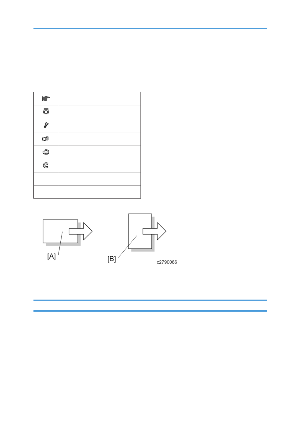
Symbols, Abbreviations and Trademarks
This manual uses several symbols and abbreviations. The meaning of those symbols and abbreviations
are as follows:
See or Refer to
Clip ring
Screw
Connector
Clamp
E-ring
SEF Short Edge Feed
LEF Long Edge Feed
[A] Short Edge Feed (SEF)
[B] Long Edge Feed (LEF)
Trademarks
Microsoft®, Windows®, and MS-DOS® are registered trademarks of Microsoft Corporation in the
United States and /or other countries.
PostScript® is a registered trademark of Adobe Systems, Incorporated.
PCL® is a registered trademark of Hewlett-Packard Company.
Ethernet® is a registered trademark of Xerox Corporation.
PowerPC® is a registered trademark of International Business Machines Corporation.
4
Page 7

Other product names used herein are for identification purposes only and may be trademarks of their
respective companies. We disclaim any and all rights involved with those marks.
5
Page 8

TABLE OF CONTENTS
Important Safety Notices...................................................................................................................................1
Prevention of Physical Injury..........................................................................................................................1
Health Safety Conditions...............................................................................................................................1
Observance of Electrical Safety Standards.................................................................................................1
Safety and Ecological Notes for Disposal...................................................................................................2
Laser Safety.....................................................................................................................................................2
The Aim of Anti-tip Components and Precautions.......................................................................................3
Warnings, Cautions, Notes...........................................................................................................................3
Symbols, Abbreviations and Trademarks.........................................................................................................4
Trademarks.....................................................................................................................................................4
1. Product Information
Specifications....................................................................................................................................................19
Product Overview.............................................................................................................................................20
Component Layout.......................................................................................................................................20
Paper Path....................................................................................................................................................21
Drive Layout..................................................................................................................................................22
Machine Codes and Peripherals Configuration............................................................................................24
Guidance for Those Who are Familiar with Predecessor Products..............................................................27
2. Installation
Installation Requirements.................................................................................................................................29
Environment..................................................................................................................................................29
Machine Level..............................................................................................................................................30
Machine Space Requirements....................................................................................................................30
Power Requirements....................................................................................................................................31
Printer Installation.............................................................................................................................................32
Power Socket for Peripherals......................................................................................................................32
Installation Flow Chart.................................................................................................................................32
Installation Procedure..................................................................................................................................34
Unpacking...........................................................................................................................................34
Installing the Toner..............................................................................................................................38
Loading Paper.....................................................................................................................................39
Turning Power On...............................................................................................................................41
Selecting the Panel Display Language..............................................................................................42
6
Page 9

Printing the Test Page..........................................................................................................................43
Settings Relevant to the Service Contract..........................................................................................43
Settings for @Remote Service (Embedded RC Gate).......................................................................44
Meter Click Charge.....................................................................................................................................47
External USB Keyboard (External Option)................................................................................................50
Moving the Machine...................................................................................................................................51
Transporting the Machine...........................................................................................................................52
Optional Unit Combinations............................................................................................................................53
Machine Options.........................................................................................................................................53
Controller Options.......................................................................................................................................53
1200 LCT (D631)............................................................................................................................................55
Component Check.......................................................................................................................................55
Installation Procedure..................................................................................................................................56
Side Fence Position Change.......................................................................................................................58
Bridge Unit (D634)..........................................................................................................................................60
Component Check.......................................................................................................................................60
Installation Procedure..................................................................................................................................60
2000-sheet booklet finisher (D637) /3000-sheet finisher (D636)............................................................64
Accessory Check..........................................................................................................................................64
Installation Procedure..................................................................................................................................65
Support Tray Installation.....................................................................................................................70
Punch Unit (D570)...........................................................................................................................................71
Component Check.......................................................................................................................................71
Installation Procedure..................................................................................................................................72
Output Jogger Unit (B703).............................................................................................................................77
Accessories...................................................................................................................................................77
Installation....................................................................................................................................................77
Mail Bin (M413)..............................................................................................................................................80
Component Check.......................................................................................................................................80
Installation Procedure..................................................................................................................................81
Anti-Condensation Heater...............................................................................................................................88
Component Check.......................................................................................................................................88
Installation Procedure..................................................................................................................................89
7
Page 10

For installing the tray heater in the main machine............................................................................89
For installing the tray heater in D580................................................................................................90
For Installing the tray heater in D581................................................................................................92
Controller Options............................................................................................................................................96
Overview......................................................................................................................................................96
I/F Card Slots......................................................................................................................................96
SD Card Slots......................................................................................................................................96
SD Card Appli Move...................................................................................................................................97
Overview.............................................................................................................................................97
Move Exec...........................................................................................................................................98
Undo Exec...........................................................................................................................................98
3. Preventive Maintenance
Maintenance Items........................................................................................................................................101
Touch Screen Calibration.............................................................................................................................102
4. Replacement and Adjustment
Beforehand.....................................................................................................................................................107
Special Tools..................................................................................................................................................108
Image Adjustment..........................................................................................................................................109
Registration................................................................................................................................................109
Image Area.......................................................................................................................................109
Leading Edge....................................................................................................................................109
Side to Side.......................................................................................................................................109
Adjustment Standard........................................................................................................................109
Paper Registration Standard............................................................................................................110
Adjustment Procedure.......................................................................................................................110
Erase Margin Adjustment..........................................................................................................................111
Color Registration......................................................................................................................................112
Line Position Adjustment...................................................................................................................112
Gamma Correction...................................................................................................................................113
Summary............................................................................................................................................113
Adjustment Procedure.......................................................................................................................115
Exterior Covers...............................................................................................................................................117
Front Door..................................................................................................................................................117
8
Page 11

Left Cover...................................................................................................................................................118
Rear Cover.................................................................................................................................................118
Top Right and Rear Cover........................................................................................................................119
Right Rear Cover.......................................................................................................................................119
Operation Panel........................................................................................................................................120
Paper Exit Cover........................................................................................................................................122
Output Tray................................................................................................................................................123
Ozone Filter...............................................................................................................................................124
Ozone filter for the charge unit.......................................................................................................124
Ozone filter for the AC Controller...................................................................................................125
Laser Optics....................................................................................................................................................126
Caution Decal Location............................................................................................................................126
LD Safety Switch........................................................................................................................................127
Error Messages.................................................................................................................................127
Laser Optics Housing Unit........................................................................................................................128
Preparing the new laser optics housing unit...................................................................................128
Before removing the old laser optics housing unit.........................................................................129
Recovery procedure for no replacement preparation of laser optics housing unit.....................129
Removing the old laser optics housing unit.....................................................................................130
Installing a new laser optics housing unit........................................................................................131
After installing the new laser optics housing unit............................................................................132
Polygon Mirror Motor and Drive Board..................................................................................................133
Airflow Fans...............................................................................................................................................135
Laser Optics Rear Right Thermistor...........................................................................................................135
Image Creation..............................................................................................................................................137
PCDU..........................................................................................................................................................137
Drum Unit and Development Unit............................................................................................................138
Developer..........................................................................................................................................141
Toner Collection Bottle..............................................................................................................................143
Second Duct Fans......................................................................................................................................144
When reinstalling the second duct fans..........................................................................................145
Third Duct Fan............................................................................................................................................145
When reinstalling the third duct fan................................................................................................146
9
Page 12

Toner Pump Unit........................................................................................................................................146
When installing the new toner pump unit.......................................................................................149
Toner End Sensor......................................................................................................................................152
Image Transfer...............................................................................................................................................153
Image Transfer Belt Cleaning Unit...........................................................................................................153
Image Transfer Belt Unit............................................................................................................................153
Image Transfer Belt....................................................................................................................................155
When reinstalling the image transfer belt.......................................................................................159
Paper Transfer................................................................................................................................................162
Paper Transfer Roller Unit.........................................................................................................................162
Paper Transfer Unit....................................................................................................................................162
ID Sensor Board........................................................................................................................................164
Cleaning for ID sensors....................................................................................................................165
After installing a new ID sensor unit/board ..................................................................................166
Temperature and Humidity Sensor..........................................................................................................166
Drive Unit........................................................................................................................................................167
Gear Unit...................................................................................................................................................167
When installing the drive unit...........................................................................................................174
Adjustment after replacing the gear unit.........................................................................................174
Registration Motor.....................................................................................................................................175
Paper Feed Motor.....................................................................................................................................176
Drum/Development Motors for M, C, and Y.........................................................................................177
Drum/Development Motor-K...................................................................................................................178
ITB Drive Motor.........................................................................................................................................179
Fusing/Paper Exit Motor..........................................................................................................................179
Image Transfer Belt Contact Motor..........................................................................................................180
Duplex Inverter Motor...............................................................................................................................180
Pressure Roller Contact Motor..................................................................................................................182
Duplex/By-pass Motor.............................................................................................................................183
Paper Transfer Contact Motor..................................................................................................................185
Toner Transport Motor..............................................................................................................................187
Toner Collection Unit.................................................................................................................................188
Paper Feed Clutches.................................................................................................................................188
10
Page 13

Development Clutch-Y..............................................................................................................................191
Development Clutches for M and C........................................................................................................192
Development Clutch-K..............................................................................................................................193
Fusing..............................................................................................................................................................195
Fusing Unit..................................................................................................................................................195
Fusing Exit Shutter Plate............................................................................................................................197
Fusing Entrance Guide Plate.....................................................................................................................197
Cleaning Requirement......................................................................................................................199
Fusing Exit Guide Plate Cleaning Procedure...........................................................................................199
Fusing Unit Upper Cover..........................................................................................................................200
Fusing Unit Lower Cover...........................................................................................................................201
Fusing Sleeve Belt Unit..............................................................................................................................202
Oil Absorber Felt..............................................................................................................................205
Pressure Roller............................................................................................................................................206
Stripper Plate.............................................................................................................................................208
Cleaning Requirement......................................................................................................................209
Pressure Roller Thermistors........................................................................................................................209
Pressure Roller Thermostats.......................................................................................................................210
NC Sensors................................................................................................................................................210
Fusing Fan..................................................................................................................................................211
When installing the fusing fan..........................................................................................................212
Paper Exit Fan............................................................................................................................................212
When installing the paper exit fan..................................................................................................213
AC Controller Board Fan..........................................................................................................................213
When installing the AC controller fan.............................................................................................214
Fusing Entrance Thermopiles....................................................................................................................214
When cleaning the lens of the thermopile......................................................................................215
Pressure Roller HP Sensor.........................................................................................................................215
QSU fan.....................................................................................................................................................216
Fusing Unit Shutter Plate Drive Motor......................................................................................................218
Fusing Unit Shutter Plate Home Position Sensor......................................................................................218
Fusing Unit Shutter Plate Drive Mechanism.............................................................................................219
Paper Feed.....................................................................................................................................................222
11
Page 14

Paper Feed Unit.........................................................................................................................................222
Pick-Up, Feed and Separation Rollers.....................................................................................................223
Tray 1 and Tray 2.............................................................................................................................223
Tray Lift Motor............................................................................................................................................224
Vertical Transport, Paper Overflow, Paper End and Paper Feed Sensor.............................................224
Registration Sensor....................................................................................................................................225
By-pass Paper Size Sensor and By-pass Paper Length Sensor.............................................................226
When reinstalling the by-pass paper size sensor..........................................................................227
By-pass Bottom Tray..................................................................................................................................228
By-pass Paper End Sensor........................................................................................................................231
By-pass Pick-up, Feed and Separation Roller, Torque Limiter...............................................................232
By-pass Feed Clutch..................................................................................................................................233
Paper Exit Unit...........................................................................................................................................234
Fusing Exit, Paper Overflow, Junction Paper Jam and Paper Exit Sensor............................................235
Duplex Unit.....................................................................................................................................................237
Duplex Unit................................................................................................................................................237
Duplex Door Sensor..................................................................................................................................238
Duplex Entrance Sensor............................................................................................................................239
Duplex Exit Sensor....................................................................................................................................240
Electrical Components...................................................................................................................................241
Boards........................................................................................................................................................241
Controller Box closed.......................................................................................................................241
Behind the IOB..................................................................................................................................242
Controller Box Open........................................................................................................................242
Controller Unit...........................................................................................................................................243
Controller Box Right Cover.......................................................................................................................243
Controller Box............................................................................................................................................243
When opening the controller box...................................................................................................243
When removing the controller box.................................................................................................244
IOB (In/Out Board)..................................................................................................................................247
BB (Bridge Board).....................................................................................................................................248
BCU............................................................................................................................................................248
When installing the new BCU..........................................................................................................249
12
Page 15

PSU.............................................................................................................................................................250
PSU bracket.......................................................................................................................................250
PSU board.........................................................................................................................................250
PSU fans............................................................................................................................................251
Shutdown Switch.......................................................................................................................................252
ITB Power Supply Board...........................................................................................................................253
High Voltage Supply Board.....................................................................................................................254
High Voltage Supply Board Bracket.......................................................................................................254
AC Controller Board.................................................................................................................................255
AC Controller Board Bracket...................................................................................................................255
Controller Board........................................................................................................................................256
When installing the new controller board......................................................................................258
HDD Fan....................................................................................................................................................258
When installing the HDD fan...........................................................................................................259
HDD............................................................................................................................................................259
When installing a new HDD unit.....................................................................................................260
Toner Bottle Detection Board...................................................................................................................260
NVRAM Replacement Procedure............................................................................................................261
NVRAM on the BCU........................................................................................................................261
NVRAM on the controller board.....................................................................................................262
Tube Cooling Fan (1st Duct Fan).............................................................................................................263
Using Dip Switches........................................................................................................................................264
Controller Board........................................................................................................................................264
BCU Board.................................................................................................................................................264
5. System Maintenance
Service Program Mode.................................................................................................................................265
SP Tables....................................................................................................................................................265
Enabling and Disabling Service Program Mode....................................................................................265
Entering SP Mode.............................................................................................................................265
Exiting SP Mode...............................................................................................................................265
Types of SP Modes....................................................................................................................................265
SP Mode Button Summary...............................................................................................................266
Selecting the Program Number.......................................................................................................267
13
Page 16

Exiting Service Mode.......................................................................................................................268
Service Mode Lock/Unlock............................................................................................................268
Remarks......................................................................................................................................................268
Display on the Control Panel Screen..............................................................................................268
Others................................................................................................................................................268
Service SP Table............................................................................................................................................270
SP1-XXX (Service Mode)..........................................................................................................................270
Engine SP Tables-1........................................................................................................................................285
SP1-XXX (Feed).........................................................................................................................................285
Engine SP Tables-2........................................................................................................................................299
SP2-XXX (Drum).........................................................................................................................................299
Engine SP Tables-3........................................................................................................................................307
SP3-XXX (Process).....................................................................................................................................307
Engine SP Tables-4........................................................................................................................................327
SP5-XXX (Mode).......................................................................................................................................327
Engine SP Tables-5........................................................................................................................................382
SP6-XXX (Peripherals)...............................................................................................................................382
Engine SP Tables-6........................................................................................................................................390
SP7-XXX (Data Log)..................................................................................................................................390
Input and Output Check................................................................................................................................440
Input Check Table.....................................................................................................................................440
Printer.................................................................................................................................................440
Table 1: Paper Height Sensor..........................................................................................................443
Table 2: Paper Size Switch (Tray 2)...............................................................................................443
Table 3: Paper Size (By-pass Table)...............................................................................................444
[FIN (EUP) INPUT Check] Finisher (D636/ D637).......................................................................445
[FIN (JAK) INPUT Check] 4bin Mail Box (M413)........................................................................447
Bridge Unit (D634)...........................................................................................................................448
Two-Tray Paper Feed Unit (D580)/ LCT 2000 (D581)/ LCT 1200 (D631)............................448
Output Check Table..................................................................................................................................449
Printer.................................................................................................................................................449
[FIN (EUP) OUTPUT Check] (Booklet) Finisher (D636/D637)....................................................455
FIN(JAK)OUTPUT Check 4bin Mail Box (M413).........................................................................457
14
Page 17

Bridge Unit (D634)...........................................................................................................................457
4bin Mail Box (M413)....................................................................................................................457
Two-Tray Paper Feed Unit (D580)/ LCT 2000 (D581)/ LCT 1200 (D631)............................457
Firmware Update...........................................................................................................................................459
Type of Firmware.......................................................................................................................................459
Before You Begin.......................................................................................................................................460
Updating Firmware...................................................................................................................................461
Preparation........................................................................................................................................461
Updating Procedure.........................................................................................................................461
Error Messages.................................................................................................................................462
Firmware Update Error.....................................................................................................................462
Recovery after Power Loss...............................................................................................................463
Updating the LCDC for the Operation Panel..........................................................................................463
Handling Firmware Update Errors...........................................................................................................464
Error Message Table........................................................................................................................464
NVRAM Data Upload/Download..............................................................................................................466
Uploading Content of NVRAM to an SD card.......................................................................................466
Downloading an SD Card to NVRAM....................................................................................................467
Address Book Upload/Download..............................................................................................................469
Information List...........................................................................................................................................469
Download..................................................................................................................................................469
Upload.......................................................................................................................................................470
Using the Debug Log.....................................................................................................................................471
Overview....................................................................................................................................................471
Switching ON and Setting UP Save Debug Log.....................................................................................471
Retrieving the Debug Log from the HDD.................................................................................................475
Debug Log Codes.....................................................................................................................................476
SP5857-015 Copy SD Card-to-SD Card: Any Desired Key.......................................................476
SP5857-016 Create a File on HDD to Store a Log......................................................................476
SP5857-017 Create a File on SD Card to Store a Log................................................................476
Card Save Function.......................................................................................................................................477
Overview....................................................................................................................................................477
Card Save:........................................................................................................................................477
15
Page 18

Procedure...................................................................................................................................................477
Error Messages..........................................................................................................................................481
SMC List Card Save Function.......................................................................................................................482
Overview....................................................................................................................................................482
SMC List Card Save.........................................................................................................................482
Procedure...................................................................................................................................................482
File Names of the Saved SMC Lists.........................................................................................................484
Error Messages..........................................................................................................................................485
6. Troubleshooting
Service Call....................................................................................................................................................487
Service Call Conditions.............................................................................................................................487
SC Code Classification....................................................................................................................488
SC Table.........................................................................................................................................................491
Service Call Tables - 1..............................................................................................................................491
SC1xx: Scanning..............................................................................................................................491
Service Call Tables - 2..............................................................................................................................491
SC 2xx: Exposure.............................................................................................................................491
Service Call Tables - 3..............................................................................................................................498
SC3xx: Image Processing – 1.........................................................................................................498
SC3xx: Image Processing – 2.........................................................................................................499
Service Call Tables - 4..............................................................................................................................503
SC4xx: Image Processing - 3..........................................................................................................503
Service Call Tables - 5..............................................................................................................................509
SC5xx: Paper Feed and Fusing.......................................................................................................509
Service Call Tables - 6..............................................................................................................................529
SC6xx: Device Communication.......................................................................................................529
Service Call Tables - 7..............................................................................................................................543
SC7xx: Peripherals...........................................................................................................................543
Service Call Tables - 8..............................................................................................................................553
SC8xx: Overall System....................................................................................................................553
Service Call Tables - 9..............................................................................................................................569
SC9xx: Miscellaneous.....................................................................................................................569
Process Control Error Conditions..................................................................................................................577
16
Page 19

Developer Initialization Result..................................................................................................................577
Process Control Self-Check Result............................................................................................................578
Vsg Adjustment Result.......................................................................................................................580
Line Position Adjustment Result.................................................................................................................580
Troubleshooting Guide..................................................................................................................................582
Image Quality............................................................................................................................................582
Line Position Adjustment............................................................................................................................584
Test.....................................................................................................................................................585
Countermeasure list for color registration errors............................................................................585
Stain on the Outputs..................................................................................................................................591
Problem at Regular Intervals.....................................................................................................................592
Toner End Recovery Error.........................................................................................................................592
Flow Chart for the Toner End Recovery Error.................................................................................593
Toner Bottle Detection Error......................................................................................................................594
Solid Image or Halftone Image Error......................................................................................................595
Recovery Procedure.........................................................................................................................595
Problem Prevention Procedure.........................................................................................................596
Faulty Cleaning..........................................................................................................................................596
Black or color lines (2-3mm)...........................................................................................................596
Band Image Between 20mm and 30mm.......................................................................................597
Encryption Key Restoration for NVRAM..................................................................................................597
How to restore the old encryption key to the machine..................................................................597
How to do a forced start up with no encryption key.....................................................................598
Other Symptoms........................................................................................................................................599
Flowchart for the error......................................................................................................................600
Countermeasure list for the error.....................................................................................................600
Jam Detection.................................................................................................................................................603
Paper Jam Display.....................................................................................................................................603
Jam Codes and Display Codes................................................................................................................603
Paper Size Code...............................................................................................................................608
Sensor Locations...............................................................................................................................610
Electrical Component Defects.......................................................................................................................611
Sensors.......................................................................................................................................................611
17
Page 20

Blown Fuse Conditions..............................................................................................................................616
Power Supply Unit............................................................................................................................616
AC Drive Board................................................................................................................................616
7. Energy Saving
Energy Save...................................................................................................................................................619
Energy Saver Modes................................................................................................................................619
Timer Settings....................................................................................................................................619
Return to Stand-by Mode.................................................................................................................620
Recommendation..............................................................................................................................620
Energy Save Effectiveness........................................................................................................................620
Paper Save.....................................................................................................................................................622
Effectiveness of Duplex/Combine Function............................................................................................622
1. Duplex:..........................................................................................................................................622
2. Combine mode:............................................................................................................................622
3. Duplex + Combine:......................................................................................................................623
How to calculate the paper reduction ratio ..................................................................................623
18
Page 21

1. Product Information
Specifications
See "Appendices" for the following information:
• General Specifications
• Supported Paper Sizes
• Software Accessories
• Optional Equipment
19
Page 22
1. Product Information
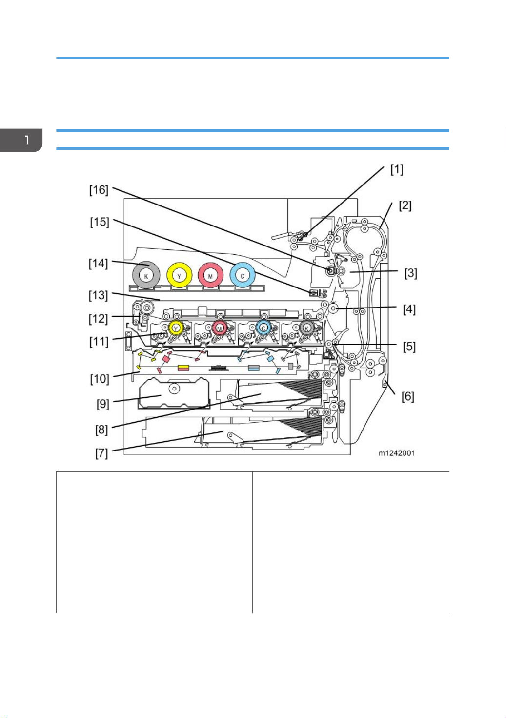
Product Overview
Component Layout
20
1. Paper exit rollers
2. Duplex unit
3. Fusing unit
4. Paper transfer roller
5. Registration roller
6. By-pass feed table
7. Tray 2
8. Tray 1
9. Toner collection bottle
10. Laser optics housing unit
11. PCDU (4 colors)
12. Image transfer belt cleaning unit
13. Image transfer belt unit
14. Toner bottle (4 colors)
15. ID sensor
16. Fusing sleeve belt unit
Page 23
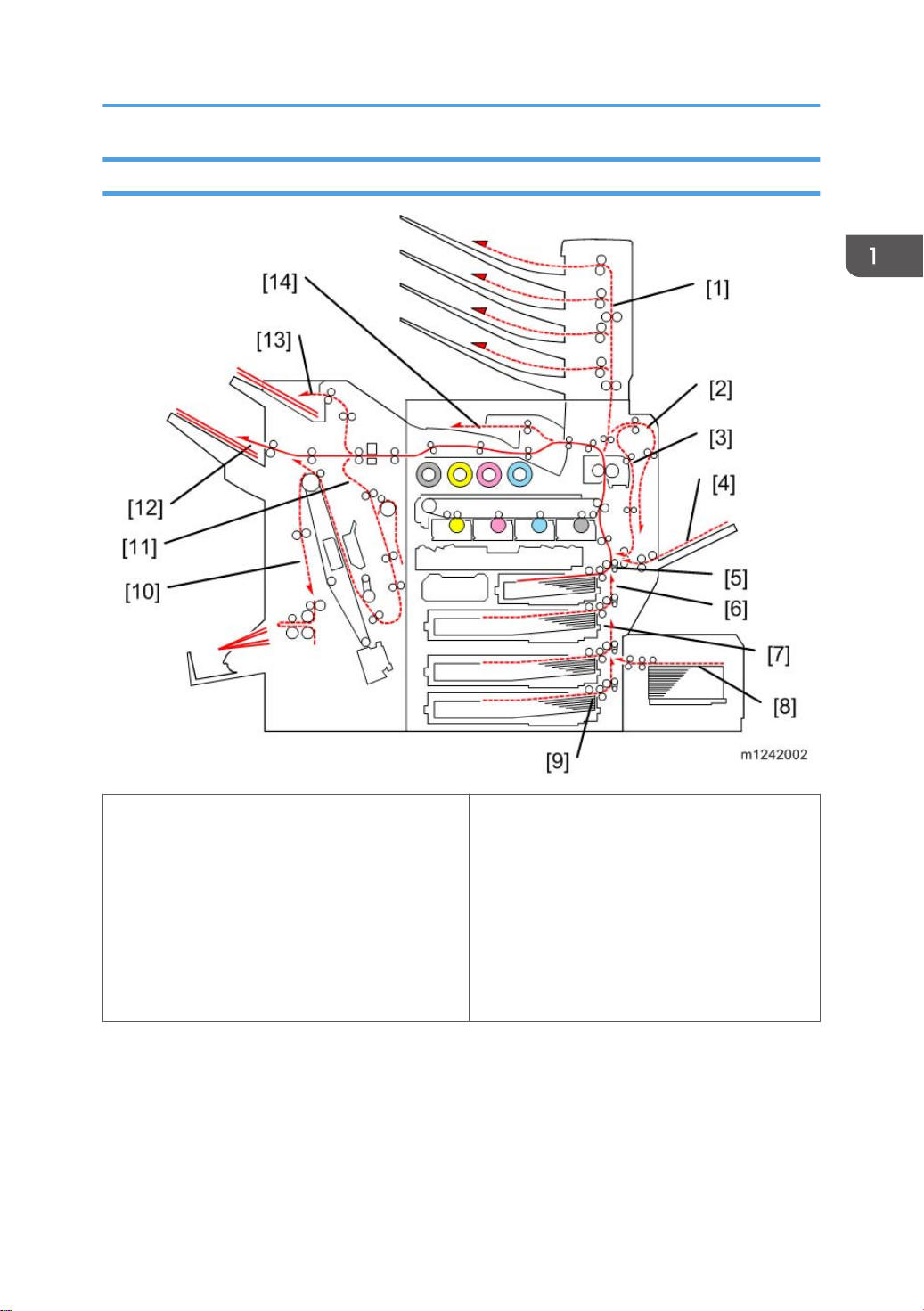
Paper Path
Product Overview
1. Mail bin
2. Duplex inverter
3. Duplex feed
4. By-pass tray feed
5. Tray 1 feed
6. Tray 2 feed
7. Tray 3: Optional paper feed unit/LCT
The 2000/3000-sheet (booklet) finisher requires the bridge unit and one from the two-tray paper feed
unit or the LCT.
8. Tray 5: Optional LCT 1200
9. Tray 4: Optional paper feed unit
10. Finisher booklet stapler (Optional)
11. Finisher stapler (Optional)
12. Finisher upper tray (Optional)
13. Finisher proof tray (Optional)
14. Output tray
21
Page 24
1. Product Information
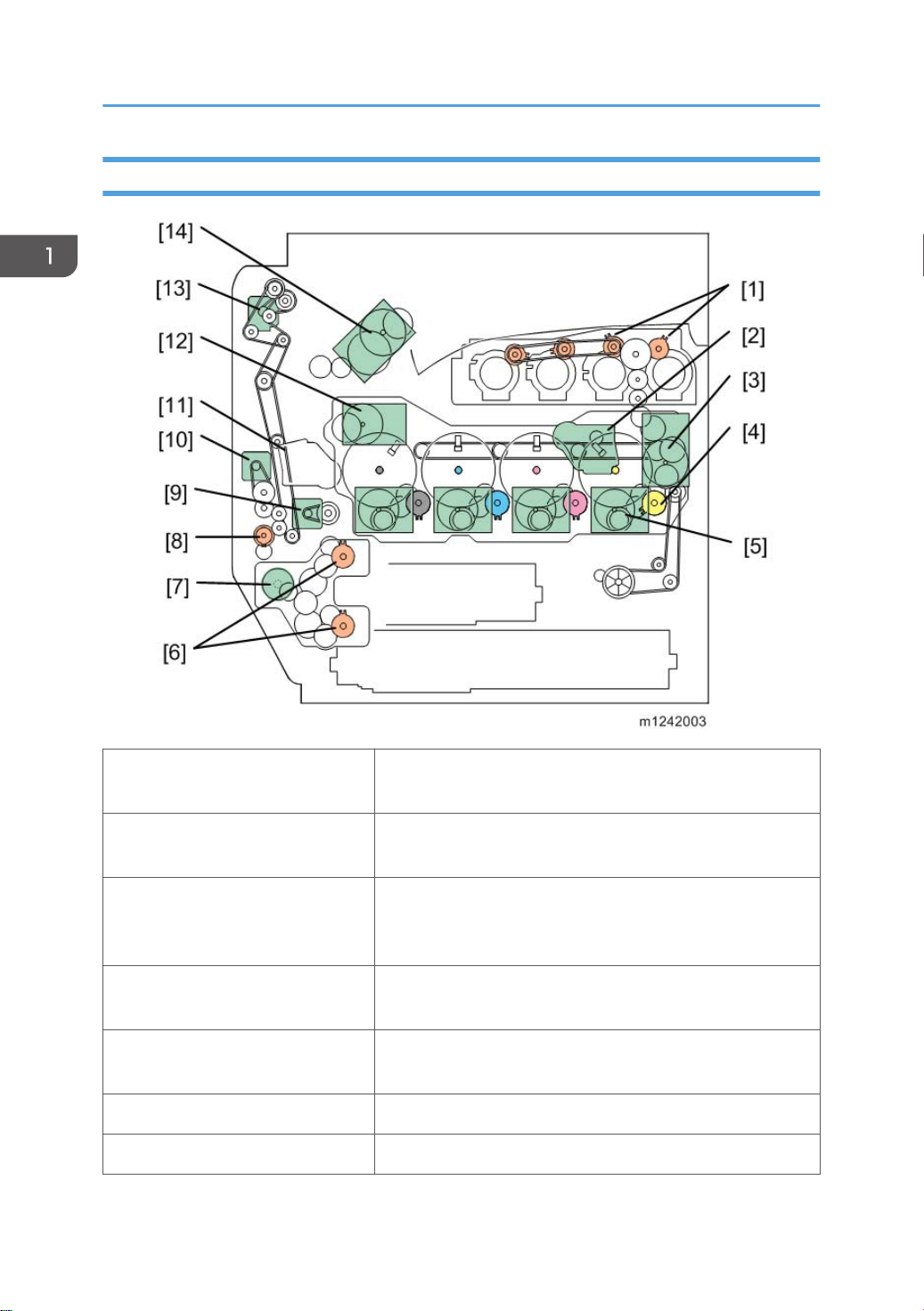
Drive Layout
22
1. Toner supply clutch-K and -CMY:
2. ITB (Image Transfer Belt) contact
motor:
3. Toner transport motor:
4. Development clutch (K, Y, M, C):
5. Drum/Development drive motor
(K, Y, M, C):
6. Paper feed clutch: Switches the drive power between tray 1 and tray 2.
7. Paper feed motor: Drives the paper feed mechanisms (tray 1/tray 2).
Turns on/off the drive power to the toner supply unit (K and CMY).
Moves the ITB into contact and away from the color PCDUs.
Drives the toner attraction pumps and the toner collection coils
from the PCDUs, from the transfer belt unit, and inside the
toner collection bottle. Also rotates the toner bottles.
Turns on/off the drive power to the development unit (K, Y,
M, C).
Drives the color drum unit and development unit (K, Y, M, C).
Page 25

Product Overview
8. By-pass feed clutch:
Turns on/off the drive power to the by-pass pick-up, feed and
separation rollers.
9. Registration motor: Drives the registration roller.
10. By-pass/duplex feed motor:
11. Paper transfer contact motor:
Drives the by-pass pick-up, feed and separation roller, and
duplex transport rollers.
Moves the paper transfer roller in contact with the image
transfer belt.
12. ITB drive motor: Drives the image transfer belt unit.
13. Duplex inverter motor: Drives the duplex inverter rollers and duplex transport rollers.
14. Fusing/paper exit motor: Drives the fusing unit and paper exit section.
23
Page 26
1. Product Information
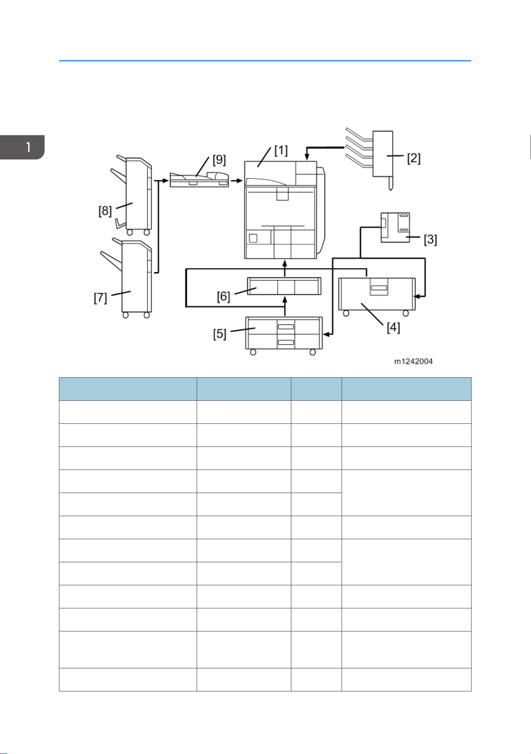
Machine Codes and Peripherals Configuration
Item Machine Code Call out Remarks
Mainframe M124/M125 [1] -
Mail bin M413 [2] -
1200-sheet LCT D631 [3] Requires [4] or [5]
2000-sheet LCT D581 [4]
One from the two
Two-tray paper feed unit D580 [5]
One-tray paper feed unit D579 [6] -
3000-sheet finisher D636 [7]
2000-sheet booklet finisher D637 [8]
Punch unit 2/3 holes D570-00 (NA) - Requires [7] or [8]
Punch unit 2/4 holes D570-01 (EU) - Requires [7] or [8]
Punch unit 4 holes
Bridge unit D634 [9] -
D570-02
(Scandinavia)
- Requires [7] or [8]
One from [7] and [8];
Requires one from [4] and [5]
24
Page 27
Machine Codes and Peripherals Configuration
Item Machine Code Call out Remarks
Output jogger unit B703 - Requires [7]
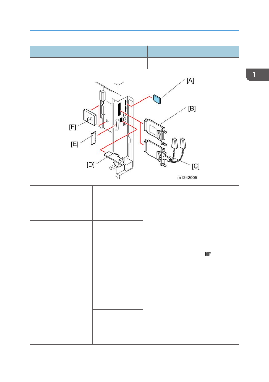
Item Machine code Call out Remark
PictBridge D645-15
IPDS Unit M416-24
SD Card for Netware
Printing
M416-29
[A]
D640-21 (NA)
VM Card
D640-22 (EU)
D640-23 (AA)
IEEE 1284 B679 [B]
M344-01 (NA)
Wireless LAN
[C]M344-02 (EU)
M344-08 (EU/AA)
M416-30
Gigabit Ethernet
[D] -
D377
Those cards should be
installed from SD slot 2
(lower).
If multiple applications are
required, merge all
applications in one SD card
with SP mode. ( p.97 "SD
Card Appli Move")
You can only install one of
these at a time.
25
Page 28

1. Product Information
512MB Memory Option M354-03
[E] -
1GB Memory Option M416-27
HDD*1 (250GB) M416-28 [F] -
Data Overwrite Security,
HDD Encryption
The hard disk (M416-28) is supplied with the M125 model as standard equipment.
*1
- - Included in the controller ROM
26
Page 29

Guidance for Those Who are Familiar with Predecessor Products
Guidance for Those Who are Familiar with
Predecessor Products
Machines M124/M125 are successor models to Machines G188/G189. If you have experience with
the predecessor products, the following information will be of help when you read this manual.
Different Points from Predecessor Products
Item M124/M125 G188/G189
Controller Type GW+ Controller GW Controller
New Fusing Unit without the
Decurler
Fusing Unit NEW QSU-DH fusing system IH roller fusing system
SMC data SD card download or printing Printing only
Operation Panel Tiltable Operation Panel
Includes USB/SD slot
USB2.0/SD Slot Standard Optional
Data Overwrite Security,
HDD Encryption
Included in the controller ROM SD card
Yes No
Stationary Operation Panel
27
Page 30

1. Product Information
28
Page 31

2. Installation
Installation Requirements
Environment
1. Temperature Range: 10°C to 32°C (50°F to 89.6°F)
2. Humidity Range: 15% to 80% RH
3. Ambient Illumination: Less than 1500 lux (do not expose to direct sunlight)
4. Ventilation: 3 times/hr/person or more
5. Do not let the machine get exposed to the following:
1) Cool air from an air conditioner
2) Heat from a heater
6. Do not install the machine in areas that are exposed to corrosive gas.
7. Install the machine at locations lower than 2,000 m (6,560 ft.) above sea level.
8. Install the machine on a strong, level base. (Inclination on any side must be no more than 5 mm.)
9. Do not install the machine in areas that get strong vibrations.
• Do not leave the toner bottle in a place directly exposed to sunlight.
29
Page 32

2. Installation
• The toner bottle must be kept at a temperature of 35°C (95°F) or less. Be careful not to leave the
toner bottle in a hot place when transporting or storing it.
Machine Level
Front to back: Within 5 mm (0.2")
Right to left: Within 5 mm (0.2")
Machine Space Requirements
• This machine, which uses high voltage power sources, can generate ozone gas. High ozone
density is harmful to human health. Therefore, the machine must be installed in a well-ventilated
room.
A: Over 100 mm (3.9")
B: Over 100 mm (3.9")
C: Over 100 mm (3.9")
D: Over 750 mm (29.5")
Put the machine near the power source with the clearance shown above.
30
Page 33

Power Requirements
• Insert the plug firmly in the outlet.
• Do not use an outlet extension plug or cord.
• Ground the machine.
1. Input voltage level:
120 to 127 V, 60 Hz: More than 12 A (NA)
220 V to 240 V, 50 Hz/60 Hz: 10 A (EU/AA/China)
2. Permissible voltage fluctuation: +8.66 %/ -10 % (NA)
Permissible voltage fluctuation: ± 10 % (Others)
3. Do not put things on the power cord.
Installation Requirements
31
Page 34

2. Installation
Printer Installation
• Make sure that the image transfer belt is in its correct position (away from the PCDUs) before you
move the machine. Otherwise, the image transfer belt and the black PCDU can be damaged.
Power Socket for Peripherals
• Rating voltage for peripherals.
• Make sure to plug the cables into the correct sockets.
Installation Flow Chart
This flow chart shows the best procedure for installation.
32
Page 35

Printer Installation
You need the optional paper tray unit or the LCT if you want to install the finisher (D636 or D637) or
1200-sheet LCT (D631).
The punch unit is for 2000-sheet booklet finisher (D637) and 3000-sheet finisher (D636).
33
Page 36

2. Installation
Installation Procedure
• Remove the tape from the development units before you turn the main switch on. The development
units can be severely damaged if you do not remove the tape.
Put the machine on the paper tray unit or the LCT first if you install an optional paper tray unit or the
optional LCT at the same time. Then install the machine and other options.
• Keep the shipping retainers after you install the machine. You may need them in the future if you
transport the machine to another location.
Unpacking
• When lifting the machine, use the handle and grips on both sides of the machine.
• If not, the machine could be dropped. This may cause an injury and may damage the machine.
1. Pull out the handle [A].
34
Page 37

Printer Installation
2. Lift the machine with four people by using the handle and grips on both sides of the machine.
• Do not remove the tapes before placing the machine.
• Lower the machine slowly and carefully, so as not to pinch your hands.
3. Push back the handle [A] into the machine.
35
Page 38

2. Installation
4. Push up the lever [C] on the right door, and then open the right door.
36
5. Remove the tape [A].
6. Close the right door.
Page 39
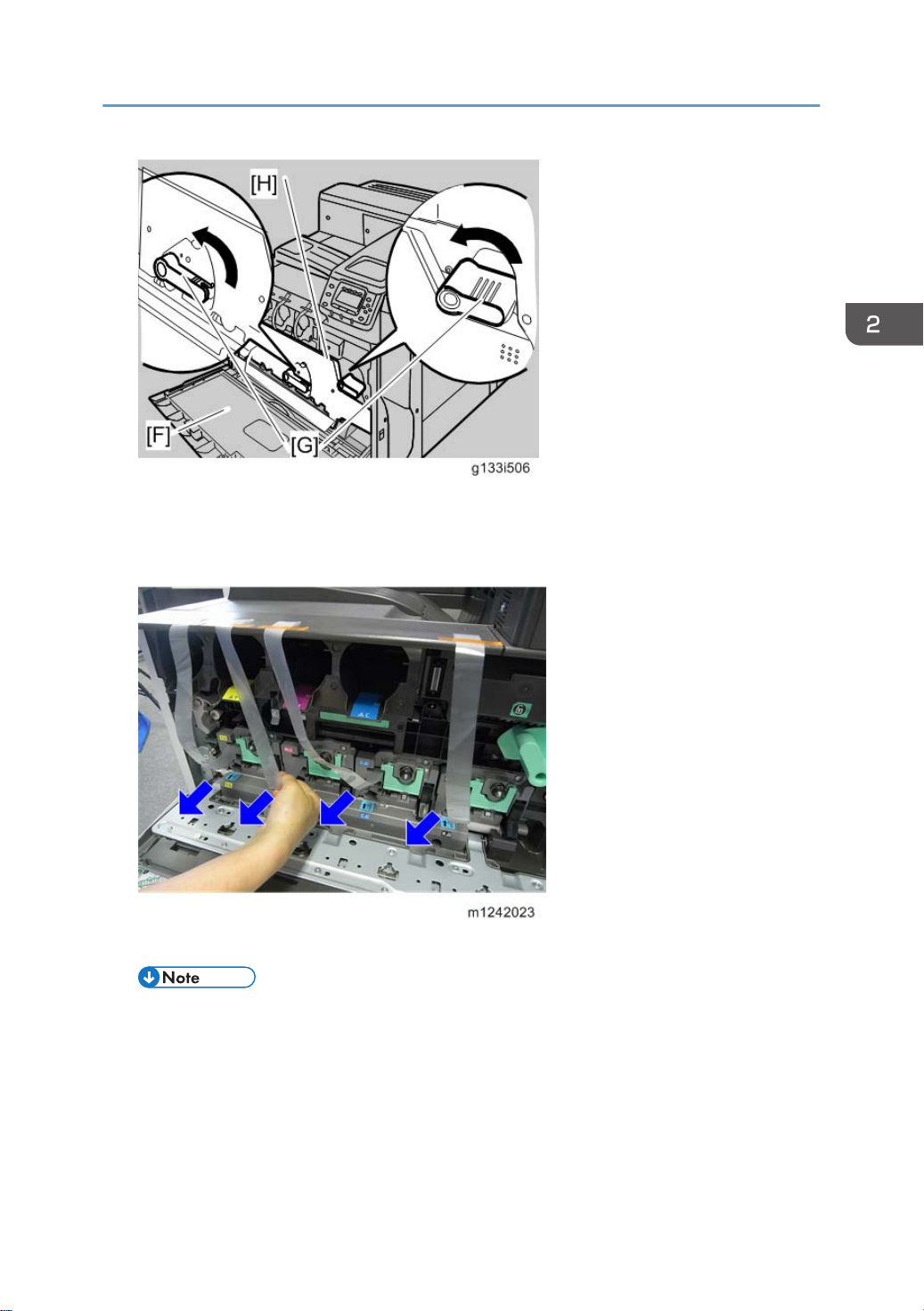
7. Open the front door [F].
8. Turn the two green levers [G] counterclockwise.
9. Open the drum positioning plate [H].
Printer Installation
10. Remove and pull out the four tapes horizontally from all PCUs.
• Make sure that all tapes are removed.
11. Close the drum positioning plate.
12. Turn the green levers clockwise to lock the levers.
37
Page 40

2. Installation
Installing the Toner
1. Shake the toner bottle up and down five or six times before installing.
38
2. Insert the each toner bottle into the machine with the label facing up.
3. Close the front door.
Page 41
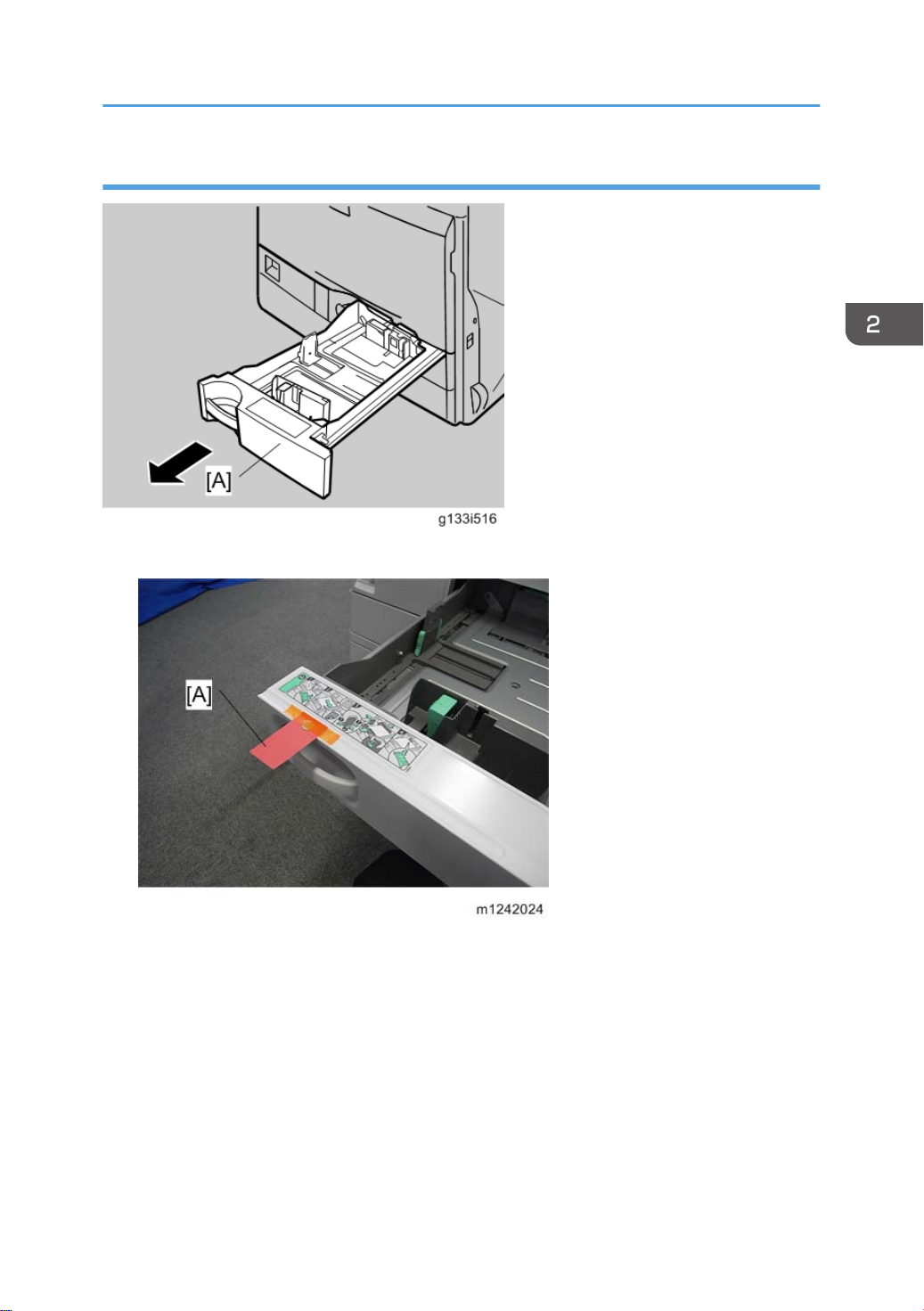
Loading Paper
1. Pull out the tray 1 [A] of the machine.
Printer Installation
2. Remove the tape [A].
3. Take out the contents from tray 1.
39
Page 42

2. Installation
4. Adjust the end plate [A] to A4 LEF/Letter LEF size.
5. Load paper in tray 1, and then close tray 1.
40
6. Attach the tray number decals to the trays.
Page 43
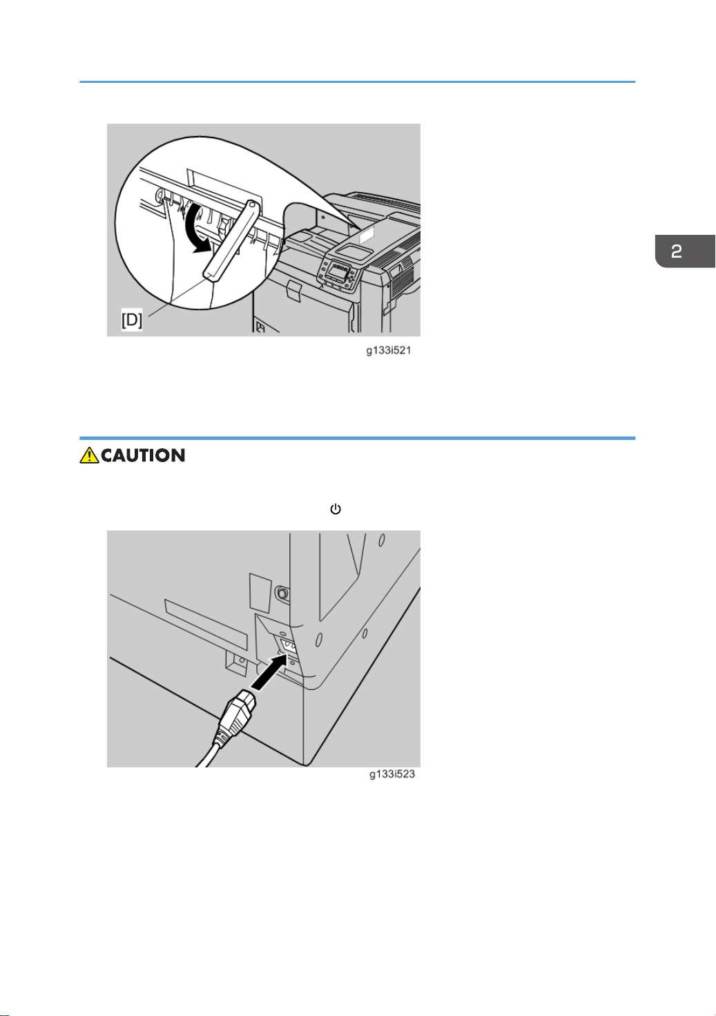
7. Pull out the feeler [D] for the output-tray-full detection mechanism.
Turning Power On
Printer Installation
• Turn off the power switch whenever you plug in and unplug the power cord.
1. Make sure that the power switch is set to " " (Standby).
2. Plug in the machine.
41
Page 44

2. Installation
3. Turn on the power switch.
• Do not turn off the power switch until initialization is completed (‘Ready’ appears on the display
when initialization is completed). Otherwise, the machine may malfunction.
Selecting the Panel Display Language
To change the panel display language, it is necessary to register available languages in the User Tools.
Specify the settings according to the following procedure.
• You can select one of these languages (the default is English): Japanese, English, German, French,
Italian, Dutch, Swedish, Norwegian, Danish, Spanish, Finnish, Portuguese, Czech, Polish,
Hungarian, Simplified Chinese, Russian, Greek, Catalan, Turkish, or Brazilian Portuguese.
• You do not have to do this procedure if you use English. Do this procedure if you want to use a
different language.
1. Turn on the power switch of the machine.
42
Page 45

Printer Installation
• “Ready” shows on the panel display after the machine warms up.
2. Press the "User Tools" key.
3. Press "Administrator Tools" in "System Settings".
4. Press "Select Switchable Languages".
5. Using the language button displayed on the User Tools screen, select the required language (this
will then be selectable at any time with a toggle setting), and then press "OK".
• Only languages available for the machine are displayed.
• At least one language must be selected.
6. Return to the User Tools menu, and then keep pressing the language button until the language you
want to select appears.
• The language selected in "Select Switchable Languages" becomes available for selection by
a toggle setting.
Printing the Test Page
1. You can check if the machine works correctly by printing a test page such as the configuration
page. However, you cannot check the connection between the machine and the computer by
printing the test page.
2. Turn on the power switch.
3. Press the "User Tools" key.
4. Press "Printer Features".
5. Press "List/Test Print".
6. Press "Configuration Page".
7. The test printing starts shortly after.
8. Turn off the power switch.
Settings Relevant to the Service Contract
Change the necessary settings depending on the each customer's service contract. For details, refer to
"Meter Click Charge" following this section.
43
Page 46

2. Installation
Settings for @Remote Service (Embedded RC Gate)
• Prepare and check the following check points before you visit the customer site. For details, ask the
@Remote key person.
Check points before making @Remote settings
1. The setting of SP5816-201 in the mainframe must be "0".
2. Print the SMC with SP5990-002 and then check if a device ID2 (SP5811-003) must be correctly
programmed.
• 6 spaces must be put between the 3-digit prefix and the following 8-digit number (e.g.
xxx______xxxxxxxx).
• ID2 (SP5811-003) and the serial number (SP5811-001) must be the same (e.g. ID2:
A01______23456789 = serial No. A0123456789)
3. The following settings must be correctly programmed.
• Proxy server IP address (SP5816-063)
• Proxy server Port number (SP5816-064)
• Proxy User ID (SP5816-065)
• Proxy Password (SP5816-066)
4. Get a Request Number.
5. Execute the @Remote Settings.
6. Enter the SP mode.
7. Input the Request number which you have obtained from @Remote Center GUI, and then press the
"OK" key with SP5816-202.
8. Confirm the Request number, and then press the "EXECUTE" key with SP5816-203.
9. Check the confirmation result with SP5816-204.
Value
Meaning Solution/ Workaround
0 Succeeded -
1 Request number error Check the request number again.
Communication error (proxy
3
enabled)
Communication error (proxy
4
disabled)
Check the network condition.
Check the network condition.
44
Proxy error (Illegal user name or
5
password)
Check Proxy user name and password.
Page 47

Printer Installation
Value Meaning Solution/ Workaround
6 Communication error Check the network condition.
8 Other error See "SP5816-208 Error Codes" below this.
Request number confirmation
9
executing
Processing… Please wait.
10. Make sure that the screen displays the Location Information with SP5816-205 only when it has
been input at the Center GUI.
11. Press the "EXECUTE" key to execute the registration with SP5816-206.
12. Check the registration result with SP5816-207.
Value Meaning Solution/ Workaround
0 Succeeded -
1 Request number error Check the request number again.
2 Already registered Check the registration status.
Communication error (proxy
3
enabled)
Communication error (proxy
4
disabled)
Proxy error (Illegal user name or
5
password)
8 Other error See "SP5816-208 Error Codes" below this.
Request number confirmation
9
executing
13. Exit the SP mode.
Check the network condition.
Check the network condition.
Check Proxy user name and password.
Processing… Please wait.
45
Page 48

2. Installation
SP5816-208 Error Codes
Cause Code Meaning Solution/ Workaround
Operation Error,
Incorrect Setting
-12002
Inquiry, registration attempted
without acquiring Request No.
-12003 Attempted registration without
execution of a confirmation and no
previous registration.
-12004 Attempted setting with illegal entries
for certification and ID2.
-12005 @Remote communication is
prohibited. The device has an
Embedded RC gate-related
problem.
-12006 A confirmation request was made
after the confirmation had been
already completed.
-12007 The request number used at
registration was different from the
one used at confirmation.
Obtain a Request Number
before attempting the Inquiry or
Registration.
Perform Confirmation before
attempting the Registration.
Check ID2 of the mainframe.
Make sure that "Remote
Service" in User Tools is set to
"Do not prohibit".
Execute registration.
Check Request No.
46
-12008
Update certification failed because
mainframe was in use.
-12009 The ID2 in the NVRAM and that of
the certificate does not match.
-12010 The certificate domain has not been
initialized.
Check the mainframe
condition. If the mainframe is in
use, try again later.
-
-
Page 49

Printer Installation
Cause Code Meaning Solution/ Workaround
-2385 Other error -
Error Caused by
Response from
GW URL
-2387 Not supported at the Service
Center
-2389 Database out of service -
-2390 Program out of service -
-2391
-2392 Parameter error -
-2393 External RCG not managed -
-2394 Mainframe not managed -
-2395 Box ID for external RCG is illegal. -
-2396
-2397 Incorrect ID2 format
-2398 Incorrect request number format Check the Request No.
Two registrations for the same
mainframe
Mainframe ID for external RCG is
illegal.
-
Check the registration
condition of the mainframe
-
Check the ID2 of the
mainframe.
Meter Click Charge
Basically, there are two ways to set up this function.
Meter click change enabled (SP 5-930-001 set to ‘enabled’): The counter can be displayed and
printed by the customer. The technician can then call the customer and ask them to read the counter.
Meter click charge disabled (SP 5-930-001 set to ‘disabled’; this is the default setting): The counter
cannot be displayed or printed by the customer. To check the counter, the technician must print the SMC
report (SP 5-990).
• You must select one of the counter methods (developments/prints) in accordance with the contract
(* SP5-045-001).
47
Page 50

2. Installation
48
Item SP No. Function Default
Page 51

Meter Click
Charge
Meter Click
Charge: PCU
SP5-930-001
SP5-930-010
Enables or disables Meter Click Charge.
When enabled:
• The counter menu shows
immediately after you push the
"Menu" key. The "Counter Method"
(SP5-045) sets the type of the
counter.
• You can print the counter from the
counter menu.
When disabled:
• The counter menu does not show.
Enables or disables the PM alert for the
PCUs.
If this SP is enabled, an alert message is
displayed when the PCUs need to be
replaced.
Printer Installation
"0": OFF
"1": No alert
Meter Click
Charge:
Image
Transfer Belt
Unit
Meter Click
Charge:
Fusing Unit
Counter
method
A3/DLT
double count
SP5-930-014
SP5-930-016
SP5-045-001
SP5-104-001
Enables or disables the PM alert for the
image transfer belt unit.
If this SP is enabled, an alert message is
displayed when the image transfer belt
unit needs to be replaced.
Enables or disables the PM alert for the
fusing unit.
If this SP is enabled, an alert message is
displayed when the fusing unit needs to
be replaced.
Specifies if the counting method used in
meter charge mode is based on
developments or prints.
Specifies whether the counter is doubled
for A3/DLT paper.
"1": No alert
"1": No alert
“1”: Prints
“0”: Single
counting
49
Page 52

2. Installation
-001: shows or sets the telephone
number of the service representative.
Service Tel:
Telephone /
Facsimile
SP5-812-001 and
-002
-002: shows or sets the fax number of
the service station. The number is printed
on the counter list when the "Meter Click
Charge" is enabled. User can send a fax
message with the counter list.
-
External USB Keyboard (External Option)
Customers can use an external USB keyboard when the software keyboard is shown on the operation
panel, if an external USB keyboard is connected to the USB port at the side of the operation panel or
the controller box USB port.
If customers would like to use an external USB keyboard, execute the following steps to enable this
feature.
1. Connect the external keyboard to the USB port at the right side of the operation panel or the
controller box USB port.
• The external keyboard that is available in this machine is principally for the Windows OS.
However, no compatibility check is done, and there is no warranty.
2. Enter the SP mode and set SP5075-001 to ON (1) (USB keyboard).
3. Exit the SP mode and turn the main power off and on.
50
Page 53
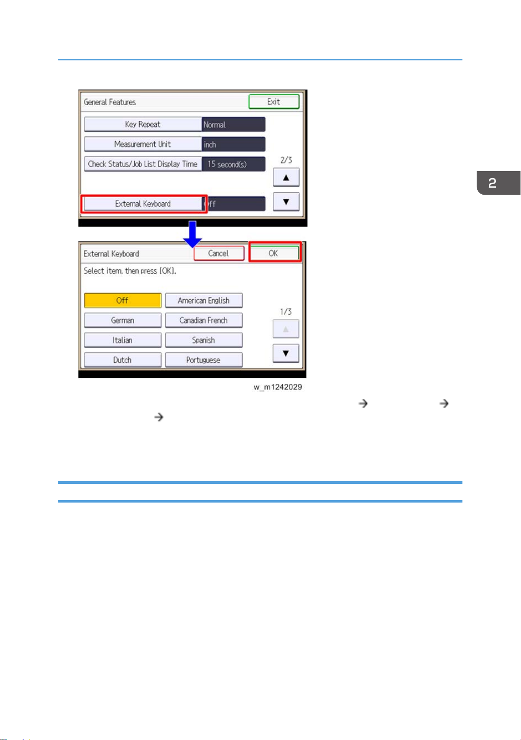
Printer Installation
4. Select a language type for the external USB keyboard with [User Tools] [System Settings]
[General Features] [External Keyboard].
5. Press [OK] to set it.
6. Turn the main power off and on.
Moving the Machine
This section shows you how to manually move the machine from one floor to another floor. See the
section "Transporting the Machine" if you have to pack the machine and move it a longer distance.
• Remove all trays from the optional paper feed unit or LCT.
• Remove peripherals physically attached to the main machine: Paper feed unit, LCT and finisher.
• Attach the caster stands for the paper feed unit or LCT if these have been removed before moving
the machine.
51
Page 54

2. Installation
Transporting the Machine
1. Remove the toner cartridges. This prevents toner flow into the toner supply tube, which is caused by
vibration during transport. This can also cause the tube to be clogged with toner.
2. Make sure there is no paper left in the paper trays. Then fix down the bottom plates with a sheet of
paper and tape.
3. Empty the toner collection bottle. Then attach securing tape to stop the toner bottle from coming
out.
4. Do one of the following:
• Attach shipping tape to the covers and doors.
• Shrink-wrap the machine tightly.
• After you move the machine, make sure you do the "Auto Color Registration" as follows. This
optimizes color registration.
• 1. Do the "Forced Line Position Adj. Mode c" (SP2-111-3).
• 2. Then do the "Forced Line Position Adj. Mode a" (SP2-111-1).
To check if SP 2-111-1 was successful, watch the screen during the process. A message is
displayed at the end. Also, you can check the result with SP 2-194-10 to -12.
• Make sure that the side fences in the trays are correctly positioned to prevent color registration
errors.
52
Page 55

Optional Unit Combinations
Machine Options
U: User installation, C: CE installation
No. Options Remarks
1 One-tray paper feed unit U
Optional Unit Combinations
2 Two-tray paper feed unit U
3 2000-sheet LCT U
4 1200-sheet LCT C Requires No.2 or 3
5 Bridge unit C -
6 3000-sheet finisher C One from No.6 and No.7.
7 2000-sheet booklet finisher C
8 *Punch kit (3 types) C
9 Output Jogger Unit C Requires No. 6 or No. 7.
10 Mail bin C
*: Child options (Child options require a parent option.)
• For details about installation procedures for the user installation options, see "Hardware Guide" of
this model.
One from No.1, No.2, No.3
Requires No.5 and one from No.2 and
No.3.
No.6 or No.7 required.
One of the three types
Controller Options
U: User installation, C: CE installation
53
Page 56

2. Installation
No. Options Remarks
1 IEEE 1284 U
One from No.1 and No.2
2 Wireless LAN U
3 Gigabit Ethernet U Gigabit Ethernet Slot
4 HDD U Option only for M124
5 PictBridge U
6 IPDS Unit U
You can merge all applications in one SD
card with SP mode. (
p.97 "SD Card
Appli Move").
7 SD Card for Netware Printing U
8 VM Card U
If the VM card is installed, merge
applications in VM card.
9 512MB Memory Option U
One from No.10 and No.11
10 1GB Memory Option U
• For details about installation procedures for the user installation options, see "Hardware Guide" of
this model.
54
Page 57

1200 LCT (D631)
Component Check
Check the quantity and condition of the components against the following list.
No. Description Q'ty
1 Front Bracket 1
2 Rear Bracket 1
3 Stud Screw 4
4 Joint Pin 2
5 LCT 1
1200 LCT (D631)
55
Page 58
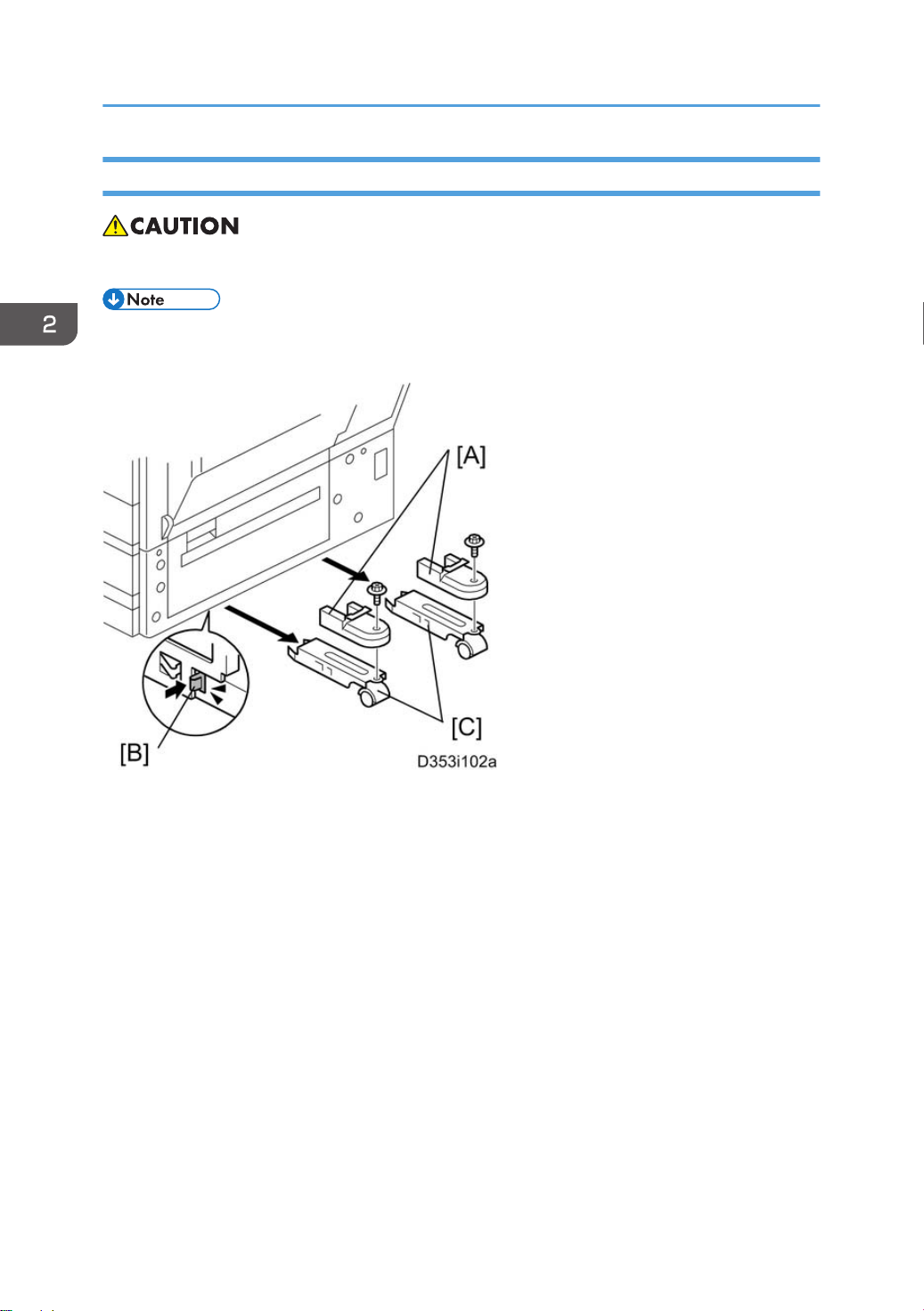
2. Installation
Installation Procedure
• Unplug the main machine power cord before starting the following procedure.
• The Paper Tray Unit (D580) or LCT 2000-sheet (D581) must be installed before installing this
1200-sheet LCT.
56
1. Unpack the LCT and remove the tapes.
2. Remove the stand covers [A].
3. Release the locks [B] of the front and rear caster stands.
4. Remove the caster stands [C].
Page 59
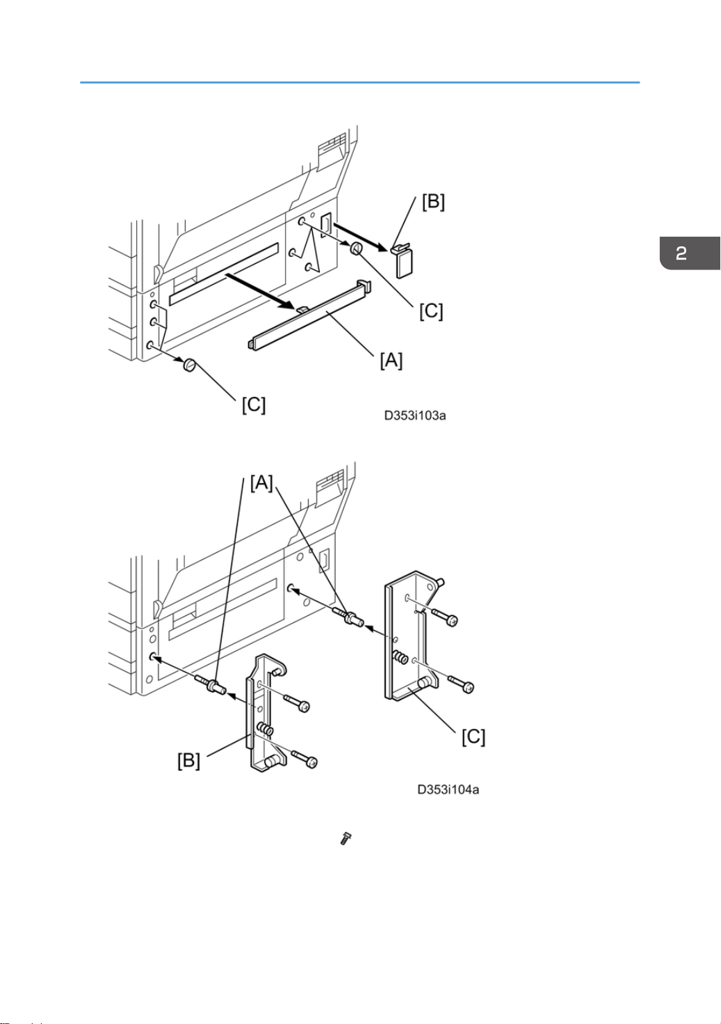
5. Remove the paper path cover [A], connector cover [B] and six hole covers [C].
1200 LCT (D631)
6. Insert the joint pins [A].
7. Attach the front [B] and rear brackets [C]. ( x 2 each)
57
Page 60

2. Installation
8. Pull out the front and rear rails [A], and then hang them on each bracket [B].
9. Connect the LCT cable [C] to the main machine.
10. Slide the LCT [D] into the main machine.
11. Make sure that the front and rear sides of the LCT are closely attached to the main machine.
Side Fence Position Change
1. Open the right door of the LCT.
2. Push the down switch to lower the tray bottom plate until it reaches its lowest position.
58
Page 61

3. Remove the front and rear side fences [A, B] ( x 1 each).
4. Install the side fences in the correct position (A4 LEF/ LT LEF/ B5 LEF).
1200 LCT (D631)
5. Pull the end fence [A] for B5 size paper as shown ( x 1) if the side fences are adjusted for B5 size
paper.
6. Close the right door.
7. Turn on the main power switch, and then go into the SP mode.
8. Input the correct paper size for the1200-sheet LCT with SP5181-018.
59
Page 62

2. Installation
Bridge Unit (D634)
Component Check
Check the quantity and condition of the components against the following list.
No. Description Q'ty
1 Bridge Unit 1
2 Frame Cover 1
3 Knob screw 1
4 Long Knob Screw 1
5 Holder bracket 1
6 Guide 2
Installation Procedure
• Unplug the machine power cord before starting the following procedure.
60
Page 63
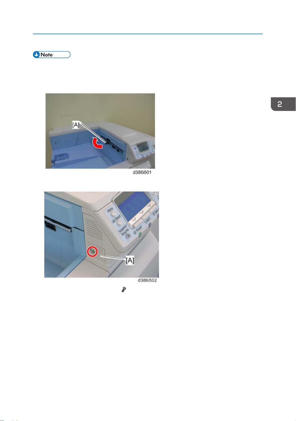
Bridge Unit (D634)
• If you will install a finisher unit (D636 or D637) on the machine, install it after installing the bridge
unit (D634).
1. Remove all tapes.
2. If the sensor feeler [A] is out, fold it into the machine.
3. Remove the connection cover [A] ( x 1).
61
Page 64

2. Installation
4. Remove the inner tray [A].
5. Remove the connector cover [B] ( x 1).
6. Install the bridge unit [A].
7. Open the bridge unit cover [B]
8. Secure it with the knob screw [C] and long knob screw [D].
9. Attach the frame cover [E].
10. Close the bridge unit cover [B].
62
Page 65

11. Reassemble the machine.
12. Install the optional finisher (refer to the finisher installation procedure).
• Holder bracket [A] is used in the installation procedure of the finisher (D636 or D637). Do not
install it yet.
Bridge Unit (D634)
13. Turn on the main power switch of the machine.
Check the bridge unit operation.
63
Page 66

2. Installation
2000-sheet booklet finisher (D637) /3000sheet finisher (D636)
Accessory Check
Check the quantity and condition of the accessories against the following list.
No. Description Q'ty
1 Rear joint bracket 1
2 Front joint bracket 1
3 Ground (earth) plate 1
4 Tapping screws - M4 x14 4
5 Tapping screws - M3 x 8 1
6 Tapping screws - M3 x 6 2
7 Upper output tray 1
8 Support Tray 1
9 Lower output tray (D637 only) 1
10 Cushion (with double-sided tape) 1
64
Page 67

2000-sheet booklet finisher (D637) /3000-sheet finisher (D636)
Installation Procedure
• Unplug the main machine power cord before starting the following procedure.
If this finisher is installed on this machine, the following options must be installed before installing this
finisher.
• Bridge Unit (D634)
• Two Tray Paper Feed Unit (D580) or LCT (D581)
65
Page 68

2. Installation
1. Unpack the finisher and remove all tapes and packing materials from the finisher.
2. Open the front door, and then remove all tapes and packing materials from the inside of the
finisher.
66
Page 69

2000-sheet booklet finisher (D637) /3000-sheet finisher (D636)
3. Pull out the jogger unit [A], and then remove all tapes and retainers.
4. Attach the cushion [B] to the finisher.
• Make sure that the cushion is placed within 0 to 1 mm from the edge of the cover.
5. Install the ground plate [C] on the finisher ( x 2; M3 x 6).
67
Page 70

2. Installation
6. Attach the rear joint bracket [D] ( x 2; M4 x 14).
7. Attach the front joint bracket [E] and the holder bracket [F] ( x 2; M4 x 14).
• Holder bracket [F] must be placed outside the front joint bracket [E]. This bracket is provided
with the Bridge Unit (D634).
8. Pull the lock lever [G] ( x 1).
9. Slowly push the finisher to the left side of the machine, keeping its front door open until the brackets
[D] [E] go into their slots.
10. Push the lock lever [G], and then secure it ( x 1).
11. Close the front door of the finisher.
68
Page 71

2000-sheet booklet finisher (D637) /3000-sheet finisher (D636)
12. Connect the finisher connector [H] to the machine.
13. Install the upper output tray [I] ( x 1; M3 x 8).
14. Only for D637, install the lower output tray [J].
15. Turn on the main power switch of the machine.
16. Check the finisher operation.
69
Page 72

2. Installation
Support Tray Installation
If a stacking problem occurs several times on the upper output tray [A], put the support tray [B] on the
tray as shown.
• Keep this tray in the manual pocket if this tray does not need to be installed.
70
Page 73

Punch Unit (D570)
Punch Unit (D570)
The Punch Unit (D570) is installed in the 2000-Sheet Booklet (D637) Finisher/ 3000-Sheet Finisher
(D636).
Component Check
Check the quantity and condition of the components against the following list.
No. Description Q'ty
1 Punch-out Waste Unit 1
2 Slide Drive Unit 1
3 Punch Waste Hopper 1
4 Wire harness: short-circuit 1
5 Screws: M3 x 6 5
6 Side-to-Side Detection Unit 1
7 Punching Unit 1
71
Page 74
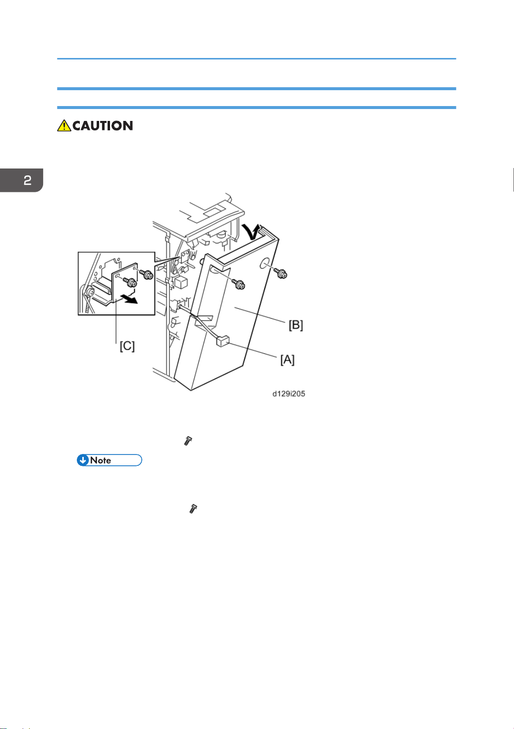
2. Installation
Installation Procedure
• Unplug the main machine power cord before starting the following procedure. If the 2000-sheet
booklet/ 3000-sheet finisher has been installed, disconnect it and pull it away from the machine.
1. Remove all tapes and shipping retainers.
72
2. If the finisher is connected to the machine, disconnect the power connector [A] and separate the
finisher from the machine.
3. Remove the rear cover [B] ( x 2) and open the front door.
• At the bottom of the rear cover, make sure to disconnect the tabs that attach the cover to the
frame.
4. Remove the guide plate [C] ( x 2).
Page 75

5. Remove the shipping retainer [A] from the punch unit ( x 2).
Punch Unit (D570)
6. Move the punch unit [A] along its rails into the finisher. Make sure that the pin engages correctly at
the front and rear.
7. Connect the cables [B] of the finisher to the connectors (CN601 and CN602) on the punch unit
board ( x 2, x 1).
• The cables [B] are coiled and attached to the PCB.
73
Page 76

2. Installation
8. Attach the slide drive unit [A] to the finisher and connect it to the punch unit ( x 2, x 1). Push
in the slide drive unit at when you attach the screw .
9. Make sure that the punch unit moves freely and is not blocked by the screws.
10. Put the side-to-side detection unit [A] in the machine. Make sure that the two pins are engaged
correctly at the front.
11. Make sure that the side-to-side detection unit moves smoothly on its rails. If it does not, make sure
that the rails are aligned with their grooves.
12. Attach the side-to-side detection unit and connect it at the rear ( x 2, x 1, x 1).
13. Pull the short connector out of the connector [B] then connect the cable of the finisher ( x 1).
• This is the 3-pin connector.
74
Page 77
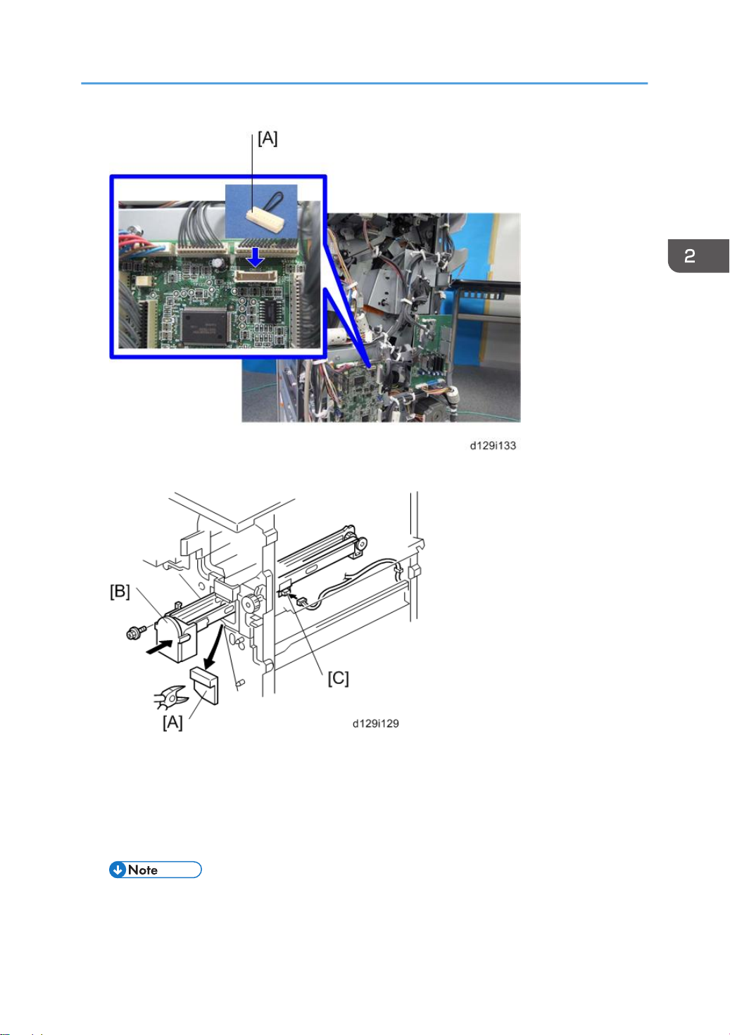
14. Connect "Wire harness: short-circuit" [A] to the CN110 connector.
Punch Unit (D570)
15. At the front, use a pair of wire cutters to remove the part [A] of the cover.
16. Install the punch-waste transport unit [B] in the finisher.
17. Make sure that the punch-waste transport unit moves smoothly on its rails. If it does not, make sure
that the rails are aligned with the grooves.
18. Remove the short connector from the connector [C].
• This is the 4-pin connector.
75
Page 78

2. Installation
19. Connect the cable to connector [C] and attach the punch-waste transport unit ( x 1, x 1,
x 1).
20. Set the hopper [A] in its holder.
21. Reassemble the finisher, and then install it on the main machine.
22. Connect the power cord to the outlet, and then turn the main power switch on.
23. Check the punch unit operation.
76
Page 79

Output Jogger Unit (B703)
Accessories
Check the accessories and their quantities against this list.
No. Description Q'ty
1 Jogger Unit 1
2 Tapping Screws M3x6 2
Output Jogger Unit (B703)
Installation
The Output Jogger Unit B703 is installed only on the 3000-Sheet Finisher (D636) and 2000-sheet
Booklet Finisher (D637).
• Always switch the machine off and unplug the machine before doing any of the following
procedures
1. Turn the main machine switch off.
2. Disconnect the finisher from the main frame.
77
Page 80

2. Installation
3. Use the flat head of a screwdriver to remove the left upper cover [A].
78
4. Remove the cover plate [A] ( x 2). Keep the screws.
Page 81
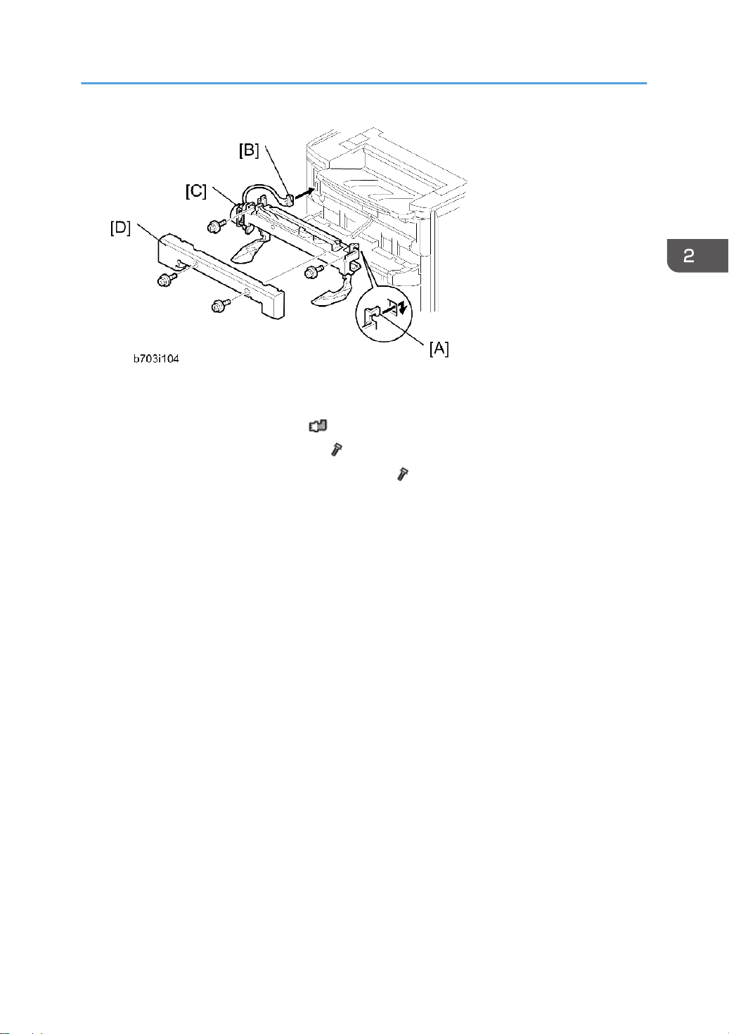
Output Jogger Unit (B703)
5. While holding the jogger unit with the connector on the left, put the hooks on the frame of the
jogger unit [A] into the holes in the left and right side of the finisher frame.
6. Connect connector [B] to the socket ( x 1).
7. Attach the jogger unit [C] to the finisher ( x 2).
8. Reattach the jogger unit cover [D] to the jogger unit ( x 2).
79
Page 82

2. Installation
Mail Bin (M413)
Component Check
Check the quantity and condition of the components against the following list.
No. Description Q'ty
1 Tray 4
2 Rear Hold Bracket 1
3 Front Hold Bracket 1
4 Mail Bin 1
5 Right Stay 1
6 Guide Plate 1
7 Mail Bin Solenoid 1
8 Harness 1
9 Clamp (Not used) 1
10 Screw: M3x8 2
11 Screw: M4x10 3
12 Screw: M3x6 7
13 Step Screw 2
- Decal Sheet 1
80
Page 83

Mail Bin (M413)
Installation Procedure
1. Open the right door.
81
Page 84

2. Installation
82
2. Operation panel [A] ( x 2, x 1, x 2, USB x 1)
Page 85

3. Remove the following:
• Screw caps [A]
• Top right cover [B] ( x 2)
• Top rear cover [C] ( x 2)
Mail Bin (M413)
4. Remove the paper exit cover [A] ( x 1).
5. Remove the top right stay [B] ( x 3).
83
Page 86

2. Installation
6. Install the mail bin solenoid [A] ( x 1: M3x8).
7. Connect the harness [B] and then clamp the harness with the four clamps.
8. Reinstall the top right stay [A] ( x 3).
9. Install the guide plate [B] ( x 2: M3x6).
10. Install the paper exit cover [C] ( x1).
11. Install the two step screws [D].
12. Remove the rear cover [A] ( x1).
13. Remove the top cover [B] of the mail bin unit.
14. Remove the front cover [C] ( x1).
84
Page 87

Mail Bin (M413)
• The front cover is connected to the mail bin unit with the harnesses. It is not necessary to
disconnect the harnesses from the front cover. However, take care not to break or disconnect
the harnesses during this installation procedure.
15. Install the mail bin unit [A] on the machine as shown above.
16. Attach the front hold bracket [A] and rear hold bracket [B] ( x 2 each).
85
Page 88

2. Installation
17. Release the harness [A] from the machine ( x 1).
18. Connect the harness [A] to the main board of the mail bin unit ( x 1).
19. Reinstall the top rear cover ( x 2)
20. Install the right stay [A] ( x 1).
21. Reinstall the top, front and rear covers of the mail bin unit ( x 2).
22. Reinstall the operation panel and connection cover ( x 2).
23. Close the right door.
86
Page 89

24. Install the tray [A] in each bin of the mail bin unit [B].
25. Plug in and turn on the machine.
26. Check the operation of the mail bin unit.
Mail Bin (M413)
87
Page 90
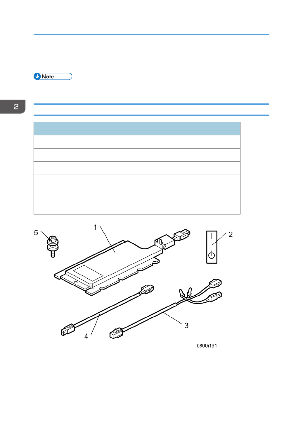
2. Installation
Anti-Condensation Heater
• This option is provided as a service part.
Component Check
No. Description Q'ty
1 Tray heater 1
2 On-standby decal 1 (-90) or 2 (-91)
3 Harness 2 (For D579) 1
4 Harness 1 (For D580/D581) 1
5 Screw M4 x 10 2
- Installation procedure 1
88
Page 91

Installation Procedure
• Unplug the machine power cord before starting the following procedure.
• Do the following procedure not to damage any harnesses.
• Check that any harnesses are not damaged nor pinched after installation.
For installing the tray heater in the main machine
Anti-Condensation Heater
1. Remove trays 1 and 2 from the machine.
2. Remove the connector cover [A] ( x 1).
3. Connect the connector [B] of the heater to the connector of the main machine.
4. Install the heater [C] inside the machine ( x 1)
5. Reassemble the machine.
89
Page 92

2. Installation
For installing the tray heater in D580
1. Rear cover [A] ( x 6)
2. Pull out the two trays in the optional paper feed unit.
3. Install the tray heater [B] in the optional paper feed unit ( x 1).
90
Page 93

Anti-Condensation Heater
4. Remove the two securing brackets [C] ( x 1 each), and then the rear cover [D] of the optional
paper feed unit ( x 2).
5. Remove the harness cover bracket [E] ( x 1).
6. Pull out tray 2 from the mainframe.
7. Replace the shoulder screw [F] with the washer screw [G], using securing bracket [H] ( x 1).
91
Page 94
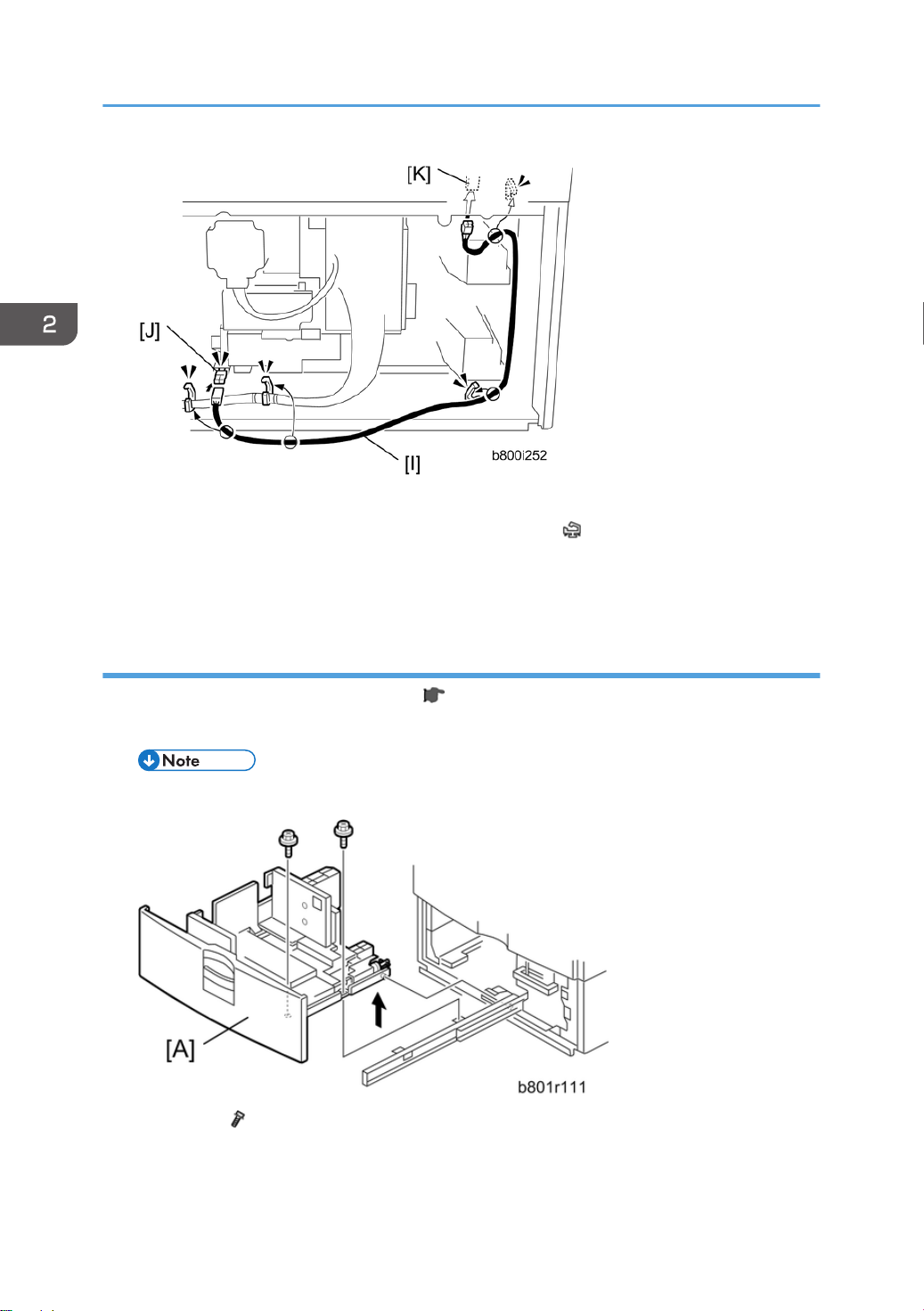
2. Installation
8. Connect the harness [I] to the connector [J] of the tray heater.
9. Route the harness [I] as shown and clamp it with four clamps ( x 4).
10. Connect the harness [I] to the connector [K] of the mainframe.
11. Reassemble the mainframe and optional paper feed unit.
For Installing the tray heater in D581
1. Remove the rear cover of the mainframe ( step 1 in "For Installing the Tray Heater in D580").
2. Pull out the LCT drawer.
• If the right tray comes out with the left tray, push the right tray into the LCT.
3. Left tray [A] ( x 2)
92
Page 95
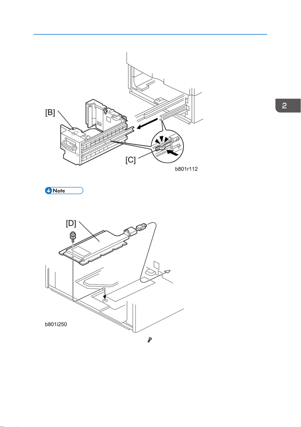
4. Remove the right tray [B] while pressing down the stopper [C].
Anti-Condensation Heater
• When reinstalling the right tray, set the right tray on the guide rail and carefully push the tray
in, making sure to keep the tray level.
5. Install the tray heater [D] in the optional LCT ( x 1).
93
Page 96

2. Installation
6. Remove the two securing brackets [E] ( x 1 each), and the then rear cover [F] of the optional
LCT ( x 2).
7. Remove the harness cover bracket [G] ( x 1).
94
8. Pull out tray 2 from the mainframe.
9. Replace the shoulder screw [7] with the washer screw [8], using the securing bracket [9] ( x 1).
Page 97

10. Connect the harness [K] to the connector [L] of the tray heater.
11. Route the harness [K] as shown and clamp it with four clamps ( x 4).
12. Connect the harness [K] to the connector [M] of the mainframe.
13. Reassemble the mainframe and optional LCT.
14. Reassemble the mainframe and optional paper feed unit.
Anti-Condensation Heater
95
Page 98

2. Installation
Controller Options
Overview
• Always touch a grounded surface to discharge static electricity from your hands before you handle
SD cards, printed circuit boards, or memory boards.
• If the VM card is installed, use the VM card as a target SD card.
This machine has I/F card slots for optional I/F connections and SD card slots applications.
After you install an option, check that the machine can recognize it (see "Check All Connections" at the
end of this section).
I/F Card Slots
SD Card Slots
96
• Slot [A] is used for one of the optional I/F connections (only one can be installed): IEEE1284 or
IEEE802.11a/g (Wireless LAN).
• Slot [B] is used for Gigabit Ethernet.
• Slot [1] (upper) is used for optional applications (e.g.: Netware, PictBridge, IPDS unit, etc).
Page 99

Controller Options
• Slot [2] (lower) is also used for installing applications, or for service only (for example, updating
the firmware).
SD Card Appli Move
Overview
The service program "SD Card Appli Move" (SP5-873) lets you move application programs from one
SD card to another SD card.
If more than one application is required, the applications must be moved to one SD card with SP5873-1
(Security Application, PictBridge, IPDS unit, etc.).
Be very careful when you do the SD Card Appli Move procedure:
• The data necessary for authentication is transferred with the application program from an SD card
to another SD card. Authentication fails if you try to use the SD card after you move the application
program from one card to another card.
• Do not use the SD card if it has been used before for other purposes. Normal operation is not
guaranteed when such an SD card is used.
• Remove the cover [A] ( x 2), and then keep the SD card in the place [B] after you move the
application program from one card to another card. This is done for the following reasons:
• The SD card can be the only proof that the user is licensed to use the application program.
• You may need to check the SD card and its data to solve a problem in the future.
97
Page 100

2. Installation
Move Exec
The menu "Move Exec" (SP5-873-001) lets you move application programs from the original SD card
to another SD card.
• Do not turn ON the write protect switch of the system SD card or application SD card on the
machine. If the write protect switch is ON, a download error (e.g. Error Code 44) occurs during a
firmware upgrade or application merge.
1. Turn the main switch off.
2. Make sure that a target SD card is in SD Card Slot 1 (upper). The application program is moved to
this SD card.
3. Insert the source SD card with the application program in SD Card Slot 2 (lower).The application
program is copied from this source SD card.
4. Turn the main switch on.
5. Start the SP mode.
6. Select SP5-873-001 "Move Exec".
7. Follow the messages shown on the operation panel.
8. Turn the main switch off.
9. Remove the source SD card from SD Card Slot 2 (lower).
10. Turn the main switch on.
11. Check that the application programs run normally.
Undo Exec
"Undo Exec" (SP5-873-002) lets you move back application programs from an SD card in SD Card
Slot 1 (upper) to the original SD card in SD Card Slot 2 (lower). You can use this program when, for
example, you have mistakenly copied some programs by using Move Exec (SP5-873-001).
• Do not turn ON the write protect switch of the system SD card or application SD card on the
machine. If the write protect switch is ON, a download error (e.g. Error Code 44) occurs during a
firmware upgrade or application merge.
1. Turn the main switch off.
2. Insert the original SD card in SD Card Slot 2 (lower). The application program is copied back into
this card.
3. Insert the SD card with the application program in SD Card Slot 1 (upper).The application program
is copied back from this SD card.
98
4. Turn the main switch on.
 Loading...