

Page 1
Operating Instructions
General Settings Guide
Connecting the Machine
1
System Settings
2
Copier/Document Server Features
3
Printer Features
4
Scanner Features
5
Registering Addresses and Users for Scanner Functions
6
Other User Tools
7
Appendix
8
Read this manual carefully before you use this machine and keep it handy for future reference. For safe and correct use, be sure to read the
Safety Information in "About This Machine" before using the machine.
Page 2

Introduction
This manual contains detailed instructions and notes on the operation and use of this machine. For your
safety and benefit, read this manual carefully before using the machine. Keep this manual in a handy
place for quick reference.
Important
Contents of this manual are subject to change without prior notice. In no event will the company be liable for direct, indirect, special, incidental, or consequential damages as a result of handling or operating the machine.
Notes:
Some illustrations in this manual might be slightly different from the machine.
Certain options might not be available in some countries. For details, please contact your local dealer.
Notes:
The model names of the machines do not appear in the following pages. Check the type of your machine before reading this manual.
• Type 1: 8055/DSm755/LD255/Aficio MP 5500
• Type 2: 8065/DSm765/LD265/Aficio MP 6500
• Type 3: 8075/DSm775/LD275/Aficio MP 7500
Certain types might not be available in some countries. For details, please contact your local dealer.
Two kinds of size notation are employed in this manual. With this machine refer to the inch version.
Page 3

Manuals for This Machine
Refer to the manuals that are relevant to what you want to do with the machine.
❖ About This Machine
Be sure to read the Safety Information in this manual before using the machine.
This manual provides an introduction to the functions of the machine. It also
explains the control panel, preparation procedures for using the machine,
how to enter text, and how to install the CD-ROMs provided.
❖ General Settings Guide
Explains User Tools settings, and Address Book procedures such as registering e-mail addresses, and user codes. Also refer to this manual for explanations on how to connect the machine.
❖ Troubleshooting
Provides a guide to solving common problems, and explains how to replace
paper, toner, staples, and other consumables.
❖ Security Reference
This manual is for administrators of the machine. It explains security functions that the administrators can use to protect data from being tampered, or
prevent the machine from unauthorized use.
Also refer to this manual for the procedures for registering administrators, as
well as setting user and administrator authentication.
❖ Copy/ Document Server Reference
Explains Copier and Document Server functions and operations. Also refer to
this manual for explanations on how to place originals.
❖ Printer Reference
Explains Printer functions and operations.
❖ Scanner Reference
Explains Scanner functions and operations.
❖ Network Guide
Explains how to configure and operate the machine in a network environment, and use the software provided.
This manual covers all models, and includes descriptions of functions and
settings that might not be available on this machine. Images, illustrations, and
information about operating systems that are supported might also differ
slightly from those of this machine.
i
Page 4

❖ Other manuals
• PostScript3 Supplement
•UNIX Supplement
• Manuals for DeskTopBinder Lite
• DeskTopBinder Lite Setup Guide
• DeskTopBinder Introduction Guide
•Auto Document Link Guide
Note
❒ Manuals provided are specific to machine types.
❒ Adobe Acrobat Reader/Adobe Reader must be installed in order to view the
manuals as PDF files.
❒ For "UNIX Supplement", please visit our Web site or consult an authorized
dealer.
❒ "PostScript3 Supplement" and "UNIX Supplement" include descriptions of
functions and settings that might not be available on this machine.
ii
Page 5

TABLE OF CONTENTS
Manuals for This Machine ......................................................................................i
How to Read This Manual ..................................................................................... 1
Symbols ..................................................................................................................... 1
Display panel..........................................................................................................2
Accessing User Tools (System Settings)............................................................3
Changing Default Settings ......................................................................................... 3
Quitting User Tools ....................................................................................................4
About Menu Protect ...................................................................................................4
1. Connecting the Machine
Connecting to the Interfaces ................................................................................ 5
Connecting to the Ethernet Interface .........................................................................6
Connecting to the USB Interface................................................................................ 8
Connecting to the IEEE 1394 Interface......................................................................9
Connecting to the IEEE 1284 Interface......................................................................9
Connecting to the IEEE 802.11b (Wireless LAN) Interface......................................10
Network Settings..................................................................................................14
Settings Required to Use the Printer........................................................................14
Settings Required to Use E-mail Function ...............................................................17
Settings Required to Use Scan to Folder Function..................................................21
Settings Required to Use the Network Delivery Scanner.........................................24
Settings Required to Use Network TWAIN Scanner ................................................ 27
Settings Required to Use Document Server ............................................................30
Using Utilities to Make Settings................................................................................ 33
2. System Settings
General Features..................................................................................................41
Output tray settings ..................................................................................................45
Tray Paper Settings .............................................................................................46
Timer Settings ......................................................................................................52
Interface Settings.................................................................................................55
Network ....................................................................................................................55
Parallel Interface ......................................................................................................59
IEEE 1394 ................................................................................................................60
IEEE 802.11b ........................................................................................................... 62
Print List ................................................................................................................... 64
File Transfer .........................................................................................................65
Administrator Tools.............................................................................................71
Program / Change / Delete LDAP Server ................................................................80
Programming the LDAP server ................................................................................81
System Settings on Main and Sub-machines ................................................... 86
General Features .....................................................................................................86
Tray Paper Settings ................................................................................................. 88
Timer Settings .......................................................................................................... 89
Administrator Tools ..................................................................................................90
iii
Page 6

3. Copier/Document Server Features
General Features..................................................................................................95
Reproduction Ratio............................................................................................102
Edit ......................................................................................................................106
Stamp .................................................................................................................. 111
Background Numbering .........................................................................................111
Preset Stamp .........................................................................................................112
User Stamp ............................................................................................................114
Date Stamp ............................................................................................................116
Page Numbering ....................................................................................................117
Stamp Text.............................................................................................................120
Input/Output .......................................................................................................122
Settings for the Document Server....................................................................125
Copier/Document Server Features on Main and Sub-machines ................... 127
General Features ................................................................................................... 127
Reproduction Ratio ................................................................................................ 129
Edit .........................................................................................................................129
Stamp..................................................................................................................... 132
Input/Output ...........................................................................................................135
4. Printer Features
List/Test Print .....................................................................................................137
Printing the configuration page ..............................................................................138
Interpreting the configuration page ........................................................................138
Maintenance .......................................................................................................140
System ................................................................................................................141
Host Interface ..................................................................................................... 147
PCL Menu ........................................................................................................... 148
PS Menu..............................................................................................................150
PDF Menu ........................................................................................................... 151
5. Scanner Features
General Settings ................................................................................................ 153
Scan Settings .....................................................................................................155
Send Settings .....................................................................................................157
6. Registering Addresses and Users for Scanner Functions
Address Book.....................................................................................................159
Managing names in the Address Book ..................................................................161
Sending e-mail by Quick Dial .................................................................................162
Sending scanned files to a shared folder directly................................................... 162
Preventing unauthorized user access to shared folders from the machine ...........162
Managing users and machine usage ..................................................................... 162
Registering Names ............................................................................................ 163
Registering Names.................................................................................................163
Changing a Registered Name................................................................................165
Deleting a Registered Name ..................................................................................166
iv
Page 7

Authentication Information ...............................................................................167
Registering a User Code........................................................................................168
Changing a User Code...........................................................................................169
Deleting a User Code.............................................................................................171
Displaying the Counter for Each User....................................................................172
Printing the Counter for Each User ........................................................................173
Printing the Counter for All User ............................................................................174
Clearing the Number of Prints................................................................................175
E-mail Destination..............................................................................................177
Registering an E-mail Destination..........................................................................177
Changing an E-mail Destination.............................................................................179
Deleting an E-mail Destination............................................................................... 180
Registering Folders ...........................................................................................181
Using SMB to Connect...........................................................................................181
Using FTP to Connect............................................................................................188
Using NCP to Connect ...........................................................................................193
Registering Names to a Group .........................................................................199
Registering a Group ...............................................................................................199
Registering Names to a Group...............................................................................201
Adding a Groupe to Another Group .......................................................................202
Displaying Names Registered in a Group .............................................................. 203
Removing a Name from a Group ...........................................................................204
Deleting a Group Within Atnother Group ............................................................... 205
Changing a Group Name .......................................................................................207
Deleting a Goup .....................................................................................................208
Registering a Protection Code ......................................................................... 209
Registering a Protection Code to a Single User.....................................................209
Registering a Protection Code to a Group User.....................................................211
Registering SMTP and LDAP Authentication..................................................212
SMTP Authentication .............................................................................................212
LDAP Authentication ..............................................................................................214
7. Other User Tools
Changing the Display Language ......................................................................217
Inquiry .................................................................................................................218
Counter ...............................................................................................................220
Displaying the Total Counter..................................................................................220
8. Appendix
Specifications for the Main Unit .......................................................................221
Document Server ...................................................................................................225
Auto Document Feeder ..........................................................................................226
v
Page 8

Specifications for Options ................................................................................227
Mailbox................................................................................................................... 227
Booklet Finisher ..................................................................................................... 228
3,000Sheet-50Sheet Staple Finisher .....................................................................231
3,000Sheet-100Sheet Staple Finisher ...................................................................233
Punch Unit (Booklet Finisher, 3,000Sheet-50Sheet Staple Finisher) ....................235
Punch Unit (3,000Sheet-100Sheet Staple Finisher) .............................................. 236
Z-folding unit ..........................................................................................................237
Copy tray................................................................................................................237
Large Capacity Tray (LCT)..................................................................................... 238
Interposer ............................................................................................................... 238
Specifications for Others ..................................................................................239
Information about Installed Software...............................................................240
expat ......................................................................................................................240
NetBSD ..................................................................................................................240
Sablotron................................................................................................................242
JPEG LIBRARY .....................................................................................................243
SASL ......................................................................................................................243
MD4........................................................................................................................ 244
MD5........................................................................................................................ 244
Samba(Ver 3.0.4)...................................................................................................245
®
RSA BSAFE
Open SSL...............................................................................................................246
Open SSH .............................................................................................................. 248
Open LDAP ............................................................................................................253
.........................................................................................................245
INDEX....................................................................................................... 255
vi
Page 9
How to Read This Manual
Symbols
This manual uses the following symbols:
Indicates important safety notes.
Ignoring these notes could result in serious injury or death. Be sure to read these
notes. They can be found in the "Safety Information" section of About This Machine.
Indicates important safety notes.
Ignoring these notes could result in moderate or minor injury, or damage to the
machine or to property. Be sure to read these notes. They can be found in the
"Safety Information" section of About This Machine.
Indicates points to pay attention to when using the machine, and explanations
of likely causes of paper misfeeds, damage to originals, or loss of data. Be sure
to read these explanations.
Indicates supplementary explanations of the machine’s functions, and instructions on resolving user errors.
This symbol is located at the end of sections. It indicates where you can find further relevant information.
[ ]
Indicates the names of keys that appear on the machine’s display panel.
{ }
Indicates the names of keys on the machine’s control panel.
1
Page 10
Display panel
The display panel shows machine status, error messages, and function menus.
The function items displayed serve as selector keys. You can select or specify an
item by lightly pressing them.
When you select or specify an item on the display panel, it is highlighted like
. Keys appearing as cannot be used.
Important
❒ A force or impact of more than 30 N (about 3 kgf) will damage the display
panel.
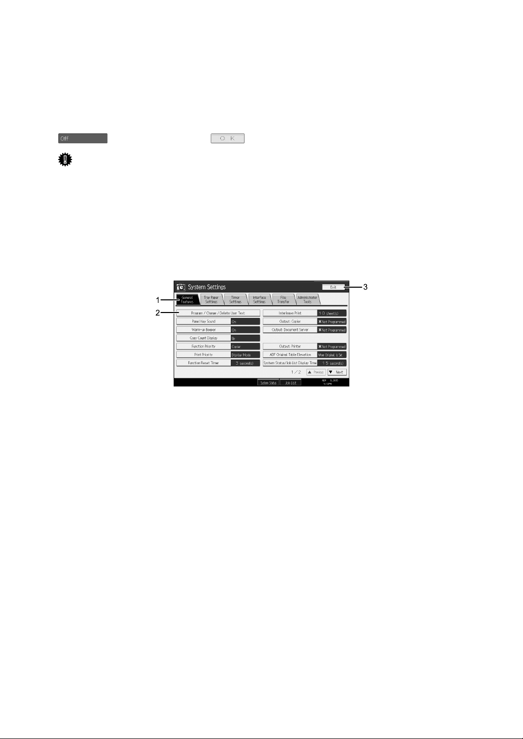
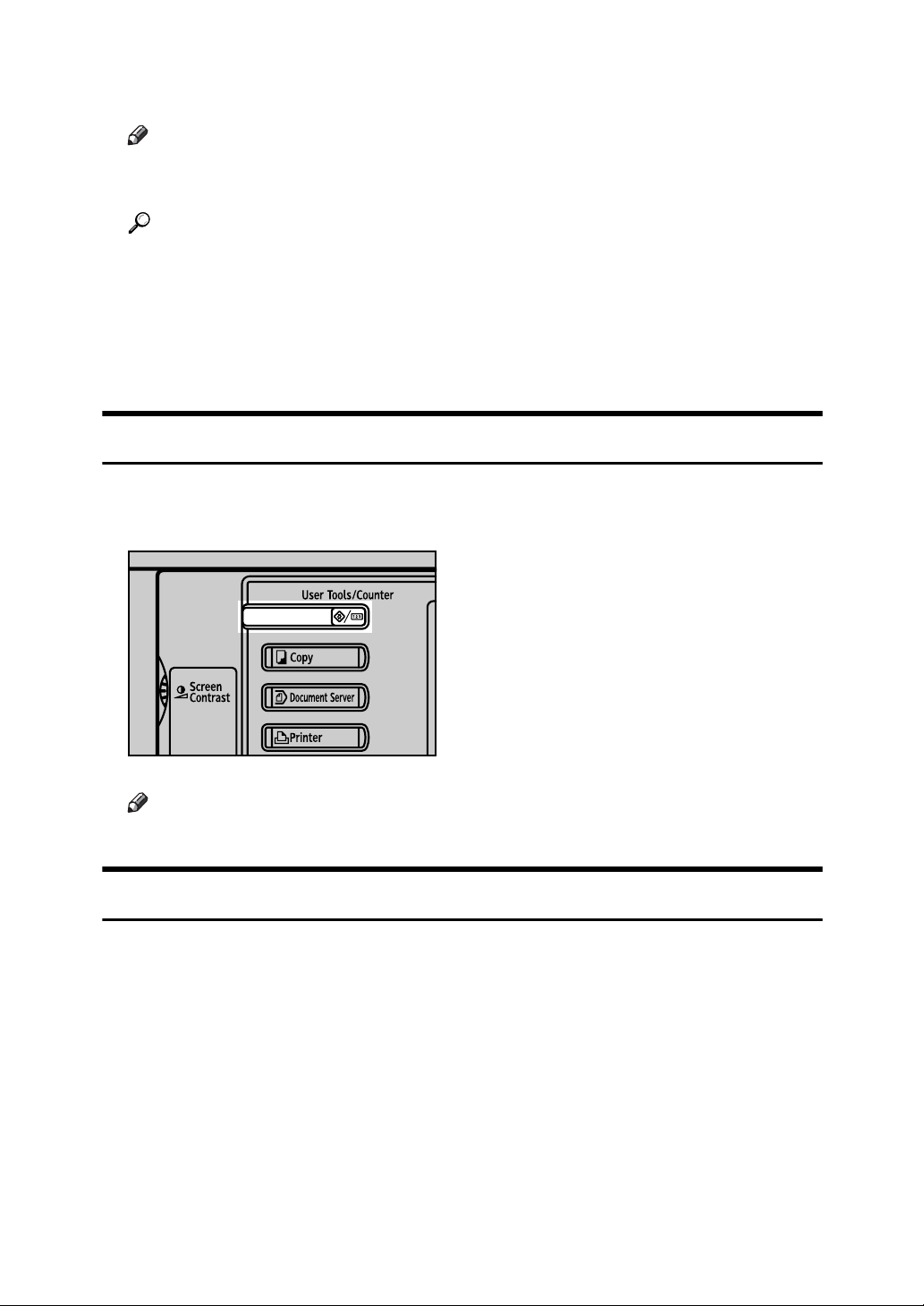
To display the following screen, press the {User Tools/Counter} key to display the
User Tools menu, and then press [System Settings].
Using the System Settings menu screen as an example, this section explains how
to use the machine’s control panel.
1. The menu tabs for various set-
tings appear. To display the setting
you want to specify or change, press
the appropriate menu tab.
2. A list of settings appears. To dis-
play the setting you want to specify
or change, select the appropriate entry in the list.
AMC001S
3. Press this to close the User Tools
menu.
2
Page 11
Accessing User Tools (System Settings)
This section is for Administrators in charge of this machine.
User Tools allow you to change or set defaults.
Note
❒ Operations for system settings differ from normal operations. Always quit
User Tools when you have finished.
❒ Any changes you make with User Tools remain in effect even if the main
power switch or operation switch is turned off, or the {Energy Saver} or {Clear
Modes} key is pressed.
Reference
p.4 “Quitting User Tools”
Changing Default Settings
This section describes how to change the settings of User Tools.
Important
❒ If the Administrator Authentications specified, contact your administrator.
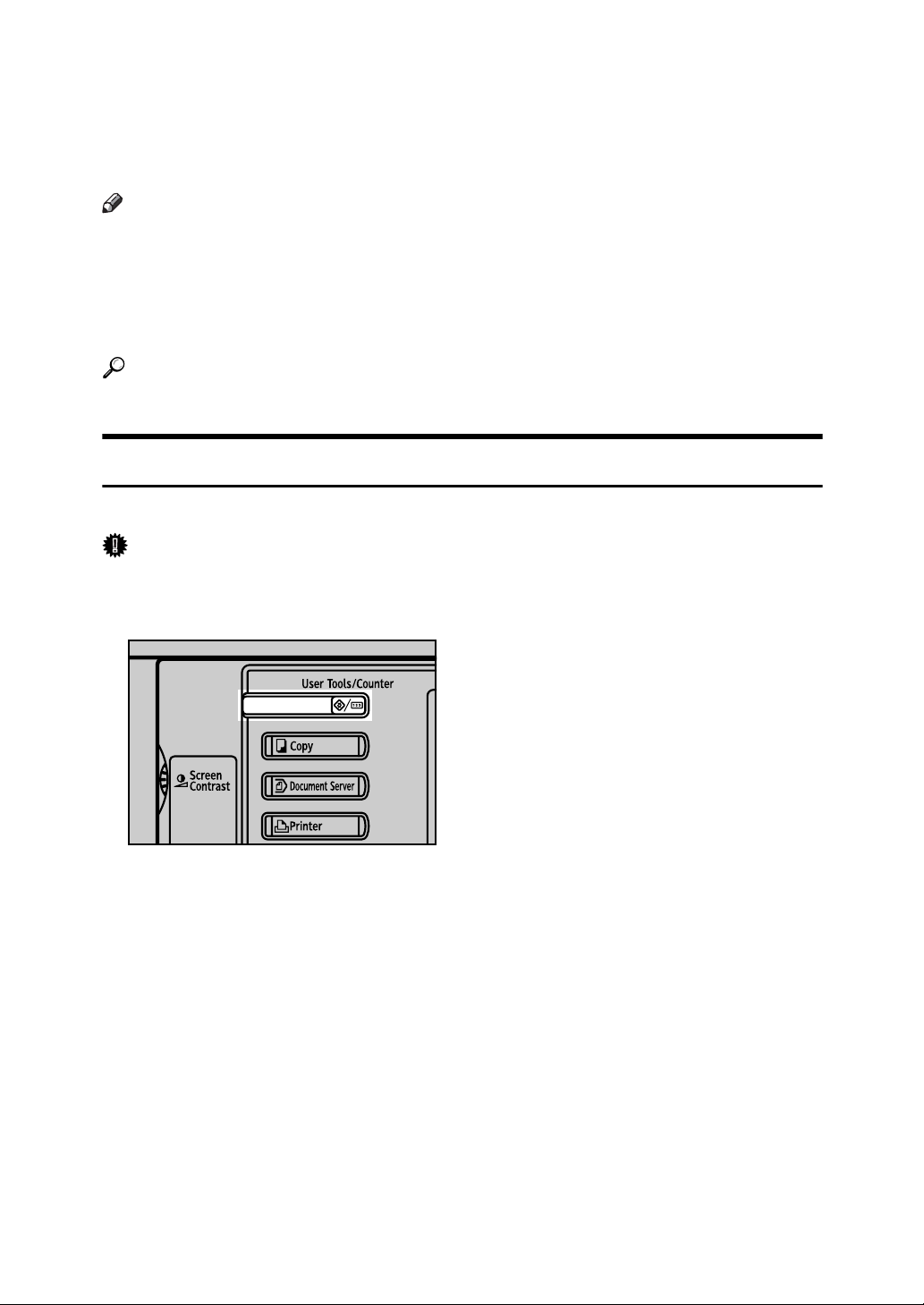
A Press the {User Tools/Counter} key.
AMN001S
B Select the menu.
To change the System Settings, Press [System Settings].
To change the Copier/Document Server Features, Press [Copier / Document
Server Features].
To change the Printer Features, Press [Printer Features].
To change the Scanner Features, Press [Scanner Features].
To change the displayed language, press [Français] or [English].
To find out who to contact for maintenance and where to order consumables,
press [Inquiry].
To check the counter, press [Counter].
C Select the menu tab.
3
Page 12
D Change settings by following instructions on the display, and then press
[OK].
Note
❒ To cancel changes made to settings and return to the initial display, press
the {User Tools/Counter} key.
Reference
p.41 “System Settings”
p.95 “Copier/Document Server Features”
p.137 “Printer Features”
p.153 “Scanner Features”
p.217 “Other User Tools”
Quitting User Tools
This section describes how to end User Tools.
A Press the {User Tools/Counter} key.
AMN001S
Note
❒ You can also quit User Tools by pressing [Exit].
About Menu Protect
Using Menu Protect, you can limit the settings available to users other than the
administrator. In the following User Tools menus, you can specify Menu Protect
for each setting.
• Copier/Document Server Features
•Printer Features
• Scanner Features
For details about menu protect, contact your administrator.
4
Page 13
1. Connecting the Machine
Connect the machine to the network to configure network environment.
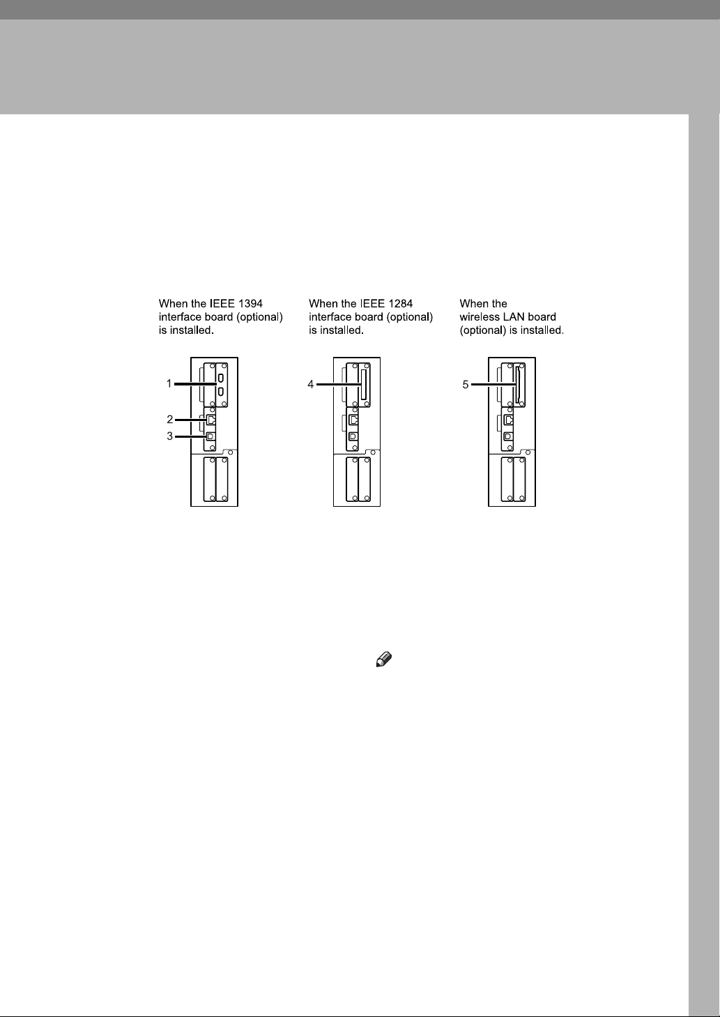
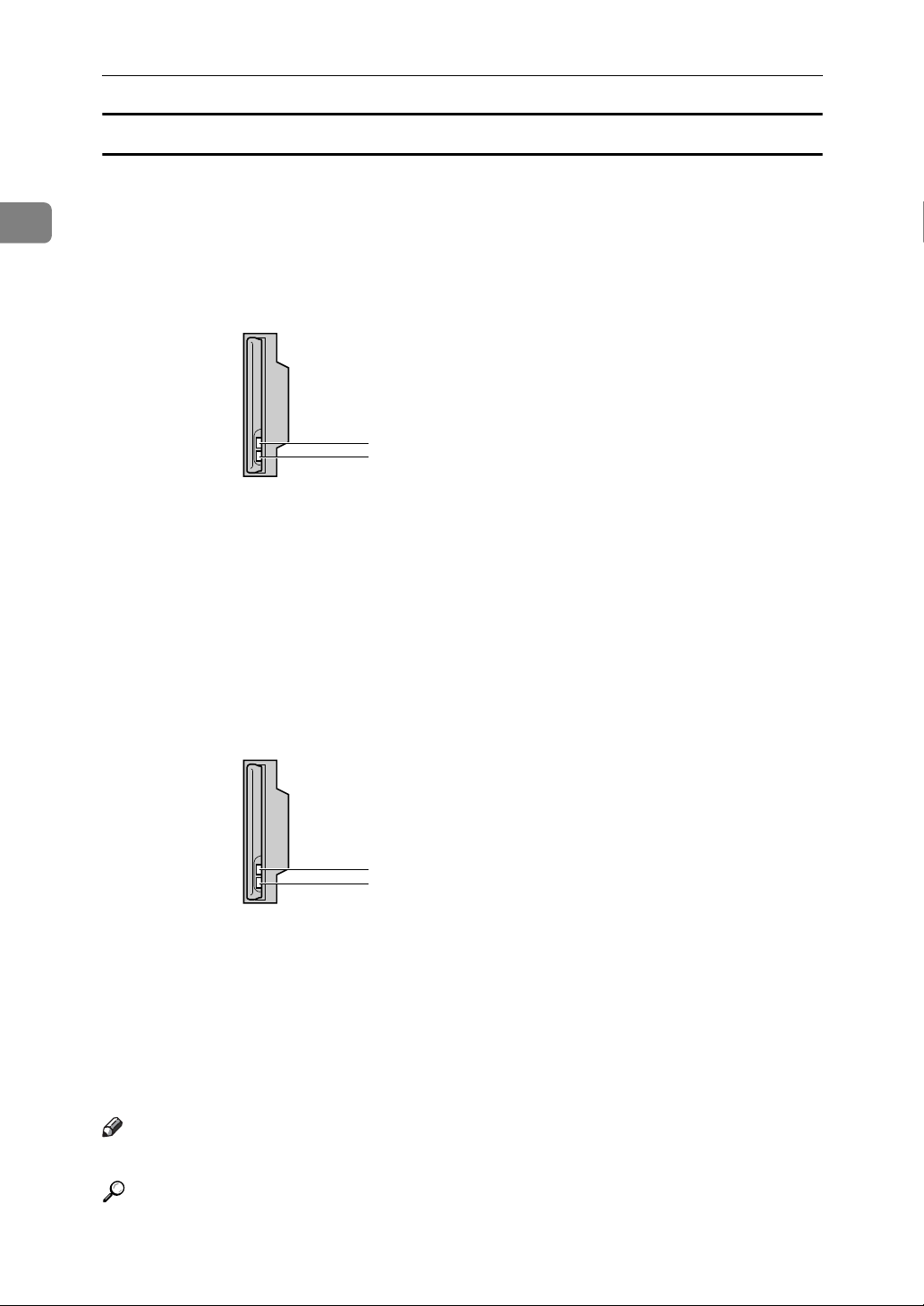
Connecting to the Interfaces
This section explains how to check the machine’s interface, connect the machine
according to the network environment, and specify the network settings.
1. IEEE 1394 ports (optional)
Ports for connecting the IEEE 1394 interface cable
2. 10BASE-T/100BASE-TX port
Port for connecting the 100BASE-TX or
10BASE-T cable
Port for connecting the 1000BASE-T,
100BASE-TX or 10BASE-T cable when
the Gigabit Ethernet (Optional) is installed
3. USB2.0 port
Port for connecting the USB2.0 interface
cable
AMC004S
4. IEEE 1284 port (optional)
Port for connecting the IEEE 1284 interface cable
5. Wireless LAN port (optional)
Port for using the wireless LAN
Note
❒ You cannnot install two or more of the
options below: IEEE 1394 interface
board, IEEE 1284 interface board,
IEEE 802.11b wireless LAN
5
Page 14
Connecting the Machine
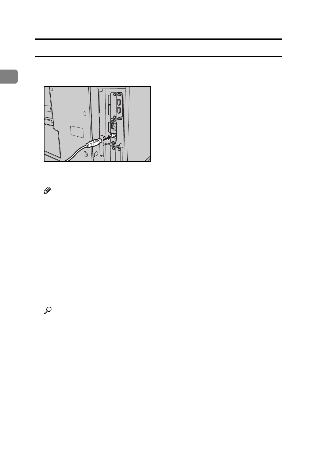
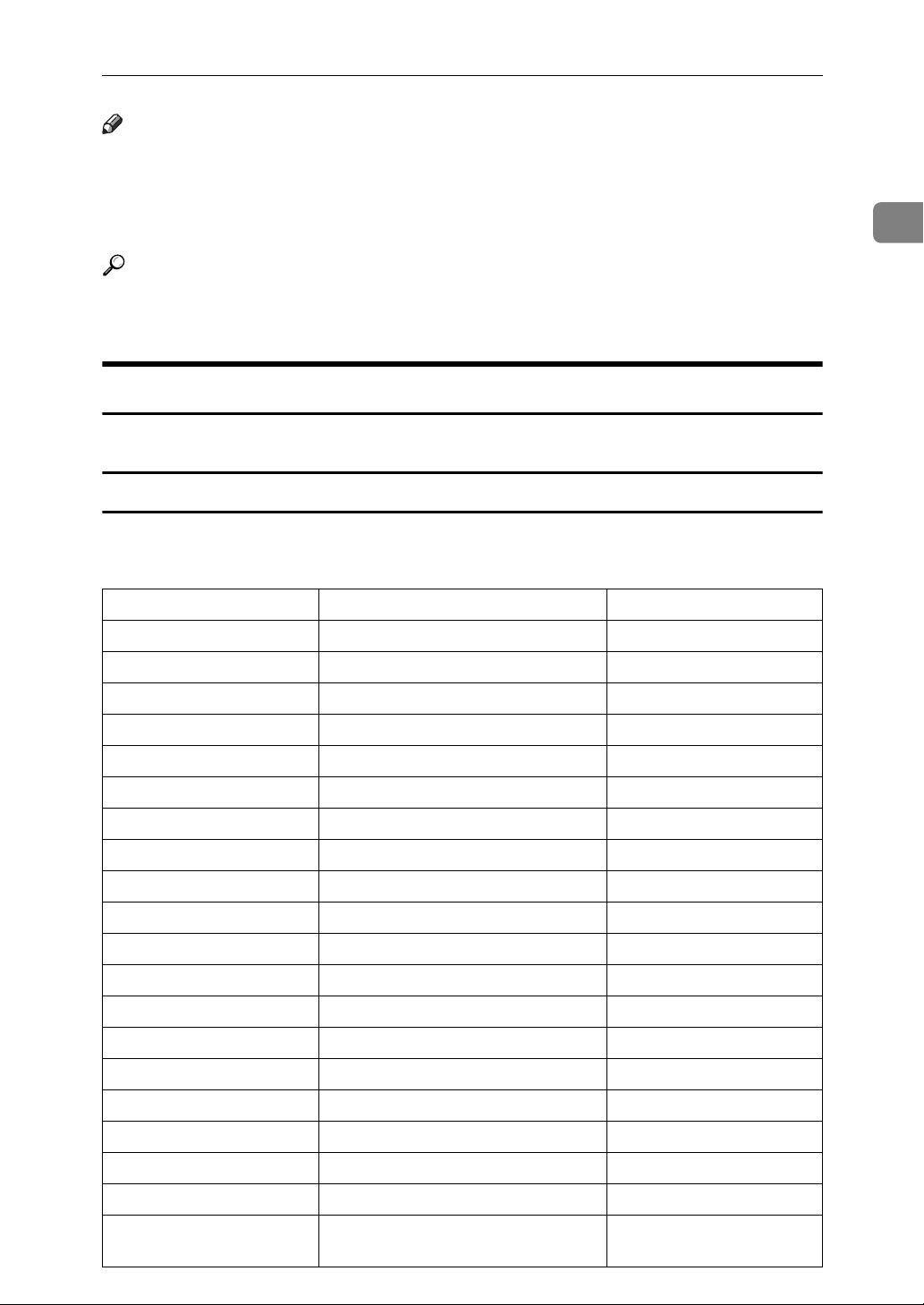
Connecting to the Ethernet Interface
Connect 10BASE-T or 100BASE-TX cable to the Ethernet interface.
1
Important
❒ If the main power switch is turned "On", turn it "Off".
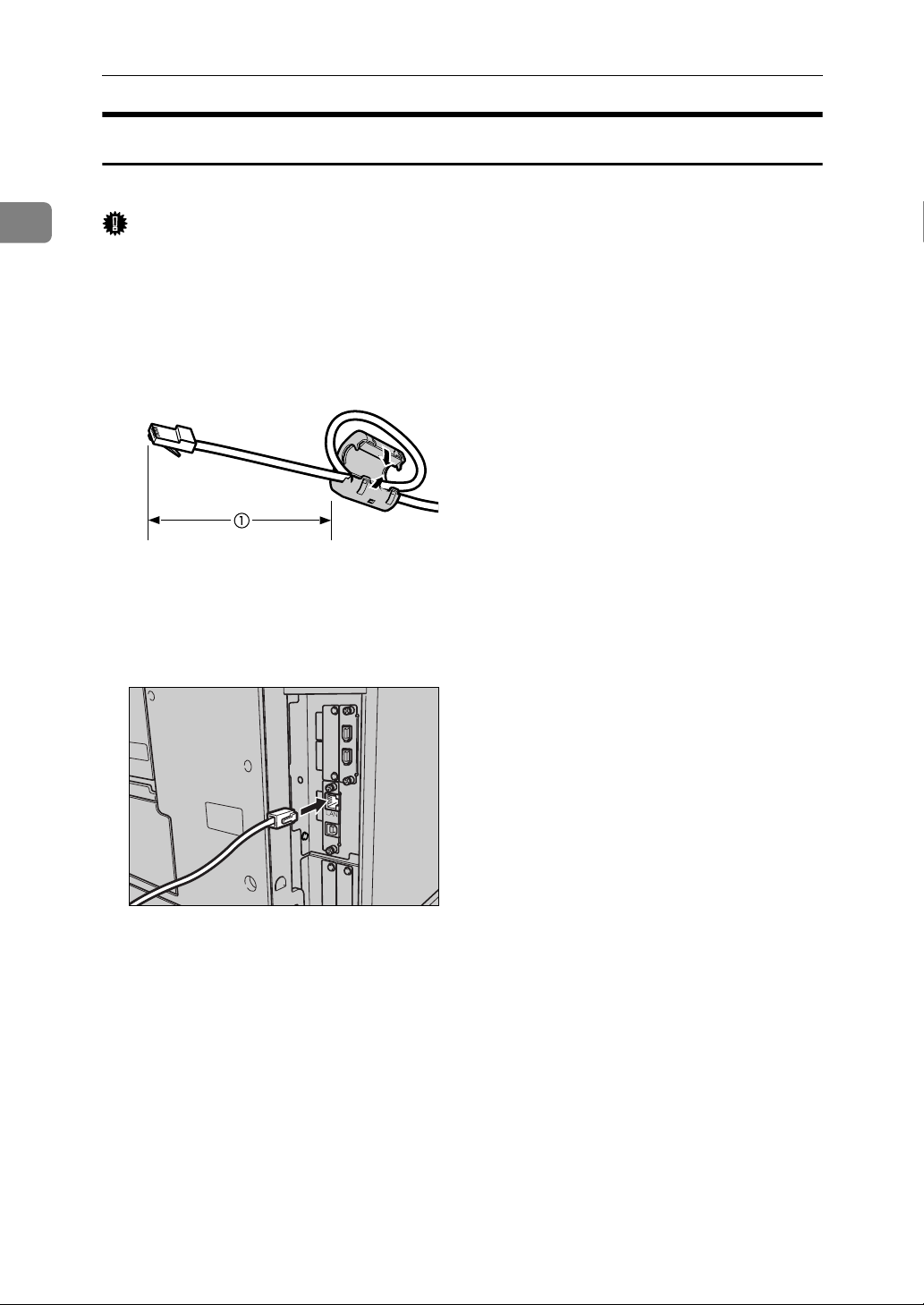
A A ferrite core for the Ethernet cable is supplied with this machine. The Eth-
ernet cable loop should be about 15 cm (5.9 inch) (1) from the machine end
of the cable.
AEV047S
B Make sure the main power switch on the machine is "Off".
C Connect the Ethernet interface cable to the 10BASE-T/100BASE-TX port.
AMM007S
D Connect the other end of the Ethernet cable to a network connection device
such as a hub.
6
Page 15
Connecting to the Interfaces
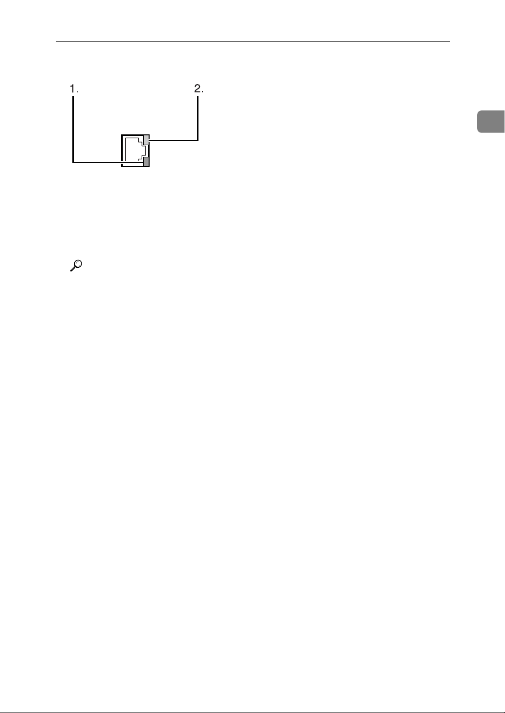
E Turn the main power switch of the machine on.
AMM008S
A Indicator (green)
Remains green when the machine is properly connected to the network.
B Indicator (yellow)
Turns yellow when 100 BASE-TX is operating. Turns off when 10 BASE-T
is operating.
Reference
"Turning On the Power" About This Machine
"Preparing the Machine" Printer Reference
1
7
Page 16
Connecting the Machine
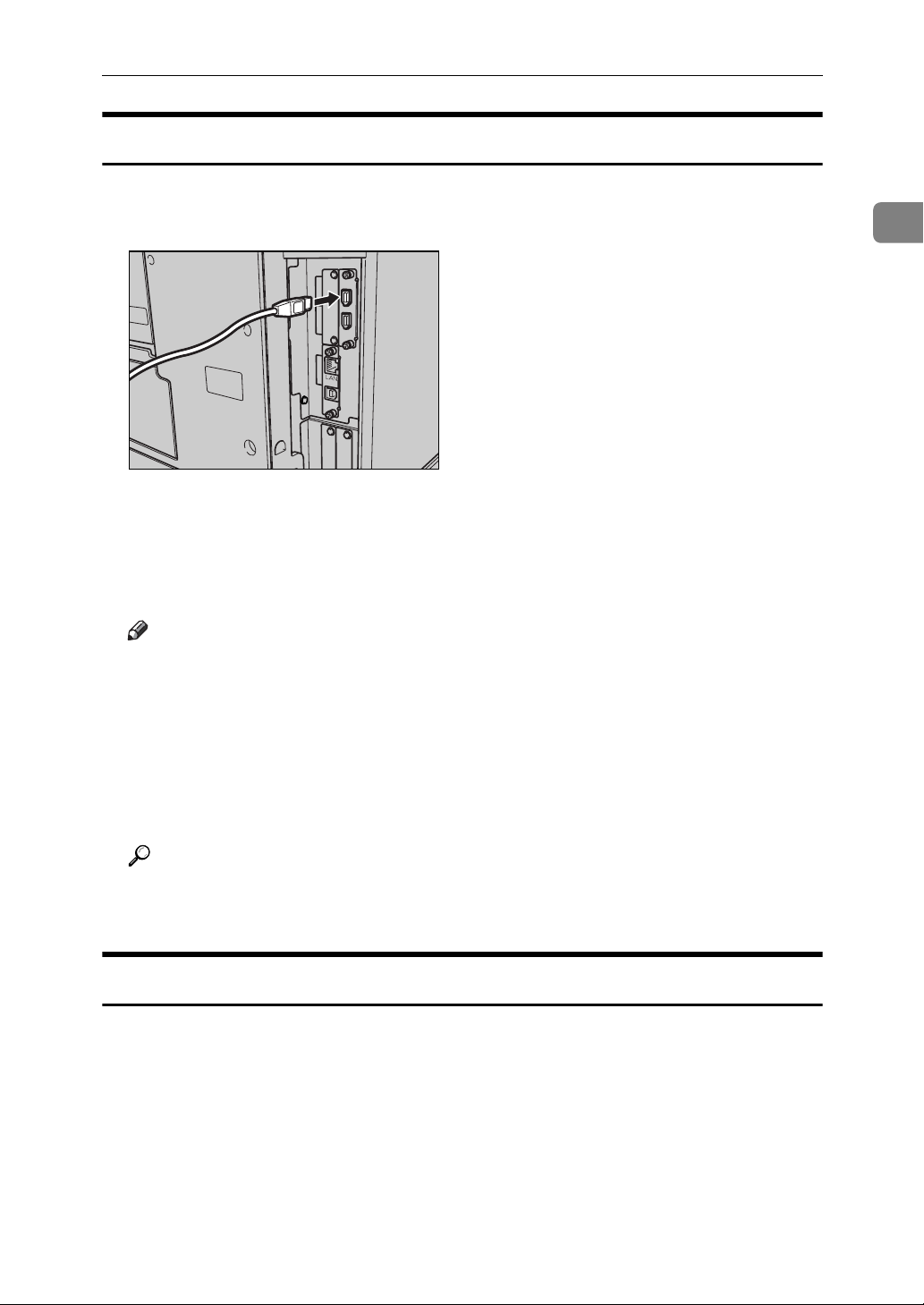
Connecting to the USB Interface
Connect the USB2.0 interface cable to the USB2.0 port.
1
A Connect the USB 2.0 interface cable to the USB2.0 port.
AMM009S
B Connect the other end to the USB port on the host computer.
Note
❒ Purchase a USB cable separately according to a personal computer in use.
❒ The USB 2.0 interface board is supported by Windows Me / 2000 / XP,
Windows Server 2003, Mac OS X v10.3.3 or higher.
• For Windows Me:
Make sure to install "USB Printing Support". If USB 2.0 is used with
Windows Me, only a speed equal to that of USB 1.1 is possible.
•For Mac OS:
To use Macintosh, the machine must be equipped with the optional
PostScript 3 unit. If USB 2.0 is used with Mac OS X v10.3.3 or higher, a
transfer speed of USB 2.0 is supported.
❒ For details about installing the printer driver, see "Preparing the Machine"
Printer Reference.
Reference
"Preparing the Machine" Printer Reference
8
Page 17
Connecting to the Interfaces
Connecting to the IEEE 1394 Interface
Connect the IEEE 1394 interface cable to the IEEE 1394 interface board.
A Connect the IEEE 1394 interface cable to the IEEE 1394 port.
AMM010S
B For IEEE 1394 (SCSI print) connection, plug the other end of the cable into
the interface connector on the host computer.
Make sure about the shape of the connector to the computer. Fasten the connector securely to the computer.
Note
❒ Use the interface cable supplied with the IEEE 1394 interface board (op-
tional).
❒ Make sure the interface cable is not looped.
❒ Two interface ports are available for connecting the IEEE 1394 interface ca-
ble. Either is suitable.
❒ For details about installing the printer driver, see "Preparing the Machine"
Printer Reference.
1
Reference
"Turning On the Power" About this machine
"Preparing the Machine" Printer Reference
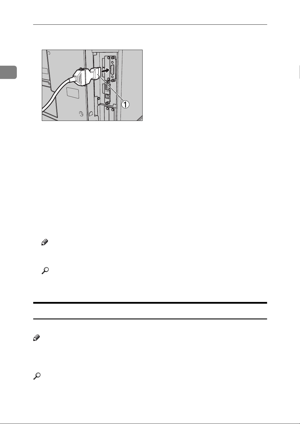
Connecting to the IEEE 1284 Interface
Connect the IEEE 1284 interface cable to the IEEE 1284 interface board.
A Make sure the main power switch on the machine is "Off".
If the main power switch is turned "On", turn it "Off".
B Turn off the main power switch of the host computer
9
Page 18
1
Connecting the Machine
C Connect the IEEE 1284 interface cable to the IEEE 1284 port.
AMB011S
To make the connection, use the conversion connector (1) supplied with the
IEEE 1284 interface board.
D Plug the other end of the cable into the interface connector on the host com-
puter.
Make sure about the shape of the connector to the computer. Fasten the connector securely to the computer.
E Turn the main power switch of the machine "On".
F Turn on the host computer.
When using Windows 95/98/Me/2000/XP and Windows Server 2003, a
printer driver installation screen might appear when the computer is turned
on. If this happens, click [Cancel] on the screen.
Note
❒ For details about installing the printer driver, see "Preparing the Machine"
Printer Reference
Reference
"Turning On the Power" About this machine
"Preparing the Machine" Printer Reference
Connecting to the IEEE 802.11b (Wireless LAN) Interface
Connecting to the IEEE 802.11b (wireless LAN) interface.
Note
❒ Check the setting of IPv4 address and subnet mask of this machine.
❒ For how to set IPv4 address and subnet mask from the control panel of the
machine, see "Interface Settings".
10
Reference
p.55 “Network”
Page 19
Connecting to the Interfaces
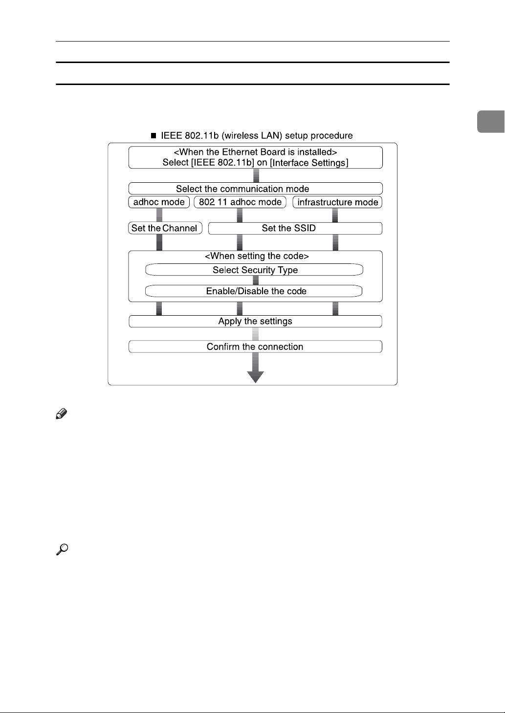
Setup Procedure
Setup IEEE 802.11b (wireless LAN) according to the following flow:
1
AME006S
Note
❒ Select [802.11 Ad-hoc Mode] when connecting Windows XP as a wireless LAN
client using Windows XP standard driver or utilities, or when not using the
infrastructure mode.
❒ For details about how to make settings of wireless LAN from the control panel
on the machine, see "IEEE 802.11b".
❒ For details about how to make settings of wireless LAN from other than the
control panel on the machine, see "Using Utilities to Make Settings".
❒ For details about the setting items, see "IEEE 802.11b".
Reference
p.62 “IEEE 802.11b”
p.33 “Using Utilities to Make Settings”
11
Page 20
1
Connecting the Machine
Checking the Connection
Check the wireless LAN connection.
Make sure the LED of the IEEE 802.11b interface unit is lit.
❖ When using in infrastructure mode
1
2
ZGDH600J
1. If [LAN Type] on the [Interface Settings] / [Network] screen is not set to [IEEE
802.11b], it does not light, even if the main power is on.
2. If it is connected properly to the network, the LED is green when in infra-
structure mode. If the LED is blinking, the machine is searching for devices.
❖ When using in adhoc mode / 802.11 adhoc mode
1
2
ZGDH600J
1. If the IEEE 802.11b interface unit is working, it is lit in orange.
2. If it is connected properly to the network, the LED is green when in adhoc
mode or 802.11 adhoc mode. If the LED is blinking, the machine is searching
for devices. The LED will light after a few seconds.
Print the configuration page to verify settings.
Note
❒ For more information about printing a configuration page, see "Print List".
Reference
p.138 “Printing the configuration page”
12
Page 21

Connecting to the Interfaces
Checking the Signal
When using in infrastructure mode, you can check the machine's radio wave status using the control panel.
A Press [System Settings].
B Press [Interface Settings].
C Press [IEEE 802.11b].
D Press [Wireless LAN Signal].
The machine's radio wave status appears.
E After checking radio wave status, press [Exit].
F Press the {User Tools/Counter} key to return to the User Tools / Counter / Inquiry
menu.
Note
❒ To check the radio wave status, press [IEEE 802.11b] under [LAN Type] on the
[Network] screen.
1
13
Page 22

1
Connecting the Machine
Network Settings
This section describes the network settings you can change with User Tools (System Settings). Make settings according to functions you want to use and the interface to be connected.
Important
❒ These settings should be made by the systems administrator, or after consult-
ing with the systems administrator.
Settings Required to Use the Printer
This section lists the settings required for using the printer function.
Ethernet
This section lists the settings required for using the printer function with an Ethernet connection.
For details about specifying the settings, see "Interface Settings".
Heading Setting Item Setting Requirements
Interface Settings/Network Machine IPv4 Address Mandatory
Interface Settings/Network IPv4 Gateway Address As required
Interface Settings/Network Machine IPv6 Address As required
Interface Settings/Network IPv6 Gateway Address As required
Interface Settings/Network IPv6 Stateless Address Autoconfigu-
ration
Interface Settings/Network DNS Configuration As required
Interface Settings/Network DDNS Configuration As required
Interface Settings/Network Domain Name As required
Interface Settings/Network WINS Configuration As required
Interface Settings/Network Effective Protocol Mandatory
Interface Settings/Network NCP Delivery Protocol As required
Interface Settings/Network NW Frame Type As required
Interface Settings/Network SMB Computer Name As required
Interface Settings/Network SMB Work Group As required
As required
14
Interface Settings/Network Ethernet Speed As required
Interface Settings/Network LAN Type Mandatory
Interface Settings/Network Permit SNMPv3 Communication As required
Interface Settings/Network Permit SSL/TLS Communication As required
Interface Settings/Network Host Name As required
Page 23

Network Settings
Heading Setting Item Setting Requirements
Interface Settings/Network Machine Name As required
Note
❒ IPv6 can be used only for the printer function.
❒ In [Effective Protocol], check that the protocol you want to use is set to [Active].
❒ [LAN Type] is displayed when optional wireless LAN board is installed. If Eth-
ernet and IEEE 802.11b (wireless LAN) are both connected, the selected interface has priority.
Reference
p.55 “Interface Settings”
p.65 “File Transfer”
IEEE 1394 (IPv4 over 1394)
This section describes necessary set items for using Printer with IEEE 1394 interface cable.
For details about specifying the settings, see "Interface Settings" and "File Transfer".
1
Heading Setting Item Setting Requirements
Interface Settings/IEEE 1394 IPv4 Address Mandatory
Interface Settings/IEEE 1394 DDNS Configuration As required
Interface Settings/IEEE 1394 Host Name As required
Interface Settings/IEEE 1394 Domain Name As required
Interface Settings/IEEE 1394 WINS Configuration As required
Interface Settings/IEEE 1394 IPv4 over 1394 Mandatory
Interface Settings/Network IPv4 Gateway Address As required
Interface Settings/Network DNS Configuration As required
Interface Settings/Network Effective Protocol Mandatory
Note
❒ [IEEE 1394]appears when optional IEEE 1394 interface board is installed.
❒ As to [Effective Protocol], check if the protocol to use is set as [Active].
Reference
p.55 “Interface Settings”
p.65 “File Transfer”
15
Page 24

1
Connecting the Machine
IEEE 802.11b (wireless LAN)
This section describes necessary set items for using Printer with IEEE 802.11b
(wireless LAN).
For details about specifying the settings, see "Interface Settings" and "File Transfer".
Heading Setting Item Setting Requirements
Interface Settings/Network Machine IPv4 Address Mandatory
Interface Settings/Network IPv4 Gateway Address As required
Interface Settings/Network Machine IPv6 Address As required
Interface Settings/Network IPv6 Gateway Address As required
Interface Settings/Network IPv6 Stateless Address Autoconfigu-
ration
Interface Settings/Network DNS Configuration As required
Interface Settings/Network DDNS Configuration As required
Interface Settings/Network Domain Name As required
Interface Settings/Network WINS Configuration As required
Interface Settings/Network Effective Protocol Mandatory
Interface Settings/Network NCP Delivery Protocol As required
Interface Settings/Network NW Frame Type As required
Interface Settings/Network SMB Computer Name As required
Interface Settings/Network SMB Work Group As required
Interface Settings/Network LAN Type Mandatory
Interface Settings/Network Permit SNMPv3 Communication As required
Interface Settings/Network Permit SSL/TLS Communication As required
Interface Settings/Network Host Name As required
Interface Settings/Network Machine Name As required
Interface Settings/
IEEE 802.11b
Communication Mode Mandatory
As required
16
Interface Settings/
IEEE 802.11b
Interface Settings/
IEEE 802.11b
Interface Settings/
IEEE 802.11b
Interface Settings/
IEEE 802.11b
SSID Setting As required
Channel As required
Security Method As required
Transmission Speed As required
Page 25
Network Settings
Note
❒ As to [Effective Protocol], check if the protocol to use is set as [Active].
❒ [IEEE 802.11b] and [LAN Type] are displayed when optional wireless LAN inter-
face board is installed. If both Ethernet and wireless LAN (IEEE 802.11b) are
connected, the selected interface takes precedence.
Reference
p.55 “Interface Settings”
p.65 “File Transfer”
Settings Required to Use E-mail Function
This section describes necessary set items for sending e-mail.
Ethernet
This section describes necessary set items for sending e-mail with Ethernet cable.
For details about specifying the settings, see "Interface Settings" and "File Transfer".
1
Heading Setting Item Setting Requirements
Interface Settings/Network Machine IPv4 Address Mandatory
Interface Settings/Network IPv4 Gateway Address Mandatory
Interface Settings/Network DNS Configuration As required
Interface Settings/Network DDNS Configuration As required
Interface Settings/Network Domain Name As required
Interface Settings/Network WINS Configuration As required
Interface Settings/Network Effective Protocol Mandatory
Interface Settings/Network Ethernet Speed As required
Interface Settings/Network LAN Type Mandatory
Interface Settings/Network Permit SNMPv3 Communication As required
Interface Settings/Network Permit SSL/TLS Communication As required
Interface Settings/Network Host Name As required
File Transfer SMTP Server Mandatory
File Transfer SMTP Authentication As required
File Transfer POP before SMTP As required
File Transfer Reception Protocol As required
File Transfer POP3/IMAP4 Settings As required
File Transfer Administrator's E-mail Address As required
File Transfer E-mail Communication Port As required
File Transfer Program / Change /
Delete E-mail Message
As required
17
Page 26

Connecting the Machine
Heading Setting Item Setting Requirements
File Transfer Scanner Resend Interval Time As required
File Transfer Number of Scanner Resends As required
1
Note
❒ As to [Effective Protocol], check if the protocol to use is set as [Active].
❒ [LAN Type] is displayed when optional wireless LAN interface board is in-
stalled. If both ethernet and wireless LAN (IEEE 802.11b) are connected, the
selected interface takes precedence.
❒ When setting [POP before SMTP] to [On], also make setting for[Reception Proto-
col] and [POP3 / IMAP4 Settings].
❒ When setting [POP before SMTP] to [On], check[POP3] port number in [E-mail
Communication Port].
Reference
p.55 “Interface Settings”
p.65 “File Transfer”
IEEE 1394 (IPv4 over 1394)
This section describes necessary set items for sending e-mail with IEEE 1394 interface cable.
For details about specifying the settings, see "Interface Settings" and "File Transfer".
Heading Setting Item Setting Requirements
18
Interface Settings/IEEE 1394 IPv4 Address Mandatory
Interface Settings/IEEE 1394 DDNS Configuration As required
Interface Settings/IEEE 1394 Host Name As required
Interface Settings/IEEE 1394 Domain Name As required
Interface Settings/IEEE 1394 WINS Configuration As required
Interface Settings/IEEE 1394 IPv4 over 1394 Mandatory
Interface Settings/Network IPv4 Gateway Address Mandatory
Interface Settings/Network DNS Configuration As required
Interface Settings/Network Effective Protocol Mandatory
File Transfer SMTP Server Mandatory
File Transfer SMTP Authentication As required
File Transfer POP before SMTP As required
File Transfer Reception Protocol As required
File Transfer POP3/IMAP4 Settings As required
File Transfer Administrator's E-mail Address As required
File Transfer E-mail Communication Port As required
Page 27

Network Settings
Heading Setting Item Setting Requirements
File Transfer Program / Change /
Delete E-mail Message
File Transfer Scanner Resend Interval Time As required
File Transfer Number of Scanner Resends As required
As required
Note
❒ [IEEE 1394] is displayed when optional IEEE 1394 interface board is installed.
❒ As to [Effective Protocol], check if the protocol to use is set as [Active].
❒ When setting [POP before SMTP] to [On], also make setting for[Reception Proto-
col] and [POP3 / IMAP4 Settings].
❒ When setting [POP before SMTP] to [On], check[POP3] port number in [E-mail
Communication Port].
Reference
p.55 “Interface Settings”
p.65 “File Transfer”
IEEE 802.11b (wireless LAN)
This section describes necessary set items for sending e-mail with IEEE 802.11b
(wireless LAN).
For details about specifying the settings, see "Interface Settings" and "File Transfer".
1
Heading Setting Item Setting Requirements
Interface Settings/Network Machine IPv4 Address Mandatory
Interface Settings/Network IPv4 Gateway Address Mandatory
Interface Settings/Network DNS Configuration As required
Interface Settings/Network DDNS Configuration As required
Interface Settings/Network Domain Name As required
Interface Settings/Network WINS Configuration As required
Interface Settings/Network Effective Protocol Mandatory
Interface Settings/Network LAN Type Mandatory
Interface Settings/Network Permit SNMPv3 Communication As required
Interface Settings/Network Permit SSL/TLS Communication As required
Interface Settings/Network Host Name As required
Interface Settings/
IEEE 802.11b
Interface Settings/
IEEE 802.11b
Interface Settings/
IEEE 802.11b
Communication Mode Mandatory
SSID Setting As required
Channel As required
19
Page 28
Connecting the Machine
Heading Setting Item Setting Requirements
1
Interface Settings/
IEEE 802.11b
Interface Settings/
IEEE 802.11b
File Transfer SMTP Server Mandatory
File Transfer SMTP Authentication As required
File Transfer POP before SMTP As required
File Transfer Reception Protocol As required
File Transfer POP3/IMAP4 Settings As required
File Transfer Administrator's E-mail Address As required
File Transfer E-mail Communication Port As required
File Transfer Program / Change /
File Transfer Scanner Resend Interval Time As required
File Transfer Number of Scanner Resends As required
Security Method As required
Transmission Speed As required
As required
Delete E-mail Message
Note
❒ As to [Effective Protocol], check if the protocol to use is set as [Active].
❒ [LAN Type] is displayed when optional wireless LAN interface board is in-
stalled. If both ethernet and wireless LAN (IEEE 802.11b) are connected, the
selected interface takes precedence.
❒ When setting [POP before SMTP] to [On], also make setting for[Reception Proto-
col] and [POP3 / IMAP4 Settings].
❒ When setting [POP before SMTP] to [On], check[POP3] port number in [E-mail
Communication Port].
20
Reference
p.55 “Interface Settings”
p.65 “File Transfer”
Page 29
Settings Required to Use Scan to Folder Function
This section describes necessary set items for sending file.
Network Settings
Ethernet
This section describes necessary set items for sending file with ethernet cable.
For details about specifying the settings, see "Interface Settings" and "File Transfer".
Heading Setting Item Setting Requirements
Interface Settings/Network Machine IPv4 Address Mandatory
Interface Settings/Network IPv4 Gateway Address Mandatory
Interface Settings/Network DNS Configuration As required
Interface Settings/Network DDNS Configuration As required
Interface Settings/Network Domain Name As required
Interface Settings/Network WINS Configuration As required
Interface Settings/Network Effective Protocol Mandatory
Interface Settings/Network Ethernet Speed As required
Interface Settings/Network LAN Type Mandatory
Interface Settings/Network Permit SNMPv3 Communication As required
Interface Settings/Network Permit SSL/TLS Communication As required
Interface Settings/Network Host Name As required
1
File Transfer Scanner Resend Interval Time As required
File Transfer Number of Scanner Resends As required
Note
❒ As to [Effective Protocol], check if the protocol to use is set as [Active].
❒ [LAN Type] is displayed when optional wireless LAN interface board is in-
stalled. If both ethernet and wireless LAN (IEEE 802.11b) are connected, the
selected interface takes precedence.
Reference
p.55 “Interface Settings”
p.65 “File Transfer”
21
Page 30
1
Connecting the Machine
IEEE 1394 (IPv4 over 1394)
This section describes necessary set items for sending file with IEEE 1394 interface cable.
For details about specifying the settings, see "Interface Settings" and "File Transfer".
Heading Setting Item Setting Requirements
Interface Settings/IEEE 1394 IPv4 Address Mandatory
Interface Settings/IEEE 1394 DDNS Configuration As required
Interface Settings/IEEE 1394 Host Name As required
Interface Settings/IEEE 1394 Domain Name As required
Interface Settings/IEEE 1394 WINS Configuration As required
Interface Settings/IEEE 1394 IPv4 over 1394 Mandatory
Interface Settings/Network IPv4 Gateway Address Mandatory
Interface Settings/Network DNS Configuration As required
Interface Settings/Network Effective Protocol Mandatory
File Transfer Scanner Resend Interval Time As required
File Transfer Number of Scanner Resends As required
Note
❒ [IEEE 1394] is displayed when optional IEEE 1394 interface board is installed.
❒ As to [Effective Protocol], check if the protocol to use is set as [Active].
Reference
p.55 “Interface Settings”
p.65 “File Transfer”
22
Page 31

Network Settings
IEEE 802.11b (wireless LAN)
This section describes necessary set items for sending file with IEEE 802.11b
(wireless LAN).
For details about specifying the settings, see "Interface Settings" and "File Transfer".
Heading Setting Item Setting Requirements
Interface Settings/Network Machine IPv4 Address Mandatory
Interface Settings/Network IPv4 Gateway Address Mandatory
Interface Settings/Network DNS Configuration As required
Interface Settings/Network DDNS Configuration As required
Interface Settings/Network Domain Name As required
Interface Settings/Network WINS Configuration As required
Interface Settings/Network Effective Protocol Mandatory
Interface Settings/Network LAN Type Mandatory
Interface Settings/Network Permit SNMPv3 Communication As required
Interface Settings/Network Permit SSL/TLS Communication As required
1
Interface Settings/Network Host Name As required
Interface Settings/
IEEE 802.11b
Interface Settings/
IEEE 802.11b
Interface Settings/
IEEE 802.11b
Interface Settings/
IEEE 802.11b
Interface Settings/
IEEE 802.11b
File Transfer Scanner Resend Interval Time As required
File Transfer Number of Scanner Resends As required
Communication Mode Mandatory
SSID Setting As required
Channel As required
Security Method As required
Transmission Speed As required
Note
❒ As to [Effective Protocol], check if the protocol to use is set as [Active].
❒ [IEEE 802.11b] and [LAN Type] are displayed when optional wireless LAN inter-
face board is installed. If both ethernet and wireless LAN (IEEE 802.11b) are
connected, the selected interface takes precedence.
Reference
p.55 “Interface Settings”
p.65 “File Transfer”
23
Page 32

Connecting the Machine
Settings Required to Use the Network Delivery Scanner
This section describes necessary set items for delivering data to network.
1
Ethernet
This section describes necessary set items for delivering data to network with
ethernet cable.
For details about specifying the settings, see "Interface Settings" and "File Transfer".
Heading Setting Item Setting Requirements
Interface Settings/Network Machine IPv4 Address Mandatory
Interface Settings/Network IPv4 Gateway Address As required
Interface Settings/Network DNS Configuration As required
Interface Settings/Network DDNS Configuration As required
Interface Settings/Network Domain Name As required
Interface Settings/Network WINS Configuration As required
Interface Settings/Network Effective Protocol Mandatory
Interface Settings/Network Ethernet Speed As required
Interface Settings/Network LAN Type Mandatory
Interface Settings/Network Permit SNMPv3 Communication As required
Interface Settings/Network Permit SSL/TLS Communication As required
Interface Settings/Network Host Name As required
File Transfer Delivery Option As required
File Transfer Scanner Resend Interval Time As required
File Transfer Number of Scanner Resends As required
Note
❒ As to [Effective Protocol], check if the protocol to use is set as [Active].
❒ [LAN Type] is displayed when optional wireless LAN interface board is in-
stalled. When both ethernet and wireless LAN (IEEE 802.11b) are connected,
the selected interface takes precedence.
❒ If [Delivery Option] is set to [On], check that IPv4 Address is set.
Reference
p.55 “Interface Settings”
p.65 “File Transfer”
24
Page 33

Network Settings
IEEE 1394 (IPv4 over 1394)
This section describes necessary set items for delivering data to network with
IEEE 1394 interface cable.
For details about specifying the settings, see "Interface Settings" and "File Transfer".
Heading Setting Item Setting Requirements
Interface Settings/IEEE 1394 IPv4 Address Mandatory
Interface Settings/IEEE 1394 DDNS Configuration As required
Interface Settings/IEEE 1394 Host Name As required
Interface Settings/IEEE 1394 Domain Name As required
Interface Settings/IEEE 1394 WINS Configuration As required
Interface Settings/IEEE 1394 IPv4 over 1394 Mandatory
Interface Settings/Network IPv4 Gateway Address As required
Interface Settings/Network DNS Configuration As required
Interface Settings/Network Effective Protocol Mandatory
File Transfer Delivery Option As required
1
File Transfer Scanner Resend Interval Time As required
File Transfer Number of Scanner Resends As required
Note
❒ [IEEE 1394] is displayed when optional IEEE 1394 interface board is installed.
❒ As to [Effective Protocol], check if the protocol to use is set as [Active].
❒ If [Delivery Option] is set to [On], check that IPv4 Address is set.
Reference
p.55 “Interface Settings”
p.65 “File Transfer”
25
Page 34

1
Connecting the Machine
IEEE 802.11b (wireless LAN)
This section describes necessary set items for delivering data to network with
IEEE 802.11b (wireless LAN).
For details about specifying the settings, see "Interface Settings" and "File Transfer".
Heading Setting Item Setting Requirements
Interface Settings/Network Machine IPv4 Address Mandatory
Interface Settings/Network IPv4 Gateway Address As required
Interface Settings/Network DNS Configuration As required
Interface Settings/Network DDNS Configuration As required
Interface Settings/Network Domain Name As required
Interface Settings/Network WINS Configuration As required
Interface Settings/Network Effective Protocol Mandatory
Interface Settings/Network LAN Type Mandatory
Interface Settings/Network Permit SNMPv3 Communication As required
Interface Settings/Network Permit SSL/TLS Communication As required
Interface Settings/Network Host Name As required
Interface Settings/
IEEE 802.11b
Interface Settings/
IEEE 802.11b
Interface Settings/
IEEE 802.11b
Interface Settings/
IEEE 802.11b
Interface Settings/
IEEE 802.11b
File Transfer Delivery Option As required
File Transfer Scanner Resend Interval Time As required
File Transfer Number of Scanner Resends As required
Communication Mode Mandatory
SSID Setting As required
Channel As required
Security Method As required
Transmission Speed As required
Note
❒ As to [Effective Protocol], check if the protocol to use is set as [Active].
❒ [IEEE 802.11b] and [LAN Type] are displayed when optional wireless LAN inter-
face board is installed. When both Ethernet and wireless LAN (IEEE 802.11b)
are connected, the selected interface takes precedence.
❒ If [Delivery Option] is set to [On], check that IPv4 Address is set.
Reference
p.55 “Interface Settings”
p.65 “File Transfer”
26
Page 35

Network Settings
Settings Required to Use Network TWAIN Scanner
This section describes necessary set items for using TWAIN Scanner under the
network environment.
Ethernet
This section describes necessary set items for using network TWAIN Scanner
with Ethernet cable.
For details about specifying the settings, see "Interface Settings" and "File Transfer".
Heading Setting Item Setting Requirements
Interface Settings/Network Machine IPv4 Address Mandatory
Interface Settings/Network IPv4 Gateway Address As required
Interface Settings/Network DNS Configuration As required
Interface Settings/Network DDNS Configuration As required
Interface Settings/Network Domain Name As required
1
Interface Settings/Network WINS Configuration As required
Interface Settings/Network Effective Protocol Mandatory
Interface Settings/Network LAN Type Mandatory
Interface Settings/Network Ethernet Speed As required
Interface Settings/Network Permit SNMPv3 Communication As required
Interface Settings/Network Permit SSL/TLS Communication As required
Interface Settings/Network Host Name As required
Note
❒ As to [Effective Protocol], check if the protocol to use is set as [Active].
❒ [LAN Type] is displayed when optional wireless LAN interface board is in-
stalled. When both Ethernet and wireless LAN (IEEE 802.11b) are connected,
the selected interface takes precedence.
Reference
p.55 “Interface Settings”
p.65 “File Transfer”
27
Page 36

1
Connecting the Machine
IEEE 1394 (IPv4 over 1394)
This section describes necessary set items for using network TWAIN Scanner
with IEEE 1394 interface cable.
For details about specifying the settings, see "Interface Settings" and "File Transfer".
Heading Setting Item Setting Requirements
Interface Settings/IEEE 1394 IPv4 Address Mandatory
Interface Settings/IEEE 1394 DDNS Configuration As required
Interface Settings/IEEE 1394 Host Name As required
Interface Settings/IEEE 1394 Domain Name As required
Interface Settings/IEEE 1394 WINS Configuration As required
Interface Settings/IEEE 1394 IPv4 over 1394 Mandatory
Interface Settings/Network IPv4 Gateway Address As required
Interface Settings/Network DNS Configuration As required
Interface Settings/Network Effective Protocol Mandatory
Note
❒ [IEEE 1394] is displayed when optional IEEE 1394 interface board is installed.
❒ As to [Effective Protocol], check if the protocol to use is set as [Active].
Reference
p.55 “Interface Settings”
p.65 “File Transfer”
28
Page 37

Network Settings
IEEE 802.11b (wireless LAN)
This section describes necessary set items for using network TWAIN Scanner
with IEEE 802.11b (wireless LAN).
For details about specifying the settings, see "Interface Settings" and "File Transfer".
Heading Setting Item Setting Requirements
Interface Settings/Network Machine IPv4 Address Mandatory
Interface Settings/Network IPv4 Gateway Address As required
Interface Settings/Network DNS Configuration As required
Interface Settings/Network DDNS Configuration As required
Interface Settings/Network Domain Name As required
Interface Settings/Network WINS Configuration As required
Interface Settings/Network Effective Protocol Mandatory
Interface Settings/Network LAN Type Mandatory
Interface Settings/Network Permit SNMPv3 Communication As required
Interface Settings/Network Permit SSL/TLS Communication As required
1
Interface Settings/Network Host Name As required
Interface Settings/
IEEE 802.11b
Interface Settings/
IEEE 802.11b
Interface Settings/
IEEE 802.11b
Interface Settings/
IEEE 802.11b
Interface Settings/
IEEE 802.11b
Communication Mode Mandatory
SSID Setting As required
Channel As required
Security Method As required
Transmission Speed As required
Note
❒ As to [Effective Protocol], check if the protocol to use is set as [Active].
❒ [IEEE 802.11b] and [LAN Type] are displayed when optional wireless LAN inter-
face board is installed. When both Ethernet and wireless LAN (IEEE 802.11b)
are connected, the selected interface takes precedence.
Reference
p.55 “Interface Settings”
p.65 “File Transfer”
29
Page 38

1
Connecting the Machine
Settings Required to Use Document Server
This section describes necessary set items for using Document Server function
under the network environment.
Ethernet
This section describes necessary set items for using Document Server function
with Ethernet cable.
For details about specifying the settings, see "Interface Settings" and "File Transfer".
Heading Setting Item Setting Requirements
Interface Settings/Network Machine IPv4 Address Mandatory
Interface Settings/Network IPv4 Gateway Address As required
Interface Settings/Network DNS Configuration As required
Interface Settings/Network DDNS Configuration As required
Interface Settings/Network Domain Name As required
Interface Settings/Network WINS Configuration As required
Interface Settings/Network Effective Protocol Mandatory
Interface Settings/Network Ethernet Speed As required
Interface Settings/Network LAN Type Mandatory
Interface Settings/Network Permit SNMPv3 Communication As required
Interface Settings/Network Permit SSL/TLS Communication As required
Interface Settings/Network Host Name As required
Note
❒ As to [Effective Protocol], check if the protocol to use is set as [Active].
❒ [LAN Type] is displayed when optional wireless LAN interface board is in-
stalled. When both Ethernet and wireless LAN (IEEE 802.11b) are connected,
the selected interface takes precedence.
Reference
p.55 “Interface Settings”
p.65 “File Transfer”
30
Page 39

Network Settings
IEEE 1394 (IPv4 over 1394)
This section describes necessary set items for using Document Server function
with IEEE 1394 interface cable.
For details about specifying the settings, see "Interface Settings" and "File Transfer".
Heading Setting Item Setting Requirements
Interface Settings/IEEE 1394 IPv4 Address Mandatory
Interface Settings/IEEE 1394 DDNS Configuration As required
Interface Settings/IEEE 1394 Host Name As required
Interface Settings/IEEE 1394 Domain Name As required
Interface Settings/IEEE 1394 WINS Configuration As required
Interface Settings/IEEE 1394 IPv4 over 1394 Mandatory
Interface Settings/Network IPv4 Gateway Address As required
Interface Settings/Network DNS Configuration As required
Interface Settings/Network Effective Protocol Mandatory
1
Note
❒ [IEEE 1394] is displayed when optional IEEE 1394 interface board is installed.
❒ As to [Effective Protocol], check if the protocol to use is set as [Active].
Reference
p.55 “Interface Settings”
p.65 “File Transfer”
31
Page 40

1
Connecting the Machine
IEEE 802.11b (wireless LAN)
This section describes necessary set items for using Document Server function
with IEEE 802.11b (wireless LAN).
For details about specifying the settings, see "Interface Settings" and "File Transfer".
Heading Setting Item Setting Requirements
Interface Settings/Network Machine IPv4 Address Mandatory
Interface Settings/Network IPv4 Gateway Address As required
Interface Settings/Network DNS Configuration As required
Interface Settings/Network DDNS Configuration As required
Interface Settings/Network Domain Name As required
Interface Settings/Network WINS Configuration As required
Interface Settings/Network Effective Protocol Mandatory
Interface Settings/Network LAN Type As required/Mandatory
Interface Settings/Network Permit SNMPv3 Communication As required
Interface Settings/Network Permit SSL/TLS Communication As required
Interface Settings/Network Host Name As required
Interface Settings/
IEEE 802.11b
Interface Settings/
IEEE 802.11b
Interface Settings/
IEEE 802.11b
Interface Settings/
IEEE 802.11b
Interface Settings/
IEEE 802.11b
Communication Mode Mandatory
SSID Setting As required
Channel As required
Security Method As required
Transmission Speed As required
Note
❒ As to [Effective Protocol], check if the protocol to use is set as [Active].
❒ [IEEE 802.11b] and [LAN Type] are displayed when optional wireless LAN inter-
face board is installed. When both Ethernet and wireless LAN (IEEE 802.11b)
are connected, the selected interface takes precedence.
Reference
p.55 “Interface Settings”
p.65 “File Transfer”
32
Page 41

Network Settings
Using Utilities to Make Settings
The network settings can be specified not only on the machine’s control panel
but also using utilities such as Web Image Monitor, SmartDeviceMonitor for Admin, and telnet.
Note
❒ For details about using Web Image Monitor, see "Using Web Image Monitor",
Network Guide.
❒ For details about using SmartDeviceMonitor for Admin, see "Using SmartDe-
viceMonitor for Admin", Network Guide.
❒ For Details about using telnet, see "Remote Maintenance", Network Guide.
Reference
"Using Web Image Monitor" Network Guide
"Using SmartDeviceMonitor for Admin" Network Guide
"Remote Maintenance by telnet" Network Guide
1
Interface Settings
Change set values of [Interface Settings] in [System Settings] of this machine by using Web Image Monitor, SmartDeviceMonitor for Admin, and telnet.
❖ [Network] → [Machine IPv4 Address] → [Auto-Obtain (DHCP)]
• Web Image Monitor:Can be used for specifying the setting.
• SmartDeviceMonitor for Admin:Can be used for specifying the setting.
• telnet:Can be used for specifying the setting.
❖ [Network] → [Machine IPv4 Address] → [Specify] → [IPv4 Address]
• Web Image Monitor:Can be used for specifying the setting.
• SmartDeviceMonitor for Admin:Can be used for specifying the setting.
• telnet:Can be used for specifying the setting.
❖ [Network] → [Machine IPv4 Address] → [Specify] → [Sub-net Mask]
• Web Image Monitor:Can be used for specifying the setting.
• SmartDeviceMonitor for Admin:Can be used for specifying the setting.
• telnet:Can be used for specifying the setting.
❖ [Network] → [IPv4 Gateway Address]
• Web Image Monitor:Can be used for specifying the setting.
• SmartDeviceMonitor for Admin:Can be used for specifying the setting.
• telnet:Can be used for specifying the setting.
33
Page 42

1
Connecting the Machine
❖ [Network] → [Machine IPv6 Address] → [Manual Configuration Address]
• Web Image Monitor:Can be used for specifying the setting.
• SmartDeviceMonitor for Admin:Cannot be used for specifying the setting.
• telnet:Can be used for specifying the setting.
❖ [Network] → [IPv6 Stateless Address Autoconfiguration]
• Web Image Monitor:Can be used for specifying the setting.
• SmartDeviceMonitor for Admin:Cannot be used for specifying the setting.
• telnet:Can be used for specifying the setting.
❖ [Network] → [DNS Configuration] → [Auto-Obtain (DHCP)]
• Web Image Monitor:Can be used for specifying the setting.
• SmartDeviceMonitor for Admin:Cannot be used for specifying the setting.
• telnet:Can be used for specifying the setting.
❖ [Network] → [DNS Configuration] → [Specify] → [DNS Server 1] - [DNS Server 3]
• Web Image Monitor:Can be used for specifying the setting.
• SmartDeviceMonitor for Admin:Cannot be used for specifying the setting.
• telnet:Can be used for specifying the setting.
❖ [Network] → [DDNS Configuration]
• Web Image Monitor:Can be used for specifying the setting.
• SmartDeviceMonitor for Admin:Cannot be used for specifying the setting.
• telnet:Can be used for specifying the setting.
❖ [Network] → [Domain Name] → [Auto-Obtain (DHCP)]
• Web Image Monitor:Can be used for specifying the setting.
• SmartDeviceMonitor for Admin:Cannot be used for specifying the setting.
• telnet:Can be used for specifying the setting.
❖ [Network] → [Domain Name] → [Specify] → [Domain Name]
• Web Image Monitor:Can be used for specifying the setting.
• SmartDeviceMonitor for Admin:Cannot be used for specifying the setting.
• telnet:Can be used for specifying the setting.
❖ [Network] → [WINS Configuration] → [Primary WINS Server] / [Secondary WINS
Server]
• Web Image Monitor:Can be used for specifying the setting.
• SmartDeviceMonitor for Admin:Cannot be used for specifying the setting.
• telnet:Can be used for specifying the setting.
34
Page 43

Network Settings
❖ [Network] → [WINS Configuration] → [Scope ID]
• Web Image Monitor:Can be used for specifying the setting.
• SmartDeviceMonitor for Admin:Cannot be used for specifying the setting.
• telnet:Can be used for specifying the setting.
❖ [Network] → [Effective Protocol] → [IPv4]
• Web Image Monitor:Can be used for specifying the setting.
• SmartDeviceMonitor for Admin:You can make the TCP/IP settings if
SmartDeviceMonitor for Admin is communicating with the machine using
IPX/SPX.
• telnet:Can be used for specifying the setting.
❖ [Network] → [Effective Protocol] → [IPv6]
• Web Image Monitor:Can be used for specifying the setting.
• SmartDeviceMonitor for Admin:Can be used for specifying the setting.
• telnet:Can be used for specifying the setting.
❖ [Network] → [Effective Protocol] → [NetWare]
1
• Web Image Monitor:Can be used for specifying the setting.
• SmartDeviceMonitor for Admin:You can make the IPX/SPX settings if
SmartDeviceMonitor for Admin is communicating with the machine using
TCP/IP.
• telnet:Can be used for specifying the setting.
❖ [Network] → [Effective Protocol] → [SMB]
• Web Image Monitor:Can be used for specifying the setting.
• SmartDeviceMonitor for Admin:Can be used for specifying the setting.
• telnet:Can be used for specifying the setting.
❖ [Network] → [Effective Protocol] → [AppleTalk]
• Web Image Monitor:Can be used for specifying the setting.
• SmartDeviceMonitor for Admin:Can be used for specifying the setting.
• telnet:Can be used for specifying the setting.
❖ [Network] → [NCP Delivery Protocol]
• Web Image Monitor:Can be used for specifying the setting.
• SmartDeviceMonitor for Admin:Can be used for specifying the setting.
• telnet:Cannot be used for specifying the setting.
❖ [Network] → [NW Frame Type] → [Auto Select]
• Web Image Monitor:Can be used for specifying the setting.
• SmartDeviceMonitor for Admin:Cannot be used for specifying the setting.
• telnet:Can be used for specifying the setting.
35
Page 44

1
Connecting the Machine
❖ [Network] → [NW Frame Type] → [Ethernet II]
• Web Image Monitor:Can be used for specifying the setting.
• SmartDeviceMonitor for Admin:Cannot be used for specifying the setting.
• telnet:Can be used for specifying the setting.
❖ [Network] → [NW Frame Type] → [Ethernet 802.2]
• Web Image Monitor:Can be used for specifying the setting.
• SmartDeviceMonitor for Admin:Cannot be used for specifying the setting.
• telnet:Can be used for specifying the setting.
❖ [Network] → [NW Frame Type] → [Ethernet 802.3]
• Web Image Monitor:Can be used for specifying the setting.
• SmartDeviceMonitor for Admin:Cannot be used for specifying the setting.
• telnet:Can be used for specifying the setting.
❖ [Network] → [NW Frame Type] → [Ethernet SNAP]
• Web Image Monitor:Can be used for specifying the setting.
• SmartDeviceMonitor for Admin:Cannot be used for specifying the setting.
• telnet:Can be used for specifying the setting.
❖ [Network] → [SMB Computer Name]
• Web Image Monitor:Can be used for specifying the setting.
• SmartDeviceMonitor for Admin:Cannot be used for specifying the setting.
• telnet:Can be used for specifying the setting.
❖ [Network] → [SMB Work Group]
• Web Image Monitor:Can be used for specifying the setting.
• SmartDeviceMonitor for Admin:Cannot be used for specifying the setting.
• telnet:Can be used for specifying the setting.
❖ [Network] → [Ethernet Speed]
• Web Image Monitor:Cannot be used for specifying the setting.
• SmartDeviceMonitor for Admin:Cannot be used for specifying the setting.
• telnet:Cannot be used for specifying the setting.
❖ [Network] → [LAN Type] → [Ethernet]
• Web Image Monitor:Can be used for specifying the setting.
• SmartDeviceMonitor for Admin:Cannot be used for specifying the setting.
• telnet:Can be used for specifying the setting.
36
Page 45

Network Settings
❖ [Network] → [LAN Type] → [IEEE 802.11b]
• Web Image Monitor:Can be used for specifying the setting.
• SmartDeviceMonitor for Admin:Cannot be used for specifying the setting.
• telnet:Can be used for specifying the setting.
❖ [Network] → [Host Name]
• Web Image Monitor:Can be used for specifying the setting.
• SmartDeviceMonitor for Admin:Can be used for specifying the setting.
• telnet:Can be used for specifying the setting.
❖ [Network] → [Machine Name]
• Web Image Monitor:Can be used for specifying the setting.
• SmartDeviceMonitor for Admin:Cannot be used for specifying the setting.
• telnet:Can be used for specifying the setting.
❖ [IEEE 1394] → [IPv4 Address] → [Auto-Obtain (DHCP)]
• Web Image Monitor:Can be used for specifying the setting.
• SmartDeviceMonitor for Admin:Cannot be used for specifying the setting.
• telnet:Can be used for specifying the setting.
1
❖ [IEEE 1394] → [IPv4 Address] → [Specify] → [Machine IPv4 Address]
• Web Image Monitor:Can be used for specifying the setting.
• SmartDeviceMonitor for Admin:Cannot be used for specifying the setting.
• telnet:Can be used for specifying the setting.
❖ [IEEE 1394] → [IPv4 Address] → [Specify] → [Sub-net Mask]
• Web Image Monitor:Can be used for specifying the setting.
• SmartDeviceMonitor for Admin:Cannot be used for specifying the setting.
• telnet:Can be used for specifying the setting.
❖ [IEEE 1394] → [DDNS Configuration]
• Web Image Monitor:Can be used for specifying the setting.
• SmartDeviceMonitor for Admin:Cannot be used for specifying the setting.
• telnet:Can be used for specifying the setting.
❖ [IEEE 1394] → [IPv4 over 1394]
• Web Image Monitor:Can be used for specifying the setting.
• SmartDeviceMonitor for Admin:Cannot be used for specifying the setting.
• telnet:Can be used for specifying the setting.
37
Page 46

1
Connecting the Machine
❖ [IEEE 1394] → [WINS Configuration] → [Primary WINS Server] / [Secondary WINS
Server]
• Web Image Monitor:Can be used for specifying the setting.
• SmartDeviceMonitor for Admin:Cannot be used for specifying the setting.
• telnet:Can be used for specifying the setting.
❖ [IEEE 1394] → [WINS Configuration] → [Scope ID]
• Web Image Monitor:Can be used for specifying the setting.
• SmartDeviceMonitor for Admin:Cannot be used for specifying the setting.
• telnet:Can be used for specifying the setting.
❖ [IEEE 1394] → [Host Name]
• Web Image Monitor:Can be used for specifying the setting.
• SmartDeviceMonitor for Admin:Cannot be used for specifying the setting.
• telnet:Can be used for specifying the setting.
❖ [IEEE 1394] → [Domain Name]
• Web Image Monitor:Can be used for specifying the setting.
• SmartDeviceMonitor for Admin:Cannot be used for specifying the setting.
• telnet:Can be used for specifying the setting.
❖ [IEEE 802.11b] → [Communication Mode]
• Web Image Monitor:Can be used for specifying the setting.
• SmartDeviceMonitor for Admin:Cannot be used for specifying the setting.
• telnet:Can be used for specifying the setting.
❖ [IEEE 802.11b] → [SSID Setting]
• Web Image Monitor:Can be used for specifying the setting.
• SmartDeviceMonitor for Admin:Cannot be used for specifying the setting.
• telnet:Can be used for specifying the setting.
❖ [IEEE 802.11b] → [Channel]
• Web Image Monitor:Can be used for specifying the setting.
• SmartDeviceMonitor for Admin:Cannot be used for specifying the setting.
• telnet:Can be used for specifying the setting.
❖ [IEEE 802.11b] → [Security Method]
• Web Image Monitor:Can be used for specifying the setting.
• SmartDeviceMonitor for Admin:Cannot be used for specifying the setting.
• telnet:Can be used for specifying the setting.
38
Page 47

Network Settings
❖ [IEEE 802.11b] → [Transmission Speed]
• Web Image Monitor:Cannot be used for specifying the setting.
• SmartDeviceMonitor for Admin:Cannot be used for specifying the setting.
• telnet:Can be used for specifying the setting.
❖ [File Transfer] → [SMTP Server]
• Web Image Monitor:Can be used for specifying the setting.
• SmartDeviceMonitor for Admin:Cannot be used for specifying the setting.
• telnet:Cannot be used for specifying the setting.
❖ [File Transfer] → [SMTP Authentication]
• Web Image Monitor:Can be used for specifying the setting.
• SmartDeviceMonitor for Admin:Cannot be used for specifying the setting.
• telnet:Cannot be used for specifying the setting.
❖ [File Transfer] → [POP before SMTP]
• Web Image Monitor:Can be used for specifying the setting.
• SmartDeviceMonitor for Admin:Cannot be used for specifying the setting.
• telnet:Cannot be used for specifying the setting.
1
❖ [File Transfer] → [Reception Protocol]
• Web Image Monitor:Can be used for specifying the setting.
• SmartDeviceMonitor for Admin:Cannot be used for specifying the setting.
• telnet:Cannot be used for specifying the setting.
❖ [File Transfer] → [POP3 / IMAP4 Settings]
• Web Image Monitor:Can be used for specifying the setting.
• SmartDeviceMonitor for Admin:Cannot be used for specifying the setting.
• telnet:Cannot be used for specifying the setting.
❖ [File Transfer] → [Administrator's E-mail Address]
• Web Image Monitor:Can be used for specifying the setting.
• SmartDeviceMonitor for Admin:Cannot be used for specifying the setting.
• telnet:Cannot be used for specifying the setting.
❖ [File Transfer] → [E-mail Communication Port]
• Web Image Monitor:Can be used for specifying the setting.
• SmartDeviceMonitor for Admin:Cannot be used for specifying the setting.
• telnet:Cannot be used for specifying the setting.
39
Page 48

1
Connecting the Machine
❖ [File Transfer] → [E-mail Reception Interval]
• Web Image Monitor:Can be used for specifying the setting.
• SmartDeviceMonitor for Admin:Cannot be used for specifying the setting.
• telnet:Cannot be used for specifying the setting.
❖ [File Transfer] → [Max. Reception E-mail Size]
• Web Image Monitor:Can be used for specifying the setting.
• SmartDeviceMonitor for Admin:Cannot be used for specifying the setting.
• telnet:Cannot be used for specifying the setting.
❖ [File Transfer] → [E-mail Storage in Server]
• Web Image Monitor:Can be used for specifying the setting.
• SmartDeviceMonitor for Admin:Cannot be used for specifying the setting.
• telnet:Cannot be used for specifying the setting.
❖ [File Transfer] → [Default User Name / Password (Send)]
• Web Image Monitor:Can be used for specifying the setting.
• SmartDeviceMonitor for Admin:Cannot be used for specifying the setting.
• telnet:Cannot be used for specifying the setting.
❖ [File Transfer] → [Scanner Resend Interval Time]
• Web Image Monitor:Cannot be used for specifying the setting.
• SmartDeviceMonitor for Admin:Cannot be used for specifying the setting.
• telnet:Cannot be used for specifying the setting.
❖ [File Transfer] → [Number of Scanner Resends]
• Web Image Monitor:Cannot be used for specifying the setting.
• SmartDeviceMonitor for Admin:Cannot be used for specifying the setting.
• telnet:Cannot be used for specifying the setting.
40
Page 49

2. System Settings
This chapter describes various items of [System Settings] available in this machine.
General Features
This section describes various items of [General Features] under [System Settings].
Default settings are shown in bold type.
❖ Program / Change / Delete User Text
You can register character strings you use frequently when specifying settings, such as “.com" and “Regards".
You can register up to 40 items.
• Program / Change
A Press [System Settings].
B Check that [General Features] is selected.
C Press [Program / Change / Delete User Text].
D Press [Program / Change]
E Select the user text you want to change.
To program new user text, press [Not Programmed].
F Press [OK].
G Press [Exit].
• Delete
A Press [System Settings].
B Check that [General Features] is selected.
C Press [Program / Change / Delete User Text].
D Press [Delete].
E Select the user text you want to delete.
F Press [Yes].
G Press [Exit].
❖ Panel Key Sound
The beeper (key tone) sounds when a key is pressed.
• On
•Off
41
Page 50

2
System Settings
❖ Warm-up Beeper (copier/Document Server)
You can have the beeper sound when the machine becomes ready to copy after leaving Energy Saver mode, or when the power is turned on.
• On
•Off
❖ Copy Count Display (copier/Document Server)
The copy counter can be set to show the number of copies made (count up) or
the number of copies yet to be made (count down).
• Up
• Down
❖ Function Priority
You can specify the mode to be displayed immediately after the operation
switch is turned on, or when System Reset mode is turned on.
• Copier
•Document Server
•Printer
•Scanner
❖ Print Priority
Print Priority is given to the mode selected.
• Display Mode
• Copier/Document Server
•Printer
•Interleave
•Job Order
When [Interleave] is selected, the current print job will be interrupted after a
maximum of five sheets.
❖ Function Reset Timer
You can set the length of time the machine waits before changing modes
when using the multi-access function.
This is useful if you are making many copies and have to change settings for
each copy. If you set a longer reset period, you can prevent interruption from
other functions.
The default time is "3 second(s)".
• Set Time
• Immediate
When you select [Set Time], enter the time (3–30 seconds, in 1 second increments) using the number keys.
❖ Interleave Print
Set the number of sheets to be output at the time of operation by interruption.
The machine is shipped from the factory with this value set to "10 sheets".
42
Page 51

❖ Output: Copier (copier)
You can specify a tray to which documents are delivered.
General Features
2
AMM005S
1. Copy Tray
2. Finisher Upper Tray
3. Finisher Shift Tray
❖ Output: Document Server (Document Server)
You can specify a tray to which documents are delivered.
• Copy Tray
• Finisher Upper Tray
• Finisher Shift Tray
❖ Output: Printer (printer)
You can specify a tray to which documents are delivered.
The output trays set on the printer driver have priority over the output tray
specified below.
• Copy Tray
• Finisher Upper Tray
• Finisher Shift Tray
❖ ADF Original Table Elevation
Set when to raise the ADF plate after placing originals on the Auto Document
Feeder (ADF).
• When Original is Set
• When {Start} is Pressed
43
Page 52

2
System Settings
❖ System Status/Job List Display Time
You can specify how long to display the System Status and Job List display for.
• On: 15 second(s)
•Off
By selecting [On], you can specify a display time between 10 and 999 seconds.
❖ Key Repeat
You can enable or disable repetition of an operation if a key on the screen or
control panel is pressed continuously.
•Off
• Normal
• Repeat Time: Medium
• Repeat Time: Long
❖ Z-fold position
If you specify Z-folding, set the fold-back position in 1 mm (0.1") increments.
The setting ranges of the folding position for each paper size are shown below:
•Metric version:
• A3: 2 - 25 mm
• B4 JIS: 2 - 40 mm
• A4: 2 - 10 mm
• 11 × 17: 2 - 20 mm
1
/2 × 14: 2-35 mm
•8
Default: 2 mm
• Inch version:
• A3: 0.1" - 1.0"
• B4 JIS: 0.1" - 1.6"
• A4: 0.1" - 0.4"
• 11 × 17: 0.1" - 0.8"
1
/2 × 14: 0.1" - 1.4"
•8
Default: 0.1"
Note
❒ If the Panel Key Sound setting is [Off], the beeper does not sound, whatever
the Warm-up Beeper setting.
❒ The Function Reset Timer setting is ignored if Interleave is set for Print Prior-
ity.
44
Reference
p.3 “Accessing User Tools (System Settings)”
"Function Compatibility", Copy/Document Server Reference
Page 53

General Features
Output tray settings
Important
❒ You cannot interrupt the current stapling job even if a stapling job is specified
by a different function.
❒ If Staple or Shift Sort is selected on a machine equipped with Booklet Finisher,
3,000Sheet-100Sheet Staple Finisher, or 3,000Sheet-50Sheet Staple Finisher,
copies are output to "Finisher Upper Tray", "Finisher Shift Tray", or "Finisher
Booklet Tray", regardless of the current output destination setting.
2
45
Page 54

2
System Settings
Tray Paper Settings
This section describes various items of [Tray Paper Settings] under [System Set-
tings].
Default settings are shown in bold type.
❖ Paper Tray Priority: Copier (copier/Document Server)
You can specify the tray to supply paper for output.
• Tray 1
•Tray 2
•Tray 3
❖ Paper Tray Priority: Printer (printer)
You can specify the tray to supply paper for output.
• Tray 1
•Tray 2
•Tray 3
❖ Tray Paper Size: Tray 2, Tray Paper Size: Tray 3
Select the size of the paper loaded in the paper tray.
The paper sizes you can set for tray 2/3 are as follows:
"Auto Detect", "11×17L", "11×15L", "11×14L", "10×15L", "8
1
/2×13L", "81/2×11K", "81/2×11L", "81/4×14L", "81/4×13L", "8×13L",
"8
1
"8×10
"A4L", "A5K", "A5L", "B4 JISL", "B5 JISK", "B5 JISL", "8KL", "16KK",
"16KL"
You can specify a custom size of between 139.7-297.0mm (5.5"-11.7") vertically,
and between 139.7-432.0mm (5.5"-17.0") horizontally.
/2K", "71/4×101/2L", "51/2×81/2K", "51/2×81/2L", "A3L", "A4K",
1
/2×14L",
❖ Printer Bypass Paper Size
You can specify the size of the paper in the bypass tray when printing data
from the computer.
The paper sizes you can set for bypass tray are as follows:
"Auto Detect", "11×17L", "8
1
/4×13L", "8×13L", "71/4×101/2K", "71/4×101/2L", "51/2×81/2L", "A3L",
"8
"A4K", "A4L", "A5K", "A5L", "A6L", "B4 JISL", "B5 JISK", "B5 JISL"
You can specify a custom size of between 100.0-305.0mm (3.9"-12.0") vertically, and between 139.7-600.0mm (5.5"-23.6") horizontally.
If 3,000Sheet-100Sheet Staple Finisher is installed, paper of the following dimensions can be loaded onto the bypass tray: between 100.0-305.0 mm (3.9"-
12.0") vertically, and between 139.7 - 458 mm (5.5"-18.1") horizontally.
1
/2×14L", "81/2×13L", "81/2×11K", "81/2×11L",
46
Page 55

Tray Paper Settings
❖ Paper Type: Bypass Tray
Sets the display so you can see what type of paper is loaded in the bypass tray.
• No Display
•Recycled Paper
• Preprinted Paper
• Special Paper
•Thick Paper
• Prepunched Paper
•Color Paper 1
•Color Paper 2
•Bond Paper
• Translucent Paper
•Letterhead
•Cardstock
• OHP (Transparency)
•Label Paper
❖ Paper Type: Tray 1
Sets the display so you can see what type of paper is loaded in each paper
tray. The print function use this information to automatically select the paper
tray.
•Paper Type
• No Display
•Recycled Paper
• Preprinted Paper
2
• Special Paper
•Thick Paper
• Prepunched Paper
• Color Paper 1
• Color Paper 2
•Bond Paper
•Translucent Paper
• Letterhead
• Copying Method in Duplex
• 2 Sided Copy
• 1 Sided Copy
• Apply Auto Paper Select
• Yes
•No
47
Page 56

2
System Settings
❖ Paper Type: Tray 2, Paper Type: Tray 3
Sets the display so you can see what type of paper is loaded in each paper
tray. The print function use this information to automatically select the paper
tray.
•Paper Type
• No Display
•Recycled Paper
• Preprinted Paper
• Special Paper
•Thick Paper
• Prepunched Paper
• Color Paper 1
• Color Paper 2
•Bond Paper
•Translucent Paper
• Letterhead
•Tab Stock
•Index Paper
• Copying Method in Duplex
• 2 Sided Copy
• 1 Sided Copy
• Apply Auto Paper Select
• Yes
•No
48
Page 57

Tray Paper Settings
❖ Front Cover Sheet Tray
Allows you to specify and display the paper tray that is setting cover sheets.
After selecting the paper tray, you can also specify the display timing and
copy method for two-sided copying.
•Tray to Program
• Bypass Tray
•Tray 1
•Tray 2
•Tray 3
• Large Capacity Tray
•Interposer
• Copying Method in Duplex
• 2 Sided Copy
• 1 Sided Copy
•Display Time
• At Mode Selected
2
• Full Time
❖ Back Cover Sheet Tray
Specify which paper tray you want to load the back covers from, and make
sure confirmation of your setting is displayed. When you have selected the
tray, specify the confirmation timing and the copy method for two-sided
copying.
•Tray to Program
• Bypass Tray
•Tray 1
•Tray 2
•Tray 3
• Large Capacity Tray
•Interposer
• Copying Method in Duplex
• 2 Sided Copy
• 1 Sided Copy
•Display Time
• At Mode Selected
• Full Time
49
Page 58

2
System Settings
❖ Slip Sheet Tray
Specify which paper tray you want to load the insertion sheets from, and
make sure confirmation of your setting is displayed. When you have selected
the tray, specify the confirmation timing.
•Tray to Program
• Bypass Tray
•Tray 1
•Tray 2
•Tray 3
• Large Capacity Tray
• Copying Method in Duplex
• 2 Sided Copy
• 1 Sided Copy
•Display Time
• At Mode Selected
• Full Time
❖ Designation Sheet 1 Tray, Designation Sheet 2 Tray
Specify which paper tray you want to load the chapter division sheets from,
and make sure confirmation of your setting is displayed. When you have selected the tray, specify the confirmation timing and the copy method for twosided copying.
•Tray to Program
• Bypass Tray
•Tray 1
•Tray 2
•Tray 3
• Large Capacity Tray
•Interposer
• Copying Method in Duplex
• 2 Sided Copy
• 1 Sided Copy
•Display Time
• At Mode Selected
• Full Time
50
Page 59

Tray Paper Settings
Note
❒ The paper guide for the LCT is fixed for A4K, 81/2"×11"K size paper. Con-
tact your service representative if you need to change the paper size.
❒ When paper of the same type and size is loaded in two different paper trays
and you want to specify tray for 2 Sided Copy. If one of the trays is specified
as the default in Paper Tray Priority, assign 2 Sided Copy to that tray.
❒ A mark appears next to the paper tray if [Off] is selected in [Apply Auto Paper
Select].
❒ [Apply Auto Paper Select] can only be selected for the copier function if [No Dis-
play] and [Recycled Paper] are selected. If [No] is selected, Apply Auto Paper Se-
lect is not valid for the tray.
❒ Functions using the front cover sheet tray setting are the front cover function
and front/back cover function.
❒ The function for using "Setting of tray for chapter division paper 1" or "Setting
of tray for chapter division paper 2" is the specified paper insertion function.
❒ If you set “Display Time” to “At Mode Selected” in “Front Cover Sheet Tray”
and “Slip Sheet Tray”, the trays selected for the cover sheets and slip sheets
are indicated only if you have enabled the use of cover sheets and slip sheets.
2
Reference
p.3 “Accessing User Tools (System Settings)”
"Copying onto Tab Stock", Copy/ Document Server Reference
"Covers", Copy/ Document Server Reference
"Slip Sheets", Copy/ Document Server Reference
"Blank Slip Sheets", Copy/ Document Server Reference
51
Page 60

2
System Settings
Timer Settings
This section describes various items of [Timer Settings] under [System Settings].
Default settings are shown in bold type.
❖ Auto Off Timer
After a specified period has passed, following job completion, the machine
automatically turns off, in order to conserve energy. This function is called
"Auto Off". The machine status after the Auto Off operation is referred to as
"Off mode", or "Sleep mode". For the Auto Off Timer, specify the time to
elapse before Auto Off.
The timing is set to "1 min." by default.
The time can be set from 10 seconds to 240 minutes, using the number keys.
Auto Off may not work when error messages appear.
❖ Energy Saver Timer
Set the amount of time the machine waits before switching to lower-power
mode after copying has finished or the last operation is performed.
The time can be set from 1 to 240 minutes, using the number keys.
The timing is set to "1 min." by default.
❖ Panel Off Timer
Set the amount of time the machine waits before switching the panel off after
copying has finished or the last operation is performed.
The warm up time for making a copy from standby mode is 3 seconds for
Panel off Level 1 and 15 seconds for Panel off Level 2.
• On
•Off
The time can be set from 10 seconds to 240 minutes, using the number keys.
The timing is set to "1 min." by default.
❖ System Auto Reset Timer
The System Reset setting automatically switches the screen to that of the function set in Function Priority when no operations are in progress, or when an
interrupted job is cleared. This setting determines the system reset interval.
• On
•Off
The time can be set from 10 to 999 seconds, using the number keys
The timing is set to "60 second(s)" by default.
52
Page 61

Timer Settings
❖ Copier / Document Server Auto Reset Timer (copier/Document Server)
Specifies the time to elapse before copier and Document Server modes reset.
• On
•Off
If [Off] is selected, the machine does not automatically switch to the user code
entry screen.
The time can be set from 10 to 999 seconds, using the number keys.
The timing is set to "60 second(s)" by default.
❖ Printer Auto Reset Timer (printer)
Specifies the time to elapse before the printer function resets.
• On
•Off
The time can be set from 10 to 999 seconds, using the number keys.
The timing is set to "60 second(s)" by default.
❖ Scanner Auto Reset Timer (scanner)
Specifies the time to elapse before the scanner function resets.
• On
•Off
If [Off] is selected, the machine will not automatically switch to the user code
entry screen.
The time can be set from 10 to 999 seconds, using the number keys.
The timing is set to "60 second(s)" by default.
2
❖ Set Date
Set the date for the copier's internal clock using the number keys.
To change between year, month, and day, press [←] and [ → ].
❖ Set Time
Set the time for the copier's internal clock using the number keys.
Enter the time using the 24–hour format (in 1 second increments).
To change between hours, minutes and seconds, press [←] and [ → ].
❖ Auto Logout Timer
You can specify whether or not to automatically log out a user when the user
does not operate the machine for a specified period of time after logging in.
• On
•Off
When [On] is selected, the time can be set from 60 to 999 seconds, in one second increments, using the number keys.
The timing is set to "180 second(s)" by default.
53
Page 62

2
System Settings
❖ Weekly Timer Code
Set a password (using not more than eight digits) for turning on the power
during the time periods when "Weekly Timer" turns off the machine's power.
•On
• Off
If you have selected "On", enter the password. When you select "on", you cannot use the machine even if you turn the power switch to "On", unless you enter the password. If you select "Off", you do not have to enter a password to
switch on the machine, you need only turn the power switch to "On".
❖ Weekly Timer: Monday - Sunday
Set the daily time when the power is switched on/off.
•Power On Time
•Power Off Time
Enter the time using the 24-hour system.
Enter the "hour" and "minute" using the number keys.
Reference
p.3 “Accessing User Tools (System Settings)”
54
Page 63

Interface Settings
Interface Settings
This section describes various items of [Interface Settings] under [System Settings].
Default settings are shown in bold type.
Reference
p.3 “Accessing User Tools (System Settings)”
Network
This section describes various items of [Network] under [Interface Settings].
❖ Machine IPv4 Address
Before using this machine in the network environment, you must configure
the IP address and subnet mask.
When you select [Specify], enter the [Machine IPv4 Address] and [Sub-net Mask]
as "xxx.xxx.xxx.xxx" ("x" indicates a number).
If you install the optional IEEE 1394 interface board and use the IEEE 1394 interface, you must set the address of the domain, different from the [IPv4 Ad-
dress] of [IEEE 1394]. If you intend to set the address for the same domain, set
a different value for the [Sub-net Mask].
When you select [Specify], be sure not to set the same [Machine IPv4 Address] as
that of another machines on the network.
The physical address (MAC Address) also appears.
If you use the interface for Ethernet and IEEE 1394 (IP over 1394) at the same
time, settings must be made carefully.
• Auto-Obtain (DHCP)
2
•Specify
• Machine IPv4 Address: 011.022.033.044
• Sub-net Mask: 000.000.000.000
❖ IPv4 Gateway Address
A gateway is a connection or interchange point between two networks.
Configure the gateway address for the router or host computer used as a gateway.
• IPv4 Gateway Address: 000.000.000.000
❖ Machine IPv6 Address
You can specify the machine’s IPv6 network address.
• Link-local Address
The machine’s specified link-local address appears.
• Manual Configuration Address
The machine’s manually configuration address appears.
• Stateless Address: 1-5
The specified stateless address appears.
55
Page 64

System Settings
❖ IPv6 Gateway Address
The machine’s IPv6 gateway address appears.
❖ IPv6 Stateless Address Autoconfiguration
You can set “IPv6 Stateless Address Autoconfiguration” to “Active” or “Inactive”.
• Active
•Inactive
2
❖ DNS Configuration
Make settings for the DNS server.
When you select [Specify], enter the [DNS Server 1] - [DNS Server 3] IP address
as “xxx.xxx.xxx.xxx"(“x" indicates a number).
• Auto-Obtain (DHCP)
•Specify
• DNS Server 1: 000.000.000.000
• DNS Server 2: 000.000.000.000
• DNS Server 3: 000.000.000.000
❖ DDNS Configuration
You can specify the DDNS settings.
• Active
•Inactive
❖ Domain Name
You can specify the domain name.
• Auto-Obtain (DHCP)
•Specify
Enter the domain name using not more than 63 single-byte alphanumeric
characters.
❖ WINS Configuration
You can specify the WINS server settings.
If [On] is selected, enter the WINS Server IPv4 address as “xxx.xxx.xxx.xxx"(“x"
indicates a number).
If DHCP is in use, specify the [Scope ID].
Enter a [Scope ID] using up to 31 alphanumeric characters.
•On
• Primary WINS Server: 000.000.000.000
• Secondary WINS Server: 000.000.000.000
•Scope ID
• Off
56
Page 65

❖ Effective Protocol
Select the protocol to use in the network.
•IPv4: Active / Inactive
• IPv6: Active / Inactive
•NetWare: Active / Inactive
• SMB: Active / Inactive
Interface Settings
• AppleTalk: Active / Inactive
❖ NCP Delivery Protocol
Select the protocol for NCP delivery.
•IPX Priority
• TCP / IP Priority
•IPX Only
• TCP / IP Only
❖ NW Frame Type
Select the frame type when you use NetWare.
• Auto Select
•Ethernet II
• Ethernet 802.2
• Ethernet 802.3
• Ethernet SNAP
❖ SMB Computer Name
Specify the SMB computer name.
Enter the computer name using up to 15 alphanumerical characters.
"*+,/:;<>=?[\]|. and spaces cannot be entered.
Setting a computer name starting with RNP and rnp is inhibited.
Use uppercase letters for alphabet.
2
❖ SMB Work Group
Specify the SMB work group.
Enter the computer name using up to 15 alphanumerical characters.
"*+,/:;<>=?[\]|. and spaces cannot be entered.
Use uppercase letters for alphabet.
57
Page 66

2
System Settings
❖ Ethernet Speed
Set the access speed for networks.
Select a speed that matches your network environment. [Auto Select] should
usually be selected.
• Auto Select
• 10Mbps Full Duplex
• 10Mbps Half Duplex
• 100Mbps Full Duplex
• 100Mbps Half Duplex
❖ LAN Type
When you have installed the optional IEEE 802.11b interface unit, select interface, IEEE 802.11b (wireless LAN) or Ethernet.
• Ethernet
• IEEE 802.11b
Appears when the IEEE 802.11b interface unit is installed.
If Ethernet and IEEE 802.11b (wireless LAN) are both connected to the machine, the selected interface takes precedence.
❖ Ping Command
Check the network connection with ping command using given IPv4 address.
If you fail to connect to the network, check the following, and then retry the
ping command.
• Check TCP/IP of the printer is active.
• Check that the machine with assigned IPv4 address is connected to the network.
• There is a possibility that same IPv4 address is used for the specified equipment.
❖ Permit SNMPv3 Communication
Set the encrypted communication of SNMPv3.
• Encryption Only
• Encryption / Clear Text
If you set to [Encryption Only], you need to set password for the machine.
❖ Permit SSL / TLS Communication
Set the encrypted communication of SSL/TLS.
• Ciphertext Only
• Ciphertext Priority
• Ciphertext / Clear Text
If you set to [Ciphertext Only], you need to install the server authentification for
the machine.
❖ Host Name
58
Specify the host name.
Enter the host name using up to 63 alphanumerical characters.
Page 67

Interface Settings
❖ Machine Name
Specify the machine name.
Enter the machine name using up to 31 alphanumerical characters.
Parallel Interface
This section describes various items of [Parallel Interface] under [Interface Settings].
[Parallel Interface] is displayed when this machine is installed with the IEEE 1284
interface board (optional).
❖ Parallel Timing
Sets the timing for the control signal of the parallel interface.
• ACK Outside
•ACK Inside
•STB Down
❖ Parallel Communication Speed
Sets the communication speed for the parallel interface.
2
• High Speed
•Standard
❖ Selection Signal Status
Sets the level for the select signal of the parallel interface.
• High
•Low
❖ Input Prime
Sets whether to validate or invalidate the input prime signal upon receipt.
• Active
•Inactive
❖ Bidirectional Communication
Sets the printer's response mode to a status acquisition request when using a
parallel interface.
• On
•Off
When set to [Off], bidirectional communication function will be disabled. Also, printer driver will not be installed under Windows Auto Detect function.
❖ Signal Control
Sets procedure to error during printing.
• Job Acceptance Priority
•Printer Priority
59
Page 68

2
System Settings
IEEE 1394
This section describes various items of [IEEE 1394] under [Interface Settings].
[IEEE 1394] is displayed when this machine is installed with the IEEE 1394 inter-
face board.
❖ IPv4 Address
When you connect the machine to a network using the IEEE 1394 interface,
you must configure the IP address and subnet mask.
When you select [Specify], enter the [Machine IPv4 Address] and [Sub-net Mask]
as “xxx.xxx.xxx.xxx”(“x” indicates a number).
When you use the IEEE 1394 interface on a network, you cannot use the Ethernet interface in the same domain. To use both interfaces in the same domain, set different values for the [Sub-net Mask].
If you use the interface for Ethernet and IEEE 1394 (IP over 1394) at the same
time, settings must be made carefully.
• Auto-Obtain (DHCP)
•Specify
• Machine IPv4 Address: 011.022.033.044
• Sub-net Mask: 000.000.000.000
❖ DDNS Configuration
You can specify the DDNS settings.
• Active
•Inactive
❖ Host Name
Specify the host name.
Enter the host name using up to 63 alphanumerical characters.
❖ Domain Name
Make settings for the domain name.
• Auto-Obtain (DHCP)
•Specify
Enter the domain name using up to 63 alphanumerical characters.
60
Page 69

Interface Settings
❖ WINS Configuration
You can specify the WINS server settings.
If [On] is selected, specify the WINS Server IPv4 address as “xxx.xxx.xxx.xxx"
(“xxx" indicates a number).
If DHCP is in use, specify the [Scope ID].
Enter [Scope ID] using up to 31 alphanumeric characters.
•On
• Primary WINS Server: 000.000.000.000
• Secondary WINS Server: 000.000.000.000
•Scope ID
• Off
❖ IPv4 over 1394
When you use the IPv4 over 1394 function of the IEEE 1394 interface to connect the machine to the network, or you print from computer with the IPv4
over 1394 driver, you must specify [Active] for [IPv4 over 1394].
• Active
•Inactive
Printing with IPv4 over 1394 is possible under Windows Me/XP and Windows Server 2003.
2
❖ SCSI print (SBP-2)
When you print using the SCSI print client function supported by Windows
2000/XP, or Windows Server 2003, you must set [SCSI print (SBP-2)].
• Active
•Inactive
❖ Bidirectional SCSI print
Specifies the printer's response mode etc. for status requests when using the
IEEE 1394 interface.
• On
•Off
If this is set to [Off] bidirectional communication will not work.
61
Page 70

System Settings
IEEE 802.11b
This section describes various items of [IEEE 802.11b] under [Interface Settings].
[IEEE 802.11b] is displayed when this machine is installed with the wireless LAN
interface board (optional).
Implement respective settings simultaneously.
2
❖ Communication Mode
Be sure to make all settings simultaneously.
• 802.11 adhoc
•adhoc
• Infrastructure Mode
❖ SSID Setting
Specifies SSID to distinguish the access point in infrastructure mode or 802.11
adhoc mode.
The characters that can be used are ASCII 0x20-0x7e (32 bytes).
If blank is specified in 802.11b adhoc mode or adhoc mode, “ASSID" appears.
❖ Channel
Specifies a channel when you select 802.11b adhoc mode or adhoc mode.
The channel is set to "11" by default.
The following channels are available:
•Metric version: 1-14
• Inch version: 1-11
❖ Security Method
Specifies the encryption of the IEEE 802.11b (wireless LAN).
If set to [WEP], always enter WEP key. If set to [WPA], set encryption method
and authentication method.
You can specify “WPA”, if you set [Communication Mode] to [Infrastructure
Mode].
• Off
•WEP
62
•WEP (Encryption) key
Enter the WEP (Encryption) key. If it is a 64-bit WEP (Encryption) key,
enter 10 hexadecimal digits or 5 ASCII code characters. For a 128-bit
WEP (Encryption) key, enter 26 hexadecimal digits or 13 ASCII code
characters.
•WPA
• WPA Encryption Method
Select either "TKIP" or "CCMP(AES)".
• WPA Authent. Method
Select either "WPA-PSK" or "WPA802.1X)". If you have selected “WPAPSK”, enter the pre-shared key (PSK) of 8- 63 characters in ASCII code.
Page 71

Interface Settings
❖ Wireless LAN Signal
Shows the radio wave conditions of the access point connected in infrastructure mode.
Radio wave status is displayed when you press [Wireless LAN Signal].
❖ Transmission Speed
Specifies the communication speed of the IEEE 802.11b (wireless LAN).
• Auto Select
• 11Mbps Fixed
• 5.5Mbps Fixed
•2Mbps Fixed
•1Mbps Fixed
❖ Restore Factory Defaults
You can return the IEEE 802.11b (wireless LAN) settings to their defaults.
•No
•Yes
2
63
Page 72

2
System Settings
Print List
You can check items related to the network in use.
The configuration page shows the current network settings and network information.
A Press [System Settings].
B Press [Interface Settings].
C Press [Print List].
D Press the {Start} key.
The configuration page is printed.
E Press [Exit].
F Press the {User Tools/Counter} key.
Note
❒ You can also exit by pressing [Exit] on the User Tools main menu.
64
Page 73

File Transfer
File Transfer
This section describes various items of [File Transfer] under [System Settings].
Default settings are shown in bold type.
❖ Delivery Option
Enables or disables sending stored or scanned documents to ScanRouter V2
delivery server.
•On
• Main Delivery Server IPv4 Address
• Sub Delivery Server IPv4 Address
• Off
Set this option when specifying whether or not to use ScanRouter V2. If you
do, you will have to re-register I/O devices in ScanRouter V2.
❖ Capture Server IPv4 Address
Specify the capture server IPv4 address.
Displayed only when you use the Capture function with ScanRouter V2.
2
❖ SMTP Server
If DNS is in use, enter the host name.
If DNS is not in use, enter the SMTP server IP address.
•Server Name
• Port No.: 25
Enter the [Server Name] using up to 127 alphanumeric characters. Spaces cannot be used.
Enter [Port No.] between 1 and 65535 using the number keys, and then press
the {#} key.
65
Page 74

2
System Settings
❖ SMTP Authentication
You can configure SMTP authentication (PLAIN, LOGIN, CRAMMD5, DIGEST-MD5).
When sending e-mail to an SMTP server, you can enhance the SMTP server
security level by authentication that requires entering the user name and
password.
If the SMTP server requires authentication, set [SMTP Authentication] to [On],
and then specify [User Name], [Password], and [Encryption].
• SMTP Authentication
•On
User Name
Enter [User Name] using up to 191 alphanumeric characters. Spaces cannot be used. Depending on the SMTP server type, "realm" must be specified. Add "@" after the user name, as in "user name@realm".
E-mail Address
Password
Enter [Password] using up to 63 alphanumeric characters. Spaces cannot
be used.
Encryption: Auto / On / Off
[Encryption]-[Auto]: If the authentication method is PLAIN, LOGIN,
CRAM-MD5, or DIGEST-MD5.
[Encryption]-[On]: If the authentication method is CRAMMD5 or DIGEST-MD5.
[Encryption]-[Off]: If the authentication method is PLAIN, or LOGIN.
• Off
❖ POP before SMTP
You can configure POP authentication (POP before SMTP).
When sending e-mail to an SMTP server, you can enhance the SMTP server
security level by connecting to the POP server for authentication.
To enable POP server authentication before sending e-mail via the SMTP
server, set [POP before SMTP] to [On]. E-mail is sent to the SMTP server after the
time specified for [Wait Time after Authent.] has elapsed.
If you select [On], enter [Server Name] in [POP3 / IMAP4 Settings]. Also, check the
port number for [POP3] in [E-mail Communication Port].
•On
• Wait Time after Authent.: 300msec
•User Name
• E-mail Address
• Password
66
• Off
Using the number keys, you can set [Wait Time after Authent.] from zero to
10,000 milliseconds, in increments of one millisecond.
Enter [User Name] using up to 63 alphanumeric characters. Spaces cannot be used.
Enter [Password] using up to 63 alphanumeric characters. Spaces cannot
be used.
Page 75

File Transfer
❖ Reception Protocol
Specify Reception Protocol for "Auto E-mail Notification".
For details about the "Auto E-mail Notification" function, see the Web Image
Monitor Help.
• POP3
•IMAP4
•SMTP
❖ POP3 / IMAP4 Settings
Specify the POP3/IMAP4 server name for sending or receiving e-mail.
The POP3/IMAP4 server name specified here is used for [POP before SMTP].
•Server Name
If DNS is in use, enter the host name.
If DNS is not in use, enter the POP3/IMAP4 or server IPv4 address.
Enter POP3/IMAP4 server name using up to 127 characters. Spaces cannot
be entered.
•Encryption
• Auto
Password encryption is automatically set according to the POP/IMAP
server settings.
•On
Encrypt password.
•Off
Do not encrypt password.
2
❖ Administrator's E-mail Address
On e-mailed scanned documents, if the sender is not specified this appears as
the sender's address.
If you have specified the user name and e-mail address in [SMTP Authentica-
tion], make sure to specify this setting.
Enter within up to 128 alphanumerical characters.
On e-mailed scanned documents, if [Auto Specify Sender Name] is [Off], specify
the sender.
❖ E-mail Communication Port
Specify the port number for sending or receiving e-mail. The POP3 port number specified here is used for [POP before SMTP].
•POP3: 110
•IMAP4: 143
•SMTP: 25
Enter a port number between 1 and 65535 using the number keys, and then
press the {#} key.
67
Page 76

2
System Settings
❖ E-mail Reception Interval
Specify, in minutes, the time interval for "Auto E-mail Notification" via POP3
or IMAP4 server.
For details about the "Auto E-mail Notification" function, see the Web Image
Monitor Help.
• On: 15 minute(s)
•Off
If [On] is selected, the time interval can be specified from 2 to 1440 in increments of one minute.
❖ Max. Reception E-mail Size
Specify the maximum reception e-mail size for "Auto E-mail Notification".
For details about the "Auto E-mail Notification" function, see the Web Image
Monitor Help.
• 2MB
Enter a size from 1 to 50 MB in increments of one megabyte.
❖ E-mail Storage in Server
Specify whether or not to store received "Auto E-mail Notification" e-mails on
the POP3 or IMAP4 server.
For details about the "Auto E-mail Notification" function, see the Web Image
Monitor Help.
• Off
•All
•Errors Only
❖ Default User Name / Password (Send)
You can specify the user name and password required when sending scan file
directly to a shared folder on a computer running Windows, to an FTP server,
or to a NetWare server.
• SMB User Name
• SMB Password
•FTP User Name
• FTP Password
•NCP User Name
• NCP Password
Enter in up to 64 alphanumerical characters.
68
Page 77

File Transfer
❖ Program / Change / Delete E-mail Message
You can program, change, or delete the e-mail message used when sending
scan file as an attachment.
• Program / Change
A Press [System Settings].
B Press [File Transfer].
C Press [TNext].
D Press [Program / Change / Delete E-mail Message].
E Press [Program / Change].
F Press [Not Programmed].
G Press [Change].
H Enter a name, and then press [OK].
Enter the name using up to 20 alphanumerical characters.
I Press [Edit].
To start a new line, press [OK] to return to the e-mail message screen,
and then press [T] in "Select Line to Edit:".
J Press [Edit].
2
K Enter the text, and then press [OK].
Enter up to five lines of text. Each line can consist of up to 80 alphanumeric characters.
L Press [OK].
M Press [Exit].
• Delete
A Press [System Settings].
B Press [File Transfer].
C Press [TNext].
D Press [Program / Change / Delete E-mail Message].
E Press [Delete].
F Select the e-mail message to delete.
The confirmation message about deleting appears.
G Press [Yes].
❖ Auto Specify Sender Name
Set whether or not to specify the name of the sender when sending e-mail.
•On
If you select [On], the specified e-mail address will appear in the “From:"
box. If you do not specify the sender’s address, the administrator’s e-mail
address will appear in the “From:" box.
• Off
If you select [Off], the specified e-mail address will appear in the “From:"
box, but you cannot send e-mail without specifying the sender’s e-mail address.
69
Page 78

System Settings
❖ Scanner Resend Interval Time
Specifies the interval the machine waits before resending scan file, if they cannot be sent to the delivery server or mail server.
The timing is set to "300 second(s)" by default.
The interval time can be set from 60 to 999 seconds in one second increments,
using the number keys.
This setting is for the scanner function.
2
❖ Number of Scanner Resends
Sets a maximum number of times scan file is resent to the delivery server or
mail server.
• On: 3 time(s)
•Off
If [On] is selected, the number of times can be set from 1 to 99 using the number keys. This setting is for the scanner function.
This setting is for the scanner function.
Note
❒ For details about using Web Image Monitor, see the Web Image Monitor Help.
Reference
p.3 “Accessing User Tools (System Settings)”
70
Page 79

Administrator Tools
Administrator Tools
This section describes various items of [Administrator Tools] under [System Set-
tings].
Default settings are shown in bold type.
Administrator Tools are used by the administrator. To change these settings,
contact the administrator.
We recommend specifying Administrator Authentication before making Administrator Tools settings.
❖ Address Book Management
You can add, change or delete information registered in the Address Book.
For details, see “Address Book”.
• Program / Change
You can register and change names as well as user codes.
•Names
You can register a name, key display, registration number, and title selection.
2
•Auth. Info
You can register a user code, and specify the functions available to each
user code. You can also register user names and passwords to be used
when sending e-mail, sending files to folders, or accessing an LDAP
server.
•Protection
You can register a protection code.
•E-mail
You can register an e-mail address.
•Folder
You can register the SMB, FTP, NCP, Path, Connection Test.
• Add to Group
You can put names registered in the Address Book into a group.
• Delete
You can delete a name from the Address Book.
You can register up to 2,000 names.
You can register up to 500 user codes.
You can also register and manage names in the Address Book using Web Image Monitor or SmartDeviceMonitor for Admin.
Use SmartDeviceMonitor for Admin provided with the printer scanner unit.
71
Page 80

2
System Settings
❖ Address Book: Program / Change / Delete Group
Names registered in the Address Book can be added into a group.
You can then easily manage the names registered in each group.
• Program / Change
You can register and change groups.
•Names
You can register a name, key display, registration number, and title selection.
• Programmed User/Group
You can check the names or groups registered in each group.
•Protection
You can register a protection code.
• Add to Group
You can put groups registered in the Address Book into a group.
• Delete
You can delete a group from the Address Book.
You can register up to 100 groups.
You can also register and manage groups in the Address Book using Web Image Monitor or SmartDeviceMonitor for Admin.
Use SmartDeviceMonitor for Admin provided with the printer scanner unit.
❖ Address Book: Change Order
Changes the order of registered name.
You can rearrange the order of items on the same page, but you cannot move
items to another page.
For example, you cannot move an item from “PLANNING” ([OPQ]) to “DAILY” ([CD]).
A Press [System Settings].
B Press [Administrator Tools].
C Press [Address Book: Change Order].
72
Page 81

D Press the name key to be move.
You can select a name using the number keys.
E Press the name key in the place you want to move to.
Administrator Tools
2
The selected user key is moved to the selected position, and the user key
currently at the selected position is moved forward or backward.
If you move the selected user key forward, the user key currently at the selected position is moved backward.
If you move the selected user key backward, the user key currently at the
selected position is moved forward.
You can also select a name using the number keys.
73
Page 82

2
System Settings
❖ Print Address Book: Destination List
You can print the destination list registered in the Address Book.
•Print in Title 1 Order
Prints the Address Book in Title 1 order.
•Print in Title 2 Order
Prints the Address Book in Title 2 order.
•Print in Title 3 Order
Prints the Address Book in Title 3 order.
•Print Group Dial List
Prints the group Address Book.
A Press [System Settings].
B Press [Administrator Tools].
C Press [Print Address Book: Destination List].
D Select the print format.
E To print the list on two-sided pages, select [Print on 2 Sides].
F Press the {Start} key.
The list prints out.
❖ Address Book: Edit Title
You can edit the title to easily find a user.
A Press [System Settings].
B Press [Administrator Tools].
C Press [Address Book: Edit Title].
D Press the title key you want to change.
74
Page 83

Administrator Tools
E Enter the new name, and then press [OK].
F Press [OK].
❖ Address Book: Switch Title
Specifies the title to select a name.
• Title 1
• Title 2
• Title 3
❖ Back Up / Restore Address Book
You can back up the machine’s address book to external storage or restore the
backup copy from the external storage.
•Back Up
You can back up the machine’s address book to external storage.
•Restore
You can restore the backup copy of the address book from external storage.
•Format
You can format the external storage.
• Obtain Media Info
The free space and occupied space of the external storage are displayed.
2
❖ Display / Print Counter
Allows you to view and print the number of prints.
• Display / Print Counter
Displays the number of prints for each function (Total, Copier, Printer,
A3/DLT, Duplex, Transmission total, and Scanner transmission).
• [Print Counter List]
Prints out a list of the number of prints made under each function.
❖ Display / Clear / Print Counter per User
Allows you to view and print the numbers of prints accessed with user codes,
and to set those values to 0.
Press [UPrevious] and [TNext] to show all the numbers of prints.
The number of prints may differ from the counter value shown in Display /
Print Counter.
• Print Counter List for All Users
Prints the counter values for all the users.
• Clear Counter for All Users
Sets the counter value for all the users.
• Print Counter List Per User
Prints the counter values for each user.
• Clear Counter Per User
Sets the counter value for each user.
75
Page 84

2
System Settings
❖ User Authentication Management
•User Code Auth.
Using User Code Authentication, you can limit the available functions and
supervise their use.
When using User Code Authentication, register the user code.
Using the Printer PC Control function, you can obtain a log of prints corresponding to the codes entered using the printer driver.
For details about Basic Authentication, Windows Authentication, LDAP
Authentication, and Integration Server Authentication, consult your administrator.
Function to Restrict
•Copier
•Document Server
•Printer
• Printer: PC Control
•Scanner
Printer Job Authentication
•Entire
• Simple (Limitation)
• Simple (All)
•Basic Auth.
•Windows Auth.
•LDAP Auth.
• Integration Svr. Auth.
• Off
❖ Enhanced Authentication Management
For details about this function, consult your administrator.
❖ Administrator Authentication Management
For details about this function, consult your administrator.
❖ Program / Change Administrator
For details about this function, consult your administrator.
❖ Key Counter Management
You can specify that functions that you want to manage with the key counter.
•Copier
•Document Server
76
•Printer
•Scanner
Page 85

Administrator Tools
❖ Extended Security
You can specify whether or not to use the extended security functions. For details about the extended security functions, consult your administrator.
❖ Auto Delete File in Document Server
You can specify whether documents stored in the Document Server will or
will not be deleted after a specified period of time.
• On: 3 day(s)
•Off
If you select [On], documents stored subsequently are deleted after the specified period.
If you select [Off], documents are not automatically deleted.
If you select [On], enter a number of days from 1 to 180 (in 1 day increments).
The default is 3 days, this means documents are deleted 3 days (72 hours) after they are stored.
❖ Delete All Files in Document Server
You can delete files stored in the Document Server, including files stored for
Sample Print, Locked Print, Hold Print, and Stored Print under the printer
function.
•No
•Yes
Even if a password is always set, all documents are deleted.
A confirmation message appears. To delete all documents, select [Yes].
2
❖ Program / Change / Delete LDAP Server
Program the LDAP server to find up e-mail destinations in the LDAP server
Address Book directly. This function is possible when sending scan files by email using the scanner.
•Name
•Server Name
•Search Base
•Port Number
• Use Secure Connection (SSL)
• Authentication
•User Name
• Password
• Search Conditions
•Search Options
77
Page 86

2
System Settings
To start an LDAP search, make sure that the items listed below are set. For
other items, check your environment and make any necessary changes.
•Server Name
•Search Base
•Port Number
• Authentication
• Search Conditions
To use the LDAP server in Administrator Tools, select [On] under LDAP server.
This function supports LDAP Version 2.0 and 3.0. Ver 2.0 does not support
High Security authentication.
❖ LDAP Search
You can specify whether or not to use the LDAP server for searching.
•On
• Off
If you select [Off], [LDAP Search] will not appear on the searching display.
❖ AOF (Always On)
Specify whether or not to use Auto Off.
• On
•Off
❖ Preheating level setting
Set the level of the preheating mode.
Level Approximate warm-up time
13 sec
2 15 sec
❖ Firmware Version
You can check the version of the software installed in this machine.
❖ Network Security Level
For details about this function, consult your administrator.
❖ Auto Erase Memory Setting
For details about this function, consult your administrator.
❖ Erase All Memory
For details about this function, consult your administrator.
❖ Delete All Logs
For details about this function, consult your administrator.
❖ Transfer Log Setting
For details about this function, consult your administrator.
78
Page 87

❖ Data Security for Copying
For details about this function, consult your administrator.
❖ Print Backup: Delete All Files
To delete a print backup document, press [Yes].
❖ Print Backup: Compression
Set the compression method for the document you want to back up.
• High Compression
• Normal Compression
•Low Compression
❖ Print Backup: Default Format
Set the default format for the document you want to back up.
• For Printing
•JPEG
•TIFF
•PDF (Single Page)
Administrator Tools
2
•PDF (Multi-page)
❖ Print Backup: Default Resolution
Set the default resolution for the document you want to back up.
• 100 %
• 66 %
• 50 %
• 33 %
• 25 %
Reference
p.3 “Accessing User Tools (System Settings)”
p.159 “Address Book”
p.173 “Printing the Counter for Each User”
p.220 “Counter”
79
Page 88

System Settings
Program / Change / Delete LDAP Server
This section explains how to specify the LDAP server settings.
To program / change the LDAP server
2
A Press [System Settings].
B Press [Administrator Tools], and then press [TNext] twice.
C Press [Program / Change / Delete LDAP Server].
D Check that [Program / Change] is selected.
E Select the LDAP server you want to program or change.
When programming the server, select [Not Programmed].
F Set each item as necessary.
G Press [OK] after setting each item.
For details about LDAP server, see "Programming the LDAP server".
H Press [Exit].
I Press the {User Tools/Counter} key.
Reference
p.81 “Programming the LDAP server”
To delete the programmed LDAP server
A Press [System Settings].
B Press [Administrator Tools], and then press [TNext] twice.
C Press [Program / Change / Delete LDAP Server].
D Press [Delete].
E Select the LDAP server you want to delete.
F Press [Yes].
G Press [Exit].
H Press the {User Tools/Counter} key.
80
Page 89

Programming the LDAP server
This section explains how to specify the LDAP server settings.
To enter an identification name
Administrator Tools
A Press [Change] under “Name”.
Register a name for the LDAP server that will appear on the server selection
screen of the LDAP search operation.
B Enter the server’s identification name.
C Press [OK].
To enter a server name
A Press [Change] under “Server Name”.
Register the LDAP server’s host name or IPv4 address.
B Enter the LDAP server name.
C Press [OK].
To enter the search base
A Press [Change] under “Search Base”.
Select a route folder to start the search from e-mail addresses registered in the
selected folder are search targets.
2
B Enter the search base.
For example, if the search target is the sales department of ABC company, enter “dc=sales department, o=ABC”. (In this example, the description is for an
active directory. “dc” is for the organization unit, and “o” is for the company.)
Search base registration may be required depending on your server environment. When registration is required, unspecified searches will result in error.
Check you server environment and enter any required specifications.
C Press [OK].
81
Page 90

2
System Settings
To enter a port number
A Press [Change] under “Port No.”.
Specify the port number for communicating with the LDAP server. Specify a
port that is compliant with your environment.
B Enter the port number using the number keys, and then press the {#} key.
When SSL is set to [On], the port number automatically changes to “636”.
To start SSL communication
A Press [On].
Use SSL to communicate with the LDAP server.
To use SSL, the LDAP server must support SSL.
When SSL is set to [On], the port number automatically changes to "689".
SSL setting must be enabled on this machine. For details, consult your network administrator.
To set authentication
A Press [TNext].
B Press [On] or [High Security] under "Authentication".
To make a search request to the LDAP server, use the administrator account
for authentication.
Authentication settings must comply with your server’s authentication settings. Check your server settings before setting this machine.
[High Security] is available only with LDAP Version 3.0.
When [High Security] is selected, the administrator password is encrypted before it is sent to the network. When [On] is selected, the password is sent without encryption.
82
Page 91

Administrator Tools
To enter the user name and password
A Press [Change] under “User Name”.
When [On] or [High Security] is selected for the authentication setting, use the
administrator account name and password. Do not enter the administrator
account name and password when using authentication for each individual
or each search.
B Enter the user name, and then press [OK].
Procedures for the user name setting differ depending on server environment. Check your server environment before making the setting.
Example: Domain Name\User Name, User Name@Domain Name,
CN=Name, OU=Department Name, DC=Server Name
C Press [Change] under “Password”.
D Enter the password, and then press [OK].
The user name and password are required for administrator authentication to
access the LDAP server.
You can set the user name and password in this machine’s Address Book to
allow individual authentication access to the LDAP server. Use Administrator Tools to select the user name and password you want to use.
2
To test the connection
A Press [Connection Test].
Access the LDAP server to check the proper connection is established. Check
authentication works according to the authentication settings.
A connection test is carried out.
B Press [Exit].
If the connection test fails, check your settings and try again.
This function does not check search conditions or the search base.
83
Page 92

2
System Settings
To set search conditions
A Press [TNext] twice.
B Press [Change] for items you want to use as search conditions from the fol-
lowing: [Name], [E-mail Address], [Company Name], and [Department Name].
You can enter an attribute as a typical search keyword. Using the entered attribute, the function searches the LDAP server’s Address Book.
C Enter the attribute you want to use when searching for e-mail addresses,
and then press [OK].
The attribute value may change depending on the server environment. Check
the attribute value complies with your server environment before setting it.
You can leave items blank, but you cannot leave attributes blank when
searching for e-mail addresses from the LDAP server Address Book.
To set search options
A Press [TNext] three times.
B Press [Change] under "Attribute".
C Enter the attribute you want to use when searching for e-mail addresses,
and then press [OK].
To search the LDAP server data using a keyword other than prepared keywords such as Name, E-mail Address, FAX Number, Company Name, and
Department Name, specify the attribute for the keyword registered in your
LDAP server, and the name to be displayed on the control panel during the
search. For example, to search e-mail addresses by employee number, enter
“employeeNo.” in the Attribute field, and “Employee No.” in the key display
field.
The attribute value may change depending on the server environment. Check
the attribute complies with your server environment before setting it.
D Press [Change] under "Key Display".
84
Page 93

Administrator Tools
E Enter the key display, and then press [OK].
The registered “key display” appears as a keyword for searching LDAP.
• Without key display registration
• With key display registration
2
The key does not appear on the search screen unless both "Attribute" and
"Key Display" are registered. Make sure you register both to use the optional
search.
85
Page 94

2
System Settings
System Settings on Main and Sub-machines
This section explains the System Settings on the two machines during Connect
Copy.
When connect copy is in progress, the {User Tools/Counter} keys of the sub-ma-
chines remain disabled. To change the default settings, first press [Connect Copy],
which is highlighted on main machine's control screen, then clear the connect
copy job, and then make the required changes.
General Features
How the defaults in the General Features of copying of the main and sub-machines are used in connect copy will be explained.
❖ Program / Change / Delete User Text
• The main machine applies the setting that has been made on it. Sub-machines also apply their own respective settings.
❖ Panel Key Sound
• The main machine applies the setting that has been made on it. Sub-machines also apply their own respective settings.
❖ Warm-up Beeper
• The main machine applies the setting that has been made on it. Sub-machines also apply their own respective settings.
❖ Copy Count Display
• Settings made on the main and sub-machines do not affect the connect
copy.
• The copy counter is always displayed as Up (count up).
❖ Function Priority
• Settings made on the main and sub-machines do not affect the connect
copy.
• When the Auto Reset time of the main machine has lapsed, Connect Copy
will be cancelled. After that, the machine switches back to the mode selected in Function Priority upon reaching the System Reset time.
❖ Print Priority
86
• Settings made on the main and sub-machines do not affect the connect
copy.
• When the Auto Reset time of the main machine has lapsed, Connect Copy
will be cancelled. After that, the machine switches back to the mode selected in Function Priority upon reaching the System Reset time.
Page 95

System Settings on Main and Sub-machines
❖ Function Reset Timer
• Settings made on the main and sub-machines do not affect the connect
copy.
❖ Interleave Print
• Settings made on the main and sub-machines do not affect the connect
copy.
❖ Output: Copier
• The main machine applies the setting that has been made on it. Sub-machines also apply their own respective settings.
❖ Output: Document Server
• The main machine applies the setting that has been made on it. Sub-machines also apply their own respective settings.
❖ Output: Printer
• The main machine applies the setting that has been made on it. Sub-machines also apply their own respective settings.
❖ ADF Original Table Elevation
• The main machine applies the setting that has been made on it. Sub-machine settings do not affect connect copy.
❖ System Status/Job List Display Time
• The main machine applies the setting that has been made on it. Sub-machines also apply their own respective settings.
❖ Key Repeat
2
• The main machine applies the setting that has been made on it. Sub-machines also apply their own respective settings.
❖ Z-fold Position
• The main machine applies the setting that has been made on it. Sub-machines also apply their own respective settings.
• Make the same settings on both machines.
87
Page 96

2
System Settings
Tray Paper Settings
How the defaults in the Tray Paper Settings of copying of the main and sub-machines are used in connect copy will be explained.
❖ Paper Tray Priority: Copier
• The main machine applies the setting that has been made on it. Sub-machines also apply their own respective settings.
❖ Paper Tray Priority: Printer
• The main machine applies the setting that has been made on it. Sub-machines also apply their own respective settings.
❖ Tray Paper Size: Tray 2, Tray Paper Size: Tray 3
• The main machine applies the setting that has been made on it. Sub-machines also apply their own respective settings.
• Both the main and sub-machines should have the same paper tray settings.
Only paper trays with the same size, orientation and paper type of paper
can be used in Connect Copy mode.
❖ Printer Bypass Paper Size
• The main machine applies the setting that has been made on it. Sub-machines also apply their own respective settings.
❖ Paper Type: Bypass tray
• The bypass tray can only be used with the Covers and Chapter functions.
❖ Paper Type: Tray 1
• The main machine applies the setting that has been made on it. Sub-machines also apply their own respective settings.
• Paper size, orientation, and type settings that match those currently made
on both the main and sub-machines can be used for connect copy. To get
the most from the connect copy function, we recommend you make the
same paper settings on both the main and sub-machines.
❖ Paper Type: Tray 2, Paper Type: Tray 3
• The main machine applies the setting that has been made on it. Sub-machines also apply their own respective settings.
• Paper size, orientation, and type settings that match those currently made
on both the main and sub-machines can be used for connect copy. To get
the most from the connect copy function, we recommend you make the
same paper settings on both the main and sub-machines.
❖ Front Cover Sheet Tray
• The main machine applies the setting that has been made on it. Sub-machines also apply their own respective settings.
88
Page 97

System Settings on Main and Sub-machines
❖ Back Cover Sheet Tray
• The main machine applies the setting that has been made on it. Sub-machines also apply their own respective settings.
❖ Slip Sheet Tray
• The main machine applies the setting that has been made on it. Sub-machines also apply their own respective settings.
❖ Destination Sheet 1 Tray, Destination Sheet 2 Tray
• The main machine applies the setting that has been made on it. Sub-machines also apply their own respective settings.
Timer Settings
How the defaults in the Timer Settings of copying of the main and sub-machines
are used in connect copy will be explained.
❖ Auto Off Timer
• The main machine applies the setting that has been made on it. Sub-machine settings do not affect connect copy.
❖ Energy Saver Timer
• Settings made on the main and sub-machines do not affect the connect
copy.
• In Connect Copy mode, neither machine will enter Energy Saver modes
(Low Power mode, or Energy Saver mode).
❖ Panel Off Timer
• Settings made on the main and sub-machines do not affect the connect
copy.
• In Connect Copy mode, neither machine will enter Energy Saver modes
(Low Power mode, or Energy Saver mode).
2
❖ System Auto Reset Timer
• Settings made on the main machine do not affect connect copy. Only submachines can be used for interruption copying.
• When the System Reset time has lapsed, Interrupt mode on the sub-machine will be cancelled.
❖ Copier / Document Server Auto Reset Timer
• Settings made on the main and sub-machines do not affect the connect
copy.
❖ Printer Auto Reset Timer
• Settings made on the main and sub-machines do not affect the connect
copy.
89
Page 98

System Settings
❖ Scanner Auto Reset Timer
• Settings made on the main and sub-machines do not affect the connect
copy.
❖ Set Date
• The main machine applies the setting that has been made on it. Sub-machines also apply their own respective settings.
2
❖ Set Time
• The main machine applies the setting that has been made on it. Sub-machines also apply their own respective settings.
❖ Auto Logout Timer
• Settings made on the main and sub-machines do not affect the connect
copy.
❖ Weekly Timer Code
• Settings made on the main and sub-machines do not affect the connect
copy.
❖ Weekly Timer: Monday - Sunday
• The main machine applies the setting that has been made on it. Sub-machine settings do not affect connect copy.
• In Connect Copy mode, Weekly timer settings on the sub-machine will be
disabled.
Administrator Tools
How the defaults in the Administrator Tools of copying of the main and sub-machines are used in connect copy will be explained.
❖ Address Book Management
• Settings made on the main and sub-machines do not affect the connect
copy.
❖ Address Book: Program / Change / Delete Group
• Settings made on the main and sub-machines do not affect the connect
copy.
❖ Address Book: Change Order
• Settings made on the main and sub-machines do not affect the connect
copy.
❖ Print Address Book: Destination List
• Settings made on the main and sub-machines do not affect the connect
copy.
90
Page 99

System Settings on Main and Sub-machines
❖ Address Book: Edit Title
• Settings made on the main and sub-machines do not affect the connect
copy.
❖ Address Book: Switch Title
• Settings made on the main and sub-machines do not affect the connect
copy.
❖ Back Up / Restore Address Book
• Settings made on the main and sub-machines do not affect the connect
copy.
❖ Display / Print Counter
• Settings made on the main and sub-machines do not affect the connect
copy.
❖ Display / Clear / Print Counter per User
• Settings made on the main and sub-machines do not affect the connect
copy.
❖ User Authentication Management
• The main machine applies the setting that has been made on it. Sub-machine settings do not affect connect copy.
❖ Enhanced Authentication Management
• The main machine applies the setting that has been made on it. Sub-machine settings do not affect connect copy.
❖ Administrator Authentication Management
2
• The main machine applies the setting that has been made on it. Sub-machine settings do not affect connect copy.
❖ Program / Change Administrator
• The main machine applies the settings that have been made on it. Sub-machines also apply the settings made on the main machine, regardless of the
settings made on them.
❖ Key Counter Management
• The main machine applies the settings that have been made on it. Sub-machines also apply the settings made on the main machine, regardless of the
settings made on them.
❖ Extended Security
• Settings made on the main and sub-machines do not affect the connect
copy.
91
Page 100

System Settings
❖ Auto Delete File in Document Server
• The main machine applies the setting that has been made on it. Sub-machine settings do not affect connect copy.
❖ Delete All Files in Document Server
• The main machine applies the setting that has been made on it. Sub-machine settings do not affect connect copy.
2
❖ Program / Change / Delete LDAP Server
• Settings made on the main and sub-machines do not affect the connect
copy.
❖ LDAP Search
• Settings made on the main and sub-machines do not affect the connect
copy.
❖ AOF (Always On)
• Settings made on the main and sub-machines do not affect the connect copy.
• During Connect Copy, meither machine is turned off automatically. The
power will be turned off only when you exit from Connect Copy mode.
❖ Preheating level setting
• Settings made on the main and sub-machines do not affect the connect
copy.
❖ Firmware Version
• Settings made on the main and sub-machines do not affect the connect
copy.
❖ Network Security Level
• Settings made on the main and sub-machines do not affect the connect
copy.
❖ Auto Erase Memory Setting
• Settings made on the main and sub-machines do not affect the connect
copy.
❖ Erase All Memory
• Settings made on the main and sub-machines do not affect the connect
copy.
❖ Delete All Logs
• The main machine applies the setting that has been made on it. Sub-machines also apply their own respective settings.
92
 Loading...