

Page 1

RICOH Technical
Model:
NAD 30S/30/40
Bulletin
Date:
31-May-98
No:
PAGE: 1/14
1
Subject:
From:
Classification:
The China and Taiwan versions are going to be produced from June 1998. This RTB
clarifies the differences between other Ricoh versions and China/Taiwan versions.
Please refer to the attached documents for more detail.
China/Taiwan Version Information
Technical Service Department.
Troubleshooting
Mechanical
Paper path
Other ( )
Part information
Electrical
Transmit/receive
Prepared by:
Action required
Service manual revision
Retrofit information
S. Tomoe
Page 2
RICOH Technical
Model:
For both versions
3. Installation
3.1 Chinese paper sizes
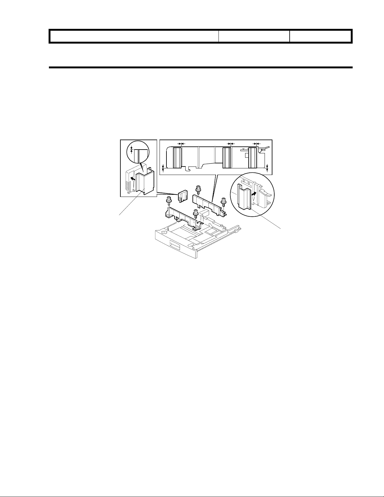
3.1.1 267 mm x 390 mm paper
NAD30/40
Bulletin
Date:
No:
PAGE: 2/14
[B]
[A]
A231I542.WMF
1. Remove the paper tray.
2. Remove the side fences (2 screws each) and the end fence.
3. Peel off the backing of the double-sided tape that is attached to the side fence spacer
(t=7.2 mm) [A].
4. Attach the side fence spacer to the side fence as shown (3 spacers for each side
fence).
NOTE:
5. Peel off the backing of the double-sided tape that is attached to the end fence spacer
(t=31 mm) [B].
6. Attach the end fence spacer to the end fence as shown.
Both edges of the spacer should be aligned with the bottom edge of the fence.
7. Install the side fences in the 11” position in the paper tray.
8. Install the end fence In the A3 position in the paper tray.
9. Install the paper tray in the machine and enter the UP mode.
10. Select the paper size as follows
267 x 390 mm paper = 16
·
Page 3
RICOH Technical
Bulletin
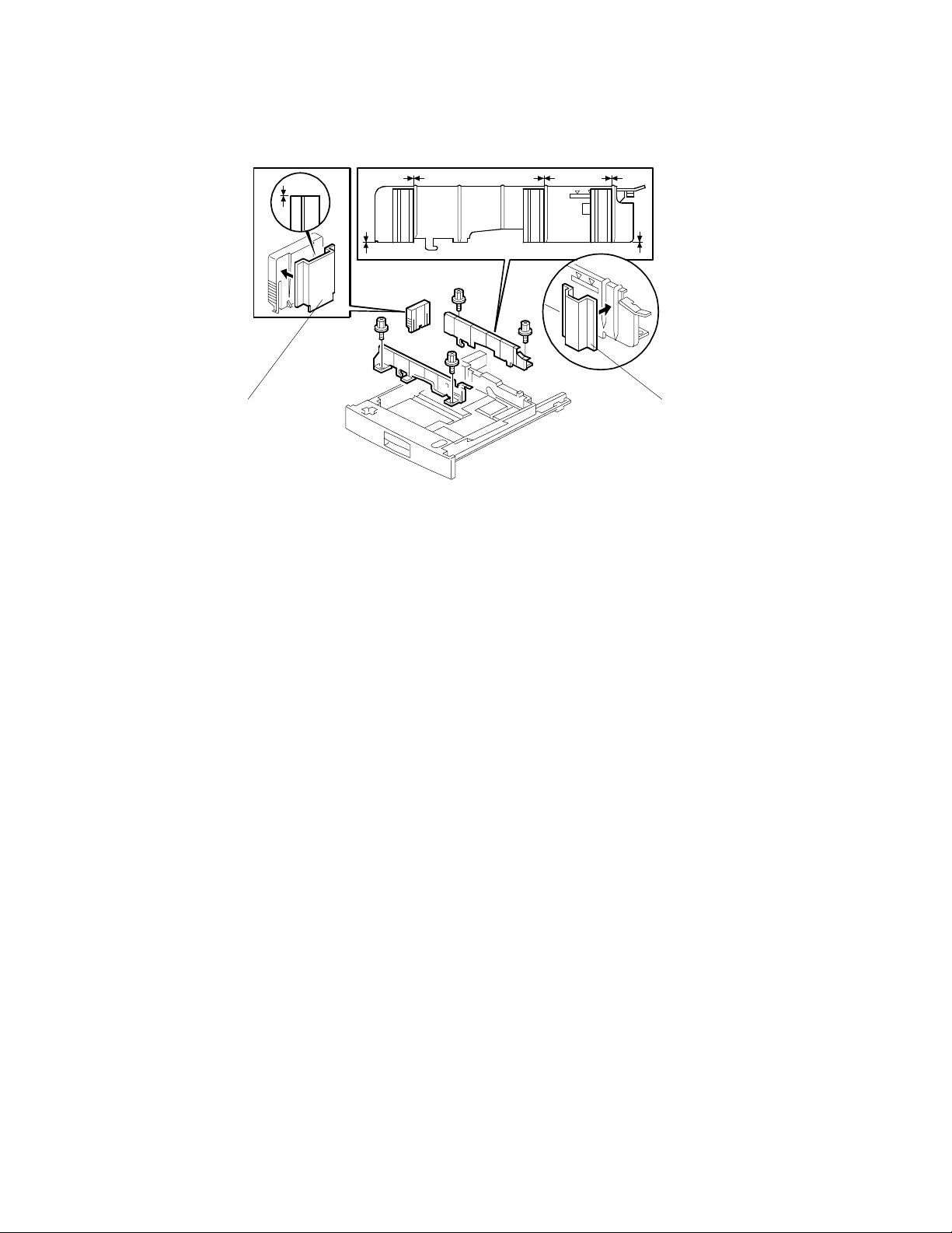
3.1.2 195 mm x 267 mm lengthwise paper
PAGE: 3/14
[A][B]
A231I541.WMF
1. Remove the paper tray.
2. Remove the side fences (2 screws each) and the end fence.
3. Peel off the backing of the double-sided tape that is attached to the side fence spacer
(t=7.2 mm) [A].
4. Attach the side fence spacer to the side fence as shown (3 spacers for each side
fence).
NOTE:
5. Peel off the backing of the double-sided tape that is attached to the end fence spacer
(t=16 mm) [B].
6. Attach the end fence spacer to the end fence as shown.
7. Install the side fences in the 11” position in the paper tray.
8. Install the end fence in the A4Y position in the paper tray.
9. Install the paper tray in the machine and enter the UP mode.
10. Select the paper size as follows
195 x 267 mm paper = 8
·
Both edges of the spacer should be aligned with the bottom edge of the fence.
M
Page 4
RICOH Technical
Bulletin
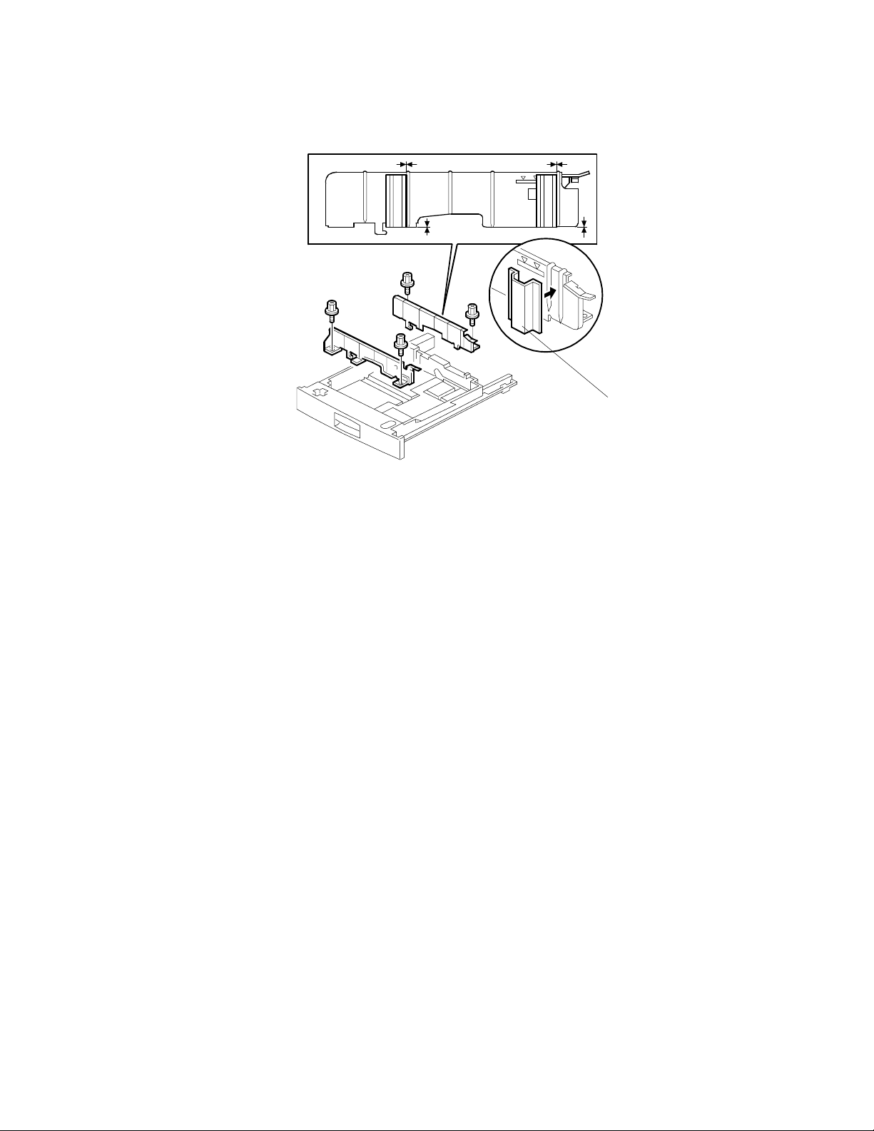
3.1.3 267 mm x 195 mm lengthwise paper
PAGE: 4/14
[A]
A231I540.WMF
1. Remove the paper tray.
2. Remove the side fences (2 screws each) and the end fence.
3. Peel off the backing of the double sided tape that is attached to the side fence spacer
(t=5.1 mm) [A].
4. Attach the side fence spacer to the side-fence as shown (2 spacers for each side
fence).
NOTE:
5. Install the side fences in the 8” position in the paper tray.
6. Install the end fence in the 10.5” position in the paper tray.
7. Install the paper tray in the machine and enter the UP mode.
8. Select the paper size as follows
267 x 195 mm paper = 8
·
Both edges of the spacer should be aligned with the bottom edge of the fence.
L
Page 5
RICOH Technical
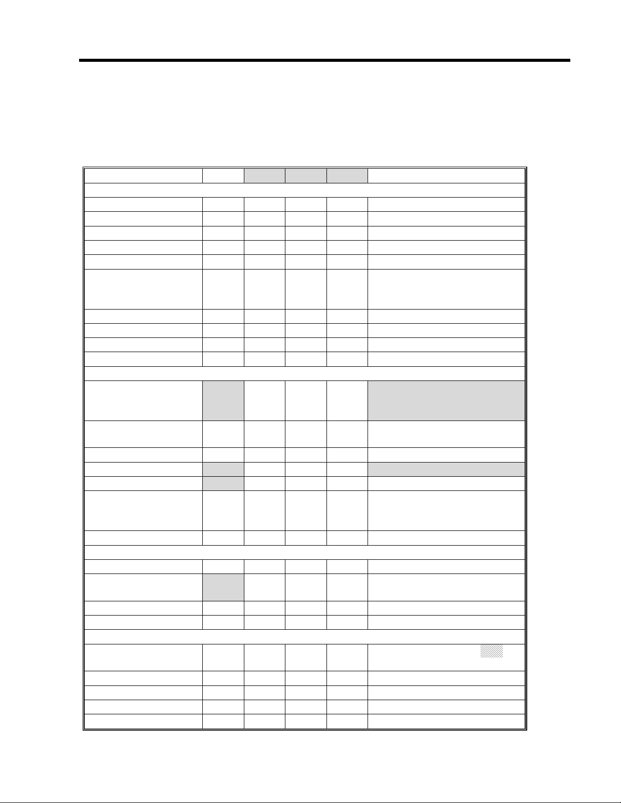
4. SERVICE TABLES
4.1 Service program mode
Mode No.
Class 1
and 2
4-301
Class 3
APS Sensor
Output Check
Displays the APS sensor output
signals when an original is placed on
the exposure glass.
Bit 0: Width sensor 1
Bit 1: Width sensor 2
Bit 2: Length sensor 1
Bit 3: Length sensor 2
Bit 4: Length sensor 3
See “Detailed Section Descriptions –
Original Size Detection in Platen
Mode” for more details.
Bulletin
Function Settings
00000000
0: Not
detected
1: Detected
PAGE: 5/14
4-303
*
4-428* 1* Standard White
APS Small Size
Original Detection
Chinese Paper
Size Detection
Level Adjustment
Flag
Selects whether or not the copier
determines that the original is
A5/HLT size when the APS sensor
does not detect the size.
If "A5 length/5.5" x 8.5" is selected,
paper sizes that cannot be detected
by the APS sensors are regarded as
A5 lengthwise or 5.5" x 8.5".
If "Not detected" is selected, "Cannot
detect original size" will be displayed.
Numbers 2 and 3 are used for Chinese
paper sizes (267 x 390 mm and 195 x 267
mm). The meanings of numbers 2 and 3
are the same as for number 1 and 2.
However, if the APS sensors detect the
original, the machine assumes Chinese
paper sizes.
For example:
A4 ® 195 x 267 mm
A3 ® 267 x 390 mm
Displays whether or not the standard
white level adjustment has been
done.
0: Not
detected
1: A5 length/
5.5" x 8.5"
2: Not detected
(Chinese pap er)
3: A5 length
(Chinese pap er)
0: Performed
1: Not
performed
Page 6

RICOH Technical
Bulletin
4.2 Special Tools and Lubricants
4.2.1 Special tools
Part Number Description Q’ty
A2309003 Adjustment Cam – Laser Unit 1
A2309004 Positioning Pin – Laser Unit 1
A2309352 Flash Memory Card – 4MB 1
A2309351 Case – Flash Memory Card 1
A0069104 Scanner Positioning Pin (4 pcs/set) 1
54209516 Test Chart – OS-A3 (10 pcs/Set) 1
A0299387 Digital Multimeter – FLUKE 87 1
A2309099 NVRAM – Minus Counter 1
A2309600 Side Fence Spacer – 7.2 mm (6 pcs) 1
A2309610 Side Fence Spacer – 5.1 mm (4 pcs) 1
A2309620 End Fence Spacer – 31 mm 1
A2309630 End Fence Spacer – 16 mm 1
PAGE: 6/14
Page 7

RICOH Technical
For the China version
4. SERVICE TABLES
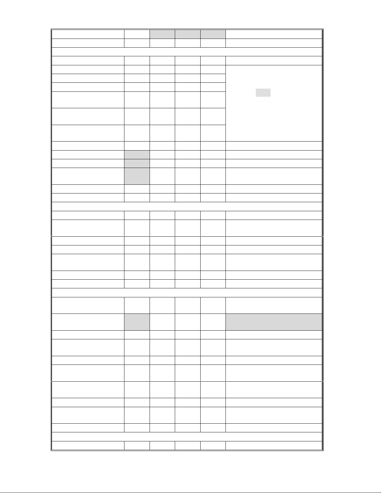
4.1 Service Program Mode
Mode No.
Class 1
and 2
5-401* 82* Restricted Access
Class 3
Control for Key
Counter – Other
Enhanced Kit
Japanese version only.
Do not change the value.
Bulletin
Function Settings
0: No
1: Yes
PAGE: 7/14
83*
5-501 * PM Alarm Interval Sets the PM interval, with an alarm.
5-504* 1*
2*
5-505* Error Alarm Level
Restricted Access
Control for other
counters – Other
Enhanced Kit
Jam Alarm Level
(RSS function)
Jam Auto Call
(RSS function)
Japanese version only.
Do not change the value.
When the setting is "0", this function
is disabled.
For the China version, this value
should be changed to 100k.
Japanese version only.
Do not change the values.
Japanese version only.
Do not change the values.
0: No
1: Yes
0 ~ 255
1k copies/step
150 k copies
0: Z
1: L
2: M
3: H
0: Off
1: On
0 ~ 255
100
copies/step
2500 copies
(30)
5000 copies
(40)
Page 8
RICOH Technical
Bulletin
5. PREVENTIVE MAINTENANCE SCHEDULE
5.1 PM TABLE
NOTE:
Symbol key: C: Clean, R: Replace, L: Lubricate, I: Inspect
The amounts mentioned as the PM interval indicate the number of prints.
PAGE: 8/14
A230/A231/A232 EM
SCANNER/OPTICS
Reflector C C C Optics cloth
1st Mirror C C C Optics cloth
2nd Mirror C C C Optics cloth
3rd Mirror C C C Optics cloth
Scanner Guide Rails I I I Do not use alcohol.
Platen Sheet Cover C I I I
Exposure Glass C C C Dry cloth or alcohol
Toner Shield Glass C C C Optics cloth
APS Sensor C C C Dry cloth or alcohol
AROUND THE DRUM
Charge Roller
Charge Roller
Cleaning Pad
Quenching Lamp C Dry cloth
Pick-off Pawls
Spur
ID Sensor C C C
C
C
C
100K 200K 300K
Replace the platen sheet, if
necessary.
Dry cloth or alcohol
RRR
R R R Dry cloth
RRR
C C C Dry cloth or alcohol
Clean with alcohol. After
cleaning, dry the roller with a
dry cloth.
Dry cloth
Perform the ID sensor initial
setting (SP3-001-2) after
cleaning (blower brush)
NOTE
CLEANING UNIT
Drum Cleaning Blade R R R
Cleaning Entrance
Seal
Side Seal I I I
DEVELOPMENT UNIT
Development Drive
Gears
Development Filter R
Developer I R I
Entrance Seal I I I
Side Seal I I I
C
C C C Blower brush or dry cloth.
III
Replace if necessary.
Replace every 5 PM
(
500k)
Page 9
RICOH Technical
Bulletin
PAGE: 9/14
A230/A231/A232 EM
PAPER FEED
Registration Roller C C C C Clean with water or alcohol.
Paper Feed Roller I R R R
Separation Roller I R R R
Pick-up Roller I R R R
Paper Feed Roller
(By-pass feed table)
Separation Roller
(By-pass feed table)
Pick-up Roller
(By-pass feed table)
Paper Feed Guides C C C Clean with water or alcohol.
Relay Rollers
Bottom Plate Pad
Bottom Plate Pad
(By-pass feed)
Registration Sensor C C C Blower brush
TRANSFER BELT UNIT
Transfer Belt C R R R Dr y cloth
Transfer Belt
Cleaning Blade
Transfer Belt Rollers C C C Dry cloth
Entrance Seal C C C Dry cloth
Transfer Entrance
Guide
Used Toner Tank I C C C Empty the tank.
C
C
C
CCCCDry cloth
100K 200K 300K
Check the counter value for
each paper tray station (SP7-
204). If the value has
IRRR
IRRR
IRRR
C C C Clean with water or alcohol.
C C C Clean with water or alcohol.
C C C Clean with water or alcohol.
RRR
reached
roller. After replacing the
roller, reset the counter (SP7-
816).
NOTE
100k, replace the
FUSING UNIT AND PAPER EXIT
Fusing Entrance and
Exit Guide Plates
Hot Roller
Pressure Roller R R R
Fusing Thermistor I I I Clean if necessary (suitable
Cleaning Roller C C C Clean with water or alcohol.
Cleaning Roller
Bushings
Pressure Roller
Strippers
Hot Roller Strippers C R C Clean wit h water or alcohol.
Paper Exit Guide
Ribs
OTHERS
Drive Belts I Replace if necessary
C
C C C Clean with water or alcohol.
RRR
L L L Grease Barrierta JFE 55/2
C C C Clean with water or alcohol.
C C C Clean with water or alcohol.
Clean with alcohol (or a suitable
solvent)
solvent)
Page 10
RICOH Technical
EM 80K 160K 240K NOTE
ADF
(for origina ls)
Transport Belt C R R R Belt cleaner
Feed Belt C R R R Belt cleaner
Separation Roller C R R R Dry or damp cloth
Sensors C C C Blower brush
Drive Gears L L L Grease G501
Bulletin
PAGE: 10/14
EM
PAPER TRAY UNIT
Paper Feed Rollers
Pick-up Rollers
Separation Rollers
Relay Rollers C C C Dry or damp cloth
Bottom Plate Pad
LCT
Paper Feed Roller
Pick-up Roller
Separation Roller
Bottom Plate Pad
C
EM
C
100K 200K 300K
I
I
I
I
I
I
RRR
RRR
RRR
C C C Dry or damp cloth
100K 200K 300K
RRR
RRR
RRR
C C C Dry or damp cloth
Check the counter value for
each paper tray station (SP7-
204). If the value has reached
100k, replace the roller. After
replacing the roller, reset the
counter (SP7-816).
Check the counter value for
each paper tray station (SP7-
204). If the value has reached
100k, replace the roller. After
replacing the roller, reset the
counter (SP7-816).
NOTE
NOTE
EM
1,000-SHEET/3,000-SHEET FINISHERS
Rollers C Clean with water or alcohol.
Brush Roller I I I I Replace if necessary.
Discharge Brush C C C C Clean with a dry cloth
Sensors C Blower brush
Jogger Fences I I I I Replace if necessary.
Punch Waste Hopper I I I I Empty the hopper.
EM
1-BIN TRAY UNIT
Rollers C Dry or damp cloth
Copy Tray C Dry or damp cloth
Sensors C Blower brush
100K 200K 300K
100K 200K 300K
NOTE
NOTE
Page 11
RICOH Technical
Bulletin
PAGE: 11/14
5.2 Maintenance Items for the China Version
Using Chinese paper, paper dust may accumulate inside the machine during copying.
After the machine has been used for a long time, some copy quality or mechanical
problems may occur. So, do the following to maintain the machine’s quality.
1. PM interval
Every 100,000 copies
NOTE:
2. At the PM and EM period, change the PM parts and/or clean the parts in accordance
with the PM table. Especially, the following should be done.
Around the Drum
Charge Roller Replace Clean
Pick-off Pawls Replace Clean Clean with a dry cloth. B
Spurs Clean Clean Clean with a dry cloth. C
PCU Entrance
Seal
ID Sensor Clean Clean
Cleaning Unit
Cleaning
Entrance Seal
Paper Feed
Relay Rollers Clean Clean Clean with water or alcohol.
Registration
Roller
Bottom Plate
Pad
Fusing Unit
Hot roller Replace Clean Clean with alcohol ( or a
At the machine installation, change the value of SP5-501 (PM alarm interval)
to 100 k.
PM EM Action Problem Fig.
Clean with alcohol. After
cleaning, dry the roller with
a dry cloth.
Clean Clean Clean with a dry cloth
Clean with a dry cloth. After
cleaning perform, SP3001-
2.
Clean Clean Clean with dry cloth Toner falls onto
Clean Clean Clean with water or alcohol. G
Clean Clean Clean with water or alcohol.
suitable solvent).
Dirty background
on front and rear
of paper
Toner falls onto
the paper.
the paper.
Paper non feed or
paper double
feed
Offset image
A
F
E
D
Page 12

RICOH Technical
[A]
[B]
Bulletin
PAGE: 12/14
[C]
1. Pull out the PCU, then clean the following parts.
ID Sensor [E]
·
PCU Entrance Seal [F]
·
Registration Roller [G]
·
2. Remove the drum, then clean the following parts.
Charge Roller [A]
·
Pick-off Pawls [B]
·
Spurs [C]
·
Cleaning Entrance Seal [D]
·
[D]
A231P501.WMF
[E]
[F]
[G]
A231P500.WMF
Page 13

RICOH Technical
Model:
NAD30/40
Bulletin
Date:
Taiwan Version
1. Overall Machine Information
5.3 Specifications
Power Consumption:
Mainframe only
(115 V Machine)
NAD30S/NAD30 NAD40 Note
Maximum
Copying Less than 1.15 kW
Warm-up Less than 1.05 kW Less than 1.15 kW
Stand-by Less than 200 W/h Less than 220 W/h
Energy Saver Level 1 Ave. 150 W/h Ave. 170 W/h
Energy Saver Level 2 Ave. 130 W/h Ave. 150 W/h
Auto Shut Off Ave. 12 W/h Ave. 12 W/h
Less than 1.44 kW Less than 1.44 kW
Less than 1.32 kW Less than 1.32 kW Taiwan version
Less than 1.3 kW
Less than 1.25 kW Taiwan version
PAGE: 13/14
No:
System: Without the optional heater s, fax unit, and printer controller.
(115 V machine)
NAD30S/NAD30 NAD40 Note
Maximum
Copying Less than 1.2 kW Less than 1.35 kW
Warm-up Less than 1.05 kW Less than 1.15 kW
Stand-by Less than 220 W/h Less than 260 W/h
Less than 1.44 kW Less than 1.44 kW
Less than 1.32 kW Less than 1.32 kW Taiwan version
Page 14

RICOH Technical
Bulletin
5.4 Machine configuration
Version Item Machine Code No.
Copier (NAD30-S) A230 8
Copier (NAD30) A231 8
Copier (NAD40) A232 8
ARDF (Option) A680 2
Platen Cover (Option) A381 1
Paper Tray Unit (Option) A682 9
LCT (Option) A683 7
By-pass Feed Unit (Option – NAD30S only) A689 5
Duplex Unit (Option – NAD30S only) A687 6
Interchange Unit (Option – NAD30S only) A690 4
Copy
Fax
1-bin Tray (Option) A684 3
Bridge Unit (Option) A688 13
1000-sheet Finisher (Option) A681 11
3000-sheet Finisher (Option – NAD40 only) A697 10
Punch Unit (Option for 3000-sheet Finisher) A812-17 (3 holes)
A812-27 (2 holes)
External Output Tray (Option) A825 12
Electrical Sort Kit – 8 MB Memory (Option –
NAD30S only)
Image Enhancement Kit – HDD (Option)
Key Counter Bracket (Option) A674 14
Expansion Box (Option) A692
Fax Unit (Option) A693
ISDN Unit (Option) A816
SAF Memory – HDD (Option) A818-10
Fax Feature Expander (Option) A818-11
400-dpi High Resolution (Option) A818-12
Handset (Option – North America only) A646
Stamp Unit (Option) A813
NOTE
*
A818
A691
PAGE: 14/14
*NOTE:
For the Taiwan version, this kit will be available when the optional printer unit
is installed.
Page 15

RICOH Technical
Model:
NAD 30S/30/40
Bulletin
Date:
31-May-98
No:
PAGE: 1/5
2
Subject:
From:
Service Manual Corrections
Technical Service Department.
Classification:
Troubleshooting
Mechanical
Paper path
Other (Manual Correction)
Part information
Electrical
Transmit/receive
Prepared by:
Action required
Service manual revision
Retrofit information
S. Tomoe
The following should be corrected. Please correct your service manual.
1. 2.2.5 MEMORY BLOCK page 2-19
- Incorrect -
Copy Mode
Multiple copy of
single page original
Gradation
Processing
Binary/Grayscale
DRAM
(4 MB)
O / O
DRAM + SIMM
(4 + 8 MB)
O / O X / O
DRAM + SIMM + HDD
- Correct -
Copy Mode
Gradation
Processing
DRAM
(4 MB)
DRAM + SIMM
(4 + 8 MB)
DRAM + SIMM + HDD
(12 MB + 1.6GB)
(12 MB + 1.6GB)
Multiple copy of
single page original
Binary/Grayscale
O / X
O / O X / O
2. 2.6.7 TONER NEAR END/END DETECTION Page 2-44
Second paragraph from the bottom
- Incorrect If Vsp is
However, If Vsp is
less
than 2.0V, the density of the ID sensor pattern is very light, so ……
bigger
than 2.0V but 90 copies have been made after toner near end
was detected,….
- Correct If Vsp is
However, If Vsp is
bigger
than 2.0V, the density of the ID sensor pattern is very light, so ……
less
than 2.0V but 90 copies have been ma de a fter toner near end
was detected,….
Page 16

RICOH Technical
Model:
3. 2.10.3 FUSING ENTRANCE GUIDE SHIFT MECHANISM page 2-66
Second and third paragraphs
NAD 30S/30/40
- Incorrect -
Bulletin
Date:
31-May-98
No:
PAGE: 2/5
2
For thin paper, move the entrance guide to the
For thick paper, move the entrance guide to the
- Correct For thin paper, move the entrance guide to the
For thick paper, move the entrance guide to the
4. 3.1.4 POWER REQUIRMENTS page 3-3
- Incorrect Input voltage level: 220V ~ 240V, 50 Hz/60 Hz: More than 6A
- Correct Input voltage level: 220V ~ 240V, 50 Hz/60 Hz: More than 8A
5. 3.3.1 ACCESSORY CHECK page 3-5
- Incorrect -
Operation Instructions – Fax Reference
12.
left
by securing it with screw holes [C].
right
(using screw holes [B]).
right
by securing it with screw holes [B].
left
(using screw holes [C]).
- Correct -
Copy Quick Guide
12.
6. 3.12 1000-SHEET FINISHER INSTALLATION page 3-46
Delete step 5 and modify illustration A230I704.wmf (see the attached illustration).
·
Add the following step after step 13 on page 3-47 and modify illustration
·
A230i706.wmf (see the attached illustration).
14. Attach the staple position decal [F] to the ARDF, as shown.
Page 17

RICOH Technical
Bulletin
7. 3.13 3000-SHEET FINISHER INSTALLATION page 3-48
Change the step from 5 to 8
·
- Incorrect -
PAGE: 3/5
5. Attach
Cut away a part of the main power switch cover [E].
6.
two
lower grounding plates …..
7. Attach the cushion [F] to the plate as shown.
8. Install the entrance guide plate [G] (2 screws).
- Correct -
5. Attach
one
lower grounding plate ……
6. Attach the cushion [E] to the plate as shown.
7. Install the entrance guide plate [F] (2 screws).
Change illustrations A230I754.wmf and A230I755.wmf.
·
8. 3.18 KEY COUNTER INSTALLATION page 3-62
Add step 11.
11. Change the value of SP5-401-2 to 1.
NOTE:
The key counter function is availabl e for fax and printer mod es by chang ing the
following SP modes.
SP5-401-52 (Fax mode)
SP5-401-62 (Printer mode)
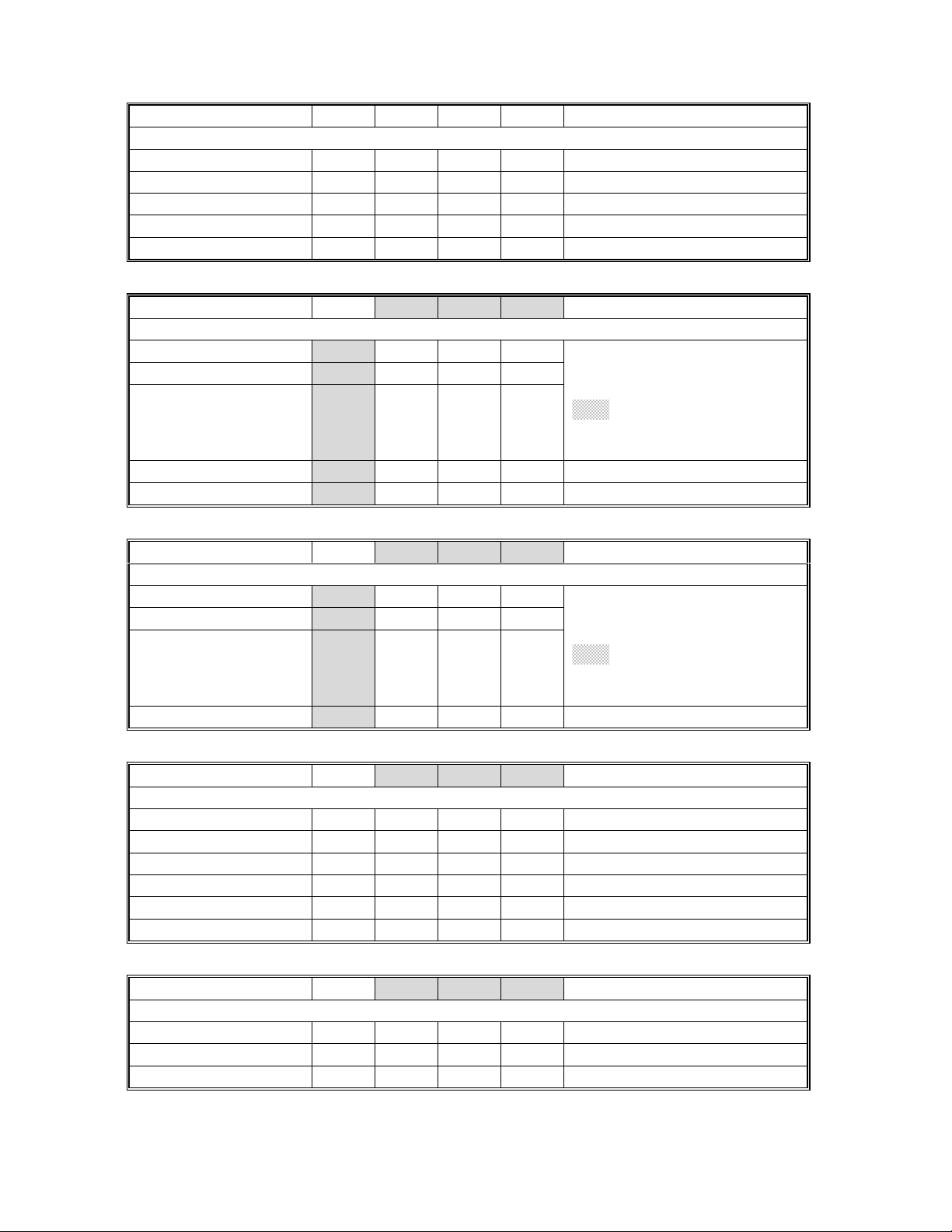
9. 4.4.2 SERVICE PROGRAM MODE TABLE page 4-10
- Incorrect -
Mode No.
Class 1
and 2
2-101
Class 3
3 *
4 *
Left
Side
Edge Erase
Margin
(Printing)
Right
Side
Edge Erase
Margin
(Printing)
Adjusts the
The specification is 2
Adjusts the
The specification is 2 + 2.5/- 1.5 mm
Function Setting
left
side erase margin.
±
1.5 mm
±
right
side erase margin.
0.0 ~ 9.0
0.1 mm/step
2.0 mm
0.0 ~ 9.0
0.1 mm/step
2.0 mm
Page 18

RICOH Technical
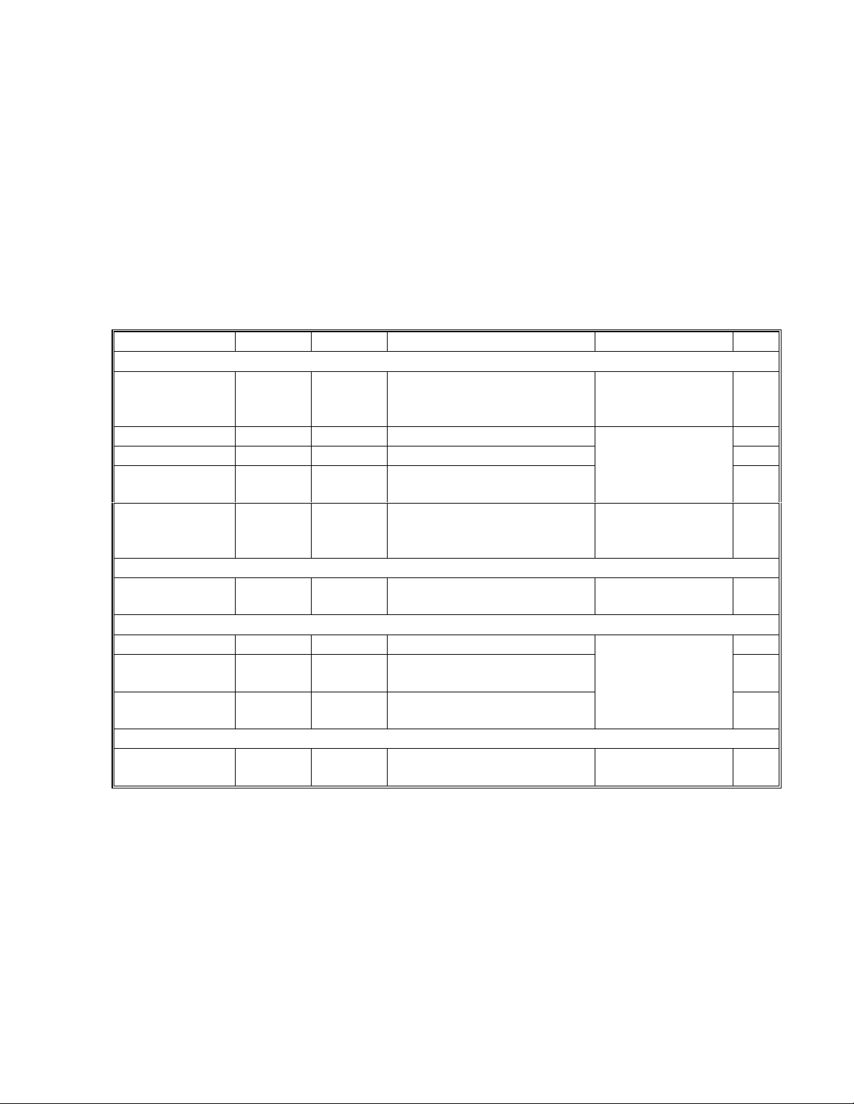
- Correct -
Mode No.
Class 1
and 2
Class 3
Bulletin
Function Setting
PAGE: 4/5
2-101
3 *
4 *
Right
Side
Edge Erase
Margin
(Printing)
Left
Side
Edge Erase
Margin
(Printing)
Adjusts the
The specification is 2 + 2.5/- 1.5 mm
Adjusts the
The specification is 2
right
side erase margin.
left
side erase margin.
±
1.5 mm
±
0.0 ~ 9.0
0.1 mm/step
2.0 mm
0.0 ~ 9.0
0.1 mm/step
2.0 mm
10. Laser Beam Pitch Adjustment page 6-18
- Incorrect -
8. Adjust the laser beam pitch position …. Appear on the printout), doing steps
and 3 (in step 1, input a value which is estimated to be correct, then steps 2 and 3,
then if necessary go back to step 1 and try another value).
9. After adjusting the laser beam pitch ….. (….for 600 dpi).
The laser beam pitch for
600 dpi should be 24 ~ 48 more than for 400 dpi.
- Correct -
8. Adjust the laser beam pitch position …. Appear on the printout), doing steps
and 4 (in step 2, input a value which is estimated to be correct, then steps 3 and 4,
then if necessary go back to step 2 and try another value).
1, 2
2, 3
,
,
9. After adjusting the laser beam pitch ….. (….for 600 dpi).
adjustment for 600 dpi, input a value for SP2-109-1 that is between 24 and 48
higher than the final result for 400 dpi.
11. Blank Margin page 6-52
- Incorrect -
SP mode Specification
Right edge
Left edge
SP2-101SP2-101-
4
3
- Correct -
SP mode Specification
Right edge
Left edge
SP2-101SP2-101-
3
4
When starting the
2 +2.5/-1.5 mm
2 ± 1.5 mm
2 +2.5/-1.5 mm
2 ± 1.5 mm
Page 19

RICOH Technical
12. SC630 page 7-18
The SC condition level, [D], should be added.
Bulletin
PAGE: 5/5
SC630: CSS (RSS) communication error between line adapter and CSS center
13. Illustrations
[E]
[A]
[B]
[C]
[C]
A230i704.wmf A230i706.wmf
[D]
[A]
[D]
[F]
[C]
[A]
[E]
[F]
[D]
A230i754.wmf A230i755.wmf
Page 20

RICOH Technical
Model:
NAD 30S/30/40
Bulletin
Date:
31-May-98
No:
PAGE: 1/6
3
Subject:
From:
Classification:
This bulletin contains corrections for the Fax Option Type 450 service manual.
Service Manual Corrections
Technical Service Department.
Troubleshooting
Mechanical
Paper path
Other ( )
Part information
Electrical
Transmit/receive
Prepared by:
Action required
Service manual revision
Retrofit information
Y. Furuya
Chapter 3
Problem
1) The installation procedure was not suitable for the Taiwan version
2) A bracket must be removed before installing the expansion box; this was not
mentioned.
3) The procedure for attaching the PTT approval label was missing.
Correction
1) The installation procedure has been modified for all versions, including Taiwan.
2) Missing steps have been added. (Items 2 and 3 above; refer to pages 2 to 5.)
Page 21

RICOH Technical
Bulletin
PAGE: 2/6
NOTE:
[A]
To install the fax unit, the Expansion Box Type 450 is required in addition.
The following procedure is written on the premise that the expansion box
has not been installed.
[C]
[D]
[B]
A693I500.WMF
[I][J]
[I]
[F]
A693I501.WMF
[M]
[F]
[E]
[L]
[K]
[H]
A693I519.WMF
1. Remove the rear cover [A] (4 screws) and the left side cover [B] (4 screws), as shown.
2. Cut away the covers [C] and [D] (shaded parts), as shown.
NOTE:
3. Remove the cover [E] from the expansion box, then install the FCU cover bracket [F]
(1 screw) as shown.
NOTE:
4. Remove the bracket [G], and run the cable [H] through the clamps [I], then install a
metal core [J] as shown.
NOTE:
5. Connect the harness [K] to CN355 on the expansion box, then install the expansion
box (4 screws) so that the CN350 fits in CN304 [L] on the BiCU.
NOTE:
If installing the fax hard disk option at the same time, refer to the hard
disk installation procedure before going on to the next step.
The bracket [F] is included in the fax unit.
The metal core [J] is not installed the model for Taiwan.
Use a magnetic screwdriver so as not to drop any screws inside the
machine.
A693I503.WMF
6. Attach the modular jacks [M] to the bracket [F] as indicated on the bracket.
Page 22

RICOH Technical
[N]
[P]
Bulletin
PAGE: 3/6
[Q]
[O]
[U]
[S]
A693I504.WMF
[R]
A693I514.WMF
[R]
[O]
[T]
A693I505.WMF
[V]
A693I515.WMF
7. Set the locking support [N] and the edge saddle [O] as shown, then install the
NCU/Speaker assembly [P] (2 screws).
8. Connect the cable [Q] and the harness [R] as shown. The harness [R] must run
through the edge saddle [O] as shown.
9. Turn on the battery switch (SW1) on the FCU [S] then set it in the right-most slot of the
expansion box as shown. Connect the harness [R] to the FCU (CN328 and CN330),
then slide the FCU [S] all the way in (1 connector).
10. Install the brackets [T] (3 screws), [U] (2 screws) and [V] (1 screw) as shown.
NOTE:
The bracket [U] is installed only in the model for Taiwan.
Page 23

RICOH Technical
Bulletin
PAGE: 4/6
[X]
[Y]
[d]
[Z]
A693I507.WMF
[a]
[W]
[c]
[b]
A693I508.WMF
[e]
[g]
[i]
[W]
[f]
A693I509.WMF
11. Remove the operation panel [W], then remove parts [X], [Y],
and [Z].
12. Install part [a], then connect the harnesses [b] and [c] to the
operation panel as shown.
13. Replace the operation panel [W], then install the parts [d] and
[e], as shown.
14. Replace the left side cover (4 screws) and the rear cover (4
screws).
15. Affix the serial number label [f], the LINE/TEL label [g] and the
appropriate approval label [h] onto the rear cover. Then install
the bracket [i] (1 screw).
16. Attach the “Super G3” label [j] to the front cover.
[h]
A693I516.WMF
[j]
A693I511.WMF
Page 24

RICOH Technical
[k]
17. Wrap the phone line around the core [k] as shown, and connect it to the “LINE” jack at
the rear of the machine.
18. Plug in the machine and turn on the main power switch.
19. Press the ‘Facsimile’ key and check the facsimile LED lights.
At this time, the display reads: SC1201 - Functional problem with the fax. Data should
be initialized.
NOTE:
This is not a functional problem. The machine shows this message only
when the fax unit is first installed. If the same message appears at the
next power-on, check whether the battery switch (SW1) on the FCU
has been turned on.
Bulletin
A693I517.WMF
PAGE: 5/6
20. Press “Yes” to initialize the fax unit.
21. Set up and program the items required for fax communications as shown below. If the
user function keys (F1, F2, F3, F4, and F5) need to be programmed, attach the label.
The default settings of the user function keys are as follows:
F1: Start Manual Rx
·
F2: Tx Result Display
·
F3: TEL Mode
·
F4: Not programmed
·
F5: Not programmed
·
NOTE:
Program the serial number into the fax unit (service function 10). The serial number can be
found on the serial number label (attached to the machine in step 15).
Be sure to set the clock (date and time).
Page 25

RICOH Technical
Bulletin
PAGE: 6/6
Chapter 4
4.5 Service RAM Addresses
Two addresses are mentioned for the Rx counter, 4801C4 - 4801C6 (H) and 480A64 480A67 (H). This is not correct. 480A64 - 480A67 (H) is the correct address range.
Chapter 5
Section 5.4.1 (Page 5-7)
Problem
SW3 on the FCU MUST BE TURNED OFF
memory card, but the manual does not explain this.
If SW3 is kept on at power-up, the fax application will not start without a 'master' flash
memory card connected.
after downloading firmware from a flash
Correction
Insert the underlined step after step 8 on page 5-7 as shown below.
8. Turn off the main power switch then disconnect the flash memory card.
9. Turn OFF (lower position) SW3 below the card slot.
10. Turn the machine back on.
RC RE ASIA
Page 26

T
Model:
NAD 30S/30/40
echnical
B
ulletin
Date:
31-May-98
No:
PAGE: 1/3
4
Subject:
From:
Software Release Information
Technical Service Department.
Classification:
Troubleshooting
Mechanical
Paper path
Other ( )
Part information
Electrical
Transmit/receive
Prepared by:
Action required
Service manual revision
Retrofit information
This RTB shows the software release information for the BICU board.
April 1998
PCB Part Number: A2325051K (BICU board – 115V)
A2325052K (BICU board – 230V)
A2325053C (BICU board – Asia)
Software Version: 13.1.8
Program Number: A2325113E (NA)
A2325114E (EU)
A2325115B (Asia)
Effective date: From first production of April 1998
S.Tomoe
Spec.
No. Function Details
When doing initial SP settings such as
1
TD sensor initialization during
warming-up, SC542 will occur.
If entering the following SP mode
during warming-up, the beeper
sounds twice and the operation is
canceled.
Related SP mode:
SP2207
SP2801
SP2805
SP3001-2
Problems
No. Title Details
The machine may stall when making a
1
combined copy, after printing the
archive file list.
The “ Menu” key LED stays on even if
2.
copy job is finished.
When pr essing “ +” after i nputting
3.
400% with the Zoom key, “*
maximum” is displayed. If this
This happens when an archive file list
is printed with double sided copying,
but one side does not have any
archive files. Then, the machine
makes a combine mode copy with one
part blank.
This happens when selecting the
Original Mode in the Menu mode and
selecting the staple mode.
Page 27

T
No. Title Details
condition continues until the auto
reset time, SC990 may occur.
When the HDD is defective and the
4
main power switch is turned on, the
machine does not go to an SC
condition but it may stall.
The description of SP 5803-6 has
5.
been corrected.
Archive file malfunction When an original is stored as an
6
The memory is cleared automatically,
7
three seconds just after entering
SP5801.
The description of SP2213 does not fit
8
in the display.
-17 only
9.
The paper size determined when the
machine detects a non-standard
original size has been changed.
echnical
By-pass Paper Set Sensor
Unit Set Detection
archive file, two archive files will be
made.
The memory should be cleared as
follows.
1. Enter SP5801
2. Hold down the “1” for over 3 s.
B
ulletin
PAGE: 2/3
Æ
2. May 1998
PCB part number: A2325051M (BICU board – 115V)
A2325052M (BICU board – 230V)
A2325053E (BICU board – Asia)
Software Version: 13.6.3
Program Number: A2325113G (NA)
A2325114G (EU)
A2325115D (Asia)
Effective date: Form first production of May, 1998
Spec.
No. Function
1 When A3 or B4 paper size is selected in the rotate sort (or stack) mode, the
machine can now copy with normal sort (or stack) mode.
2 Theh electrical total counter value of brand new machines has been changed
from -2000 to –5000.
3 During multiple copying and with no HDD option installed, the machine can
scan an original for fax transmission.
4 The copy quality for light original mode has been improved. The gamma curve
value for the original mode has been changed.
5 SC900-01 will be generated when the mechanical counter is disconnected.
Page 28

T
Problem
No. Title Details
NAD40 only:
1
To improve the copy quality (Medaka
image), the default values of the
following SP modes have been
changed.
SP2001-1: 1650V Æ 1620V
SP2005-3: 1650V Æ 1620V
2. The machine sometimes does not
reach the stand-by mode condition
after the main switches are turned on
or after clearing a jam. This is
because the machine cannot detect
the zero cross signal.
3. When changing the value of SP6105
(staple position adjustment) and
SP6113 (punch hole position
adjustment) to a negative value, then
turning the main switch off and on, the
machine does not send the SP setting
to the finisher.
4 If the electrical counter value is a
negative value, the counters for the
fax option do not increment.
echnical
Countermeasure:
1. If the zero cross signal is not
detected after main power switch is
turned on, SC 547 will occur.
2. If the zero cross signal is not
detected after operation switch is
turned on, SC 542 will occur.
B
ulletin
PAGE: 3/3
NOTE:
The following software versions were released. However, soon after release, the next
version was released. So, the following software version has never been used.
PCB Part number: A2325051L (BICU board – 115V)
A2325052L (BICU board – 230V)
A2325053D (BICU board – Asia)
Software Version: 13.6.1
Program Number: A2325113F (NA)
A2325114F (EU)
A2325115C (Asia)
Page 29

T
Model:
NAD 30S/30/40
echnical
B
ulletin
Date:
15-Jun-98
No:
PAGE: 1/1
5
Subject:
From:
Classification:
The US government version NAD will be produced in Japan, and the standard version in
China. Accordingly, some parts used in the government version are different from the
standard version. This RTB will introduce the machine codes for the government version
and the different parts.
1. Machine Code and Model Name
Government Version Information
Technical Service Department
Troubleshooting
Mechanical
Paper path
Other ( )
Brand Ricoh Gestetner/Savin
Machine Code A230-37 A231-37 A232-37 A230-30 A231-30 A232-30
Model Name Aficio 340 Aficio 350 Aficio 450 G : 3235S
Part information
Electrical
Transmit/receive
Prepared by:
Action required
Service manual revision
Retrofit information
S: 9935D
S.Tomoe
G: 3235
S: 9935DP
G: 3245
S: 9945DP
2. Parts Information
The following are the unique parts for the government version.
Parts Number Description Index No. Page
AX400077 DC Motor – 3W 18 59
AZ230074 Power Suppl y Unit – 115V 14 61
A2321289 Lower Rear Cover 16 13
G0201964 Mirror 16 23
NOTE:
The above parts, except for the mirror, are interchangeable with those parts for the
standard US version of the machine. If the above mirror is replaced with the standard
version’s mirror (P/N: AC030115), the laser beam pitch adjustment must be
performed.
Page 30

T
Model:
NAD 30S/30/40 (1000-sheet Finisher)
echnical
B
ulletin
Date:
30-Jun-98
No:
PAGE: 1/2
6
Subject:
From:
Classification:
Paper rolled up on the shift tray
QAC Field Information Dept.
Troubleshooting
Mechanical
Paper path
Other ( )
Part information
Electrical
Transmit/receive
Prepared by:
Action required
Service manual revision
Retrofit information
M.Mimura
SYMPTOM
When a large number of sheets, such as thirty, are stapled in the multiple copy mode, a
couple of the bottom sheets in the stapled stack may be rolled up on the shift tray.
CAUSE
If the paper facedown-curls excessively, the stapled set of paper will not slide back all the
way to the extreme right position on the shift tray. If this happens, the lower leading edge
of the next set may catch on the trailing edge of the set already on the tray, causing a
couple of the bottom sheets to roll up.
This symptom could occur with a thick stapled set when the copies have piled up high on
the tray. Heavy paper sets will generate stronger friction with the paper set underneath,
and as the copies pile up, the angle of the top copies will level off and make sliding back
more difficult.
Note
: 1. Non-staple mode copies will not exhibit this symptom because single sheets of
paper are delivered to the shift tray at a time.
2. Due to the nature of the copy job type in which this problem occurs, this symptom
would more likely occur with heavy volume users such as copy shops, rather
than with casual users.
SOLUTION
1 The copy paper has a characteristic that one side creates more curl than the other
side. Therefore, instruct the customer to flip over the paper in the paper tray to reduce
the amount of paper curl.
For those customers who have a wide selection of paper brands, recommending a
paper brand which creates less curl might be more beneficial for the customer. (See
page 23 of the Copy Reference manual for related remarks.)
2 This symptom may occur more with A4/11” x 8.5” sideways feed. This is because the
paper can slide up the tray further than other paper sizes. (Larger sizes of paper will
not go that far because of the friction with the lower set of copies.)
If that is the case, install the new version ROM (#A6815103E). The new version ROM
decreases the exit speed of A4/11” x 8.5” sideways paper to drop the paper close to
the right frame for easy switch back. (This happens for stapling more than 11 sheets.)
Page 31

T
Model:
Cut-in Serial Numbers
The new version ROM will be implemented into the production from July ’98. The cut-in
serial numbers are as follows:
Code Brand Cut-in Serial #s
-15 GES. US / SAVIN 1B48070001
-17 RICOH A7728070001
-22 NRG AR2807000
-26 INFOTEC 3R0780001
-55 LANIER From 1st Production
NAD 30S/30/40 (1000-sheet Finisher)
echnical
B
ulletin
Date:
30-Jun-98
No:
PAGE: 2/2
6
Page 32

T
Model:
NAD 30S/30/40 (3000-sheet Finisher)
echnical
B
ulletin
Date:
30-Jun-98
No:
PAGE: 1/2
7
Subject:
From:
Classification:
Paper rolled-up on the shift tray
QAC Field Information Dept.
Troubleshooting
Mechanical
Paper path
Other ( )
Part information
Electrical
Transmit/receive
Prepared by:
Action required
Service manual revision
Retrofit information
M.Mimura
SYMPTOM
When a large number of sheets, such as fifty, are stapled in the multiple copy mod e, a
couple of the bottom sheets in the stapled stack may be rolled up on the shift tray.
CAUSE
The leading edge of the stapled set of paper tends to hang down when fed out onto the
shift tray. If there is an excessive facedown curl at the leading edge, it may catch on the
backside of the prior stack and become rolled up.
This is more evident with thick stapled sets because the curl of the upper paper will press
against the lower paper and this exaggerates the curl.
Note
: 1. Non-staple mode copies will not exhibit this symptom as single she ets of paper
are delivered to the shift tray one at a time.
2. Due to the nature of the copy job in which this problem occurs, this symptom
would more likely occur with heavy volume users, such as copy shops, rather
than with casual users.
SOLUTION
1 The copy paper has a characteristic that one side creates more curl than the other
side. Therefore, instruct the customer to flip over the paper in the paper tray to reduce
the amount of paper curl.
For those customers who have a wide selection of paper brands, recommending a
paper brand which creates less curl might be more beneficial for the customer. (See
page 23 of the Copy Reference manual for related remarks.)
2 Install the new version ROM (#A6975156B). The new version ROM is different from
the current ROM in the following ways:
2.1 After the shift tray has moved from its stand-by position to the upper position, it
will start moving down 50 ms after the paper stack has actuated the finisher exit
sensor. Thus, the paper stack makes a “soft landing” on the shift tray, reducing
the chances of the paper being rolled up.
2.2 The finisher exit roller speed has been increased from 600 to 700 mm/s which
matches that of the stack exit. This will prevent th e leading edge from receiving
the pressure which may encourage the face-down curl.
Note
: The statement in the Service Manual (page # A697-12) that “The speed of the
exit roller is higher than the stack feed-out belt speed.” is wrong.
Page 33

T
Model:
NAD 30S/30/40 (3000-sheet Finisher)
2.3 The mode in which the shift tray receives the stapled copies at its stand-by
position after the 1,500th copy has been suspended for stapled sets of more than
35 sheets because receiving at the stand-by position may lead to a steeper paper
landing angle, causing the rolling-up.
echnical
B
ulletin
Date:
30-Jun-98
No:
PAGE: 2/2
7
Cut-in Serial Numbers
The new version ROM will be implemented into the production from July ’98. The cut-in
serial numbers are as follows:
Code Brand Cut-in Serial #s
-15 GES. US / SAVIN 1B58070001
-17 RICOH A7778070001
-22 NRG AR3807000
-26 INFOTEC 3R1780001
-55 LANIER From 1st Production
Page 34

T
Model:
NAD 30S/30/40
echnical
B
ulletin
Date:
30-Jun-98
No:
PAGE: 1/1
8
Subject:
From:
Classification:
This bulletin clarifies the function of the jam location decal in the option decal sheet
(#A2327380 for LT and #A2327780 for A4).
The jam locations are indicated on the Jam Removal Sheet (#A2321380) located inside
the copier front cover. However, the jam location decal is available so that the customer
can determine the jam location without opening the front cover.
The position of the jam location decal is not pre-determined. You may place it wherever it
stands out after installing all peripherals.
Jam Location Decal
QAC Field Information Dept.
Troubleshooting
Mechanical
Paper path
Other ( )
Part information
Electrical
Transmit/receive
Prepared by:
Action required
Service manual revision
Retrofit information
M.Mimura
Option Decal Sheet
Jam Location Decal
Page 35

T
Model:
NAD 30S/30/40
echnical
B
ulletin
Date:
30-Jun-98
No:
PAGE: 1/1
9
Subject:
From:
Classification:
Unify the name of the SP mode both on the machine display and in the service manual.
Incorrect
Class1
and 2
2-805 Pr ocess
Correct
Class1
and 2
Service Manual Correction
QAC Field Information Dept.
Troubleshooting
Mechanical
Paper path
Other ( )
Class 3 Function Setting
Performs the process initial setting.
Initial Setting
Class 3 Function Setting
Press 1 to start.
Part information
Electrical
Transmit/receive
Prepared by:
Action required
Service manual revision
Retrofit information
S.Tomoe
1. Start
2-805
Developer
Initialization
Performs the
Press 1 to start.
developer initialization
.
1. Start
 Loading...