

Page 1

Adonis-C1b/C1c
(Machine Code: A283 and A284)
SERVICE MANUAL
Page 2

I
IMPORTANT SAFETY NOTICES
PREVENTION OF PHYSICAL INJURY
1. Before disassembling or assembling parts of the copier and peripherals,
make sure that the copier power cord is unplugged.
2. The wall outlet should be near the copier and easily accessible.
3. Note that some components of the copier and the paper tray unit are
supplied with electrical voltage even if the main power switch is turned off.
4. If any adjustment or operation check has to be made with exterior covers off
or open while the main switch is turned on, keep hands away from electrified
or mechanically driven components.
5. If the Start key is pressed before the copier completes the warm-up period
(the Start key starts blinking red and green alternatively), keep hands away
from the mechanical and the electrical components as the copier starts
making copies as soon as the warm-up period is completed.
6. The inside and the metal parts of the fusing unit become extremely hot while
the copier is operating. Be careful to avoid touching those components with
your bare hands.
HEALTH SAFETY CONDITIONS
1. Never operate the copier without the ozone filters installed.
2. Always replace the ozone filters with the specified ones at the specified
intervals.
3. Toner and developer are non-toxic, but if you get either of them in your eyes
by accident, it may cause temporary eye discomfort. Try to remove with eye
drops or flush with water as first aid. If unsuccessful, get medical attention.
OBSERVANCE OF ELECTRICAL SAFETY STANDARDS
1. The copier and its peripherals must be installed and maintained by a
customer service representative who has completed the training course on
those models.
2. The NVRAM on the system control board has a lithium battery which can
explode if replaced incorrectly. Replace the NVRAM only with an identical
one. The manufacturer recommends replacing the entire NVRAM. Do not
recharge or burn this battery. Used NVRAM must be handled in accordance
with local regulations.
Page 3
SAFETY AND ECOLOGICAL
1. Do not incinerate toner bottles or used toner. Toner dust may ignite suddenly
when exposed to an open flame.
2. Dispose of used toner, developer, and organic photoconductors in
accordance with local regulations. (These are non-toxic supplies.)
3. Dispose of replaced parts in accordance with local regulations.
4. When keeping used lithium batteries in or der to dispos e of them later, do not
put more than 100 batteries per sealed box. Storing larger numbers or not
sealing them apart may lead to chemical reactions and heat build-up.
NOTES
FOR DISPOSAL
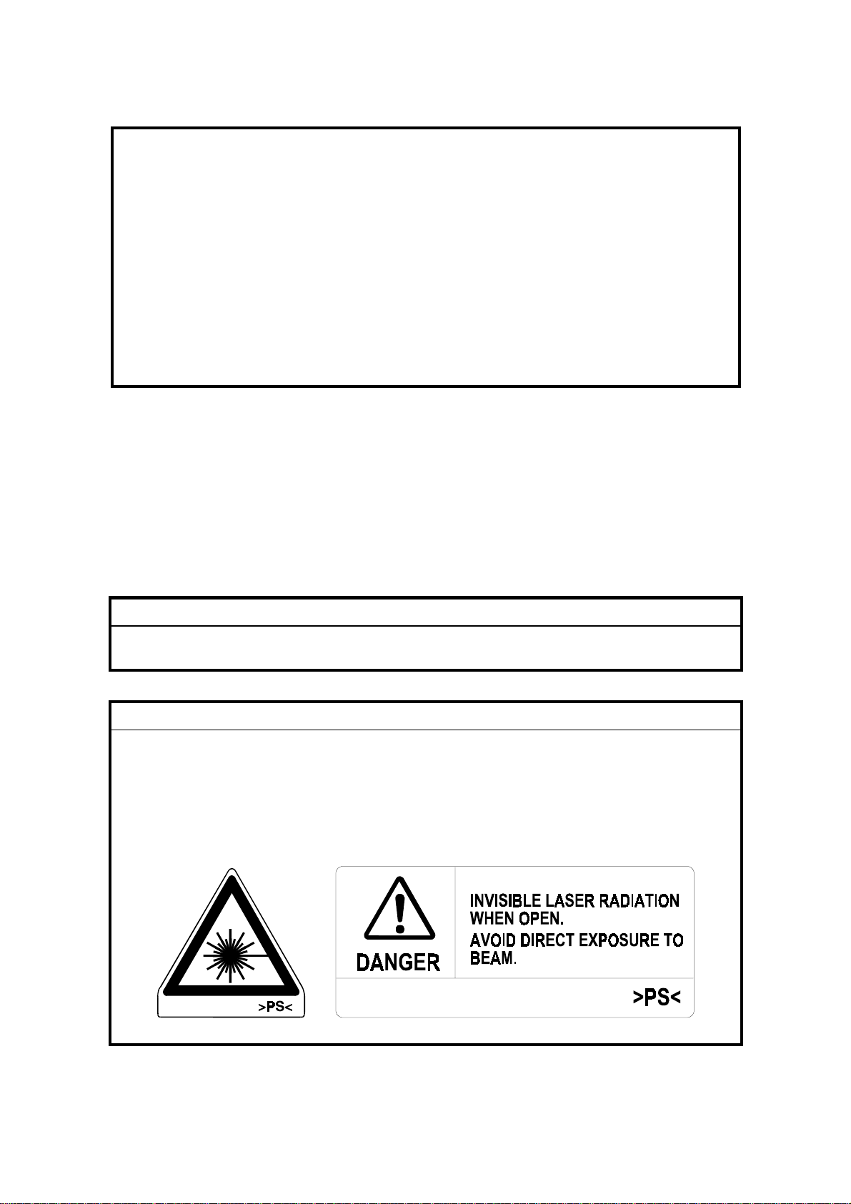
LASER SAFETY
The Center for Devices and Radiological Health (CDRH) prohibits the repair of
laser-based optical units in the field. The optical housing unit can only be repaired
in a factory or at a location with the requisite equipment. The laser subsystem is
replaceable in the field by a qualified Customer Engineer. The laser chassis is not
repairable in the field. Customer engineers are therefore directed to return all
chassis and laser subsystems to the factory or service depot when replacement of
the optical subsystem is required.
WARNING
I
Use of controls, or adjustment, or performance of procedures other than
those specified in this manual may result in hazardous radiation exposure.
WARNING
I
WARNING: Turn off the main switch before attempting any of the
procedures in the Laser Unit section. Laser beams can
seriously damage your eyes.
CAUTION MARKING:
Page 4

TABLE OF CONTENTS
1. OVERALL MACHINE INFORMAT ION........................................1-1
1.1 SPECIFICATIONS.................................................................................... 1-1
1.2 PAPER EXIT TRAY SELECTION............................................................. 1-4
1.3 MACHINE CONFIGURATION.................................................................. 1-5
1.3.1 SYSTEM COMPONENTS ............................................................... 1-5
1.3.2 INSTALLABLE OPTION TABLE...................................................... 1-7
1.4 MECHANICAL COMPONENT LAYOUT................................................... 1-8
1.5 PAPER PATH........................................................................................... 1-9
1.6 DRIVE LAYOUT ....................................................................................... 1-9
1.7 ELECTRICAL COMPONENT DESCRIPTIONS...................................... 1-10
1.8 BOARD STRUCTURE............................................................................ 1-14
1.8.1 BLOCK DIAGRAM......................................................................... 1-14
1.8.2 DESCRIPTIONS............................................................................ 1-15
2. DETAILED DESCRIPTIONS .......................................................2-1
2.1 SCANNING............................................................................................... 2-1
2.1.1 OVERVIEW ..................................................................................... 2-1
2.2 IMAGE PROCESSING .............................................................................2-2
2.2.1 OVERVIEW ..................................................................................... 2-2
2.2.2 SBU ................................................................................................. 2 -3
2.2.3 IMAGE PROCESSING .................................................................... 2-4
3. INSTALLATION PROCEDURE...................................................3-1
3.1 INSTALLATION REQUIREMENTS .......................................................... 3-1
3.1.1 ENVIRONMENT ..............................................................................3-1
3.1.2 MACHINE LEVEL............................................................................ 3-1
3.1.3 MINIMUM SPACE REQUIREMENTS.............................................. 3-2
3.1.4 POWER REQUIREMENTS.............................................................. 3-3
3.2 INSTALLATION FLOW CHART................................................................ 3-4
3.3 COPIER INSTALLATION.......................................................................... 3-5
3.3.1 ACCESSORY CHECK..................................................................... 3-5
3.3.2 INSTALLATION PROCEDURE........................................................ 3-6
3.4 PAPER TRAY UNIT INSTALLATION..................................................... 3-11
3.4.1 ACCESSORY CHECK................................................................... 3-11
3.4.2 INSTALLATION PROCEDURE...................................................... 3-12
3.5 1-BIN TRAY UNIT INSTALLATION ........................................................ 3-16
3.5.1 ACCESSORY CHECK................................................................... 3-16
3.5.2 INSTALLATION PROCEDURE...................................................... 3-17
3.6 BRIDGE UNIT INSTALLATION.............................................................. 3-22
3.6.1 ACCESSORY CHECK................................................................... 3-22
3.6.2 INSTALLATION PROCEDURE...................................................... 3-23
3.7 AUTO REVERSE DOCUMENT FEEDER INSTALLATION.................... 3-25
3.7.1 ACCESSORY CHECK................................................................... 3-25
3.7.2 INSTALLATION PROCEDURE...................................................... 3-26
i
Page 5

3.8 LCT INSTALLATION .............................................................................. 3-28
3.8.1 ACCESSORY CHECK................................................................... 3-28
3.8.2 INSTALLATION PROCEDURE...................................................... 3-29
3.9 1,000-SHEET FINISHER INSTALLATION.............................................. 3-31
3.9.1 ACCESSORY CHECK................................................................... 3-31
3.9.2 INSTALLATION PROCEDURE...................................................... 3-32
3.10 3,000-SHEET FINISHER INSTALLATION............................................ 3-35
3.10.1 ACCESSORY CHECK................................................................. 3-35
3.10.2 INSTALLATION PROCEDURE.................................................... 3-36
3.11 PUNCH UNIT INSTALLATION............................................................. 3-39
3.11.1 ACCESSORY CHECK................................................................. 3-39
3.11.2 INSTALLATION PROCEDURE.................................................... 3-40
3.12 PLATEN COVER INSTALLATION........................................................ 3-43
3.13 KEY COUNTER INSTALLATION .........................................................3-44
3.14 ANTI-CONDENSATION HEATER........................................................ 3-46
3.15 TRAY HEATER..................................................................................... 3-48
3.16 TRAY HEATER (OPTIONAL PAPER TRAY UNIT).............................. 3-49
4. SERVICE TABLES......................................................................4-1
4.1 SERVICE PROGRAM MODE TABLES.................................................... 4-1
4.1.1 TEST PATTERN PRINTING (SP2-902)......................................... 4-42
4.1.2 INPUT CHECK............................................................................... 4-43
4.1.3 OUTPUT CHECK........................................................................... 4-47
4.1.4 SYSTEM PARAMETER AND DATA LISTS (SMC LISTS)............. 4-48
4.1.5 NIP BAND WIDTH ADJUSTMENT (SP1-109)............................... 4-49
4.1.6 MEMORY ALL CLEAR (SP5-801)................................................. 4-50
4.1.7 SOFTWARE RESET...................................................................... 4-51
4.1.8 SYSTEM SETTING AND COPY SETTING (UP MODE) RESET... 4-51
4.1.9 NVRAM DATA DOWNLOAD......................................................... 4-52
4.2 PROGRAM DOWNLOAD....................................................................... 4-54
4.3 USER PROGRAM MODE....................................................................... 4-58
4.3.1 HOW TO ENTER AND EXIT UP MODE........................................ 4-58
4.3.2 UP MODE TABLE.......................................................................... 4-58
4.4 TEST POINTS/DIP SWITCHES/LEDS................................................... 4-60
4.4.1 DIP SWITCHES............................................................................. 4-60
4.4.2 TEST POINTS............................................................................... 4-60
4.4.3 LEDS ............................................................................................. 4-61
4.5 SPECIAL TOOLS AND LUBRICANTS ................................................... 4-61
4.5.1 SPECIAL TOOLS........................................................................... 4-61
4.5.2 LUBRICANTS................................................................................ 4-61
5. PREVENTIVE MAINTENANCE SCHEDULE...............................5-1
5.1 PM TABLE................................................................................................ 5-1
ii
Page 6

6. REPLACEMENT AND ADJUSTMENT ........................................ 6-1
6.1 SCANNER UNIT....................................................................................... 6-1
6.1.1 EXPOSURE GLASS........................................................................ 6-1
6.1.2 SCANNER EXTERIOR/OPERATION PANEL................................. 6-2
6.1.3 LENS BLOCK/SBU ASSEMBLY...................................................... 6-3
6.1.4 SCANNER MOTOR......................................................................... 6-4
6.1.5 SIB/LAMP STABILIZER................................................................... 6-5
6.2 LASER UNIT............................................................................................. 6-6
6.2.1 CAUTION DECAL LOCATIONS...................................................... 6-6
6.2.2 LASER UNIT.................................................................................... 6-7
6.2.3 LASER BEAM PITCH ADJUSTMENT............................................. 6-8
6.3 COPY ADJUSTMENTS: PRINTING/SCANNING..................................... 6-9
6.3.1 PRINTING........................................................................................ 6-9
6.3.2 SCANNING.................................................................................... 6-12
6.3.3 ADF IMAGE ADJUSTMENT.......................................................... 6-14
7. TROUBLESHOOTING.................................................................7-1
7.1 SERVICE CALL CONDITIONS................................................................. 7-1
7.1.1 SUMMARY....................................................................................... 7-1
7.1.2 SC CODE DESCRIPTIONS............................................................. 7-2
7.2 ELECTRICAL COMPONENT DEFECTS................................................ 7-24
7.2.1 SENSORS..................................................................................... 7-24
7.2.2 SWITCHES.................................................................................... 7-25
7.3 BLOWN FUSE CONDITIONS................................................................. 7-26
iii
Page 7
14 January, 2000 SPECIFICATIONS
1. OVERALL MACHINE INFORMATION
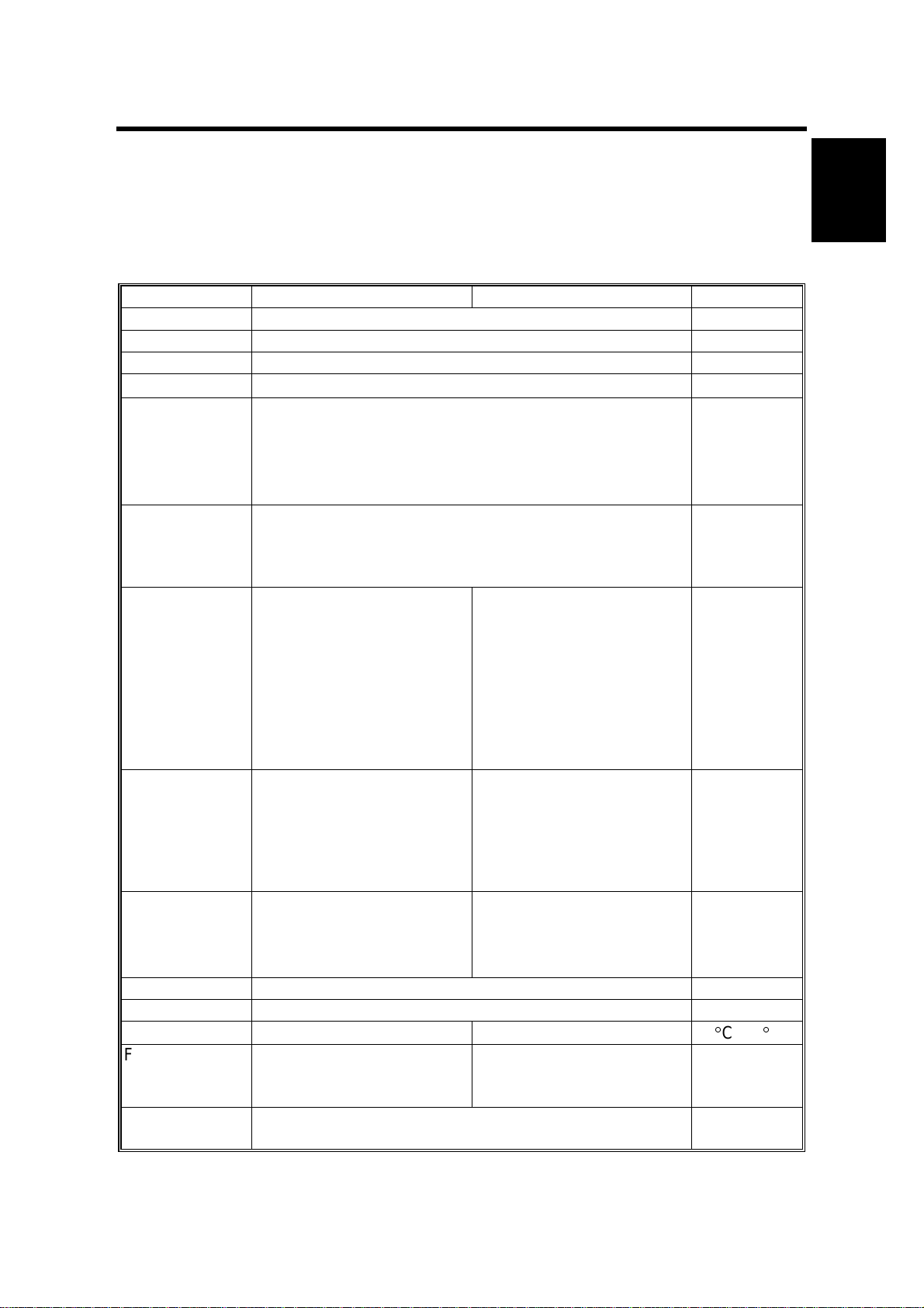
1.1 SPECIFICATIONS
The “*” mark indicates differences between these machines and the NAD
machines.
Adonis-C1b (35 cpm) Adonis-C1c (45 cpm) Note
Configuration: Desktop
Copy Process: Dry electrostatic transfer system
Original: Sheet/Book
Original Size
Copy Paper
Size:
Copy Paper
Weight:
Reproduction
Ratios:
Zoom: Both versions:
Copying Speed 35 cpm
Resolution*: Scanning and Printing: 600 dpi
Gradation: Scanning and Printing: 256 levels
Warm-up Time: Less than 85 s Less than 100 s
First Copy Time
(1st Tray):
Copy Number
Input:
Maximum A3/11
Maximum:
A3/11
Minimum:
A5/5.5
A6/5.5" x 8.5" lengthwise (By-pass)
Paper Tray/Duplex:
64 - 105 g/m
By-pass:
52 - 157 g/m
7R5E
Metric version (%):
400, 200, 141, 122, 115,
100, 93, 87, 82, 71, 65,
50, 25
Inch version (%):
400, 200, 155, 129, 121,
100, 93, 85, 78, 73, 65,
50, 25
25% to 400% in 1%
steps
(A4/11
19 cpm
(A3/11
Less than 3.9 s Less than 3.2 s
Ten-key pad, 1 to 999 Count up or
x 17
"
x 8.5" lengthwise (Paper tray / Duplex)
"
x 8.5" sideways)
"
x 17")
"
x 17
"
"
"
2
, 20 – 28 lb
2
, 16 – 42 lb
7R5E
Metric version (%):
400, 200, 141, 122, 115,
100, 93, 87, 82, 71, 65,
50, 35
Inch version (%):
400, 200, 155, 129, 121,
100, 93, 85, 78, 73, 65,
50, 32
Metric version:
35% to 400% in 1%
steps
Inch version:
32% to 400% in 1%
steps
45 cpm
(A4/11
22 cpm
(A3/11
x 8.5" sideways)
"
x 17")
"
Full size
Repeat copy
mode
23°C, 73°F
A4/11
sideways (1st
paper tray)
count down
x 8.5
"
Overall
Information
"
1-1
Page 8

SPECIFICATIONS 14 January, 2000
Adonis-C1b (35 cpm) Adonis-C1c (45 cpm) Note
Manual Image
Density
Selection:
Automatic
Reset:
Auto Shut Off:
Copy Paper
Capacity:
Copy Tray
Capacity:
Toner
Replenishment:
Toner Yield:
Power Source: North America
Dimensions
(W x D x H)
Weight: 75 kg (166 lb)
5 steps
60 s is the standard setting; it can be changed with a UP
mode.
60 min. is the standard setting; it can be changed with a
UP mode.
Paper Tray:
500 sheets (stack thickness up to 56 mm, 2.2
By-pass Feed:
50 sheets (stack thickness up to 5.5 mm, 0.2
A4/11
A3/B4/8.5
Cartridge exchange (700 g/cartridge)
27k copies
670 x 640 x 720 mm (26.4
x 8.5": 500 sheets
"
x 14"/11" x 17": 250 sheets
"
(A4 sideways, 6% full black, 1 to 1 copying, ADS
mode)
120V/60Hz, More than 12 A
x 25.2" x 28.3")
"
"
)
"
) x 2
Standard
copy tray
Without
options
Power Consumption:
Mainframe only
Adonis-C1b Adonis-C1c Note
Maximum Less than 1.44 kW Less than 1.44 kW
Copying Less than 1.05 kW Less than 1.05 kW
Warm-up Less than 1.00 kW Less than 1.05 kW
Stand-by Less than 200 Wh Less than 220 Wh
System
Adonis-C1b Adonis-C1c Note
Maximum Less than 1.44 kW Less than 1.44 kW
Copying Less than 1.15 kW Less than 1.15 kW
Warm-up Less than 1.00 kW Less than 1.05 kW
Stand-by Less than 200 Wh Less than 230 Wh
Without the optional
heaters, fax unit,
and printer
controller.
1-2
Page 9

14 January, 2000 SPECIFICATIONS
Noise Emission:
Mainframe Only Full System
Copying
Adonis-C1b
Adonis-C1c
Stand-by
Adonis-C1b
Adonis-C1c
52 dB(A) or less
56 dB(A) or less
27 dB(A) or less
27 dB(A) or less
60 dB(A) or less
62 dB(A) or less
28 dB(A) or less
28 dB(A) or less
Overall
Information
NOTE:
1) The above measurements were made in accordance with ISO 7779.
2) Full system measurements do not include the optional fax unit and the
printer controller.
3) In the above stand-by condition, the polygon motor is not rotating.
1-3
Page 10
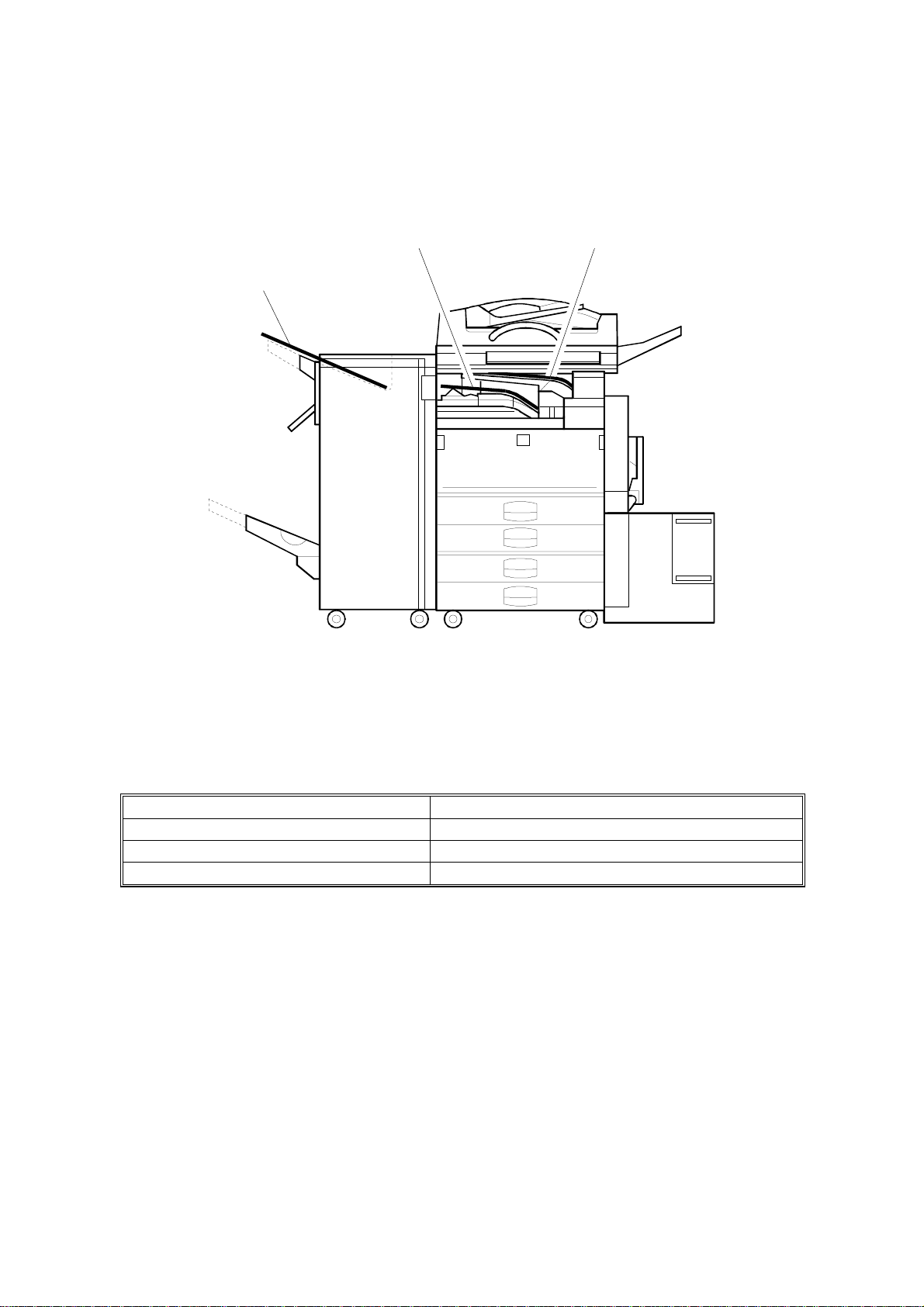
PAPER EXIT TRAY SELECTION 14 January, 2000
1.2 PAPER EXIT TRAY SELECTION
[A] A4, LT [B] A3, LT
[C] Longer than A3, DLT
A284V508.WMF
The machine allows selection between the paper tray exit trays: Int. Tray [A]
(standard output tray), Int. Tray 2 [B] (optional one-bin tray), and Ext. Tray [C]
(finisher or optional external output tray). If the sub-scan length is more than 330
mm, the exit tray is as shown below, if the relevant options have been installed.
Installed options Exit tray for paper longer than 330 mm
Bridge unit & Finisher (1,000-sheet) Int. Tray [A]
Bridge unit & Finisher (3,000-sheet) Ext. Tray [C]: The finisher upper tray
Bridge unit & optional ext. output tray Ext. Tray [C]: Ext. output tray
1-4
Page 11
14 January, 2000 MACHINE CONFIGURATION
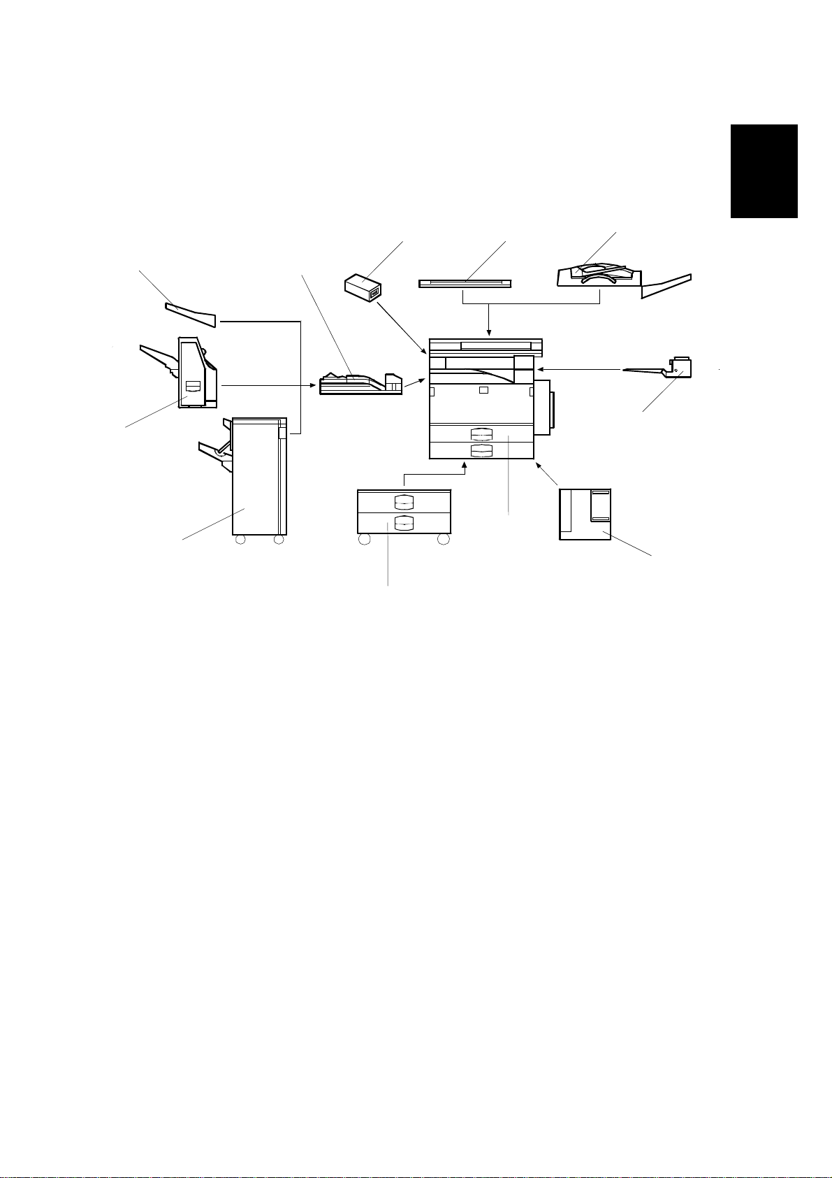
1.3 MACHINE CONFIGURATION
1.3.1 SYSTEM COMPONENTS
Overall
Information
11 1
9
10
2
3
8
5
7
4
6
A284V502.WMF
1-5
Page 12

MACHINE CONFIGURATION 14 January, 2000
Symbol: U: Unique option, C: Option also used with other products
Version Item Machine Code No. Note
Copier (Adonis-C1b) A283 5
Copier (Adonis-C1c) A284 5
ARDF (Option) A680 2 C: (NAD)
Platen Cover (Option) A381 1 C: (NAD)
Paper Tray Unit (Option) A682 6 C: (NAD)
LCT (Option) A683 4 C: (NAD)
1-bin Tray (Option) A684 3 C: (NAD)
Copy
Fax
Printer
Scanner
Bridge Unit (Option) A688 10 C: (NAD)
1000-sheet Finisher (Option) A681 8 C: (NAD)
3000-sheet Finisher
(Option – Adonis-C1c only)
Punch Unit
(Option for 3000-sheet Finisher)
External Output Tray (Option) A825 9 C: (NAD)
Key Counter Bracket (Option) A674 11 C: (NAD)
Expansion Box (Option) A872 --- U
Fax Unit (Option) A874 --- U
ISDN Unit (Option) A816 --- C: (NAD)
RAM SIMM (Option) --- --400-dpi High Resolution (Option) A892 --- C: (Russian)
PC-Fax Expander B368 --- U
Handset (Option) A646 --- C: (NAD)
Stamp Unit (Option) A813 --- C: (NAD)
Printer Controller B358 --- U
PostScript Kit A854 --- C: (NAD)
Hard Disk A853 --- C: (NAD)
Network Interface Board A855 --- C: (NAD)
Mailbox G909 --- C: (NAD)
Mailbox Bridge Unit G912 --- C: (NAD)
RAM SIMM --- --Scanner Kit B359 --- U
RAM SIMM --- ---
A812-17 (3 holes)
A812-27 (2 holes)
A697 7 C: (NAD)
--- C: (NAD)
Symbol: U: Unique options C: Option also used with other products
1-6
Page 13
14 January, 2000 MACHINE CONFIGURATION
1.3.2 INSTALLABLE OPTION TABLE
Copier options
Option Adonis-C1b Adonis-C1c Note
ARDF
Platen Cover
Paper Tray Unit
LCT
1-bin Tray
Bridge Unit
1,000-sheet Finisher
3,000-sheet Finisher
Punch Unit
External Output Tray
Key Counter Bracket
Expansion Box
Printer options
¢
= Available,
¢¢
¢¢
¢¢
D
D
¢¢
¢¢
D
D
X
X
D
D
¢¢
¢¢
D
= Requires another option, X = Not available
D
D
D
D
D
D
D
D
D
D
Requires the paper tray unit.
Requires the paper tray unit
and bridge unit.
Requires the paper tray unit
and bridge unit.
Requires the 3000-sheet
finisher.
Requires the bridge unit.
It is required only when the
fax option and/or printer
option is installed.
Overall
Information
Option Adonis-C1b Adonis-C1c Note
PostScript Kit
Hard Disk
Network Interface
Board
Mailbox
Mailbox Bridge Unit
RAM SIMM
¢
= Available,
¢¢
¢¢
¢¢
D
D
D
D
¢¢
D
D
D
D
D
= Requires another option
Requires the paper tray unit.
Requires the mailbox.
Fax options and scanner kits
All options for the fax unit are available when the fax unit has been installed.
Relationship between main machine, mailbox, and finisher
¢
= Available, X = Not available
Model Mailbox 1000- sheet Finisher 3000-sheet Finisher
Adonis-C1b
Adonis-C1c
Installed
Not Installed
Installed
Not Installed
XX
¢
X
¢¢
X
¢
1-7
Page 14
MECHANICAL COMPONENT LAYOUT 14 January, 2000
1.4 MECHANICAL COMPONENT LAYOUT
321 654 987
10
42
41
40
39
38
37
36
11
12
13
14
15
16
17
18
19
20
21
23
24
25
26
22
1-8
27
29 28
31 3033 3235 34
A284V503.WMF
Page 15

14 January, 2000 PAPER PATH
1. Exposure Glass
2. 2nd Mirror
3. Original Width Sensors
4. 1st Mirror
5. Exposure Lamp
6. Original Length Sensors
7. Lens
8. SBU
9. Scanner Motor
10. Hot Roller
11. Entrance Sensor
12. Inverter Gate
13. Inverter Roller
14. Pressure Roller
15. Transfer Belt Cleaning Blade
22. By-pass Tray
23. Pick-up Roller
24. Paper End Sensor
25. Paper Feed Roller
26. Separation Roller
27. Upper Relay Roller
28. Feed Roller
29. Separation Roller
30. Pick-up Roller
31. Bottom Plate
32. Development Unit
33. Charge Roller
34. Fq Mirror
35. Barrel Toroidal Lens (BTL)
36. Polygonal Mirror Motor
Overall
Information
16. Upper Transport Roller
17. Transfer Belt
18. OPC Drum
19. Registration Roller
20. Lower Transport Roller
21. Exit Sensor
37. Laser Unit
38. Toner Supply Bottle Holder
39. Exit Junction Gate
40. Exit Roller
41. Paper Exit Sensor
42. 3rd Mirror
1.5 PAPER PATH
The paper path is the same as for NAD machines.
1.6 DRIVE LAYOUT
The drive layout is the same as for NAD machines.
1-9
Page 16

ELECTRICAL COMPONENT DESCRIPTIONS 14 January, 2000
1.7 ELECTRICAL COMPONENT DESCRIPTIONS
Refer to the electrical component layout and the point-to-point diagram on the
waterproof paper in the pocket for the locations of these components.
Symbol
Printed Circuit Boards
PCB1 58
PCB2 55
PCB3 61
PCB4 62
PCB5 63
PCB6 9
PCB7 7
PCB8 11
PCB9 4 Lamp Stabilizer Provides dc power to the exposure lamp.
PCB10 19
PCB11 54
PCB12 65
Index
No.
Description Note
BICU (Base Engine &
Image Control Unit)
PSU
(Power Supply Unit)
IOB
(Input/Output Board)
Paper Feed Control
(PFB)
High Voltage Supply Supplies high voltage to the drum charge
SBU
(Sensor Board Unit)
SIB
(Scanner Interface
Board)
Operation Panel Controls the LCD and LED matrix and
LDDR
(Laser Diode Driver)
SIFB (Scanner
Interface Board)
Main (Duplex)
Controls all copier functions both directly and
through other control boards.
Provides dc power to the system and ac
power to the fusing lamp and optional
heaters.
Controls the mechanical parts of the printer
(excluding the paper feed section), and the
fusing lamp power.
Controls the mechanical parts of all paper
feed sections.
roller, development roller, and transfer belt.
Contains the CCD, and outputs a video
signal to the BICU board.
Controls the scanner carriages and passes
signals from the scanner unit to the BICU
board.
monitors the key matrix.
Controls the laser diode.
Passes signals between the SBU and BICU
boards.
Controls the duplex unit and communicates
with the copier.
Motors
M1 35 Main Drives the main body components.
M2 8 Scanner Drive Drives the 1st and 2nd scanners.
M3 45 Tray Lift Raises the bottom plate in the paper tray.
M4 22 Polygonal Mirror Turns the polygonal mirror.
M5 20
M6 36 Cooling Fan Removes heat from the main PCBs.
M7 37 Exhaust Fan Removes heat from around the fusing unit.
M8 34
M9 56 PSU Cooling Fan Removes heat from the PSU.
M10 64 Inverter (Duplex) Drives the duplex inverter roller.
M11 66
LD Positioning
Toner Supply Rotates the toner bottle to supply toner to the
Transport (Duplex) Drives the duplex upper and lower transport
Rotates the LD unit to adjust the LD beam
pitch when a different resolution is selected.
development unit.
rollers.
1-10
Page 17

14 January, 2000 ELECTRICAL COMPONENT DESCRIPTIONS
Symbol
Index
No.
Description Note
Sensors
S1 2
Scanner Home
Position
Informs the CPU when the 1st and 2nd
scanners are at the home position.
Platen Cover Informs the CPU whether the platen cover is
S2 3
up or down (related to APS/ARE functions).
ARE: Auto Reduce and Enlarge
S3 12
S4 5
S5 6
S6 21
S7 17
Original Width Detects the width of the original. This is one
of the APS (Auto Paper Select) sensors.
Original Length-1 Detects the length of the original. This is one
of the APS (Auto Paper Select) sensors.
Original Length-2 Detects the length of the original. This is one
of the APS (Auto Paper Select) sensors.
LD Unit Home
Position
Informs the CPU when the LD unit is at the
home positon.
Toner Density (TD) Detects the amount of toner inside the
development unit.
S8 24 Paper Exit Detects misfeeds.
Registration Detects the leading edge of the copy paper
S9 27
to determine the stop timing of the paper
feed clutch, and detects misfeeds.
Image Density (ID) Detect s the density of various patterns and
S10 26
the reflectivity of the drum for process
control.
S11 28
S12 30
S13 29
S14 31
Upper Paper Height Detects when the paper in the upper paper
tray is at the feed height.
Lower Paper Height Detects when the paper in the lower paper
tray is at the feed height.
Upper Paper End Informs the CPU when the upper paper tray
runs out of paper.
Lower Paper End Informs the CPU when the lower paper tray
runs out of paper.
S15 33 Upper Relay Detects misfeeds.
S16 32 Lower Relay Detects misfeeds.
S17 48
S18 46
S19 38
S20 18
S21 61
Upper Tray Informs the CPU whether the upper paper
tray is set into the machine or not.
Lower Tray Informs the CPU whether the lower paper
tray is set into the machine or not.
Transfer Belt Position Informs the CPU of the current position of the
transfer belt unit.
Toner Overflow Detects toner overflow in the toner collection
tank.
Duplex Entrance
Detects the trailing edge of the copy paper to
turn on the inverter gate solenoid and turn on
the inverter motor in reverse. Checks for
misfeeds.
S22 67 Exit (Duplex) Checks for misfeeds.
S23 68
Cover Guide (Duplex) Det ects whether the cover guide is opened
or not.
Overall
Information
1-11
Page 18

ELECTRICAL COMPONENT DESCRIPTIONS 14 January, 2000
Symbol
S24 69
S25 72
Switches
SW1 43
SW2 49
SW3 51
SW4 52
SW5 10
SW6 62
Index
No.
Description Note
Paper End
(By-pass)
Paper Size Sensor
Board
Informs the copier when the by-pass tray
runs out of paper.
Detects the paper width for the by-pass tray
unit.
(By-pass)
Right Lower Cover Detects whether the right lower cover is open
or closed.
Right Upper Cover Cut the +5VLD and +24V dc power line and
detects whether the right upper cover is open
or closed.
Main Power Switch Supplies power to the copier. If this is off,
there is no power supplied to the copier.
Front Cover Safety Cuts the +5VLD and +24V dc power line and
detects whether the front cover is open or
not.
Operation Switch Provides power for machine operation. The
machine still has power if this switch is off.
Duplex Unit
Detects whether the duplex unit is opened or
not.
Magnetic Clutches
CL1 3 9
Transfer Belt Controls the touch and release movement of
the transfer belt unit.
CL2 40 Registration Drives the registration rollers.
CL3 4 4 Relay Drives the relay rollers.
CL4 41 Upper Paper Feed Starts paper feed from the upper paper tray.
CL5 42 Lower Paper Feed Starts paper feed from the lower paper tray.
CL6 7 1
Paper Feed
(By-pass)
Starts paper feed from the by-pass tray unit.
Solenoids
SOL1 63
SOL2 70
SOL3 73
SOL4 74
Inverter Gate
(Duplex)
Pick-up
(By-pass)
Exit Junction Gate
(Interchange unit)
Duplex Junction Gate
(Interchange unit)
Controls the duplex inverter gate.
Moves the pick-up roller for the by-pass feed
tray to contact the paper.
Controls the exit junction gate.
Controls the duplex junction gate.
Lamps
L1 13
Exposure
Applies high intensity light to the original for
exposure.
L2 16 Fusing Provides heat to the hot roller.
L3 25
Quenching Neutralizes any charge remaining on the
drum surface after cleaning.
1-12
Page 19

14 January, 2000 ELECTRICAL COMPONENT DESCRIPTIONS
Symbol
Index
Heaters
H1 1
H2 47
Thermistors
TH1 14
Thermofuses
TF1 15
Counters
CO1 50
CO2 N/A
No.
Description Note
Optics Anticondensation
(option)
Tray
(option)
Turns on when the main power switch is off
to prevent moisture from forming on the
optics.
Turns on when the main power switch is off
to keep paper dry in the paper tray.
Fusing Monitors the temperature at the central area
of the hot roller.
Fusing Provides back up overheat protection in the
fusing unit.
Total Keeps track of the total number of prints
made.
Key
(option)
Used for control of authorized use. If this
feature is enabled for copying, copying will
be impossible until it is installed. It can also
be enabled for fax and printer modes
separately.
Overall
Information
Others
LSD 23
Laser
Synchronization
Detector
Detects the laser beam at the start of the
main scan.
1-13
Page 20
BOARD STRUCTURE 14 January, 2000
1.8 BOARD STRUCTURE
1.8.1 BLOCK DIAGRAM
SBU
Exposure
Lamp
Image data
Signal data
Lamp
Stabilizer
Scanner
Motor
APS
Sensors
Op.
Panel
ARDF
SIFB
SIB
BICU
Driver
Polygon
Motor
Mother
Board
LD
PSU
HDD
LSD
Fax Controller
Printer Controller
Scanner Controller
Duplex
Unit
1-bin Tray
Finisher
Main
Bridge Unit
IOB
Counter Clutches
: Standard : Option
Fans Sensors
Motor
High
Voltage
Supply
Paper Feed
Controller
(PFB)
Paper
Tray Unit
LD
Position
Motor
LCT
A284V501.WMF
LD H.P
Sensor
Sensors
Clutches
1-14
Page 21

14 January, 2000 BOARD STRUCTURE
1.8.2 DESCRIPTIONS
1. BICU (Base Engine and Image Control Unit)
This is the main board. It controls the following functions.
·
Engine sequence
·
Timing control for peripherals
·
Image processing, video control
·
Operation control
·
Application boards (fax, printer, scanner)
2. IOB (Input/Output Board)
The IOB handles the following functions.
·
Drive control for the sensors, motors, and solenoids in the printer engine
·
PWM control for the high voltage supply board
·
Serial interface with peripherals
·
Fusing control
Overall
Information
3. SBU (Sensor Board Unit)
The SBU receives analog signals from the CCD and converts them into digital
signals.
4. SIB (Scanner Interface Board)
This board controls the scanner motor and passes signals between the BICU
board and the component parts of the scanner unit.
5. SIFB (Scanner Interface Board)
This board interfaces the SBU with the BICU.
6. Mother Board (Option)
This board interfaces the BICU with the fax controller, printer controller and/or
the scanner kit. The mother board is part o f the ex pansi on box option.
1-15
Page 22
14 January, 2000 SCANNING
2. DETAILED DESCRIPTIONS
2.1 SCANNING
2.1.1 OVERVIEW
For NAD
A284D501.WMF A284D502.WMF
For Adonis-C1
The mechanical components of the scanner unit are the same as for the NAD.
However, the following items have been changed because this machine scans at
600 dpi.
·
The lens is larger
·
Because the lens size has been changed, the drive layout has been changed as
shown in the above illustration (note the position of the scanner drive motor).
·
Image processing is slightly different
·
To reduce the electrical noise generated by the high frequency image data
signal, a shield plate has been added to the lens block unit.
Detailed
Descriptions
2-1
Page 23
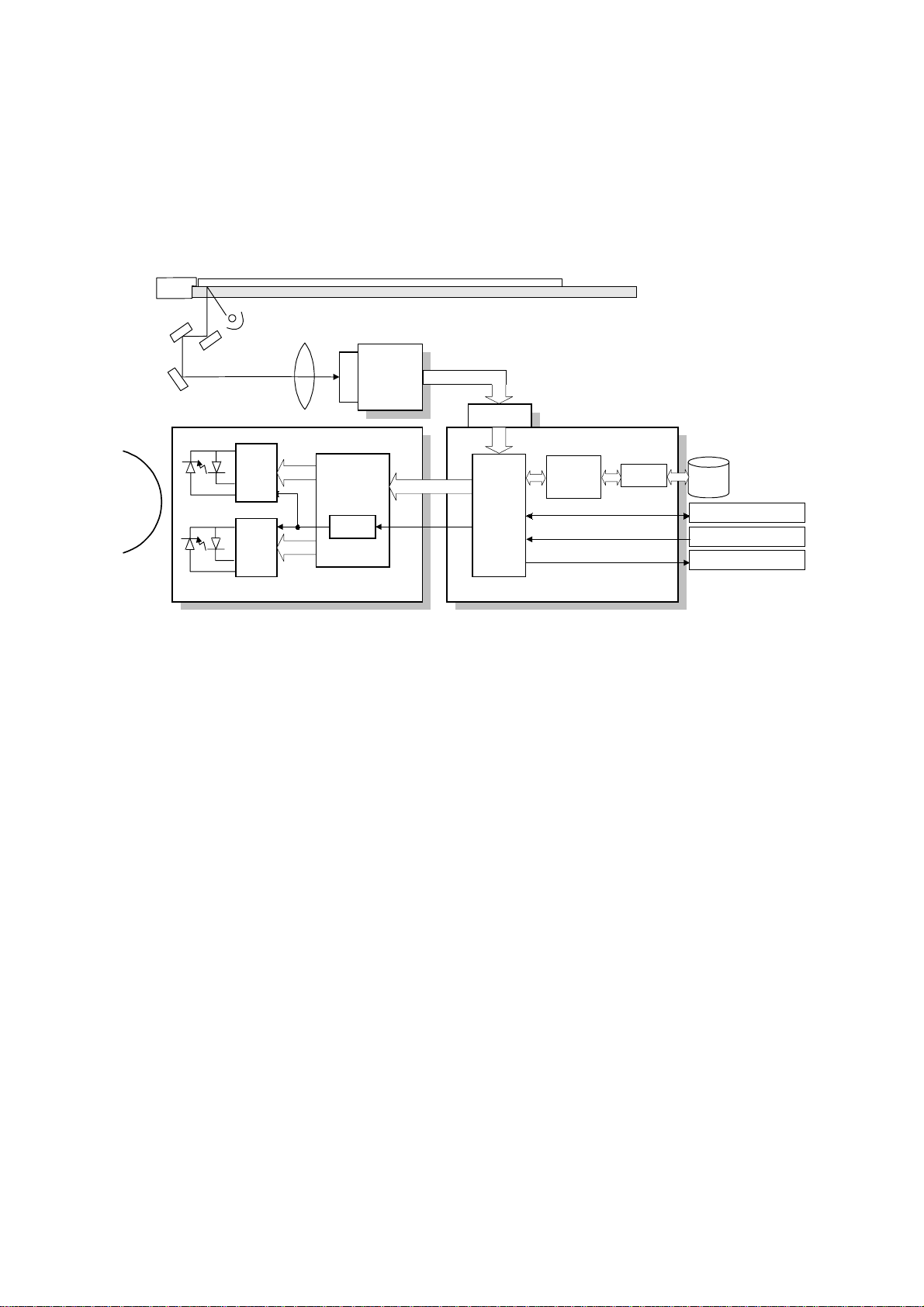
IMAGE PROCESSING 14 January, 2000
2.2 IMAGE PROCESSING
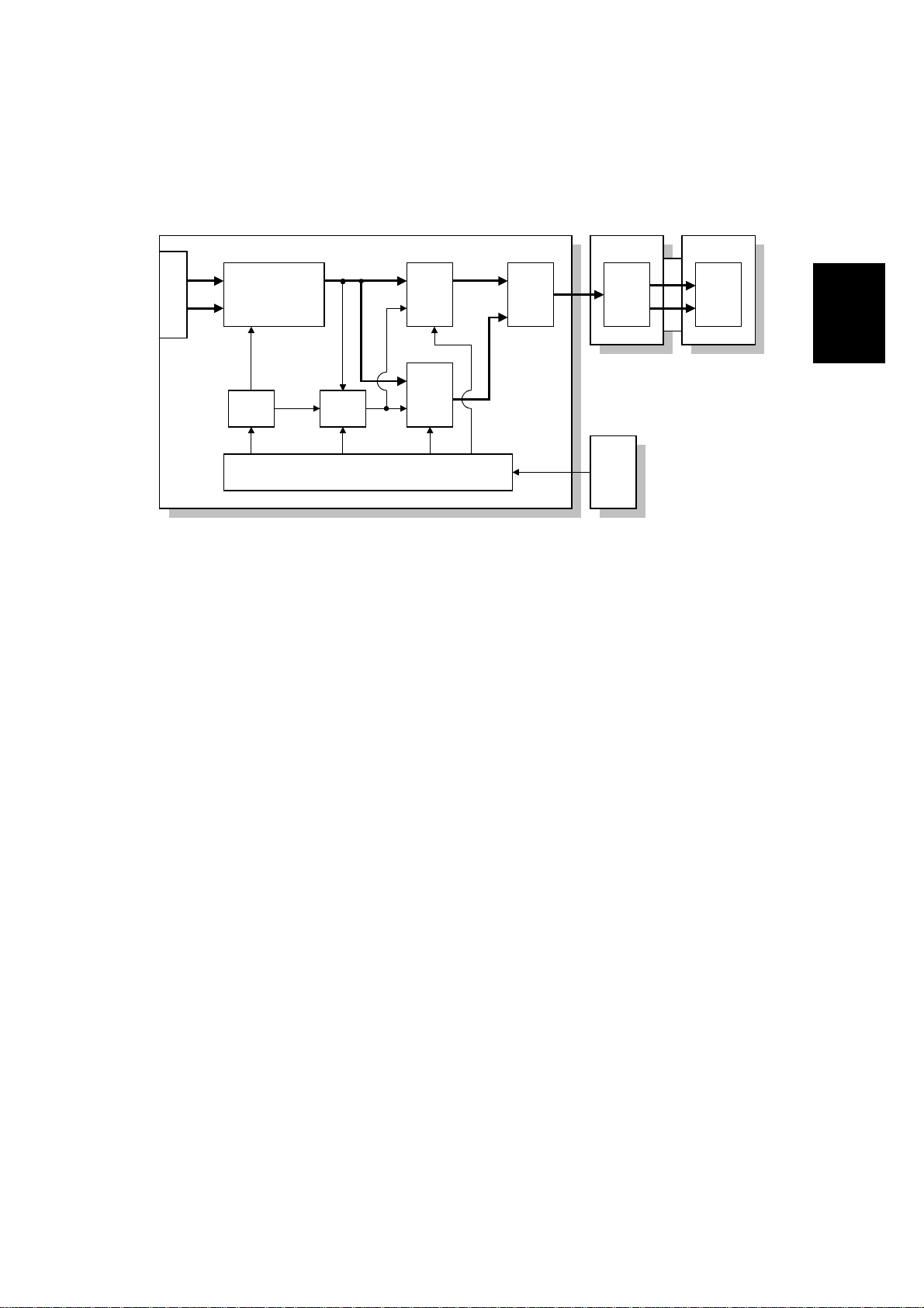
2.2.1 OVERVIEW
SBU
CCD
SIFB
Memory
Control
IC
MSU
BICU
HDD
Fax Controller
Printer Controller
Scanner Controller
A284D531.WMF
Drum
LDDR
LD
Driver
LD
Driver
LD
Controller
(GAVD)
FCI
IPU
The image data flows similarly to the NAD machine. The differences are the
following.
·
The video data go to the IPU chip through only the SIFB.
·
The MSU circuit is on the BICU board.
·
The image processing is changed.
2-2
Page 24
14 January, 2000 IMAGE PROCESSING
g
2.2.2 SBU
E
O
CCD
Analo
Processing IC
D/A
P/H
SBU
GA
A/D
A/D
Driver
SIFB
Driver
SIB
BICU
IPU
A283D500.WMF
The CCD has two output lines, one each for odd and even pixels, to the analog
processing IC. The analog processing IC performs the zero clamp and signal
amplification. The analog signals are then converted to 8-bit signals by the A/D
converter. The digital signals go to the driver, where they are converted to serial
data. Then, these go to the SIFB. In the SIFB, the data is converted to parallel
signals (8-bit x 2) by the driver, and these go to the IPU chip.
Detailed
Descriptions
The SIB controls the circuits on the SBU (such as those for shading).
2-3
Page 25
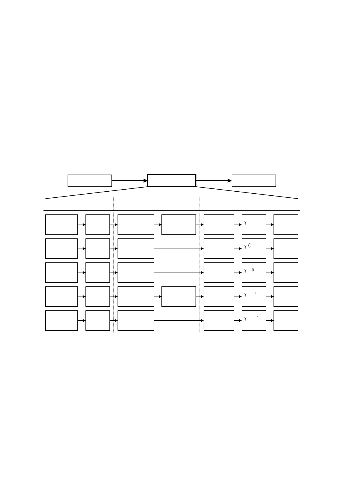
IMAGE PROCESSING 14 January, 2000
2.2.3 IMAGE PROCESSING
Overview
The differences in the image processing from the NAD are as follows.
·
600 dpi scanning and printing
·
Only grayscale processing mode is available.
·
The copy quality for the low contrast image is improved (the filters and the g table
have been modified).
·
To consist with gradation and resolution in the text mode, using the error
diffusion processing.
Image Processing Path
Scanning Image Processing Printing
Copy Mode
Letter Magnification
Letter/Photo Magnification
Generation Magnification
Low Density
Original
Input
Correction
Auto
Shading
Auto
Shading
Auto
Shading
Auto
Shading
Auto
Shading
Magnification
Magnification
Background
Erase
Background/
Independent
Dot Erase
Background/
Independent
Dot Erase
Filtering
MTF
(Strong)
MTF
(Weak)
Smoothing
MTF/
Line width
correction
MTF
(Strong)
Photo mode: MTF can be used instead of smoothing (SP4-904-3).
ID
Control
Corre-
g
ction
Corre-
g
ction
Corre-
g
ction
Corre-
g
ction
Corre-
g
ction
Gradation
Error
Diffusion
Error
Diffusion
DitheringPhoto Magnification
Error
Diffusion
Error
Diffusion
A284D533.WMF
2-4
Page 26

14 January, 2000 IMAGE PROCESSING
SP modes for each image processing mode
Copy
mode
Letter
Letter/
Photo
Photo
Copied
Original
Low
Density
Original
Background
erase
SP4903-34
Background erase
level
SP4903-28
Independent dot
erase level
SP4903-35
Background erase
level
SP4903-30
Independent dot
erase level
SP4903-36
Background erase
level
SP4903-37
Background erase
level
SP4903-32
Independent dot
erase level
SP4903-31
Independent dot
erase level
Filtering Magnification Gradation
SP4903-11~14,
41~44
SP2909-1
Main scan mag.
MTF filter
coefficient
SP4903-20~23,
50~53
MTF filter strength
SP4903-17, 47
MTF filter
SP2909-1
Main scan mag.
coefficient
SP4903-25, 55
MTF filter strength
SP4904-3
Filter type
SP2909-1
Main scan mag.
SP4904-2
Dither matrix type
(smoothing or
MTF)
SP4903-16
Smoothing filter
coefficient
SP4903-15, 48
MTF filter
coefficient
SP4903-24, 54
MTF filter strength
SP4903-19, 46
MTF filter
coefficient
SP2909-1
Main scan mag.
SP4904-6
Line width
correction type
SP4903-27, 57
MTF filter strength
SP4903-18, 45
MTF filter
SP2909-1
Main scan mag.
coefficient
SP4903-26, 56
MTF filter strength
Detailed
Descriptions
2-5
Page 27
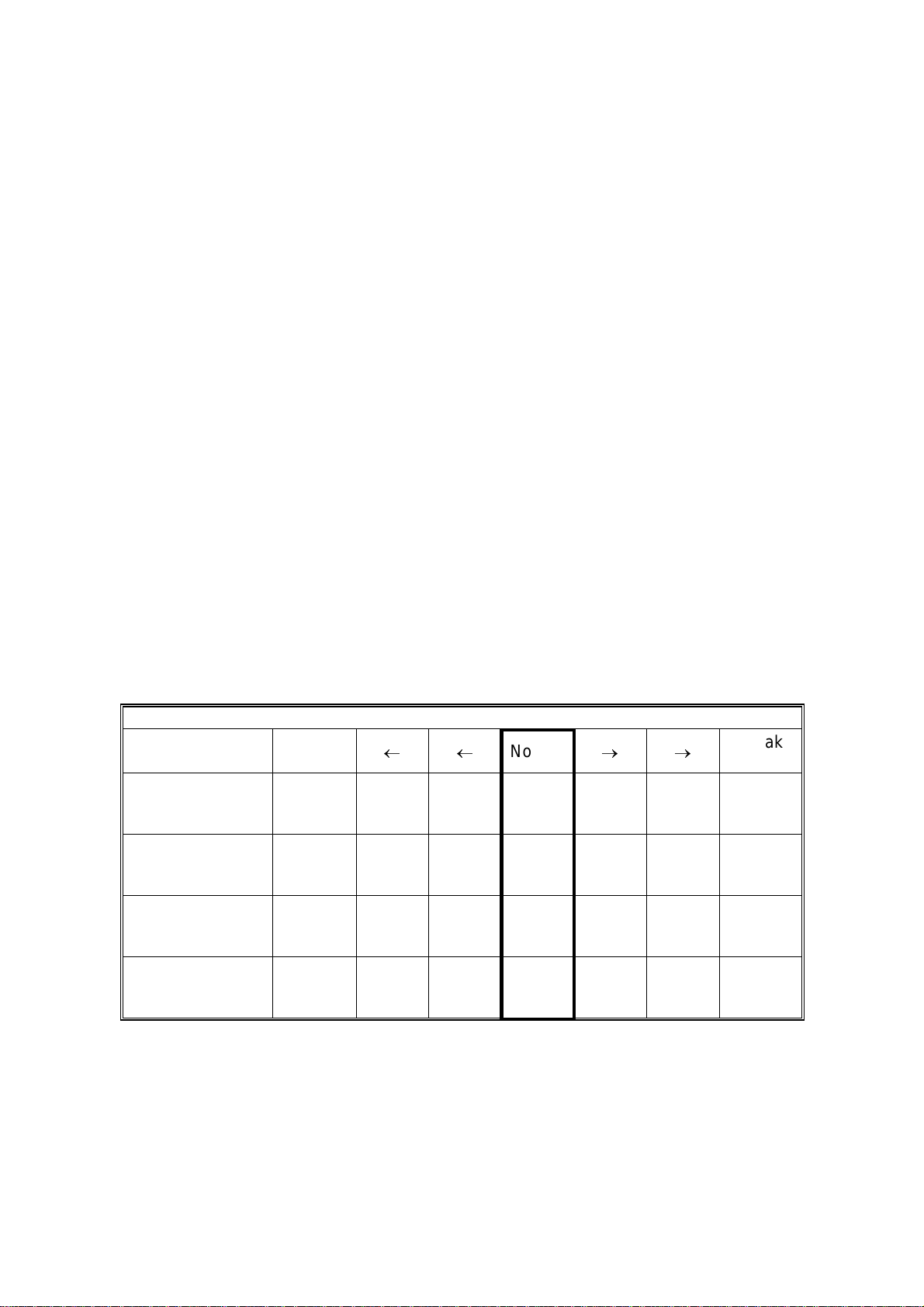
IMAGE PROCESSING 14 January, 2000
Filtering
There are two software filters: MTF and smoothing, as in the NAD. There are four
MTF filter types: filter strength for main scan direction, filter strength for sub scan
direction, filter coefficient for main scan direction, and filter coefficient for sub scan
direction. These filters can be adjusted with SP mode.
When the filter is stronger in the main scan direction, lines parallel to the feed
direction are emphasized. When the filter is stronger in the sub scan direction, lines
at right angles to the feed direction are emphasized.
The relationship between the filter coefficient and the filter strength is as follows.
MTF filter coefficient
(Weak) (Strong)
0 ® 1 ® 2 ® 3 ® 4 ® 5 ® 6 ® 7 ® 8 ® 9 ® 10 ® 11 ® 12 ® 13 ® 14 ® 15
MTF filter strength
(Weak) 0 ® 1 ® 2 ® 3 ® 4 ® 5 ® 6 ® 7 (Strong)
Smoothing filter coefficient
(Weak) 0 ® 1 ® 2 ® 3 ® 4 ® 5 ® 6 ® 7 (Strong)
It is difficult to explain how to use the filter coefficient and filter strengths to control
MTF and smoothing. Refer to the following charts to determine how to make the
filters weaker or stronger. The values in the bold columns are the default settings.
Text mode: 25 ~ 64 %
MTF strength Strong
(Sharp)
Main scan:
Filter coefficient
(SP4903-11)
Sub scan:
Filter coefficient
(SP4903-41)
Main scan:
Filter Strength
(SP4903-20)
Sub scan:
Filter Strength
(SP4903-50)
9 15141210 9 9
11 13 13 12 12 12 10
3 22222 2
3 22222 2
¬¬
Normal
®®
Weak
(Soft)
2-6
Page 28
14 January, 2000 IMAGE PROCESSING
Text mode: 65 ~ 154 %
MTF strength
Strong
(Sharp)
¬¬
Normal
®®
Weak
(Soft)
Main scan:
Filter coefficient
9 9 15 14 12 10 9
(SP4903-12)
Sub scan:
Filter coefficient
13 11 13 13 13 13 13
(SP4903-42)
Main scan:
Filter Strength
3 32222 2
(SP4903-21)
Sub scan:
Filter Strength
3 32222 2
(SP4903-51)
Text mode: 155 ~ 400 %
MTF strength
Strong
(Sharp)
¬¬
Normal
®®
Weak
(Soft)
Main scan:
Filter coefficient
10 9 9 15 14 12 10
(SP4903-13)
Sub scan:
Filter coefficient
13 13 11 13 13 13 13
(SP4903-43)
Main scan:
Filter Strength
3 33222 2
(SP4903-22)
Sub scan:
Filter Strength
3 33222 2
(SP4903-52)
Detailed
Descriptions
Text mode: Notch 1 (lightest image density setting), 65 ~ 154 %
MTF strength
Strong
(Sharp)
¬¬
Normal
Main scan:
Filter coefficient
9 9 15 14 12 10 9
(SP4903-14)
Sub scan:
Filter coefficient
13 11 13 13 13 13 13
(SP4903-44)
Main scan:
Filter Strength
4 43333 3
(SP4903-23)
Sub scan:
Filter Strength
4 43333 3
(SP4903-53)
2-7
®®
Weak
(Soft)
Page 29
IMAGE PROCESSING 14 January, 2000
Photo mode: (when MTF filtering is selected with SP4903-3)
MTF strength
Strong
(Sharp)
¬¬
Normal
®®
Weak
(Soft)
Main scan:
Filter coefficient
9 9 15 14 12 10 9
(SP4903-15)
Sub scan:
Filter coefficient
13 11 13 13 13 13 13
(SP4903-48)
Main scan:
Filter Strength
2 21111 1
(SP4903-24)
Sub scan:
Filter Strength
2 21111 1
(SP4903-54)
Text/Photo mo de
MTF strength
Strong
(Sharp)
¬¬
Normal
®®
Weak
(Soft)
Main scan:
Filter coefficient
9141098109
(SP4903-17)
Sub scan:
Filter coefficient
10 13 13 10 9 13 10
(SP4903-47)
Main scan:
Filter Strength
2 11110 0
(SP4903-25)
Sub scan:
Filter Strength
2 11110 0
(SP4903-55)
2-8
Page 30
14 January, 2000 IMAGE PROCESSING
Low density mode
MTF strength
Strong
(Sharp)
¬¬
Normal
®®
Weak
(Soft)
Main scan:
Filter coefficient
14 12 10 9 9 14 10
(SP4903-18)
Sub scan:
Filter coefficient
13 13 13 13 10 13 13
(SP4903-45)
Main scan:
Filter Strength
3 33332 2
(SP4903-26)
Sub scan:
Filter Strength
3 33332 2
(SP4903-56)
Copied original mode
MTF strength
Strong
(Sharp)
¬¬
Normal
®®
Weak
(Soft)
Main scan:
Filter coefficient
9 9 12 10 9 9 14
(SP4903-19)
Sub scan:
Filter coefficient
13 10 13 13 13 10 13
(SP4903-46)
Main scan:
Filter Strength
3 32222 1
(SP4903-27)
Sub scan:
Filter Strength
3 32222 1
(SP4903-57)
Detailed
Descriptions
2-9
Page 31

14 January, 2000 INSTALLATION REQUIREMENTS
3. INSTALLATION PROCEDURE
3.1 INSTALLATION REQUIREMENTS
3.1.1 ENVIRONMENT
1. Temperature Range:
2. Humidity Range:
3. Ambient Illumination:
4. Ventilation:
5. Ambient Dust:
6. Avoid an area which is exposed to sudden temperature changes. This includes:
1) Areas directly exposed to cool air from an air conditioner.
2) Areas directly exposed to heat from a heater.
7. Do not place the machine in an area where it will be exposed to corrosive
gases.
8. Do not install the machine at any location over 2,000 m (6,500 ft.) above sea
level.
9. Place the copier on a strong and level base. (Inclination on any side should be
no more than 5 mm.)
10. Do not place the machine where it may be subjected to strong vibrations.
10°C to 30°C (50°F to 86°F)
15% to 80% RH
Less than 1,500 lux (do not expose to direct
sunlight.)
Room air should turn over at least 30
m3/hr/person
Less than 0.10 mg/m3 (2.7 x 10 -6 oz/yd3)
Installation
3.1.2 MACHINE LEVEL
Front to back: Within 5 mm (0.2") of level
Right to left: With in 5 mm (0.2") of level
3-1
Page 32

INSTALLATION REQUIREMENTS 14 January, 2000
3.1.3 MINIMUM SPACE REQUIREMENTS
Place the copier near the power source, providing clearance as shown:
C
A: In Front: Over 75 cm (29.6")
B: Left: Over 10 cm (4")
C: To Rear: Over 10 cm (4")
D: Right: Over 10 cm (4")
B
A
A284I501.WMF
D
560 mm (22")
A284I504.WMF
NOTE:
985 mm (38.8")
865 mm (34.1")
600 mm (23.6")
540 mm
(21.3")
360 mm
(14.2")
530 mm
(20.9")
760 mm (26.4")
610 mm (24")
180 mm
(7")
A284I502.WMF
A284I503.WMF
The 75 cm recommended for the space at the front is for pulling out the
paper tray only. If an operator stands at the front of the copier, more space
is required.
3-2
Page 33

14 January, 2000 INSTALLATION REQUIREMENTS
3.1.4 POWER REQUIREMENTS
I
CAUTION
1. Make sure that the wall outlet is near the copier and easily accessible.
Make sure the plug is firmly inserted in the outlet.
2. Avoid multi-wiring.
3. Be sure to ground the machine.
1. Input voltage level: 120 V, 60 Hz: More than 10 A
2. Permissible voltage fluctuation: ±10 %
3. Do not set anything on the power cord.
Installation
3-3
Page 34

INSTALLATION FLOW CHART 14 January, 2000
3.2 INSTALLATION FLOW CHART
The following flow chart shows how to install the optional units more efficiently.
Unpack the copier
Does the user require the Paper Tray Unit, LCT, or Finisher?
Yes No
Place the copier on the paper tray unit
Install the paper tray unit
Install the copier
Install the bridge unit (if required)
If the user requires the one-bin tray:
Remove the scanner unit
Install the one-bin tray
Replace the scanner unit
Install the remaining options in any order
A284I515.WMF
Bridge Unit: Needed for the finishers and the external output tray
Paper Tray Unit: Needed for the LCT and finishers
Other requirements: See Overall Machine Information – Installation Option Table
3-4
Page 35

14 January, 2000 COPIER INSTALLATION
3.3 COPIER INSTALLATION
3.3.1 ACCESSORY CHECK
Check the quantity and condition of the accessories in the box against the following
list:
Description Q’ty
1. Operation Panel Decal.......................................................... 1
2. Paper Size Decal.................................................................. 1
3. Model Name Decal (-10 machines)....................................... 1
4. Operation Panel Brand Sticker (-10 machines)..................... 1
5. NECR – English (-17 machine)............................................. 1
6. Cushion................................................................................. 1
7. Operation Instructions – System Setting............................... 1
8. Operation Instructions – Copy Reference............................. 1
9. Operation Instructions – Quick Reference............................ 1
Installation
3-5
Page 36

COPIER INSTALLATION 14 January, 2000
3.3.2 INSTALLATION PROCEDURE
[B]
[A]
A284I505.WMF
[C]
[D]
A284I506.WMF
!
CAUTION
A284I507.WMF
Unplug the machine power cord before starting the following procedure.
If the optional paper tray unit is going to be installed now, put the copier on the
paper tray unit first, then install the paper tray unit, then install the copier.
NOTE: Keep the shipping retainers after installing the machine. They will be
reused if the machine is moved to another location in the future.
1. Remove the tapes on the exterior of the copier.
2. Open the duplex unit and open the upper right cover [A].
3. Remove the pin [B].
4. Pull out the paper trays and remove the bottom plate stoppers [C].
5. Install the middle front cover [D] which is in the second paper tray.
NOTE: If the optional paper tray unit is installed, this step is done while
installing the paper tray unit.
3-6
Page 37

14 January, 2000 COPIER INSTALLATION
[B]
[A]
[E]
[C]
A284I508.WMF
A284I516.WMF
Installation
[D]
A284I500.WMF
[F]
6. Open the front cover.
7. Push down the lever (1). Then pull the PCU [A] out a small distance (2), and
move the development unit [B] to the left (3) so that the development unit is
away from the drum, then slide out the PCU completely.
8. Remove three clamps [C].
9. Loosen the screw [D] and rotate the bracket [E] as shown.
10. Slide out the development unit [F].
3-7
Page 38

COPIER INSTALLATION 14 January, 2000
[A]
[B]
[C]
[B]
A284I509.WMF
[D]
A284I511.WMF
11. Remove the entrance seal plate [A] (2 clamps).
12. Remove two screws [B] and take out the development roller unit [C].
13. Pour all developer [D] into the development unit uniformly.
A284I510.WMF
3-8
Page 39

14 January, 2000 COPIER INSTALLATION
[A]
[A]
A284I512.WMF
[F]
[E]
[D]
[C]
14. Reassemble the development unit.
NOTE:
Make sure that the development side seals [A] are set inside the
development unit case.
15. Reassemble the machine.
NOTE:
When reinstallin g the PCU, make sure it is installed properly.
Otherwise, black copies may be printed.
Installation
[B]
A284I513.WMF
16. Push lever [B] to the side, raise the toner bottle holder lever [C], and pull the
toner bottle holder [D] out.
17. Shake the toner bottle well.
NOTE:
Do not remove the toner bottle cap [E] until after shaking.
18. Unscrew the bottle cap and insert the bottle into the holder.
NOTE:
Do not touch the inner bottle cap [F].
19. Reposition the holder and press down the holder lever to secure the bottle.
3-9
Page 40

COPIER INSTALLATION 14 January, 2000
[C]
[C]
[A]
A284I517.WMF
[B]
A284I514.WMF
20. Turn on the main power switch.
21. After the fusing warm-up period, enter the SP mode.
1) Press the “Clear Mode” key.
2) Enter “107” using the numeric keys.
3) Hold down the “Clear/Stop” key for more than 3 seconds.
4) Select “1” (copier).
NOTE:
Do not enter SP mode during the fusing warm-up period (the LED of
the start key is red during this period)
22. Perform the TD sensor initial setting as follows:
1) Enter “2-801” and press the “Enter” key.
2) Press “1” to start the TD sensor initial setting.
NOTE:
The machine will automatically stop when TD sensor initial setting is
completed, and the TD sensor output voltage will appear on the LCD.
23. Perform the process control initial setting using SP2-805.
24. When loading paper bigger than A4 (11" x 8.5") in the 1st paper tray, attach the
cushion [A] to the paper tray as shown.
NOTE:
1) This procedure is required only for the 1st paper tray.
2) Make sure that the pad is not attached over the ribs [B].
25. Change the side fences and end fence to match the paper size that will be
used. Then pull the paper tray out and load paper into it.
26. Enter the proper paper size for each paper tray using UP mode.
27. Attach the appropriate paper size decal [C] to the paper tray.
NOTE:
Paper size decals are also used for the optional paper tray unit. Keep
any remaining decals for use with the paper tray unit.
28. Check the copy quality and machine operation (refer to the “Replacement and
Adjustment - Copy Adjustment” section of the service manual).
3-10
Page 41

14 January, 2000 PAPER TRAY UNIT INSTALLATION
3.4 PAPER TRAY UNIT INSTALLATION
3.4.1 ACCESSORY CHECK
Check the quantity and condition of the accessories in the box against the following
list:
Description Q’ty
1. Joint Bracket......................................................................... 1
2. Front Stand........................................................................... 1
3. Rear Stand............................................................................ 1
4. Stand Bracket ....................................................................... 1
5. Knob Screw – M3.................................................................. 1
6. Knob Screw – M4x10............................................................ 1
7. NECR – Multi-language (-17, -27 machines)........................ 1
8. Installation Procedure........................................................... 1
Installation
3-11
Page 42

PAPER TRAY UNIT INSTALLATION 14 January, 2000
3.4.2 INSTALLATION PROCEDURE
A682I557.WMF
[A]
A682I504.WMF
I
CAUTION
Unplug the main machine power cord before starting the following
procedure.
1. Unpack the paper tray unit. Then remove the tapes.
2. Remove the paper trays [A] from the base copier.
3-12
Page 43

14 January, 2000 PAPER TRAY UNIT INSTALLATION
[D]
[B]
[C]
[A]
[B]
Installation
A682I505.WMF
[F]
[E]
[G]
A682I514.WMF
3. Place the main machine on the paper tray unit [A] with the pegs [B] fitting into
main machine’s peg holes.
NOTE:
1) The machine must be held is as shown in the above illustration.
2) Do not hold the scanner unit.
4. Attach the spring washer [C] to the short knob screw [D]. Then, secure the
paper tray unit.
5. Open the right cover of the paper tray unit [E].
[H]
6. Secure the joint bracket [F] (1 long knob screw).
7. Remove the connector cover [G] of the main machine.
8. Connect the paper tray unit harness [H] to the main machine and reinstall the
connector cover.
3-13
Page 44

PAPER TRAY UNIT INSTALLATION 14 January, 2000
[B]
[A]
A682I516.WMF
[B]
[C]
A682I511.WMF
9. Install the middle front cover [A] which in the 2 nd paper tra y.
10. Install the front and rear stands [B] as shown above.
11. Install the stand bracket [C].
A682I509.WMF
3-14
Page 45

14 January, 2000 PAPER TRAY UNIT INSTALLATION
[A]
[A]
Installation
A682I500.WMF
12. Load paper into the paper tray and install the paper trays.
NOTE:
The side and rear fences should be properly positioned using the green
screw driver tool.
13. Attach the appropriate tray decals [A] which are included in the accessory box
for the main machine.
14. Turn on the ac switch.
15. Enter the paper size for each paper tray using a UP mode.
16. Check the machine’s operation and copy quality.
3-15
Page 46

1-BIN TRAY UNIT INSTALLATION 14 January, 2000
3.5 1-BIN TRAY UNIT INSTALLATION
3.5.1 ACCESSORY CHECK
Check the quantity and condition of the accessories in the box against the following
list:
Description Q’ty
1. Grounding Bracket................................................................ 1
2. Connector Cover................................................................... 1
3. Base Cover........................................................................... 1
4. Copy Tray ............................................................................. 1
5. Copy Tray Bracket................................................................ 1
6. Snap Ring............................................................................. 1
7. Mylar Strip............................................................................. 2
8. Stepped Screw – M3x8......................................................... 5
9. Screw – M3x8....................................................................... 1
10. Tapping Screw – M3x6 ......................................................... 2
11. Tapping Screw – M3x14 ....................................................... 1
12. Tapping Screw – M3x8 ......................................................... 1
13. NECR.................................................................................... 1
14. Installation Procedure ........................................................... 1
3-16
Page 47

14 January, 2000 1-BIN TRAY UNIT INSTALLATION
3.5.2 INSTALLATION PROCEDURE
[A]
[B]
[E]
[C]
[D]
Installation
A684I001.WMF
NOTE:
The Interchange Unit (A690) must be installed before installing the 1-bin
tray unit.
I
CAUTION
Unplug the main machine power cord before starting the following
procedure.
1. Remove the scanner unit.
NOTE:
If the ARDF is installed, remove the ARDF before removing the
scanner unit.
1) Remove the stand rear cover [A] (2 screws).
2) Disconnect the scanner I/F board [B] and the power connector [C].
3) Disconnect the harness [D].
4) Disconnect the scanner I/F harness [E].
3-17
Page 48

1-BIN TRAY UNIT INSTALLATION 14 January, 2000
[A]
[C]
[C]
[B]
A684I302.WMF
A684I504.WMF
5) Remove the scanner unit [A] (2 knob screws).
NOTE:
1) Hold the scanner unit as shown in the above illustration. Otherwise,
scanner unit may be damaged.
2) Make sure the harnesses are not damaged by the edges of the
opening [B].
3) After removing the scanner, keep it in a flat level place.
6) Remove four plates [C] (1 screw each).
7) Remove the scanner unit plate [D] (1 screw).
[D]
[E]
A684I505.WMF
2. Unpack the 1-bin tray unit and remove the tapes.
3. Remove the paper exit cover [E] (4 screws).
3-18
Page 49

14 January, 2000 1-BIN TRAY UNIT INSTALLATION
[C]
[B]
A684I491.WMF
[A]
[H]
[F]
4. Cut away two covers [A] from the base cover [B].
NOTE:
Trim off any remaining unevenness from the edges.
5. Install the base cover (3 stepped screws).
[E]
A684I492.WMF
[D]
Installation
[G]
6. Place the 1-bin tray unit [C] on the base cover.
NOTE:
Make sure to hold the 1-bin tray unit at the both sides but never hold
the unit at the center.
7. Secure the 1-bin tray unit (1 screw [D] - M3x10).
8. Remove the cover [E].
9. Install the grounding bracket [F] (2 screws - M3x6).
10. Connect the harness [G].
11. Install the connector cover [H] (1 screw - M3x8).
3-19
Page 50

1-BIN TRAY UNIT INSTALLATION 14 January, 2000
[B]
[C]
[A]
A684I493.WMF
[D]
12. Install the copy tray.
- When the Bridge Unit (A688) is not installed -
1) Attach the decal [A], as shown.
2) Install two stepped screws [B], then attach the copy tray [C].
[E]
[F]
A684I494.WMF
- When the Bridge Unit (A688) is installed -
1) Open the right cover of the bridge unit.
2) Install the copy tray bracket [D] (1 screw).
3) Install the copy tray [E] (1 snap ring).
4) Attach the decal [F], as shown.
3-20
Page 51

14 January, 2000 1-BIN TRAY UNIT INSTALLATION
[C]
[B]
[A]
[A]
[D]
[B]
[E]
[G]
[A]
A684I515.WMF
[F]
13. Attach two mylar strips [A] to the scanner stand [B], as shown.
A684I303.WMF
A684I495.WMF
Installation
[G]
14. Change the height of the scanner stand.
1) Remove the stand cover [C] (1 screw).
2) Remove two screws [D] which are securing the scanner stand [B].
3) Raise the scanner stand position.
4) Secure the stand.
5) Reinstall the stand cover.
15. Reinstall the scanner unit plate [E] (1 screw).
NOTE:
The scanner unit plate should be positioned at the rear, as shown [F].
16. Reinstall four plates [G] (1 screw each).
17. Reinstall the scanner unit (2 knob screws).
18. Turn on the ac switch and check the 1-bin tray unit operation.
3-21
Page 52

BRIDGE UNIT INSTALLATION 14 January, 2000
3.6 BRIDGE UNIT INSTALLATION
3.6.1 ACCESSORY CHECK
Check the quantity and condition of the accessories in the box against the following
list:
Description Q’ty
1. Stepped Screw...................................................................... 2
2. Connector Cover................................................................... 1
3. Entrance Mylar...................................................................... 2
4. Exit Mylar.............................................................................. 2
5. NECR.................................................................................... 1
6. Installation Procedure........................................................... 1
3-22
Page 53

14 January, 2000 BRIDGE UNIT INSTALLATION
3.6.2 INSTALLATION PROCEDURE
A688I401.WMF
A688I500.WMF
[C]
[A]
[D]
Installation
[E]
[B]
A688I407.WMF
I
CAUTION
Unplug the main machine power cord before starting the following
procedure.
1. Unpack the bridge unit. Then remove the tapes.
2. Remove the inner tray [A].
3. Remove three covers [B].
If the optional external output tray (A825) will be installed instead of a
finisher, do step 4.
4. Remove the two covers [C].
5. Remove the cover [D] (1 screw).
6. Remove the cap [E].
3-23
Page 54

BRIDGE UNIT INSTALLATION 14 January, 2000
[A]
[B]
A688I406.WMF
[F]
[C]
[E]
A688I402.WMF
[D]
A688I404.WMF
7. Attach two mylars [A] to the paper entrance area of the bridge unit as shown.
8.
If the optional finisher is installed:
Attach two mylars [B] to the bridge unit as shown.
9. Remove the cover [C].
10. Install the bridge unit (2 screws) [D].
11. Connect the bridge unit I/F harnesses [E].
12. Install the connector cover [F].
13. Turn on the ac switch and check the bridge unit operation.
3-24
Page 55

14 January, 2000 AUT O REVERSE DO CUMENT FEEDER INSTALLATION
3.7 AUTO REVERSE DOCUMENT FEEDER INSTALLATION
3.7.1 ACCESSORY CHECK
Check the quantity and condition of the accessories in the box against the following
list:
Description Q’ty
1. Stepped Screw...................................................................... 2
2. Knob Screw........................................................................... 2
3. Original Tray ......................................................................... 1
4. Screw – M4x17..................................................................... 2
5. NECR.................................................................................... 1
6. Installation Procedure........................................................... 1
Installation
3-25
Page 56

AUTO REVERSE DOCUMENT FEEDER INSTALLATION 14 January, 2000
3.7.2 INSTALLATION PROCEDURE
A680I500.WMF
I
CAUTION
[B]
[A]
A680I501.WMF
Unplug the main machine power cord before starting the following
procedure.
[C]
[A]
1. Unpack the ARDF. Then remove the tapes on the exterior of the ARDF.
2. Tighten the two stud screws [A].
3. Mount the ARDF by aligning the screw holes [B] in the ARDF over the stud
screws, and slide the ARDF to front as shown.
NOTE:
When mounting the ARDF, hold it by hand as shown in the illustration.
Holding it in another way may damage the ARDF.
4. Secure the ARDF (2 knob screws [C]).
3-26
Page 57

14 January, 2000 AUT O REVERSE DO CUMENT FEEDER INSTALLATION
[D][C]
[B]
[A]
A680I502.WMF
5. Remove the two seals [A].
6. Install the original tray [B] (2 screws).
7. Attach the original direction decal [C] to the DF table as shown.
8. Connect the I/F harness [D] to the main machine.
9. Turn on the ac switch.
10. Check the ARDF operation and copy quality.
Installation
3-27
Page 58

LCT INSTALLATION 14 January, 2000
3.8 LCT INSTALLATION
3.8.1 ACCESSORY CHECK
Check the quantity and condition of the accessories in the box against the following
list:
Description Q’ty
1. Joint Pin................................................................................ 2
2. Stepped Screw M3x18.......................................................... 4
3. Magnet Cover ....................................................................... 1
4. NECR (-17, -27 machines).................................................... 1
5. Installation Procedure........................................................... 1
3-28
Page 59

14 January, 2000 LCT INSTALLATION
3.8.2 INSTALLATION PROCEDURE
A683I501.WMF
Installation
A683I500.WMF
I
CAUTION
[D]
A683I502.WMF
[A]
Unplug the main machine power cord before starting the following
procedure.
NOTE:
The Paper Tray Unit (A682) must be installed before installing the LCT.
1. Unpack the LCT and remove the tapes.
2. Open the right cover of the paper tray unit [A].
[E]
[D]
[C]
[B]
3. Open the lower right cover [B] and cut the holding band [C].
NOTE:
When cutting the holding band, the upper part of the band should be
cut as shown. Otherwise, paper jams may occur.
4. Remove the lower right cover.
5. Remove two caps [D] and a cover [E].
3-29
Page 60

LCT INSTALLATION 14 January, 2000
[A]
[F]
[E]
[B]
[D]
[C]
A683I503.WMF
6. Install the joint pins [A].
7. Push the release lever [B] and slide the LCT to the right (front view).
8. Hang the LCT [C] on the joint pins, then secure the brackets [D] (4 screws).
9. Return the LCT to the previous position and connect the LCT cable [F].
10. Open the LCT cover and load the paper.
11. Turn on the ac switch and check the LCT operation.
3-30
Page 61

14 January, 2000 1,000-SHEET FINISHER INSTALLATION
3.9 1,000-SHEET FINISHER INSTALLATION
3.9.1 ACCESSORY CHECK
Check the quantity and condition of the accessories in the box against the following
list:
Description Q’ty
1. Front Stand........................................................................... 1
2. Rear Stand............................................................................ 1
3. Knob Screw........................................................................... 1
4. Screw – M4x12..................................................................... 6
5. NECR (-17 machine)............................................................. 1
6. Installation Procedure........................................................... 1
Installation
3-31
Page 62

1,000-SHEET FINISHER INSTALLATION 14 January, 2000
3.9.2 INSTALLATION PROCEDURE
A681I503.WMF
A681I504.WMF
I
CAUTION
Unplug the main machine power cord before starting the following
procedure.
NOTE:
The bridge unit (A688) and paper tray unit (A682) must be installed before
installing this finisher.
1. Unpack the finisher and remove the tapes.
3-32
Page 63

14 January, 2000 1,000-SHEET FINISHER INSTALLATION
[A]
[C]
A681I505.WMF
[B]
Installation
[D]
[E]
A681I506.WMF
1. Install two screws [A] loosely.
2. Hang the front stand [B] and rear stand [C] on the screws which were installed
in step 2.
3. Secure the front and rear stands (6 screws, including the two screws [A]).
4. Pull out the stapler unit [D].
5. Draw out the locking lever [E] (1 screw).
6. Align the finisher on the stands, and lock it in place by pushing the locking
lever.
7. Secure the locking lever (1 screw) and push the stapler unit into the finisher.
3-33
Page 64

1,000-SHEET FINISHER INSTALLATION 14 January, 2000
[E]
[F]
[B]
[C]
[A][D]
A681I500.WMF
8. Secure the finisher (1 screw).
9. Adjust the securing knobs [A] under the front and rear stand until the finisher is
perpendicular to the floor.
10. Install the shift tray [B] (1 snap ring).
NOTE:
Make sure that the three pegs [C] fit into the slots [D] properly.
11. Connect the finisher cable [E] to the main machine.
12. Attach the staple position decal [F] to the ARDF as shown.
13. Turn on the main power switch and check the finisher operation.
3-34
Page 65

14 January, 2000 3,000-SHEET FINISHER INSTALLATION
3.10 3,000-SHEET FINISHER INSTALLATION
3.10.1 ACCESSORY CHECK
Check the quantity and condition of the accessories in the box against the following
list:
Description Q’ty
1. Front Joint Bracket................................................................ 1
2. Rear Joint Bracket ................................................................ 1
3. Entrance Guide Plate............................................................ 1
4. Shift Tray............................................................................... 1
5. Exit Guide Mylar (A229 copier only)...................................... 1
6. Shift Tray Guide.................................................................... 1
7. Staple Position Decal............................................................ 1
8. Screw – M3x6....................................................................... 2
9. Screw – M4x14..................................................................... 4
10. Screw – M3x8 ....................................................................... 4
11. Cushion................................................................................. 1
12. Upper Grounding Plate ......................................................... 1
13. Lower Grounding Plate ......................................................... 2
14. NECR (-17 machine)............................................................. 1
15. Installation Procedure ........................................................... 1
Installation
3-35
Page 66

3,000-SHEET FINISHER INSTALLATION 14 January, 2000
3.10.2 INSTALLATION PROCEDURE
A697I506.WMF
I
CAUTION
Unplug the main machine power cord before starting the following
procedure.
NOTE:
The bridge unit (A688) and paper tray unit (A682) must be installed before
installing this finisher.
1. Unpack the finisher and remove the tapes.
A697I507.WMF
3-36
Page 67

14 January, 2000 3,000-SHEET FINISHER INSTALLATION
[C]
[B]
[A]
[D]
A697I508.WMF
Installation
[E]
[F]
A697I755.WMF
2. Install the front joint bracket [A] and rear joint bracket [B] (2 screws each).
3. Attach the upper grounding plate [C] (1 screw).
4. Peel off the backing of the double sided tape that is attached to the lower
grounding plate [D].
5. Attach one lower grounding plate to the center position of the paper tray unit as
shown.
6. Attach the cushion [E] to the plate as shown.
7. Install the entrance guide plate [F] (2 screws).
3-37
Page 68

3,000-SHEET FINISHER INSTALLATION 14 January, 2000
[C]
[H]
[G]
A697I534.WMF
[D]
[B]
[A]
[F]
A697I756.WMF
[E]
8. If the customer requires the punch unit, install it now, before attaching the
finisher to the machine. See Punch Unit Installation.
9. Open the front door of the finisher, and remove the screw [A] which secures the
locking lever [B]. Then pull the locking lever.
10. Align the finisher on the joint brackets, and lock it in place by pushing the
locking lever.
NOTE:
Before securing the locking lever, make sure that the top edges of the
finisher and the copier are parallel from front to rear as shown [C].
11. Secure the locking lever (1 screw) and close the front door.
12. Install the sub shift tray [D] on the shift tray. If the customer does not wish to
install it on the shift tray, store it at location [E].
NOTE:
The shift tray guide is required to assist in proper paper stacking.
However, it reduces the capacity of the shift tray by 50, from 3,000 to
2,950.
13. Install the shift tray [F] (4 screws).
14. Connect the finisher cable [G] to the main machine.
15. Attach the staple position decal [H] to the ARDF as shown.
16. Turn on the main power switch and check the finisher operation.
3-38
Page 69

14 January, 2000 PUNCH UNIT INSTALLATION
3.11 PUNCH UNIT INSTALLATION
3.11.1 ACCESSORY CHECK
Check the quantity and condition of the accessories in the box against the following
list:
Description Q’ty
1. Spacer – 2 mm...................................................................... 1
2. Spacer – 1 mm...................................................................... 2
3. Stepped Screw – Short......................................................... 1
4. Stepped Screw – Long.......................................................... 1
5. Punch Unit Knob................................................................... 1
6. Spring.................................................................................... 1
7. Harness – Long..................................................................... 1
8. Harness – Short.................................................................... 1
9. Hopper.................................................................................. 1
10. Punch Position Decal............................................................ 1
11. Tapping Screw – M4x10 ....................................................... 2
12. Screw with Flat Washer – M4x6............................................ 1
13. NECR.................................................................................... 1
Installation
3-39
Page 70

PUNCH UNIT INSTALLATION 14 January, 2000
3.11.2 INSTALLATION PROCEDURE
[A]
[B]
A284I761.WMF
[D]
[C]
A284I763.WMF
I
CAUTION
Unplug the copier power cord and remove the 3,000-sheet finisher from the
copier before starting the following procedure.
1. Unpack the punch unit and remove the shipping retainers [A] (4 screws) and [B]
(1 screw).
2. Open the front door and remove the hopper cover [C] (2 screws).
3. Remove the finisher rear cover (2 screws) and remove the transport guide plate
[D] (4 screws).
3-40
Page 71

14 January, 2000 PUNCH UNIT INSTALLATION
[A]
[B]
A284I610.WMF
[D]
[C]
A284I765.WMF
4. Install the spacer [A] (thickness = 2 mm).
NOTE:
There are three spacers in the accessory box. Do not lose the other
two spacers (1 mm) because they are used for adjusting the punch
hole position.
5. Install the punch unit [B] and secure it with a long stepped screw [C].
Installation
6. Install the punch unit knob [D] (1 screw).
7. Secure the rear of the punch unit (2 screws).
3-41
Page 72

PUNCH UNIT INSTALLATION 14 January, 2000
[A]
[B]
A284I767.WMF
A284I612.WMF
[E]
[C]
[D]
A284I611.WMF
[F]
8. Install the sensor bracket [A] (1 short stepped screw, 1 spring).
9. Connect the harnesses [B].
NOTE:
1) The harness binders [C] must not be between the harness clamps [D].
2) The harness binder [E] must be positioned to the left of the harness
clamp.
10.
When a three-punch-hole unit is installed:
Change switch 1 of DIP SW 100 on the finisher control board to ON.
11. Slide the hopper [F] into the finisher.
12. Reassemble the finisher and attach the 3,000-sheet finisher to the copier, then
check the punch unit function.
3-42
Page 73

14 January, 2000 PLATEN COVER INSTALLATION
3.12 PLATEN COVER INSTALLATION
[C]
[B]
[A]
Installation
A284I526.WMF
1. Install the two stud screws [A] on the top cover as shown.
2. Position the platen cover bracket [B] on the stud screws and slide the platen
cover [C] to the left.
3-43
Page 74

KEY COUNTER INSTALLATION 14 January, 2000
3.13 KEY COUNTER INSTALLATION
[A]
[B]
[C]
[D]
[G]
A284I518.WMF
[E]
[F]
A284I966.WMF
I
CAUTION
Unplug the machine power cord before starting the following procedure.
1. Hold the key counter plates [A] on the inside of the key counter bracket [B] and
insert the key counter holder [C]
2. Secure the key counter holder to the bracket (2 screws).
3. Attach the key counter cover [D] (2 screws).
4. Remove the connector cover [E].
5. Cut off the part [F] of the connector cover.
6. Remove the rear cover [G] (4 screws).
3-44
Page 75

14 January, 2000 KEY COUNTER INSTALLATION
[A]
A284I967.WMF
[B]
A284I965.WMF
7. Connect the key counter connector [A] to CN211 on the I/O board.
8. Reinstall the covers.
9. Attach the double-sided tape to the key counter bracket.
10. Peel off the backing of the double-sided tape and attach the key counter
assembly [B] to the left side of the scanner unit, as shown.
NOTE:
When attaching the key counter assembly, press the assembly against
the scanner cover strongly. Otherwise, the key counter assembly may
come off easily.
Installation
11. Change the value of SP5-401-2 at 1.
NOTE:
The key counter function is available for Fax and printer modes by
changing the following SP modes.
·
SP5-401-52 (Fax mode)
·
SP5-401-62 (Printer mo de)
3-45
Page 76

ANTI-CONDENSATION HEATER 14 January, 2000
3.14 ANTI-CONDENSATION HEATER
[B]
[F]
[A]
A284I519.WMF
[C]
[D]
[E]
A284I520.WMF
I
CAUTION
Unplug the machine power cord before starting the following procedure.
1. Remove the exposure glass, scanner rear cover, and stand rear cover (see
Interchange Unit Installation for the stand rear cover).
2. Remove the rear cover and upper left cover.
3. Move the 1st and 2nd scanners to the right.
4. Install the harness clamp [A].
5. Install the anti-condensation heater [B] (2 screws).
NOTE:
The heater harness should be routed under the harness guard [C].
6. Install the harness clamp [D].
7. Connect the connector [E] to the heater, then secure the grounding wire [F] (1
screw).
3-46
Page 77

14 January, 2000 ANTI-CONDENSATION HEATER
[B]
[A]
[C]
A284I521.WMF
[D]
8. Install two harness clamps [A] on the stand bracket.
9. Connect the connector [B] to the ac power harness [C].
10. Move the grounding wire of the connector [D], as shown.
11. Secure the grounding wire [E] of the connector cable (1 screw).
[E]
Installation
A284I524.WMF
3-47
Page 78

TRAY HEATER 14 January, 2000
3.15 TRAY HEATER
[C]
[A]
[B]
A284I531.WMF
[D]
[G]
A284I528.WMF
[E]
[E]
[F]
A284I529.WMF
I
CAUTION
[H]
Unplug the machine power cord before starting the following procedure.
1. Attach the optional tray heater [A] to the heater bracket [B].
2. Install the harness holder [C].
3. Remove the rear cover.
4. Draw out the upper and lower paper trays.
5. Install the heater assembly [D] (1 screw).
6. Install four harness clamps [E] as shown.
7. Route the harness [F] and connect it to the ac harness [G] and heater harness
[H].
3-48
Page 79

14 January, 2000 TRAY HEATER (OPTIONAL PAPER TRAY UNIT)
3.16 TRAY HEATER (OPTIONAL PAPER TRAY UNIT)
[C]
[A]
[B]
A284I531.WMF
[D]
A284I600.WMF
[G]
[E]
[H]
[F]
A284I601.WMF
I
CAUTION
Unplug the machine power cord before starting the following procedure.
Installation
1. Attach the optional tray heater [A] to the heater bracket [B].
2. Install the harness holder [C].
3. Remove the rear cover of the machine and the rear cover of the optional paper
tray unit.
4. Draw out the upper and lower paper trays of the optional paper tray unit.
5. Install the heater assembly [D] (1 screw).
6. Install four harness clamps [E] as shown.
7. Route the harness [F] and connect it to the harness [G] and heater harness [H].
3-49
Page 80

14 January, 2000 SERVICE PROGRAM MODE TABLES
4. SERVICE TABLES
4.1 SERVICE PROGRAM MODE TABLES
NOTE:
Class
1 and 2
1-001*
1-002*
1) A “#” mark by the mode number means that this SP mode has been
changed.
2) In the Function column, comments are in italics.
3) In the Settings column, the default value is in bold letters.
4) An asterisk “ * ” after the mode number means that this mode is stored
in the NVRAM. If you do a RAM reset, all these SP modes will be reset
to their factory settings.
5) In the Settings column, (40) means Adonis-C1c and (30) means AdonisC1b.
Mode No.
Class
3
Leading Edge
Registration
1* Side- to- S id e
Registration
(1st paper feed)
2* Side- to- S id e
Registration
(2nd paper feed)
3* Side- to- S id e
Registration
(3rd paper feed:
Option PFU tray 1 if
present)
Adjusts the printing leading edge
registration using the trimming area
pattern (SP2-902-3, No.10).
Use the ●/✽ key to toggle between +
and
before entering the value.
–
The specification is 3
“Replacement and Adjustment - Copy
Adjustments” for details on SP1-001
and 1-002.
Adjusts the printing side-to-side
registration from the 1st paper feed
station using the trimming area pattern
(SP2-902-3, No.10).
Use the ●/✽ key to toggle between +
before entering the value.
and
–
The specification is 2
Adjusts the printing side-to-side
registration from the 2nd paper feed
station using the trimming area pattern
(SP2-902-3, No.10).
Use the ●/✽ key to toggle between +
before entering the value.
and
–
The specification is 2
Adjusts the printing side-to-side
registration from the 3rd paper feed
station using the trimming area pattern
(SP2-902-3, No.10).
Use the ●/✽ key to toggle between +
before entering the value.
and
–
The specification is 2
Function Settings
+9 ~ –9
0.1 mm/step
+3.0 mm
±
2 mm. See
+9 ~ –9
0.1 mm/step
+3.0 mm
±
1.5 mm.
+9 ~ –9
0.1 mm/step
+3.0 mm
±
1.5 mm.
+9 ~ –9
0.1 mm/step
+2.0 mm
±
1.5 mm.
Tables
Service
4-1
Page 81

SERVICE PROGRAM MODE TABLES 14 January, 2000
Mode No.
Class
1 and 2
1-002*
1-003*
1-007 By-pass Feed Paper
1-103* Fusing Idling
1-104* Fusing Temperature
Class
3
Side-to-Side
4*
Registration
(4th paper feed:
Option PFU tray 2 if
present)
Side-to-Side
5*
Registration
(Duplex)
6* Side- to- S id e
Registration
(By-pass feed)
7* Side-to-Side
Registration
(LCT)
1* Paper Feed Timing
(Paper Feed
Trays/LCT)
2* Paper Feed Timing
(Duplex)
3* Paper Feed Timing
(By-pass)
Size Display
Control
Adjusts the printing side-to-side
registration from the 4th paper feed
station using the trimming area pattern
(SP2-902-3, No.10).
Use the ●/✽ key to toggle between +
and
before entering the value.
–
The specification is 2
Adjusts the printing side-to-side
registration from the duplex tray using
the trimming area pattern (SP2-902-3,
No.10).
Use the ●/✽ key to toggle between +
and
before entering the value.
–
The specification is 2
“Replacement and Adjustment - Copy
Adjustments” for details on SP1-002.
Adjusts the printing side-to-side
registration from the by-pass feed table
using the trimming area pattern (SP2902-3, No.10).
Use the ●/✽ key to toggle between +
before entering the value.
and
–
The specification is 2
Adjusts the printing side-to-side
registration from the LCT using the
trimming area pattern (SP2-902-3,
No.10).
Use the ●/✽ key to toggle between +
before entering the value.
and
–
The specification is 2
Adjusts the relay clutch timing at
registration. The relay clutch timing
determines the amount of paper buckle
at registration. (A +ve setting leads to
more buckling.)
Displays the paper width sensor data
for the by-pass feed table.
Selects whether fusing idling is done or
not.
Normally disabled in this machine.
However, if fusing is incomplete on the
1st and 2nd copies, switch it on. This
may occur if the room is cold.
Refer to “Detailed Section Descriptions
- Fusing Temperature Control” of the
NAD manual for more details.
Selects the fusing temperature control
mode.
Function Settings
+9 ~ –9
0.1 mm/step
+2.0 mm
±
1.5 mm.
+9 ~ –9
0.1 mm/step
+0.0 mm
±
1.5 mm. See
+9 ~ –9
0.1 mm/step
+3.0 mm
±
1.5 mm.
+9 ~ –9
0.1 mm/step
+1.5 mm
±
1.5 mm.
+9 ~ –9
1 mm/step
+0 mm
0: Off
1: On
0: On/Off
1: Phase
4-2
Page 82

14 January, 2000 SERVICE PROGRAM MODE TABLES
Mode No.
Class
1 and 2
1-105*
1-106 Fusing Temperature
2-001*
2-005*
Class
3
Fusing Temperature
1*
Adjustment
(Paper Tray)
2* Fusing Temperature
Adjustment
(By-pass)
Display
Fusing Nip Band
Check
Timing
(Duplex)
1* Charge Ro ller Bi as
Adjustment
(Copying)
Charge Roller Bias
2*
Adjustment (ID
sensor pattern)
1* Charge Ro ller Bi as
Correction 1
(Lower threshold)
2* Charge Ro ller Bi as
Correction 2
(Upper threshold)
3* Charge Ro ller Bi as
Correction 3
(Lower limit)
4* Charge Ro ller Bi as
Correction 4
(Upper limit)
5* Charge Ro ller Bi as
Correction Step
Adjusts the fusing temperature for
paper fed from a paper tray.
Adjusts the fusing temperature for
paper fed from the by-pass feed unit.
Displays the fusing temperature.
Checks the fusing nip band1-109
Refer to “Nip Band Width Adjustment”
for more details.
Adjusts the paper switch back timing1-111* Paper Switch Back
Use this SP mode when paper often
jams at the inverter gate in the duplex
unit.
Adjusts the voltage applied to the grid
plate during copying.
After replacing the drum or charge
roller, change this value to the default.
Adjusts the voltage applied to the
charge roller when making the V
sensor pattern (for charge roller voltage
correction). The actual charge roller
voltage is this value plus the value of
SP2-001-1.
Do not adjust.
Adjusts the lower threshold value for
the charge roller correction.
When the value of VSP/VSG is greater
than this value, the charge roller
voltage increases by 30 V (e.g., from
500 to –530).
Adjusts the upper threshold value for
the charge roller correction.
When the value of VSP/VSG is greater
than this value, the charge roller
voltage decreases by 30 V (absolute
value).
Adjusts the lower limit value for charge
roller voltage correct i on.
Adjusts the upper limit value for charge
roller voltage correct i on.
Adjusts the correction voltage
adjustment step size.
Function Settings
170 ~ 200 (40)
150 ~ 180 (30)
1°C/step
°
C (40)
185
°
°
C (30)
165
°
170 ~ 200 (40)
160 ~ 190 (30)
1°C/step
°
185
C (40)
°
°
C (30)
175
°
1: Start
0: Stop
+5 ~ –5
1 mm/step
0 mm
–1000 ~ –2000
10 V/step
1650 V (40)
–
1630 V (30)
–
0 ~ 700
SDP
10 V/step
ID
350 V
0.1 ~ 1.0
0.05/step
0.85
–
0.1 ~ 1.0
0.05/step
0.90
–1000 ~ –2000
10 V/step
–1650 V (40)
1630 V (30)
–
–1000 ~ –2000
10 V/step
2000 V
–
0 ~ 100
10 V/Step
30 V
Tables
Service
4-3
Page 83

SERVICE PROGRAM MODE TABLES 14 January, 2000
Mode No.
Class
1 and 2
2-101*
2-103*
Class
3
Leading Edge Erase
Margin
(Printing)
Margin
(Printing)
Erase Margin
(Printing)
Erase Margin
(Printing)
5* T railing Edge Erase
Margin
(Back side)
6* Left Side Erase
Margin
(Rear side)
Right Side Erase
7*
Margin
(Rear side)
1* LD Power
Adjustment
LD1 - 400dpi
2* LD Power
Adjustment
LD1 - 600dpi
3* LD Power
Adjustment
LD2 - 400dpi
LD Power
4*
Adjustment
LD2 - 600dpi
LD Power
5
Adjustment - LD1
6LD Power
Adjustment - LD2
Adjusts the leading edge erase margin.1*
The specification is 3 ±2 mm. See
“Replacement and Adjustment - Copy
Adjustments” for details.
Adjusts the trailing edge erase margin.2* Trailing Ed ge Eras e
The specification is 2 ±2 mm.
Adjusts the right side erase margin.3* Right Side Edge
The specification is 2 ±2.5/–1.5 mm.
Adjusts the light side erase margin.4* Left Side Edge
The specification is 2 +1.5 mm.
Adjusts the trailing edge erase margin
on the reverse side of duplex copies.
The specification is 2 ±2 mm
Adjusts the left side erase margin in the
reverse side of duplex copies.
The specification is 2 ±1.5 mm.
Adjusts the right side erase margin in
the reverse side of duplex copies.
The specification is 2 +2.5/–1.5 mm.
Adjusts the power of LD1 for 400 dpi
resolution.
Do not change the value.
Adjusts the power of LD1 for 600 dpi
resolution.
Do not change the value.
Adjusts the power of LD2 for 400 dpi
resolution.
Do not change the value.
Adjusts the power of LD2 for 600 dpi
resolution.
Do not change the value.
Factory use only. Do not use this SP
mode.
Factory use only. Do not use this SP
mode.
Function Settings
0.0 ~ 9.0
0.1 mm/step
3.0 mm
0.0 ~ 9.0
0.1 mm/step
3.0 mm
0.0 ~ 9.0
0.1 mm/step
2.0 mm
0.0 ~ 9.0
0.1 mm/step
2.0 mm
0.0 ~ 4.0
0.1 mm/step
1.2 mm
0.0 ~ 9.0
0.1 mm/step
0.3 mm
0.0 ~ 9.0
0.1 mm/step
0.3 mm
–127 ~ +127
1/step
1 = 0.6 mW (30)
1 = 0.8 mW (40)
+0
–127 ~ +127
1/step
1 = 0.6 mW (30)
1 = 0.8 mW (40)
+0
–127 ~ +127
1/step
1 = 0.6 mW (30)
1 = 0.8 mW (40)
+0
–127 ~ +127
1/step
1 = 0.6 mW (30)
1 = 0.8 mW (40)
+0
0: Stop
1: Start
0: Stop
1: Start
4-4
Page 84

14 January, 2000 SERVICE PROGRAM MODE TABLES
Mode No.
Class
1 and 2
2-109*
2-110 Image Resolution
Class
3
Laser Beam Pitch
1*
Adjustment - 400 dpi
2* Laser Beam Pitch
Adjustment - 600 dpi
3 Laser Beam Pitch
Initial Setting - 400
dpi
4 Laser Beam Pitch
Initial Setting - 600
dpi
5* Laser Unit Auto.
Adjustment Interval
6 Current LD Unit
Position
Laser Beam Pitch
7
Change Counter
Beam Pitch Data
8
Reset
Change
Input the laser beam pitch value for 400
dpi resolution.
After replacing the LD unit or replacing
or clearing the NVRAM, use this SP
mode and SP2-109-3 to adjust the
laser beam pitch. Refer to
“Replacement and Adjustment - Laser
Beam Pitch Adjustment” for details.
Input the laser beam pitch value for 600
dpi resolution.
After replacing the LD unit or replacing
or clearing the NVRAM, use this SP
mode and SP2-109-4 to adjust the
laser beam pitch. Refer to
“Replacement and Adjustment - Laser
Beam Pitch Adjustment” for details.
Initializes the laser beam pitch for 400
dpi to the SP2-109-1 value.
Press “1” to initialize.
After inputting data for SP2-109-1 , this
SP must be performed.
Initializes the laser beam pitch for 600
dpi to the SP2-109-2 value.
Press “1” to initialize.
After inputting data for SP2-109-2 , this
SP must be performed.
Input the interval value of the laser
beam pitch automatic adjustment.
When the number of times that the
resolution been changed reaches this
value, the laser unit position is
automatically corrected.
Displays the current LD unit position
(number of pulses from home position).
If this is different from the value of 2109-1 or 2-109-2, LD unit positioning
has failed.
Displays how many times the LD unit
position has been changed (how many
times the resolution has changed.)
When the laser beam pitch adjustment
is done, this counter is reset to “0”.
Resets the values of SP2-109-6 and
SP2-109-7. Press “1” to reset.
After replacing the LD unit, this SP
mode must be done.
Designer use only. Do not change
this value.
Function Settings
0 ~ 262
4 pulses/step
144
0 ~ 284
4 pulses/step
168
1: Start
1: Start
0 ~ 65535
1/step
1000 times
1: Start
0: 400 dpi
1: 600 dpi
2: 15.4 x 16
3: 16 x 15.4
Tables
Service
4-5
Page 85

SERVICE PROGRAM MODE TABLES 14 January, 2000
y
Mode No.
Class
1 and 2
2-112*
2-201*
2-207 Forced Toner Supply
2-209*
2-210* ID Detection Interval
Class
3
Polygon Motor Off
Timer
1* Development Bias
Adjustment (for
copying)
2* Development Bias
Adjustment (for ID
sensor pattern)
Toner Supply
2*
Correction
Coefficient
Input the time that the polygon motor
turns off after entering the stand-by
condition.
If set at “0”, the polygon motor never
turns off during stand-by. However,
when the machine goes into energy
saver mode, the polygon motor turns
off regardless of this timer.
Adjusts the development bias for
copying.
This can be adjusted as a temporary
measure if faint copies appear due to
an aging drum.
Adjusts the development bias for
making the ID sensor pattern for V
This should not be used in the field,
because it affects ID sensor pattern
density, which affects toner supply.
Forces the toner bottle to supply toner
to the toner suppl
Press “1” to start.
Toner supply finishes automatically
after 30 seconds. This process is not
normally needed in the field for this
model.
Selects the toner supply mode.2-208* 1* Toner Supply Mode
Use image pixel count mode only as a
temporary measure if the ID or TD
sensor is defective.
Adjusts the toner supply rate.1 Toner Supply Rate
Increasing this value reduces the toner
supply clutch on time. Use a lower
value if the user tends to make lots of
copies that have a high proportion of
black.
Displays the toner supply correction
coefficient (K). It can also be used to
adjust K, but the value is changed
again when V
copy.
The toner supply rate depends on the
amount of toner in the toner bottle. This
change is corrected using this
coefficient. This SP can be used to
check the toner supply condition. In
general, the lower the value of K, the
lower the toner density.
Changes the interval for making the ID
sensor pattern (V
If the user normally makes copies with
a high proportion of black, reduce the
interval.
Function Settings
0 ~ 60
5 s/step
10 s
200 ~ 700
10 V/step
600 V
200 ~ 700
SP
1 V/step
.
380 V
1: Start
unit for 30 seconds.
0
: Sensor
1: Image Pixel
Count
10 ~ 800
5 mg/s/step
30 mg/s
0.25 ~ 3.00
0.25/step
3.00
T
is measured for the next
10 ~ 200
SP/VSG
detection).
1 copy/step
10 copies
4-6
Page 86

14 January, 2000 SERVICE PROGRAM MODE TABLES
Mode No.
Class
1 and 2
2-213*
2-220* V
2-223 *
2-301*
Class
3
1VT Display
2VT (10) Display Displays the average of the most
3VT Change Rate
4 GAIN Display Displays the value of GAIN which is
5 Image Pixel Count
1* Transfer Current
2* Transfer Current
3* Transfer Current
Number of Copies
After Toner Nearend Condition
REF
Manual Setting
Display
Display
Adjustment
(1st side of the
paper)
Adjustment
(2nd side of the
paper)
Adjustment
(Leading edge of the
paper)
Selects the number of copies can be
made after entering a toner near-end
condition.
If the user normally makes copies with
a high proportion of black, reduce the
interval.
Adjust the TD sensor reference voltage
REF
(V
).
Change this value after replacing the
development unit with another one that
already contains toner.
For example, when using a
development unit from another
machine for test purposes, do the
following:
1. Check the value of SP2-220 in both
the machine containing the test unit
and the machine that you are going
to move it to.
2. Install the test development unit,
then input the V
SP2-220.
3. After the test, put back the old
development unit, and change SP2220 back to the original value.
Displays the current TD sensor output
voltage.
recent 10 TD sensor outputs.
Displays the rate of change in the TD
sensor output.
used for calculating the toner supply
motor on time.
Displays the image pixel count.
Adjusts the current applied to the
transfer belt during copying on the 1st
side of the paper.
If the user uses thicker paper, the
current may have to be increased to
ensure sufficient transfer of toner.
Adjusts the current applied to the
transfer belt during copying on the 2nd
side of the paper.
See above.
Adjusts the current applied to the
transfer belt during copying at the
leading edge of the paper.
Increase the current to separate the
paper from the drum properly in high
humidity and high temperature
conditions.
Function Settings
0: 90 copies
1: Unlimited
2: 10 copies
1.00 ~ 5.00
0.01 V/step
4.00 V
REF
for this unit into
20 ~ 100
1 mA/step
m
A (40)
45
m
m
35
A (30)
m
20 ~ 100
1 mA/step
m
A (40)
32
m
m
25
A (30)
m
20 ~ 100
1 mA/step
m
A (40)
45
m
m
35
A (30)
m
Tables
Service
4-7
Page 87

SERVICE PROGRAM MODE TABLES 14 January, 2000
Mode No.
Class
1 and 2
2-301*
2-309*
Class
3
Transfer Current
4*
Adjustment
(By-pass Feed)
Transfer Current
5*
Adjustment
(Leading edge of the
paper from by-pass
Feed)
1* Transfer Current
Correction (Paper
width - lower)
2* Transfer Current
Correction (Paper
width - upper)
3* Transfer Current
Correction (Paper tray)
4* Transfer Current
Correction (Paper tray)
Transfer Current
5*
Correction - g (Bypass feed)
Transfer Current
6*
Correction (By-pass feed)
Adjusts the current applied to the
transfer belt during copying from the
by-pass feed table.
See above. If the user normally feeds
thicker paper from the bypass tray, use
a higher setting.
Adjusts the current applied to the
transfer belt during copying at the
leading edge of paper from the by-pass
feed table.
Increase the current to separate the
paper from the drum properly in high
humidity and high temperature
conditions.
Adjusts the lower paper width threshold
for the transfer current correction.
Use this SP when an image problem
(e.g., insufficient toner transfer) occurs
with a small width paper. If the paper
width is smaller than this value, the
transfer current will be multiplied by the
factor in SP2-309-3 (paper tray) or
SP2-309-5 (by-pass).
Refer to Detailed Section Descriptions Image Transfer for more details.
Adjusts the upper paper width
threshold for the transfer current
correction.
As for SP2-309-1, but the factors are in
SP2-309-4 (paper tray) and SP2-309-6
(by-pass).
Adjusts the transfer current correction
a
b
d
coefficient which is used if the paper
width is less than the setting of SP2309-1.
Adjusts the transfer current correction
coefficient which is used if the paper
width is less than the setting of SP2309-2.
Adjusts the transfer current correction
coefficient which is used if the paper
width is less than the setting of SP2309-1.
Adjusts the transfer current correction
coefficient which is used if the paper
width is less than the setting of SP2309-2.
Function Settings
20 ~ 100
1 mA/step
m
A (40)
45
m
m
A (30)
35
m
20 ~ 100
1 mA/step
m
A (40)
60
m
m
A (30)
45
m
0 ~ 297
1 mm/step
150 mm
0 ~ 297
1 mm/step
216 mm
1.0 ~ 3.0
0.1/step
1.2
1.0 ~ 3.0
0.1/step
1.2
1.0 ~ 3.0
0.1/step
1.5
1.0 ~ 3.0
0.1/step
1.5
4-8
Page 88

14 January, 2000 SERVICE PROGRAM MODE TABLES
g
g
Mode No.
Class
1 and 2
2-801
Class
3
TD Sensor Initial
Setting
2-802*
Setting - V
2* TD Sensor Manual
Setting - V
3* TD Sensor Manual
Setting - V
2-805 Developer
Initialization
Test Pattern Printin
2-902
2
(IPU)
Test Pattern Printin
3
(Printing)
2-909* 1*
Main Scan
Magnification
(Copier)
TS
TMAX
TMIN
Performs the TD sensor initial setting.
This SP mode controls the voltage
applied to the TD sensor to make the
TD sensor output about 4.0 V. Press 1
to start. After finishing this, the TD
sensor output voltage is displayed.
Use this mode only after installing the
machine, changing the TD sensor, or
adding new developer.
Adjusts the TD sensor output (VT).1* TD Sensor Manual
Change this value after replacing the
development unit with another one that
already contains toner.
For example, when using a
development unit from another
machine for test purposes. To adjust
V
, use a similar procedure as for SP2-
T
220.
Adjusts the maximum value for SP2802-1.
Adjusts the minimum value for SP2802-1.
Performs the developer initialization.
Press 1 to start.
This SP should be performed after
doing SP2-801-1 at installati on and
after replacing the drum.
Prints the test patterns for the IPU chip.
See section 4.2.3. for how to print test patterns.
This SP mode is useful for finding whether the BICU or
the SBU is defective. If the printout is not OK, the BICU
is defective.
Prints the printer test patterns.
See section 4.2.3 for how to print test patterns.
Example: 10. Trimming Area
This SP mode is useful for finding whether the LDDR or
the BICU is defective. If the printout is not OK, the LDDR
is defective.
Adjusts the magnification in the main
scan direction for copy mode.
Use the ●/✽ key to toggle between +
and
. See “Replacement and
–
Adjustment - Copy Adjustments” for
details.
Function Settings
1: Start
1.0 ~ 5.0
0.01 V/step
4.00 V
1.0 ~ 5.0
0.01 V/step
4.10 V
1.0 ~ 5.0
0.01 V/step
3.70 V
1: Start
–2.0 ~+2.0
0.1 %/step
+0.00 %
Tables
Service
4-9
Page 89

SERVICE PROGRAM MODE TABLES 14 January, 2000
Mode No.
Class
1 and 2
2-909* 2*
2-911*
2-912* Drum Reverse
2-914*
Class
3
Main Scan
Magnification
(Printer)
1* Transfer Current
Timing
(On Timing)
2* Transfer Current
Timing
(Switch Timing)
3* Transfer Current
Timing
(Off Timing)
Rotation Time
1* Process Control
Setting - C
2* Process Control
Setting - C
Process Control
3*
Setting - B
a
b
g
Adjusts the magnification in the main
scan direction when printing from a
personal computer.
Use the ●/✽ key to toggle between +
and
. See “Replacement and
–
Adjustment - Copy Adjustments” for
details.
Adjusts the transfer current on timing at
the leading edge.
Adjusts the transfer current switch
timing. This determines when the
leading edge stops and the image area
current begins (see SP2-301).
Adjusts the transfer current off timing (–
5 mm is 5 mm after the trailing edge).
Designer use only. Do not change
the value.
Adjusts the charge roller voltage used
when paper with a small width is fed
from the by-pass tray. The paper width
below which the correction starts
depends on the value of SP2-309-1.
Use this SP when an image problem
(such as white spots at the centre of
black dots or breaks in thin black lines)
occurs when paper with a small width is
fed from the by-pass feed tray.
Adjusts the charge roller voltage used
when paper with a small width is fed
from the by-pass tray. The paper width
below which the correction starts
depends on the value of SP2-309-2.
Use this SP when an image problem
(see 2-914-1) occurs when paper with
a small width is fed from the by-pass
feed tray.
Adjusts the development bias used
when paper with a small width is fed
from the by-pass tray. The paper width
below which the correction starts
depends on the value of SP2-309-1.
Use this SP when an image problem
(see 2-914-1) occurs when paper with
a small width is fed from the by-pass
feed tray.
Function Settings
–2.0 ~+ 2.0
0.1 %/step
+0.00 %
–30 ~ +30
1 mm/step
0 mm
–30 ~ +30
1 mm/step
10 mm
–30 ~ +30
1 mm/step
–5 mm
0 ~ 50
1 ms/step
0 ms
0 ~ 400
10 V/step
250 V
0 ~ 400
10 V/step
50 V
0 ~ 300
10 V/step
200 V
4-10
Page 90

14 January, 2000 SERVICE PROGRAM MODE TABLES
Mode No.
Class
1 and 2
2-914* 4*
Class
3
Process Control
Setting - B
d
2-920 LD Off Check
2-921* Shading Correction -
Printer
2-960*
Toner Overflow
Sensor
#
2-969*
3-001*
LD PWM Selection Printer
1* ID Sensor PWM
Setting
2* ID Sensor Initial
Setting
3-103* ID Sensor Output
Display
Adjusts the development bias used
when paper with a small width is fed
from the by-pass tray. The paper width
below which the correction starts
depends on the value of SP2-309-2.
Use this SP when an image problem
(see 2-914-1) occurs when paper with
a small width is fed from the by-pass
feed tray.
Factory use only. 0: On
Selects whether shading correction for
printing is done or not.
Do not change the setting.
Select whether the toner overflow
sensor is activated or not.
Do not change the setting.
Changes the LD power PWM control. A
larger value causes a darker image.
Use this SP to adjust the image density
for printing from a personal computer or
printing a received fax messag e.
This SP mode is added to solve the
following problem .
In the AD3, an SC condition occurs
when ID Sensor Initial Setting is not
done after doing an NVRAM Clear or
replacing the NVRAM.
The PWM data is stored at doing the ID
Sensor Initial Setting.
Performs the ID sensor initial setting.
The ID sensor output for the bare drum
SG
) is adjusted to 4.0 ±0.2 V.
(V
This SP mode should be performed
after replacing or cleaning the ID
sensor or replacing the drum or doing
an NVRAM clear.
Displays the current VSG and V
output.
If the ID sensor does not detect the ID
pattern, “V
displayed and an SC code is
generated.
If the ID sensor does not detect the
bare area of the drum, “V
SG
V/V
=0.0 V” is displayed and an SC
code is generated.
Function Settings
0 ~ 300
10 V/step
50 V
1: Off
0: No
1: Yes
0: No
1: Yes
1 ~ 5
1/step
4
0 ~ 255
1/step
100
1: Start
SP
= 5.0 V/V
SG
= 5.0 V” is
SP
SP
= 0.0
VSP = x.xx V
SG
V
= x.xx V
Tables
Service
4-11
Page 91

SERVICE PROGRAM MODE TABLES 14 January, 2000
Mode No.
Class
1 and 2
3-903*
4-008* Sub Scan
Class
3
Initialization at
Power-up
Magnification
(Scanning)
Decides whether or not the machine is
initialized (drum cleaning, charge roller
H.P check, charge roller voltage
correction, etc) at power-up.
If set to “1”, the fusing idling mode is
disabled regardless of the setting of
SP1-103.
Adjusts the magnification in the sub
scan direction for scanning.
If this value is changed, the scanner
motor speed is changed.
Use the ●/✽ key to toggle between +
and
. See “Replacement and
–
Adjustment - Copy Adjustments” for
details.
Function Settings
0: Yes
1: No
–9.0 ~ +9.0
0.1 %/step
+0.0 %
4-010* Leading Edge
Registration
(Scanning)
4-011*
4-012*
4-013 Scanner Free Run
Side-to Side
Registration
(Scanning)
1* Leading Edge Erase
Margin
(Scanning)
2* T railing Edge Erase
Margin
(Scanning)
Left Side Erase
3*
Margin
(Scanning)
4* Right Side Erase
Margin
(Scanning)
Adjusts the leading edge regis tration
for scanning.
(–): The image moves in the direction
of the leading edge
Use the ●/✽ key to toggle between +
and
. See “Replacement and
–
Adjustment - Copy Adjustments” for
details.
Adjusts the side-to-side registration for
scanning.
(–): The image disappears at the left
side.
(+): The image appears at the left side.
Use the ●/✽ key to toggle between +
and
. See "Replacement and
–
Adjustment - Copy Adjustments" for
details.
Adjusts the leading edge erase margin
for scanning.
Do not adjust this unless the user
wishes to have a scanner margin that is
greater than the printer margin.
Adjusts the trailing edge erase margin
for scanning.
See the comment for SP4-012-1.
Adjusts the left side erase margin for
scanning.
See the comment for SP4-012-1.
Adjusts the right side erase margin for
scanning.
See the comment for SP4-012-1.
Performs a scanner free run with the
exposure lamp off.
–9.0 ~ +9.0
0.1 mm/step
+0.0 mm
–4.6 ~ +4.6
0.1 mm/step
+0.0 mm
0.0 ~ 0.9
0.1 mm/step
0.5 mm
0.0 ~ 0.9
0.1 mm/step
0.5 mm
0.0 ~ 0.9
0.1 mm/step
0.5 mm
0.0 ~ 0.9
0.1 mm/step
0.5 mm
4-12
Page 92

14 January, 2000 SERVICE PROGRAM MODE TABLES
Mode No.
Class
1 and 2
4-301
Class
3
APS Sensor Output
Check
4-303* APS Small Size
Original Detection
4-428*
1* Standard White
Level Adjustment
Flag
2 Standard White
Level Adjustment
#
4-901*
1 #
Image Data Path
(SBU)
3* # Black Level
Adjustment (current
value)
4 *# BK E/O Adjustment
5* #
Temporary AGC
Range Adjustment
6* #
AGC Range
Adjustment
Displays the APS sensor output signals
when an original is placed on the
exposure glass.
Bit 0: Width sensor 1
Bit 1: Width sensor 2
Bit 2: Length sensor 1
Bit 3: Length sensor 2
Bit 4: Length sensor 3
See “Detailed Section Descriptions Original Size Detection in Platen Mode”
for more details.
Selects whether or not the copier
determines that the original is A5/HLT
size when the APS sensor does not
detect the size.
If A5 length/5
paper sizes that cannot be detected by
the APS sensors are regarded as A5
lengthwise or 5
If "Not detected" is selected, “Cannot
detect original size” will be displayed.
Displays whether or not the standard
white level adjustment has been done.
Corrects the standard white level of the
white plate.
This SP mode is for factory use only.
Do not use this SP mode.
This SP mode is for designer use
only. Do not use this SP mode.
Displays the ID code for the ASIC.2 # ASIC ID Display
This SP mode is for designer use
only. Do not use this SP mode.
Checks the black level adjustment
value at power-up.
This SP mode is for designer use
only. Do not use this SP mode.
Checks the difference between black
levels for Even and Odd channels after
adjusting the black level at power-up.
This SP mode is for designer use
only. Do not use this SP mode.
Checks the temporary AGC range
value after adjusting the white level at
power-up.
This SP mode is for designer use
only. Do not use this SP mode.
Checks the AGC range value after
adjusting the white level at power-up.
This SP mode is for designer use
only. Do not use this SP mode.
Function Settings
00000000
0: Not detected
1: Detected
0: Not detected
1: A5 length/
1/2
5
" x 8
1/2
" x 8
1/2
1/2
" is selected,
1/2
" x 8
".
0: Performed
1: Not
performed
1: Start
0 ~ 3
1/step
0
0 ~ 255
1/step
209
0 ~ 255
1/step
128
0 ~ 255
1/step
160 (30)
187 (40)
0 ~ 255
1/step
160 (30)
187 (40)
1/2
"
Tables
Service
4-13
Page 93

SERVICE PROGRAM MODE TABLES 14 January, 2000
Mode No.
Class
1 and 2
#
4-901*
Class
3
7* #
8* #
9* # Temporary AGC
10* # AGC Range
11* # AGC Gain
12* # AGC Gain
13* # Standard White
14* # Overflow Flag
15* # Time Out Flag
16* # Error Flag
17* # SBU Reset Error
AGC Gain
Adjustment - E ch
AGC Gain
Adjustment - O ch
Range Adjustment
(Scanner App.)
Adjustment
(Scanner App.)
Adjustment - E ch
(Scanner Option)
Adjustment - O ch
(Scanner Option)
Level Display
Flag
Checks the AGC gain value for the
Even channel after adjusting the white
level at power-up.
This SP mode is for designer use
only. Do not use this SP mode.
Checks the AGC gain value for the Odd
channel after adjusting the white level
at power-up.
This SP mode is for designer use
only. Do not use this SP mode.
Checks the temporary AGC range
value for the scanner application after
adjusting the white level at power-up.
This SP mode is for designer use
only. Do not use this SP mode.
Checks the AGC range value for the
scanner application after adjusting the
white level at power-up.
This SP mode is for designer use
only. Do not use this SP mode.
Checks the AGC gain value for the
Even channel for the scanner
application after adjusting the white
level at power-up.
This SP mode is for designer use
only. Do not use this SP mode.
Checks the AGC gain value for the Odd
channel for the scanner application
after adjusting the white level at powerup.
This SP mode is for designer use
only. Do not use this SP mode.
Checks the value of the standard white
level after adjusting the white level.
This SP mode is for factory use only.
Do not use this SP mode.
Checks the overflow flag data during
the automatic scanner adjustment.
This SP mode is for designer use
only.
Checks the time out flag data during
the automatic scanner adjustment.
This SP mode is for designer use
only.
Checks the error flag data during the
automatic scanner adjustment.
This SP mode is for designer use
only.
Checks the SBU reset error flag after
resetting the SBU at power-up.
This SP mode is for factory use only.
Do not use this SP mode.
Function Settings
0 ~ 255
1/step
0
0 ~ 255
1/step
0
0 ~ 255
1/step
140 (30)
167 (40)
0 ~ 255
1/step
160 (30)
187 (40)
0 ~ 255
1/step
0
0 ~ 255
1/step
0
0 ~ 255
1/step
94
4-14
Page 94

14 January, 2000 SERVICE PROGRAM MODE TABLES
Mode No.
Class
1 and 2
#
4-901*
Class
3
18* #
19* # AGC Gain
20* # AGC Gain
21* # Standard White
22* #
23* # Black Level
24* # BK E/O Adj ust ment
25* #
26* #
27* #
AGC Range
Adjustment
(Factory)
Adjustment - E ch
(Factory)
Adjustment - O ch
(Factory)
Level Display
(Factory)
A/D Standard
Voltage in ADS
Mode
Adjustment
(Previous value)
(Previous value)
Standard White
Level Data
AGC Range
Adjustment
(Previous value)
AGC Gain
Adjustment - E ch
(Previous value)
Checks the AGC range value which is
adjusted in the factory.
This SP mode is for designer use
only. Do not use this SP mode.
Checks the AGC gain value for the
Even channel that is adjusted in the
factory.
This SP mode is for designer use
only. Do not use this SP mode.
Checks the AGC gain value for the Odd
channel that is adjusted in the factory.
This SP mode is for designer use
only. Do not use this SP mode.
Checks the value of the standard white
level that is adjusted in the factory.
This SP mode is for factory use only.
Do not use this SP mode.
Adjusts the upper limit voltage for A/D
conversion in ADS mode.
This SP mode is for factory use only.
Do not use this SP mode.
Use this value when the timeout error
for the black level adjustment occurs.
This value updates after adjusting the
black level without error.
This SP mode is for designer use
only. Do not use this SP mode.
Use this value when the timeout error
occurs for adjusting the difference
between the black levels for Even and
Odd channel. This value updates after
adjusting it without error.
This SP mode is for designer use
only. Do not use this SP mode.
This SP mode is for factory use only.
Do not use this SP mode.
Use this value when the timeout error
for the AGC range value adjustment
occurs. This value updates after
adjusting it without error.
This SP mode is for designer use
only. Do not use this SP mode.
Use this value when the timeout error
occurs for the AGC gain adjustment for
the Even channel. This value updates
after adjusting it without error.
This SP mode is for designer use
only. Do not use this SP mode.
Function Settings
0 ~ 255
1/step
204
0 ~ 255
1/step
209
0 ~ 255
1/step
128
0 ~ 255
1/step
94
0 ~ 255
1/step
160 (30)
187 (40)
0 ~ 255
1/step
0
Tables
Service
4-15
Page 95

SERVICE PROGRAM MODE TABLES 14 January, 2000
Mode No.
Class
1 and 2
#
4-901*
#
4-903*
Class
3
28* #
29 #
30 #
31* #
32* # AGC Gain
10* # 25%/50% Reduction
11* # MT F Filter
12* # MT F Filter
AGC Gain
Adjustment - O ch
(Previous value)
Temporally AGC
Range Data
(Scanner App.)
AGC Range Data
(Scanner App.)
AGC Gain
Adjustment - E ch
(Scanner Option)
Adjustment - O ch
(Scanner Option)
5 Full Size Mode
7 Image Shift in
Magnification Mode
in Fax Mode
Coefficient
(Text: Main: 25% ~
64%)
Coefficient
(Text: Main: 65% ~
154%)
Use this value when the timeout error
occurs for the AGC gain adjustment for
the Odd channel. This value updates
after adjusting it without error.
This SP mode is for designer use
only. Do not use this SP mode.
This SP mode is for designer use
only. Do not use this SP mode.
This SP mode is for designer use
only. Do not use this SP mode.
Use this value when the timeout error
occurs for the AGC gain adjustment for
the Even channel for the scanner
application. This value updates after
adjusting it without error.
This SP mode is for designer use
only. Do not use this SP mode.
Use this value when the timeout error
occurs for the AGC gain adjustment for
the Odd channel for the scanner
application. This value updates after
adjusting it without error.
This SP mode is for designer use
only. Do not use this SP mode.
Selects whether the copy is always in
full size mode even if the magnification
ratio has been changed.
Set to 1 when checking the
magnification in the main scan
direction. If the magnification is not
100%, something is wrong with the
image processing circuits.
Adjusts the pixel shift amount in the
main scan direction in magnification
mode.
This SP mode is for designer use
only.
Selects whether 25% and 50%
reduction in fax mode is available or
not.
Do not change the setting.
Selects the MTF filter coefficient in the
main scan direction for letter mode.
See “Detailed Descriptions - Image
Processing” for details.
Function Settings
0 ~ 255
1/step
0
0 ~ 255
1/step
0
0 ~ 255
1/step
0
0: Normal
operation
1: Always full
size mode
0 ~ 7680
1/step
0
0: Available
1: Not available
0 ~ 15
1/step
12
0 ~ 15
1/step
14
4-16
Page 96

14 January, 2000 SERVICE PROGRAM MODE TABLES
Mode No.
Class
1 and 2
#
4-903*
Class
3
13* #
14* # MT F Filter
15* # MT F Filter
16* # Sm oothing Filter
17* # MT F Filter
18* # MT F Filter
19* # MT F Filter
20* #
21* #
22* #
23* #
24* #
25* #
26* #
27* #
MTF Filter
Coefficient
(Text: Main: 155% ~
400%)
Coefficient
(Text: Main:
Notch 1)
Coefficient
(Photo: Main)
Coefficient
(Photo)
Coefficient
(Text/Photo: Main)
Coefficient
(Low Density
Original: Main)
Coefficient
(Copied Original:
Main)
MTF Filter Strength
(Text: Main: 25% ~
64%)
MTF Filter Strength
(Text: Main: 65% ~
154%)
MTF Filter Strength
(Text: Main: 155% ~
400%)
MTF Filter Strength
(Text: Main:
Notch 1)
MTF Filter Strength
(Photo: Main)
MTF Filter Strength
(Text/Photo: Main)
MTF Filter Strength
(Low Density
Original: Main)
MTF Filter Strength
(Copied Original:
Main)
Selects the MTF filter coefficient in the
main scan direction for letter mode.
See “Detailed Descriptions - Image
Processing” for details.
Selects the smoothing filter coefficient
for photo mode, if smoothing is enabled
for photo mode with SP4-904-3.
Selects the MTF filter coefficient in the
main scan direction for each original
type mode.
See “Detailed Descriptions - Image
Processing” for details.
Selects the MTF filter strength in the
main scan direction for each original
type mode.
SP4-903-24 is only effective if MTF is
enabled with SP4-904-3.
See “Detailed Descriptions Image
Processing” for details.
Function Settings
0 ~ 15
1/step
15
0 ~ 15
1/step
14
0 ~ 15
1/step
14
0 ~ 7
1/step
2
0 ~ 15
1/step
9
0 ~ 15
1/step
9
0 ~ 15
1/step
10
0 ~ 7
1/step
2
0 ~ 7
1/step
2
0 ~ 7
1/step
2
0 ~ 7
1/step
3
0 ~ 7
1/step
1
0 ~ 7
1/step
1
0 ~ 7
1/step
3
0 ~ 7
1/step
2
Tables
Service
4-17
Page 97

SERVICE PROGRAM MODE TABLES 14 January, 2000
Mode No.
Class
1 and 2
#
4-903*
Class
3
28* #
30* #
31* #
32* # Indepen dent Dot
34* # Back gr ound Eras e
35* # Back gr ound Eras e
36* # Back gr ound Eras e
37* # Back gr ound Eras e
41* # MT F Filter
42* #
43* #
44* # MT F Filter
45* # MT F Filter
46* # MT F Filter
Independent Dot
Erase Level
(Text mode)
Independent Dot
Erase Level
(Text/Photo Mode)
Independent Dot
Erase Level
(Low Density
Original)
Erase Level
(Copied Original
mode)
Level
(Text mode)
Level
(Text/Photo mode)
Level
(Photo mode)
Level
(Copied Original
mode)
Coefficient
(Text: Sub: 25% ~
64%)
MTF Filter
Coefficient
(Text: Sub: 65% ~
154%)
MTF Filter
Coefficient
(Text: Sub: 155% ~
400%)
Coefficient
(Text: Sub:
Notch 1)
Coefficient
(Low Density
Original: Sub)
Coefficient
(Copied Original:
Sub)
Selects the independent dot eras e le vel
for each original type mode.
A larger value erases mor e
independent dots. If “0” is selected,
independent dot erase is disabled.
Adjust the threshold level for
background erase. A larger valu e
reduces dirty background
selected, background eras e is disa ble d.
Selects the MTF filter coefficient in the
sub scan direction for each original
type mode.
SP4-903-48 is only effective if MTF is
enabled with SP4-904-3.
See “Detailed Descriptions - Image
Processing” for details.
Function Settings
0 ~ 15
1/step
4
0 ~ 15
1/step
0
0 ~ 15
1/step
0
0 ~ 15
1/step
10
0 ~ 255
1/step
.
If “0” is
5
0 ~ 255
1/step
0
0 ~ 255
1/step
0
0 ~ 255
1/step
10
0 ~ 13
1/step
12
0 ~ 13
1/step
13
0 ~ 13
1/step
13
0 ~ 13
1/step
13
0 ~ 13
1/step
13
0 ~ 13
1/step
13
4-18
Page 98

14 January, 2000 SERVICE PROGRAM MODE TABLES
Mode No.
Class
1 and 2
#
4-903
4-904*
Class
3
47* #
48* #
50* # MTF Filter Strength
51* # MTF Filter Strength
52* # MTF Filter Strength
53* # MTF Filter Strength
54* #
55* #
56* #
57* #
MTF Filter
Coefficient
(Text/Photo: Sub)
MTF Filter
Coefficient
(Photo: Sub)
(Text: Sub: 25% ~
64%)
(Text: Sub: 65% ~
154%)
(Text: Sub: 155% ~
400%)
(Text: Sub: Notch 1)
MTF Filter Strength
(Photo: Sub)
MTF Filter Strength
(Text/Photo: Sub)
MTF Filter Strength
(Low Density
Original: Sub)
MTF Filter Strength
(Copied Original:
Sub)
2* Dither Matrix Setting
in Photo Mode
Selects the MTF filter coefficient in the
sub scan direction for each original
type mode.
SP4-903-48 is only effective if MTF is
enabled with SP4-904-3.
See “Detailed Descriptions - Image
Processing” for details.
Selects the MTF filter strength in the
sub scan direction for each original
type mode.
SP4-903-54 is only effective if MTF is
enabled with SP4-904-3.
See “Detailed Descriptions - Image
Processing” for details.
Selects the dither matrix for photo
mode.
If “0” is selected, the image will be
sharper.
Selects the filter type for photo mode.3* Filter Type Selection
Coefficients used:
0: SP4-903-15, 24, 48, and 54.
1: SP4-903-16
If “0” is selected, the image will be
sharper. However, dot screen areas will
be faint.
Function Settings
0 ~ 13
1/step
10
0 ~ 13
1/step
13
0 ~ 7
1/step
2
0 ~ 7
1/step
2
0 ~ 7
1/step
2
0 ~ 7
1/step
3
0 ~ 7
1/step
1
0 ~ 7
1/step
1
0 ~ 7
1/step
3
0 ~ 7
1/step
2
0: 4 x 4
1: 6 x 6
0: MTF
1: Smoothing
Tables
Service
6* Line Width
Correction Type in
Copied Original
Mode
Selects the line width correction type
for copied original mode.
In copied original mode, lines may
bulge in the main scan direction. Adjus t
this SP mode until the result is
satisfactory.
4-19
0: Not
corrected
1: Thin line-1
2: Thin line-2
3: Thick line
Page 99

SERVICE PROGRAM MODE TABLES 14 January, 2000
Mode No.
Class
1 and 2
4-904*
4-905
Class
3
Image Data Path -
9
MSU
12*
18* Binary Dither Pattern
23*
Threshold Level in
Binary Picture
Processing Mode
Binary Error
Diffusion Pattern
1 Image Data Path -
Filtering/Magnification
2 Image Data Path -
Gradation
Processing
Selects one of the following video data outputs, which
will be used for printing.
0: After image scanning
1: After gradation processing 1
2: After gradation processing 2
3: After image data form application
4: After MSU 1
5: After MSU 2
6: Image synchronize signal only
7: Not output
8: Normal video processing
Do not change the value.
Adjusts the threshold level for binary
picture processing.
Selects the dither pattern for photo
mode in binary picture processing
mode.
A greater number of lines give a more
detailed copy.
Selects the error diffusion pattern
except for photo mode.
Changes this value If the image quality
for the texture original to be improved.
Selects one of the following video data outputs, which
will be used for printing.
0: Magnification
1: Magnification only
2: Filtering only
3: No processing
Do not change the value.
Selects one of the following video data outputs, which
will be used for gradation processing.
0: After image scanning
1: After MSU
2. After image overlay
3: Normal operation
Do not change the value.
Function Settings
0 ~ 255
1/step
128
0: 70 lines
(8 x 8)
1: 95 lines
(6 x 6)
2: 140 lines
(8 x 8)
3: 180 lines
(8 x 8)
0: Normal
1: Matrix 1
2: Matrix 2
®
Filtering
®
#
4-909*
Printout Type
4
Selection
2 * # Line Width
Correction - Black
(Main scan)
Selects one of the following video data outputs, which
will be used for the printer controller.
0: Normal operation
1: Black/white conversion
2: Not printout
3: Application through
Do not change the value.
Decides the threshold value in the main
scan direction for a pixel to be black.
Do not change the value.
0 ~ 255
1/step
223
4-20
Page 100

14 January, 2000 SERVICE PROGRAM MODE TABLES
Mode No.
Class
1 and 2
#
4-909*
4-910 3 Data Compression -
4-911*
Class
3
3 * #
4 * # Line Width
5 * #
Line Width
Correction - White
(Main scan)
Correction - Black
(Sub scan)
Line Width
Correction - White
(Sub scan)
19 Image Data Path -
Application
20 Image Data Path -
Printing
ABS Through
1 HDD Setting
(Media Test)
HDD Setting
2
(Formatting)
3* HDD Setting
(Spindle Control)
6 HDD Setting
(Bad Sector
Information Reset)
Decides the threshold value in the main
scan direction for a pixel to be white.
Do not change the value.
Decides the threshold value in the sub
scan direction for a pixel to be black.
Do not change the value.
Decides the threshold value in the sub
scan direction for a pixel to be white.
Do not change the value.
Selects one of the following video data
outputs, which will be used for the
application.
Do not change the value.
Selects one of the following video data
outputs, which will be used for printing.
Do not change the value.
Selects whether the ABS function is
done or not.
Do not change the value.
Checks for bad sectors on the hard
disk that develop during machine use.
Press “1” to start. This takes 4 minutes.
This SP mode should be done when an
abnormal image is printed. There is no
need to do this at installation as the
hard disk firmware already contains
bad sector information, and damage is
not likely during transportation.
Bad sectors detected with this SP
mode will be stored in the NVRAM with
the bad sector data copied across from
the firmware.
If the machine detects over 50 bad
sectors, SC361 will be generated. At
this time, use SP4-911-2.
Formats the hard disk. This takes 4
minutes. Press “1” to start.
Do not turn off the main power
switch during this process.
Decides the disk drive motor (spindle motor) stop timing.
0: Enabled
The hard disk stops in low power mode. The first copy
after returning to standby will take longer.
1: Disabled
The hard disk keeps going in low power mode.
Resets the bad sector information
which is stored in the NVRAM. Press
“1” to start.
This SP should be performed when the
hard disk is replaced.
Function Settings
0 ~ 255
1/step
111
0 ~ 255
1/step
223
0 ~ 255
1/step
111
0 ~ 14
1/step
14
0 ~ 8
1/step
8
0: Yes
1: No
1: Start
1: Start
1: Start
Tables
Service
4-21
 Loading...