

Page 1

Getting Started
1
Connecting and Setting Up
2
Network Guide
Using a Printer Server
3
Monitoring and Configuring the Printer
4
Special Operations under Windows
5
Appendix
6
Read this manual carefully before you use this machine and keep it handy for future reference. For safe and correct use, be sure to read the
Safety Information in the "General Settings Guide" before using the machine.
Page 2

Introduction
This manual contains detailed instructions and notes on the operation and use of this machine. For your
safety and benefit, read this manual carefully before using the machine. Keep this manual in a handy
place for quick reference.
Important
Contents of this manual are subject to change without prior notice. In no event will the company be liable for
direct, indirect, special, incidental, or consequential damages as a result of handling or operating the machine.
Software Version Conventions Used in This Manual
• NetWare 3.x means NetWare 3.12 and 3.2.
• NetWare 4.x means NetWare 4.1, 4.11, 4.2 and IntranetWare.
Trademarks
®
Microsoft
, Windows® and Windows NT® are registered trademarks of Microsoft Corporation in the
United States and/or other countries.
Apple, AppleTalk, EtherTalk, Macintosh, Mac OS and TrueType are trademarks of Apple Computer,
Inc, registered in the United States and other countries.
Rendezvous is a trademark of Apple Computer Inc.
Netscape and Netscape Navigator are registered trademarks of Netscape Communications Corporation.
Novell, NetWare, NDS and NDPS are registered trademarks of Novell, Inc.
®
PostScript
and Acrobat® are registered trademarks of Adobe Systems, Incorporated.
UNIX is a registered trademark in the United States and other countries, licensed exclusively through
X/Open Company Limited.
®
and MetaFrame® are registered trademarks of Citrix Systems, Inc.
Citrix
UPnP is a trademark of the UPnP Implementers Corporation.
Other product names used herein are for identification purposes only and might be trademarks of their
respective companies. We disclaim any and all rights to those marks.
The proper names of the Windows operating systems are as follows:
®
• The product name of Windows
• The product name of Windows
95 is Microsoft® Windows 95.
®
98 is Microsoft® Windows 98.
• The product name of Windows® Me is Microsoft® Windows Millennium Edition (Windows Me).
®
• The product names of Windows
Microsoft® Windows® 2000 Professional
Microsoft
Microsoft
• The product names of Windows
Microsoft
Microsoft
• The product names of Windows Server™ 2003 are as follows:
Microsoft
Microsoft
Microsoft
• The product names of Windows NT
Microsoft
®
Windows® 2000 Server
®
Windows® 2000 Advanced Server
®
Windows® XP Home Edition
®
Windows® XP Professional
®
Windows Server™ 2003 Standard Edition
®
Windows Server™ 2003 Enterprise Edition
®
Windows Server™ 2003 Web Edition
®
Windows NT® Workstation 4.0
2000 are as follows:
®
XP are as follows:
®
4.0 are as follows:
Microsoft® Windows NT® Server 4.0
• RSA Data Security, Inc. MD5 Message-Digest Algorithm
Copyright
©
1991-2, RSA Data Security, Inc. Created 1991. All rights reserved.
License to copy and use this software is granted provided that it is identified as the “RSA Data Security, Inc. MD5 Message-Digest Algorithm” in all material mentioning or referencing this software
or this function.
License is also granted to make and use derivative works provided that such works are identified as
“derived from the RSA Data Security, Inc. MD5 Message-Digest Algorithm” in all material mentioning
or referencing the derived work.
RSA Data Security, Inc. makes no representations concerning either the merchantability of this
software or the suitability of this software for any particular purpose. It is provided “as is” without
express or implied warranty of any kind.
These notices must be retained in any copies of any part of this documentation and/or software.
Page 3

TABLE OF CONTENTS
Manuals for This Machine .....................................................................................1
How to Read This Manual .....................................................................................3
1. Getting Started
Functions Available over a Network ....................................................................5
Printer.........................................................................................................................5
Internet Fax ................................................................................................................5
LAN-Fax .....................................................................................................................5
IP-Fax.........................................................................................................................6
E-mail .........................................................................................................................6
Scan to Folder............................................................................................................6
Network Delivery Scanner..........................................................................................6
Network TWAIN Scanner ...........................................................................................7
Document Server .......................................................................................................7
2. Connecting and Setting Up
Confirming the Connection...................................................................................9
Connecting to the Ethernet Interface .......................................................................10
Connecting to the IEEE 1394 Interface....................................................................10
Using the IEEE 802.11b (Wireless LAN)..................................................................11
Setting Up the Machine on a Network................................................................13
Printer/LAN-Fax .......................................................................................................13
Internet Fax ..............................................................................................................15
E-mail .......................................................................................................................18
Scan to Folder..........................................................................................................21
Network Delivery Scanner........................................................................................23
Network TWAIN Scanner .........................................................................................25
Document Server .....................................................................................................26
Network Configuration..............................................................................................28
Interface Settings .....................................................................................................34
File Transfer .............................................................................................................39
LDAP Server Settings..........................................................................................45
Before using this function.........................................................................................45
Program/Change/Delete LDAP Server ....................................................................45
Programming the LDAP Server................................................................................46
i
Page 4

3. Using a Printer Server
Preparing Printer Server .....................................................................................51
Printing notification via SmartDeviceMonitor for Client ............................................51
Using NetWare .....................................................................................................53
Setting Up as a Print Server (NetWare 3.x) .............................................................53
Setting Up as a Print Server (NetWare 4.x, 5 / 5.1, 6 / 6.5) .....................................56
Using Pure IP in the NetWare 5 / 5.1 or 6 / 6.5 Environment...................................57
Setting Up as a Remote Printer (NetWare 3.x) ........................................................60
Setting Up as a Remote Printer (NetWare 4.x, 5 / 5.1, 6 / 6.5)................................62
4. Monitoring and Configuring the Printer
Using Web Image Monitor...................................................................................67
Displaying Top Page ................................................................................................68
When user authentication is set ...............................................................................69
About Menu and Mode.............................................................................................69
Access in the Administrator Mode............................................................................71
Displaying Web Image Monitor Help........................................................................71
Using SmartDeviceMonitor for Admin ...............................................................72
Installing SmartDeviceMonitor for Admin .................................................................73
Changing the Network Interface Board Configuration..............................................73
Locking the Menus on the Machine's Control Panel ................................................74
Changing the Paper Type ........................................................................................74
Managing User Information......................................................................................75
Configuring the Energy Saver Mode ........................................................................77
Setting a Password ..................................................................................................77
Checking the Machine Status ..................................................................................78
Changing Names and Comments ............................................................................78
Load Fax Journal .....................................................................................................79
Viewing and Deleting Spool Print Jobs ....................................................................79
Managing Address Information ................................................................................80
Using SmartDeviceMonitor for Client ................................................................ 81
Monitoring Printers ...................................................................................................81
Checking the Machine Status ..................................................................................81
When Using IPP with SmartDeviceMonitor for Client ..............................................81
Printer Status Notification by E-Mail..................................................................83
Auto E-mail Notification............................................................................................84
On-demand E-mail Notification ................................................................................84
Mail authentication ...................................................................................................85
On-demand E-mail Notification ................................................................................85
ii
Page 5

Remote Maintenance by telnet ........................................................................... 87
Using telnet ..............................................................................................................87
access ......................................................................................................................87
appletalk...................................................................................................................88
autonet .....................................................................................................................88
btconfig.....................................................................................................................89
devicename..............................................................................................................89
dhcp .........................................................................................................................89
diprint .......................................................................................................................90
dns ...........................................................................................................................90
domainname ............................................................................................................91
help ..........................................................................................................................92
hostname .................................................................................................................92
ifconfig......................................................................................................................92
info ...........................................................................................................................93
ipp ............................................................................................................................93
netware ....................................................................................................................94
passwd .....................................................................................................................95
prnlog .......................................................................................................................95
rendezvous...............................................................................................................95
route .........................................................................................................................96
set ............................................................................................................................97
show.........................................................................................................................98
slp.............................................................................................................................98
smb ..........................................................................................................................99
snmp ........................................................................................................................99
sntp ........................................................................................................................101
spoolsw ..................................................................................................................101
sprint ......................................................................................................................102
status......................................................................................................................102
syslog .....................................................................................................................102
upnp .......................................................................................................................102
web.........................................................................................................................103
wiconfig ..................................................................................................................103
wins ........................................................................................................................105
SNMP...................................................................................................................106
Getting Printer Information over the Network.................................................107
Current Printer Status ............................................................................................107
Printer configuration ...............................................................................................114
Understanding the Displayed Information ......................................................115
Print Job Information..............................................................................................115
Print Log Information..............................................................................................115
Configuring the Network Interface Board ...............................................................116
Message List ......................................................................................................121
System Log Information .........................................................................................121
iii
Page 6

5. Special Operations under Windows
Printing Files Directly from Windows ..............................................................127
Setup......................................................................................................................127
Using a Host Name Instead of an IP Address........................................................127
Printing Commands................................................................................................ 128
6. Appendix
When Using Windows Terminal Service / MetaFrame....................................131
Operating Environment ..........................................................................................131
Supported Printer Drivers.......................................................................................131
Limitations ..............................................................................................................131
Using DHCP........................................................................................................133
Using AutoNet ........................................................................................................134
Precautions ........................................................................................................135
Connecting a Dial-Up Router to a Network ............................................................135
NetWare Printing....................................................................................................136
When the optional IEEE 802.11b interface unit Is Installed ...................................137
Information about Installed Applications ........................................................ 138
RSA® BSAFE.........................................................................................................138
Specifications.....................................................................................................139
INDEX....................................................................................................... 140
iv
Page 7

Manuals for This Machine
The following manuals describe the operational procedures of this machine. For
particular functions, see the relevant parts of the manual.
Note
❒ Manuals provided are specific to machine type.
❒ Adobe Acrobat Reader is necessary to view the manuals as a PDF file.
❒ Two CD-ROMs are provided:
• CD-ROM 1 “Operating Instructions for Printer/Scanner”
CD-ROM 2 “Scanner Driver & Document Management Utilities”
❖ General Settings Guide
Provides an overview of the machine and describes System Settings (such as
Tray Paper Settings), Document Server functions, and troubleshooting.
Refer to this manual for Address Book procedures such as registering fax
numbers, e-mail addresses, and user codes.
❖ Security Reference
This manual is for administrators of this machine. It describes security functions
that the administrators can use to protect data from being tampered, or prevent
the machine from unauthorized use. Also refer to this manual for the procedures
for registering administrators, as well as setting user and administrator authentication.
❖ Network Guide (this manual)
Provides information about configuring and operating the printer in a network
environment or using software. This manual covers all models, and therefore
contains functions and settings that may not be available for your model.
Images, illustrations, functions, and supported operating systems may differ
from those of your model.
❖ Copy Reference
Describes operations, functions, and troubleshooting for the machine’s copier
function.
❖ Facsimile Reference <Basic Features>
Describes operations, functions, and troubleshooting for the machine's facsimile
function.
❖ Facsimile Reference <Advanced Features>
Describes advanced facsimile functions such as line settings and procedures
for registering IDs.
❖ Printer Reference
Describes system settings, operations, functions, and troubleshooting for the
machine’s printer function.
❖ Scanner Reference (PDF file - CD-ROM1)
Describes operations, functions, and troubleshooting for the machine’s scanner
function.
1
Page 8

❖ Manuals for DeskTopBinder
DeskTopBinder is a utility included on the CD-ROM labeled “Scanner Driver
& Document Management Utilities”.
• DeskTopBinder Lite Setup Guide (PDF file - CD-ROM2)
Describes installation of, and the operating environment for DeskTopBinder
Lite in detail. This guide can be displayed from the [Setup] dialog box when
DeskTopBinder Lite is installed.
• DeskTopBinder Introduction Guide (PDF file - CD-ROM2)
Describes operations of DeskTopBinder Lite and provides an overview of
its functions. This guide is added to the [Start] menu when DeskTopBinder
Lite is installed.
• Web Image Monitor Guide (PDF file - CD-ROM2)
Describes operations and functions of Web Image Monitor installed with
DeskTopBinder Lite. This guide is added to the [Start] menu when DeskTopBinder Lite is installed.
❖ Other manuals
• PS3 Supplement (PDF file - CD-ROM1)
• UNIX Supplement (available from an authorized dealer, or as a PDF file on
our Web site)
2
Page 9

How to Read This Manual
Symbols
In this manual, the following symbols are used:
* The statements above are notes for your safety.
Important
If this instruction is not followed, paper might be misfed, originals might be
damaged, or data might be lost. Be sure to read this.
Preparation
This symbol indicates prior knowledge or preparation is required before operation.
Note
This symbol indicates precautions for operation, or actions to take after maloperation.
Limitation
This symbol indicates numerical limits, functions that cannot be used together,
or conditions in which a particular function cannot be used.
Reference
This symbol indicates a reference.
[]
Keys that appear on the machine's display panel.
Keys and buttons that appear on the computer's display.
{}
Keys built into the machine's control panel.
Keys on the computer's keyboard.
3
Page 10

4
Page 11

1. Getting Started
Functions Available over a Network
This machine provides printer, LANFax, Internet Fax, and scanner functions over a network. Using the Document Server function, you can
combine copied documents and print
jobs into a single document. Not only
can you print this document straight
away, but you can also store it so it can
be printed again whenever needed.
Printer
The network interface board is compatible with NetWare
TCP/IP), Windows NT 4.0 (TCP/IP,
*2
IPP
), Windows 2000 (TCP/IP, IPP
), Windows XP, Windows Server 2003
(TCP/IP, IPP
(TCP/IP, IPP
Mac OS (AppleTalk) protocols. This
allows you to operate the machine in a
network that uses different protocols
and operating systems.
*1
If the optional 802.11b interface unit is
installed, you can use only infrastructure mode.
*2
IPP (Internet Printing Protocol) is a
protocol for printing via the Internet.
*2
), Windows 95/98/Me
*2
), UNIX (TCP/IP), and
*1
(IPX/SPX,
Internet Fax
This machine converts scanned document images to e-mail format and
transmits the data over the Internet.
Specify the e-mail address instead of
the fax number, and then send the
document.
E-mail can be received on a fax machine
that supports Internet Fax, or on a computer that can receive normal e-mail.
You can also receive e-mails or Internet
faxes, and then print or forward them.
*2
Note
❒ To use this function, optional fax
unit is required.
Reference
For details about what settings to
make, see p.13 “Setting Up the Machine on a Network”.
For details about using this function, see “Using Internet Fax Functions”, Facsimile Reference <Basic
Features>.
Reference
For details about what settings to
make, see p.13 “Setting Up the Machine on a Network”.
For details about using this function, see p.51 “Preparing Printer
Server”, or PostScript 3 Supplement.
LAN-Fax
You can fax documents from any
computer connected to the machine
via Ethernet, IEEE 1394 (IP over 1394),
or wireless LAN.
To send a fax, print from the Windows
application you are working with, select LAN-Fax as the printer, and then
specify the destination.
You can also check the sent image data.
5
Page 12

Getting Started
1
Note
❒ To use this function, optional fax
unit is required.
Reference
For details about what settings to
make, see p.13 “Setting Up the Machine on a Network”.
For details about using this function, see "Sending Fax Documents
from Computers", Facsimile Refer-
ence <Advanced Features>.
IP-Fax
You can send and receive fax documents through fax machines connected directly to the same network using
the TCP/IP protocol. Specify the IP
address or host name instead of the
fax number and then send the document. If Gatekeeper is used, enter the
alias telephone number to send the
document.
No e-mail server is required, and
transmission between IP-fax machine
is faster than between G3 fax machine.
You can also check the sent image data.
Scan file attached to an e-mail can be
sent using the e-mail system through
a LAN or the Internet.
Reference
For details about what settings to
make, see p.13 “Setting Up the Machine on a Network”.
For details about using this function, see "Sending Scan File by Email", Scanner Reference.
Scan to Folder
You can send scan file directly to
shared folders on computers running
Windows or to FTP servers.
Reference
For details about what settings to
make, see p.13 “Setting Up the Machine on a Network”.
For details about using this function, see “Sending Scan File by
Scan to Folder”, Scanner Reference.
Note
❒ To use this function, optional fax
unit is required.
Reference
For details about what settings to
make, see p.13 “Setting Up the Machine on a Network”.
For details about using this function, see “Internet Fax Functions
(by Specifying an IP Address)”,
Facsimile Reference <Basic Features>.
6
Network Delivery Scanner
You can use the machine as a delivery
scanner for ScanRouter V2 Professional.
Scan file or document received by fax
can be stored in the delivery server, or
delivered via the network to specified
folders on client computers.
Reference
For details about what settings to
make, see p.13 “Setting Up the Machine on a Network”.
For details about using this function, see "Using the Network Delivery Scanner Function", Scanner
Reference.
Page 13

Functions Available over a Network
Network TWAIN Scanner
You can use the scanning function of
this machine from a computer connected via a network (Ethernet, IEEE
1394(IP over 1394), or IEEE 802.11b
(wireless LAN)).
You can scan documents the same
way you would if you were using a
scanner connected directly to your
computer.
Reference
For details about what settings to
make, see p.13 “Setting Up the Machine on a Network”.
For details about using this function, see "Using the Network
TWAIN Scanner Function", Scan-
ner Reference.
Document Server
You can store copy, fax, printer, and
scanner documents on the hard disk.
Using DeskTopBinder Lite or a Web
browser, you can browse, print, delete, or copy these documents over a
network.
Reference
For details about what settings to
make, see p.13 “Setting Up the Machine on a Network”.
For more information about Document Server operation from the
printer, see "Using the Document
Server", Printer Reference.
For more information about Document Server operation from the
facsimile, see "Using the Document Server", Facsimile Reference
<Advanced Features>.
For more information about Document Server operation from the
scanner, see "Using the Document
Server Function", Scanner Refer-
ence.
For all information about Document Server operation, see "Using
the Document Server", General Set-
tings Guide.
1
For more information about DeskTopBinder Lite, see the manuals
for DeskTopBinder Lite.
7
Page 14

1
Getting Started
8
Page 15
2. Connecting and Setting Up
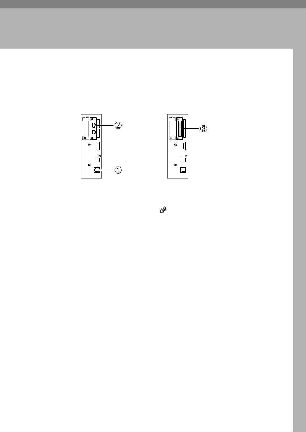
Confirming the Connection
When the IEEE 1394
interface board (optional)
is installed.
1. 10BASE-T/100BASE-TX port
Port for connecting the 10BASE-T or
100BASE-TX cable
2. IEEE 1394 ports (optional)
Ports for connecting the IEEE 1394 interface cable
3. Wireless LAN port (optional)
Port for using the wireless LAN
When the
wireless LAN board (optional)
is installed.
AJL131S
Note
❒ The optional IEEE 1394 interface board
and the IEEE 802.11b interface unit
cannot be installed at the same time.
❒ The position of the port differ depend-
ing on the machine type.
9
Page 16
Connecting and Setting Up
2
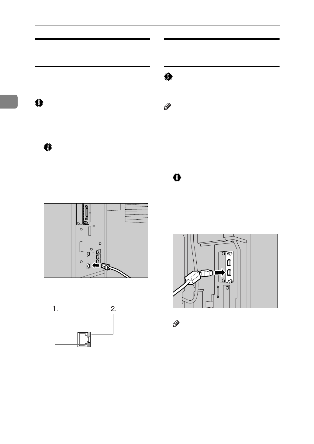
Connecting to the Ethernet Interface
The network interface board supports
10BASE-T or 100BASE-TX connections.
Important
❒ Before making the connection, touch
the metallic part to ground yourself.
A Turn off the main power switch.
Important
❒ Make sure the main power is off.
See “Turning On the Power”,
General Settings Guide.
B Connect the Ethernet interface cable
to the 10BASE-T/100BASE-TX port.
Connecting to the IEEE 1394 Interface
Important
❒ Before making the connection, touch
the metallic part to ground yourself.
Note
❒ Use the interface cable supplied
with the optional IEEE 1394 interface board.
❒ Make sure the interface cable is not
looped.
A Turn off the main power switch.
Important
❒ Make sure the main power is off.
See “Turning On the Power”,
General Settings Guide.
B Connect the IEEE 1394 interface
cable to the IEEE 1394 ports.
C Turn on the main power switch.
1. Indicator (green)
Remains green when the machine is
properly connected to the network.
2. Indicator (yellow)
Turns yellow when 100 BASE-TX is
operating. Turns off when 10 BASE-T
is operating.
10
ZZZ023S
AJL019S
AJO005S
Note
❒ Two interface ports are available
for connecting the IEEE 1394 interface cable. Either is suitable.
❒ If you have an interface cable
with a ferrite core, connect the
end nearest to the ferrite core to
the machine.
❒ The position of the port differ
depending on the machine type.
C Turn on the main power switch.
Page 17
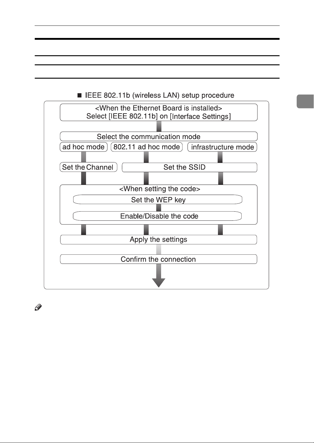
Using the IEEE 802.11b (Wireless LAN)
Setting IEEE 802.11b (Wireless LAN)
Confirming the Connection
2
Note
❒ Select [802.11 Ad hoc] mode when connecting Windows XP as a wireless LAN
client using Windows XP standard driver or utilities, or when not using the
infrastructure mode.
11
Page 18
Connecting and Setting Up
2
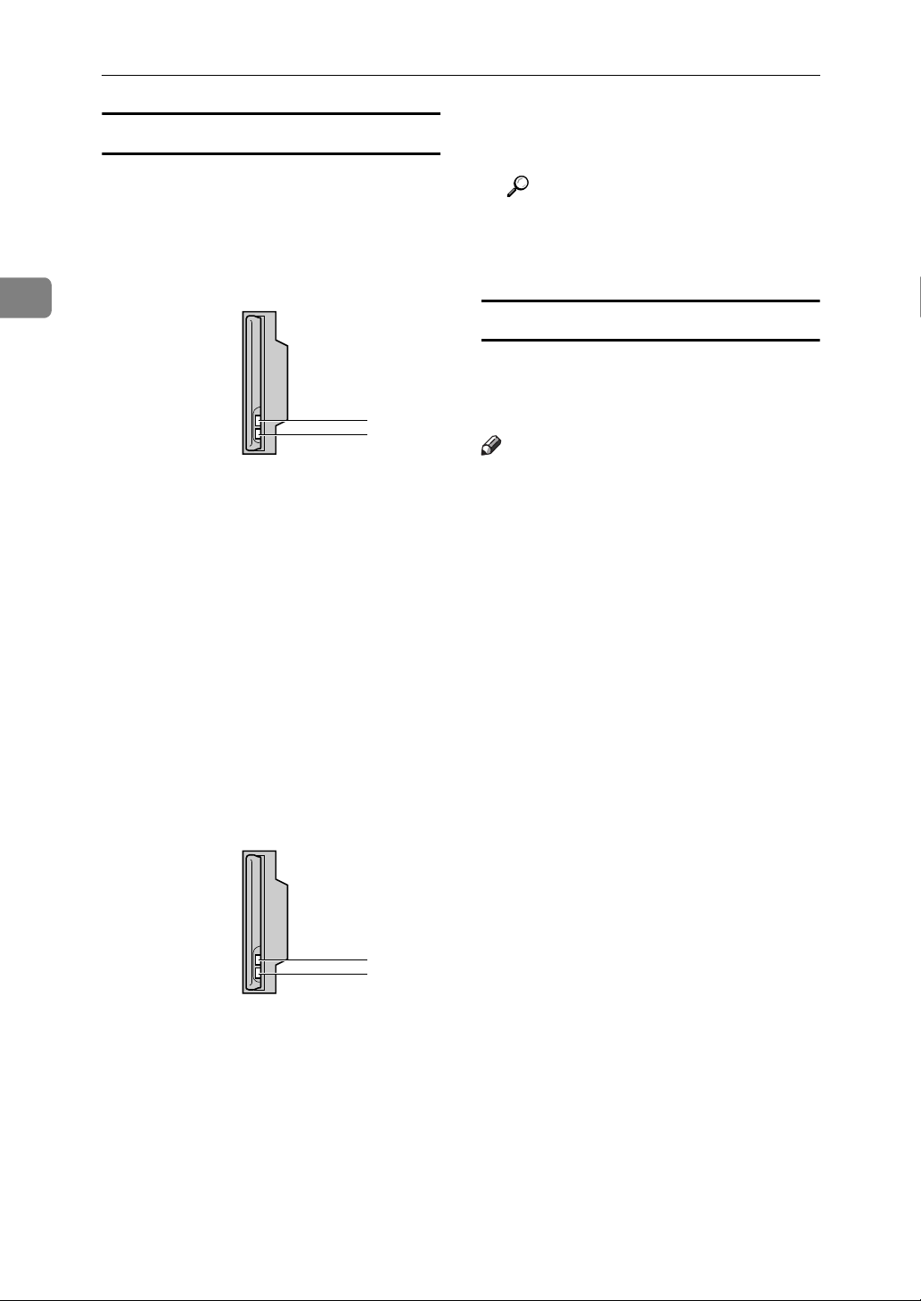
Confirming the Connection
A Make sure the LED of the IEEE
802.11b interface unit is lit.
❖ When using in infrastructure mode
1
2
ZZZ024S
1. If [LAN Type] on the [Interface Set-
tings]/[Network] screen is not set to
[IEEE 802.11b], it does not light, even
if the main power is on.
2. If it is connected properly to the
network, the LED is green when in
infrastructure mode. If the LED is
blinking, the machine is searching
for devices.
❖ When using in ad hoc mode/802.11
ad hoc mode
B Print the configuration page to
verify settings.
Reference
For more information about
printing a configuration page,
see Printer Reference.
Checking the machine's radio wave status
When using in infrastructure mode,
you can check the machine's radio
wave status using the control panel.
Note
❒ To check the radio wave status,
press [IEEE 802.11b] under [LAN
Type] on the [Network] screen.
A Press the {User Tools/Counter/Inquiry}
key.
B Press [System Settings].
C Press [Interface Settings].
D Press [IEEE 802.11b].
E Press [Wireless LAN Signal].
The machine's radio wave status
appears.
1. If the IEEE 802.11b interface unit
is working, it is lit in orange.
2. If it is connected properly to the
network, the LED is green when in
ad hoc mode or 802.11 ad hoc mode.
If the LED is blinking, the machine
is searching for devices. The LED
will light after a few seconds.
12
F After checking radio wave status,
press [Exit].
G Press the {User Tools/Counter/Inquiry}
key to return to the User Tools /
1
2
ZZZ024S
Counter / Inquiry menu.
Page 19
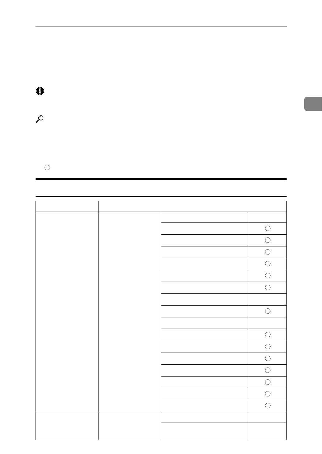
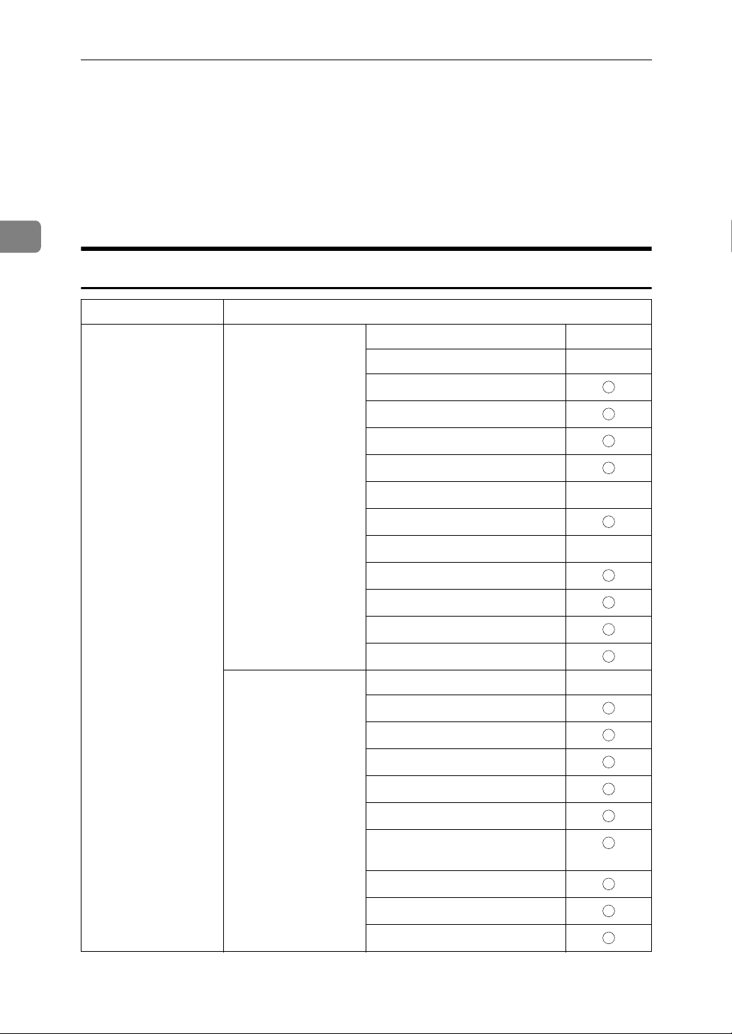
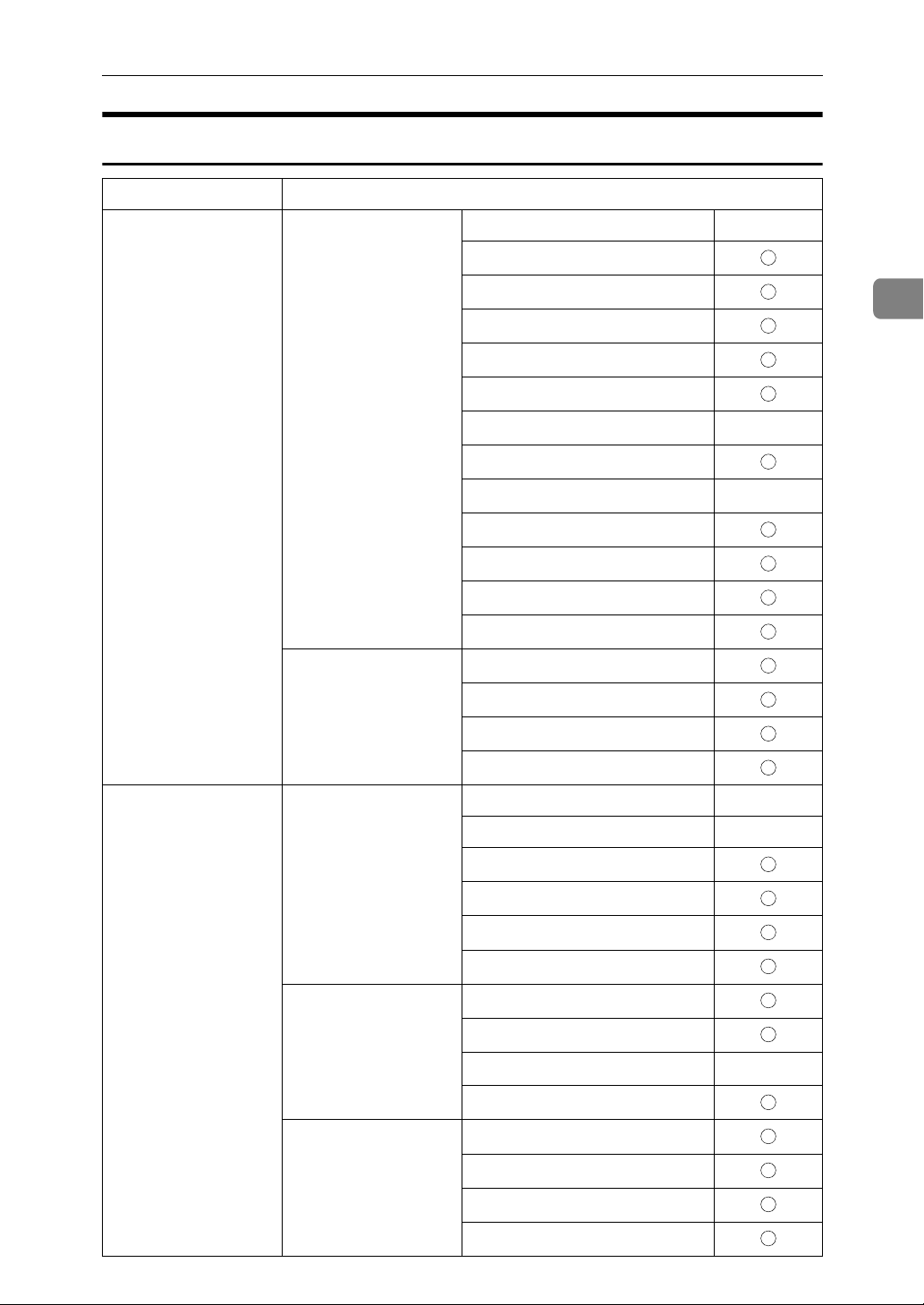
Setting Up the Machine on a Network
Setting Up the Machine on a Network
This section describes the network settings you can change with User Tools (System
Settings). Make settings according to functions you want to use and the interface to
be connected.
Important
❒ These settings should be made by the systems administrator, or after consulting
with the systems administrator.
Reference
For details about settings, see p.34 “Interface Settings”
❖ Viewing the Information Displayed in the List
$ These items must be set to use the function. Be sure to set them before
attempting to use the corresponding function.
These items must be set if required.
Printer/LAN-Fax
2
Interface Settings
Ethernet Interface Settings/
Network
See p.34 “Network”.
IP Address $
Gateway Address
DNS Configuration
DDNS Configuration
Domain Name
WINS Configuration
NW Frame Type
LAN Type
Ethernet Speed
Effective Protocol
NCP Delivery Protocol
SMB Computer Name
SMB Work Group
Permit SNMP V3 Communication
Permit SSL / TLS Communication
*2
*3
$
$
IEEE 1394
(IP over 1394)
Interface Settings/
IEEE 1394
See p.36 “IEEE 1394”.
*1
Host Name
Machine Name
IP Address $
IP over 1394 $
13
Page 20
Connecting and Setting Up
Interface Settings
2
IEEE 1394
(IP over 1394)
IEEE 802.11b
(wireless LAN)
Interface Settings/
IEEE 1394
*1
See p.36 “IEEE 1394”.
Interface Settings/
Network
See p.34 “Network”.
Interface Settings/
Network
See p.34 “Network”.
WINS Configuration
DDNS Configuration
Host Name
Domain Name
Gateway Address
DNS Configuration
Effective Protocol
*3
$
NCP Delivery Protocol
IP Address $
Gateway Address
DNS Configuration
DDNS Configuration
Domain Name
WINS Configuration
NW Frame Type
LAN Type
*2
$
14
Ethernet Speed
Effective Protocol
*3
NCP Delivery Protocol
SMB Computer Name
SMB Work Group
Permit SNMP V3 Communication
Permit SSL / TLS Communication
Host Name
Machine Name
Interface Settings/
IEEE 802.11b
*2
Communication Mode $
SSID Setting
See p.37 “IEEE
802.11b”.
Channel
WEP (Encryption) Setting
Transmission Speed
*1
Appears when the optional IEEE 1394 interface board is installed.
*2
Appears when the optional IEEE 802.11b interface unit is installed.
If Ethernet and IEEE 802.11b (wireless LAN) are both connected to the machine, the
selected interface has priority.
*3
Check [Effective] is selected for TCP/IP.
$
Page 21

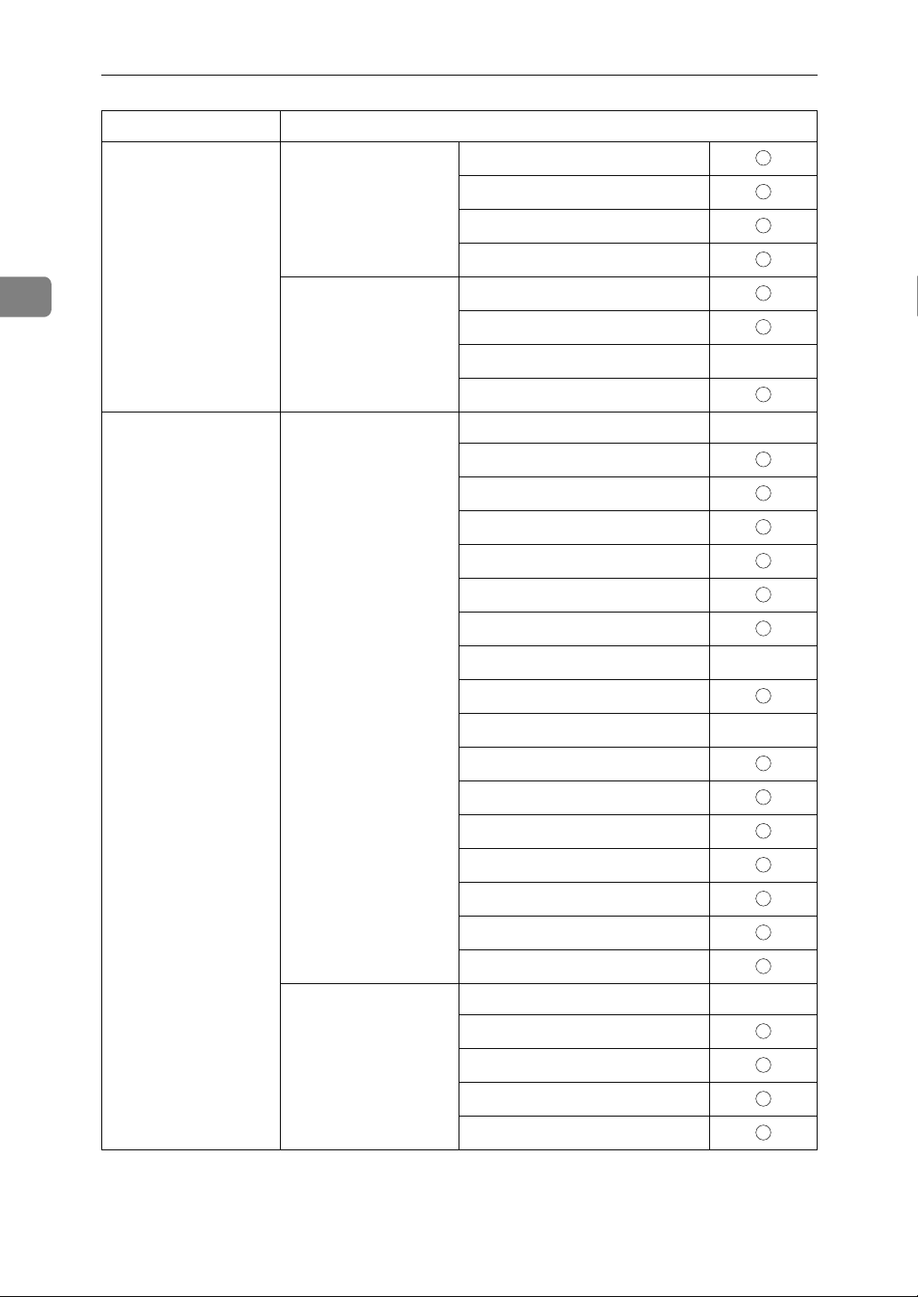
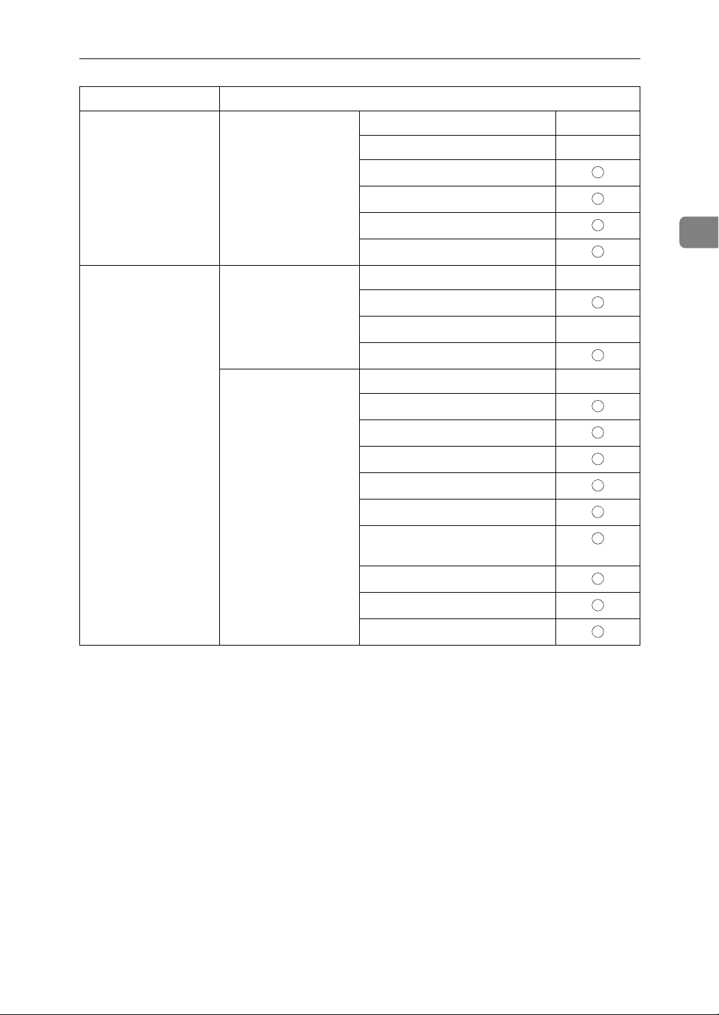
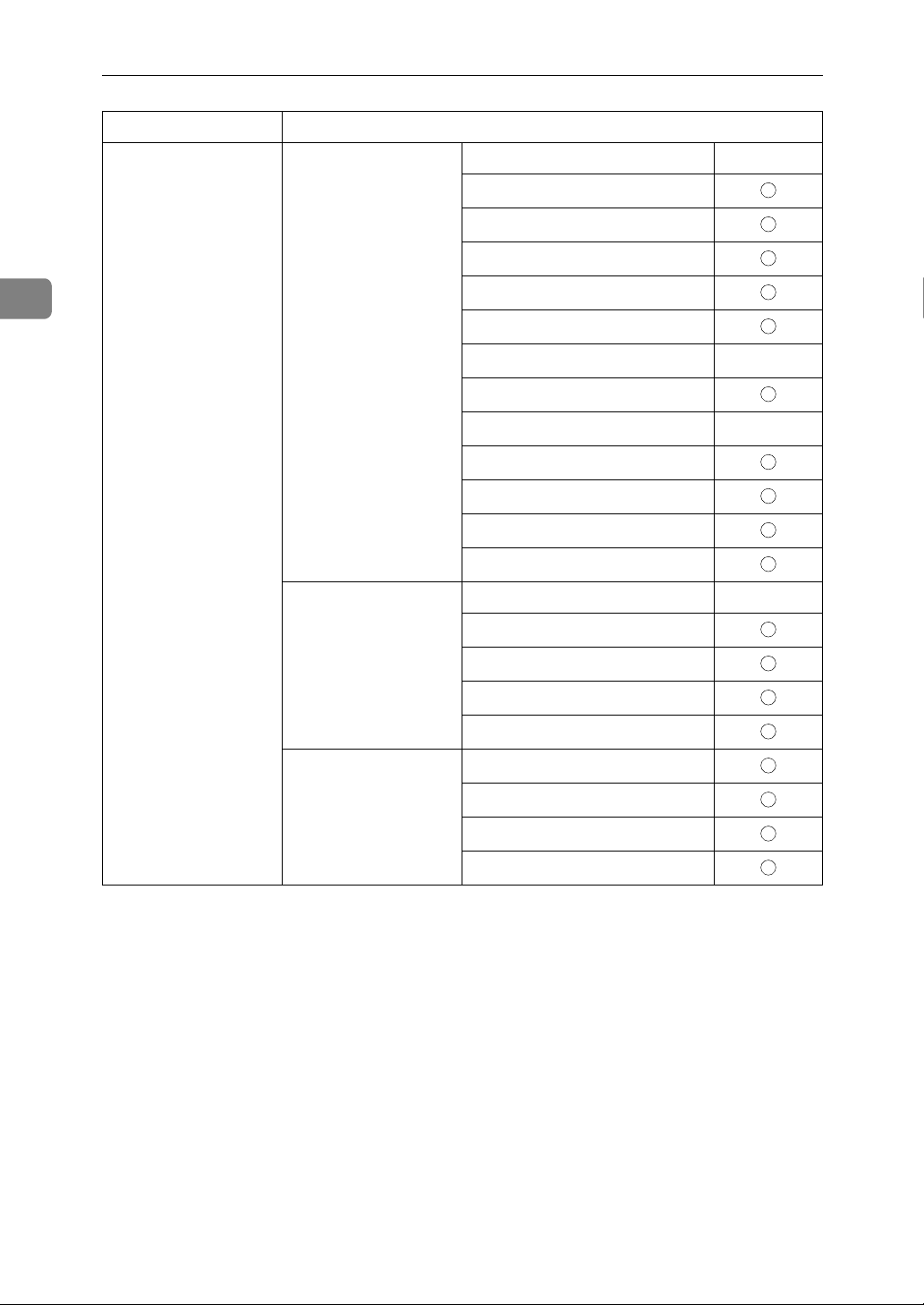
Internet Fax
Interface Settings
Setting Up the Machine on a Network
Ethernet Interface Settings/
Network
See p.34 “Network”.
File Transfer
See p.39 “File Transfer”.
IP Address $
Gateway Address $
DNS Configuration
DDNS Configuration
Domain Name
WINS Configuration
LAN Type
*2
$
Ethernet Speed
Effective Protocol
*5
$
NCP Delivery Protocol
Permit SNMP V3 Communication
Permit SSL / TLS Communication
Host Name
SMTP Server
*3
$
SMTP Authentication
POP before SMTP
2
IEEE 1394
(IP over 1394)
Interface Settings/
IEEE 1394
*1
See p.36 “IEEE 1394”.
Reception Protocol
POP3 / IMAP4 Settings
*4
*6
Administrator's E-mail Address
E-mail Communication Port
*8
*7
$
$
E-mail Reception Interval
Max. Reception E-mail Size
E-mail Storage in Server
Program / Change / Delete Email Message
Program / Change / Delete Subject
Fax E-mail Account
*3 *4
$
IP Address $
IP over 1394 $
DDNS Configuration
WINS Configuration
15
Page 22
Connecting and Setting Up
Interface Settings
2
IEEE 1394
(IP over 1394)
Interface Settings/
IEEE 1394
*1
See p.36 “IEEE 1394”.
Interface Settings/
Network
See p.34 “Network”.
File Transfer
See p.39 “File Transfer”.
Host Name
Domain Name
Gateway Address $
DNS Configuration
Effective Protocol
*5
$
NCP Delivery Protocol
SMTP Server
*3
$
SMTP Authentication
POP before SMTP
Reception Protocol
POP3 / IMAP4 Settings
*4
*6
Administrator's E-mail Address
E-mail Communication Port
*7
*8
*4
$
$
E-mail Reception Interval
Max. Reception E-mail Size
E-mail Storage in Server
Program / Change / Delete Email Message
Program / Change / Delete Subject
Fax E-mail Account
*3 *4
$
16
Page 23
Interface Settings
Setting Up the Machine on a Network
IEEE 802.11b
(wireless LAN)
IEEE 802.11b
(wireless LAN)
Interface Settings/
Network
See p.34 “Network”.
Interface Settings/
IEEE 802.11b
*2
See p.37 “IEEE
802.11b”.
IP Address $
Gateway Address $
DNS Configuration
WINS Configuration
DDNS Configuration
Domain Name
LAN Type
*2
$
Ethernet Speed
Effective Protocol
*5
$
NCP Delivery Protocol
Permit SNMP V3 Communication
Permit SSL / TLS Communication
Host Name
Communication Mode $
SSID Setting
Channel
WEP (Encryption) Setting
2
Transmission Speed
File Transfer
See p.39 “File Transfer”.
SMTP Server
SMTP Authentication
*3
POP before SMTP
Reception Protocol
POP3 / IMAP4 Settings
Administrator's E-mail Address
E-mail Communication Port
*7
E-mail Reception Interval
Max. Reception E-mail Size
E-mail Storage in Server
Program / Change / Delete Email Message
Program / Change / Delete Subject
Fax E-mail Account
*1
Appears when the optional IEEE 1394 interface board is installed.
*4
*3 *4
$
$
*6
*8
*4
$
$
17
Page 24
2
Connecting and Setting Up
*2
Appears when the optional IEEE 802.11b interface unit is installed.
If Ethernet and 802.11b (wireless LAN) are both connected to the machine, the selected
interface has priority.
*3
Minimum settings required to use transmission.
*4
Minimum settings required to use reception.
*5
Check[Effective] is selected for TCP/IP.
*6
If you select [On] for [POP before SMTP], select this function also.
*7
If you select [On] for [POP before SMTP], check the port number for [POP3].
*8
If you select [On] for [SMTP Authentication], select this function also.
Interface Settings
Ethernet Interface Settings/
Network
See p.34 “Network”.
File Transfer
See p.39 “File Transfer”.
IP Address $
Gateway Address $
DNS Configuration
DDNS Configuration
Domain Name
WINS Configuration
LAN Type
Ethernet Speed
Effective Protocol
NCP Delivery Protocol
Permit SNMP V3 Communication
Permit SSL / TLS Communication
Host Name
SMTP Server $
SMTP Authentication
POP before SMTP
*2
*3
$
$
18
POP3 / IMAP4 Settings
Administrator's E-mail Address
E-mail Communication Port
Program / Change / Delete Email Message
Program / Change / Delete Subject
Scanner Recall Interval Time
Number of Scanner Recalls
*4
*5
Page 25
Interface Settings
Setting Up the Machine on a Network
IEEE 1394
(IP over 1394)
IEEE 1394
(IP over 1394)
Interface Settings/
IEEE 1394
See p.36 “IEEE 1394”.
Interface Settings/
Network
See p.34 “Network”.
File Transfer
See p.39 “File Transfer”.
*1
IP Address $
IP over 1394 $
DDNS Configuration
WINS Configuration
Host Name
Domain Name
Gateway Address $
DNS Configuration
Effective Protocol
NCP Delivery Protocol
SMTP Server $
SMTP Authentication
POP before SMTP
POP3 / IMAP4 Settings
Administrator's E-mail Address
Reception Protocol
*3
*4
*5
$
2
Program / Change / Delete Email Message
Program / Change / Delete Subject
Scanner Recall Interval Time
Number of Scanner Recalls
19
Page 26
Connecting and Setting Up
Interface Settings
2
IEEE 802.11b
(wireless LAN)
Interface Settings/Network
See p.34 “Network”.
Interface Settings/
IEEE 802.11b
*2
See p.37 “IEEE
802.11b”.
IP Address $
Gateway Address $
DNS Configuration
DDNS Configuration
Domain Name
WINS Configuration
LAN Type
*2
$
Ethernet Speed
Effective Protocol
*3
$
NCP Delivery Protocol
Permit SNMP V3 Communication
Permit SSL / TLS Communication
Host Name
Communication Mode $
SSID Setting
Channel
WEP (Encryption) Setting
20
Transmission Speed
IEEE 802.11b
(wireless LAN)
File Transfer
See p.39 “File Trans-
SMTP Server $
SMTP Authentication
fer”.
POP before SMTP
Reception Protocol
*4
Administrator's E-mail Address
E-mail Communication Port
*5
Program / Change / Delete Email Message
Program / Change / Delete Subject
Scanner Recall Interval Time
Number of Scanner Recalls
*1
Appears when the optional IEEE 1394 interface board is installed.
*2
Appears when the optional IEEE 802.11b interface unit is installed.
If Ethernet and 802.11b (wireless LAN) are both connected to the machine, the selected
interface has priority.
*3
Check [Effective] is selected for TCP/IP.
*4
If you select [On] for [POP before SMTP], select this function as well.
*5
If you select [On] for [POP before SMTP], check the port number for [POP3].
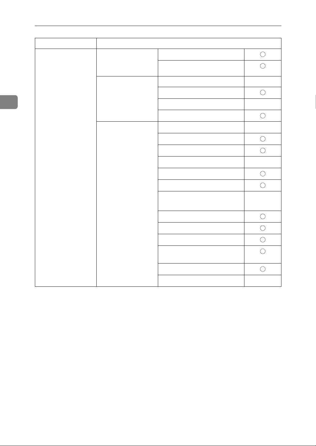
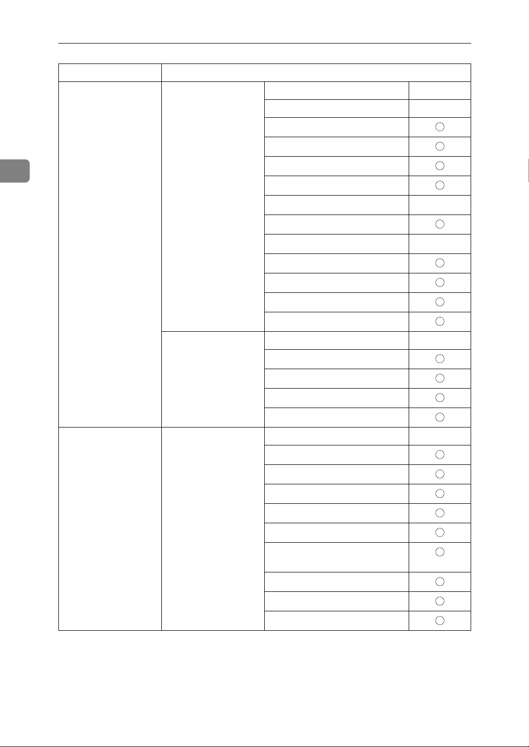
Page 27

Scan to Folder
Interface Settings
Setting Up the Machine on a Network
Ethernet Interface Settings/
Network
See p.34 “Network”.
File Transfer
See p.39 “File Transfer”.
IP Address $
Gateway Address $
DNS Configuration
DDNS Configuration
Domain Name
WINS Configuration
LAN Type
Ethernet Speed
Effective Protocol
NCP Delivery Protocol
Host Name
Permit SNMP V3 Communication
Permit SSL / TLS Communication
Default User Name / Password
(Send)
Scanner Recall Interval Time
*2
*3
$
$
2
IEEE 1394
(IP over 1394)
Interface Settings/
IEEE 1394
See p.36 “IEEE 1394”.
Interface Settings/
Network
See p.34 “Network”.
File Transfer
See p.39 “File Transfer”.
*1
Number of Scanner Recalls
IP Address $
IP over 1394 $
DDNS Configuration
WINS Configuration
Host Name
Domain Name
Gateway Address $
DNS Configuration
Effective Protocol
NCP Delivery Protocol
Default User Name / Password
(Send)
Scanner Recall Interval Time
Number of Scanner Recalls
*3
$
21
Page 28
Connecting and Setting Up
Interface Settings
2
IEEE 802.11b
(wireless LAN)
Interface Settings/
Network
See p.34 “Network”.
Interface Settings/
IEEE 802.11b
See p.37 “IEEE
802.11b”.
*2
IP Address $
Gateway Address $
DNS Configuration
DDNS Configuration
Domain Name
WINS Configuration
LAN Type
Ethernet Speed
Effective Protocol
Permit SNMP V3 Communication
Permit SSL / TLS Communication
Host Name
Communication Mode $
SSID Setting
Channel
WEP (Encryption) Setting
*2
*3
$
$
Transmission Speed
File Transfer
See p.39 “File Transfer”.
*1
Appears when the optional IEEE 1394 interface board is installed.
*2
Appears when the optional IEEE 802.11b interface unit is installed.
Default User Name / Password
(Send)
Scanner Recall Interval Time
Number of Scanner Recalls
If Ethernet and IEEE 802.11b (wireless LAN) are both connected to the machine, the
selected interface has priority.
*3
Check [Effective] is selected for TCP/IP.
22
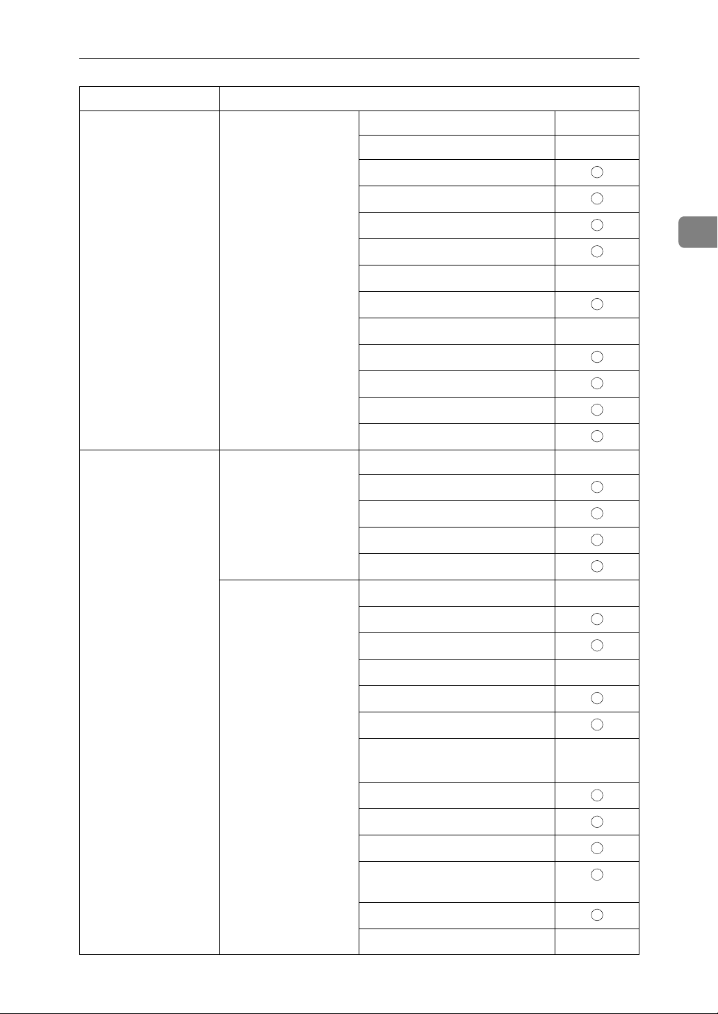
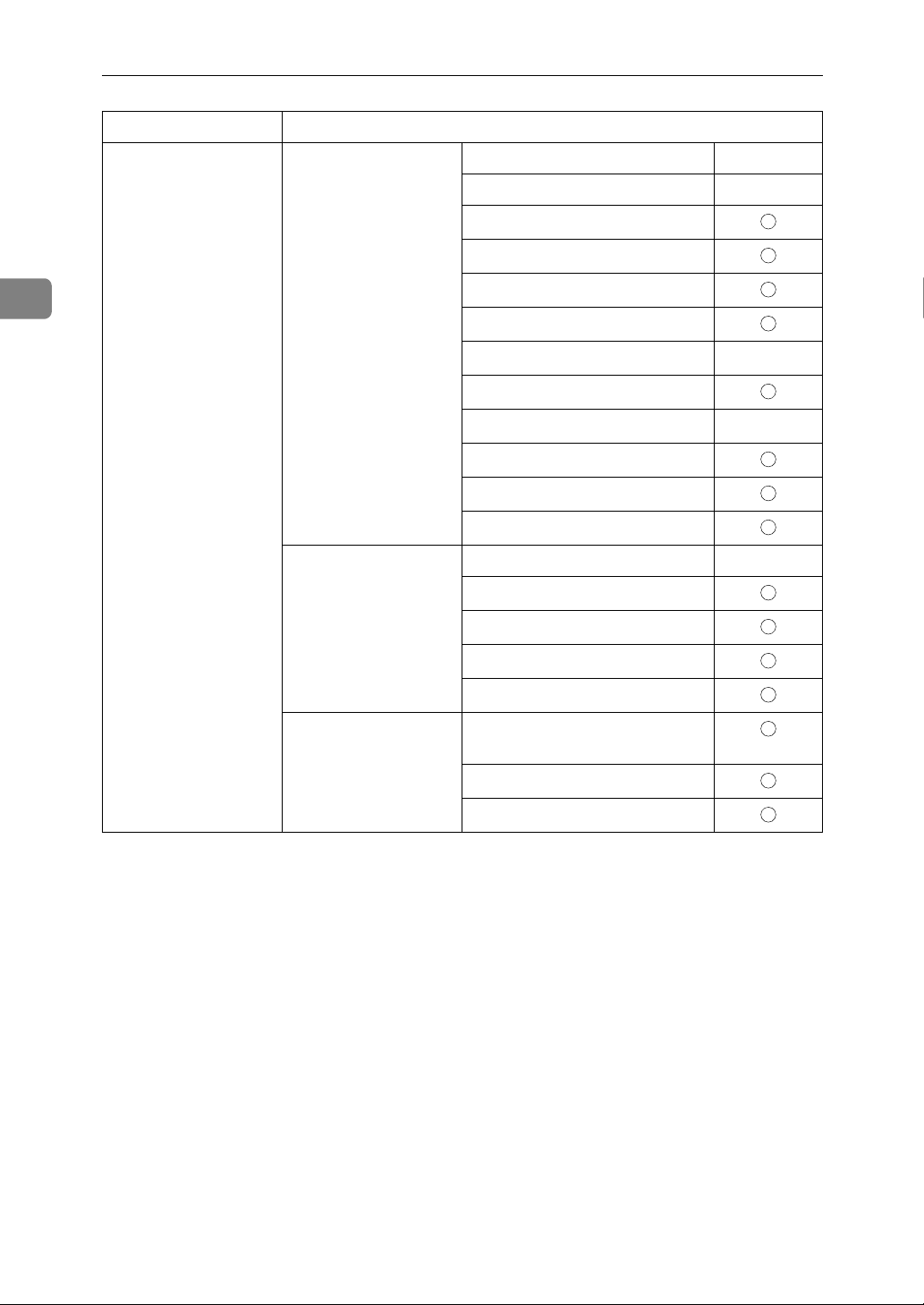
Page 29
Network Delivery Scanner
Interface Settings
Setting Up the Machine on a Network
Ethernet Interface Settings/
Network
See p.34 “Network”.
File Transfer
See p.39 “File Transfer”.
IP Address $
Gateway Address
DNS Configuration
DDNS Configuration
Domain Name
WINS Configuration
LAN Type
Ethernet Speed
Effective Protocol
NCP Delivery Protocol
Permit SNMP V3 Communication
Permit SSL / TLS Communication
Host Name
Delivery Option
Fax RX File Transmission
Scanner Recall Interval Time
*2
*4
*3
$
$
2
IEEE 1394
(IP over 1394)
Interface Settings/
IEEE 1394
See p.36 “IEEE 1394”.
Interface Settings/
Network
See p.34 “Network”.
File Transfer
See p.39 “File Transfer”.
*1
Number of Scanner Recalls
IP Address $
IP over 1394 $
DDNS Configuration
WINS Configuration
Host Name
Domain Name
Gateway Address
DNS Configuration
Effective Protocol
NCP Delivery Protocol
Delivery Option
Fax RX File Transmission
Scanner Recall Interval Time
Number of Scanner Recalls
*4
*3
$
23
Page 30
Connecting and Setting Up
Interface Settings
2
IEEE 802.11b
(wireless LAN)
Interface Settings/
Network
See p.34 “Network”.
Interface Settings/
IEEE 802.11b
*2
See p.37 “IEEE
802.11b”.
IP Address $
Gateway Address
DNS Configuration
DDNS Configuration
Domain Name
WINS Configuration
LAN Type
*2
$
Ethernet Speed
Effective Protocol
*4
$
NCP Delivery Protocol
Permit SNMP V3 Communication
Permit SSL / TLS Communication
Host Name
Communication Mode $
SSID Setting
Channel
WEP (Encryption) Setting
Transmission Speed
File Transfer
See p.39 “File Transfer”.
Delivery Option
Fax RX File Transmission
*3
Scanner Recall Interval Time
Number of Scanner Recalls
*1
Appears when the optional IEEE 1394 interface board is installed.
*2
Appears when the optional IEEE 802.11b interface unit is installed.
If Ethernet and IEEE 802.11b (wireless LAN) are both connected to the machine, the
selected interface has priority.
*3
When delivery option is set to [On], make sure the IP address is set.
*4
Check [Effective] is selected for TCP/IP.
24
Page 31

Network TWAIN Scanner
Interface Settings
Setting Up the Machine on a Network
Ethernet Interface Settings/
Network
See p.34 “Network”.
IEEE 1394
(IP over 1394)
Interface Settings/
IEEE 1394
See p.36 “IEEE 1394”.
*1
IP Address $
Gateway Address
DNS Configuration
DDNS Configuration
Domain Name
WINS Configuration
LAN Type
Ethernet Speed
Effective Protocol
NCP Delivery Protocol
Permit SNMP V3 Communication
Permit SSL / TLS Communication
Host Name
IP Address $
IP over 1394 $
DDNS Configuration
*2
*3
$
$
2
IEEE 802.11b
(wireless LAN)
Interface Settings/
Network
See p.34 “Network”.
Interface Settings/
Network
See p.34 “Network”.
WINS Configuration
Host Name
Domain Name
Gateway Address
DNS Configuration
Effective Protocol
NCP Delivery Protocol
IP Address $
Gateway Address
DNS Configuration
DDNS Configuration
Domain Name
WINS Configuration
LAN Type
Ethernet Speed
*3
*2
$
$
25
Page 32

Connecting and Setting Up
Interface Settings
IEEE 802.11b
(wireless LAN)
Interface Settings/
Network
See p.34 “Network”.
Effective Protocol
NCP Delivery Protocol
Permit SNMP V3 Communication
Permit SSL / TLS Communication
*3
$
2
Host Name
Interface Settings/
IEEE 802.11b
See p.37 “IEEE
802.11b”.
*1
Appears when the optional IEEE 1394 interface board is installed.
*2
Appears when the optional IEEE 802.11b interface unit is installed.
*2
Communication Mode $
SSID Setting
Channel
WEP (Encryption) Setting
Transmission Speed
If Ethernet and 802.11b (wireless LAN) are both connected to the machine, the selected
interface has priority.
*3
Check [Effective] is selected for TCP/IP.
Document Server
Interface Settings
Ethernet Interface Set-
tings/Network
See p.34 “Network”.
IP Address $
Gateway Address
DNS Configuration
26
DDNS Configuration
Domain Name
WINS Configuration
LAN Type
Ethernet Speed
Effective Protocol
NCP Delivery Protocol
Permit SNMP V3 Communication
Permit SSL / TLS Communication
Host Name
*2
*3
$
$
Page 33

Interface Settings
Setting Up the Machine on a Network
IEEE 1394
(IP over 1394)
IEEE 802.11b
(wireless LAN)
Interface Settings/
IEEE 1394
*1
See p.36 “IEEE 1394”.
Interface Settings/
Network
See p.34 “Network”.
Interface Settings/
Network
See p.34 “Network”.
IP Address $
IP over 1394 $
DDNS Configuration
WINS Configuration
Host Name
Domain Name
Gateway Address
DNS Configuration
Effective Protocol
*3
$
NCP Delivery Protocol
IP Address $
Gateway Address
DNS Configuration
DDNS Configuration
Domain Name
WINS Configuration
2
LAN Type
*2
Ethernet Speed
Effective Protocol
*3
NCP Delivery Protocol
Permit SNMP V3 Communication
Permit SSL / TLS Communication
Host Name
Interface Settings/
IEEE 802.11b
*2
Communication Mode $
SSID Setting
See p.37 “IEEE
802.11b”.
Channel
WEP (Encryption) Setting
Transmission Speed
*1
Appears when the optional IEEE 1394 interface board is installed.
*2
Appears when the optional IEEE 802.11b interface unit is installed.
If Ethernet and IEEE 802.11b (wireless LAN) are both connected to the machine, the
selected interface has priority.
*3
Check [Effective] is selected for TCP/IP.
$
$
27
Page 34

Connecting and Setting Up
2
Network Configuration
Any change you make with User
Tools remains in effect even if the
main power switch or operation
switch is turned off, or the {Energy
Saver} or {Clear Modes} key is pressed.
Configuring the network using the control panel
Note
❒ Operations for System Settings are
different from normal operations.
After using User Tools, press the
{User Tools/Counter/Inquiry} key to
exit.
❒ When [User Authentication Manage-
ment] is set, operations are not pos-
sible with the machine unless a
valid user name and password is
entered. For details about user authentication, consult administrator.
F Press [Exit].
G Press the {User Tools/Counter/Inquiry}
key.
Note
❒ You can also exit by pressing
[Exit] on the User Tools main
menu.
A Press the {User Tools/Counter/Inquiry}
key.
Note
❒ The machine will be offline dur-
ing setting.
B Press [System Settings].
C Press [Interface Settings] or [File Trans-
fer].
D Select the required menu, and then
press the desired key.
E Change settings by following the
instructions on the display panel,
and then press [OK].
Note
❒ To cancel changes made to set-
tings and return to theSystem
Settings menu, press [Cancel].
28
Page 35

Setting Up the Machine on a Network
Configuring the network using other utilities
As well as using the control panel to make network settings, utilities such as a
Web Image Monitor and SmartDeviceMonitor for Admin can also be used. The
following table shows available settings:
Note
❒ Indicates machine settings can be changed.
❒ - Indicates the setting cannot be changed from that device.
2
29
Page 36

Connecting and Setting Up
Name on the control panel
Web Image
Monitor
SmartDeviceMon-
itor for
Admin
telnet
2
Interface
Settings
Network IP Ad-
dress
Gateway Address
DNS
Configuration
DDNS Configuration -
Domain
Name
WINS
Configuration
Auto-Obtain (DHCP)
Specify IP Ad-
dress
Sub-net
Mask
Auto-Obtain (DHCP) -
Specify VDNS
Server 1
VDNS
Server 2
VDNS
Server 3
Auto-Obtain (DHCP) -
Specify V Do-
main
Name
On VPrima-
ry WINS
Server
-
-
-
-
-
30
Effective
Protocol
VSecondary WINS
Server
Scope ID -
Off -
TCP/IP -
NetWare
SMB
AppleTalk
-
*1
*2
Page 37

Name on the control panel
Setting Up the Machine on a Network
SmartDe-
Web Image
Monitor
viceMon-
itor for
Admin
telnet
Interface
Settings
Network NW
Frame
Type
NCP Delivery Protocol
SMB Computer Name -
SMB Work Group -
Ethernet Speed - - -
LAN
Type
Ping Command - - -
Permit
SNMP V3
Communication
Permit
SSL / TLS
Communication
Auto Select -
Ethernet II -
Ethernet 802.2 -
Ethernet 802.3 -
Ethernet SNAP -
Ethernet -
IEEE 802.11b -
Encryption Only - -
Encryption / Clear Text
Ciphertext Only - - -
Ciphertext Priority - - -
Ciphertext / Clear Text
---
---
2
Host Name
Machine Name -
IEEE 1394 IP Ad-
dress
DDNS Configuration -
Host Name -
Domain
Name
Auto-Obtain (DHCP) -
Specify IP Ad-
dress
Sub-net
Mask
Auto-Obtain (DHCP) - -
Specify Domain
Name
-
-
-
31
Page 38

Connecting and Setting Up
Name on the control panel
Web Image
Monitor
SmartDeviceMon-
itor for
Admin
telnet
2
Interface
Settings
IEEE 1394 WINS
Configuration
IP over
1394
SCSI print
(SBP-2)
Bidirectional
SCSI print
IEEE
802.11b
Communication
Mode
On Primary
WINS
Server
Secondary WINS
Server
Scope ID -
Off -
Active -
Inactive -
Active -
Inactive -
Active -
Inactive -
802.11 Ad hoc -
Ad hoc -
Infrastructure -
-
-
32
File
Transfer
SSID Setting -
Channel -
WEP (Encryption)
Setting
Wireless LAN Signal - - -
Transmission
Speed
Return to Defaults - - -
Print List - - -
Delivery Option - - -
Capture Server IP Address - - -
Fax RX File Transmission - - -
WEP Active -
Inactive -
Encryption -
Auto - -
11Mbps Fixed - -
5.5Mbps Fixed - -
2Mbps Fixed - -
1Mbps Fixed - -
Page 39

Name on the control panel
Setting Up the Machine on a Network
SmartDe-
Web Image
Monitor
viceMon-
itor for
Admin
telnet
File
Transfer
SMTP Server - -
SMTP Authentication - -
POP before SMTP - -
2
Reception Protocol - -
POP3 Setting - -
Administrator's E-mail Address - -
E-mail Communication Port - -
E-mail Reception Interval - -
Max. Reception E-mail Size - -
E-mail Storage in Server - -
Default User Name / Password (Send) - -
Program / Change / Delete E-mail Message - - -
Program / Change / Delete Subject - - -
Scanner Recall Interval Time - - -
Number of Scanner Recalls - - -
Fax E-mail Account - - -
Auto Specify Sender Name - - -
*1
You can make the TCP/IP settings if SmartDeviceMonitor for Admin is communicating with the machine using IPX/SPX.
*2
You can make the IPX/SPX settings if SmartDeviceMonitor for Admin is communicating with the machine using TCP/IP.
33
Page 40

Connecting and Setting Up
2
Interface Settings
Network
❖ IP Address
Before using this machine in the network environment, you must configure the IP address and subnet mask.
•Auto-Obtain (DHCP)
•Specify
When you select [Specify], enter
the [IP Address]and [Sub-net Mask]
as “xxx.xxx.xxx.xxx”(“x” indicates a number).
• IP Address: 011.022.033.044
•Sub-net Mask:
000.000.000.000
Note
❒ Default: Auto-Obtain (DHCP)
❒ If you use the interface for Eth-
ernet and IEEE 1394 (IP over
1394) at the same time, settings
must be made carefully. See
p.133 “Using DHCP”.
❒ If you install the optional IEEE
1394 interface board and use the
IEEE 1394 interface, you must
set the address of the domain,
different from the [IP Address] of
[IEEE 1394]. If you intend to set
the address for the same domain, set a different value for
the [Sub-net Mask].
❒ When you select [Specify], be
sure not to set the same [IP Ad-
dress] as that of another ma-
chines on the network.
❒ The physical address (MAC ad-
dress) also appears.
❖ Gateway Address
A gateway is a connection or interchange
point between two networks. Configure
the gateway address for the router or
host computer used as a gateway.
• Gateway Address:
000.000.000.000
34
Note
❒ Default: 000.000.000.000
❖ DNS Configuration
Make settings for the DNS server.
•Auto-Obtain (DHCP)
•Specify
When you select [Specify], enter
the DNS Server IP address as
“xxx.xxx.xxx.xxx”(“x” indicates a number).
• VDNS Server 1:
000.000.000.000
• VDNS Server 2:
000.000.000.000
• VDNS Server 3:
000.000.000.000
Note
❒ Default: Auto-Obtain (DHCP)
❖ DDNS Configuration
You can specify the DDNS settings.
•Active
•Inactive
❖ Domain Name
You can specify the domain name.
•Auto-Obtain (DHCP)
•Specify
•Domain Name
❖ WINS Configuration
You can specify the WINS server
settings.
•On
If [On] is selected, enter the [Primary
WINS Server
Server
xxx”(“x” indicates a number).
If DHCP is in use, specify the
[Scope ID].
• Primary WINS Server
•Secondary WINS Server
•Scope ID
•Off
]
and [Secondary WINS
]
IP address as “xxx.xxx.xxx.
Page 41

Setting Up the Machine on a Network
Limitation
❒ Enter a [Scope ID] using up to 31
alphanumeric characters.
Note
❒ Default: Off
❖ Effective Protocol
Select the protocol to use in the
network.
• TCP/IP:Effective/Invalid
• NetWare:Effective/Invalid
• SMB:Effective/Invalid
• AppleTalk:Effective/Invalid
Note
❒ Default: TCP/IP: Effective, Net-
Ware: Effective, SMB: Effective,
AppleTalk: Effective
❖ NCP Delivery Protocol
Select the protocol for NCP delivery:
•IPX Priority
• TCP / IP Priority
•IPX Only
• TCP / IP Only
❖ NW Frame Type
Select the frame type when you
use NetWare.
•Auto Select
•Ethernet II
• Ethernet 802.2
• Ethernet 802.3
• Ethernet SNAP
Note
❒ Default: Auto Select
❖ SMB Computer Name
Specify the SMB computer name.
❖ SMB Work Group
Specify the SMB work group.
❖ Ethernet Speed
Set the access speed for networks.
Select a speed that matches your
network environment. [Auto Select]
should usually be selected.
•Auto Select
• 100Mbps Full Duplex
• 100Mbps Half Duplex
• 10Mbps Full Duplex
•10Mbps Half Duplex
Note
❒ Default: Auto Select
❖ LAN Type
When you have installed the optional IEEE 802.11b interface unit,
select interface, IEEE 802.11b (wireless LAN) or Ethernet.
•Ethernet
• IEEE 802.11b
Note
❒ Default: Ethernet
❒ Appears when the optional IEEE
802.11b interface unit is installed.
❒ If Ethernet and IEEE 802.11b
(wireless LAN) are both connected to the machine, the selected
interface takes precedence.
❖ Ping Command
Check the network connection with
ping command using given IP address.
Note
❒ If you fail to connect to the net-
work, check the following, and
then retry the ping command.
• Check TCP/IP of the printer
is active.
• Check that the machine with
assigned IP address is connected to the network.
• There is a possibility that same
IP address is used for the specified equipment.
❖ Permit SNMP V3 Communication
Set the encrypted communication
of SNMP v3.
•Encryption Only
• Encryption / Clear Text
Note
❒ If you set to [Encryption Only],
you need to set password for
the machine.
2
35
Page 42

Connecting and Setting Up
2
❖ Permit SSL / TLS Communication
Set the encrypted communication
of SSL/TLS.
• Ciphertext Only
• Ciphertext Priority
• Ciphertext / Clear Text
Note
❒ Default: Ciphertext Priority
❒ If you set to [Encryption Only],
you need to install the server
authentification for the machine.
❖ Host Name
Specify the host name.
❖ Machine Name
Specify the machine name.
IEEE 1394
Preparation
You must install the optional IEEE
1394 interface board in the machine.
❖ IP Address
When you connect the machine to
a network using the IEEE 1394 interface, you must configure the IP
address and subnet mask.
•Auto-Obtain (DHCP)
•Specify
When you select [Specify], enter
the [IP Address] and [Sub-net
Mask] as “xxx.xxx.xxx.xxx”(“x”
indicates a number).
• IP Address: 011.022.033.044
•Sub-net Mask:
000.000.000.000
Note
❒ Default: Auto-Obtain (DHCP)
❒ If you use the interface for Eth-
ernet and IEEE 1394 (IP over
1394) at the same time, settings
must be made carefully. See
p.133 “Using DHCP”
36
❒ When you use the IEEE 1394 in-
terface on a network, you cannot use the Ethernet interface in
the same domain. To use both
interfaces in the same domain,
set different values for the [Sub-
net Mask].
❒ The physical address (EUI-64)
also appears.
❖ DDNS Configuration
You can specify the DDNS settings.
•Active
•Inactive
❖ Host Name
Specify the host name.
❖ Domain Name
Make settings for the domain name.
•Auto-Obtain (DHCP)
•Specify
•Domain Name
❖ WINS Configuration
You can specify the WINS server
settings.
•On
If [On] is selected, specify the
[Primary WINS Server] and [Secondary WINS Server] IP address as
“xxx.xxx.xxx.xxx” (“xxx” indicates a number).
If DHCP is in use, specify the
[Scope ID].
• Primary WINS Server
•Secondary WINS Server
•Scope ID
•Off
Limitation
❒ Enter [Scope ID] using up to 31
alphanumeric characters.
Note
❒ Default: Off
Page 43

Setting Up the Machine on a Network
❖ IP over 1394
When you use the IP over 1394
function of the IEEE 1394 interface
to connect the machine to the network, or you print from computer
with the IP over 1394 driver, you
must specify [Active]for [IP over
1394].
•Active
•Inactive
Limitation
❒ Printing with IP over 1394 is pos-
sible under Windows Me/XP
and Windows Server 2003
Note
❒ Default: Active
❖ SCSI print (SBP-2)
When you print using the SCSI
print client function supported by
Windows 2000/XP, or Windows
Server 2003, you must set [SCSI
print (SBP-2)].
IEEE 802.11b
Preparation
You must install the optional IEEE
802.11b interface unit into the ma-
chine.
Note
❒ Be sure to make all settings simul-
taneously.
2
•Active
•Inactive
Limitation
❒ The IEEE 1394 interface can be
used when Windows 2000 Service Pack 1 or later is installed. If
the Service Pack is not installed,
only one SCSI print device is
connectable via 1394 bus.
Note
❒ Default: Active
❖ Bidirectional SCSI print
Specifies the printer's response
mode etc. for status requests when
using the IEEE 1394 interface.
•On
•Off
Note
❒ Default: On
❒ If this is set to [Off], bidirectional
communication will not work.
37
Page 44

Connecting and Setting Up
2
❖ Communication Mode
Specifies the communication mode
of the wireless LAN.
• 802.11 Ad hoc
•Ad hoc
• Infrastructure
Note
❒ Default: 802.11 Ad hoc
❖ SSID Setting
Specifies SSID to distinguish the
access point in infrastructure
mode or 802.11 ad hoc mode.
Limitation
❒ The characters that can be used
are ASCII 0x20-0x7e (32 bytes).
Note
❒ Default: blank (ASSID)
❒ If blank is specified in 802.11b
ad hoc mode or ad hoc mode,
“ASSID” appears.
❖ Channel
Specifies a channel when you select
802.11b ad hoc mode or ad hoc mode.
Note
❒ Default: 11
❒
The following channels are available:
• Metric version: 1-14
• Inch version: 1-11
❖ WEP (Encryption) Setting
Specifies the encryption of the
IEEE 802.11b (wireless LAN). If
this is set to [Active], you must enter the WEP key.
•WEP
❖ Wireless LAN Signal
Shows the radio wave conditions
of the access point connected in infrastructure mode.
Note
❒ Radio wave status is displayed
when you press [Wireless LAN
Signal].
❖ Transmission Speed
Specifies the communication speed
of the IEEE 802.11b (wireless LAN).
•Auto
•11Mbps Fixed
• 5.5Mbps Fixed
•2Mbps Fixed
•1Mbps Fixed
Note
❒ Default: Auto
❖ Return to Defaults
You can return the IEEE 802.11b
(wireless LAN) settings to their defaults.
•No
•Yes
Print List
You can check items related to the
network in use.
Reference
For details about printing, see p.38
“Printing the Interface Settings”.
Printing the Interface Settings
38
•Active
•Inactive
•Encryption
10 alphanumeric characters
must be entered for 64 bit, 26
characters for 128 bit.
Note
❒ Default: Inactive
The configuration page shows the
current network settings and network
information.
A Press the {User Tools/Counter/Inquiry}
key.
B Press [System Settings].
C Press [Interface Settings].
Page 45

Setting Up the Machine on a Network
D Press [Print List].
E Press the {Start} key.
The configuration page is printed.
F Press [Exit].
G Press the {User Tools/Counter/Inquiry}
key.
Note
❒ You can also exit by pressing
[Exit] on the User Tools main
menu.
File Transfer
❖ Delivery Option
Enables or disables sending stored
or scanned documents via the
ScanRouter V2 Professional delivery server.
•On
• Main Delivery Server IP Ad-
dress
• Sub Delivery Server IP Ad-
dress
•Off
Note
❒ Default: Off
❒ Set this option when specifying
whether or not to use ScanRouter
V2 Professional. If you do, you
will have to re-register I/O devices in ScanRouter V2 Professional.
❖ Fax RX File Transmission
• Setting per Line
Specifies whether or not received fax documents are sent
to ScanRouter V2 Professional
for each fax line.
• Line 1:Deliver to Server/Do
not Deliver
• Line 2:Deliver to Server/Do
not Deliver
• E-mail:Deliver to Server/Do
not Deliver
Note
❒ Default: Do not Deliver
• Print at Delivery
Specifies whether or not received fax documents sent to
ScanRouter V2 Professional
should also be printed at the
same time.
•Print
•Do not Print
Note
❒ Default: Do not Print
• File to Deliver
Specifies whether all received
fax documents or only received
fax documents that include delivery codes (documents with an
ID and SUB/SEP code) are sent
to ScanRouter V2 Professional.
• File with Dlvry Code
• All Files
Note
❒ Default: All Files
2
❖ Capture Server IP Address
Specify the capture server IP address.
Note
❒ This setting appears when the
media link board is installed,
and that the capture function is
being used by the ScanRouter
V2 Proffessional.
• Dlvry Failure File
• Print File
• Delete File
If a received fax document cannot
be sent to ScanRouter V2 Professional, it is stored in memory. To
print a stored file, select [Print
File]; to delete, select [Delete File].
39
Page 46

Connecting and Setting Up
2
Note
❒
If the machine can send the
data to ScanRouter V2 Professional, it does so automatically.
❒ If you delete the data, you will
not be able to distribute or
print it.
❖ SMTP Server
Specify the SMTP server name.
If DNS is in use, enter the host name.
If DNS is not in use, enter the
SMTP server IP address.
•Server Name
• Port No.:25
Limitation
❒ Enter the [Server Name] using up
to 127 alphanumeric characters.
Spaces cannot be used.
Note
❒ Enter [Change], enter [Port No.]
between 1 and 65535 using the
number keys, and then press
the [#]key.
❒
SMTP server shares the same port
number with Direct SMTP server.
Limitation
❒ Enter [User Name] using up to
191 alphanumeric characters.
Spaces cannot be used.
❒ Depending on the SMTP server
type, "realm" must be specified.
Add "@" after the user name, as
in "user name@realm".
❒ Enter [Password] using up to 63
alphanumeric characters. Spaces cannot be used.
❒ Enter the user name and pass-
word to be set for [Administra-
tor's E-mail Address] when using
Internet Fax.
Note
❒ Default: Off
❒ [Encryption]-[Auto]: If the authenti-
cation method is PLAIN, LOGIN,
CRAM-MD5, or DIGEST-MD5.
❒ [Encryption]-[On]: If the authenti-
cation method is CRAM-MD5
or DIGEST-MD5.
❒ [Encryption]-[Off]: If the authenti-
cation method is PLAIN, or
LOGIN.
❖ SMTP Authentication
You can configure SMTP authentication (PLAIN, LOGIN, CRAMMD5, DIGEST-MD5).
Authentication prevents unauthorized access, by making users enter a
user name and password when
sending e-mail to the SMTP server.
•On
If the SMTP server requires authentication, set [SMTP Authenti-
cation] to [On], and then specify
[User Name],[E-mail Address],
[Password], and [Encryption].
•User Name
• E-mail Address
• Password
•Encryption
Auto/On/Off
40
•Off
❖ POP before SMTP
You can configure POP authentication (POP before SMTP).
Authentication prevents unauthorized access, by authenticating
with the POP server before sending e-mail to the SMTP server.
•On
To enable POP server authentication before sending e-mail via
the SMTP server, set [POP before
SMTP] to [On].
E-mail is sent to the SMTP server after the time specified for
[Wait Time after Auth.] has
elapsed.
• Wait Time after Auth.: 300msec
•User Name
• E-mail Address
•Password
Page 47

Setting Up the Machine on a Network
•Off
Limitation
❒ Enter [User Name] using up to 63
alphanumeric characters. Spaces cannot be used.
❒ Enter [Password] using up to 63
alphanumeric characters. Spaces cannot be used.
Note
❒ Default: Off
❒ Using the number keys, you can
set [Wait Time after Auth.] from
zero to 10,000 milliseconds, in
increments of one millisecond.
❒ If you select [On], enter [Server
Name] in [POP3 / IMAP4 Settings].
Also, check the port number for
[POP3] in [E-mail Communication
Port].
❖ Reception Protocol
Specify Reception Protocol for receiving Internet faxes.
•POP3
•IMAP4
•SMTP
Note
❒ Default: POP3
❖ POP3 / IMAP4 Settings
Specify the POP3 or IMAP4 [Server
Name] for receiving Internet faxes.
The specified POP3 server name is
used for [POP before SMTP].
If DNS is in use, enter the host name.
If DNS is not in use, enter the POP3
or IMAP4 server IP address.
•Server Name
•Encryption
•Auto
•On
•Off
Limitation
❒
Enter POP3 or IMAP4 [Server Name
using up to 127 alphanumeric characters. Spaces cannot be used.
Note
❒[Encryption]-[Auto]: Password en-
cryption is automatically set according to the POP server settings.
❒ [Encryption]-[On]: Encrypt pass-
word.
❒ [Encryption]-[Off]: Do not encrypt
password.
❖ Administrator's E-mail Address
On e-mailed scanned documents,
if the sender is not specified this
appears as the sender’s address.
This can be used as the sender with
SMTP authentication for Internet
Fax. If [On] is selected for [SMTP Au-
thentication] be sure to enter the ad-
ministrator's e-mail address here.
This can be used as the destination
for data transmission result cc emails, as well as the destination for
data communication management
e-mail.
Limitation
❒ Enter up to 128 alphanumeric
characters.
❖ E-mail Communication Port
Specify the [POP3], [IMAP4], and
[SMTP] port numbers for receiving
Internet faxes.
The specified POP3 port number is
used for [POP before SMTP].
•POP3: 110
Note
❒ Default: POP3/110
❒ Enter [Change], enter a port
number between 1 and 65535
using the number keys, and
then press the [#] key.
❖ E-mail Reception Interval
Specify, in minutes, the time limit
for receiving Internet faxes via
]
POP3 or IMAP4 server.
• On: 15 minute(s)
•Off
2
41
Page 48

Connecting and Setting Up
2
Note
❒ Default: On/15 minute(s)
❒ If [On] is selected, the number of
times can be set from 2 to 1440
in increments of one minute, using the number keys.
❖ Max. Reception E-mail Size
Specify the [Max. Reception E-mail
Size] for receiving Internet faxes.
Note
❒ Default: 2MB
❒ Using the number keys, enter a
size from 1 to 50 MB in increments of one megabyte.
❖ E-mail Storage in Server
You can specify whether or not to
store received Internet fax e-mails
on the POP3 or IMAP4 server.
•Off
•All
•Errors Only
Note
❒ Default: Off
Note
❒ When set to [On], the specified
e-mail address is used for the
[From:] box. If the sender's email address is not set , or the
e-mail address is not registered , e-mail cannot be sent.
❒ When set to [Off], the adminis-
trator's e-mail address or the
machine's e-mail address will
be used for the [From:] box.
❖ Program / Change / Delete E-mail Mes-
sage
You can program, change, or delete the e-mail message used when
sending an Internet fax or scan file
as an attachment.
• Program / Change
• Delete
Note
❒ Enter a name using up to 20 al-
phanumeric characters.
❒ Enter up to five lines of text.
Each line can consist of up to 80
alphanumeric characters.
❖ Default User Name / Password (Send)
You can specify the user name and
password required when sending
scan file directly to a shared folder
on a computer running Windows,
or to an FTP server.
• SMB User Name
• SMB Password
•FTP User Name
• FTP Password
•NCP User Name
• NCP Password
Limitation
❒ Enter up to 128 alphanumeric
characters.
❖ Auto Specify Sender Name
Set name of the sender when sending an e-mail.
•On
42
•Off
❖ Program / Change / Delete Subject
You can program, change, or delete
the subject used when sending an
Internet fax or scan file as an attachment.
• Program / Change
• Delete
Note
❒ Enter a subject using up to 20 al-
phanumeric characters.
❖ Fax E-mail Account
Specify [E-mail Address], [User
Name], and [Password] for receiving
Internet faxes.
• Fax Mail Reception
• E-mail Address
•User Name
•Password
Page 49

Setting Up the Machine on a Network
Limitation
❒ Enter an e-mail address using up
to 128 alphanumeric characters.
❒ Enter a user name using up to
64 alphanumeric characters.
❒ Enter a password using up to 64
alphanumeric characters.
❖ Scanner Recall Interval Time
Specifies the interval the machine
waits before resending scan file, if
they cannot be sent to the delivery
server or mail server.
Note
❒ Default: 300 seconds
❒ The interval time can be set from
60 to 900 seconds in one second
increments, using the number
keys.
❒ This setting is for the scanner
function.
❖ Number of Scanner Recalls
Sets a maximum number of times
scan file is resent to the delivery
server or mail server.
•On: 3 time(s)
•Off
Note
❒ Default: On/3 time(s)
❒ If [On] is selected, the number of
times can be set from 1 to 99 using the number keys.
❒ This setting is for the scanner
function.
A Press the {User Tools/Counter/Inquiry}
key.
B Press [System Settings].
C Press [File Transfer].
D Press [T Next].
The next screen appears.
E Press [Program / Change / Delete E-mail
Message].
Programming an e-mail message
A Press [*Not Programmed].
B Press [Change], and then enter
the name.
Reference
For more information about
entering text, see “Entering
Text”, General Settings Guide.
C Press [OK].
D Press [Edit], and then enter the
text.
To start a new line, press [OK] to
return to the e-mail message
screen, and then press [T] in [Se-
lect Line to Edit:].
E Press [OK].
The e-mail message screen appears.
F Press [OK].
2
Programming, changing, or deleting an e-mail message
Limitation
❒ Enter a name using up to 20 alpha-
numeric characters.
❒ Enter up to five lines of text. Each
line can consist of up to 80 alphanumeric characters.
Changing an e-mail message
A Select the e-mail message to
change.
B If you want to change the sub-
ject, press [Change].
C Change the subject, and then
press [OK].
D Press [U] or [T] to select the
line to change.
43
Page 50

Connecting and Setting Up
2
E If you want to change the text,
press [Edit].
F Change the text, and then press
[OK].
G Press [OK].
Deleting an e-mail message
A Press [Delete].
B Select the e-mail message to
delete.
The confirmation message
about deleting appears.
C To delete the data, press [Yes].
F Press [Exit].
G Press [Exit].
H Press the {User Tools/Counter/In-
quiry} key.
Note
❒ You can also exit by pressing
[Exit] on the User Tools main
menu.
Programming, changing, or deleting a subject
E Press [Program / Change / Delete Sub-
ject].
Programming a subject
A Press [*Not Programmed], and
then enter the text.
Reference
For more information about
entering text, see “Entering
Text”, General Settings Guide.
B Press [OK].
Changing a subject
A Select the subject to change.
B Enter the text.
C Press [OK].
Deleting a subject
A Press [Delete].
B Select the subject to delete.
The confirmation message
about deleting appears.
C To delete the subject, press
[Yes].
Limitation
❒ Enter a subject using up to 20 alpha-
numeric characters.
Note
❒ [Urgent] and [High] are programmed
as the e-mail subjects.
A Press the {User Tools/Counter/Inquiry}
key.
B Press [System Settings].
C Press [File Transfer].
D Press [TNext]. The next screen ap-
pears.
44
F Press [Exit].
G Press [Exit].
H Press the {User Tools/Counter/Inquiry}
key.
You can also exit by pressing [Exit]
on the User Tools main menu.
Page 51

LDAP Server Settings
Program the LDAP server to find up
e-mail destinations in the LDAP server Address Book directly. This function is possible when sending scan
files by e-mail using the scanner or
fax function.
Before using this function
To start an LDAP search, make sure
that the items listed below are set. For
other items, check your environment
and make any necessary changes.
•Server Name
•Search Base
•Port No.
• Search Conditions
• Authentication method selection
Note
❒ For authentication method, se-
lect from [High Security], [On], or
[Off].
• User Name/Password
The settings above differ depending on server environment. Check
your environment and make any
necessary changes.
Note
❒ To use the LDAP server in Admin-
istrator Tools, select [On] under
LDAP server.
❒ This function supports LDAP Ver-
sion 2.0 and 3.0. Ver 2.0 does not
support High Security authentication.
LDAP Server Settings
Program/Change/Delete LDAP Server
To enter Program/Change/Delete
LDAP Server
A Press the {User Tools/Counter/Inquiry}
key.
B Press [System Settings].
C Press [Administrator Tools], and then
press [TNext] twice.
D Press [Program / Change / Delete LDAP
Server].
To program/change the LDAP
server
A Select the LDAP server you want
to program or change.
When programming the server, select [*Not Programmed].
B Set each item as necessary.
2
45
Page 52

Connecting and Setting Up
2
To finish programming/changing the
LDAP Server
A Press [Change] after setting each
item.
B Press [Exit].
C Press [Exit].
D Press the {User Tools/Counter/Inquiry}
key.
Programming the LDAP Server
To enter an identification name
Register a name for the LDAP server
that will appear on the server selection
screen of the LDAP search operation.
A Press [Change] under [Identification
Name].
B Enter the server’s identification
name.
C Press [OK].
To enter a server name
To delete the programmed LDAP
server
A Press [Delete].
B Select the LDAP server you want
to delete.
C Press [Yes].
Register the LDAP server’s host name
or IP address.
A Press [Change] under [Server Name].
B Enter the LDAP server name.
C Press [OK].
To enter the search base
Select a route folder to start the search
from e-mail addresses registered in
the selected folder are search targets.
A Press [Change] under [Search Base].
B Enter the search base.
46
Page 53

LDAP Server Settings
Note
❒
For example, if the search target is
the sales department of ABC company, enter “dc=sales department,
o=ABC”. (In this example, the description is for an active directory.
“dc” is for the organization unit,
and “o” is for the company.)
❒
Search base registration may be
required depending on your server environment. When registration is required, unspecified
searches will result in error. Check
you server environment and enter
any required specifications.
C Press [OK].
To enter a port number
Specify the port number for communicating with the LDAP server. Specify a port that is compliant with your
environment.
❒ SSL setting must be enabled on
this machine. For details, consult
your network administrator.
To set authentication
To make a search request to the LDAP
server, use the administrator account
for authentication.
For details about the administrator
account, see “To enter the user name
and password”.
A Press [TNext].
B Press [On] or [High Security] under
[Authentication].
2
A Press [Change] under [Port No.].
B Enter the port number using the
number keys, and then press [#].
Note
❒ When SSL is set to [On], the port
number automatically changes
to “636”.
To start SSL communication
Use SSL to communicate with the
LDAP server.
A Press [On].
Note
❒ To use SSL, the LDAP server
must support SSL.
❒ When SSL is set to [On], the port
number automatically changes
to “689”.
Note
❒ Authentication settings must
comply with your server’s authentication settings. Check
your server settings before setting this machine.
❒ [High Security] is available only
with LDAP Version 3.0.
❒ When [High Security] is selected,
the administrator password is
encrypted before it is sent to the
network. When [On] is selected,
the password is sent without
encryption.
47
Page 54

2
Connecting and Setting Up
To enter the user name and password
When [On] or [High Security] is selected
for the authentication setting, use the
administrator account name and
password. Do not enter the administrator account name and password
when using authentication for each
individual or each search.
❒
You can set the user name and password in this machine’s Address
Book to allow individual authentication access to the LDAP server. Use
Administrator Tools to select the user
name and password you want to use.
For details, see General Manual.
To test the connection
A Press [TNext].
B Press [Change] under [User Name].
C Enter the user name, and then press
[OK].
Note
❒ Procedures for the user name
setting differ depending on
server environment. Check
your server environment before
making the setting.
• Example setting procedures:
Domain Name\User Name
User Name@Domain Name
CN=Name, OU=Department
Name, DC=Server Name
D Press [Change] under [Password].
E Enter the password, and then press
[OK].
Access the LDAP server to check the
proper connection is established.
Check authentication works according to the authentication settings.
A Press [Connection Test].
A connection test is carried out.
B Press [Exit].
Note
❒ If the connection test fails, check
your settings and try again.
❒
This function does not check search
conditions or the search base.
To set search conditions
You can enter an attribute as a typical
search keyword. Using the entered attribute, the function searches the
LDAP server’s Address Book.
A Press [TNext] twice.
B Press [Change] for items you want
to use as search conditions from
the following: [Name], [E-mail Ad-
dress], [Fax Number], [Company
Name], and [Department Name].
48
Note
❒ The user name and password
are required for administrator
access to the LDAP server.
Page 55

LDAP Server Settings
C Enter the attribute you want to
use when searching for e-mail addresses, and then press [OK].
Note
❒ The attribute value may change
depending on the server environment. Check the attribute
value complies with your server
environment before setting it.
❒ You can leave items blank, but
you cannot leave attributes
blank when searching for e-mail
addresses from the LDAP server Address Book.
To set search options
To search the LDAP server data using a
keyword other than prepared keywords
such as Name, E-mail Address, FAX
Number, Company Name, and Department Name, specify the attribute for the
keyword registered in your LDAP server, and the name to be displayed on the
control panel during the search. For example, to search e-mail addresses by
employee number, enter “employeeNo.” in the Attribute field, and “Employee No.” in the key display field.
C Enter the attribute you want to
use when searching for e-mail addresses, and then press [OK].
Note
❒ The attribute value may change
depending on the server environment. Check the attribute
complies with your server environment before setting it.
D Press [Change] under [Key Display].
E Enter the key display, and then
press [OK].
The registered “key display” appears
as a keyword for searching LDAP.
• Without key display registration
• With key display registration
2
A Press [TNext] three times.
B Press [Change] under [Attribute].
Note
❒
The key does not appear on the
search screen unless both “Attribute” and “Key Display” are
registered. Make sure you register
both to use the optional search.
49
Page 56

2
Connecting and Setting Up
50
Page 57

3. Using a Printer Server
Preparing Printer Server
This section explains how to configure
the machine as a Windows network
printer. The machine is configured to
enabling network clients to use it.
When the network printer is connected via SmartDeviceMonitor for Client,
you can set the printing notification
function to notify clients of the results
of their print jobs.
Important
❒ Under Windows 2000, Windows
XP Professional, or Windows Server 2003, to change printer properties in the [Printer] folder, you need
Printer Management access authentication; under Windows NT
4.0, Full Control access authentication. Log on to the file server as an
Administrator or member of the
PowerUsers group.
A Open the [Printers] window from
the [Start] menu.
The [Printers] window appears.
B Click the icon of the machine you
want to use. On the [File] menu,
click [Properties]. The printer
properties appear.
C On the [Sharing] tab, click [Shared
this printer].
D To share the machine with users
using a different version of Windows, click [Additional Drivers...].
Note
❒ If you have installed an alterna-
tive driver by selecting [Share
this printer] during the printer
driver installation, this step can
be ignored.
E Click [OK]. Close the printer prop-
erties.
Printing notification via SmartDeviceMonitor for Client
Follow the procedure below to configure the machine to use the printing
notification function of SmartDeviceMonitor for Client.
Setting the print server
Important
❒ Under Windows 2000, Windows
XP Professional, or Windows Server 2003, to change printer properties in the [Printer] folder, you need
Printer Management access authentication; under Windows NT
4.0, Full Control access authentication. Log on to the file server as an
Administrator or member of the
PowerUsers group.
A From the [Start] button on the task
bar, point to [Programs], point to
[SmartDeviceMonitor for Client], and
then click [Print Server Setting].
The print server setting dialog box
appears.
B Select the [Notify client PCs of print-
out/data-transmission ] check box,
and click [OK].
After print server setting is made, a
dialog box appears. Confirm the
dialog box content, and click [OK].
Click [Cancel] to interrupt the procedure.
51
Page 58

Using a Printer Server
C A dialog box appears for client
setting. Click [OK].
The print server setting is complete. Each client must be set to receive print notification.
Note
❒ Current printing jobs restart
from the beginning after the
spooler pauses briefly.
3
❒ When the expansion function is
not used, the function is automatically set as available.
❒ If you log on using an account
that does not have Administrator privileges, the client may not
be notified.
Setting a Client
A From the [Start] button on the task
bar, point to [Program], point to
[SmartDeviceMonitor for Client], and
then click [Extended Features Set-
tings].
A dialog box for setting the expansion function appears.
B Select the [Notify of printout/data-trans-
mission] check box, and then click
[Detailed Settings].
C Select the [Notify of printout/data-trans-
mission when using print server] check
box on the [Notification Settings]
screen.
D Click [OK].
The dialog box for setting the expansion function closes. The client
setting is completed.
Note
❒ Set the printing notification func-
tion on the printer driver as well
as on SmartDeviceMonitor for
Client.
52
Page 59

Using NetWare
Using NetWare
This section describes the setting procedure for network printers in the
NetWare environment. In the NetWare environment, you can connect
the machine as a “print server” or “remote printer”.
❖ Setting procedure
• When using the machine as a
print server
A Installing SmartDeviceMon-
itor for Admin
B Setting the network interface
board.
C Turning the machine off and
then back on.
• When using the machine as a
remote printer
A Installing SmartDeviceMoni-
tor for Admin.
B Setting the network interface
board.
C Setting NetWare.
D Starting the print server.
Note
❒ The NetWare Client provided by
Novell is required to set the printing environment using SmartDeviceMonitor for Admin under the
following environments:
• NDS mode in Windows 95/98
/Me
• NDS or Bindery mode in Windows 2000/XP, Windows NT
4.0
Reference
For details about installing
SmartDeviceMonitor for Admin, see p.73 “Installing SmartDeviceMonitor for Admin”.
❖ Printers listed by SmartDeviceMoni-
tor for Admin
SmartDeviceMonitor for Admin
lists printers connected to the network. If you cannot identify the
machine you want to configure,
print configuration page, and then
check the machine name.
3
Note
❒ This procedure assumes an envi-
ronment is already prepared for
normal NetWare running the
printing service setting.
❒ The procedure is explained with
the following example settings:
• File server’s name …CAREE
• Print server’s name …PSERV
•Printer’s name …R-PRN
• Queue name …R-QUEUE
❖ Using SmartDeviceMonitor for Admin
To use the machine in a NetWare
environment, use SmartDeviceMonitor for Admin to set the NetWare printing environment.
Setting Up as a Print Server (NetWare 3.x)
Follow the procedure below to connect the machine as a print server using NetWare 3.x.
If TCP/IP and IP address is set, configure using Web Image Monitor.
If IPX is set, configure using NIB Setup Tool.
Setting up using NIB Setup Tool (TCP/IP)
A Log on to the file server as a su-
pervisor or supervisor equivalent.
53
Page 60

Using a Printer Server
3
B Start NIB Setup Tool from the
[Start] menu.
C Click [Wizard], and then click [OK].
D Select the printer you want to con-
figure, and then click [Finish ].
A dialog box prompting you to
perform the remaining configuration tasks in the Web browser appears. Click [OK], and then wait
until Web Image Monitor starts automatically.
E A dialog box for entering the [User
Name] and [Password] appears.
Enter the user name and password, and then click [OK].
Note
❒ For details about the password,
consult your network administrator.
F Click [Configuration] in the left ar-
ea, click [Network], and then click
[NetWare].
• Print Server Name: Enter the NetWare print server name. To use
the interface board as a print
server, enter the name of a print
server that is not active on the file
server. Use up to 47 characters.
• Logon Mode: Specify whether to
designate a file server or NDS
tree when logging on to NetWare.
• File Server Name: When a file
server name is entered here,
only the specified file server is
searched for. This item is mandatory. Use up to 47 characters.
• NDS Tree: To enable NDS mode,
enter the name of the NDS tree
you want to log on to. Use up to
32 alphanumeric characters.
54
• NDS Context Name: To enable
NDS mode, enter the print server
context. Use up to 127 characters.
• Operation mode: Specify whether to use the interface board as a
print server or a remote printer.
• Remote printer number: This
item is effective when the interface board is specified as a remote printer. Enter the same
number as the number of the
printer to be created on the print
server (0 to 254 characters).
• Job Timeout: When the interface
board is used as a NetWare remote
printer, the printer cannot detect
when a print job ends. Therefore,
the printer terminates printing
when a certain period of time has
elapsed since it last received print
data (i.e., when it has not received
print data for a certain period of
time). Specify here this period of
time (3 to 255 seconds). The initial
value is 15 (seconds).
• Frame Type: Select the frame
type from the drop-down menu.
• Print Server Protocol: Select the
protocol for NetWare from the
drop-down menu.
• NCP Delivery Protocol: Select
the protocol for NCP delivery.
G Confirm the settings, and then
click [Apply].
Configuration is now complete.
Wait several before restarting Web
Image Monitor.
Note
❒ To check the configuration is
correct, enter the following
from the command prompt:
F:> USERLIST
❒ If the printer works as config-
ured, the name of the print server appears as a connected user.
Page 61

Using NetWare
❒ If you cannot identify the print-
er you want to configure, check
the printer name against the
configuration page printed
from the printer. For details
about printing a configuration
page, see Printer Reference.
❒ If no printer names appear in the
list, match the frame types of
IPX/SPXs for the computer and
printer. Use the [Network] dialog
box of Windows to change the
frame type of the computer.
Setting up using NIB Setup Tool
(IPX)
A Log on to the file server as a su-
pervisor or supervisor equivalent.
B Start NIB Setup Tool from the
[Start] menu.
H Enter the print server name in the
[Print Server Name:] box, the printer
name in the [Printer Name:] box,
and the print queue name in the
[Print Queue Name] box, and then
click [Next >].
•In the [Print Server Name:] box, enter the name of the NetWare print
server using up to 47 characters.
•In the [Printer Name:] box, enter
the name of the NetWare printer.
•In the [Print Queue Name] box, enter the name of the print queue
to be added to NetWare.
I Check the settings, and then click
[Next >].
The settings are applied, and NIB
Setup Tool quits.
J Turn the printer off and then on
again.
3
C Click [Wizard], and then click [OK].
D Select a printer you want to con-
figure.
E Enter the printer name in the [De-
vice Name:] box and a comment in
the [Comment] box, and then click
[Next >].
F Select the [NetWare] check box,
and then click [Next >].
G Click [Bindery mode], enter the file
server name in the [File Server
Name:] box, and then click [Next >].
In the [File Server Name:] box, enter
the name of the file server in which
a print server is created. You can
also click [Browse...] to browse
through available file servers.
Note
❒ To check that the configuration
is made correctly, enter the following from the command
prompt.
F:> USERLIST
❒ If the printer works as config-
ured, the name of the print server appears as a connected user.
❒ If you cannot identify the print-
er you want to configure, check
the printer name with the configuration page printed from
the printer. For details about
printing a configuration page,
see Printer Reference.
❒ If no printer names appear in the
list, match the frame types of
IPX/SPXs for the computer and
printer. Use the [Network] dialog
box of Windows to change the
frame type of the computer.
55
Page 62

Using a Printer Server
3
Setting Up as a Print Server (NetWare 4.x, 5 / 5.1, 6 / 6.5)
Follow the procedure below to connect the machine as a print server using NetWare 4.x, NetWare 5 / 5.1, or
NetWare 6 / 6.5.
If TCP/IP and IP address is set, configure using Web Image Monitor.
If IPX is set, configure using NIB Setup Tool.
Important
❒ When using the printer as a print
server in NetWare 4.x, NetWare 5
/ 5.1, or NetWare 6 / 6.5, set it to
the NDS mode.
❒ When using NetWare 5 / 5.1 or Net-
Ware 6 / 6.5, set the printer as a print
server.
Note
❒ For details about the password,
consult your network administrator.
F Click [Configuration] in the left ar-
ea, click [Network], and then click
[NetWare].
Note
❒ For details , see p.53 “Setting Up
as a Print Server (NetWare
3.x)”.
G Confirm the settings, and then
click [Apply].
Configuration is now complete.
Wait several minutes before restarting Web Image Monitor.
Setting up using NIB Setup Tool (IPX)
Setting up using NIB Setup Tool (TCP/IP)
A Log on to the file server as an ad-
ministrator or administrator
equivalent.
B Start NIB Setup Tool from the
[Start] menu.
C Click [Wizard], and then click [OK].
D Select the printer you want to con-
figure, and then click [Finish ].
A dialog box prompting you to
perform the remaining configuration tasks in the Web browser appears. Click [OK], and then wait
until Web Image Monitor starts automatically.
E A dialog box for entering the [User
Name] and [Password] appears.
Enter the user name and password, and then click [OK].
A Log on to the file server as an ad-
ministrator or administrator
equivalent.
B Start NIB Setup Tool on the [Start]
menu.
C Click [Wizard], and then click [OK].
D Select the printer you want to con-
figure.
E Enter the printer name in the [De-
vice Name:] box and a comment in
the [Comment] box, and then click
[Next >].
F Select the [NetWare] check box,
and then click [Next >].
G Click [NDS mode], enter the file
server name in the [File Server
Name:] box, the NDS tree name in
the [NDS Tree] box, and the context
in the [NDS Context:] box, and then
click [Next >].
56
Page 63

Using NetWare
In the [File Server Name:] box, enter
the name of the file server in which
a print server is created. You can
also click [Browse...] to browse
through available file servers and
NDS context names.
In the [NDS Tree] box, enter the name
of the NDS tree in which a print server is created using up to 32 alphanumeric characters. Hyphens and
underscores can also be used. You
can also click
through available NDS trees.
For a context, object names are entered from the lowest object with
each object separated by a period.
For example, if you want to create
a print server in NET under DS, enter "NET.DS".
[
Browse...] to browse
H Enter the print server name in the
[Print Server Name:] box, the printer
name in the [Printer Name:] box, the
print queue name in the [Print
Queue Name] box, and the print
queue volume in the [Print Queue
Volume] box, and then click [Next >].
•In the [Print Server Name:] box,
enter the name of the NetWare
print server using up to 47 characters.
•In the [Printer Name:] box, enter
the name of the NetWare printer.
•In [Print Queue Name] box, enter
the print queue volume.
•In [Print Queue Volume], type the
print queue volume. For a volume, object names are entered
from the lowest object with each
object separated by a period.
You can also click [Browse...] to
browse through available volumes.
I Check the settings, and then click
[Next >].
The settings are applied, and NIB
Setup Tool quits.
J Turn the printer off and then on
again.
Note
❒ To check that the configuration
is made correctly, enter the following from the command
prompt.
F:> NLIST USER /A/B
❒ If the printer works as config-
ured, the name of the print server appears as a connected user.
❒ If you cannot identify the print-
er you want to configure, check
the printer name with the configuration page printed from
the printer. For details about
printing a configuration page,
see Printer Reference.
❒ If no printer names appear in
the list, match the frame types
of IPX/SPXs for the computer
and printer. Use the [Network]
dialog box of Windows to
change the frame type of the
computer.
Reference
When using the printer in a
pure IP environment of NetWare 5 / 5.1 or NetWare 6.0, see
p.57 “Using Pure IP in the NetWare 5 / 5.1 or 6 / 6.5 Environment”.
Using Pure IP in the NetWare 5 / 5.1 or 6 / 6.5 Environment
Follow the procedure below to connect the machine as a print server in a
pure IP environment of NetWare 5 /
5.1 or NetWare 6 / 6.5.
If TCP/IP and IP address is set, configure using Web Image Monitor.
If IPX is set, configure using NIB Setup Tool.
3
57
Page 64

Using a Printer Server
3
Important
❒ When creating a queued print server
in a pure IP environment of NetWare 5 / 5.1 or NetWare 6 / 6.5, create a print queue on the file server
using NetWare Administrator.
❒ This printer is not available as a re-
mote printer for use in a pure IP
environment.
❒ To use the printer in a pure IP en-
vironment, set it to TCP/IP.
Setting up using NIB Setup Tool (TCP/IP)
A Log on to the file server as an ad-
ministrator or administrator
equivalent.
B Start NIB Setup Tool from the
[Start] menu.
C Click [Property Sheet], and then
click [OK].
D Select the printer you want to con-
figure, and then click [Finish ].
A dialog box prompting you to
perform the remaining configuration tasks in the Web browser appears. Click [OK], and then wait
until Web Image Monitor starts automatically.
E A dialog box for entering the [User
Name] and [Password] appears.
Enter the user name and password, and then click [OK].
Note
❒ For details about the password,
consult your network administrator.
F Click [Configuration] in the left ar-
ea, click [Network], and then click
[NetWare].
Note
❒ For details , see p.53 “Setting Up
as a Print Server (NetWare
3.x)”.
G Confirm the settings, and then
click [Apply].
Configuration is now complete.
Wait several minutes before restarting Web Image Monitor.
Setting up using NIB Setup Tool (IPX)
A Log on to the file server as an ad-
ministrator or administrator
equivalent.
B Start NIB Setup Tool on the [Start]
menu.
C Click [Property Sheet], and then
click [OK].
D Select a printer you want to con-
figure.
E On the [NetWare] tab, Select [File
Server Mode] or [NDS mode] in the
[Logon Mode] area.
When [File Server Mode] is selected,
the network connection is established based on the string entered
in the [File Server Name(F):] box.
When [NDS mode] is selected, the
network connection is established
based on the string entered in the
[NDS Tree] box.
F In the [Print Server Name:] box, en-
ter the name of the print server.
G In the [File Server Name:] box, enter
the name of the file server in
which a print server is created.
You can also click [Browse...] to
browse through available file servers.
58
Page 65

Using NetWare
H Enter the NDS tree name in the
[NDS Tree] box.
Enter up to 32 alphanumeric characters. Hyphens and underscores
can also be used.
I In the [NDS Context:] box, enter the
context of the print server.
You can also click [Browse...] to
browse through available NDS
trees and NDS contexts.
For a context, object names are entered from the lowest object with
each object separated by a period.
For example, if you want to create
a print server in Net under DS, enter "NET.DS".
J In the [Print Server Operation Mode]
area, click [As Print Server].
K Click [OK] to close the [NIB Setup
Tool] dialog box.
Setting up using NWadmin
A From Windows, start NWadmin.
For details about NWadmin, see
the NetWare manuals.
B Select the object in which the
print queue is located in the directory tree, and then click [Create] on
the [Object] menu.
E In the [Print Queue Volume] box,
click [Browse].
F In the [Available objects] box, click
the volume in which the print
queue is created, and then click
[OK].
G Check the settings, and then click
[Create].
H Select the object in which the
printer is located, and then click
[Create] on the [Object] menu.
I In the [Class of new object] box,
click [Printer], and then click [OK].
For NetWare 5, click [Printer (Non
NDPS)].
J In the [Printer name] box, enter the
printer name
K Select the [Define additional proper-
ties] check box, and then click
[Create].
L Click [Assignments], and then click
[Add] in the [Assignments] area.
M In the [Available objects] box, click
the queue you, and then click
[OK].
N Click [Configuration], click [Parallel]
in the [Printer type] list, and then
click [Communication].
O Click [Manual load] in the [Commu-
nication type] area, and then click
[OK].
P Check the settings, and then click
[OK].
3
C In the [Class of new object] box, click
[Print Queue], and then click [OK].
D In the [Print Queue Name] box, enter
the name of the print queue.
Q Select a context specified using
NIB Setup Tool, and then click
[Create] on the [Object] menu.
59
Page 66

Using a Printer Server
3
R In the [Class of new object] box, click
[Print Server], and then click [OK]. For
NetWare 5, click [Print Sever (Non
NDPS)].
S In the [Print Server Name] box, enter
the print server name.
Use the same print server name
specified using NIB Setup Tool.
T Select the [Define additional proper-
ties] check box, and then click
[Create].
U Click [Assignments], and then click
[Add] in the [Assignments] area.
V In the [Available objects] box, click
the queue you created, and then
click [OK].
W Check the settings, and then click
[OK].
X Start the print server by entering
the following from the console of
the NetWare server.
If the print server is in operation,
quit and restart it.
❖ To exit
CAREE: unload pserver
❖ To start
Setting up using NIB Setup Tool (TCP/IP)
A Log on to the file server as a su-
pervisor or supervisor equivalent.
B Start NIB Setup Tool from the
[Start] menu.
C Click [Property Sheet], and then
click [OK].
D Select the printer you want to con-
figure, and then click [Finish ].
A dialog box prompting you to
perform the remaining configuration tasks in the Web browser appears. Click [OK], and then wait
until Web Image Monitor starts automatically.
E A dialog box for entering the [User
Name] and [Password] appears.
Enter the user name and password, and then click [OK].
Note
❒ For details about the password,
consult your network administrator.
F Click [Configuration] in the left ar-
ea, click [Network], and then click
[NetWare].
CAREE: load pserver
print_server_name
Setting Up as a Remote Printer (NetWare 3.x)
Follow the procedure below to use
the machine as a remote printer under NetWare 3.x.
If TCP/IP and IP address is set, configure using Web Image Monitor.
If IPX is set, configure using NIB Setup Tool.
60
Note
❒ For details, see p.53 “Setting Up
as a Print Server (NetWare
3.x)”.
G Confirm the settings, and then
click [Apply].
Configuration is now complete.
Wait several minutes before restarting Web Image Monitor.
Page 67

Using NetWare
Setting up using NIB Setup Tool (IPX)
A Log on to the file server as a su-
pervisor or supervisor equivalent.
B Start NIB Setup Tool from [Start]
menu.
C Click [Property Sheet], and then
click [OK].
D Select a printer you want to con-
figure.
E On the [NetWare] tab, enter the
name of the print server in the
[Print Server Name:] box.
F In the [File Server Name:] box, enter
the name of the file server in
which a print server is created.
You can also click [Browse...] to
browse through available file servers.
G In the [Print Server Operation Mode]
area, click [As Remote Printer].
H In the [Remote Printer No.] box, en-
ter the printer number.
Use the same printer number created in the print server.
I A confirmation message appears.
Click [OK].
J On the [NIB] menu, click [Exit].
C From the [Available Options] menu,
select [Print Queue Information], and
then press the {Enter} key.
D Press {Insert} key, and then enter a
print queue name.
E Press {Esc} key to return to the
[Available Options] menu.
F Set up the network connection to
a printer.
G On the [Available Options] menu,
click [Print Server Information], and
then press the {Enter} key.
H To create a new print server, press
the {Insert} key, and then enter a
print server name.
For a currently defined print server, select a print server in the [Print
Server] list.
Use the same printer name specified using NIB Setup Tool.
I From the [Print Server Information]
menu, select [Print Server Configura-
tion].
J From the [Print Server Configuration]
menu, select [Printer Configuration].
K Select the printer indicated as [Not
Installed].
Use the same printer number specified as the remote printer number
using NIB Setup Tool.
3
Setting up using PCONSOLE
A Enter “PCONSOLE” from the com-
mand prompt.
F:> PCONSOLE
B Create a print queue.
When using the existing print
queue, go to the procedure for creating a printer.
L To change the printer name, enter
a new name.
A name “printer x” is assigned to
the printer. The “x” stands for the
number of the selected printer.
M As type, select [Remote Parallel, LPT1].
The IRQ, Buffer size, Starting form,
and Queue service mode are automatically configured.
61
Page 68

Using a Printer Server
3
N Press the {Esc} key, and then click
[Yes] on the confirmation message.
O Press the {Esc} key to return to
[Print Server Configuration Menu].
P Assign print queues to the created
printer.
Q From [Print Server Configuration Menu],
select [Queues Serviced By Printer].
R Select the printer created.
S Press the {Insert} key to select a
queue serviced by the printer.
You can select several queues.
T Follow the instructions on the
screen to make other necessary
settings.
Following these steps, check that
the queues are assigned.
U Press the {Esc} key until "Exit?"
appears, and then select [Yes] to
exit PCONSOLE.
V Start the print server by entering
the following from the console of
the NetWare server.
If the print server is in operation,
quit and restart it.
❖ To quit
CAREE: unload pserver
❖ To start
CAREE: load pserver
print
_server_name
Note
❒ If the printer works as config-
ured, the message "Waiting for
job" appears.
62
Setting Up as a Remote Printer (NetWare 4.x, 5 / 5.1, 6 / 6.5)
Follow the procedure below to use
the printer as a remote printer under
NetWare 4.x, 5 / 5.1 and 6 / 6.5.
If TCP/IP and IP address is set, configure using Web Image Monitor.
If IPX is set, configure using NIB Setup Tool.
Important
❒ To use the printer as a remote print-
er under NetWare 4.x, 5 / 5.1, 6 / 6.5,
set it to NDS mode.
❒ Do not use the printer as a remote
printer when Pure IP is used.
Setting up using NIB Setup Tool (TCP/IP)
A Log on to the file server as an ad-
ministrator or administrator
equivalent.
B Start NIB Setup Tool from the
[Start] menu.
C Click [Property Sheet], and then
click [OK].
D Select the printer you want to con-
figure, and then click [Finish ].
A dialog box prompting you to perform the remaining configuration
tasks in the Web browser appears.
Click [OK], and then wait until Web
Image Monitor starts automatically.
E A dialog box for entering the [User
Name] and [Password] appears.
Enter the user name and password, and then click [OK].
Note
❒ For details about the password,
consult your network administrator.
Page 69

Using NetWare
F Click [Configuration] in the left ar-
ea, click [Network], and then click
[NetWare].
Note
❒ For details, see p.53 “Setting Up
as a Print Server (NetWare
3.x)”.
G Confirm the settings, and then
click [Apply].
Configuration is now complete.
Wait several minutes before restarting Web Image Monitor.
Setting up using NIB Setup Tool (IPX)
A Log on to the file server as an ad-
ministrator or administrator
equivalent.
B Start NIB Setup Tool from [Start]
menu.
C Click [Property Sheet], and then click
[OK].
D Select a printer you want to con-
figure.
E Click [NetWare].
F In the [Logon Mode] area, click [File
Server Mode] or [NDS mode].
If [File Server Mode] is selected, the
network connection is established
based on the string you entered.
H In the [File Server Name(F):] box, en-
ter the name of the file server in
which a print server is created.
You can also click [Browse...] to browse
through available file servers. Enter
up to 47 alphanumeric characters.
I In the [NDS Tree(T):] box, enter the
NDS tree name and create the file
server.
You can also click [Browse...] to
browse through available NDS trees
and NDS contexts. Enter up to 32 alphanumeric characters. Hyphens
and underscores can also be used.
J In the [NDS Context(C):] box, enter a
context in which the print server
is created.
Enter up to 127 alphanumeric
characters.
For context, object names from Root
are entered from the lowest object,
with each object separated by a period. For example, to create a print
server in the NETWORK object under the organization object DS of
Root, enter “NETWORK.DS".
K In the [Print Server Operation Mode]
area, click [As Remote Printer(R)].
L In the [Remote Printer No.(N)] box,
enter the printer number. Use the
same printer number created.
M Click [OK] to close [NIB Setup Tool].
3
If [NDS mode] is selected, the network connection is established
based on the string you entered.
G In the [Print Server Name(P):] box,
enter the name of the print server.
Use the same print server name in
NWadmin. Enter up to 47 alphanumeric characters.
Setting up using NWadmin
A From Windows, start NWadmin.
For details about NWadmin, see
the NetWare manuals.
B Set up the network connection to
a print queue. Select the object in
which the print queue is located
in the directory tree, and then
click [Create] on the [Object] menu.
63
Page 70

Using a Printer Server
3
C In the [Class of new object] box, click
[Print Queue], and then click [OK].
D In the [Print Queue Name] box, enter
the name of the print queue.
E In the [Print Queue Volume] box, click
[Browse].
F
In the [Available objects] box, click the
volume in which the print queue is
created, and then click
[OK]
.
G Check the settings, and then click
[Create].
H Set up the network connection to
a printer. Select the object in
which the printer is located, and
then click [Create] on the [Object]
menu.
I In the [Class of new object] box,
click [Printer], and then click [OK].
For NetWare 5, click [Printer (Non
NDPS)].
J In the [Printer name] box, enter the
printer name
K Select the [Define additional proper-
ties] check box, and then click
[Create].
L Assign print queues to the created
printer. Click [Assignments], and
then click [Add] in the [Assign-
ments] area.
P
Set up the network connection to a
print server. Select a context specified using NIB Setup Tool, and then
click
[
Create] on the [Object] menu.
Q In the [Class of new object] box,
click [Print Server], and then click
[OK]. For NetWare 5, click [Print
Sever (Non NDPS)].
R In the [Print Server Name:] box, en-
ter the print server name.
Use the same print server name
specified using NIB Setup Tool.
S Select the [Define additional properties]
check box, and then click [Create].
T Assign the printer to the created
print server. Click [Assignments],
and then click [Add] in the [Assign-
ments] area.
U In the [Available objects] box, click
the queue you created, and then
click [OK].
V In the [Printers] area, click the
printer you assigned, and then
click [Printer Number]
W Enter the printer number, and
then click [OK]. Check the settings, and then click [OK].
Use the same printer number specified as the remote printer number
using NIB Setup Tool.
M In the [Available objects] box, click
the queue you created, and then
click [OK].
N Click [Configuration], click [Parallel]
in the [Printer type] list, and then
click [Communication].
O Click [Manual load] in the [Commu-
nication type] area, and then click
[OK]. Check the settings, and then
click [OK].
64
X Start the print server by entering
the following from the console of
the NetWare server.
If the print server is in operation,
quit and restart it.
❖ To exit
CAREE: unload pserver
Page 71

❖ To start
CAREE: load pserver
print
_server_name
Using NetWare
3
65
Page 72

3
Using a Printer Server
66
Page 73

4. Monitoring and Configuring the Printer
Using Web Image Monitor
Using Web Image Monitor, you can check the machine status and change settings.
❖ Available operations
The following operations can be remotely performed using Web Image Monitor from a client computer.
• Displaying machine status or settings
•Checking the print job status or history
• Checking, modifying, printing, or deleting print jobs stored in the Document Server
• Interrupting currently printing jobs
• Resetting the printer
• Managing the Address Book
• Making machine settings
• Making network protocol settings
• Making security settings
❖ Configuring the machine
To perform the operations from Web Image Monitor, TCP/IP is required. After
the machine is configured to use TCP/IP, operations from Web Image Monitor
become available.
❖ Recommended Web browser
•Windows:
Internet Explorer 5.5 SP1 or higher
Netscape Navigator 7.0 or higher
•Mac OS:
Netscape Navigator 7.0 or higher
Safari 1.0 or higher
Note
❒ To use Netscape Navigator with Secured Sockets Layer (SSL: an encryption
protocol), use Netscape Navigator 7.0 or higher.
❒
If the previous versions of the Web browser above are used or JavaScript and cookies are
not enabled with the Web browser used, display and operation problems may occur.
❒ If you are using a proxy server, change the Web browser settings. Contact
your network administrator for information about the settings.
❒ The previous page may not appear even after the back button of a Web browser
is clicked. If this happens, click the refresh button of a Web browser.
❒
Updating the machine information is not automatically performed. Click [Refresh
in the display area to update the machine information.
❒ We recommend using Web Image Monitor in the same network.
❒ You cannot access to the machine from outside the firewall.
❒
When using the machine under DHCP, the IP address may be automatically changed by
the DHCP server settings. Enable DDNS setting on the machine, and then connect using
the machine's host name. Alternatively, set a static IP address to the DHCP server.
]
67
Page 74

4
Monitoring and Configuring the Printer
❒ If the HTTP port is disabled, connection to the machine using the machine's
URL cannot be established. SSL setting must be enabled on this machine. For
details, consult your network administrator.
❒ When using the SSL encryption protocol, enter “https://(printer's address)/”.
Internet Explorer must be installed on your computer. Use the most recent
available version. We recommend Internet Explorer 6.0 or later.
Displaying Top Page
This section explains the Top Page and how to display Web Image Monitor.
A Start your Web browser.
B Enter “http: //(machine's address)/” in the address bar of a Web browser.
Top Page of Web Image Monitor appears.
Note
❒ If the machine's host name has been registered on the DNS or WINS server,
you can enter it. For details, see p.133 “Using DHCP”.
❒
When setting SSL, a protocol for encrypted communication, under environment
which server authentication is issued , enter "https://(machine's address)/".
Every Web Image Monitor page is divided into the following areas:
1. Header area
2. Menu area
68
1
2
The link to help and dialog box for
keyword search appears.
The dialog box for switching to the
user mode and administrator mode
appears, and each mode's menu will
be displayed.
If you select menu, it's content will be
shown on the work area, or the sub area.
4
4
3
AJL132S
3. Display area
Displays the contents of the item selected in the menu area.
Machine information in the display area
is not automatically updated. Click [Re-
fresh] at the upper right in the display
area to update the machine information.
Click the Web browser's [Refresh] button to refresh the entire browser screen.
Machine status, network interface board
names, and comments are displayed.
4. Help
Use Help to view or download Help
file contents.
Page 75

Using Web Image Monitor
When user authentication is set
Login (using Web Image Monitor)
Follow the procedure below to log on
when user authentication is set.
A Click [Login].
B Enter a login user name and pass-
word, and then click [OK].
Note
❒ For user code authentication,
enter a user code in [User Name],
and then click [OK].
❒
The procedure may differ depending on the Web browser used.
Log Off (using Web Image Monitor)
Click [Logout] to log off.
About Menu and Mode
There are two modes available with Web Image Monitor: user mode and administrator mode.
Displayed Items may differ depending on the machine type.
❖ About User Mode
In the user mode, machine status, settings, and print job status can be viewed,
but the machine settings cannot be changed.
4
1
2
3
1. Status
Machine status, including the amount
of remaining paper in paper trays and
the amount of remaining toner, is displayed.
2. Job
Allows you to display list of Spooled
print Job, Job History, Error Log,
Locked Print and Sample Print jobs.
This also perform or delete Locked
Print and Sample print jobs.
AJL134S
3. Configuration
Display current machine and network
settings, and download help files.
69
Page 76

Monitoring and Configuring the Printer
❖ Administrator Mode
In the administrator mode, you can configure various machine settings.
1
2
3
4
5
6
AJL134S
4
1. Status
Machine status, including the amount
of remaining paper in paper trays and
the amount of remaining toner, is displayed.
2. Job
Allows you to display list of Spool
Print Job, Job History, Error Log,
Locked Print and Sample Print jobs.
This also allows you to delete Spooled
Print Job, Locked Print and Sample
Print jobs.
3. Address Book
User information can be registered,
displayed, changed, and deleted.
4. Configuration
Make system settings for the machine,
interface settings, and security.
5. Reset Printer Job
Click to reset current print jobs and
print jobs in queue. This button is located on Top Page.
6. Reset Device
Click to reset the printer. If a print job
is being processed, the printer will be
reset after the print job is completed.
This button is located on Top Page.
70
Page 77

Access in the Administrator Mode
Follow the procedure below to access
Web Image Monitor in the administrator mode.
Using Web Image Monitor
❒ By clicking "?", the Help icon in the
display area, Help for the setting
items in the display area appears.
Downloading Help
A On Top Page, click [Login].
The dialog box for entering the
user name and password appears.
B Enter your user name and pass-
word, and then click [OK].
For details about the user name
and password, consult your network administrator.
Note
❒ For user authentication, enter a
login user name and password,
and then click [OK].
❒ For user code authentication,
enter a user code in [User Name],
and then click [OK].
Displaying Web Image Monitor Help
When using Help for the first time,
clicking either [Help] in the header area
or the icon marked "?" in the display
area makes the following screen appear, in which you can view Help in
two different ways, as shown below:
A In the [OS] list, select the operat-
ing system.
B In the [Language] list, select the
language.
C Click [Download].
D Download Help by following the
instructions on the screen.
E Store the downloaded compressed
file in a location, and then decompress the file.
To view the downloaded Web Image Monitor Help, set the path to
the location of the decompressed
file.
Linking the URL of the Help File to the [Help] Button.
You can link the URL of the help file
on a computer or Web server to the
[Help] button.
A Log on to Web Image Monitor in
the administrator mode.
4
❖ Viewing Help on our Web site
Downloading Help to your computer
❖ Downloading and Checking Help
You can download Help to your
computer. As the Help URL, you
can specify the path to the local file
to view the Help without connecting to the Internet.
Note
❒ By clicking [Help] in the header ar-
ea, the contents of Help appear.
B In the menu area, click [Configura-
tion].
C Click [Webpage].
D In the [Help URL] box, enter the
URL of the help file.
If you saved the help file to "C:\HELP
\EN", enter "file://C:/HELP/". For
example, if you saved the file to a Web
server, and the URL of the index file is
"http:// a.b.c.d/HELP/EN/index.
html", enter "http://a.b.c.d/HELP/".
E Click [Apply].
71
Page 78

Monitoring and Configuring the Printer
Using SmartDeviceMonitor for Admin
4
Using SmartDeviceMonitor for Admin, you can monitor the network
printers. Also, you can change the
configuration of the network interface board using TCP/IP or IPX/SPX.
❖ Protocol stack provided with Operat-
ing System
• Windows 95/98/Me
TCP/IP
IPX/SPX
NetWare
NetWare Client32 for Windows
95
IntraNetWare Client for Windows 95
Novell Client for Windows
95/98/Me
• Windows 2000
TCP/IP
IPX/SPX
NetWare
Novell Client for Windows
NT/2000/XP
• Windows Server 2003
TCP/IP
IPX/SPX
•Windows XP
TCP/IP
IPX/SPX
Novell Client for Windows
NT/2000/XP
•Windows NT 4.0
TCP/IP
IPX/SPX
Client Service for NetWare
NetWare Client32 for Windows
NT
IntraNetWare Client for Windows NT
Novell Client for Windows
NT/2000/XP
❖ Available operations
The following functions are available:
• Limits settings done from the
control panel, and disables
changes made to certain items.
• Enables selection of paper type
loaded in the machine.
• Switches to, and comes out of
Energy Saver mode.
• Checks information about printing, paper quantity, etc.
• Simultaneously monitors multiple printers. When there are
many printers, you can create
groups and classify printers to
facilitate management.
• Checks the machine's network
settings and detailed device information.
• Enables you to change the machine's network settings.
• You can check details of print
jobs sent from a computer.
• Allows you to check job histories
of printed, faxed (LAN-Fax),
scanned, and photocopied documents identified by user codes.
• Allows selection of functions
such as printing and scanning
for each user code.
• Fax numbers and e-mail addresses stored in the machine can be
changed and saved by computer.
• You can check each fax job history entry.
• You can make settings for and
display the status changes of
group devices.
72
Page 79

Using SmartDeviceMonitor for Admin
• Using Address Management
Tool, you can manage LAN-Fax
numbers, user names for Scan to
Folder, and addresses for sending and receiving Internet faxes.
• The e-mail sender’s name and
folder can be protected.
Installing SmartDeviceMonitor for Admin
Follow the procedure below to install
SmartDeviceMonitor for Admin
A Quit all applications currently
running.
B Insert the CD-ROM into the CD-
ROM drive.
The installer starts.
Note
❒ Auto Run may not work under
certain operating system settings. In this case, launch “Setup.exe” located on the CDROM root directory.
C Select an interface language, and
then click [OK].
The following languages are available: Czech, Danish, German, English, Spanish, French, Italian,
Hungarian, Dutch, Norwegian,
Polish, Portuguese , Finnish, Swedish, Chinese Simple and Chinese
Traditional.
F Follow the instructions on the
screen.
A message appears when the installation is complete.
G Click [OK].
Note
❒ If you are required to restart the
computer after installing SmartDeviceMonitor for Admin, restart the computer and continue
the configuration.
Changing the Network Interface Board Configuration
Follow the procedure below to
change the network interface board
configuration using SmartDeviceMonitor for Admin.
A Start SmartDeviceMonitor for Ad-
min.
B
On the [Group:] menu, point to
[
Search Device], and then click
[
TCP/IP], [IPX/SPX] or [TCP/IP(SNMPv3)].
A list of machines using the selected
protocol appears.
Note
❒ Select the protocol of the ma-
chine whose configuration you
want to change.
❒ If you are using TCP/IP SNMP
V3, enter the user authentication.
4
D Click [SmartDeviceMonitor for Cli-
ent/Admin] installation, and then
click [Next >].
E The software license agreement
appears in the [License Agreement]
dialog box.
After reading through its contents,
click [I accept the agreement.] if you
agree, and then click [Next >].
C In the list, select a machine whose
configuration you want to
change.
73
Page 80

Monitoring and Configuring the Printer
4
D On the [Tools] menu, click [NIB Set-
up Tool].
A Web browser opens and the dialog box for entering the user name
and password for the Web Image
Monitor administrator appears.
For details about the user name
and password, consult your network administrator.
NIB Setup Tool starts when the
network interface board is default.
Follow the instructions on the
screen.
E Enter required setting items.
Configure settings using Web Image Monitor. For details, see p.67
“Using Web Image Monitor”.
F Quit Web Image Monitor.
G Quit SmartDeviceMonitor for Ad-
min.
Locking the Menus on the Machine's Control Panel
D On the [Tools] menu, point to [De-
vice Settings], and then click [Lock
Operation Panel Menu].
A Web browser opens and the dialog box for entering the password
for the Web Image Monitor administrator appears.
E Enter the user name and pass-
word, and then click [OK].
For details about the user name
and password, consult your network administrator.
The [System] page of Web Image
Monitor appears.
F Select [Level 1] or [Level 2] in the
[Protect Printer Operation Panel] list.
G Click [Apply].
H Quit Web Image Monitor.
Reference
For details about setting items,
see Help in the [General Settings]
on [Configuration] page.
Follow the procedure below to lock
the menus on the machine's control
panel.
A Start SmartDeviceMonitor for
Admin.
B
On the [Group:] menu, point to
[
Search Device], and then click
[
TCP/IP], [IPX/SPX] or [TCP/IP(SNMPv3)].
A list of machines using the selected protocol appears.
Note
❒ Select the protocol of the ma-
chine whose configuration you
want to change.
❒ If you are using TCP/IP SNMP
V3, enter the user authentication.
C Select a machine.
74
Changing the Paper Type
Follow the procedure below to
change the paper type.
A Start SmartDeviceMonitor for Ad-
min.
B
On the [Group:] menu, point to
[
Search Device], and then click
[
TCP/IP], [IPX/SPX] or [TCP/IP(SNMPv3)].
A list of machines using the selected protocol appears.
Note
❒ Select the protocol of the ma-
chine whose configuration you
want to change.
❒ If you are using TCP/IP SNMP
V3, enter the user authentication.
Page 81

Using SmartDeviceMonitor for Admin
C In the list, select a machine whose
configuration you want to
change.
D On the [Tools] menu, point to [De-
vice Settings], and then click [Select
Paper Type].
A Web browser opens and the dialog box for entering the password
for the Web Image Monitor administrator appears.
E Enter the user name and pass-
word, and then click [OK].
For details about the user name
and password, consult your network administrator.
The [Paper] page appears.
F Select a paper type in the [Paper
Type] list for each tray.
G Click [Apply].
B
On the [Group:] menu, point to
[
Search Device], and then click
[
TCP/IP], [IPX/SPX] or [TCP/IP(SNMPv3)].
A list of machines using the selected protocol appears.
Note
❒ Select the protocol of the ma-
chine whose configuration you
want to change.
❒ If you are using TCP/IP SNMP
V3, enter the user authentication.
C In the list, select a machine you
want to manage.
D On the [Tools] menu, click [User Man-
agement Tool].
The dialog box for entering the
user name and password appears.
E Enter the user name and pass-
word, and then click [OK].
4
H Quit Web Image Monitor.
Reference
For details about setting items,
see Help in the [General Settings]
on [Configuration] page.
Managing User Information
Follow the procedure below to manage the user's information using
SmartDeviceMonitor for Admin.
Prints jobs can be managed and functions restricted by user codes.
Starting User Management Tool
Follow the procedure below to start
User Management Tool.
A Start SmartDeviceMonitor for Ad-
min.
For details about the user name
and password, consult your network administrator.
User Management Tool starts.
Reference
For details about User Management Tool, see SmartDeviceMonitor for Admin Help.
Displaying the Number of Sheets Printed
Follow the procedure below to display the number of sheets printed under each user code.
A Start SmartDeviceMonitor for Ad-
min User Information Management Tool.
B Click the [User Page Count] tab of
User Management Tool.
The number of pages printed under each user code appears.
75
Page 82

Monitoring and Configuring the Printer
4
C Click [Exit] on the [File] menu to
quit User Management Tool.
Exporting the information about the number of pages printed
Follow the procedure below to export
the information of the number of pages printed under each user code as a
.csv file.
A Start SmartDeviceMonitor for
Admin User Information Management Tool.
B Click the [User Page Count] tab of
User Management Tool.
C On the [File] menu, click [Export
User Statistics List].
D Specify the save location and file
name, and then click [Save].
E Click [Exit] on the [File] menu to
quit User Management Tool.
Resetting the number of pages printed to 0.
Follow the procedure below to reset
the number of pages printed under
each user code to 0.
A Start SmartDeviceMonitor for
Admin User Information Management Tool.
F Click [OK].
The number of pages printed is reset to 0.
G On the [Edit] menu, click [Apply
Settings].
Changes are applied to information on the [User Page Count] tab.
H Click [Exit] on the [File] menu to
quit User Management Tool.
Restricting Functions
Follow the procedure below to restrict use of individual functions.
A Start SmartDeviceMonitor for
Admin User Information Management Tool.
B On the [Edit] menu of User Man-
agement Tool, click [Restrict Ac-
cess To Device].
C Select the check box of the func-
tions you want to restrict.
D Click [OK].
A confirmation message appears.
E Click [Yes].
The settings are applied.
Setting Applicable Functions to New Users
B Click the [User Page Count] tab of
User Management Tool.
C Click the user whose information
you want to reset.
D On the [Edit] menu, click [Reset
User Counters].
E Select the check box of the items
you want to reset, and then click
[OK].
A confirmation message appears.
76
Follow the procedure below to add
new users and set functions applicable to them.
A Start SmartDeviceMonitor for
Admin User Information Management Tool.
B Click the [Access Control List] tab of
User Management Tool.
C On the [Edit] menu, click [Add New
User].
Page 83

Using SmartDeviceMonitor for Admin
D Enter the user code and user name.
E Select the check box of the func-
tions applicable to the new user.
Note
❒ If the check boxes are unavaila-
ble, there is no restriction to use
that function. For details, see
SmartDeviceMonitor for Admin Help.
F Click [OK].
The new user is added.
G On the [Edit] menu, click [Apply
Settings].
The settings are applied.
H Click [Exit] on the [File] menu to
quit User Management Tool.
Reference
For details about setting restrictions, see SmartDeviceMonitor
for Admin Help.
Configuring the Energy Saver Mode
Follow the procedure below to configure Energy Saver mode.
A Start SmartDeviceMonitor for Ad-
min.
B On the [Group:] menu, point to
[Search Device], and then click
[TCP/IP], [IPX/SPX] or [TCP/IP
(SNMPv3)].
A list of machines using the selected protocol appears.
Note
❒ Select the protocol of the ma-
chine whose configuration you
want to change.
❒ If you are using TCP/IP SNMP
V3, enter the user authentication.
C Select the machine whose settings
you want to make.
To make settings for all machines
in the selected group, select no machine.
D On the [Group:] menu, point to [En-
ergy Saver Mode], point to [Set Individually] to make the settings for only
the selected machine or point to
[Set By Group] to make the settings
for all machines in the selected
group, and then click [On] or [Off].
E Quit SmartDeviceMonitor for
Admin.
Reference
For details about the setting value for Energy Saver mode, see
SmartDeviceMonitor for Admin Help.
Setting a Password
Follow the procedure below to set a
password.
A Start SmartDeviceMonitor for Ad-
min.
B On the [Group:] menu, point to
[Search Device], and then click
[TCP/IP], [IPX/SPX] or [TCP/IP
(SNMPv3)].
A list of machines using the selected protocol appears.
Note
❒ Select the protocol of the ma-
chine whose configuration you
want to change.
❒ If you are using TCP/IP SNMP
V3, enter the user authentication.
C In the list, select a machine whose
configuration you want to
change.
4
77
Page 84

Monitoring and Configuring the Printer
4
D On the [Tools] menu, click [NIB Set-
up Tool].
A Web browser opens and the dialog box for entering the password
for the Web Image Monitor administrator appears.
NIB Setup Tool starts when the
network interface board is default.
Follow the instructions on the
screen.
E Enter the user name and pass-
word, and then click [OK].
For details about the user name
and password, consult your network administrator.
Top Page of Web Image Monitor
appears.
F Click [Configuration].
G Click [Device Settings].
B On the [Group:] menu, point to
[Search Device], and then click
[TCP/IP], [IPX/SPX] or [TCP/IP
(SNMPv3)].
The status of machines is indicated
by icons in the list.
Note
❒ For details about status icons,
see SmartDeviceMonitor for
Admin Help.
❒ If you are using TCP/IP SNMP
V3, enter the user authentication.
C To obtain status details, click the
machine in the list, and then click
[Open] on the [Device] menu.
The machine status appears in the
dialog box.
D Quit SmartDeviceMonitor for Ad-
min.
H Click [Program/Change Administrator].
I Click [Change].
J On the [New Password], enter a pass-
word.
Enter the same password in [Con-
firm Password] .
K Click [OK].
L Click [Apply].
M Quit Web Image Monitor.
N Quit SmartDeviceMonitor for Ad-
min.
Checking the Machine Status
Follow the procedure below to check
machine status.
A Start SmartDeviceMonitor for Ad-
min.
78
Note
❒ For details about items in the di-
alog box, see SmartDeviceMonitor for Admin Help.
Changing Names and Comments
Follow the procedure below to
change the names and comments of
the machine.
A Start SmartDeviceMonitor for Ad-
min.
B On the [Group:] menu, point to
[Search Device], and then click
[TCP/IP], [IPX/SPX] or [TCP/IP(SNMPv3)].
A list of machines using the selected
protocol appears.
Note
❒ Select the protocol of the ma-
chine whose configuration you
want to change.
❒ If you are using TCP/IP SNMP
V3, enter the user authentication.
Page 85

Using SmartDeviceMonitor for Admin
C Select a machine in the list.
D On the [Tools] menu, click [NIB Set-
up Tool].
A Web browser opens and the dialog box for entering the password
for the Web Image Monitor administrator appears.
NIB Setup Tool starts when the
network interface board is default.
Follow the instructions on the
screen.
E Enter the user name and pass-
word, and then click [OK].
Top Page of Web Image Monitor
appears.
For details about the user name
and password, consult your network administrator.
F Click [Configuration].
G Click [Device Settings].
B On the [Group:] menu, point to
[Search Device], and then click
[TCP/IP], [IPX/SPX] or [TCP/IP
(SNMPv3)]. A list of machines us-
ing the selected protocol appears.
Note
❒ Select the protocol of the ma-
chine whose configuration you
want to change.
❒ If you are using TCP/IP SNMP
V3, enter the user authentication.
C Select a machine.
4
D On the [Tools] menu, click [Load
Fax Journal].
A Web browser opens and the dialog box for entering the user name
and password for the Web Image
Monitor administrator appears.
To use the default account, enter
"admin" as the user name, and
leave the password blank.
H On the [System] page, enter the de-
vice name in the [Device Name] box
and a comment in the [Comment]
box, and click [Apply].
•In the [Device Name] box, enter a
device name on the machine using up to 31 characters.
•In the [Comment] box, enter a
comment on the machine using
up to 31 characters.
I Click [OK].
J Quit Web Image Monitor.
K Quit SmartDeviceMonitor for Ad-
min.
Load Fax Journal
A Start SmartDeviceMonitor for Ad-
min.
E Check the Load Fax Journal area
that appears in the Web Image
Monitor.
Reference
For details, see Help in Load
Fax Journal area.
Viewing and Deleting Spool Print Jobs
A Start SmartDeviceMonitor for Ad-
min.
B On the [Group:] menu, point to
[Search Device], and then click
[TCP/IP], [IPX/SPX] or [TCP/IP
(SNMPv3)]. A list of machines us-
ing the selected protocol appears.
79
Page 86

Monitoring and Configuring the Printer
4
Note
❒ Select the protocol of the ma-
chine whose configuration you
want to change.
❒ If you are using TCP/IP SNMP
V3, enter the user authentication.
C Select a machine.
D On the [Tools] menu, click [Spool
Printing Job List(Printer)].
A Web browser opens and the dialog box for entering the user name
and password for the Web Image
Monitor administrator appears.
For details about the user name
and password, consult your network administrator.
E Check the Spool Printing Job List
that appears in the Web Image
Monitor.
To delete the Spool Printing Job,
select the document you want to
delete and then click [Delete].
Note
❒ To display Spool Printing Job
List, spool must be set to [Ena-
ble] on Web Image Monitor in
advance.
Reference
For details, see Help in Spool
Printing Job List area.
Managing Address Information
A Start SmartDeviceMonitor for Ad-
min.
B On the [Group:] menu, point to
[Search Device], and then click
[TCP/IP], [IPX/SPX] or [TCP/IP
(SNMPv3)]. A list of machines us-
ing the selected protocol appears.
Note
❒ Select the protocol of the ma-
chine whose configuration you
want to change.
❒ If you are using TCP/IP SNMP
V3, enter the user authentication.
C Select a machine.
D On the [Tools] menu, click [Ad-
dress Management Tool].
The dialog box for entering the
user name and password appears.
E Enter the user name and pass-
word, and then click [OK].
Address Management Tool starts.
For details about the user name
and password, consult your network administrator.
Reference
For details, see Address Management Tool Help.
80
Page 87

Using SmartDeviceMonitor for Client
Using SmartDeviceMonitor for Client
To view the status of machines using
SmartDeviceMonitor for Client, configure SmartDeviceMonitor for Client
beforehand.
Monitoring Printers
Follow the procedure below to monitor the machine using SmartDeviceMonitor for Client.
A Start SmartDeviceMonitor for Cli-
ent.
The SmartDeviceMonitor for Client icon appears in the task tray.
B Right-click the SmartDeviceMon-
itor for Client icon, and check that
the machine appears on the popup menu.
C Click [Options...] on the pop-up
menu if the machine does not appear on the pop-up menu.
The [SmartDeviceMonitor for Client -
Options] dialog box appears.
E Click [OK].
The dialog box closes and the configured machine is monitored.
Checking the Machine Status
Follow the procedure below to check
machine status using SmartDeviceMonitor for Client.
A Start SmartDeviceMonitor for Cli-
ent.
B For status details, right-click the
SmartDeviceMonitor for Client
icon, and then click the machine.
The machine status appears in the
dialog box.
Note
❒ For details about items in the di-
alog box, see SmartDeviceMonitor for Client Help.
When Using IPP with
4
D Click the machine you want to
monitor, and then select the [To Be
Monitored] check box in the [Monitoring Information Settings] area.
Note
❒ To display the machine status in
the task tray using the SmartDeviceMonitor for Client icon, select the [Displayed on Task Bar]
check box.
❒ For details about status icons,
see SmartDeviceMonitor for
Client Help.
SmartDeviceMonitor for Client
When using IPP with SmartDeviceMonitor for Client, note the following:
• The network printer can only receive one print job from SmartDeviceMonitor for Client at a time.
While the network printer is printing, another user cannot access it
until the job is finished. In this case,
SmartDeviceMonitor for Client
tries to access the network printer
until the retry interval expires.
81
Page 88

Monitoring and Configuring the Printer
4
• If SmartDeviceMonitor for Client
cannot access the network printer
and times out, it will stop sending
the print job. In this case, you
should cancel the paused status
from the print queue window.
SmartDeviceMonitor for Client
will resume access to the network
printer. You can delete the print
job from the print queue window,
but canceling a print job printed by
the network printer might cause
the next job sent from another user
to be incorrectly printed.
• If a print job sent from SmartDeviceMonitor for Client is interrupted and the network printer cancels
the job because something went
wrong, send the print job again.
• Print jobs sent from another computer do not appear in the print queue
window, regardless of protocol.
• If various users send print jobs using SmartDeviceMonitor for Client
to network printers, the printing
order might not be the same as that
in which the jobs were sent.
• An IP address cannot be used for
the IPP port name because the IP
address is used for the SmartDeviceMonitor for Client port name.
• When setting SSL, a protocol for
encrypted communication, under
environment which server authentication is issued, enter "https://(machine's address)/".
Internet Explorer must be installed
on your computer. Use the highest
version. Internet Explorer 6.0 or
higher is recommended.
•If the [Security Alert] dialog box ap-
pears when accessing the machine
using IPP to create or configure an
IPP port, or when printing, install
the certificate. To select the certificate store location when using Certificate Import Wizard, click [Place all
certificates in the following store], and
then click [Local Computer] under
[Trusted Root Certification Authorities].
Note
❒ For details about SSL settings,
consult your network administrator.
82
Page 89

Printer Status Notification by E-Mail
Printer Status Notification by E-Mail
Whenever a paper tray becomes empty or paper is jammed, an e-mail alert
is issued to the registered addresses
to notify the printer status.
For this notification, you can make
the e-mail notification settings.
Notification timing and e-mail content can be set.
You can be notified of the following
events:
• Service call.
• Toner cartridge is empty.
• Toner cartridge is nearly empty.
• Photoconductor unit needs replacing.
• Photoconductor unit will need replacing soon.
• Waste toner bottle is full.
• Waste toner bottle is nearly full.
• Stapler has no staples.
• Punch dust is full
• Paper has jammed.
• Open door is detected.
• The paper tray is empty.
• A paper tray error occurred.
• Output paper tray is full.
• Unit connection error.
• Remote machine check failure
• Firmware update confirmed
❒ Other call results can be dis-
played, depending on the machine type.
❒ For details about the service call,
contact your service or sales representative.
A Open a Web browser, and then
enter “http://(machine's address)/” in the address bar.
Top Page of Web Image Monitor
appears.
When setting SSL, a protocol for
encrypted communication, under
environment which server authentication is issued , enter “https://(machine's address)/”.
B Click [Login] on Top Page of Web
Image Monitor.
The dialog box for entering the
user name and password appears.
C Enter the user name and pass-
word, and then click [OK].
For details about the user name
and password, consult your network administrator.
4
• Duplex unit error.
• Hard disk drive is full.
Note
❒ When the service call is set, foll-
wing call results can be sent.
• Failure automatic call success
• Failure automatic call out of time
• Failure automatic call failure
• Consumable automatic call
success
• Consumable automatic call
success
D In the menu area, click [Configura-
tion].
E Click [Device Settings], and then
click [E-mail].
F Make the following settings:
• Items in the Reception column:
Make the necessary settings for
sending and receiving e-mail.
83
Page 90

Monitoring and Configuring the Printer
4
• Items in the SMTP column: Configure the SMTP server. Check
your mailing environment, and
then specify the necessary items.
You can also perform mail authentication for the SMTP server.
See p.40 “SMTP Authentication”.
• Items in the POP before SMTP
column: Configure the POP
server. Check your mailing environment, and then specify the
necessary items. You can also
perform mail authentication for
the POP server.
See p.40 “POP before SMTP”.
• Items in the POP3/IMAP4 column: Configure the POP3 or
IMAP4 server. Check your
mailing environment, and then
specify the necessary items.
• Items in the E-mail Reception Port
column: Configure the port to be
used for access to the mail server.
• Items in the E-mail Notification
column: Items in the E-Mail Notification Account column:
Specify these items if you want
to use on-demand e-mail notification.
G Click [Apply].
Auto E-mail Notification
A Click [Configuration] in the menu
area, click [Device Settings], and
then click [Auto E-mail Notification].
The dialog box for making notification settings appears.
B Make the following settings:
• Items in Notification Message column: You can set this according
to your needs, for example, the
machine's location, service repre-
84
sentative contact information.
• Items in the Groups to Notify column: E-mail notification addresses can be grouped as required.
• Items in the Select Groups/Items
to Notify column: Select groups
for each notification type, such as
machine status and error.
To make detailed settings for
these items, click [Edit] next to [De-
tails of E-mail Notification Settings].
C Click [Apply].
D Click [Logout].
Note
❒ When you log on and made the
setting, always click [Logout].
E Quit Web Image Monitor.
On-demand E-mail Notification
A Click [Configuration] in the menu
area, click [Device Settings], and
then click [On-demand E-mail Notifi-
cation].
The dialog box for making notification settings appears.
B Make the following settings:
•
Notification Message: Select
whether to send a text message detailing the machine's location and
the place of contact for service calls.
• Notification Subject: Enter a text
string to be added to the subject
line of return e-mails.
• Items in the Access Restriction to
Information column: Select whether to restrict accesses based on a
specific category of information.
• Items in the Receivable E-mail
Address/Domain Name Settings
column: Enter an e-mail address
or domain name to use for requesting information by e-mail
and to receive its return e-mail.
Page 91

Printer Status Notification by E-Mail
C Click [Apply].
D Click [Logout].
Note
❒ When you log on and made the
setting, always click [Logout].
E Quit Web Image Monitor.
Mail authentication
You can configure mail authentication to prevent illegal use of the mail
server.
❖ SMTP Authentication
Specify SMTP authentication
(PLAN, LOGIN, CRAM-MD5, and
DIGEST-MD5).
When mail is sent to the SMTP
server, authentication is performed using the SMTP AUTH
protocol by prompting the mail
originator to enter the user name
and password.This prevents illegal use of the SMTP server.
A In the menu area, click [E-mail]
B Make the following settings:
• SMTP Auth. E-mail Address:
Enter the e-mail address.
• SMTP Auth. User Name: Enter the SMTP account name.
• SMTP Auth. Password: To
set or change the password
for SMTP AUTH.
• SMTP Auth. Encryption: Select whether to encrypt the
password or not.
C Click [Apply]
D Quit Web Image Monitor.
❖ POP before SMTP Authentication
Select whether to log on to the
POP3 server before sending e-mail.
A In the menu area, click [E-mail].
B Make the following settings:
• POP E-mail Address: Enter
the e-mail address.
• POP User Name: Enter the
POP account name.
• POP Password: To set or
change the POP password.
•Timeout setting after POP
Auth.: Enter the time available before connecting to the
SMTP server after logging on
to the POP server.
C Click [Apply].
D Quit Web Image Monitor.
On-demand E-mail Notification
To use on-demand e-mail notification, perform the following configuration tasks in Web Image Monitor.
A In the menu area, click [E-mail].
B Make the following settings:
• Mail Notification Address: Enter the address using alphanumeric characters.
• Mail Notification Reception:
Specify whether to use on-demand e-mail notification.
• Mail Notification User Name:
Enter the administrator's user
name as the mail originator
name.
• Mail Notification Password: Enter the password of the mail notification user.
C Click [Apply].
D Quit Web Image Monitor.
❖ Format of on-demand e-mail messages
To use mail notification, you need
to send an on-demand e-mail message to this machine.
Using your mail software, enter
the following:
4
85
Page 92

Monitoring and Configuring the Printer
4
Item Description
Subject Enter a request re-
garding the device.
For details, see the
table below.
From Specify a valid
mail address. The
device information
will be sent to the
address specified
here.
Note
❒ A mail message must be within
1 MB in size.
❒ E-mail may be incomplete if sent
immediately after power on.
❖ Subject field
Format: devicestatus?parametername=parameter[&=parameter][&=parameter]...
Note
❒ The Subject field is case-insensi-
tive.
❒ Parameter names can be written
in any order.
❖ Subject field coding examples
Coding example Action
devicestatus?request=sysconfig&format=text&l
ang=en
devicestatus?request=sysconfig
The device's system configuration
information will be
sent in an English
text format.
The device's system configuration
information will be
sent in a preset format and language.
❖ Parameters
Parameter Meaning Default
format Mail format Mail will be
sent in the
format preset for each
mail address.
lang Language
for mail
body
Mail will be
sent in the
language
preset for
each mail
address.
❖ Parameters specifying the
information to be obtained
Information to be
obtained
System configuration information
Network configuration information
Printer configuration information
Supplies information
Device status information
Parameter
sysconfig
netconfig
prtconfig
supply
status
❖ Parameters specifying the mail
format
Mail format Parameter
Text text
HTML html
XML xml
Note
❒ HTML and XML can be selecet-
ed for subject field, but output is
text only.
86
Parameter Meaning Default
request Informa-
tion to be
obtained
Mandatory
Page 93

Remote Maintenance by telnet
Remote Maintenance by telnet
Important
❒ Remote Maintenance should be
password-protected so that access
is allowed to administrators only.
❒ The password is the same as the
one of Web Image Monitor administrator. When the password is
changed using "mshell", other
passwords change also.
❒ Some command cannot be set de-
pending on the model type.
Using telnet
Follow the procedure below to use
telnet.
Important
❒ Only one user at a time can log on
to perform remote maintenance.
A Use the IP address or the host name
of the machine to start telnet.
% telnet IP_address
B Enter your user name and pass-
word.
For details about the user name
and password, consult your network administrator.
E Enter "yes" to save the changes,
and then press the {Enter} key.
If you do not want to save the changes, enter "no", and then press the
{Enter} key. To make further changes, enter "return" at the command
line, and then press the {Enter} key.
Note
❒ If the message "Can not write
NVRAM information" appears,
the changes are not saved. Repeat the procedure above.
❒ When the changes are saved, the
network interface board is reset
automatically with that changes.
❒ When the network interface
board resets, the print job in
print process will be printed.
However, print jobs in queue
will be canceled.
access
Use the “access” command to view
and configure access control. You can
also specify two or more access ranges.
❖ View settings
msh> access
4
Note
❒ For user authentication, enter a
login user name and password.
❒ For user code authentication,
enter a user code in User Name.
C Enter a command.
D Quit telnet.
msh> logout
The configuration message about
saving the changes appears.
❖ Configuration
msh> access ✩ range “start
-address end-address”
• ✩ represents a target number
between 1 and 5. (Up to five access ranges can be registered
and selected.)
Example: to specify accessible IP
addresses between 192.168.0.10
and 192.168.0.20:
msh> access 1 range 192.
168.0.10 192.168.0.20
87
Page 94

Monitoring and Configuring the Printer
4
❖ Access control initialization
msh> access flush
• Use the "flush" command to restore the default settings so that
all access ranges become "0.0.0.0".
Note
❒ The access range restricts computers
from use of the machine by IP address. If you do not need to restrict
printing, make the setting "0.0.0.0".
❒ Valid ranges must be from lower
(start address) to higher (end address).
❒ Up to five access ranges can be
specified. The entry is invalid if the
target number is omitted.
❒ You cannot access Web Image
Monitor and diprint from a restricted IP address.
❖ View settings
The following command displays
the current AutoNet settings:
msh> autonet
❖ Configuration
You can configure AutoNet settings.
msh> autonet {on|off}
• {on} means "active" and {off}
means "inactive".
❖ Current interface priority configura-
tion display
msh> autonet priority
❖ Interface priority configuration
msh> autonet priority
“interface_name”
•You can give interface's AutoNet
parameter priority.
appletalk
Use the “appletalk” command to view
and configure Appletalk parameters.
❖ View settings
msh> appletalk
• [2] means "active" and [0]
means "inactive".
• The default is [2].
❖ Changing PAP timeout configuration
msh> appletalk ptimeout
value > 0
• Timeout value becomes effective.
msh> appletalk ptimeout
value = 0
• Timeout value becomes ineffective.
autonet
• Priority settings are available
when multiple interfaces are installed.
• ip1394 can be specified only
when the IEEE 1394 interface is
installed.
• wlan can be specified only when
the IEEE 802.11b interface is installed.
Interface name Interface configured
ether Ethernet interface
ip1394 IEEE 1394 interface
wlan IEEE 802.11b interface
Note
❒ If an interface is not selected, the
current interface connection settings remain in effect.
Reference
For details about AutoNet, refer to
autonet parameters.
Use the “autonet” command to configure AutoNet parameters.
88
Page 95

btconfig
Use the "btconfig" command to make
Bluetooth settings.
❖ View settings
Bluetooth settings are displayed.
msh> btconfig
❖ Mode settings
You can set the Bluetooth operation mode to {private} or {public}.
msh> btconfig {private |
public}
• The default is {public}.
devicename
Remote Maintenance by telnet
❖ Configuration
You can configure DHCP.
msh> dhcp “interface_name”
{on|off}
• Click {on} to enable dhcp. Click
{off} to disable DHCP.
• If the DNS server address and
domain name are obtained from
DHCP, be sure to click {on}.
• ip1394 can be specified only
when the IEEE 1394 interface is
installed.
• wlan can be specified only when
the IEEE 802.11b interface is installed.
Interface name Interface configured
ether Ethernet interface
4
Use the "devicename" command to
display and change the printer name.
❖ View settings
msh> devicename
❖ Printer name configuration
msh> devicename name
“string”
• Enter a printer name using up
to 31 alphanumeric characters.
• Set single names for each printer.
❖ Printer name initialization
msh> devicename clear name
• Reset the printer name to its default.
dhcp
Use the "dhcp" command to configure DHCP settings.
❖ View settings
The following command displays
the current DHCP settings.
msh> dhcp
ip1394 IEEE 1394 interface
wlan IEEE 802.11b interface
❖ Current interface priority configura-
tion display
msh> dhcp priority
❖ Interface priority configuration
msh> dhcp priority
“interfac_name”
• You can select which interface
has DHCP parameter priority.
• Priority settings are available
when multiple interfaces are installed.
❖ DNS server address selection
msh> dhcp dnsaddr {dhcp |
static}
• Specify whether to obtain the
DNS server address from the
DHCP server or use the address
set by a user.
• To obtain the DNS server address
from the DHCP server, specify
"dhcp". To use the address set by
a user, specify "static".
89
Page 96

Monitoring and Configuring the Printer
4
❖ Domain name selection
msh> dhcp domainname {dhcp
| static}
• Specify whether to obtain the
domain name from the DNS
server or use the domain name
set by a user.
• To obtain the domain name from
the DHCP server, specify "dhcp". To use the domain name set
by a user, specify "static".
Reference
For details about DHCP functions,
see p.133 “Using DHCP”.
For details about setting the DNS
server address, see p.90 “dns”.
For details about setting the domain name, see p.91 “domainname”.
diprint
The direct printing port enables direct
printing from a network-connected
computer.
Use the “diprint” command to
change direct printing port settings.
❖ View settings
The following command displays
the current direct printing port settings:
msh> diprint
Example output:
❖ Setting timeout
msh> diprint timeout
[30~65535]
• You can specify the timeout interval to use when the printer is
expecting data from the network.
• The default is 300 seconds.
❖ Setting bidirect
msh> diprint bidirect { on
| off }
• You can specify whether the direct printing port is bidirectional or not.
❖ Specifying the number of concurrent
connections
msh> diprint conn {multi |
single}
The above command specifies the
number of concurrent diprint connections. Specify “multi” for multiple connections or “single” for a
single connection.
❖ Specifying synchronization
msh> diprint apl {async |
sync}
The above command specifies
whether to synchronize disconnection and application termination.
Specify “sync” if you want to perform synchronization, or “async”
otherwise.
90
port 9100
timeout=300(sec)
bidirect on
conn multi
apl async
• The “port” specifies the port
number of the direct printing
port.
• The “bidirect” setting indicates
whether the direct printing port
is bidirectional or not.
dns
Use the “dns” command to configure
or display DNS (Domain Name System) settings.
❖ View settings
The following command displays
current DNS settings:
msh> dns
Page 97

Remote Maintenance by telnet
❖ DNS server configuration
The following command enables or
disables the DNS server address:
msh> dns “number” server
“server address”
The following command displays a
configuration using the IP address
192.168.15.16 on a DNS 1 server:
msh> dns 1 server 192.168.
15.16
• You can register up to three
DNS server numbers.
• You cannot use “255.255.255.255”
as the DNS server address.
❖ Dynamic DNS function setting
msh> dns “interface_name”
ddns {on|off}
• You can set the dynamic DNS
function "active" or "inactive".
• {on} means "active" and {off}
means "inactive".
• ip1394 can be specified only when
the IEEE 1394 interface is installed.
• wlan can be specified only when
the IEEE 802.11b interface is installed.
Interface name Interface configured
ether Ethernet interface
ip1394 IEEE 1394 interface
wlan IEEE 802.11b interface
❖ Specifying the record overlap operation
❖ CNAME registration
msh> dns cname {on|off}
• You can specify whether to register CNAME.
• {on} means "active" and {off}
means "inactive".
• The CNAME registered is the default name beginning with rnp.
CNAME cannot be changed.
❖ A records registration
msh> dns arecord {dhcp|own}
•{dhcp}
You can specify the method of
registering an A record when
the dynamic DNS function is
enabled and DHCP is used.
• {own}
To register an A record using
the printer as the DNS client.
The DNS server address and the
domain name already designated are used for the registration.
❖ Record updating interval settings
msh> dns interval “time”
• You can specify the interval after
which records are updated
when using the dynamic DNS
function.
• The updating interval is specified hourly. It can be entered between 1 and 255 hours.
• The default is 24 hours.
4
msh> dns overlap {update|add}
• You can specify operations performed when records overlap.
•update
To delete old records and register new records.
•add
To add new records and store
the old records.
• When CNAME overlaps, it is always
changed, irrespective of settings.
domainname
Use the "domainname" command to
display or configure the domain
name settings.
You can configure the Ethernet interface, IEEE 1394 interface, or IEEE
802.11b interface.
91
Page 98

Monitoring and Configuring the Printer
4
❖ View settings
The following command displays
the current domain name:
msh> domainname
❖ Interface domain configuration
msh> domainname “interface
_name”
❖ Setting the Domain Name
msh> domainname “interface
_name” name “domain name”
• A domain name can be entered
using up to 63 alphanumeric
characters.
• The Ethernet interface and IEEE
802.11b interface will have the
same domain name.
• ip1394 can be specified only
when the IEEE 1394 interface is
installed.
• wlan can be specified only
when the IEEE 802.11b interface
is installed.
Interface Interface set
ether Ethernet interface
ip1394 IEEE 1394 interface
wlan IEEE 802.11b interface
❖
Display of procedure for using commands
msh> help “command_name”
hostname
Use the “hostname” command to
change the printer name.
❖ View settings
msh> hostname
❖ Configuration
msh> hostname “interface_
name ” “printer_name”
• Enter the printer name using up
to 63 alphanumeric characters.
• You cannot use a printer name
starting with "RNP" or "rnp".
• The Ethernet interface and IEEE
802.11b interface will have the
same printer name.
• ip1394 can be specified only
when the IEEE 1394 interface is
installed.
• wlan can be specified only
when the IEEE 802.11b interface
is installed.
Interface name Interface configured
ether Ethernet interface
ip1394 IEEE 1394 interface
❖ Deleting the Domain Name
msh> domainname “interface
_name” clear name
help
Use the "help" command to display the
available command list and the procedures for using those commands.
❖ Command list display
msh> help
92
wlan IEEE 802.11b interface
❖ Initializing the printer name for each
interface
msh>hostname
“interface_name” clear
name
ifconfig
Use the "ifconfig" command to configure TCP/IP (IP address, subnet
mask, broadcast address, default
gateway address) for the printer.
Page 99

Remote Maintenance by telnet
❖ View settings
msh> ifconfig
❖ Configuration
msh> ifconfig “interface_
name” “parameter” “address”
• If you did not enter an interface
name, it is automatically set to
the Ethernet interface.
• ip1394 can be specified only
when the IEEE 1394 interface is
installed.
• wlan can be specified only
when the IEEE 802.11b interface
is installed.
Interface name Interface configured
ether Ethernet Interface
ip1394 IEEE 1394 Interface
wlan IEEE 802.11b Interface
msh> ifconfig ether netmask 255.255.255.0
Note
❒ To get the above addresses, contact
your network administrator.
❒ Use the default configuration if you
cannot obtain setting addresses.
❒ The IP address, subnet mask and
broadcast address are the same as
that for the ethernet interface and
IEEE 802.11b interface.
❒ When installing the optional 1394
Interface board, set the IP address
and subnet mask so that it does not
overlap with the ethernet interface
or the IEEE 1394 interface.
❒ TCP/IP configuration is the same
for both Ethernet and IEEE 802.11b
interface. If interfaces are changed,
the new interface inherits the configuration.
4
❖ Netmask configuration
msh> ifconfig “interface_
name” netmask “address”
❖ Broadcast address configuration
msh> ifconfig “interface_
name” broadcast “address”
❖ Changing the Interface
msh> ifconfig “interface” up
• You can specify either the Ethernet interface or IEEE 802.11b interface when using the optional
IEEE 802.11b interface unit.
You cannot specify the IEEE
1394 interface.
The following explains how to configure an IP address 192.168.15.16
on Ethernet interface.
msh> ifconfig ether 192.
168.15.16
The following explains how to configure a subnet mask 255.255.255.0
on Ethernet interface.
❒ Use "0x" as the initial two letters of
a hexadecimal address.
info
Use the "info" command to display
printer information such as paper tray,
output tray, and printer language.
❖ Printer information display
msh> info
Reference
For details about displayed contents, see p.107 “Getting Printer Information over the Network”.
ipp
Use the “ipp” command to configure
IPP settings.
❖ Viewing settings
The following command displays
the current IPP settings:
93
Page 100

Monitoring and Configuring the Printer
4
msh> ipp
Example output:
timeout=900(sec)
auth=basic
• The “timeout” setting specifies
how many seconds the computer tries to send print jobs when
no connection can be made to
the network printer.
• The “auth” setting indicates the
user authorization mode.
❖ IPP timeout configuration
Specify how many seconds the
computer waits before canceling
an interrupted print job. The time
can be entered between 30 to 65535
seconds.
msh> ipp timeout [30 65535]
❖ IPP user authorization configuration
Use IPP user authorization to restrict users to print with IPP. The
default is “off”.
msh> ipp auth {basic|digest|off}
• User authorization settings are
“basic” and “digest”.
• Use “off” to remove a user's authorization.
• If user authorization is specified, register a user name. You
can register up to 10 users.
❖ IPP user configuration
Use the following command:
msh> ipp user
The following message appears:
msh> Input user number (1
to 10):
Enter the number, user name, and
password.
msh> IPP user name:user1
msh> IPP password:*******
94
After configuring the settings, the
following message appears:
User configuration changed.
netware
Use the “netware” command to configure the NetWare settings such as
the print server name or file server
name.
❖ Netware Printer Server Names
msh> netware pname
• Enter the NetWare print server
name using up to 47 characters.
❖ Netware File Server Names
msh> netware fname
• Enter the NetWare file server
name using up to 47 characters.
❖ Encap type
msh> netware encap
[802.3/802.2/snap/etherne
t2/auto]
❖ Remote Printer Number
msh> netware rnum
❖ Timeout
msh> netware timeout
❖ Printer server mode
msh> netware mode pserver
msh> netware mode ps
❖ Remote printer mode
msh> netware mode rprinter
msh> netware mode rp
❖ NDS context name
msh> netware context
❖ SAP interval
msh> netware
“sap_interval”
 Loading...