

Page 1

General Settings Guide
Connecting the Machine
1
System Settings
2
Copier / Document Server Features
3
Facsimile Features
4
Printer Features
5
Scanner Features
6
Operating Instructions
Registering Addresses and Users for Facsimile/Scanner Functions
7
Other User Tools
8
Appendix
9
Read this manual carefully before you use this machine and keep it handy for future reference. For safe and correct use, be sure to read the
Safety Information in "About This Machine" before using the machine.
Page 2

Introduction
This manual contains detailed instructions and notes on the operation and use of this machine. For your
safety and benefit, read this manual carefully before using the machine. Keep this manual in a handy
place for quick reference.
Important
Contents of this manual are subject to change without prior notice. In no event will the company be liable for direct, indirect, special, incidental, or consequential damages as a result of handling or operating the machine.
Notes:
Some illustrations in this manual might be slightly different from the machine.
Certain options might not be available in some countries. For details, please contact your local dealer.
Depending on which country you are in, certain units may be optional. For details, please contact your
local dealer.
Caution:
Use of controls or adjustments or performance of procedures other than those specified in this manual
might result in hazardous radiation exposure.
Notes:
The model names of the machines do not appear in the following pages. Check the type of your machine before reading this manual.
• Type 1: 8025e/DSm725e/LD325/Aficio MP 2510
• Type 2: 8030e/DSm730e/LD330/Aficio MP 3010
Certain types might not be available in some countries. For details, please contact your local dealer.
Two kinds of size notation are employed in this manual. With this machine refer to the inch version.
Page 3

Manuals for This Machine
Refer to the manuals that are relevant to what you want to do with the machine.
Important
❒ Media differ according to manual.
❒ The printed and electronic versions of a manual have the same contents.
❒ Adobe Acrobat Reader/Adobe Reader must be installed in order to view the
manuals as PDF files.
❒ Depending on which country you are in, there may also be html manuals. To
view these manuals, a Web browser must be installed.
❖ About This Machine
Be sure to read the Safety Information in this manual before using the machine.
This manual provides an introduction to the functions of the machine. It also
explains the control panel, preparation procedures for using the machine,
how to enter text, and how to install the CD-ROMs provided.
❖ General Settings Guide
Explains User Tools settings, and Address Book procedures such as registering fax numbers, e-mail addresses, and user codes. Also refer to this manual
for explanations on how to connect the machine.
❖ Troubleshooting
Provides a guide to solving common problems, and explains how to replace
paper, toner, and other consumables.
❖ Security Reference
This manual is for administrators of the machine. It explains security functions that the administrators can use to protect data from being tampered, or
prevent the machine from unauthorized use.
Also refer to this manual for the procedures for registering administrators, as
well as setting user and administrator authentication.
❖ Copy/ Document Server Reference
Explains Copier and Document Server functions and operations. Also refer to
this manual for explanations on how to place originals.
❖ Facsimile Reference
Explains Facsimile functions and operations.
❖ Printer Reference
Explains Printer functions and operations.
❖ Scanner Reference
Explains Scanner functions and operations.
i
Page 4

❖ Network Guide
Explains how to configure and operate the machine in a network environment, and use the software provided.
This manual covers all models, and includes descriptions of functions and
settings that might not be available on this machine. Images, illustrations, and
information about operating systems that are supported might also differ
slightly from those of this machine.
❖ Other manuals
• PostScript3 Supplement
•UNIX Supplement
• Manuals for DeskTopBinder Lite
DeskTopBinder Lite Setup Guide
DeskTopBinder Introduction Guide
Auto Document Link Guide
Note
❒ Manuals provided are specific to machine types.
❒ For "UNIX Supplement", please visit our Web site or consult an authorized
dealer.
❒ "PostScript3 Supplement" and "UNIX Supplement" include descriptions of
functions and settings that might not be available on this machine.
Product name General name
DeskTopBinder Lite and DeskTopBinder
Professional
ScanRouter EX Professional
EX Enterprise
*
Optional
*
*
*
and ScanRouter
DeskTopBinder
the ScanRouter delivery software
ii
Page 5

TABLE OF CONTENTS
Manuals for This Machine ......................................................................................i
How to Read This Manual .....................................................................................1
Symbols .....................................................................................................................1
Display Panel..........................................................................................................2
Accessing User Tools ...........................................................................................3
Changing Default Settings .........................................................................................3
Quitting User Tools ....................................................................................................4
Menu Protect..............................................................................................................4
1. Connecting the Machine
Connecting to the Interfaces ................................................................................5
Connecting to the Ethernet Interface .........................................................................6
Connecting to the USB Interface................................................................................8
Connecting to the IEEE 1284 Interface......................................................................9
Connecting to the IEEE 802.11b (Wireless LAN) Interface......................................10
Network Settings..................................................................................................13
Settings Required to Use the Printer/LAN-Fax ........................................................13
Settings Required to Use Internet Fax .....................................................................15
Settings Required to Use E-mail Function ...............................................................19
Settings Required to Use Scan to Folder Function..................................................22
Settings Required to Use the Network Delivery Scanner.........................................24
Settings Required to Use Network TWAIN Scanner ................................................26
Settings Required to Use Document Server ............................................................28
Using Utilities to Make Network Settings .................................................................30
Connecting the Machine to a Telephone Line and Telephone ........................ 38
Connecting the Telephone Line ...............................................................................38
Selecting the Line Type............................................................................................39
Connecting the Optional Handset or an External Telephone ...................................39
2. System Settings
General Features..................................................................................................41
Output tray settings ..................................................................................................43
Tray Paper Settings .............................................................................................44
Timer Settings ......................................................................................................47
Interface Settings.................................................................................................49
Network ....................................................................................................................49
Parallel Interface ......................................................................................................52
IEEE 802.11b ...........................................................................................................53
Print List ...................................................................................................................54
File Transfer .........................................................................................................55
Administrator Tools.............................................................................................62
Program / Change / Delete LDAP Server ................................................................69
Programming the LDAP server ................................................................................70
iii
Page 6

3. Copier / Document Server Features
General Features..................................................................................................75
Reproduction Ratio..............................................................................................79
Edit ........................................................................................................................81
Stamp ....................................................................................................................86
Background Numbering ...........................................................................................86
Preset Stamp ...........................................................................................................86
User Stamp ..............................................................................................................87
Date Stamp ..............................................................................................................88
Page Numbering ......................................................................................................89
Input/Output .........................................................................................................90
Settings for the Document Server......................................................................92
4. Facsimile Features
General Settings/Adjustment..............................................................................93
Reception Settings ..............................................................................................97
E-mail Settings .....................................................................................................99
IP-Fax Settings ...................................................................................................101
Administrator Tools...........................................................................................105
Registering Fax Information .............................................................................112
Registering Fax Information ...................................................................................113
Changing Fax Information......................................................................................115
Deleting Fax Information ........................................................................................116
Storing, Changing, and Deleting an Auto Document .....................................117
Storing and Changing an Auto Document.............................................................. 117
Deleting an Auto Document ...................................................................................119
Programming Changing and Deleting a Scan Size.........................................120
Deleting a Scan Size..............................................................................................121
Forwarding .........................................................................................................122
Programming an End Receiver ..............................................................................123
Quitting the Forwarding Function ...........................................................................124
Forwarding Mark ....................................................................................................124
Parameter Settings ............................................................................................125
Changing the User Parameters..............................................................................130
Printing the User Parameter List............................................................................131
Special Senders to Treat Differently ................................................................132
Authorized Reception.............................................................................................134
Forwarding .............................................................................................................135
Reception File Print Quantity .................................................................................135
Print 2 Sided...........................................................................................................136
Memory Lock..........................................................................................................136
Paper Tray .............................................................................................................136
Programming/Changing Special Senders ..............................................................137
Programming Initial Set Up of a Special Sender....................................................142
Deleting a Special Sender......................................................................................144
Printing the Special Sender List .............................................................................145
iv
Page 7

Box Settings .......................................................................................................146
Programming/Changing Personal Boxes ...............................................................147
Deleting Personal Boxes........................................................................................150
Programming/Changing Information Boxes ...........................................................151
Deleting Information Boxes ....................................................................................153
Programming/Changing Transfer Boxes................................................................154
Deleting Transfer Boxes.........................................................................................158
Printing the Box List ...............................................................................................159
Storing or Printing Received Documents........................................................160
Reception Report e-mail ........................................................................................161
5. Printer Features
List / Test Print ...................................................................................................163
Printing the Configuration Page .............................................................................164
Maintenance .......................................................................................................166
System ................................................................................................................167
Host Interface .....................................................................................................170
PCL Menu ...........................................................................................................171
PS Menu..............................................................................................................173
PDF Menu ...........................................................................................................174
6. Scanner Features
Scan Settings .....................................................................................................175
Destination List Settings...................................................................................178
Send Settings .....................................................................................................179
7.
Registering Addresses and Users for Facsimile/Scanner Functions
Address Book.....................................................................................................183
Managing names in the Address Book ..................................................................186
Sending fax by Quick Dial ......................................................................................186
Sending e-mail by Quick Dial .................................................................................186
Sending scanned files to a shared folder directly................................................... 187
Preventing unauthorized user access to shared folders from the machine ...........187
Managing users and machine usage .....................................................................187
Registering Names ............................................................................................188
Registering Names.................................................................................................188
Changing a Registered Name................................................................................190
Deleting a Registered Name ..................................................................................191
Authentication Information ...............................................................................192
Registering a User Code........................................................................................193
Changing a User Code...........................................................................................194
Deleting a User Code.............................................................................................195
Displaying the Counter for Each User....................................................................196
Printing the Counter for Each User ........................................................................197
Printing the Counter for All Users...........................................................................198
Clearing the Number of Prints................................................................................199
Fax Destination ..................................................................................................200
Fax Destination ......................................................................................................202
IP-Fax Destination..................................................................................................208
v
Page 8

E-mail Destination..............................................................................................213
Registering an E-mail Destination..........................................................................213
Changing an E-mail Destination.............................................................................215
Deleting an E-mail Destination...............................................................................216
Registering Folders ...........................................................................................217
Using SMB to Connect...........................................................................................217
Using FTP to Connect............................................................................................223
Using NCP to Connect ...........................................................................................229
Registering Names to a Group .........................................................................235
Registering a Group ...............................................................................................235
Registering Names to a Group...............................................................................236
Adding a Group to Another Group .........................................................................237
Displaying Names Registered in a Group ..............................................................238
Removing a Name from a Group ...........................................................................239
Deleting a Group Within Another Group ................................................................240
Changing a Group Name .......................................................................................241
Deleting a Group ....................................................................................................242
Registering a Protection Code .........................................................................243
Registering a Protection Code to a Single User.....................................................243
Registering a Protection Code to a Group User.....................................................244
Registering the Transfer Request ....................................................................246
Registering a Transfer Station / Receiving Station ................................................247
Changing a Transfer Station / Receiving Station ...................................................250
Deleting a Transfer Station / Receiving Station .....................................................252
Registering SMTP and LDAP Authentication..................................................253
SMTP Authentication .............................................................................................253
LDAP Authentication ..............................................................................................254
8. Other User Tools
Changing the Display Language ......................................................................257
Inquiry .................................................................................................................258
Counter ...............................................................................................................259
Displaying the Total Counter..................................................................................259
9. Appendix
Copyrights ..........................................................................................................261
expat ......................................................................................................................261
NetBSD ..................................................................................................................262
Sablotron................................................................................................................264
JPEG LIBRARY .....................................................................................................264
SASL ......................................................................................................................265
MD4........................................................................................................................266
MD5........................................................................................................................266
Samba(Ver 3.0.4)...................................................................................................267
®
RSA BSAFE
Open SSL...............................................................................................................268
Open LDAP ............................................................................................................273
INDEX....................................................................................................... 275
.........................................................................................................267
vi
Page 9
How to Read This Manual
Symbols
This manual uses the following symbols:
Indicates important safety notes.
Ignoring these notes could result in serious injury or death. Be sure to read these
notes. They can be found in the "Safety Information" section of About This Machine.
Indicates important safety notes.
Ignoring these notes could result in moderate or minor injury, or damage to the
machine or to property. Be sure to read these notes. They can be found in the
"Safety Information" section of About This Machine.
Indicates points to pay attention to when using the machine, and explanations
of likely causes of paper misfeeds, damage to originals, or loss of data. Be sure
to read these explanations.
Indicates supplementary explanations of the machine’s functions, and instructions on resolving user errors.
This symbol is located at the end of sections. It indicates where you can find further relevant information.
[ ]
Indicates the names of keys that appear on the machine’s display panel.
{ }
Indicates the names of keys on the machine’s control panel.
1
Page 10

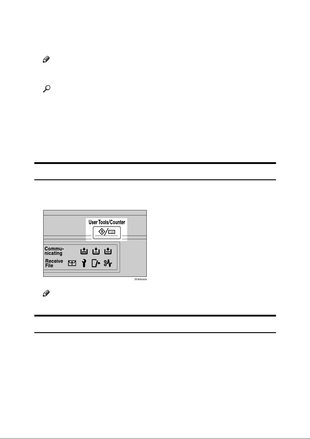
Display Panel
The display panel shows machine status, error messages, and function menus.
The function items displayed serve as selector keys. You can select or specify an
item by lightly pressing them.
When you select or specify an item on the display panel, it is highlighted like
. Keys appearing as cannot be used.
Important
❒ A force or impact of more than 30 N (about 3 kgf) will damage the display
panel.
To display the following screen, press the {User Tools/Counter} key to display the
User Tools menu, and then press [System Settings].
Using the System Settings menu screen as an example, this section explains how
to use the machine’s display panel.
1. The menu tabs for various set-
tings appear. To display the setting
you want to specify or change, press
the appropriate menu tab.
2. A list of settings appears. To spec-
ify or change a setting, press the appropriate key in the list.
3. Press this to quit the User Tools
menu.
ARM005S
2
Page 11

Accessing User Tools
This section describes how to access User Tools menu.
User Tools allow you to change or set defaults.
Note
❒ Operations for system settings differ from normal operations. Always quit
User Tools when you have finished.
❒ Any changes you make with User Tools remain in effect even if the main
power switch or operation switch is turned off, or the {Energy Saver} or {Clear
Modes} key is pressed.
❒ Default settings are shown in bold type.
Reference
p.4 “Quitting User Tools”
Changing Default Settings
This section describes how to change the settings of User Tools.
Important
❒ If Administrator Authentication Management is specified, contact your ad-
ministrator.
A Press the {User Tools/Counter} key.
B Select the menu.
To change the System Settings, press [System Settings].
To change the Copier / Document Server Features, press [Copier / Document
Server Features].
To change the Facsimile Features, press [Facsimile Features].
To change the Printer Features, press [Printer Features].
To change the Scanner Features, press [Scanner Features].
To change the language used on the display, press [Español].
To check the telephone numbers to contact for repairs, or to order consumables, press [Inquiry].
To check the counter, press [Counter].
3
Page 12
C Select the user tool you want to change.
D Change settings by following instructions on the display, and then press
[OK].
Note
❒ To cancel changes made to settings and return to the initial display, press
the {User Tools/Counter} key.
Reference
p.41 “System Settings”
p.75 “Copier / Document Server Features”
p.93 “Facsimile Features”
p.163 “Printer Features”
p.175 “Scanner Features”
p.257 “Other User Tools”
Quitting User Tools
This section describes how to end User Tools.
A Press the {User Tools/Counter} key.
Note
❒ You can also quit User Tools by pressing [Exit].
Menu Protect
Using Menu Protect, you can prevent unauthenticated users from changing the
user tools. Menu Protect can be specified for each of the following user tools
menus.
• Copier / Document Server Features
• Facsimile Features
•Printer Features
• Scanner Features
For details, consult your administrator.
4
Page 13

1. Connecting the Machine
This chapter describes how to connect the machine to the network and specify
the network settings.
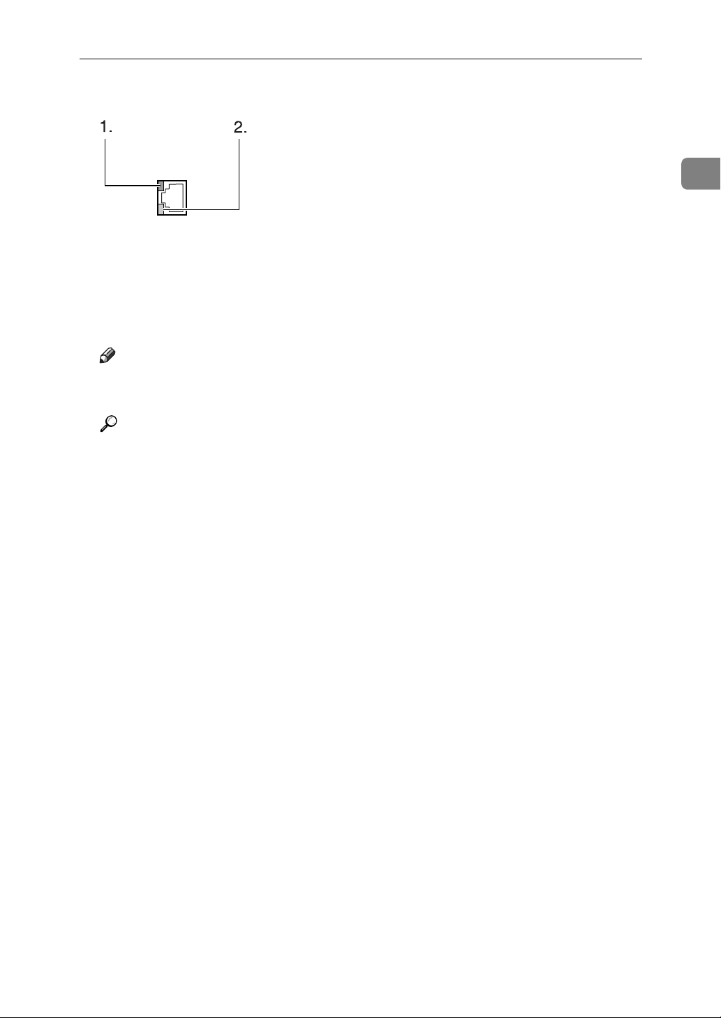
Connecting to the Interfaces
This section describes how to identify the machine’s interface and connect the
machine according to the network environment.
1. IEEE 1284 port (optional)
Port for connecting the IEEE 1284 interface cable
2. USB2.0 port
Port for connecting the USB2.0 interface
cable
3. 10BASE-T/100BASE-TX port
Port for connecting the 10BASE-T or
100BASE-TX cable
ARM001S
4. Wireless LAN port (optional)
Port for using the wireless LAN
Note
❒ You cannot install two or more of the
options below: IEEE 802.11b wireless
LAN board, IEEE 1284 Interface Board,
Bluetooth, file format converter.
5
Page 14

1
Connecting the Machine
Connecting to the Ethernet Interface
This section describes how to connect 10BASE-T or 100BASE-TX cable to the Ethernet interface.
Important
❒ If the main power switch is on, turn it off.
A A ferrite core for the Ethernet cable is supplied with this machine. Make a
loop in the cable about 9cm (3.5 inch) (1) from the machine end of the cable.
Attach the ferrite core.
AEV047S
B Make sure the main power switch of the machine is off.
C Connect the Ethernet interface cable to the 10BASE-T/100BASE-TX port.
AJO006S
D Connect the other end of the Ethernet cable to a network connection device
such as a hub.
6
Page 15
Connecting to the Interfaces
E Turn on the main power switch of the machine.
AME005S
A Indicator (green)
Lights up green when the machine is connected correctly to the network.
B Indicator (yellow)
Lights up yellow when 100 BASE-TX is in operation. Goes off when 10
BASE-T is in operation.
Note
❒ For details about installing the printer driver, see "Preparing the Machine",
Printer Reference.
Reference
"Turning On the Power", About This Machine
"Preparing the Machine", Printer Reference
1
7
Page 16
1
Connecting the Machine
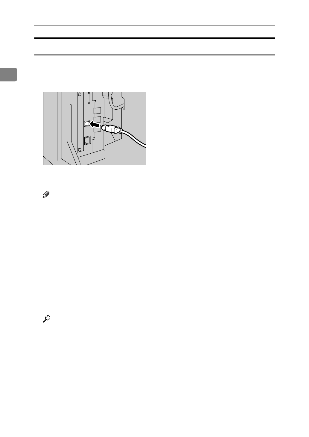
Connecting to the USB Interface
This section describes how to connect the USB2.0 interface cable to the USB2.0
port.
A Connect the USB2.0 interface cable to the USB2.0 port.
AJO003S
B Connect the other end to the USB2.0 port on the host computer.
Note
❒ This machine does not come with a USB interface cable. Make sure you
purchase the appropriate cable for the machine and your computer.
❒ The USB2.0 interface board is supported by Windows Me / 2000 / XP,
Windows Server 2003, Mac OS X 10.3.3 or higher.
• For Windows Me:
Make sure to install “USB Printing Support". When used with Windows
Me, only a speed equal to that of USB1.1 is possible.
•For Mac OS:
To use Macintosh, the machine must be equipped with the PostScript 3
option. When used with Mac OS X 10.3.3 or higher, a transfer speed of
USB2.0 is supported.
❒ For details about installing the printer driver, see "Preparing the Machine",
Printer Reference.
Reference
"Preparing the Machine", Printer Reference
8
Page 17

Connecting to the Interfaces
Connecting to the IEEE 1284 Interface
This section describes how to connect the IEEE 1284 interface cable to the IEEE
1284 interface board.
A Make sure the main power switch on the machine is off.
B Turn off the main power switch of the host computer.
C Connect the IEEE 1284 interface cable to the IEEE 1284 port.
AJO004S
1
D Connect the other end of the cable into the interface connector on the host
computer.
Check the shape of the connector to the computer. Connect the cable firmly.
E Turn on the main power switch of the machine.
F Turn on the host computer.
When using Windows 95/98/Me/2000/XP and Windows Server 2003, a
printer driver installation screen might appear when the computer is turned
on. If this happens, click [Cancel] on the screen.
Note
❒ For details about installing the printer driver, see "Preparing the Machine",
Printer Reference.
Reference
"Turning On the Power", About This Machine
"Preparing the Machine", Printer Reference
9
Page 18

1
Connecting the Machine
Connecting to the IEEE 802.11b (Wireless LAN) Interface
This section describes how to connect to the IEEE 802.11b (wireless LAN) interface.
Note
❒ Check the settings of the IP address and subnet mask of this machine.
❒ For details about how to set the IP address and subnet mask from the control
panel of the machine, see "Interface Settings".
❒ Before using this machine with an IEEE 802.11b (Wireless LAN) connection,
you must select [IEEE 802.11b] in [LAN Type].
Reference
p.49 “Network”
Setup Procedure
This section describes how to setup IEEE 802.11b (wireless LAN) interface.
Set up IEEE 802.11b (wireless LAN) according to the following procedure:
10
AME006S
Page 19

Connecting to the Interfaces
Note
❒ Select [802.11 Ad hoc] mode when connecting Windows XP as a wireless LAN
client using Windows XP standard driver or utilities, or when not using the
infrastructure mode.
❒ For details about how to specify wireless LAN settings from the control panel
on the machine, see "IEEE 802.11b".
❒ For details about how to specify wireless LAN settings from other than the
control panel on the machine, see "Using Utilities to Make Network Settings".
❒ For details about the setting items, see "IEEE 802.11b".
Reference
p.53 “IEEE 802.11b”
p.30 “Using Utilities to Make Network Settings”
Checking the Connection
This section describes how to check the wireless LAN connection.
Make sure the LED of the IEEE 802.11b interface unit is lit.
1
❖ When using in infrastructure mode
1
2
ZGDH600J
1. If [LAN Type] on the [Interface Settings] / [Network] screen is not set to [IEEE
802.11b], it does not light, even if the main power is on.
2. If it is connected properly to the network, the LED is green when in infra-
structure mode. If the LED is blinking, the machine is searching for devices.
11
Page 20

1
Connecting the Machine
❖ When using in ad hoc mode / 802.11 ad hoc mode
1
2
ZGDH600J
1. If the IEEE 802.11b interface unit is functioning, the LED lights up in or-
ange.
2. If it is connected properly to the network, the LED is green when in ad hoc
mode or 802.11 ad hoc mode. If the LED is blinking, the machine is searching
for devices. The LED will light after a few seconds.
Print the configuration page to verify settings.
Note
❒ For more information about printing a configuration page, see "Print List".
Reference
p.164 “Printing the Configuration Page”
Checking the Signal
This section describes how to check the machine's radio wave status.
When using in infrastructure mode, you can check the machine's radio wave status using the control panel.
A Press [System Settings].
B Press [Interface Settings].
C Press [IEEE 802.11b].
D Press [Wireless LAN Signal].
The machine's radio wave status appears.
E After checking radio wave status, press [Exit].
F Press the {User Tools/Counter} key to return to the User Tools / Counter / In-
quiry menu.
Reference
p.30 “Using Utilities to Make Network Settings”
p.53 “IEEE 802.11b”
12
Page 21

Network Settings
Network Settings
This section describes the network settings you can change with User Tools (System Settings). Make settings according to functions you want to use and the interface to be connected.
Important
❒ These settings should be made by the system administrator, or with the ad-
vice of the system administrator.
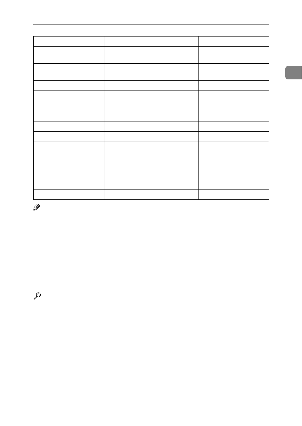
Settings Required to Use the Printer/LAN-Fax
This section lists the settings required for using the printer or LAN-Fax function.
Ethernet
This section lists the settings required for using the printer or LAN-Fax function
with an Ethernet connection.
1
For details about how to specify the settings, see "Interface Settings".
Menu User Tool Setting Requirements
Interface Settings/Network IP Address Necessary
Interface Settings/Network Gateway Address As required
Interface Settings/Network DNS Configuration As required
Interface Settings/Network DDNS Configuration As required
Interface Settings/Network Domain Name As required
Interface Settings/Network WINS Configuration As required
Interface Settings/Network NW Frame Type As required
Interface Settings/Network LAN Type Necessary
Interface Settings/Network Ethernet Speed As required
Interface Settings/Network Effective Protocol Necessary
Interface Settings/Network NCP Delivery Protocol As required
Interface Settings/Network SMB Computer Name As required
Interface Settings/Network SMB Work Group As required
Interface Settings/Network Permit SNMPv3 Communication As required
Interface Settings/Network Permit SSL/TLS Communication As required
Interface Settings/Network Host Name As required
Interface Settings/Network Machine Name As required
13
Page 22

1
Connecting the Machine
Note
❒ For the Effective Protocol setting, check that the protocol you want to use is
set to [Effective].
❒ [LAN Type] is displayed when the wireless LAN board is installed. If Ethernet
and IEEE 802.11b (wireless LAN) are both connected, the selected interface
has priority.
Reference
p.49 “Interface Settings”
IEEE 802.11b (wireless LAN)
This section lists the settings required for using the printer or LAN-Fax function
with an IEEE 802.11b (wireless LAN) connection.
For details about how to specify the settings, see "Interface Settings".
Menu User Tool Setting Requirements
Interface Settings/Network IP Address Necessary
Interface Settings/Network Gateway Address As required
Interface Settings/Network DNS Configuration As required
Interface Settings/Network DDNS Configuration As required
Interface Settings/Network Domain Name As required
Interface Settings/Network WINS Configuration As required
Interface Settings/Network NW Frame Type As required
Interface Settings/Network LAN Type Necessary
Interface Settings/Network Ethernet Speed As required
Interface Settings/Network Effective Protocol Necessary
Interface Settings/Network NCP Delivery Protocol As required
Interface Settings/Network SMB Computer Name As required
Interface Settings/Network SMB Work Group As required
Interface Settings/Network Permit SNMPv3 Communication As required
Interface Settings/Network Permit SSL/TLS Communication As required
Interface Settings/Network Host Name As required
Interface Settings/Network Machine Name As required
Interface Settings/
IEEE 802.11b
Communication Mode Necessary
14
Interface Settings/
IEEE 802.11b
Interface Settings/
IEEE 802.11b
Interface Settings/
IEEE 802.11b
SSID Setting As required
Channel As required
WEP (Encryption) Setting As required
Page 23

Network Settings
Menu User Tool Setting Requirements
Interface Settings/
IEEE 802.11b
Transmission Speed As required
Note
❒ For the Effective Protocol setting, check that the protocol you want to use is
set to [Effective].
❒ [IEEE 802.11b] and [LAN Type] are displayed when the wireless LAN interface
board is installed. If both Ethernet and wireless LAN (IEEE 802.11b) are connected, the selected interface takes precedence.
Reference
p.49 “Interface Settings”
Settings Required to Use Internet Fax
This section lists the settings required for using Internet Fax.
Ethernet
This section lists the settings required for using Internet Fax with an Ethernet
connection.
For details about how to specify the settings, see "Interface Settings" and "File
Transfer".
1
Menu User Tool Setting Requirements
Interface Settings/Network IP Address Necessary
Interface Settings/Network Gateway Address Necessary
Interface Settings/Network DNS Configuration As required
Interface Settings/Network DDNS Configuration As required
Interface Settings/Network Domain Name As required
Interface Settings/Network WINS Configuration As required
Interface Settings/Network LAN Type Necessary
Interface Settings/Network Ethernet Speed As required
Interface Settings/Network Effective Protocol Necessary
Interface Settings/Network NCP Delivery Protocol As required
Interface Settings/Network Permit SNMPv3 Communication As required
Interface Settings/Network Permit SSL/TLS Communication As required
Interface Settings/Network Host Name As required
File Transfer SMTP Server Necessary
File Transfer SMTP Authentication As required
File Transfer POP before SMTP As required
15
Page 24

Connecting the Machine
Menu User Tool Setting Requirements
File Transfer Reception Protocol Necessary
File Transfer POP3 / IMAP4 Settings As required
1
File Transfer Administrator's E-mail Address As required
File Transfer E-mail Communication Port Necessary
File Transfer E-mail Reception Interval As required
File Transfer Max. Reception E-mail Size As required
File Transfer E-mail Storage in Server As required
File Transfer Program / Change / Delete E-mail
Message
File Transfer Program / Change / Delete Subject As required
File Transfer Fax E-mail Account Necessary
As required
Note
❒ For the Effective Protocol setting, check that the protocol you want to use is
set to [Effective].
❒ [LAN Type] is displayed when the wireless LAN interface board is installed. If
both Ethernet and wireless LAN (IEEE 802.11b) are connected, the selected interface takes precedence.
❒ SMTP Server and Fax E-mail Account must be specified in order to send In-
ternet Fax.
❒ When POP before SMTP is set to [On], you must also make settings for Recep-
tion Protocol and POP3 / IMAP4 Settings.
❒ When SMTP Authentication is set to [On], you must also make settings for
Administrator's E-mail Address.
❒ E-mail Communication Port and Fax E-mail Account must be specified in or-
der to receive Internet Fax.
❒ When setting POP before SMTP to [On], check POP3 port number in E-mail
Communication Port.
16
Reference
p.49 “Interface Settings”
p.55 “File Transfer”
Page 25

Network Settings
IEEE 802.11b (wireless LAN)
This section lists the settings required for using Internet Fax with an IEEE
802.11b (wireless LAN) connection.
For details about how to specify the settings, see "Interface Settings" and "File
Transfer".
Menu User Tool Setting Requirements
Interface Settings/Network IP Address Necessary
Interface Settings/Network Gateway Address Necessary
Interface Settings/Network DNS Configuration As required
Interface Settings/Network DDNS Configuration As required
Interface Settings/Network Domain Name As required
Interface Settings/Network WINS Configuration As required
Interface Settings/Network Effective Protocol Necessary
Interface Settings/Network NCP Delivery Protocol As required
Interface Settings/Network LAN Type Necessary
1
Interface Settings/Network Permit SNMPv3 Communication As required
Interface Settings/Network Permit SSL/TLS Communication As required
Interface Settings/Network Host Name As required
Interface Settings/
IEEE 802.11b
Interface Settings/
IEEE 802.11b
Interface Settings/
IEEE 802.11b
Interface Settings/
IEEE 802.11b
Interface Settings/
IEEE 802.11b
File Transfer SMTP Server Necessary
File Transfer SMTP Authentication As required
File Transfer POP before SMTP As required
File Transfer Reception Protocol Necessary
File Transfer POP3 / IMAP4 Settings As required
File Transfer Administrator's E-mail Address As required
Communication Mode Necessary
SSID Setting As required
Channel As required
WEP (Encryption) Setting As required
Transmission Speed As required
File Transfer E-mail Communication Port Necessary
File Transfer E-mail Reception Interval As required
File Transfer Max. Reception E-mail Size As required
File Transfer E-mail Storage in Server As required
17
Page 26

Connecting the Machine
Menu User Tool Setting Requirements
1
File Transfer Program / Change / Delete E-mail
Message
File Transfer Program / Change / Delete Subject As required
File Transfer Fax E-mail Account Necessary
Note
As required
❒ For the Effective Protocol setting, check that the protocol you want to use is
set to [Effective].
❒ [IEEE 802.11b] and [LAN Type] are displayed when the wireless LAN interface
board is installed. If both Ethernet and wireless LAN (IEEE 802.11b) are connected, the selected interface takes precedence.
❒ SMTP Server and Fax E-mail Account must be specified in order to send In-
ternet Fax.
❒ When POP before SMTP is set to [On], you must also make settings for Recep-
tion Protocol and POP3 / IMAP4 Settings.
❒ When SMTP Authentication is set to [On], you must also make settings forAd-
ministrator's E-mail Address.
❒ E-mail Communication Port and Fax E-mail Account must be specified in or-
der to receive Internet Fax.
❒ When setting POP before SMTP to [On], check POP3 port number in E-mail
Communication Port.
Reference
p.49 “Interface Settings”
p.55 “File Transfer”
18
Page 27

Settings Required to Use E-mail Function
This section lists the settings required for sending e-mail.
Network Settings
Ethernet
This section lists the settings required for sending e-mail with an Ethernet connection.
For details about how to specify the settings, see "Interface Settings" and "File
Transfer".
Menu User Tool Setting Requirements
Interface Settings/Network IP Address Necessary
Interface Settings/Network Gateway Address Necessary
Interface Settings/Network DNS Configuration As required
Interface Settings/Network DDNS Configuration As required
Interface Settings/Network Domain Name As required
Interface Settings/Network WINS Configuration As required
Interface Settings/Network Effective Protocol Necessary
Interface Settings/Network Ethernet Speed As required
Interface Settings/Network LAN Type Necessary
Interface Settings/Network NCP Delivery Protocol As required
Interface Settings/Network Permit SNMPv3 Communication As required
1
Interface Settings/Network Host Name As required
File Transfer SMTP Server Necessary
File Transfer SMTP Authentication As required
File Transfer POP before SMTP As required
File Transfer Reception Protocol As required
File Transfer POP3 / IMAP4 Settings As required
File Transfer Administrator's E-mail Address As required
File Transfer E-mail Communication Port As required
File Transfer Program / Change / Delete E-mail
Message
File Transfer Program / Change / Delete Subject As required
File Transfer Scanner Recall Interval Time As required
File Transfer Number of Scanner Recalls As required
As required
19
Page 28

1
Connecting the Machine
Note
❒ For the Effective Protocol setting, check that the protocol you want to use is
set to [Effective].
❒ [LAN Type] is displayed when the wireless LAN interface board is installed. If
both Ethernet and wireless LAN (IEEE 802.11b) are connected, the selected interface takes precedence.
❒ When POP before SMTP is set to [On], you must also make settings for Recep-
tion Protocol and POP3 / IMAP4 Settings.
❒ When setting POP before SMTP to [On], check POP3 port number in E-mail
Communication Port.
Reference
p.49 “Interface Settings”
p.55 “File Transfer”
IEEE 802.11b (wireless LAN)
This section lists the settings required for sending e-mail with an IEEE 802.11b
(wireless LAN) connection.
For details about how to specify the settings, see "Interface Settings" and "File
Transfer".
Menu User Tool Setting Requirements
Interface Settings/Network IP Address Necessary
Interface Settings/Network Gateway Address Necessary
Interface Settings/Network DNS Configuration As required
Interface Settings/Network DDNS Configuration As required
Interface Settings/Network Domain Name As required
Interface Settings/Network WINS Configuration As required
Interface Settings/Network Effective Protocol Necessary
Interface Settings/Network LAN Type Necessary
Interface Settings/Network NCP Delivery Protocol As required
Interface Settings/Network Permit SNMPv3 Communication As required
Interface Settings/Network Permit SSL/TLS Communication As required
Interface Settings/Network Host Name As required
Interface Settings/
IEEE 802.11b
Interface Settings/
IEEE 802.11b
Interface Settings/
IEEE 802.11b
Communication Mode Necessary
SSID Setting As required
Channel As required
20
Page 29
Network Settings
Menu User Tool Setting Requirements
Interface Settings/
IEEE 802.11b
Interface Settings/
IEEE 802.11b
File Transfer SMTP Server Necessary
File Transfer SMTP Authentication As required
File Transfer POP before SMTP As required
File Transfer Reception Protocol As required
File Transfer POP3 / IMAP4 Settings As required
File Transfer Administrator's E-mail Address As required
File Transfer E-mail Communication Port As required
File Transfer Program / Change / Delete E-mail
File Transfer Program / Change / Delete Subject As required
File Transfer Scanner Recall Interval Time As required
File Transfer Number of Scanner Recalls As required
WEP (Encryption) Setting As required
Transmission Speed As required
As required
Message
Note
❒ For the Effective Protocol setting, check that the protocol you want to use is
set to [Effective].
❒ [LAN Type] is displayed when the wireless LAN interface board is installed. If
both Ethernet and wireless LAN (IEEE 802.11b) are connected, the selected interface takes precedence.
1
❒ When POP before SMTP is set to [On], you must also make settings for Recep-
tion Protocol and POP3 / IMAP4 Settings.
❒ When setting POP before SMTP to [On], check POP3 port number in E-mail
Communication Port.
Reference
p.49 “Interface Settings”
p.55 “File Transfer”
21
Page 30

Connecting the Machine
Settings Required to Use Scan to Folder Function
This section lists the settings required for sending files.
1
Ethernet
This section lists the settings required for sending files with an Ethernet connection.
For details about how to specify the settings, see "Interface Settings" and "File
Transfer".
Menu User Tool Setting Requirements
Interface Settings/Network IP Address Necessary
Interface Settings/Network Gateway Address Necessary
Interface Settings/Network DNS Configuration As required
Interface Settings/Network DDNS Configuration As required
Interface Settings/Network Domain Name As required
Interface Settings/Network WINS Configuration As required
Interface Settings/Network Effective Protocol Necessary
Interface Settings/Network Ethernet Speed As required
Interface Settings/Network LAN Type Necessary
Interface Settings/Network NCP Delivery Protocol As required
Interface Settings/Network Permit SNMPv3 Communication As required
Interface Settings/Network Permit SSL/TLS Communication As required
Interface Settings/Network Host Name As required
File Transfer Default User Name / Password (Send) As required
File Transfer Scanner Recall Interval Time As required
File Transfer Number of Scanner Recalls As required
Note
❒ For the Effective Protocol setting, check that the protocol you want to use is
set to [Effective].
❒ [LAN Type] is displayed when the wireless LAN interface board is installed. If
both Ethernet and wireless LAN (IEEE 802.11b) are connected, the selected interface takes precedence.
Reference
p.49 “Interface Settings”
p.55 “File Transfer”
22
Page 31

Network Settings
IEEE 802.11b (wireless LAN)
This section lists the settings required for sending files with an IEEE 802.11b
(wireless LAN) connection.
For details about how to specify the settings, see "Interface Settings" and "File Transfer".
Menu User Tool Setting Requirements
Interface Settings/Network IP Address Necessary
Interface Settings/Network Gateway Address Necessary
Interface Settings/Network DNS Configuration As required
Interface Settings/Network DDNS Configuration As required
Interface Settings/Network Domain Name As required
Interface Settings/Network WINS Configuration As required
Interface Settings/Network Effective Protocol Necessary
Interface Settings/Network LAN Type Necessary
Interface Settings/Network NCP Delivery Protocol As required
Interface Settings/Network Permit SNMPv3 Communication As required
1
Interface Settings/Network Permit SSL/TLS Communication As required
Interface Settings/Network Host Name As required
Interface Settings/
IEEE 802.11b
Interface Settings/
IEEE 802.11b
Interface Settings/
IEEE 802.11b
Interface Settings/
IEEE 802.11b
Interface Settings/
IEEE 802.11b
File Transfer Default User Name / Password (Send) As required
File Transfer Scanner Recall Interval Time As required
File Transfer Number of Scanner Recalls As required
Communication Mode Necessary
SSID Setting As required
Channel As required
WEP (Encryption) Setting As required
Transmission Speed As required
Note
❒ For the Effective Protocol setting, check that the protocol you want to use is
set to [Effective].
❒ [IEEE 802.11b] and [LAN Type] are displayed when the wireless LAN interface
board is installed. If both Ethernet and wireless LAN (IEEE 802.11b) are connected, the selected interface takes precedence.
Reference
p.49 “Interface Settings”
p.55 “File Transfer”
23
Page 32

Connecting the Machine
Settings Required to Use the Network Delivery Scanner
This section lists the settings required for delivering data to network.
1
Ethernet
This section lists the settings required for delivering data to network with an
Ethernet connection.
For details about how to specify the settings, see "Interface Settings" and "File
Transfer".
Menu User Tool Setting Requirements
Interface Settings/Network IP Address Necessary
Interface Settings/Network Gateway Address As required
Interface Settings/Network DNS Configuration As required
Interface Settings/Network DDNS Configuration As required
Interface Settings/Network Domain Name As required
Interface Settings/Network WINS Configuration As required
Interface Settings/Network Effective Protocol Necessary
Interface Settings/Network Ethernet Speed As required
Interface Settings/Network LAN Type Necessary
Interface Settings/Network NCP Delivery Protocol As required
Interface Settings/Network Permit SNMPv3 Communication As required
Interface Settings/Network Permit SSL/TLS Communication As required
Interface Settings/Network Host Name As required
File Transfer Delivery Option As required
File Transfer Fax RX File Transmission As required
File Transfer Scanner Recall Interval Time As required
File Transfer Number of Scanner Recalls As required
Note
❒ For the Effective Protocol setting, check that the protocol you want to use is
set to [Effective].
❒ [LAN Type] is displayed when the wireless LAN interface board is installed.
When both Ethernet and wireless LAN (IEEE 802.11b) are connected, the selected interface takes precedence.
❒ If Delivery Option is set to [On], check that IP Address is specified.
Reference
p.49 “Interface Settings”
p.55 “File Transfer”
24
Page 33

Network Settings
IEEE 802.11b (wireless LAN)
This section lists the settings required for delivering data to network with an
IEEE 802.11b (wireless LAN) connection.
For details about how to specify the settings, see "Interface Settings" and "File
Transfer".
Menu User Tool Setting Requirements
Interface Settings/Network IP Address Necessary
Interface Settings/Network Gateway Address As required
Interface Settings/Network DNS Configuration As required
Interface Settings/Network DDNS Configuration As required
Interface Settings/Network Domain Name As required
Interface Settings/Network WINS Configuration As required
Interface Settings/Network Effective Protocol Necessary
Interface Settings/Network LAN Type Necessary
Interface Settings/Network NCP Delivery Protocol As required
1
Interface Settings/Network Permit SNMPv3 Communication As required
Interface Settings/Network Permit SSL/TLS Communication As required
Interface Settings/Network Host Name As required
Interface Settings/
IEEE 802.11b
Interface Settings/
IEEE 802.11b
Interface Settings/
IEEE 802.11b
Interface Settings/
IEEE 802.11b
Interface Settings/
IEEE 802.11b
File Transfer Delivery Option As required
File Transfer Fax RX File Transmission As required
File Transfer Scanner Recall Interval Time As required
File Transfer Number of Scanner Recalls As required
Communication Mode Necessary
SSID Setting As required
Channel As required
WEP (Encryption) Setting As required
Transmission Speed As required
Note
❒ For the Effective Protocol setting, check that the protocol you want to use is
set to [Effective].
❒ [IEEE 802.11b] and [LAN Type] are displayed when the wireless LAN interface
board is installed. When both Ethernet and wireless LAN (IEEE 802.11b) are
connected, the selected interface takes precedence.
❒ If Delivery Option is set to [On], check that IP Address is specified.
25
Page 34

1
Connecting the Machine
Reference
p.49 “Interface Settings”
p.55 “File Transfer”
Settings Required to Use Network TWAIN Scanner
This section lists the settings required for using TWAIN Scanner under the network environment.
Ethernet
This section lists the settings required for using network TWAIN Scanner with
an Ethernet connection.
For details about how to specify the settings, see "Interface Settings".
Menu User Tool Setting Requirements
Interface Settings/Network IP Address Necessary
Interface Settings/Network Gateway Address As required
Interface Settings/Network DNS Configuration As required
Interface Settings/Network DDNS Configuration As required
Interface Settings/Network Domain Name As required
Interface Settings/Network WINS Configuration As required
Interface Settings/Network Effective Protocol Necessary
Interface Settings/Network LAN Type Necessary
Interface Settings/Network Ethernet Speed As required
Interface Settings/Network NCP Delivery Protocol As required
Interface Settings/Network Permit SNMPv3 Communication As required
Interface Settings/Network Permit SSL/TLS Communication As required
Interface Settings/Network Host Name As required
Note
❒ For the Effective Protocol setting, check that the protocol you want to use is
set to [Effective].
❒ [LAN Type] is displayed when the wireless LAN interface board is installed.
When both Ethernet and wireless LAN (IEEE 802.11b) are connected, the selected interface takes precedence.
26
Reference
p.49 “Interface Settings”
Page 35

Network Settings
IEEE 802.11b (wireless LAN)
This section lists the settings required for using network TWAIN Scanner with
an IEEE 802.11b (wireless LAN) connection.
For details about how to specify the settings, see "Interface Settings".
Menu User Tool Setting Requirements
Interface Settings/Network IP Address Necessary
Interface Settings/Network Gateway Address As required
Interface Settings/Network DNS Configuration As required
Interface Settings/Network DDNS Configuration As required
Interface Settings/Network Domain Name As required
Interface Settings/Network WINS Configuration As required
Interface Settings/Network Effective Protocol Necessary
Interface Settings/Network LAN Type Necessary
Interface Settings/Network NCP Delivery Protocol As required
Interface Settings/Network Permit SNMPv3 Communication As required
1
Interface Settings/Network Permit SSL/TLS Communication As required
Interface Settings/Network Host Name As required
Interface Settings/
IEEE 802.11b
Interface Settings/
IEEE 802.11b
Interface Settings/
IEEE 802.11b
Interface Settings/
IEEE 802.11b
Interface Settings/
IEEE 802.11b
Communication Mode Necessary
SSID Setting As required
Channel As required
WEP (Encryption) Setting As required
Transmission Speed As required
Note
❒ For the Effective Protocol setting, check that the protocol you want to use is
set to [Effective].
❒ [IEEE 802.11b] and [LAN Type] are displayed when the wireless LAN interface
board is installed. When both Ethernet and wireless LAN (IEEE 802.11b) are
connected, the selected interface takes precedence.
Reference
p.49 “Interface Settings”
27
Page 36

1
Connecting the Machine
Settings Required to Use Document Server
This section lists the settings required for using Document Server function under
the network environment.
Ethernet
This section lists the settings required for using Document Server function with
the Ethernet connection.
For details about how to specify the settings, see "Interface Settings".
Menu User Tool Setting Requirements
Interface Settings/Network IP Address Necessary
Interface Settings/Network Gateway Address As required
Interface Settings/Network DNS Configuration As required
Interface Settings/Network DDNS Configuration As required
Interface Settings/Network Domain Name As required
Interface Settings/Network WINS Configuration As required
Interface Settings/Network Effective Protocol Necessary
Interface Settings/Network Ethernet Speed As required
Interface Settings/Network LAN Type Necessary
Interface Settings/Network NCP Delivery Protocol As required
Interface Settings/Network Permit SNMPv3 Communication As required
Interface Settings/Network Permit SSL/TLS Communication As required
Interface Settings/Network Host Name As required
Note
❒ For the Effective Protocol setting, check that the protocol you want to use is
set to [Effective].
❒ [LAN Type] is displayed when the wireless LAN interface board is installed.
When both Ethernet and wireless LAN (IEEE 802.11b) are connected, the selected interface takes precedence.
Reference
p.49 “Interface Settings”
28
Page 37

Network Settings
IEEE 802.11b (wireless LAN)
This section lists the settings required for using Document Server function with
an IEEE 802.11b (wireless LAN) connection.
For details about how to specify the settings, see "Interface Settings".
Menu User Tool Setting Requirements
Interface Settings/Network IP Address Necessary
Interface Settings/Network Gateway Address As required
Interface Settings/Network DNS Configuration As required
Interface Settings/Network DDNS Configuration As required
Interface Settings/Network Domain Name As required
Interface Settings/Network WINS Configuration As required
Interface Settings/Network Effective Protocol Necessary
Interface Settings/Network LAN Type Necessary
Interface Settings/Network NCP Delivery Protocol As required
Interface Settings/Network Permit SNMPv3 Communication As required
1
Interface Settings/Network Permit SSL/TLS Communication As required
Interface Settings/Network Host Name As required
Interface Settings/
IEEE 802.11b
Interface Settings/
IEEE 802.11b
Interface Settings/
IEEE 802.11b
Interface Settings/
IEEE 802.11b
Interface Settings/
IEEE 802.11b
Communication Mode Necessary
SSID Setting As required
Channel As required
WEP (Encryption) Setting As required
Transmission Speed As required
Note
❒ For the Effective Protocol setting, check that the protocol you want to use is
set to [Effective].
❒ [IEEE 802.11b] and [LAN Type] are displayed when the wireless LAN interface
board is installed. When both Ethernet and wireless LAN (IEEE 802.11b) are
connected, the selected interface takes precedence.
Reference
p.49 “Interface Settings”
29
Page 38

1
Connecting the Machine
Using Utilities to Make Network Settings
This section describes how to make network settings using utilities.
You can also specify network settings using utilities such as Web Image Monitor,
SmartDeviceMonitor for Admin, and telnet.
Note
❒ For details about using Web Image Monitor, see "Using Web Image Monitor",
Network Guide.
❒ For details about using SmartDeviceMonitor for Admin, see "Using SmartDe-
viceMonitor for Admin", Network Guide.
❒ For Details about using telnet, see "Remote Maintenance", Network Guide.
Reference
"Using Web Image Monitor", Network Guide
"Using SmartDeviceMonitor for Admin", Network Guide
"Remote Maintenance by telnet", Network Guide
Interface Settings
This section describes how to make Interface settings using utilities.
Change settings by using Web Image Monitor, SmartDeviceMonitor for Admin,
and telnet.
❖ [Network] → [IP Address] → [Auto-Obtain (DHCP)]
• Web Image Monitor: Can be used for specifying the setting.
• SmartDeviceMonitor for Admin: Can be used for specifying the setting.
• telnet: Can be used for specifying the setting.
❖ [Network] → [IP Address] → [Specify] → [IP Address]
• Web Image Monitor: Can be used for specifying the setting.
• SmartDeviceMonitor for Admin: Can be used for specifying the setting.
• telnet: Can be used for specifying the setting.
❖ [Network] → [IP Address] → [Specify] → [Sub-net Mask]
• Web Image Monitor: Can be used for specifying the setting.
• SmartDeviceMonitor for Admin: Can be used for specifying the setting.
• telnet: Can be used for specifying the setting.
❖ [Network] → [Gateway Address]
• Web Image Monitor: Can be used for specifying the setting.
• SmartDeviceMonitor for Admin: Can be used for specifying the setting.
• telnet: Can be used for specifying the setting.
30
Page 39

Network Settings
❖ [Network] → [DNS Configuration] → [Auto-Obtain (DHCP)]
• Web Image Monitor: Can be used for specifying the setting.
• SmartDeviceMonitor for Admin: Cannot be used for specifying the setting.
• telnet: Can be used for specifying the setting.
❖ [Network] → [DNS Configuration] → [Specify] → "DNS Server 1-3"
• Web Image Monitor: Can be used for specifying the setting.
• SmartDeviceMonitor for Admin: Cannot be used for specifying the setting.
• telnet: Can be used for specifying the setting.
❖ [Network] → [DDNS Configuration]
• Web Image Monitor: Can be used for specifying the setting.
• SmartDeviceMonitor for Admin: Cannot be used for specifying the setting.
• telnet: Can be used for specifying the setting.
❖ [Network] → [Domain Name] → [Auto-Obtain (DHCP)]
• Web Image Monitor: Can be used for specifying the setting.
• SmartDeviceMonitor for Admin: Cannot be used for specifying the setting.
• telnet: Can be used for specifying the setting.
1
❖ [Network] → [Domain Name] → [Specify] → [Domain Name]
• Web Image Monitor: Can be used for specifying the setting.
• SmartDeviceMonitor for Admin: Cannot be used for specifying the setting.
• telnet: Can be used for specifying the setting.
❖ [Network] → [WINS Configuration] → [On] → "Primary WINS Server"
• Web Image Monitor: Can be used for specifying the setting.
• SmartDeviceMonitor for Admin: Cannot be used for specifying the setting.
• telnet: Can be used for specifying the setting.
❖ [Network] → [WINS Configuration] → [On] → "Secondary WINS Server"
• Web Image Monitor: Can be used for specifying the setting.
• SmartDeviceMonitor for Admin: Cannot be used for specifying the setting.
• telnet: Can be used for specifying the setting.
❖ [Network] → [WINS Configuration] → [On] → "Scope ID"
• Web Image Monitor: Can be used for specifying the setting.
• SmartDeviceMonitor for Admin: Cannot be used for specifying the setting.
• telnet: Can be used for specifying the setting.
31
Page 40

1
Connecting the Machine
❖ [Network] → [WINS Configuration] → [Off]
• Web Image Monitor: Can be used for specifying the setting.
• SmartDeviceMonitor for Admin: Cannot be used for specifying the setting.
• telnet: Can be used for specifying the setting.
❖ [Network] → [Effective Protocol] → "TCP / IP"
• Web Image Monitor: Cannot be used for specifying the setting.
• SmartDeviceMonitor for Admin: You can specify the TCP/IP settings if
SmartDeviceMonitor for Admin is communicating with the machine using
IPX/SPX.
• telnet: Can be used for specifying the setting.
❖ [Network] → [Effective Protocol] → "NetWare"
• Web Image Monitor: Can be used for specifying the setting.
• SmartDeviceMonitor for Admin: You can specify the IPX/SPX settings if
SmartDeviceMonitor for Admin is communicating with the machine using
TCP/IP.
• telnet: Can be used for specifying the setting.
❖ [Network] → [Effective Protocol] → "SMB"
• Web Image Monitor: Can be used for specifying the setting.
• SmartDeviceMonitor for Admin: Can be used for specifying the setting.
• telnet: Can be used for specifying the setting.
❖ [Network] → [Effective Protocol] → "AppleTalk"
• Web Image Monitor: Can be used for specifying the setting.
• SmartDeviceMonitor for Admin: Can be used for specifying the setting.
• telnet: Can be used for specifying the setting.
❖ [Network] → [NCP Delivery Protocol]
• Web Image Monitor: Can be used for specifying the setting.
• SmartDeviceMonitor for Admin: Can be used for specifying the setting.
• telnet: Cannot be used for specifying the setting.
❖ [Network] → [NW Frame Type] → [Auto Select]
• Web Image Monitor: Can be used for specifying the setting.
• SmartDeviceMonitor for Admin: Cannot be used for specifying the setting.
• telnet: Can be used for specifying the setting.
❖ [Network] → [NW Frame Type] → [Ethernet II]
• Web Image Monitor: Can be used for specifying the setting.
• SmartDeviceMonitor for Admin: Cannot be used for specifying the setting.
• telnet: Can be used for specifying the setting.
32
Page 41

Network Settings
❖ [Network] → [NW Frame Type] → [Ethernet 802.2]
• Web Image Monitor: Can be used for specifying the setting.
• SmartDeviceMonitor for Admin: Cannot be used for specifying the setting.
• telnet: Can be used for specifying the setting.
❖ [Network] → [NW Frame Type] → [Ethernet 802.3]
• Web Image Monitor: Can be used for specifying the setting.
• SmartDeviceMonitor for Admin: Cannot be used for specifying the setting.
• telnet: Can be used for specifying the setting.
❖ [Network] → [NW Frame Type] → [Ethernet SNAP]
• Web Image Monitor: Can be used for specifying the setting.
• SmartDeviceMonitor for Admin: Cannot be used for specifying the setting.
• telnet: Can be used for specifying the setting.
❖ [Network] → [SMB Computer Name]
• Web Image Monitor: Can be used for specifying the setting.
• SmartDeviceMonitor for Admin: Cannot be used for specifying the setting.
• telnet: Can be used for specifying the setting.
1
❖ [Network] → [SMB Work Group]
• Web Image Monitor: Can be used for specifying the setting.
• SmartDeviceMonitor for Admin: Cannot be used for specifying the setting.
• telnet: Can be used for specifying the setting.
❖ [Network] → [Ethernet Speed]
• Web Image Monitor: Cannot be used for specifying the setting.
• SmartDeviceMonitor for Admin: Cannot be used for specifying the setting.
• telnet: Cannot be used for specifying the setting.
❖ [Network] → [LAN Type] → [Ethernet]
• Web Image Monitor: Can be used for specifying the setting.
• SmartDeviceMonitor for Admin: Cannot be used for specifying the setting.
• telnet: Can be used for specifying the setting.
❖ [Network] → [LAN Type] → [IEEE 802.11b]
• Web Image Monitor: Can be used for specifying the setting.
• SmartDeviceMonitor for Admin: Cannot be used for specifying the setting.
• telnet: Can be used for specifying the setting.
33
Page 42

1
Connecting the Machine
❖ [Network] → [Ping Command]
• Web Image Monitor: Cannot be used for specifying the setting.
• SmartDeviceMonitor for Admin: Cannot be used for specifying the setting.
• telnet: Cannot be used for specifying the setting.
❖ [Network] → [Permit SNMP V3 Communication] → [Encryption Only]
• Web Image Monitor: Can be used for specifying the setting.
• SmartDeviceMonitor for Admin: Cannot be used for specifying the setting.
• telnet: Can be used for specifying the setting.
❖ [Network] → [Permit SNMP V3 Communication] → [Encryption / Clear Text]
• Web Image Monitor: Can be used for specifying the setting.
• SmartDeviceMonitor for Admin: Cannot be used for specifying the setting.
• telnet: Can be used for specifying the setting.
❖ [Network] → [Permit SSL / TLS Communication] → [Ciphertext Only]
• Web Image Monitor: Cannot be used for specifying the setting.
• SmartDeviceMonitor for Admin: Cannot be used for specifying the setting.
• telnet: Cannot be used for specifying the setting.
❖ [Network] → [Permit SSL / TLS Communication] → [Ciphertext Priority]
• Web Image Monitor: Cannot be used for specifying the setting.
• SmartDeviceMonitor for Admin: Cannot be used for specifying the setting.
• telnet: Cannot be used for specifying the setting.
❖ [Network] → [Permit SSL / TLS Communication] → [Ciphertext / Clear Text]
• Web Image Monitor: Cannot be used for specifying the setting.
• SmartDeviceMonitor for Admin: Cannot be used for specifying the setting.
• telnet: Cannot be used for specifying the setting.
❖ [Network] → [Host Name]
• Web Image Monitor: Can be used for specifying the setting.
• SmartDeviceMonitor for Admin: Can be used for specifying the setting.
• telnet: Can be used for specifying the setting.
❖ [Network] → [Machine Name]
• Web Image Monitor: Can be used for specifying the setting.
• SmartDeviceMonitor for Admin: Cannot be used for specifying the setting.
• telnet: Can be used for specifying the setting.
34
Page 43

Network Settings
❖ [IEEE 802.11b] → [Communication Mode]
• Web Image Monitor: Can be used for specifying the setting.
• SmartDeviceMonitor for Admin: Cannot be used for specifying the setting.
• telnet: Can be used for specifying the setting.
❖ [IEEE 802.11b] → [SSID Setting]
• Web Image Monitor: Can be used for specifying the setting.
• SmartDeviceMonitor for Admin: Cannot be used for specifying the setting.
• telnet: Can be used for specifying the setting.
❖ [IEEE 802.11b] → [Channel]
• Web Image Monitor: Can be used for specifying the setting.
• SmartDeviceMonitor for Admin: Cannot be used for specifying the setting.
• telnet: Can be used for specifying the setting.
❖ [IEEE 802.11b] → [WEP (Encryption) Setting]
• Web Image Monitor: Can be used for specifying the setting.
• SmartDeviceMonitor for Admin: Cannot be used for specifying the setting.
• telnet: Can be used for specifying the setting.
1
❖ [IEEE 802.11b] → [Transmission Speed]
• Web Image Monitor: Cannot be used for specifying the setting.
• SmartDeviceMonitor for Admin: Cannot be used for specifying the setting.
• telnet: Can be used for specifying the setting.
❖ [File Transfer] → [SMTP Server]
• Web Image Monitor: Can be used for specifying the setting.
• SmartDeviceMonitor for Admin: Cannot be used for specifying the setting.
• telnet: Cannot be used for specifying the setting.
❖ [File Transfer] → [SMTP Authentication]
• Web Image Monitor: Can be used for specifying the setting.
• SmartDeviceMonitor for Admin: Cannot be used for specifying the setting.
• telnet: Cannot be used for specifying the setting.
❖ [File Transfer] → [POP before SMTP]
• Web Image Monitor: Can be used for specifying the setting.
• SmartDeviceMonitor for Admin: Cannot be used for specifying the setting.
• telnet: Cannot be used for specifying the setting.
35
Page 44

1
Connecting the Machine
❖ [File Transfer] → [Reception Protocol]
• Web Image Monitor: Can be used for specifying the setting.
• SmartDeviceMonitor for Admin: Cannot be used for specifying the setting.
• telnet: Cannot be used for specifying the setting.
❖ [File Transfer] → [POP3 / IMAP4 Settings]
• Web Image Monitor: Can be used for specifying the setting.
• SmartDeviceMonitor for Admin: Cannot be used for specifying the setting.
• telnet: Cannot be used for specifying the setting.
❖ [File Transfer] → [Administrator's E-mail Address]
• Web Image Monitor: Can be used for specifying the setting.
• SmartDeviceMonitor for Admin: Cannot be used for specifying the setting.
• telnet: Cannot be used for specifying the setting.
❖ [File Transfer] → [E-mail Communication Port]
• Web Image Monitor: Can be used for specifying the setting.
• SmartDeviceMonitor for Admin: Cannot be used for specifying the setting.
• telnet: Cannot be used for specifying the setting.
❖ [File Transfer] → [E-mail Reception Interval]
• Web Image Monitor: Can be used for specifying the setting.
• SmartDeviceMonitor for Admin: Cannot be used for specifying the setting.
• telnet: Cannot be used for specifying the setting.
❖ [File Transfer] → [Max. Reception E-mail Size]
• Web Image Monitor: Can be used for specifying the setting.
• SmartDeviceMonitor for Admin: Cannot be used for specifying the setting.
• telnet: Cannot be used for specifying the setting.
❖ [File Transfer] → [E-mail Storage in Server]
• Web Image Monitor: Can be used for specifying the setting.
• SmartDeviceMonitor for Admin: Cannot be used for specifying the setting.
• telnet: Cannot be used for specifying the setting.
❖ [File Transfer] → [Default User Name / Password (Send)]
• Web Image Monitor: Can be used for specifying the setting.
• SmartDeviceMonitor for Admin: Cannot be used for specifying the setting.
• telnet: Cannot be used for specifying the setting.
36
Page 45

Network Settings
❖ [File Transfer] → [Fax E-mail Account]
• Web Image Monitor: Cannot be used for specifying the setting.
• SmartDeviceMonitor for Admin: Cannot be used for specifying the setting.
• telnet: Cannot be used for specifying the setting.
❖ [File Transfer] → [Scanner Recall Interval Time]
• Web Image Monitor: Cannot be used for specifying the setting.
• SmartDeviceMonitor for Admin: Cannot be used for specifying the setting.
• telnet: Cannot be used for specifying the setting.
❖ [File Transfer] → [Number of Scanner Recalls]
• Web Image Monitor: Cannot be used for specifying the setting.
• SmartDeviceMonitor for Admin: Cannot be used for specifying the setting.
• telnet: Cannot be used for specifying the setting.
1
37
Page 46

Connecting the Machine
R
Connecting the Machine to a Telephone Line and Telephone
1
This section describes how to connect the machine to the telephone lines and select the line type.
Connecting the Telephone Line
This section describes how to connect the machine to the telephone lines.
To connect the machine to a telephone line, use a snap-in modular type connector.
CAUTION:
• To reduce the risk of fire, use only No. 26 AWG or larger telecommunication line cord.
RATTENTION:
• Pour réduire le risque d'incendie, utiliser uniquement des conducteurs de télécommunications 26 AWG ou de section supérieure.
Important
❒ By law in the United States, you must program your phone number identifi-
cation (your fax number) into your machine before you can connect the public
phone system. See "Registering Fax Information".
❒ Make sure the connector is the correct type before you start.
ARM003S
1. External telephone connector
2. G3 (analog) line interface connector
3. Extra G3 line interface connector
Reference
p.112 “Registering Fax Information”
38
Page 47

Connecting the Machine to a Telephone Line and Telephone
Selecting the Line Type
This section describes how to select the line type.
Select the line type to which the machine is connected. There are two types: tone
and pulse dial.
Select the line type using Administrator Tools.
Note
❒ This function is not available in some regions.
Reference
p.110 “Select Dial / Push Phone”
Connecting the Optional Handset or an External Telephone
You can connect the optional handset or an external telephone to the machine.
You can use it for telephone calls.
Limitation
❒ When you use the optional handset or an external telephone with the {On
Hook Dial} key for telephone calls, you can not talk with the other party with-
out pressing the {On Hook Dial} key after taking off the receiver.
1
❖ Specifying the handset line type
ND1X00E0
The switch on the handset should be in the appropriate position-TT (Tone Dialing) or DP (Pulse Dialing).
39
Page 48

1
Connecting the Machine
❖ Adjusting the handset bell volume
ND1X00E1
Adjust the handset ringer volume using the volume switch.
Note
❒ Some external telephones may not be connected or may suffer reduced func-
tionality.
40
Page 49

2. System Settings
This chapter describes user tools in the System Settings menu. For details on
how to access System Settings, see "Accessing User tools (System Settings)".
General Features
This section describes the user tools in the General Features menu under System
Settings.
Default settings are shown in bold type.
❖ Panel Tone
The beeper (key tone) sounds when a key is pressed.
The default setting is On.
❖ Warm Up Notice (copier/Document Server)
You can have the beeper sound when the machine becomes ready to copy after leaving Energy Saver mode, or when the power is turned on.
The default setting is On.
❖ Copy Count Display (copier/Document Server)
The copy counter can be set to show the number of copies made (count up) or
the number of copies yet to be made (count down).
The default setting is Up (count up).
❖ Function Priority
Specify the mode to be displayed immediately after the operation switch is
turned on, or when System Reset mode is turned on.
The default setting is Copier.
❖ Print Priority
Print Priority is given to the mode selected.
When [Interleave] is selected, the current print job will be interrupted after a
maximum of five sheets.
The default setting is Display Mode.
When [Interleave] is selected, the current print job will be interrupted after a
maximum of five sheets.
When the Internal Tray 2 (1 bin tray), Shift Sort Tray, 500–sheet finisher, or
1000–sheet finisher is installed on the machine, you can specify an output tray
for each documents are delivered. For details about how to specify an output
tray for each function, see "Output: coier", "Output: Document Server", "Output: Facsimile", "Output: Printer".
41
Page 50

2
System Settings
❖ Function Reset Timer
You can set the length of time the machine waits before changing modes
when using the multi-access function.
This is useful if you are making many copies and have to change settings for
each copy. If you set a longer reset period, you can prevent interruption from
other functions.
The Function Reset Timer setting is ignored if [Interleave] is set for Print Priority.
The default setting is Set Time.
When you select [Set Time], enter the time (3–30 seconds, in 1 second increments) using the number keys.
The default setting for Set Time is 3 seconds.
❖ Output: Copier (copier)
Specify a tray to which documents are delivered.
1. Internal Tray 1
2. Internal Tray 2
3. Finisher Upper Tray
4. Finisher Shift Tray
The default setting is Internal Tray 1.
❖ Output: Document Server (Document Server)
Specify a tray to which documents are delivered.
The default setting is Internal Tray 1.
❖ Output: Facsimile (facsimile)
Specify a tray to which documents are delivered.
The default setting is Internal Tray 1.
❖ Output: Printer (printer)
Specify a tray to which documents are delivered.
The default setting is Internal Tray 1.
The output trays set on the printer driver have priority over the output tray
specified above.
42
AHR009S
Page 51

Reference
p.3 “Accessing User Tools”
"Function Compatibility", Copy/Document Server Reference
Output tray settings
General Features
Important
❒ You cannot interrupt the current job with a different function job that speci-
fies stapling or sorting.
❒ You can interrupt the current job with an ordinary copy job or facsimile re-
ception. The output tray used when the job is interrupted varies depending
on the type of finisher shift tray and output tray specified for interruption.
❖ When 500–sheet finisher is the finisher shift tray:
• When the output tray specified for the interrupting job is the finisher tray,
the interrupting job will be delivered to internal tray 1.
• When the output tray specified for the interrupting job is not the finisher
tray, the interrupting job will be delivered to the specified output tray.
❖ When 1000–sheet finisher is the finisher shift tray:
• When the output tray specified for the interrupting job is the finisher tray,
the interrupting job will be delivered to the finisher upper tray.
• When the output tray specified for the interrupting job is not the finisher
tray, the interrupting job will be delivered to the specified output tray.
When the 500–sheet finisher or 1000–sheet finisher is installed and stapling is
specified for a job, the job will be delivered to the finisher shift tray, regardless
of the output tray specified.
2
43
Page 52

2
System Settings
Tray Paper Settings
This section describes the user tools in the Tray Paper Settings menu under System Settings.
Default settings are shown in bold type.
Important
❒ If the specified paper size differs from the actual size of the paper loaded in
the paper tray, a misfeed might occur because the correct paper size was not
detected.
❖ Paper Tray Priority: Copier (copier/Document Server)
Specify the tray to supply paper for output.
The default setting is Tray 1.
❖ Paper Tray Priority: Facsimile (facsimile)
Specify the tray to supply paper for output.
The default setting is Tray 1.
❖ Paper Tray Priority: Printer (printer)
Specify the tray to supply paper for output.
The default setting is Tray 1.
❖ Tray Paper Size: Tray 1-4
Select the size of the paper loaded in the paper tray.
• The paper sizes you can set for tray 1, 3 and 4 are as follows:
A3L, B4 JISL, A4K, A4L, B5 JISK, B5 JISL, A5L, 8KL, 16KK, 16KL
1
11"×17"L, 8
1
7
/4"×101/2"L, 8"×13"L, 81/2"×13"L, 81/4"×13"L, 11"×14"L, 81/4"×14"L,
1
8"×10
/2"L, 8"×101/2"K, custom size (140-297 mm (5.52"-11.69")
/2"×14"L, 81/2"×11"K, 81/2"×11"L, 51/2"×81/2"L,
wide x 182-432 mm (7.17"-17.00") long)
• The paper sizes you can set for tray 2 are as follows:
A3L, B4 JISL, A4K, A4L, B5 JISK, B5 JISL, A5L, B6 JISL, A6L,
PostcardL, 8KL, 16KK, 16KL
11"×17"L, 8
1
/4"×101/2"L, 71/4"×101/2"K, 8"×13"L, 81/2"×13"L, 81/4"×13"L,
7
11"×14"L, 11"×15"L, 10"×14"L, 10"×15"L, 8
1
8"×10
3
/2"K, 8"×10"L, 8"×10"K, C5 EnvL, C6 EnvL, DL EnvL,
7
/8"×71/2"L, 41/8"×91/2"L, custom size (100-297 mm (3.97"-11.69")
1
/2"×14"L, 81/2"×11"K, 81/2"×11"L, 51/2"×81/2"L,
1
/4"×14"L, 8"×101/2"L,
wide x 148-432 mm (5.83"-17.00") long)
The default setting for Tray 1 is A4K / 8
1
" × 11"K.
2
The default setting for Tray 2 is A3L / 11" × 17"L.
The default setting for Tray 3 is B5 JISK / 8
The default setting for Tray 4 is B4 JISL / 8
1
/2" × 11"L.
1
/2" × 14"L.
44
Page 53

Tray Paper Settings
The paper guide for the optional LCT is fixed for A4K, 81/2"×11"K size paper. Contact your service representative if you need to change the paper size.
If the paper size set for the selector in paper tray is different to the paper size
for this setting, the paper size of the dial has priority.
If you load paper of a size not indicated on the paper size selector in the paper
tray, set the dial to " ".
❖ Paper Type: Bypass Tray
Sets the display so you can see what type of paper is loaded in the bypass tray.
• The paper types you can set for the bypass tray are as follows:
No Display, Recycled Paper, Special Paper, Color Paper, Letterhead, Preprinted Paper, Prepunched Paper, Label Paper, Bond Paper, Thick Paper,
OHP, Thin Paper, Cardstock
The default setting is No Display.
❖ Paper Type: Tray 1-4
Sets the display so you can see what type of paper is loaded in each paper
tray. The print function uses this information to automatically select the paper tray.
• The paper types you can set for trays 1, 3 and 4 are as follows:
No Display, Recycled Paper, Special Paper, Color Paper, Letterhead, Preprinted Paper, Prepunched Paper, Bond Paper, Cardstock
2
• The paper types you can set for tray 2 are as follows:
No Display, Recycled Paper, Special Paper, Color Paper, Letterhead, Preprinted Paper, Prepunched Paper, Label Paper, Bond Paper, Thick Paper,
OHP, Thin Paper, Cardstock
The default setting for "Paper Type" is No Display.
The default setting for "Copying Method in Duplex" is 2 Sided Copy.
The default setting for "Apply Auto Paper Select" is Yes.
When paper of the same type and size is loaded in two different paper trays
and you want to specify tray for 2 Sided Copy and tray for 1 Sided Copy,
specify the upper tray for 2 Sided Copy. If one of the trays is specified as the
default in Paper Tray Priority, assign 2 Sided Copy to that tray.
A mark appears next to the paper tray if [No] is selected in "Auto Paper Select".
"Auto Paper Select" can only be selected for the copier function if [No Display]
and [Recycled Paper] are selected. If [No] is selected, Auto Paper Select is not
valid for the tray.
❖ Cover Sheet Tray
Allows you to specify and display the paper tray that is setting cover sheets.
After selecting the paper tray, you can also specify the display timing and
copy method for two-sided copying.
The default setting for "Tray to Program" is Off.
Functions using the cover sheet tray setting are the front cover function and
front/back cover function.
When [At Mode Selected] is selected, cover sheet tray settings only appear
when the cover function or slip sheet function is selected.
When [Full Time] is selected, the cover sheet tray is always displayed.
You can set Copying Method in Duplex only when [At Mode Selected] is selected.
45
Page 54

System Settings
❖ Slip Sheet Tray
Allows you to specify and display the paper tray that is inserting slip sheets.
After selecting the paper tray, you can also specify the display timing and
copy method for two-sided copying.
The default setting for "Tray to Program" is Off.
When [At Mode Selected] is selected, slip sheet tray settings only appear when
the cover function or slip sheet function is selected.
2
❖ Printer Bypass Paper Size
Specify the size of the paper in the bypass tray when printing data from the
computer.
• The paper sizes you can set for bypass tray are as follows:
A3L, B4 JISL, A4K, A4L, B5 JISK, B5 JISL, A5K, A5L, A6L,
11" × 17"L, 8
1
7
/4" × 101/2"K, 71/4" × 101/2"L, 8" × 13"L, 81/2" × 13"L, 81/4" × 13"L, 8KL,
16KK, 16KL, 4
1
/2" × 14"L, 81/2" × 11"K, 81/2" × 11"L, 51/2" × 81/2"L,
1
/8" × 91/2"L, 37/8" × 71/2"L, C5 EnvL, C6 EnvL,
DL EnvL
The default setting is 8
1
/2" × 11"K.
You can specify a custom size of between 90.0 and 297.0 mm (3.6"-11.7") vertically, and between 148.0 and 600.0 mm (5.9"-23.6") horizontally.
Reference
p.3 “Accessing User Tools”
"Covers", Copy/ Document Server Reference
"Slip Sheets", Copy/ Document Server Reference
46
Page 55

Timer Settings
Timer Settings
This section describes the user tools in the Timer Settings menu under System
Settings.
Default settings are shown in bold type.
❖ Auto Off Timer
After a specified period has passed, following job completion, the machine
automatically turns off, in order to conserve energy. This function is called
"Auto Off". The machine status after the Auto Off operation is referred to as
"Off mode", or "Sleep mode". For the Auto Off Timer, specify the time to
elapse before "Auto Off".
The default setting is 1 minute(s).
Enter a time interval between 10 seconds and 240 minutes, using the number
keys
From "Off mode" or "Sleep mode", the machine is ready to use within 10 seconds.
Auto Off may not work when error messages appear.
The machine may not shift to "Sleep Mode" at the set time, if the main power
switch has just been turned on and functions other than copier function are
still in the process of starting up.
2
❖ Panel Off Timer
Set the amount of time the machine waits before switching the panel off after
copying has finished or the last operation is performed.
Enter a time interval between 10 seconds and 240 minutes, using the number
keys.
The default setting is 1 minute(s).
❖ System Auto Reset Timer
The System Reset setting automatically switches the screen to that of the function set in Function Priority when no operations are in progress, or when an
interrupted job is cleared. This setting determines the system reset interval.
The time can be set from 10 to 999 seconds, using the number keys
The default setting is On, 60 seconds.
❖ Copier / Document Server Auto Reset Timer (copier/Document Server)
Specifies the time to elapse before copier and Document Server modes reset.
If [Off] is selected, the machine does not automatically switch to the user code
entry screen.
The time can be set from 10 to 999 seconds, using the number keys.
The default setting is On, 60 seconds.
❖ Facsimile Auto Reset Timer (facsimile)
Specifies the time to elapse before the facsimile mode resets.
The time can be set from 30 to 999 seconds, using the number keys.
The default setting is 30 seconds.
47
Page 56

2
System Settings
❖ Printer Auto Reset Timer (printer)
Specifies the time to elapse before the printer function resets.
If [Off] is selected, the machine does not automatically switch to the user code
entry screen.
The time can be set from 10 to 999 seconds, using the number keys.
The default setting is On, 60 seconds.
❖ Scanner Auto Reset Timer (scanner)
Specifies the time to elapse before the scanner function resets.
If [Off] is selected, the machine will not automatically switch to the user code
entry screen.
The time can be set from 10 to 999 seconds, using the number keys.
The default setting time is On, 60 seconds.
❖ Set Date
Set the date for the copier's internal clock using the number keys.
To change between year, month, and day, press [ ← ] and [ → ].
❖ Set Time
Set the time for the copier's internal clock using the number keys.
Enter the time using the 24–hour format (in 1 second increments).
To change between hours, minutes and seconds, press [ ← ] and [ → ].
❖ Auto Logout Timer
Specify whether or not to automatically log out a user when the user does not
operate the machine for a specified period of time after logging in.
The time can be set from 60 to 999 seconds, in one second increments, using
the number keys.
The default setting time is Off.
Reference
p.3 “Accessing User Tools”
48
Page 57

Interface Settings
Interface Settings
This section describes the user tools in the Interface Settings menu under System
Settings.
Default settings are shown in bold type.
Network
This section describes the user tools in the Network menu under Interface Settings.
❖ IP Address
Before using this machine in the network environment, you must specify the
IP address and subnet mask.
When you select [Specify], enter the IP Address and subnet mask as
"xxx.xxx.xxx.xxx" ("x" indicates a number).
The default setting is Auto-Obtain (DHCP).
When you select [Specify], make sure that the IP address is different from that
of other machines on the network.
The physical address (MAC address) also appears.
❖ Gateway Address
A gateway is a connection or interchange point between two networks.
Specify the gateway address for the router or host computer used as a gateway.
The default setting is 000.000.000.000.
❖ DNS Configuration
Make settings for the DNS server.
When you select [Specify] , enter the DNS Server IP address as
“xxx.xxx.xxx.xxx"(“x" indicates a number).
The default setting is Auto-Obtain (DHCP).
2
❖ DDNS Configuration
Specify the DDNS settings.
The default setting is Active.
❖ Domain Name
Specify the domain name.
Enter the domain name using up to 63 characters.
❖ WINS Configuration
Specify the WINS server settings.
The default setting is Off.
If [On] is selected, enter the WINS Server IP address as “xxx.xxx.xxx.xxx"(“x"
indicates a number).
If DHCP is in use, specify the scope ID.
Enter the scope ID using up to 31 characters.
49
Page 58

2
System Settings
❖ Effective Protocol
Select the protocol to use in the network.
The default setting for TCP/IP is Effective.
The default setting for NetWare is Effective.
The default setting for SMB is Effective.
The default setting for AppleTalk is Effective.
❖ NCP Delivery Protocol
Select the protocol for NCP delivery.
The default setting is TCP / IP Priority.
❖ NW Frame Type
Select the frame type when you use NetWare.
The default setting is Auto Select.
❖ SMB Computer Name
Specify the SMB computer name.
Enter the computer name using up to 15 characters.
"*+,/:;<>=?[\]|. and spaces cannot be entered.
Do not set a computer name starting with RNP and rnp.
Use uppercase letters for alphabets.
❖ SMB Work Group
Specify the SMB work group.
Enter the computer name using up to 15 characters.
"*+,/:;<>=?[\]|. and spaces cannot be entered.
Use uppercase letters for alphabet.
❖ Ethernet Speed
Set the access speed for networks.
The default setting is Auto Select.
Select a speed that matches your network environment. [Auto Select] should
usually be selected.
❖ LAN Type
When you have installed the IEEE 802.11b interface unit, select the method of
connection.
The default setting is Ethernet.
[LAN Type] is displayed when wireless LAN board is installed. If Ethernet and
IEEE 802.11b (wireless LAN) are both connected, the selected interface has
priority.
50
Page 59

Interface Settings
❖ Ping Command
Check the network connection with ping command using given IP address.
If you fail to connect to the network, check the following, and then retry the
ping command.
• Make sure that “TCP/IP” in [Effective Protocol] is set to “Effective”.
• Check that the machine with assigned IP address is connected to the network.
• There is a possibility that the same IP address is used for the specified
equipment.
❖ Permit SNMP V3 Communication
Set the encrypted communication of SNMPv3.
The default setting is Encryption / Clear Text.
If you select to [Encryption Only], you need to set an encryption password for
the machine.
❖ Permit SSL / TLS Communication
Set the encrypted communication of SSL / TLS.
The default setting is Ciphertext Priority.
If you set to [Ciphertext Only], you need to install the SSL certificate for the machine.
2
❖ Host Name
Specify the host name.
Enter the host name using up to 63 characters.
❖ Machine Name
Specify the machine name.
Enter the machine name using up to 31 characters.
51
Page 60

System Settings
Parallel Interface
This section describes the user tools in the Parallel Interface menu under Interface Settings.
[Parallel Interface] is displayed when this machine is installed with the IEEE 1284
interface board.
2
❖ Parallel Timing
Specify the timing for the parallel interface. Normally, you do not need to
change this setting.
The default setting is ACK Outside.
❖ Parallel Communication Speed
Sets the communication speed for the parallel interface. If the speed is too
high, data may not be transferred smoothly. If this happens, change the setting to "Standard".
The default setting is High Speed.
❖ Selection Signal Status
Sets the level for the select signal of the parallel interface.
The default setting is High.
❖ Input Prime
Sets whether to validate or invalidate the input prime signal upon reception.
Normally you do not need to change this setting.
The default setting is Invalid.
❖ Bidirectional Communication
Sets the printer's response mode to a status acquisition request when using a
parallel interface. If you experience problems using another manufacturer's
machine, set this to "Off".
The default setting is On.
When set to [Off], the bidirectional communication function will be disabled,
and the printer driver will not be installed under Windows Auto Detect function.
❖ Signal Control
Specifies how error during printing or sending facsimile from the computer
is to be dealt with. Normally, you do not need to change this setting.
The default setting is Job Acceptance Priority.
52
Page 61

Interface Settings
IEEE 802.11b
This section describes the user tools in the IEEE 802.11b menu under Interface
Settings.
[IEEE 802.11b] is displayed when this machine is installed with the wireless LAN
interface board.
Be sure to make all settings simultaneously.
❖ Communication Mode
Specifies the communication mode of the wireless LAN.
The default setting is 802.11 Ad hoc.
❖ SSID Setting
Specifies SSID to distinguish the access point in infrastructure mode or 802.11
ad hoc mode.
The characters that can be used are ASCII 0x20-0x7e (32 bytes).
If blank is specified in 802.11b ad hoc mode or ad hoc mode, “ASSID" appears.
Default setting is blank (ASSID).
❖ Channel
Specifies a channel when you select 802.11b ad hoc mode or ad hoc mode.
The default setting is 11.
The following channels are available:
•Metric version: 1-14
• Inch version: 1-11
❖ WEP (Encryption) Setting
Specifies the encryption of the IEEE 802.11b (wireless LAN). If this is set to
[Active], you must enter the WEP key.
•WEP
The default setting is Inactive.
•Encryption
10 alphanumeric characters must be entered for 64 bit, 26 characters for 128 bit.
2
❖ Wireless LAN Signal
When using in infrastructure mode, you can check the machine's radio wave
status using the control panel.
Radio wave status is displayed when you press [Wireless LAN Signal].
❖ Transmission Speed
Specifies the communication speed of the IEEE 802.11b (wireless LAN).
The default setting is Auto.
❖ Return to Defaults
You can return the IEEE 802.11b (wireless LAN) settings to their defaults.
Reference
p.3 “Accessing User Tools”
53
Page 62

System Settings
Print List
This section describes how to print the configuration page.
You can check items related to the network environment.
The configuration page shows the current network settings and network information.
2
A Press [System Settings].
B Press [Interface Settings].
C Press [Print List].
D Press the {Start} key.
The configuration page is printed.
E Press [Exit].
F Press the {User Tools/Counter} key.
Note
❒ You can also exit by pressing [Exit] on the User Tools main menu.
54
Page 63

File Transfer
File Transfer
This section describes the user tools in the File Transfer menu under System Settings.
Default settings are shown in bold type.
❖ Delivery Option
Enables or disables sending stored or scanned documents to the ScanRouter
delivery server.
The default setting is Off.
Specify this option when selecting whether or not to use the ScanRouter delivery software. If you do, you will have to preregister I/O devices in the
ScanRouter delivery software.
❖ Capture Server IP Address
Specify the capture server IP address.
This setting appears when the media link board is installed, and that the capture function is being used by the ScanRouter delivery software.
❖ Fax RX File Transmission
2
• Setting per Line
Specifies whether or not received fax documents are sent to the ScanRouter
delivery software for each fax line.
The default setting for Line 1 is Do not Deliver.
The default setting for Line 2 is Do not Deliver.
The default setting for Line 3 is Do not Deliver.
•Print at Deliver
Specifies whether or not received fax documents sent to ScanRouter delivery software should also be printed at the same time.
The default setting is Do not Print.
• File to Deliver
Specifies whether all received fax documents or only received fax documents that include delivery codes (documents with an ID and SUB/SEP
code) are sent to ScanRouter delivery software.
The default setting is All Files.
• Dlvry Failure File
•Print File
• Delete File
If a received fax document cannot be sent to ScanRouter delivery software,
it is stored in memory. To print a stored file, select [Print File] to delete, select [Delete File].
If the machine can send the data to ScanRouter delivery software, it does
so automatically.
If you delete the data, you will not be able to distribute or print it.
55
Page 64

2
System Settings
❖ SMTP Server
Specify the SMTP server name.
If DNS is in use, enter the host name.
If DNS is not in use, enter the SMTP server IP address.
The default setting for "Port No." is 25.
Enter the server name using up to 127 characters. Spaces cannot be entered.
Enter port number between 1 and 65535 using the number keys, and then
press the {q} key.
SMTP server shares the same port number with Direct SMTP server.
❖ SMTP Authentication
Specify SMTP authentication (PLAIN, LOGIN, CRAMMD5, DIGEST-MD5).
When sending e-mail to an SMTP server, you can enhance the SMTP server
security level using authentication that requires entering the user name and
password.
If the SMTP server requires authentication, set [SMTP Authentication] to [On],
and then specify the user name, password and encryption.
Enter the user name using up to 191 characters. Spaces cannot be entered. Depending on the SMTP server type, "realm" must be specified. Add "@" after
the user name, as in "user name@realm".
Enter the password using up to 63 characters. Spaces cannot be entered.
• Select Encryption as follows:
"Encryption"-[Auto]: Use If the authentication method is PLAIN, LOGIN,
CRAM-MD5, or DIGEST-MD5.
"Encryption"-[On]: Use If the authentication method is CRAMMD5 or DIGEST-MD5.
"Encryption"-[Off]: Use If the authentication method is PLAIN, or LOGIN.
Enter the user name and password to be set for the Administrator's e-mail address when using Internet Fax.
The default setting is Off.
56
Page 65

File Transfer
❖ POP before SMTP
Specify POP authentication (POP before SMTP).
When sending e-mail to an SMTP server, you can enhance the SMTP server
security level by connecting to the POP server for authentication.
If you set POP before SMTP to [On], specify the waiting time after authentication, user name, e-mail address and password.
• Wait Time after Authent.: 300 msec
Specify "Wait Time after Authent." from zero to 10,000 milliseconds, in increments of one millisecond.
•User Name
Enter the user name using up to 63 characters. Spaces cannot be entered.
• E-mail Address
• Password
Enter the password using up to 63 characters. Spaces cannot be entered.
The default setting is Off.
To enable POP server authentication before sending e-mail via the SMTP
server, set [POP before SMTP] to [On]. E-mail is sent to the SMTP server after the
time specified for "Wait Time after Authent." has elapsed.
If you select [On], enter server name in POP3 / IMAP4 Settings. Also, check
POP3 port number in E-mail Communication Port.
2
❖ Reception Protocol
Specify Reception Protocol for receiving Internet Fax.
The default setting is POP3.
❖ POP3 / IMAP4 Settings
Specify the POP3/IMAP4 server name for receiving Internet faxes.
The specified POP3/IMAP4 server name is used for [POP before SMTP].
•Server Name
If DNS is in use, enter the host name.
If DNS is not in use, enter the POP3/IMAP4 or server IP address.
Enter POP3/IMAP4 server name using up to 127 characters. Spaces cannot
be entered.
•Encryption
•Auto
Password encryption is automatically set according to the POP/IMAP
server settings.
•On
Encrypt password.
•Off
Do not encrypt password.
57
Page 66

2
System Settings
❖ Administrator's E-mail Address
On e-mailed scanned documents, if the sender is not specified this appears as
the sender's address.
When sending e-mail under the Internet fax function, administrator's e-mail
address will appear as the sender’s address under the following conditions:
• The sender has not been specified and the machine’s e-mail address has
not been registered.
• The specified sender is not registered in the machine’s address book and
the machine’s e-mail address has not been registered.
When conducting SMTP authentication for the transmitted files under the Internet fax function, the Administrator's E-mail Address will appear in the
“From:" box. If you have specified the user name and e-mail address in [SMTP
Authentication], make sure to specify this setting.
Enter up to 128 characters.
On e-mailed scanned documents, if [Auto Specify Sender Name] is [Off], specify
the sender.
❖ E-mail Communication Port
Specify the port numbers for receiving Internet faxes. The specified POP3
port number is used for POP before SMTP.
The default setting for POP3 is 110.
The default setting for IMAP4 is 143.
The default setting for SMTP is 25.
Enter a port number between 1 and 65535 using the number keys, and then
press the {q} key.
❖ E-mail Reception Interval
Specify, in minutes, the time interval for receiving Internet faxes via POP3 or
IMAP4 server.
The default setting is On, 15 minute(s)
If [On] is selected, the time can be set from 2 to 1440 minutes in increments of
one minute.
❖ Max. Reception E-mail Size
Specify the maximum reception e-mail size for receiving Internet faxes.
The default setting is 2MB.
Enter a size from one to 50 MB in increments of one megabyte.
❖ E-mail Storage in Server
Specify whether or not to store received Internet fax e-mails on the POP3 or
IMAP4 server.
The default setting is Off.
❖ Default User Name / Password (Send)
Specify the user name and password required when sending scan files directly to a shared folder on a computer running Windows, to an FTP server, or to
a NetWare server.
Enter in up to 64 characters.
58
Page 67

File Transfer
❖ Program / Change / Delete E-mail Message
You can program, change, or delete the e-mail message used when sending
an Internet fax or scan file as an attachment.
Program / Change:
A Press [System Settings].
B Press [File Transfer].
C Press [TNext].
D Press [Program / Change / Delete E-mail Message].
E Press [*Not Programmed].
To change the registered e-mail message, select the e-mail message to
change.
F Press [Change].
G Enter a name, and then press [OK].
Enter the name using up to 20 characters.
H Press [Edit].
To start a new line, press [OK] to return to the e-mail message screen, and
then press [TNext] in "Select Line to Edit:".
I Enter the text, and then press [OK].
Enter up to five lines of text. Each line can consist of up to 80 characters.
2
J Press [OK].
K Press [Exit].
Delete:
A Press [System Settings].
B Press [File Transfer].
C Press [TNext].
D Press [Program / Change / Delete E-mail Message].
E Press [Delete].
F Select the e-mail message to delete.
The confirmation message about deleting appears.
G Press [Yes].
H Press [Exit].
59
Page 68

2
System Settings
❖ Program / Change / Delete Subject
You can program, change, or delete the subject used when sending an Internet fax or scan file as an attachment.
Program / Change:
A Press [System Settings].
B Press [File Transfer].
C Press [TNext].
D Press [Program / Change / Delete Subject].
E Press [*Not Programmed].
To change the registered subject, select the subject to change.
F Enter the text, and then press [OK].
Enter the subject using up to 20 characters.
G Press [Exit].
Delete:
A Press [System Settings].
B Press [File Transfer].
C Press [TNext].
D Press [Program / Change / Delete Subject].
E Press [Delete].
F Select the subject to delete.
The confirmation message about deleting appears.
G Press [Yes].
H Press [Exit].
❖ Scanner Recall Interval Time
Specifies the interval the machine waits before resending a scan file, if it cannot be sent to the delivery server or mail server.
The default setting is 300 seconds.
The interval time can be set from 60 to 999 seconds in one second increments,
using the number keys.
This setting is for the scanner function.
❖ Number of Scanner Recalls
Sets a maximum number of times a scan file is resent to the delivery server or
mail server.
The default setting is On, 3 time(s).
If [On] is selected, the number of times can be set from 1 to 99. This setting is
for the scanner function.
This setting is for the scanner function.
60
Page 69

File Transfer
❖ Fax E-mail Account
Specify e-mail address, user name and password for receiving Internet faxes.
• E-mail Address
Enter an e-mail address using up to 128 characters.
•User Name
Enter a user name using up to 64 characters.
• Password
Enter a password using up to 64 characters.
❖ Auto Specify Sender Name
Set whether or not to specify the name of the sender when sending e-mail.
•On
If you select [On], the specified e-mail address will appear in the “From:"
box. If you do not specify the sender’s address, the administrator’s e-mail
address will appear in the “From:" box.
If you do not specify the sender when sending a file by e-mail under the
fax function, or if the specified e-mail address is not registered in the machine’s address book, the machine’s e-mail address will appear in the
“From:” box. If the machine does not have an e-mail address, the administrator’s e-mail address will appear in the “From:” box.
2
•Off
If you select [Off], the specified e-mail address will appear in the “From:"
box, but you cannot send e-mail without specifying the sender’s e-mail address. Under the fax function, you cannot send e-mail if the specified sender’s e-mail address is not registered in the machine’s address book.
The default setting is Off.
Reference
p.3 “Accessing User Tools”
61
Page 70

2
System Settings
Administrator Tools
This section describes the user tools in the Administrator Tools menu under System Settings.
Default settings are shown in bold type.
Administrator Tools are used by the administrator. To change these settings,
contact the administrator.
We recommend specifying Administrator Authentication before making Administrator Tools settings.
❖ User Authentication Management
•User Code Auth.
Using User Code Authentication, you can limit the available functions and
supervise their use.
When using User Code Authentication, register the user code.
Using the Printer PC Control function, you can obtain a log of prints corresponding to the codes entered using the printer driver.
For details about Basic Authentication, Windows Authentication, LDAP
Authentication, and Integration Server Authentication, consult your administrator.
•Copier
•Document Server
•Facsimile
•Scanner
•Printer
• Printer: PC Control
•Basic Auth.
•Windows Auth.
•LDAP Auth.
• Integration Svr. Auth.
•Off
The default setting is Off.
❖ Administrator Authentication Management
For details about this function, consult your administrator.
❖ Program / Change Administrator
For details about this function, consult your administrator.
❖ Key Counter Management
Specify the functions you want to manage with the key counter.
62
Page 71

Administrator Tools
❖ Extended Security
Specify whether or not to use the extended security functions. For details
about the extended security functions, consult your administrator.
❖ Display / Print Counter
Allows you to view and print the number of prints.
• Display / Print Counter
Displays the number of prints for each function (Total, Copier, Facsimile,
Printer, A3 / DLT, Duplex, Staple).
•Print Counter List
Prints out a list of the number of prints made under each function.
❖ Display / Clear / Print Counter per User
Allows you to view and print the numbers of prints accessed with user codes,
and to set those values to 0.
Press [UPrevious] and [TNext] to show all the numbers of prints.
The number of prints may differ from the counter values shown in Display /
Print Counter.
• Print Counter List for All Users
Prints the counter value for all the users.
2
• Clear Counter List for All Users
Resets the counter value for all the users.
• Print Counter List per User
Prints the counter value for each user.
•Clear Counter List per User
Resets the counter value for each user.
63
Page 72

2
System Settings
❖ Address Book Management
You can add, change or delete information registered in the Address Book.
For details, see “Address Book”.
• Program / Change
You can register and change names as well as user codes.
•Names
You can register a name, key display, registration number, and title selection.
•Auth. Info
You can register a user code, and specify the functions available to each
user code. You can also register user names and passwords to be used
when sending e-mail, sending files to folders, or accessing an LDAP
server.
•Protection
You can register a protection code.
•Fax Dest.
You can register a fax number, international TX mode, fax header, label
insertion, IP-Fax destination, and protocol.
•E-mail
You can register an e-mail address.
•Folder
You can register the protocol, path, port number, and server name.
• Add to Group
You can put names registered in the Address Book into a group.
• Delete
You can delete a name from the Address Book.
You can register up to 2,000 names.
You can register up to 100 user codes. If you add the optional user account
enhance unit, you can register up to 500 user codes.
You can also register and manage names in the Address Book using Web Image Monitor or SmartDeviceMonitor for Admin.
❖ Address Book: Program / Change / Delete Group
Names registered in the Address Book can be added into a group.
You can then easily manage the names registered in each group.
• Program / Change
You can register new groups, or changes a group name, key display, title
selection or registration number.
• Delete
You can delete a group from the Address Book.
You can register up to 100 groups.
You can also register and manage groups in the Address Book using Web Image Monitor or SmartDeviceMonitor for Admin.
64
Page 73

Administrator Tools
❖ Address Book: Program / Change / Delete Transfer Request
You can register fax destinations for the Transfer Request function in facsimile mode.
For details about operations, see “Registering the Transfer Request”.
• Program / Change
This registers new transfer requests and receiving stations, or changes the
transfer request name, key name, title selection, registration number, fax
destination, IP-Fax destination, or e-mail address.
• Delete
Deletes a Transfer request.
You can register up 10 transfer requests.
❖ Address Book: Change Order
Changes the order of registered names.
You can rearrange the order of items on the same page, but you cannot move
items to another page.
For example, you cannot move an item from “PLANNING” ([OPQ]) to “DAILY” ([CD]).
A Press [System Settings].
B Press [Administrator Tools].
2
C Press [TNext].
D Press [Address Book: Change Order].
E Press the name key to be moved.
You can select a name using the number keys.
65
Page 74

2
System Settings
F Press the name key in the place you want to move it to.
The user key is moved to the selected position, and the user key currently
at the selected position is moved forward or backward.
If you move the selected user key forward, the user key currently at the selected position is moved backward.
If you move the selected user key backward, the user key currently at the
selected position is moved forward.
You can also select a name using the number keys.
❖ Print Address Book: Destination List
You can print the destination list registered in the Address Book.
•Print in Title 1 Order
Prints the Address Book in Title 1 order.
•Print in Title 2 Order
Prints the Address Book in Title 2 order.
•Print in Title 3 Order
Prints the Address Book in Title 3 order.
•Print Group Dial List
Prints the group Address Book.
A Press [System Settings].
B Press [Administrator Tools].
C Press [TNext].
D Press [Print Address Book: Destination List].
E Select the print format.
F To print the list on two-sided pages, select [Print on 2 Sides].
G Press the {Start} key.
The list prints out.
66
Page 75

❖ Address Book: Edit Title
You can edit the title to easily find a user.
A Press [System Settings].
B Press [Administrator Tools].
C Press [TNext].
D Press [Address Book: Edit Title].
Administrator Tools
E Press the title key you want to change.
F Enter the new name, and then press [OK].
G Press [OK].
❖ Address Book: Select Title
Specifies the title to select a name.
The default setting is Title 1.
❖ Auto Delete File in Document Server
Specify whether documents stored in the Document Server will or will not be
deleted after a specified period of time.
The default setting is Yes, After 3 day(s).
If you select [Yes], documents stored subsequently are deleted after the specified period.
If you select [No], documents are not automatically deleted.
If you select [Yes], enter a number of days from 1 to 180 (in 1 day increments).
The default is 3 days, this means documents are deleted 3 days (72 hours) after they are stored.
2
❖ Delete All Files in Document Server
You can delete files stored in the Document Server, including files stored for
Sample Print, Locked Print, Hold Print, and Stored Print under the printer
function.
Even if a password is always set, all documents are deleted.
A confirmation message appears. To delete all documents, select [Yes].
67
Page 76

2
System Settings
❖ Program / Change / Delete LDAP Server
Program the LDAP server to find up e-mail destinations in the LDAP server
Address Book directly. This function is possible when sending scan files by email using the scanner or fax function.
To start an LDAP search, make sure that the items listed below are set. For
other items, check your environment and make any necessary changes.
•Server Name
•Search Base
•Port No.
• Search Conditions
• Authentication method selection
To use the LDAP server in Administrator Tools, select [On] under LDAP server.
This function supports LDAP Version 2.0 and 3.0. Ver 2.0 does not support
High Security authentication.
❖ Use LDAP Server
Specify whether or not to use the LDAP server for searching.
The default setting is Off.
When Use LDAP Server is set to Off, [Search LDAP] will not appear on the
searching display.
❖ AOF (Always On)
Specify whether or not to use Auto Off.
The default setting is On.
❖ Firmware Version
You can check the version of the software installed in this machine.
❖ Network Security Level
For details about this function, consult your administrator.
❖ Reduce Recovery Time
You can specify whether or not to shorten the recovery time.
The default setting is Off.
If you press [On], the recovery time is shortened.
If you press [Off], the recovery time is lengthened and the machine's power
consumption is reduced.
This setting appears only if the copier unit and hard disk are installed in the
machine.
❖ Delete All Logs
For details about this function, consult your administrator.
❖ Transfer Log Setting
For details about this function, consult your administrator.
❖ Unauthorized Copy Control
For details about this function, consult your administrator.
68
Page 77

Reference
p.3 “Accessing User Tools”
p.183 “Address Book”
p.197 “Printing the Counter for Each User”
p.246 “Registering the Transfer Request”
p.259 “Counter”
Program / Change / Delete LDAP Server
This section describes how to specify the LDAP server settings.
To program / change the LDAP server
This section describes how to program / change the LDAP server.
A Press [System Settings].
B Press [Administrator Tools].
Administrator Tools
2
C Press [Program / Change / Delete LDAP Server].
D Check that [Program / Change] is selected.
E Select the LDAP server you want to program or change.
When programming the server, select [*Not Programmed].
F Set each item as necessary.
G Press [OK] after setting each item.
For details about LDAP server, see "Programming the LDAP server".
H Press [Exit].
I Press the {User Tools/Counter} key.
Reference
p.70 “Programming the LDAP server”
69
Page 78

System Settings
To delete the programmed LDAP server
This section describes how to delete the programmed LDAP server.
A Press [System Settings].
B Press [Administrator Tools].
2
C Press [Program / Change / Delete LDAP Server].
D Press [Delete].
E Select the LDAP server you want to delete.
F Press [Yes].
G Press [Exit].
H Press the {User Tools/Counter} key.
Programming the LDAP server
This section describes how to specify the LDAP server settings.
To enter an identification name
This section describes how to enter a identification name.
A Press [Change] under “Name”.
Register a name for the LDAP server that will appear on the server selection
screen of the LDAP search operation.
B Enter the server’s identification name.
C Press [OK].
To enter a server name
This section describes how to enter a server name.
A Press [Change] under “Server Name”.
Register the LDAP server’s host name or IP address.
B Enter the LDAP server name.
C Press [OK].
70
Page 79

Administrator Tools
To enter the search base
This section describes how to enter the search base.
A Press [Change] under “Search Base”.
Select a route folder to start the search from e-mail addresses registered in the
selected folder are search targets.
B Enter the search base.
For example, if the search target is the sales department of ABC company, enter “dc=sales department, o=ABC”. (In this example, the description is for an
active directory. “dc” is for the organization unit, and “o” is for the company.)
Search base registration may be required depending on your server environment. When registration is required, unspecified searches will result in error.
Check your server environment and enter any required specifications.
C Press [OK].
To enter a port number
This section describes how to enter a port number.
A Press [Change] under “Port No.”.
Specify the port number for communicating with the LDAP server. Specify a
port that is compliant with your environment.
B Enter the port number using the number keys, and then press the {q} key.
When SSL is set to [On], the port number automatically changes to “636”.
2
To start SSL communication
This section describes how to specify SSL communication.
A Press [On] under "Use Secure Connection (SSL).
Use SSL to communicate with the LDAP server.
To use SSL, the LDAP server must support SSL.
When SSL is set to [On], the port number automatically changes to “636”.
SSL setting must be enabled on this machine. For details, consult your network administrator.
71
Page 80

2
System Settings
To set authentication
This section describes how to specify authentication.
A Press [TNext].
B Press [On] or [High Security] under “Authentication”.
To make a search request to the LDAP server, use the administrator account
for authentication.
Authentication settings must comply with your server’s authentication settings. Check your server settings before setting this machine.
[High Security] is available only with LDAP Version 3.0.
When [High Security] is selected, the administrator password is encrypted before it is sent to the network. When [On] is selected, the password is sent without encryption.
To enter the user name and password
This section describes how to enter the user name and password.
A Press [TNext].
B Press [Change] under “User Name”.
When [On] or [High Security] is selected for the authentication setting, use the
administrator account name and password. Do not enter the administrator
account name and password when using authentication for each individual
or each search.
C Enter the user name, and then press [OK].
Procedures for the user name setting differ depending on server environment. Check your server environment before making the setting.
Example: Domain Name\User Name, User Name@Domain Name,
CN=Name, OU=Department Name, DC=Server Name
D Press [Change] under “Password”.
E Enter the password, and then press [OK].
The user name and password are required for administrator authentication to
access the LDAP server.
You can set the user name and password in this machine’s Address Book to
allow individual authentication access to the LDAP server. Use Administra-
72
tor Tools to select the user name and password you want to use.
Page 81

Administrator Tools
To test the connection
This section describes how to test the connection.
A Press [Connection Test].
Access the LDAP server to check the proper connection is established. Check
authentication works according to the authentication settings.
A connection test is carried out.
B Press [Exit].
If the connection test fails, check your settings and try again.
This function does not check search conditions or the search base.
To set search conditions
This section describes how to specify search conditions.
A Press [TNext] twice.
B Press [Change] for items you want to use as search conditions from the fol-
lowing: [Name], [E-mail Address], [Fax Number], [Company Name], and [Depart-
ment Name].
You can enter an attribute as a typical search keyword. Using the entered attribute, the function searches the LDAP server’s Address Book.
C Enter the attribute you want to use when searching for e-mail addresses,
and then press [OK].
The attribute value may change depending on the server environment. Check
the attribute value complies with your server environment before setting it.
You can leave items blank, but you cannot leave attributes blank when
searching for e-mail addresses from the LDAP server Address Book.
2
73
Page 82

System Settings
To set search options
This section describes how to specify search options.
A Press [TNext] three times.
B Press [Change] under "Attribute".
2
C Enter the attribute you want to use when searching for e-mail addresses,
and then press [OK].
To search the LDAP server data using a keyword other than prepared keywords such as Name, E-mail Address, FAX Number, Company Name, and
Department Name, specify the attribute for the keyword registered in your
LDAP server, and the name to be displayed on the control panel during the
search. For example, to search e-mail addresses by employee number, enter
“employeeNo.” in the Attribute field, and “Employee No.” in the key display
field.
The attribute value may change depending on the server environment. Check
the attribute complies with your server environment before setting it.
D Press [Change] under "Key Display".
E Enter the key display, and then press [OK].
The registered “key display” appears as a keyword for searching LDAP.
• Without key display registration
74
• With key display registration
The key does not appear on the search screen unless both “Attribute” and
“Key Display” are registered. Make sure you register both to use the optional
search.
Page 83

3. Copier / Document Server
Features
This chapter describes user tools in the Copier / Document Server Features menu.
For details on how to access Copier / Document Server Features, see "Accessing
User Tools (System Settings)".
General Features
This section describes the user tools in the General Features menu under Copier /
Document Server Features.
Default settings are shown in bold type.
❖ Auto Paper Select Priority
Auto Paper Select is the default setting. You can cancel this setting.
The default setting is On.
❖ Auto Tray Switching
If you load paper of the same size in two or more trays, the machine automatically shifts to the other when the first tray runs out of paper (when Auto Paper Select is selected.) This function is called “Auto Tray Switching”. This
setting specifies whether to use Auto Tray Switching or not.
• With Image Rotation
Use to copy when using the Auto Tray Switching function.
• Without Image Rotation
Only copies with Auto Tray Switching if you load paper of the same size
and in the same orientation in two or more trays. If the paper is not the
same size or in the same orientation, copying is interrupted and the message “Load paper.” is displayed.
•Off
When a paper tray runs out of paper, copying is interrupted and the message “Load paper.” is displayed.
The default setting is With Image Rotation.
❖ Paper Display
You can choose to have the available paper trays and sizes shown on the initial display.
The default setting is Display.
If you select [Hide], the display is shown as below. Press [Auto Paper Select] to
display paper sizes.
75
Page 84

3
Copier / Document Server Features
❖ Original Type Priority
You can select the original type effective when the power is turned on, or
modes cleared.
The default setting is Text.
❖ Original Type Display
You can have the original types shown on the initial display.
The default setting is Display.
If you select [Hide], the display is as below.
❖ Auto Image Density Priority
You can set whether Auto Image Density is "On" or "Off" when the machine
is turned on, reset, or modes are cleared.
The default setting for "Text" is On.
The default setting for "Text/Photo" is On.
The default setting for "Photo" is Off.
The default setting for "Pale" is On.
The default setting for "Generation Copy" is On.
❖ Copy Quality
You can adjust the quality level of copies for each original type (Text,
Text/Photo, Photo, Pale, Generation Copy).
•Text
Adjust text sharpness.
The default setting is Normal.
"Custom Setting" is the value set during service setup.
Choosing "Sharp" or "Sort" affects the outline sharpness of text.
•Text/Photo
When there are photo(s) and text on the original, select which takes priority.
The default setting is Normal.
"Custom Setting" is the value set during service setup.
"Normal" gives a balanced text and photo reproduction.
•Photo
For a photo original, adjust the finish quality level to match the type of
photo original.
The default setting is Print Photo.
"Custom Setting" is the value set during service setup.
Select "Print Photo" for printed photo originals, and "Coarse Print" for a
coarse dot finish, such as newspaper photos.
Select "Glossy Photo" for printed photo and text originals.
76
Page 85

General Features
•Pale
Adjust the quality level for the finish of a pale original with normal density.
The default setting is Normal.
"Custom Setting" is the value set during service setup.
• Generation Copy
Adjust the quality level so as not to thicken the lines of the finish image.
The default setting is Normal.
"Custom Setting" is the value set during service setup.
❖ Image Density
You can select one of seven original image density levels for each original
type (Text, Text/Photo, Photo, Pale, Generation Copy).
The default setting for "Text" is Normal.
The default setting for "Text/Photo" is Normal.
The default setting for "Photo" is Normal.
The default setting for "Pale" is Normal.
The default setting for "Generation Copy" is Normal.
❖ Duplex Mode Priority
You can select the type of the Duplex function effective when the power is
turned on, or modes cleared.
The default setting is 1 Sided→1 Sided (Metric version) / 1 Sided→2 Sided
(Inch version)
3
❖ Copy Orientation in Duplex Mode
You can set the copy orientation when making two-sided copies.
The default setting is Top to Top.
❖ Original Orientation in Duplex Mode
You can set the original orientation when making two-sided copies.
The default setting is Top to Top.
❖ Change Initial Mode
You can select standard mode or Program No.10 as the mode effective when
power is turned on, or modes cleared.
The default setting is Standard.
❖ Max. Copy Quantity
The maximum copy quantity can be set between 1 and 999.
The default setting is 99 sheet(s).
❖ Tone: Original Remains
The beeper (key tone) sounds if you forget to remove originals after copying.
The default setting is On.
If Panel Tone of User Tools (System Settings) is [Off] the beeper does not
sound irrespective of the Tone: Original Remains setting.
77
Page 86

3
Copier / Document Server Features
❖ Job End Call
You can choose whether or not the beeper sounds when copying is complete.
The default setting is On.
If Panel Tone of User Tools (System Settings) settings is [On], the machine
beeps to notify you that it did not complete a job for reasons such as copying
was interrupted, the paper tray ran out of paper, or a paper jam occurred.
❖ Copy Function Key: F1-F5
You can assign frequently used functions to function keys F1 to F5.
The default setting for "Copy Function Key: F1" is 1 Sided→2 Sided: T to T.
The default setting for "Copy Function Key: F2" is 2 Sided: T to T→2 Sided: T to T.
The default setting for "Copy Function Key: F3" is 1 Sided→1 Sided Combine.
The default setting for "Copy Function Key: F4" is 1 Sided→1 Sided Com-
bine: 4 originals.
The default setting for "Copy Function Key: F5" is Create Margin.
❖ Document Server Storage Key: F1-F5
You can assign frequently used functions to function keys F1 to F5. You can
also change assigned functions.
The default setting for "Document Server Storage Key: F1" is 2 Sided Original
Top to Top.
The default setting for "Document Server Storage Key: F2" is 1 Sided→1 Sided
Combine.
The default setting for "Document Server Storage Key: F3" is 1 Sided→1 Sided
Combine: 4 originals.
The default setting for "Document Server Storage Key: F4" is 1 Sided→1 Sided
Combine: 8 originals.
The default setting for "Document Server Storage Key: F5" is Create Margin.
Reference
p.3 “Accessing User Tools”
p.41 “Warm Up Notice (copier/Document Server)”
"Selecting the Original Type Setting", Copy/ Document Server Reference
"Adjusting Copy Image Density", Copy/ Document Server Reference
78
"Selecting Copy Paper", Copy/ Document Server Reference
Page 87

Reproduction Ratio
Reproduction Ratio
This section describes the user tools in the Reproduction Ratio menu under
Copier / Document Server Features.
Default settings are shown in bold type.
❖ Shortcut R / E
You can register up to three frequently used Reduce/Enlarge ratios other
than the fixed Reduce/Enlarge ratio and have them shown on the initial display. You can also change registered Reduce/Enlarge ratios.
If no Reduce/Enlarge ratio has been set when selecting [Shortcut R / E 1], [Short-
cut R / E 2], or [Shortcut R / E 3], enter the ratio using the number keys.
❖ Enlarge 1-5
You can customize available enlargement ratios by pressing [Reduce / Enlarge],
followed by [Enlarge].
3
The default setting for "Enlarge 1" is 115% (Metric version) / 121% (Inch version).
The default setting for "Enlarge 2" is 122% (Metric version) / 129% (Inch version).
The default setting for "Enlarge 3" is 141% (Metric version) / 155% (Inch version).
The default setting for "Enlarge 4" is 200% (Metric version) / 200% (Inch version).
The default setting for "Enlarge 5" is 400% (Metric version) / 400% (Inch version).
When selecting [User Enlrg. Ratio], enter a ratio using the number keys (in the
range of 101 to 400%).
❖ Priority Setting: Enlarge
You can set the ratio with priority when [Reduce / Enlarge] is pressed, followed
by [Enlarge].
The default setting is 141% (Metric version) / 155% (Inch version).
79
Page 88

3
Copier / Document Server Features
❖ Reduce 1-6
You can customize available reduction ratios by pressing [Reduce / Enlarge],
followed by [Reduce].
The default setting for "Reduce 1" is 25% (Metric version) / 25% (Inch version).
The default setting for "Reduce 2" is 50% (Metric version) / 50% (Inch version).
The default setting for "Reduce 3" is 65% (Metric version) / 65% (Inch version).
The default setting for "Reduce 4" is 71% (Metric version) / 73% (Inch version).
The default setting for "Reduce 5" is 75% (Metric version) / 78% (Inch version).
The default setting for "Reduce 6" is 82% (Metric version) / 85% (Inch version).
When selecting [User Redc.Ratio], enter a ratio using the number keys (in the
range of 25 to 99%).
❖ Priority Setting: Reduce
You can set the ratio with priority when [Reduce / Enlarge] is pressed, followed
by [Reduce].
The default setting is 71% (Metric version) / 73% (Inch version).
❖ Ratio for Create Margin
You can set a Reduce/Enlarge ratio when registering Create Margin in a
shortcut key.
The default setting is 93%.
Enter a ratio using number keys (in the range of 90 to 99%).
❖ R / E Priority
Specifies which tab has priority on the display panel when [Reduce / Enlarge]
is pressed.
The default setting is Reduce.
Reference
p.3 “Accessing User Tools”
80
Page 89

Edit
Edit
This section describes the user tools in the Edit menu under Copier / Document
Server Features.
Default settings are shown in bold type.
Enter the width of the binding margin with the number keys as follows:
• Metric version: 0–30 mm (in increments of 1 mm)
• Inch version: 0"-1.2" (in increments of 0.1 inch)
Enter the width of the erased margin with the number keys as follows:
• Metric version: 2–99 mm (in increments of 1 mm)
• Inch version: 0.1"-3.9" (in increments of 0.1 inch)
An image of approximately 1.5 mm (0.06”) will not be displayed as the width of
the separation line, when specifying solid or broken lines.
❖ Front Margin: Left / Right
Specify left and right margins on the front side of copies in Margin Adjustment mode.
The default setting is Left 5 mm (Metric version) / Left 0.2" (Inch version).
❖ Back Margin: Left / Right
Specify left and right margins on the back side of copies in Margin Adjustment mode.
The default setting is Right 5 mm (Metric version) / Right 0.2" (Inch version).
❖ Front Margin: Top / Bottom
Specify top and bottom margins on the front side of copies in Margin Adjustment mode.
The default setting is T / B 0mm (Metric version) / T / B 0.0" (Inch version).
❖ Back Margin: Top / Bottom
Specify top and bottom margins on the back side of copies in Margin Adjustment mode.
The default setting is T / B 0mm (Metric version) / T / B 0.0" (Inch version).
3
❖ 1 Sided→2 Sided Auto Margin: TtoT
When using the 1 sided → 2 sided Duplex function, you can specify margins
on the back side.
The margin is set to the same value of “Back Margin: Left/Right".
The default setting is Right 5 mm (Metric version) / Right 0.2" (Inch version).
❖ 1 Sided→2 Sided Auto Margin: TtoB
When using the 1 sided → 2 sided Duplex function, you can specify margins
on the back side.
The value set for "Back Margin: Top/Bottom" is used.
The default setting is T / B 0 mm (Metric version) / T / B 0.0" (Inch version).
81
Page 90

3
Copier / Document Server Features
❖ Erase Border Width
Specify the width of erased border margins using this function.
The default setting is 10 mm (Metric version) / 0.4" (Inch version).
❖ Erase Original Shadow in Combine
In Combine Copy or Booklet/Magazine Copy mode, you can specify whether
to erase a 3mm, 0.1" bounding margin around all four edges of each original.
The default setting is Yes.
❖ Erase Center Width
Specify the width of the erased center margins with this function.
The default setting is 10 mm (Metric version) / 0.4" (Inch version).
❖ Image Repeat Separation Line
You can select a separation line using the Image Repeat function from: None,
Solid, Broken A, Broken B, or Crop Marks.
•None
• Solid
•Broken A
•Broken B
• Crop Marks
The default setting is None.
Selecting solid or broken lines might produce a blank area of approximately
1.5 mm (0.06") in width along the separation line.
82
Page 91

❖ Double Copies Separation Line
You can select a separation line using the Double Copies function from: None,
Solid, Broken A, Broken B, or Crop Marks.
•None
• Solid
•Broken A
•Broken B
Edit
3
• Crop Marks
The default setting is None.
Selecting solid or broken lines might produce a blank area of approximately
1.5 mm (0.06") in width along the separation line.
83
Page 92

3
Copier / Document Server Features
❖ Separation Line in Combine
You can select a separation line using the Combine function from: None, Solid, Broken A, Broken B, or Crop Marks.
•None
• Solid
•Broken A
•Broken B
• Crop Marks
The default setting is None.
Selecting solid or broken lines might produce a blank area of approximately
1.5 mm (0.06") in width along the separation line.
❖ Copy on Designating Paper
Specify whether to copy onto slip sheets.
The default setting is Yes.
❖ Front Cover Copy in Combine
You can make a combined copy on the front cover sheet when you select
Front Cover mode.
GCST019E
The default setting is Combine.
❖ Copy on Designating Page in Combine
Specify whether to make a combined copy on the inserted slip sheets in
Desig./Chapter mode.
The default setting is Combine.
84
Page 93

❖ Orientation: Booklet, Magazine
You can select the opening orientation of copies when using Booklet or Magazine mode.
The default setting is Open to Left.
❖ Copy Order in Combine
You can set the copy order in Combine mode to Left to Right or Top to Bottom.
GCAH090E
The default setting is From Left to Right.
Edit
3
Reference
p.3 “Accessing User Tools”
"Booklet/Magazine", Copy/ Document Server Reference
85
Page 94

3
Copier / Document Server Features
Stamp
This section describes the user tools in the Stamp menu under Copier / Document
Server Features.
Default settings are shown in bold type.
Background Numbering
This section describes the user tools in the Background Numbering menu under
Stamp.
❖ Size
You can set the size of the numbers.
The default setting is Normal.
❖ Density
You can set the density of the numbers.
The default setting is Normal.
Preset Stamp
This section describes the user tools in the Preset Stamp menu under Stamp.
❖ Stamp Priority
You can select the stamp type given priority when [Preset Stamp] is pressed.
The default setting is Copy.
❖ Stamp Language
You can select the language of the message printed in Stamp mode.
The default setting is English.
❖ Stamp Position
You can set the position where the stamp is printed.
Press the arrow keys to adjust the position.
The default setting for "Position" is Top Right.
The default setting for "Top Margin" is 24 mm (Metric version) / 1.0" (Inch
version).
The default setting for "Right Margin" is 24 mm (Metric version) / 1.0" (Inch
version).
86
Page 95

❖ Stamp Format
You can adjust the stamp's size, density, and print page.
•Size
You can set the size of the stamp.
The default setting is 1X.
•Density
You can set the pattern used to print the stamp.
The default setting is Normal.
Normal: The stamp is printed on the image. You cannot check which parts
will overlap.
Lighter: The image can be seen through the stamp.
Lightest: You can see the image even clearer than in the Lighter setting.
• Page to Stamp
You can have the stamp printed on the first page or all pages.
The default setting is All Pages.
Reference
"Preset Stamp", Copy/ Document Server Reference
Stamp
3
User Stamp
This section describes the user tools in the User Stamp menu under Stamp.
❖ Program / Delete Stamp
You can register, change, or delete user stamps.
You can register up to four custom stamps with your favourite designs.
❖ Stamp Position 1-4
Specify position where the stamp is printed.
Press the arrow keys to adjust the position.
The default setting for "Position" is Top Right.
The default setting for "Top Margin" is 24 mm (Metric version) / 1.0" (Inch
version).
The default setting for "Right Margin" is 24 mm (Metric version) / 1.0" (Inch
version).
❖ Stamp Format 1-4
You can adjust the print page for User Stamps 1 to 4 already registered.
• Page to Stamp
Sets whether to print the stamp on all pages or only the first page.
The default setting is All Pages.
Reference
"User Stamp", Copy/Document Server Reference
87
Page 96

3
Copier / Document Server Features
Date Stamp
This section describes the user tools in the Date Stamp menu under Stamp.
❖ Format
You can select the date format for the Date Stamp function.
The default setting is YYYY.MM.DD (Metric version) / MM / DD / YYYY
(Inch version).
❖ Font
You can select the Date Stamp font.
The default setting is Font 1.
This setting is linked to the Page Numbering function.
❖ Stamp Position
You can set the position where the stamp is printed.
Press the arrow keys to adjust the position.
The default setting for "Position" is Top Left.
The default setting for "Top Margin" is 8 mm (Metric version) / 0.3" (Inch ver-
sion).
The default setting for "Left Margin" is 32 mm (Metric version) / 0.8" (Inch
version).
❖ Stamp Setting
You can have the date printed on the first page or all pages.
The default setting is All Pages.
❖ Size
You can set the Date Stamp size.
The default setting is Auto.
❖ Superimpose
You can have the Date Stamp printed in white when it overlaps black parts of
the image.
The default setting is No.
88
Page 97

Stamp
Page Numbering
This section describes the user tools in the Page Numbering menu under Stamp.
❖ Stamp Format
You can select the page number format given priority when [Page Numbering]
is pressed.
The default setting is P1, P2.
❖ Font
You can select the page number printed in Page Numbering mode.
The default setting is Font 1.
❖ Size
You can set the size of the stamp printed in Page Numbering mode.
The default setting is Auto.
❖ Duplex Back Page Stamping Position
You can set the position of the duplex back page number printed in Duplex
mode.
The default setting is Opposite Position.
3
❖ Page Numbering in Combine
You can set page numbering when using the Combine function and the Page
Numbering function together.
The default setting is Per Original.
❖ Stamp on Designating Slip Sheet
You can print the page number onto slip sheets when using the Designate
function and the Page Numbering function together.
The default setting is No.
❖ Stamp Position
P1, P2... Stamp Position: 1/5, 2/5... Stamp Position: –1–, –2–... Stamp Position:
P.1, P.2. Stamp Position: 1, 2... Stamp Position: 1–1, 1–2...
You can set the position where the stamp is printed.
Press the arrow keys to adjust the position.
❖ Superimpose
You can have page numbers printed in white when they overlap black parts
of the image.
The default setting is No.
❖ Page Numbering Initial Letter
You can select the page numbering initial letter between”P1, P2.../ P.1, P.2...”
and ”S1, S2.../ S.1, S.2...”
The default setting is P1, P2.../ P.1, P.2....
Reference
p.3 “Accessing User Tools”
89
Page 98

3
Copier / Document Server Features
Input/Output
This section describes the user tools in the Input/Output menu under Copier /
Document Server Features.
Default settings are shown in bold type.
❖ Switch to Batch
You can select to have Batch mode or SADF mode displayed when you press
the [Special Original] key.
The default setting is Batch.
❖ SADF Auto Reset
When you set one original at a time in the ADF, the Auto Feed indicator lights
for a specified time after an original is fed, to show the ADF is ready for another original.
You can adjust this time from 3 to 99 seconds in increments of 1 second.
The default setting is 5 seconds.
❖ Rotate Sort: Auto Paper Continue
Specify to continue copying when paper of the required orientation has run
out during rotate sort.
The default setting is No.
•Yes
Copying continues using copy paper of a different orientation. The copy
job will finish even if you have left the machine.
•No
When paper of the required orientation runs out, the machine stops copying and prompts you to supply copy paper. After you have loaded paper,
the machine will continue copying.
❖ Auto Sort
You can specify whether the Sort function is selected when the machine is
turned on, or the functions are cleared.
The default setting is No.
❖ Memory Full Auto Scan Restart
When memory becomes full while scanning originals, the machine can make
copies of scanned originals first, and then automatically proceed scanning remaining originals.
The default setting is No.
•Yes
You can leave the machine unattended to make copies, but sorted pages
will not be sequential.
•No
When memory becomes full, the machine stops operation allowing you to
remove the copy pages delivered on the output tray.
90
Page 99

Input/Output
❖ Select Stack Function
Specify whether Stack or Rotate Sort has priority on the initial display.
The default setting is Stack.
An optional finisher is required to use this function.
❖ Letterhead Setting
If you select [Yes] in this function, the machine rotates the image correctly.
Orientation-fixed (top to bottom) or two-sided paper might not be printed
correctly depending on how the originals and paper are placed.
The default setting is No.
Reference
p.3 “Accessing User Tools”
"Orientation-Fixed Paper or Two-Sided Paper", Troubleshooting
"Batch mode", Copy/ Document Server Reference
"Sort", Copy/ Document Server Reference
3
91
Page 100
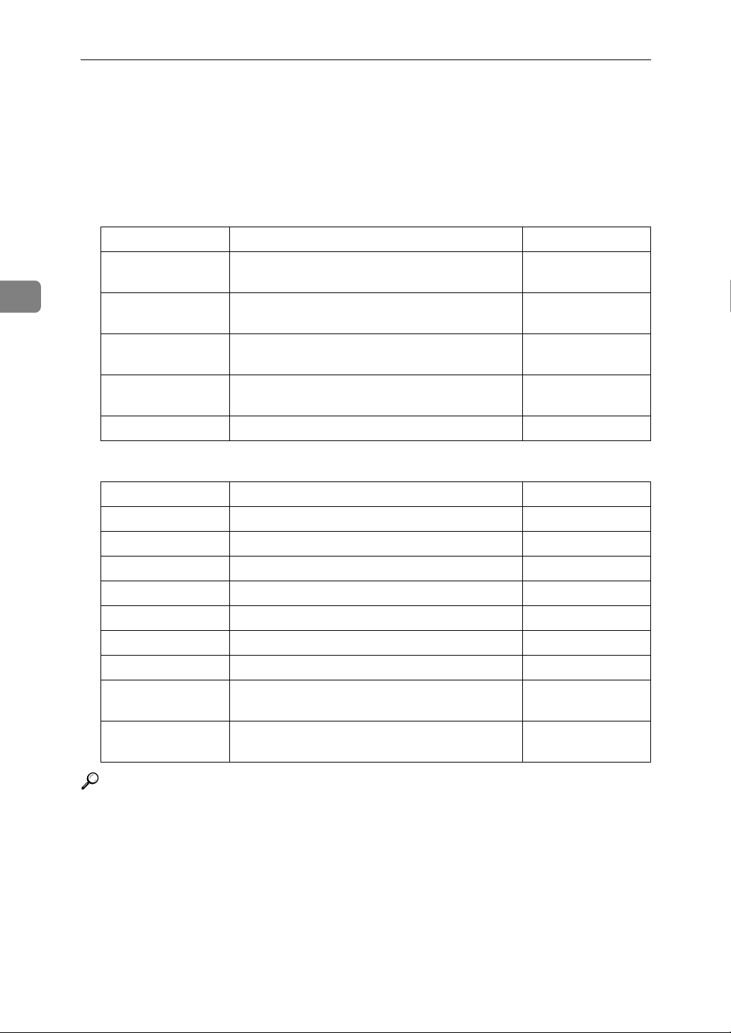
3
Copier / Document Server Features
Settings for the Document Server
This section describes user tool settings for the Document Server.
For details, see "System Settings", and "Copier / Document Server Features".
❖ Copier / Document Server Features
Heading items Default
General Features Document Server Storage Key: F1 2 Sided Original
Top to Top
General Features Document Server Storage Key: F2 1 Sided→1 Sided
Combine
General Features Document Server Storage Key: F3 1 Sided→1 Sided
Combine: 4 originals
General Features Document Server Storage Key: F4 1 Sided→1 Sided
Combine: 8 originals
General Features Document Server Storage Key: F5 Create Margin
❖ System Settings
Heading Item Default
General Features Warm up Notice On
General Features Copy Count Display Up
General Features Output: Document Server Internal Tray 1
Tray Paper Settings Paper Tray Priority: Copier Tray 1
Tray Paper Settings Cover Sheet Tray Off
Tray Paper Settings Slip Sheet Tray Off
Timer Settings Copier/Document Server Auto Reset Timer 60 seconds
Administrator
Tools
Administrator
Tools
Auto Delete File in Document Server Yes, After 3 day(s)
Delete All Files in Document Server -
Reference
p.41 “System Settings”
p.75 “Copier / Document Server Features”
92
 Loading...