

Page 1

Available Options
• Automatic Document Feeder (ADF)
• Internal 1-bin Tray (internal tray 2)
• Memory Card (2MB or 4MB)
• 400 dpi High Resolution Card
• Function Upgrade Card
• Hard Disk (80MB)
• ISDN Unit
Page 2

Caution
Use of controls, adjustments or performance
of procedures other than those specified
herein may result in hazardous radiation exposure.
Shielded interconnect cables must be employed with this equipment to ensure compliance with the pertinent RF emission limits
governing this device.
CE168X
"The ISDN kit complies with the requirements
of Commission Decision 94/797/EC"
94/797/EC:
* Comission Decision of 18 November 1994
on a common technical regulation for the
pan-European integrated service digital
network (ISDN) basic access.
Although this equipment can use either loop
disconnect or DTMF signalling, only the performance of the DTMF signalling is subject
to regulatory requirements for correct operation. It is therefore strongly recommended that
the equipment is set to use DTMF signalling
for access to public or private emergency
services. DTMF signalling also provides
faster call set up.
Note
Some illustrations may be slightly different
from your machine.
Certain options may not be available in some
countries. For details, please contact your
local dealer.
Page 3

NOTICE TO USERS (Great Britain)
This model is designed and approved for connection to the following circuits.
British T elecom Public Switched Telephone Network
Hull Public Switched Telephone Network
P ABX Extensions
Mercury Communications Limited Public Switched Telephone Network.
CONNECTION TO THE PSTN OR A P ABX EXTENSION
If there is a line jack socket already installed, you may connect this model using the line lead
supplied. If you require a socket to be fitted, complete the attached from and send it to your local
telephone manager’s office.
IMPORTANT NOTICE
1. The connection to the BT network must be unplugged before the earth is disconnected.
2. The connection to the BT network must not be hard wired.
3. Please ensure that connection to the mains supply (240Vac) is correctly made and that the
power is switched on before use.
4. The apparatus is suitable for direct connection to exclusive lines of a Public Switched Telephone Network, and for connection to compatible PABX’s (consult your authorised dealer for
the list of compatible PABX’ s and for installation thereon), or via an RBS.
The definition of an RBS (Relevant Branch System) for PSTN lines, is given in BS6789 section
6.1, clause 2.4.
5. When idle, this model allows normal use of an associated approved main telephone, which
must be plugged into the BS6312 compatible series connector, provided for connection to the
telephone line. Only one such connection may be made.
6. The apparatus must be connected to PSTN line which use the loop disconnect or DTMF signaling.
7. The machine is not suitable as an extension to payphone, for use on shared service lines, or on
1-1 carrier systems.
8. The Terminal operates in mode 1 (autodialing).
9. The user is advised to check all numbers stored in the register before making a call.
10. The approval of this terminal for connection to the British telecom public switched telephone
network is INVALIDATED if the apparatus is subject to any modification in any material way not
authorised by BABT or it is used with, or connected to:
a) Internal software that has not been formally accepted BABT.
b) External control software or external control apparatus which causes the operation of the
terminal or associated call set-up equipment to contravene the requirements of the ap-
proval.
All apparatus connected to this terminal and thereby connected directly to the British Telecom
public switched telephone network must be approved apparatus as defined in Section 22 of the
British T elecommunication ACT 1984.
Page 4

1 1. This apparatus has been approved for the use of the following facilities:
Storage of T elephone Number for Retrieval by Predetermined Code
Automatic Call Initiation
Operation in the Absence of Proceed Indication (Although not Detected)
Automatic Dialing Facilities
Auto-Calling Facility
Loudspeaking Facility
Series Connection Facility
Automatic Storage of Last Number Dialed
T one Detection-Busy T one
Repeat Attempt Facilities: Multiple(Automatic)
Auto Clear form Call Originating End
Integral Modem
Any other usage will invalidate the approval of the apparatus if, as a result, it then ceased to
conform to the standard against which approval was granted.
12. Connection to a PBX -it cannot be guaranteed that the apparatus will operate correctly under
all possible conditions connection to compatible PBX’s. Any cases of difficulty should be referred in the first instance to the supplier of the telephone apparatus.
13. This apparatus provides an off hook detector and switching of the line between the telephone
and modem. The voltage drop introduced by this apparatus into the loop connection between
the main telephone and the network at a current of 10 ma d.c. is 0.3 volts.
14. Only apparatus conforming with BS 6301 or EN 41003 may be connected to the series socket.
Any interconnection between the above socket and other connections, directly or by the way of
other apparatus, may produce hazardous conditions on the BT network.
Advice should be obtained from a competent engineer before any such connection is made.
15. With reference to EN41003 cl 4.1.3 the apparatus is supplied with a connection to the public
switched telephone network, which is referred to as TNV circuit. There is also an optional
printer port that may by fitted, which is referred to as a SELV circuit. Please ensure that the
TNV circuit is only connected to another TNV circuit and that the SELV circuit is only connected to other SELV circuits.
16. The apparatus does not recognize a secondary proceed indication.
Declaration of Conformity
“The Product complies with the requirements of the EMC Directive
89/336/EEC and the Low Voltage Directive 73/23/EEC.”
Page 5

SAFETY
Important Safety Instructions
In addition to the warnings and cautions included in the text of this manual,
please read and observe the following safety instructions.
1. Read all of these instructions.
2. Save these instructions for later use.
3. Follow all warnings and cautions marked on the product.
4. Unplug this product from the wall outlet before cleaning. Do not use liquid
cleaners or aerosol cleaners. Use a damp cloth for cleaning.
5. Do not use this product near water.
6. Do not place this product on an unstable cart, stand, or table. The product
may fall, causing serious damage to the product or injuring the user.
7. Slots and openings in the cabinet and the back or bottom are provided for
ventilation; to ensure reliable operation of the product and to protect it
from overheating, these openings must not be blocked or covered. The
openings should never be blocked by placing the product on a bed, sofa,
rug, or other similar surface. This product should not be placed in a builtin installation unless proper ventilation is provided.
8. This product should be operated from the type of power source indicated
on the marking label. If you are not sure of the type of power available,
consult an authorized sales person or your local power company.
SAFETY
9. This product is equipped with a 3-wire grounding type plug, a plug having
a third (grounding) pin. This plug will only fit into a grounding-type power
outlet. This is a safety feature. If you are unable to insert the plug into the
outlet, contact your electrician to replace your obsolete outlet. Do not
defeat the purpose of the grounding type plug. (This does not apply in
countries in which the 2-wire, non-grounded type of plug is used.)
10.Do not allow anything to rest on the power cord. Do not locate this product where persons will walk on the cord.
11.If an extension cord is used with this product, make sure that the total of
the ampere ratings on the products plugged into the extension cord does
not exceed the extension cord ampere rating. Also, make sure that the
total of all products plugged into the wall outlet does not exceed 15 amperes.
i
Page 6

12.Never push objects of any kind into this product through cabinet slots as
they may touch dangerous voltage points or short out parts that could
result in a risk of fire or electric shock. Never spill liquid of any kind on the
product.
13.Do not attempt to service this product yourself, as opening or removing
covers may expose you to dangerous voltage points or other risks. Refer
all servicing to qualified service personnel.
Please read the "SAFETY INFORMATION" section in the "General Reference" before using this machine.
ii
Page 7

Grounding
Ground the machine and the lightning protection circuit in accordance with
regulations. Do not ground to gas or water pipes, or to a telephone ground
plug. Proper grounding is to the ground terminal of the power outlet. Be sure
that the ground terminal of the power outlet is properly grounded.
The lightning protection circuit for the machine requires the machine to be
properly grounded. If proper grounding is provided, about 90% of lightning
damage can be prevented. For safety, be sure to connect the machine to a
three-prug grounded outlet.
Cold Weather Power-up
Avoid raising the room temperature abruptly when it is below 57°F(14°C), or
condensation may form inside the machine.
1. Raise the room temperature to 68°F(20°C) at less than 18°F(10°C) per
hour.
2. Wait for 30 to 60 minutes.
3. Turn the power on.
4. Do not use the machine near a humidifier.
SAFETY
Thunderstorms
With proper grounding, about 90% of lightning damage can be prevented.
However, if possible, during severe electric storms turn the power switch off
and disconnect the power cord and telephone line cord.
General
1. Since some parts of the machine are supplied with high voltage, make
sure that you do not attempt any repairs or attempt to access any part of
the machine except those described in this manual.
2. Do not make modifications or replacements other than those mentioned in
this manual.
3. When not using the machine for a long period, disconnect the power cord.
iii
Page 8

iv
Page 9

SYMBOLS AND CONVENTIONS
Conventions
IMPORTANT
Instructions designed to prevent paper jams, damage to originals, or loss of
data. Be sure to read this information.
Before operation
Tips on what to do before you start.
HINT
Advice about a particular operation or how to correct a mistake.
Restriction
Numerical limits, functions that cannot be combined or conditions in which a
particular function is disabled.
Cross-reference
Tells you where you can find related information.
[Exit]
Words enclosed in square brackets refer to the four buttons at the base of
the display . For example “Press [Exit]” means press the button directly below
the word “Exit” on the display.
Boldface
Boldface is used to refer to keys on the operation panel (except for the four
keys under the display).
BASIC
1
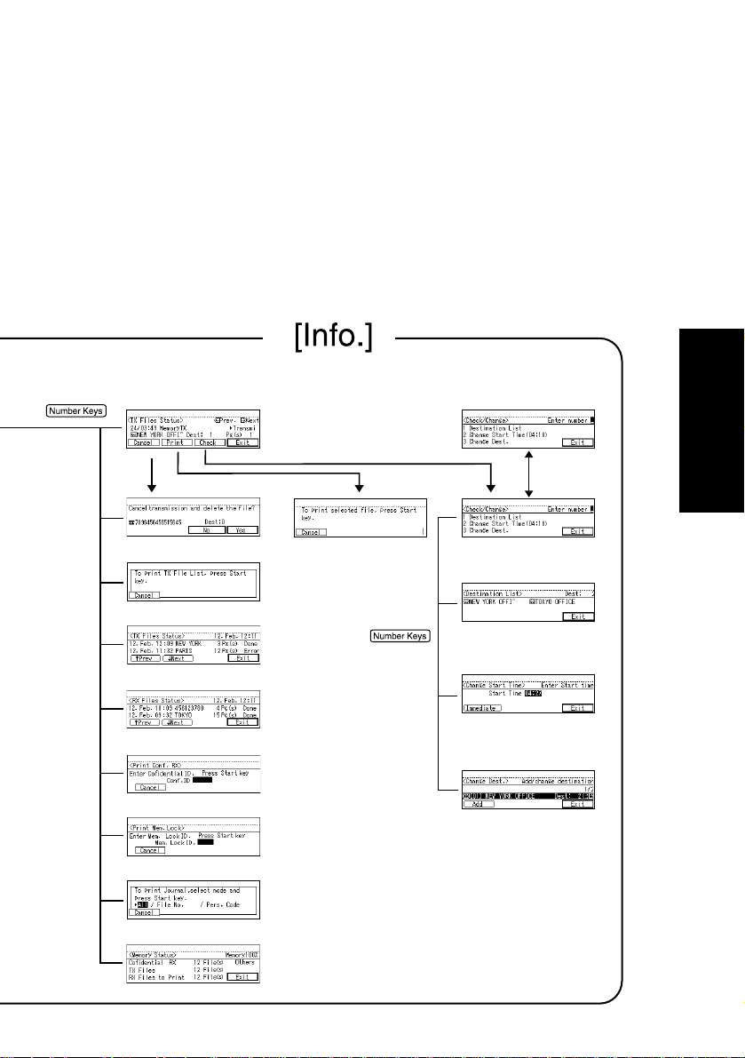
Page 10
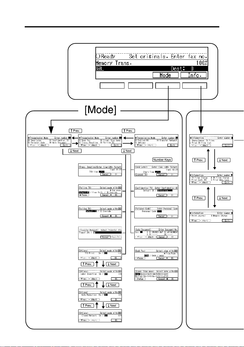
FUNCTION MAP
2
Page 11
BASIC
3
Page 12

TABLE OF CONTENTS
SYMBOLS AND CONVENTIONS.................................................................1
Conventions .........................................................................................1
FUNCTION MAP .........................................................................................2
Getting Started
GUIDE TO COMPONENTS ........................................................................10
OPERATION PANEL...................................................................................12
READING THE DISPLAY .............................................................................14
USEFUL FUNCTIONS ..................................................................................16
Auto Power-On Reception..................................................................16
Transmission With Image Rotation ....................................................17
ACCEPTABLE TYPES OF ORIGINALS ........................................................18
HOW TO SET AN ORIGINAL .....................................................................21
Sending a Fax Message
Overview ............................................................................................26
MEMORY TRANSMISSION ........................................................................27
IMMEDIATE TRANSMISSION .....................................................................34
On-hook Dial (not available in some countries)..................................37
Manual Dial (external handset option required)..................................38
SCAN SETTINGS........................................................................................39
Resolution .......................................................................................... 39
Original Type ......................................................................................40
Image Density (Contrast) ...................................................................41
Mixing Scan Settings In A Multiple Page Original...............................42
CHANGING LINE TYPE (OPTIONAL ISDN UNIT REQUIRED) ....................43
DIALING....................................................................................................45
Number Keys .....................................................................................45
Quick Dial...........................................................................................50
Speed Dial..........................................................................................51
Groups ...............................................................................................54
Optional Group Dial (Function Upgrade Card Required)....................55
Redial .................................................................................................56
4
Page 13

TRANSMISSION FEATURES ........................................................................58
Stamp ................................................................................................. 58
ID Transmission .................................................................................59
Receiving a Fax Message
IMMEDIATE RECEPTION ........................................................................... 62
MEMORY RECEPTION...............................................................................63
Substitute Reception ..........................................................................64
SELECTING THE RECEPTION MODE .........................................................66
Fax Mode (Auto Reception Mode) .....................................................66
Telephone Mode .................................................................................66
RECEPTION FUNCTIONS...........................................................................67
Transfer Station ..................................................................................67
ID Reception ......................................................................................68
PRINTING FUNCTIONS .............................................................................69
Print Completion Beep .......................................................................69
Checkered Mark.................................................................................69
Center Mark .......................................................................................70
Reception Ti me ..................................................................................70
Multi-copy Reception (Memory Card Or Hard Disk Option Required) .........71
2-Sided Printing (Optional Duplex Tray And Memory Card
Or Harddisk Required) .......................................................................71
Image Rotation...................................................................................72
Two In One.........................................................................................72
Page Separation and Length Reduction
(not available in some countries)........................................................73
Reverse Order Printing.......................................................................73
Page Reduction..................................................................................74
TSI Print.............................................................................................74
CIL/TID Print (ISDN unit required) .................................................... 74
When There Is No Paper Of The Correct Size...................................75
BASIC
Advanced Transmission Features
SEND LATER ...............................................................................................78
CONFIDENTIAL TRANSMISSION ..............................................................80
PERSONAL CODE TRANSMISSION...........................................................83
5
Page 14

SENDING AN AUTO DOCUMENT.............................................................85
BOOK FAX ................................................................................................87
CHOOSING THE AREA TO BE SCANNED YOURSELF
(IRREGULAR SCAN AREA) .......................................................................89
TRANSMISSION DEADLINE (TRD) .............................................................91
POLLING TRANSMISSION.........................................................................93
POLLING RECEPTION ...............................................................................97
TRANSFER REQUEST ............................................................................... 101
TRANSMISSION OPTIONS ..................................................................... 105
Communication Information
CHECKING AND CANCELING TRANSMISSION FILES.......................... 110
Canceling A Transmission ................................................................ 1 10
Printing A File ................................................................................... 1 11
Checking And Editing A File .............................................................1 12
PRINTING A LIST OF FILES IN MEMORY (PRINT TX FILE LIST)................ 116
CHECKING THE TRANSMISSION RESULT (TX FILE STATUS) ................... 117
CHECKING THE RECEPTION RESULT (RX FILE STATUS) ......................... 118
PRINTING A CONFIDENTIAL MESSAGE
(MEMORY CARD OR HARD DISK REQUIRED) ...................................... 119
PRINTING A FILE RECEIVED WITH MEMORY LOCK
(MEMORY CARD OR HARD DISK OPTION REQUIRED) ........................ 121
PRINTING THE JOURNAL ....................................................................... 123
DISPLAYING THE MEMORY STATUS ....................................................... 125
Troubleshooting
ERROR MESSAGES AND THEIR MEANINGS.......................................... 128
SOLVING PROBLEMS ............................................................................. 130
INDICATORS .......................................................................................... 131
When The Receive File Indicator Is Lit Or Flashing.........................131
When The i (Confidential Reception) Indicator Is Lit.....................132
When The Fax Error Indicator Is Lit .................................................132
WHEN AN ERROR REPORT IS PRINTED .................................................. 133
WHEN POWER IS TURNED OFF OR FAILS............................................... 133
6
Page 15

User Tools
ACCESSING THE USER TOOLS .............................................................. 136
REGISTER/DELETE MENU........................................................................ 138
Registering Quick Dials....................................................................138
Deleting Quick Dials.........................................................................140
Registering Groups ..........................................................................141
Deleting Groups ...............................................................................144
Registering Optional Groups
(Function Upgrade Card Option Rrequired) .....................................145
Deleting Optional Groups .................................................................148
Registering Speed Dials...................................................................149
Deleting Speed Dials........................................................................151
Storing Keystroke Programs ............................................................152
Deleting A Keystroke Program .........................................................155
Registering Auto Documents............................................................157
Deleting An Auto Document .............................................................159
Registering Irregular Area ................................................................160
Deleting An Irregular Area ................................................................162
REPORTS/LISTS ....................................................................................... 164
INITIAL SETUP TX .................................................................................... 165
INITIAL SETUP RX ................................................................................... 166
ASSIGNING USER FUNCTION KEYS ...................................................... 167
KEY OPERATOR SETTINGS ..................................................................... 169
Personal Codes................................................................................169
ECM .................................................................................................174
Memory Lock (Memory Card or Hard disk option required) ............. 174
Multistep Transfer (Optional Memory card or Hard disk requireed).. .175
Forwarding .......................................................................................177
Receiving From The Senders To Treat Differently ( Special RX Nos.) ........183
Authorized Reception.......................................................................188
Monitor Volume ................................................................................192
RTI/TTI.............................................................................................193
Registering The Economy Transmission Time .................................195
ID Code ............................................................................................196
G3 Analog Line.................................................................................197
G3 Digital Line..................................................................................199
G4 Digital Line..................................................................................200
BASIC
7
Page 16

Changeing The User Parameters.....................................................203
Printing The User Parameter List.....................................................207
Date/Time.........................................................................................207
Summer Time...................................................................................209
Counters...........................................................................................209
Paper Feed Selection.......................................................................209
RDS (Remote Diagnostic System)...................................................209
Entering Text
ENTERING AND MODIFYING TEXT........................................................ 212
A vailable Characters ........................................................................212
Keys.................................................................................................212
How To Enter Text ............................................................................214
Maintaining Your Machine
CONNECTING THE MACHINE TO A TELEPHONE LINE AND TELEPHONE .... 218
Connecting The T elephone Line .......................................................218
Connecting The Machine T o The ISDN ............................................219
REPLACING THE STAMP CARTRIDGE.................................................... 220
Appendix
OPTIONAL EQUIPMENT ......................................................................... A-3
Memory Card ...................................................................................A-3
Function Upgrade Card.................................................................... A-3
400dpi High Resolution Card............................................................ A-3
ISDN Unit ......................................................................................... A-3
SPECIFICATIONS ................................................................................... A-4
FUNCTION LIST ...................................................................................... A-5
INDEX................................................................................................... A-10
8
Page 17

Getting Started
Getting Started
9
Page 18
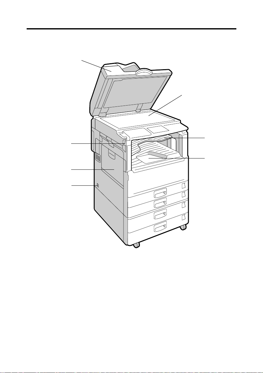
GUIDE TO COMPONENTS
a
f
b
d
i
a. ADF /Platen Cover
Holds down the original placed on
the exposure glass.
∗∗
∗1
b. Main Switch
Use to turn the machine on or off.
⇒ See “Auto Power-On Reception”
on page 16.
⇒ See “When Power is Turned Off”
on page 133.
∗∗
c
e
c. Internal 1-bin Tray (internal tray
2)
Usually received fax messages are
printed to the Internal Tray 1.
Other tray can also be selected for
other prints or copies.
⇒ See “CHANGING MACHINE
SETTINGS” in the General
Reference.
d. External Tray
e. Internal Tray 1
10
Page 19
Getting Started
h
g
f. Exposure Glass
Place the original aligning its upper
left corner with the reference mark
at the upper left corner of the
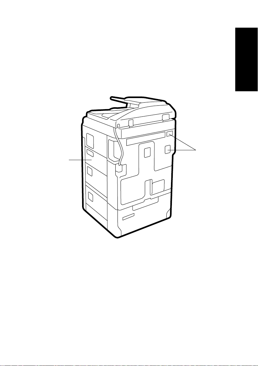
h. Line Connectors
∗∗
∗∗
∗1
∗2
∗∗
i. AC Switch
∗∗
Do not touch this switch. It should
only be used by a service engineer.
exposure glass.
g. Bypass Tray
Select this tray to use non-standard
size paper.
⇒ See “Setting Originals” in the
Copy Reference.
∗1If the main switch is on and there is still no power, turn on the AC switch.
∗2If you leave the AC switch off for more than about an hour without optional
hard disk, all files in memory are lost.
11
Page 20
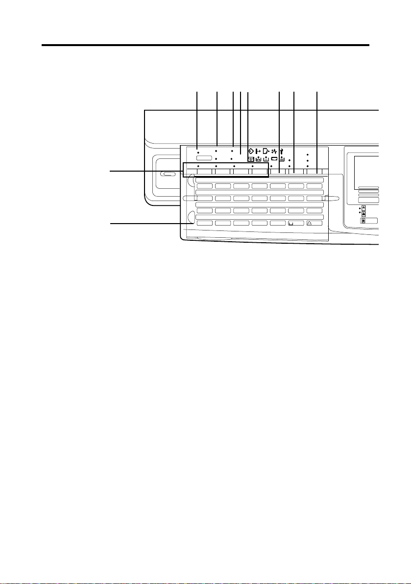
OPERATION PANEL
i
j
a. User Tools
Press to enter User Tools mode. These tools
allow you to customize the default settings.
b. Communicating Indicator
Lights during transmission or reception.
c. Receive File Indicator
Lights to tell you a message has been
received into memory. Blinks when a
Memory Lock file has been stored in
memory. Note that this indicator does not
inform you of a Confidential reception.
d. Facsimile Error Indicator
Lights if the optional Facsimile unit has
problem, there is a communication error or
there is no paper in the cassette (see page
132).
ii
e.
i (Confidential Reception) Indicator
ii
Lights when a message has been received
into memory with Confidential Reception
(see page 119, 132).
f. Stamp key
Press to turn the stamp feature on or off..
g. Transmission Mode key
Press to toggle between Memory Transmission and Immediate Transmission modes.
h. Resolution key
Press to switch between Standard, Detail
and Super Fine (optional high resolution card
required).
12
123
g
f
Standard
Immediate
Detail
Trans.
Memory
Super Fine
Trans.
a
Commu-
Start
Manual RX
nicating
Printer
Error
Receive
File
Facsimile
Error
TX Files
TEL
Status
Mode
User Tools
F1 F2 F3 F4 Stamp
A B C D E F G
H I J K L M N
OP QR S T U
VWXYZ
i. User Function keys
Each of these can be programmed for rapid
access to frequently used features.
Features Programmed by Default
Key Standard With G4 option
F1 Start Manual RX
F2 TEL Mode
Transmission
F3
Result Display
F4
−
←
←
←
G4 selection
j. Quick Dial keys
Use to dial numbers at a single touch or to
enter letters and symbols. Also use for
Group Dial, Keystroke Program and Auto
Document features.
Quick Dial Flip Plate
Flip this plate down to access Quick Dial
keys 01 through 28, flip up to access keys
29 through 56.
k. Original Type key
Use when sending a halftone image such as
a photograph or a color original.
hbc ed
aa
Page 21

aa
y
s
t
Speed Dial
On Hook Dial
Pause/
Redial
Tone
u
123
456
7809
vw
C
Copy
Facsimile
C
Getting Started
x
k
l
l. Density key (Contrast key)
Press this key to adjust the density
manually.
gg
cc
m.
g
c keys
gg
cc
Press to move the cursor or select functions
n. Tone key
Press to send tonal signals down a pulse
dialing line.
o. Pause/Redial key
Pause: Inserts a pause when you are dialing
or storing a fax number. A pause
cannot be inserted as the first digit.
Redial: Press to redial one of the last ten
numbers.
p. Number Keys
Use to dial fax numbers or enter the number
of copies.
q. Clear/Stop key
Clear: Deletes one character or digit
Stop: Interrupts the current operation
(transmission, scanning, copying or
printing).
r. Start Key
Press to start all tasks.
o
n
s. On Hook key
Use for making a phone call from the
keypad. You do not have to lift the handset.
t. Speed Dial
Press to select a Speed Dial.
u. Program key
This key is used in Copier mode.
v. Clear modes/Energy saver
Energy saver: Hold down for more than a
Clear modes: Cancels the current setting
w. Interrupt key
Interrupts the current fax operation to start
copying.
x. Facsimile key
Press to switch to fax mode.
y. Selection keys
Press these keys to make function
selections.
qprm
second to enter energy saving
mode.
and returns to standby with a
single keystroke.
13
Page 22
READING THE DISPLAY
The display tells you the machine status and guides you through operations.
• Functions that have been selected are shown white on black (e.g. ).
Keys that you can not select are shown with a dashed outline (e.g.
).
• All procedures in this manual assume you are in Fax mode. By
default, when you turn the machine on it is in Copy mode. Press
the Fax key change to Fax mode. If you wish the machine to start
in Fax mode, see “CHANGING THE MACHINE’S SETTINGS” in the
General Reference manual.
Standby display
While the machine is in the standby mode (immediately after it is turned on),
the following display is shown.
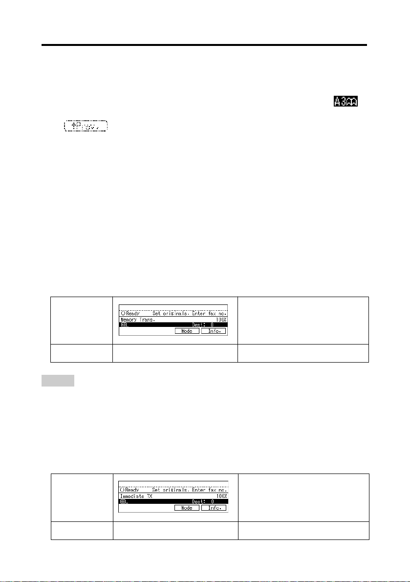
◆◆
◆Memory Transmission (Initial Display in the G3 Facsimile
◆◆
mode):
Display
ISDN option installed not installed
HINT
❑ To return the machine to standby mode, perform one of the following:
• If you have set an original and are in the sending process, remove the original.
• If you have not set an original and are in the sending process, press the Clear
modes/Energy saver key.
• If you are in User Tools mode, press the User Tools key.
◆◆
◆Immediate Transmission (G3 mode):
◆◆
Display
ISDN option installed not installed
14
Page 23
◆◆
◆Display During Memory Transmission or Memory Reception:
◆◆
Hint
❑ Even when the machine is sending or receiving a fax message from/into memory,
you can still scan the next original into memory. ⇒ See “Dual Access” on page 16.
◆◆
◆Immediate Transmission:
◆◆
Display prompts
Depending on the situation, the machine will show various prompts on the
display.
◆◆
◆Instructions and Requests
◆◆
Getting Started
◆◆
◆Questions
◆◆
◆◆
◆Selections
◆◆
◆◆
◆Status
◆◆
15
Page 24

USEFUL FUNCTIONS
Auto Power-On Reception
To save on power costs, turn off the main switch when the machine is not
used for long periods of time, such as at night or during holidays.
Even if the main switch is turned off, the machine can still send from memory,
receive or print fax messages as long as the AC switch is turned on.
By default, the machine will immediately print any messages it receives while
the main switch is off. If you wish, you can choose to have messages stored
in memory and then printed when you turn the main switch back on (see User
Parameters, page 203).
IMPORTANT
❑ When both the main and AC switches are off, and reception is disabled.
Dual Access
The machine can even while sending a fax message from memory , automatically print a report, or scan other messages into memory. Since the machine
starts sending the second message immediately after the current transmission terminates, the line will be used efficiently.
Note that during Immediate Transmission or when in User Tools mode, the
machine cannot scan an original.
Personal Code Access
The machine can be set up so that nobody can use it without entering a
personal code. This prevents unauthorized people from sending fax messages and can be used to track Fax machine use by giving a personal code to
each user.
Hint
❑ Register personal codes and turn Personal Code Access on with the User Tools
(see User Parameters, page 203). The default setting is off.
❑ Even if Restricted Access is enabled, the machine can receive and print a fax
message. Personal codes appear on reports as “****”.
16
Page 25
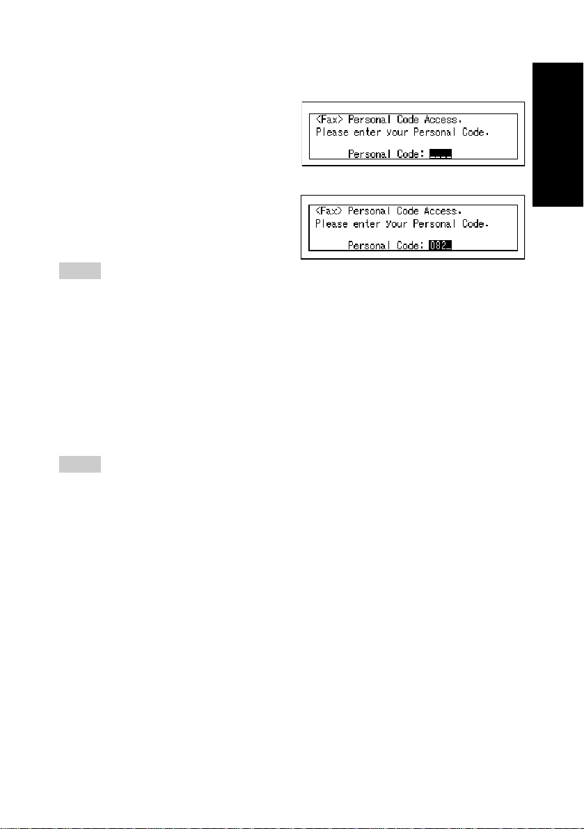
Entering a Personal Code
If Personal Code Access is
turned on, the display is shown
1
as opposite:
Enter a personal code (4-digit
number) using the number keys.
2
Hint
❑ If a user enters a personal code that is not registered, the machine returns to step 1.
Transmission With Image Rotation
For most purposes, set A4/LT originals in the sideways direction (L).
If you set an A4/LT original in the lengthwise direction (K), the image will be
sent rotated by 90°. Providing the receiver has A4/LT sideways paper(L),
the message will be printed the same size as the original.
Hint
❑ If you wish to set the original in A4/LT lengthwise direction (K), set the original
upside down. The TTI will be printed on the upper of the received fax message.
❑ When Image Rotation is used, all messages are sent by nomal Memory Transmis-
sion.
Getting Started
17
Page 26

ACCEPTABLE TYPES OF ORIGINALS
If you set an original containing wet ink or correcting fluid, the exposure glass will
be marked and copies will be affected. To avoid this, make sure your originals
are dry.
Acceptable Original Sizes
Name
Exposure glass
ADF
Size
Maximum A3 (297 × 420 mm),
11" × 17" (279 × 432 mm)
Fax transmission: A5K to A3 L (up to
1200 long)
8½" × 5½"K to 11" × 17" (DTL)L
Number of
sheets
30 sheets
Paper
thickness
52~105g/m
(45~90kg)
Unacceptable Paper for the ADF
❑ If originals in any of the following conditions are placed in the ADF, they may be
damaged. Place them on the exposure glass.
· Originals of sizes other than those specified above table
· Originals containing staples or clips
· Perforated or torn originals
· Curled, folded, or creased originals
· Pasted originals
· Originals with any kind of coating, such as thermosensitive paper, art paper,
aluminum foil, carbon paper, or conductive paper
· Originals with indexes, tags, or other projecting parts
· Sticky originals such as translucent paper
· Thin and soft originals
· Originals of inappropriate weight (⇒ See the above table.)
· Originals in bound form such as books
· Transparent originals such as OHP transparencies or translucent paper
· Originals of in appropriate weight
2
Restriction
❑ Do not use different sizes of original in the same transmission.
18
Page 27
Originals whose sizes are difficult to detect
❑ If originals in any of the following conditions are sent, the size is difficult to detect.
The receiving machine may not select paper of the correct size.
· Originals with indexes, tags, or projecting parts
· Transparent originals such as OHP transparencies or translucent paper
· Dark originals with many characters or drawings
· Originals which partially contain solid printing
· Originals which have solid printing at their edges
· Originals other than those (with
o) in the tables below.
❑ The following paper sizes are automatically detected (in fax mode)
Paper size A3 B4 A4 B5 A5 A5 B6 11"×17" 8 1/2"×14" 8 1/2"×11 " 8 1/2"×11"
Where original L L KLKL K L KL L L KL K
is placed
Exposure glass ❍❍❍❍❍×× ❍❍ ❍ ❍
ADF ❍❍❍❍❍ ×× ❍❍ ❍ ❍
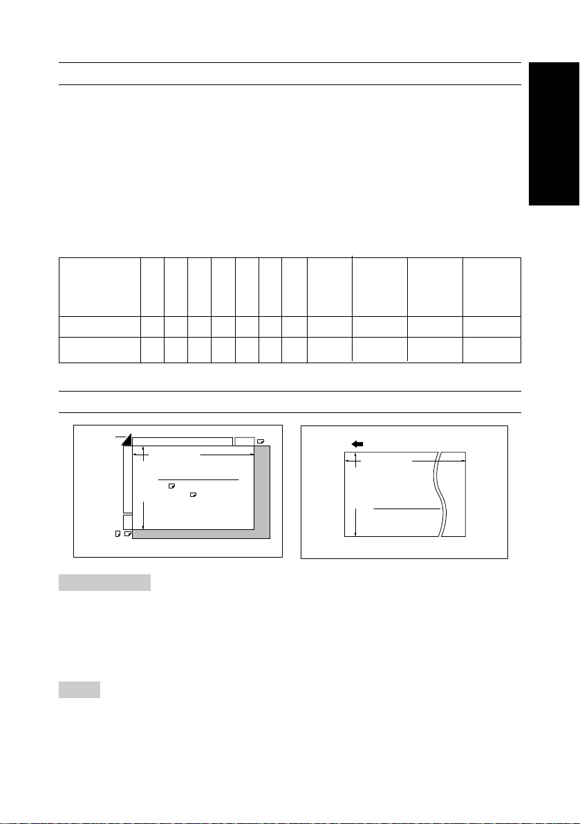
Paper Size and Scanned Area
Reference
position
Horizontal size
Vertical size
Maximum Scaning area
A3 (297 x 420mm)
11" x 17" (279 x 432mm)
A3
A4
Exposure glass
A3
Feed direction
Horizontal size
Vertical size
Maximum Scaning area
297~1260mm
ADF
Getting Started
Restrictions
❑ There may be a difference in the size of the image when it is printed at the desti-
nation.
❑ If an original larger than DLT A3 is placed on the exposure glass, only the DLT A3
area is scanned.
Hint
❑ Even if an original is correctly placed on the exposure glass or in the ADF, a
margin of 3mm around each edge of the original may not be sent.
❑ If the receiver uses paper narrower than the original, the image will be reduced to
fit the paper width.
19
Page 28

❑ If an original larger than the above maximum scanning area, do one of the follow-
ing.
· Change the user parameter (see page 203)
· Specify the irregular scan area (see page 160)
The machine detects paper sizes in the following ways:.
❑ When you set an original in the ADF, an original wider than about 190 mm is scanned
as A4 size wide. An original narrower than about 265 mm is scanned as B4 size
wide. An original wider than about 265 mm is scanned as A3 size. Originals narrower
than 190 mm will be sent as A4 size. Originals up to 1200 mm in length can be
scanned. Widths between 227 and 228 mm cannot be identified correctly as widths
of A4 or B4 size.
❑ When you set an original on the exposure glass, an original wider than about 70 mm
is scanned as A4 size wide. An original narrower than about 261 mm is scanned as
B4 size wide. Originals wider than 262 mm are scanned as A3 size. Originals narrower than 70 mm will be sent as A4 size. Normally, lengths up to a maximum of 420
mm can be scanned (this figure varies slightly depending on the type of original). If
you select Irregular Scan Area, lengths up to 432 mm are possible. If the width is
between 237 to 249 mm, the machine cannot detect the size correctly.
1. The maximum scan area for Memory Transmission is 297 mm × 432 (A3), 11" ×
17(DLT) mm.
2. Immediate Transmission from the ADF, check the table below.
Width Length
Resolution
Standard 1200 1200
Detail 600 1200
A4
B4
A3
Fine Not available 1200
Super Fine Not available 600
Standard 1000 1200
Detail 500 1200
Fine Not available 1200
Super Fine Not available 500
Standard 800 1200
Detail 432 1200
Fine Not available 800
Super Fine Not available 432
Without 400dpi High
Resolution Card
With 400dpi High
Resolution Card
3. When sending from the exposure glass, the maximum scan area is 1 1" × 17"(DLT)
297 mm × 432 (A3) mm.
20
Page 29
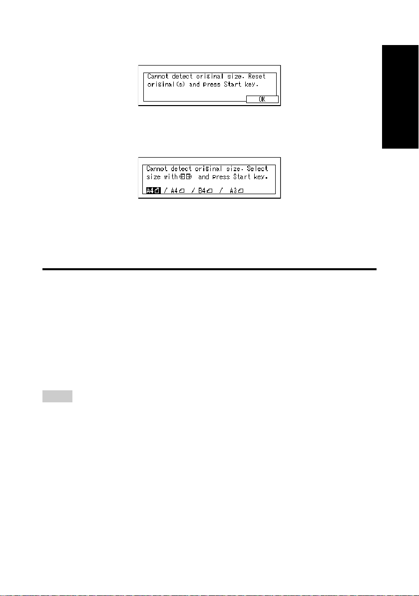
If the machine cannot detect the original size, the following display is shown:
Remove the original and replace it on the exposure glass. Press the Start
key to scan the original again. If the machine still cannot detect the original
size, the following display is shown:
Press the < and > keys to switch the scan size and press the Start key
again.
HOW TO SET AN ORIGINAL
In this manual an original can mean a single or multiple page document.
You can set your originals either in the ADF (Auto Document Feeder) or on
the exposure glass. Some types of orignals are unsuitable for the ADF so
they must be set on the exposure glass (see “Acceptable Types of Originals”
on page 18).
Which way you place your original depends on its size and whether you are
using the ADF or the exposure glass. Check the diagrams below.
Hint
❑ When sending a fax, the image output at the other end depends on the size and
direction of paper used in the receiver’s terminal. If the receiver does not use
paper of the same size and direction as that of the original, the fax image may be
output reduced, trimmed at the both edges, or divided into two or more sheets.
When sending an important original, we recommend you to ask the receiver about
the size and direction of the paper used in their terminal.
❑ When sending an original of a irregular (non-standard) size or part of a large original, you
can specify the scan area precisely (see “Specifying an Irregular Scan Area” on page
160).
Getting Started
21
Page 30
◆◆
◆How to set A4, B4, A3, LT, LG or DLT size originals:
◆◆
Original
Exposure glass
ADF
Hint
❑ If you set an A4/LT original using the lengthwise direction(K), it is sent rotated by
90 degrees ⇒ see “Transmission with Image Rotation” on page 17.
If you set the original upside down as shown in the diagram, the TTI will appear on
the top of the image at the destination ⇒ see “TTI print” on page 105.
◆◆
◆How to set A5 or B5 size originals:
◆◆
Original
Exposure glass
ADF
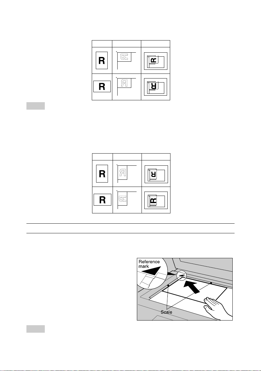
Setting a Single Page on the Exposure Glass
Set originals that cannot be placed in the ADF on the exposure glass one
page at a time.
Lift the platen cover or ADF by
at least 30 degrees. Place the
1
original face down and align its
upper left corner with the reference mark at the upper left corner of the exposure glass.
Hint
❑ If you do not raise the platen cover/ADF by at least 30 degrees the original size
will not be detected.
22
Page 31

Close the platen cover or ADF.
2
Hint
❑ When sending a bound original, the received image may contain some black ar-
eas. To reduce this effect, hold down the original to prevent its bound part from
rising.
Setting an Original in the ADF
Multiple page originals can be placed in the ADF. The machine scans the
originals one by one.
Restriction
❑ Place all the originals to be sent in the ADF all at once. When sending a fax, the
originals cannot be placed in the ADF one by one or in sheaves.
Hint
❑ When setting pages longer than A3 (420mm)/DLT (17") in the ADF, guide them in
with your hand. If you press down on the original or if it is curling up slightly it
might jam.
❑ If an original larger them the maximum scanning area, do one of the followings.
· Change the userparameters
· Specify the Irregular scan ared.
❑ When setting originals longer than A3 (420mm)/DLT (17"), use the “Irregular pa-
per size” setting. If you handle long originals frequently, you can specify that the
machine accepts originals longer than A3 (420mm)/DLT (17") from the ADF automatically. If you choose this setting and there is a paper jam while scanning, the
originals will still be sent. However, there is a posibility that the original will be
damaged. For more details refer to “Irregular Scan Area” on page 160 and User
Parameters on page 203.
❑ If your message is bent or folded, flatten it before you set it.
❑ Set thin originals on the exposure glass.
Getting Started
Cross-reference
❑ For information about the sizes and number of originals that can be placed in the ADF,
23
Page 32

“ACCETABLE TYPE OF ORIGINALS” on page 21.
Adjust the original guide to
match the size of your original.
1
Align the edge of your originals
and stack them in the ADF face
up.
Hint
❑ If you insert the original too far from the ADF, the paper size may not be detected
properly.
24
Page 33

Sending a Fax Message
Message
Sending a Fax
25
Page 34

Overview
The basic procedure to send a fax message is:
1 Make sure the Fax indicator is lit
2 Set your original
3 Dial the number
4 Press Start
The rest of this section describes these steps and the various features that
are available in more detail.
There are two ways to send a fax message:
q
Memory Transmission
q
Immediate Transmission
You can check the indicators on the operation panel to check which mode is
currently active and press the Transmission Mode key to toggle between
them.
26
Page 35

MEMORY TRANSMISSION
After you press the Start key, the machine scans all pages of your message
before it starts dialing. Memory Transmission is useful when you are in a
hurry and do not want to spend too long waiting by the machine. It also allows
you to send the same message to several destinations (Broadcasting).
IMPORTANT
❑ If there is a power failure or the plug is pulled out for more than 1 hour, all the files
stored in memory are deleted. If this happens, as soon as you switch back on the
Power Failure Report (see page 133) is printed to help you identify deleted files. If
you turn just the main switch off, files are not deleted.
Hint
❑ Place the original you want to store in memory on the exposure glass or the ADF.
To store multiple page originals from the exposure glass, set them page by page.
❑ You can scan half the pages of your original from the exposure glass and the
remainder from the ADF. When you have finished scanning from the exposure
glass, place the rest of the pages in the ADF and press Start.
❑ The default transmission mode when the machine is turned on or when modes
are cleared is Memory Transmission. You can change this with the User Tools (see
page 203).
❑ As default, the machine will return to the default transmission mode (Memory)
after every transmission. You can change this so that the current mode is maintained with the User Parameters (page 160).
Message
Sending a Fax
Restrictions
❑ If memory is full (0% appears on the display), Memory Transmission is disabled.
Use Immediate Transmission instead.
❑ The number of pages that can be stored in memory depends on the original
images and the scan settings. You can store up to 80 standard pages (ITU-T No.
1 chart, Resolution: Standard, photo mode: OFF).
❑ Maximum number of Memory Transmission files : 200
Maximum number of destinations per Memory Transmission : 200
Combined total number of destinations that can be stored : 500
27
Page 36

Commu-
Make sure that the Memory
Transmission indicator is lit.
1
❑ If it isn’t, press the Transmis-
sion Mode key.
User Tools
Start
F1 F2 F3 F4 Stamp
Manual RX
nicating
Printer
Error
TEL
Mode
Receive
File
Facsimile
Error
TX Files
Status
123
Trans.
Memory
Trans.
Detail
Super Fine
Standard
Immediate
Set the original.
2
Hint
❑ The original can be placed at any time up until you press the Start key.
❑ You can send the first part of an original from the exposure glass then the second
part from the ADF. After you place the last page on the exposure glass, you have
60 seconds to insert the remainder of the original in the ADF.
Note that you cannot set pages on the exposure glass after you have started
using the ADF.
Cross-reference
“How to Set an Original” ⇒ See page 22.
Select the scanning conditions
(resolution, density and origi-
3
nal type, see page 39).
Dial. If you wish to send the
same message to more than
4
one destination, press [Add] and
dial another destination. Repeat
this step for all destinations.
❑ If you make a mistake, press the
Clear key and re-enter the correct number.
28
Page 37

Hint
❑ When dialing with the number keys or using Chain Dial (page 49), you can select
the G3 or G4 before pressing [Add] in step 4.
Cross-reference
“Dialing” ⇒ See page 45.
“Facsimile User Tools” ⇒ See page 135.
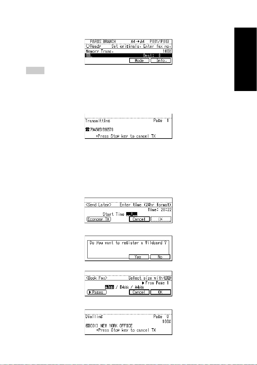
Press the Start key.
❑ The machine starts scanning
5
“see Registering the RTI/CSI” ⇒ See
page 135.
the original.
❑ The machine calls the destina-
tion. While it is dialing, the number that you dialed is shown on
the display.
Cross-reference
❑ After transmission the machine
will return to standby mode.
Message
Sending a Fax
29
Page 38

◆◆
◆Canceling a Memory Transmission
◆◆
❑ To cancel a Memory Transmission before it is sent (before pressing the Start
key), press the Clear Modes/Energy Saver key.
❑ To cancel a Memory Transmission while the original is being stored in memory
(after pressing the Start key), press the Clear/Stop key. The machine stops
storing the original. All the scanned data is canceled and not sent.
❑ To cancel a Memory Transmission after it has been stored in memory or while it is
being transmitted, see page 110.
Hint
❑ If you cancel a Memory Transmission after communication starts, some pages
may already sent to the destination.
❑ If the transmission finishes while you are still trying to cancel it, the message has
already still be sent and cannot be canceled.
Cross-reference
❑ For more information, see “Checking and Canceling the File Settings” on page
110.
◆◆
◆Checking the transmission result
◆◆
❑ Turn the Transmission Result Report (Memory Transmission, see page 27) on if
you want a report to be printed after every successful transmission. If you leave it
off, a report will not be printed after every transmission, but should a transmission
fail, a Communication Failure Report will be printed.
❑ If you turn the Transmission Result Report (Memory Transmission) off, the Error
Report will be printed when the communication on fails.
❑ You can also check the transmission result by examining the Journal (Transaction
Confirmation Report, page 123).You can either print it or scroll through it on the
display. ⇒ See “Displaying the Transmission Result” on page 117.
◆◆
◆Sending a fax message immediately
◆◆
To send a fax message immediately, use Immediate Transmission.
If you have just set up a original for broadcasting, the immedicate transmission file will interrupt the current communication.
If there are files queued in addition to the file being currently sent, your
original is not be sent until the queued files have been sent.
30
Page 39

◆◆
◆Automatic Redial
◆◆
If a fax message could not be transmitted because the line was busy or an
error occured during transmission, redialing is done 4 times at 5 minutes
intervals (these figures vary according to which country you are in).
If redialing fails after four redials, the machine cancels the transmission
and prints the Transmission Result Report (see page 33) or the Communication Failure Report (see page 33).
◆◆
◆Broadcasting Sequence
◆◆
If you dial several destinations for the same message (Broadcasting) the
messages are sent in the order in which they were dialed. If the fax message could not be transmitted, the machine Redials that destination after
the last destination specified for Broadcasting. For example, if you specify
four destinations A through D for broadcasting, and if the lines to the destinations A and C are busy , the machine dials the destinations in the following order: A, B, C, D, A, and C.
◆◆
◆Broadcasting: checking the progress
◆◆
To check up to which destination the fax message has been sent during
Broadcasting, print the TX file list (see page 111).
◆◆
◆If memory runs out while storing an original
◆◆
If you run out of memory while storing an original (free space reaches 0%),
If you wish to send only scanned page, “Memory full” is displayed.
Press [OK] to return to the previous display.
Message
Sending a Fax
Hint
❑ By default, successfully scanned pages are sent. If you wish to change this set-
ting, please contact your service representative.
◆◆
◆Batch Transmission
◆◆
If you send a fax message by Memory Transmission and there is another
fax message waiting in memory to be sent to the same destination, that
message is sent along with your original. Several fax messages can be
sent with a single call eliminating the need for several separate calls. This
helps save communication costs and reduce transmission time.
Fax messages for which the transmission time has been set in advance
are sent by batch transmission when that time is reached.
Hint
❑ By default Batch Transmission is switched on. You can switch it on or off with the
User Parameters (page 203).
31
Page 40

◆◆
◆ECM (Error Correction Mode)
◆◆
This feature automatically resends data that wasn’t transmitted successfully using a system that complies with international standards.
ECM requires that the destination machine has the same feature.
Hint
❑ By default ECM is on. You can change this with the User Parameters (see page
203).
◆◆
◆Parallel Memory Transmission
◆◆
This function dials while the original is being scanned. Standard Memory
Transmission stores the original in memory, then dials the destination.
Parallel Memory Transmission allows you to quickly determine whether a
connection was made. In addition, this function scans the original faster
than Immediate Transmission and is useful when you need to use the
original for another purpose in a hurry.
Hint
❑ By default this feature is turned on. You can change this with the User Parameters
(see page 203).
Restriction
❑ Standard Memory Transmission is used instead of Pararel Memory Transmission
when:
• The line is not connected due to a busy line
• Send Later is used
• Transfer Request is used
• You store an original for Memory Transmission while another communication is in
progress
• Two or more destinations are specified
• Only an Auto Document is sent
• When the original is set on the exposure glass
❑ If the Clear/Stop key is pressed, the original jams, or memory becomes full dur-
ing Pararel Memory Transmission, the machine stops the transmission then prints
the Transmission Result Report (Memory Transmission) and erases the file.
❑ Pararel Memory Transmission print page numbers. For example, P1, P2.
Hint
❑ If you run out of memory, normal Memory Transmission takes place. When and if
this happens varies depending on the various options you have installed.
32
Page 41

Memory Storage Report
This report is printed after storing an original in memory. It helps you review
the contents and the destinations of stored originals. Even if the machine is
set up not to print this report, if an original could not be stored this report is
printed.
Hint
❑ This function can be turned on - see page 203.
❑ You can choose whether to include part of the original image on the report − see
page 203. The default setting is on.
Transmission Result Report (Memory Transmission)
This report is printed when a Memory Transmission is completed so you can
check the result of the transmission. If two or more destinations are specified,
this report is printed after the fax message has been sent to all the destinations. If the machine is set up not to print this report and the fax message
could not be successfully transmitted, the Communication Failure Report is
printed (see page 33).
Hint
❑ By default this function is turned off. To turn it on, see page 203.
❑ You can choose whether to include part of the original image on the report - see
page 203. The default setting is on.
Message
Sending a Fax
Communication Failure Report
This report is only printed if the Transmission Result Report is turned off and
a message could not be successfully transmitted with Memory T ransmission.
Use it to keep a record of failed transmissions so you can resend them.
Hint
❑ You can choose whether to include part of the original image on the report - see
page 203. The default setting is on.
33
Page 42

IMMEDIATE TRANSMISSION
After you press the Start key, the number is dialed straight away. Each page
is transmitted as soon as it has been scanned. The next page is not scanned
in while the current page is being transmitted.
Immediate Transmission is useful if you want immediate confirmation that the
message is being sent to the correct destination (just check the other terminal’s
RTI or CSI during transmission).
Hint
❑ The original is not stored in memory. Only one destination can be dialed.
❑ Place the original on the exposure glass or in the ADF. To send two or more pages
from the exposure glass, set them page by page.
❑ You can scan half the pages of your original from the exposure glass and the
remainder from the ADF. When you have finished scanning from the exposure
glass, place the reminder of the pages in the ADF and press Start.
❑ The default transmission mode when the machine is turned on or when modes
are cleared is Memory Transmission. You can change this with the User Parameters (see page 203).
❑ As default, the machine will return to the default transmission mode (Memory)
after every transmission. You can change this with the User Parameters so the
current mode is maintained.
Check that the Immediate
Transmission indicator is lit.
1
❑ If it is not lit, press the Trans-
mission mode. key.
Set your original.
Manual
Reception
F1 F2 F3
Receive
Mode
TX Files
Status
12 3
2
Hint
❑ You can set the original any time up until you press the Start key.
Cross-reference
“How to Set an Original” ⇒ See page 22.
Select any scan settings you
require (see page 39).
3
34
Page 43

Dial.
❑ If you make a mistake, press the
4
❑ If you are dialing with the number keys or by Chain Dial (see page 49), you can
Clear key and re-enter the correct number.
Hint
select G3 or G4 (communication mode).
Cross-reference
“Dialing” ⇒ See page 45.
“Selecting a Line” ⇒ See page 135.
Press the Start key.
❑ The machine starts scanning
5
see “Registering the RTI/CSI” ⇒ See page 135.
the original.
❑ The machine calls the destina-
tion. While it is dialing, the number that you dialed is shown on
the display.
Cross-reference
❑ After transmission the machine
will return to standby mode.
Message
Sending a Fax
35
Page 44

◆◆
◆Canceling an Immediate Transmission
◆◆
• If you haven’t pressed the Start key yet, press the Clear Modes/En-
ergy Saver key. If you have set the original, removing it will also cancel
Immediate Transmission.
• If you have pressed the Start key and the machine is dialing or transmit-
ting, press the Clear/Stop key and remove the original. Some pages
may have already been sent.
◆◆
◆If the destination could not be connected to
◆◆
If it was not possible to make a
connection with the number you
dialed (for example if the line was
busy or there is a line problem),
the display opposite appears:
• If you press [Memory Trans.], the machine will scan all the originals into
memory. When finished, it will begin redialing the destination and, if possible, send the message from memory.
• If you press [Cancel] then [OK] the transmission will be canceled.
◆◆
◆ECM (Error Correction Mode)
◆◆
This feature automatically resends data that wasn’t transmitted successfully using a system that complies with international standards. ECM requires that the destination machine has the same feature.
Hint
❑ By default, ECM is on. You can change this with User Parameters (see page 207).
Transmission Result Report (Immediate Transmission)
If you turn this report on, a report will be printed after every Immediate Transmission so you have a record of whether the transmission was successful or
not. If the machine is set up not to print this report and the fax message could
not be successfully transmitted. The Error report is printed.
Hint
❑ By default this report is turned off. Switch it on with the User Parameters (see
page 207).
36
Page 45

On-hook Dial (not available in some countries)
This is just like using the external handset, except you do not have to pick up
the handset before dialing. Just press the On Hook Dial key and dial the
number. If you hear a voice, you can pick up the handset and speak with the
other party.
Restriction
❑ The machine cannot dial on ISDN lines.
Place the original and select any
scan settings you require.
1
Cross-reference
“How to Place an Original” ⇒ See page 22.
“Selecting the Scan Settings (Resolution, Density and Original Type)” ⇒ See page 39.
Press the On Hook Dial key.
❑ Y ou will hear a low tone from the
2
internal speaker. If you wish to
cancel this operation, press the
On Hook Dial key again.
Message
Sending a Fax
Dial.
❑ The machine immediately dials
3
4
the destination. If you make a
mistake, press the On hook dial
or Clear/Modes key and return
to step 2.
When the line is connected and
you hear a high-pitched tone,
press the Start key.
❑ If you hear a voice, pick up the
handset before you press the
Start key and notify the destination that you want to send a
fax message (ask them to
switch to Fax mode).
37
Page 46

❑ After transmission the machine
will return to standby mode.
Manual Dial (external handset required)
Pick up the handset or an externally connected telephone handset and dial.
When the line is connected and you hear a high-pitched tone, press the Start
key to send your fax message. If, on the other hand, you hear a voice at the other
end, continue your converstaion as you would normally over the telephone.
Restriction
❑ The machine can not dial on ISDN lines.
Place the original and select any
scan settings you require (see
1
page 22).
Pick up the handset.
❑ You will hear a tone from the
2
3
external handset.
Dial.
❑ If you make a mistake, replace
the handset and try again from
step 2.
When the line is connected and
you hear a high-pitched tone,
4
press the Start key.
❑ The machine starts sending the
fax message. If you hear a voice,
pick up the handset before you
press the Start key and notify
the destination that you want to
send a fax message (ask them
to switch to Fax mode).
Replace the handset.
❑ After transmission the machine
5
38
will return to standby mode.
Page 47

SCAN SETTINGS
Y ou may wish to send many dif ferent types of fax message. Some of these may
be difficult to reproduce at the other end. However, your machine has three
settings that you can adjust to help you transmit your document with the best
possible image quality .
◆◆
◆Resolution:
◆◆
Standard, Detail, Super Fine (option)
◆◆
◆Image density:
◆◆
Auto Image Density, Manual Image Density (7 levels)
◆◆
◆Original type:
◆◆
Text, Photo/Text, Photo
Resolution
Images and text are scanned into the machine by converting them to sequences
of dots. The frequency of dots determines the quality of the image and how long
it takes to transmit. Therefore, images scanned at high resolution (Super Fine)
have high quality but transmission takes longer. Conversely, low resolution
(Standard) scanning results in less quality but your original is sent more quickly .
Choose the setting that matches your needs based upon this trade off between
speed and image clarity.
Restriction
❑
If the receiver’s machine does not support the resolution at which you are sending, the
machine automatically switches to a resolution which is supported.
Sending with Super Fine resolution requires that and your machine has the High Resolution Card option, and the destination has capability to receive fax message at Super
Fine resolution.
Message
Sending a Fax
Hint
❑ When the machine is turned on or modes are cleared, the resolution is set to Standard by
default. You can change this with the User Parameters (see page 203).
❑ By default, the resolution returns to the default after every transmission. You change
this with the User Parameters (see page 203) so that the current resolution is
maintained.
◆◆
◆Standard (8 × 3.85 lines/mm, 200 × 100dpi)
◆◆
Select for originals containing normal sized characters (e.g. handwriting or
typewritter7).
◆◆
◆Detail (8 × 7.7 lines/mm, 200 × 200dpi)
◆◆
Select for originals containing small characters or when you require greater
clarity. This resolution is twice as fine as Standard.
39
Page 48

◆◆
◆ Super Fine (16 × 15.4 lines/mm, 400 × 400dpi)
◆◆
The High Resolution Card option is required for this mode.
Select for originals with very fine details or when you require the best possible image clarity. This resolution is eight times as fine as Standard.
Press the Resolution key to
switch between resolutions. The
1
indicators above show the current
nicating
Printer
Error
TEL
Mode
Receive
File
Facsimile
Error
TX Files
Status
123
User Tools
Start
F1 F2 F3 F4 Stamp
Manual RX
Immediate
Trans.
Memory
Trans.
Standard
Detail
Super Fine
Commu-
selection.
Original Type
If your original contains photographs, illustrations or diagrams with complex
shading patterns or grays, select the appropriate Original Type to optimize
image clarity.
Restriction
❑ If you select Photo/Text or Photo, the Resolution is automatically set to Detail.
Even if you select Standard again, the image density will not return to Standard.
❑ If you select Photo or Photo/Text, you cannot select Auto Image Density.
Hint
❑ If you select Photo/Text or Photo, the transmission will take longer than when Text
is selected.
❑ If you send a fax message with Photo/Text or Photo, the background of the received
image may be marked. If this happens, lower the density and re-send the fax.
❑ When the machine is turned on or modes are cleared, Original Type is set to Text.
You can change this with the User Parameteres (see page 203).
❑ As default, the machine returns to the default Original Type after every transmis-
sion. You can change this with the User Parameters so that the current Original
Type is maintained.
◆◆
◆Text (Default Setting)
◆◆
Text is selected when the Photo and Photo/Text indicators are NOT lit.
Select Text to send an original containing a high-contrast black-and-white
image such as text. Use this setting even if your original contains text and
photographs if you only want to send clearer text.
◆◆
◆Photo/T ext
◆◆
Photo/Text is selected when the UPPER Original Indicator (aa) is lit.
Select Photo/text to send an original containing both a high-contrast blackand-white image, such as text, and a halftone image such as a photograph.
40
Page 49

◆◆
◆Photo
◆◆
Photo is selected when the LOWER Original indicator ( ) is lit.
Select Photo to send an original containing a halftone image such as a
photograph or a color original.
a
Press the Original Type
( ) key until the indicator
1
matching the type you require
is lit.
❑ When both indicators are not lit,
the Original Type is Text.
a
Image Density (Contrast)
The text and diagrams in your original must stand out clearly from the paper
they are written on. If your original has a darker background than normal (for
example, a newspaper clipping), or if the writing is faint, adjust the image
density.
By default, this machine will automatically select a density setting appropriate to the original (Auto Image Density). However, should you wish to change
the density yourself, use Manual Image Density.
◆◆
◆Auto Image Density
◆◆
The machine automatically selects an image density which is the most
appropriate for the original.
❑ By default, Auto Image Density is selected when the machine is turned
on or modes are cleared. You can change this with the User Parameters
(see page 203).
Message
Sending a Fax
a
If the Auto Image Density indicator is not lit, press the l key
1
to turn it on.
◆◆
◆Manual Image Density
◆◆
Use the Image Density keys to increase or decrease the image density
within 7 levels.
Press the iorj key to change
the density. The indicators
1
above the keys show the level.
a
a
a
41
Page 50

Mixing Scan Settings in a Multiple Page Original
When sending an original consisting of several pages, you can select different Image Density, Resolution and Original T ypes for each page.
Set your original, select the scan settings for the first page, dial and press
Start as you would normally. Then follow one of the following two procedures.
When the original is placed on the exposure glass
Restriction
❑ Select density , resolution and original type while the machine is bleeping (for about
60 seconds in Memory Transmission, 15 seconds in Immediate Transmission).
The remaining time is shown on the display.
Commu-
1 Remove the previous page and
place the next page.
2 Select the Image Density, Reso-
lution and Original type.
When the original is placed in the ADF
1 Select the Image Density, Reso-
lution and Original Type before the
next page is scanned.
User Tools
Start
F1 F2 F3 F4 Stamp
Manual RX
aa
User Tools
Start
F1 F2 F3 F4 Stamp
Manual RX
nicating
Printer
Error
Commu-
nicating
Printer
Error
TEL
Mode
TEL
Mode
Receive
File
Facsimile
Error
Receive
File
Facsimile
Error
TX Files
Status
TX Files
Status
123
123
Trans.
Memory
Trans.
Immediate
Trans.
Memory
Trans.
Detail
Super Fine
Standard
Detail
Super Fine
Standard
Immediate
42
aa
Page 51

CHANGING LINE TYPE (OPTIONAL ISDN UNIT
REQUIRED)
This machine comes with a single Analog (PSTN) line connection for G3
communication as standard. If you install the ISDN Unit option, an extra Digital (ISDN) line connection for either G3 or G4 communication becomes available.
F4 key is for communication type selections as default.
Press the F4 key to toggle between G3 and G4.
When the F4 key is lit, G4 is selected.
Restriction
❑ When transmitting, you can only select the line type if dialing with the number
keys or Chain Dial.
❑ Either PSTN or ISDN for G3 communication are selected by the service represen-
tative.
◆◆
◆Switching to G3
◆◆
If the F4 is lit, press it once to switch to G3.
Message
Sending a Fax
◆◆
◆Switching to G4
◆◆
If the F4 is not lit, press it once to switch to G4.
Facsimile
Printer
Error
Error
Start
F1 F2 F3 F4 Stamp
Manual RX
TEL
Mode
TX Files
Status
123
43
Page 52

◆◆
◆Which line is used for G3 transmissions?
◆◆
• ISDN lines can be used for G3 communication as well as G4 communications, so this machine is set by default to use the ISDN line for both G3
and G4 transmissions. If you wish to use the Analog (PSTN) line for G3
transmissions, contact your service representative.
• When G3 is used over the ISDN, the subaddress can be.
◆◆
◆Auto Identification (Optional ISDN Unit is Required)
◆◆
This feature works when G4 is selected. The machine first tries a G4
communication, and if it cannot connect because the receiver is not a G4
terminal, it automatically switches to G3 and redials.
• If the G3 line at the destination is connected to the ISDN via a TA (Terminal adapter) or a PBX, since the called number is on ISDN, the G3 line is
regarded as G4 and the Auto Identification feature may not automatically
switch this machine to G3.
44
Page 53

DIALING
Overview
There are three main ways to dial a number:
❑ Number keys: Enter the number directly
❑ Quick Dial: Dial a stored number with a single key press
❑ Speed Dial: Dial a stored number by entering a 2-digit or 3-digit
(Optional Function Upgrade card required) code
This section covers these features and others in more detail.
Number Keys
Enter numbers directly using the key pad on the right side of the operation
panel.
Hint
❑ Pauses (see page 47) and a tone key (see page 47) can be inserted in a fax number.
❑ If the ISDN unit is installed, you can enter the subaddress (see page 48).
Place an original and select any
scan settings you require (see
1
page 39).
Enter the fax number with the
number keys.
2
Message
Sending a Fax
❑ The digits appear on the display.
Hint
❑ If you make a mistake, press the Clear/Stop key to erase each digit and try again.
❑ If you wish to dial another destination, press [Add], then enter the next destination.
❑ If the optional ISDN unit is installed, select G3 or G4 before pressing the Start key.
Press the Start key.
3
45
Page 54

◆◆
◆
Restrictions when dialing with the number keys
◆◆
❑ Maximum length of a fax number: 254 digits.
❑ Fax numbers entered with the number keys are stored in internal memory (sepa-
rate from memory for storing original data). Excluding Speed Dials and Quick
Dials, Dials by the ten keypad the combined total of the following three types of
destinations cannot exceed 99:
•Destinations specified in a Memory Transmission (including Confidential Trans-
mission and Polling Reception)
•Transfer Stations and End Receivers specified in a Transfer Request
•Destinations and Transfer Stations specified in a Group
❑ For example, when 90 destinations are registered in a Group with the number
keys, only 9 destinations can be dialed for Memory Transmission from the number
keys.
❑ When this machine is requested to transfer a call (this machine becomes a Trans-
fer Station), 2 fax numbers are automatically stored. Therefore, the number of
destinations that can be dialed from the number keys decreases by two whenever
this machine is requested to transfer a call.
❑ When a total of 99 fax numbers is stored, only Immediate Transmission is allowed.
❑ If a Group is defined when there are files queued for transmission, the message
“Memory is full and you cannot enter with number keys” may be shown on the
display and no additional fax numbers can be stored even if the number of destinations specified from the number keys is less than 99. That is because the fax
numbers have been dialed from the number keys for some of the waiting files.
When the waiting files have been sent and their fax numbers are deleted from
memory, additional fax numbers can be dialed.
❑ The display shows the percentage of free space in memory for storing originals.
Since fax numbers are stored in separate memory, dialing fax numbers from the
number keys does not change the percentage on the display.
46
Page 55

Pause
Press the Pause/Redial key when dialing or storing a number to insert about
a two-second pause.
Restriction
❑ A pause cannot be inserted before the first digit of a fax number.
Hint
❑ A pause is shown as a “−” on the display.
❑ You can insert a pause in numbers stored in Quick Dials and Speed Dials.
Tone
This feature allows a machine connected to a pulse dialing line to send tonal
signals (for example if you want to use a special service on a tone dialing
line). When you press the T one key , the machine dials the number using tonal
signals.
Message
Sending a Fax
Restriction
❑ A tone cannot be placed before the first digit of a fax number.
❑ Some services are not available even by sending tonal signals with the Tone key.
Hint
❑ A tone is shown as a “ • ” on the display.
◆◆
◆Sending tonal signals to ISDN (ISDN option required)
◆◆
Even if this machine is only connected to an ISDN line, it can send tonal
signals to the ISDN line.
❑ This feature can only be used for Memory or Immediate Transmission.
The machine cannot dial ISDN using On hook dial or Manual Dial.
47
Page 56

Subaddress (ISDN option required)
ISDN allows two or more terminals (such as a facsimile and digital telephone)
to be connected to a single line. These terminals are identified by their
subaddress numbers. If the terminals connected to the line at a destination
are assigned subaddresses, dialing a subaddress allows you to direct your
fax message to a particular terminal at the destination.
Restriction
❑ The subaddress can only be used with ISDN.
Hint
❑ The subaddress function must be programmed in a User Function key. ⇒ See
“Assigning User Function keys” on page 167.
❑ A subaddress number can be programmed in a Quick Dial or Speed Dial.
If you want to assign a subaddress to your fax machine, contact the service representative.
Place an original and select any scan settings you require.
1
Select either G4 or G3(ISDN).
2
Dial the fax number with the number keys.
3
Press the User Function key
(F1 through F3) where the
4
subaddress function has been
registered.
❑ “ / ” is displayed.
48
Facsimile
Printer
Error
Error
Start
F1 F2 F3 F4 Stamp
Manual RX
TEL
Mode
TX Files
Status
123
Page 57

Enter the destination subaddress
with the number keys.
5
Press the Start key.
6
Chain Dial
This allows you to compose a telephone number from various parts, some of
which may be stored in Quick Dials or Speed Dials and some of which may be
input using the number keys.
Restriction
❑ Maximum length of telephone or fax number: 254 digit
Hint
❑ For Memory Transmission and Immediate Transmission, insert a pause between
numbers. For On hook dial and Manual Dial, no pause is needed.
◆◆
◆(Example) 01133-1-555333
◆◆
Assume that 01 133 is registered to Quick Dial 01 and that 1 is registered to
Speed Dial 01.
➊ Place the original and select any scan settings you require.
➋ Press Quick Dial key 01.
➌ Press the Pause/Redial key.
➍ Press the Speed Dial key and 0 and 1 using the number keys.
➎ Press 5, 5, 5, 3, 3 and 3 using the number keys.
➏ Press the Start key.
Message
Sending a Fax
49
Page 58

Quick Dial
When you have stored a destination’s number in a Quick Dial key, you can
dial the number by just pressing that key.
Additionally, you can store a name that will appear on the display whenever
you press the Quick Dial.
Cross-reference
“Dialing” ⇒ See page 45.
Hint
❑ Flip the operation panel cover over to access copy function or Quick Dial keys.
❑ Flip the Quick Dial plate over to access Quick Dial keys 01-28 or 29-56.
❑ If you require, the name you have programmed for this number can be printed on
the first received page.
⇒ See “Label Insertion” on page 100.
Place an original and select any
scan settings you require (see
1
page 39).
Press the Quick Dial key in
which the destination’s number
2
is programmed.
❑ If the destination’s name has
been stored, the name is shown
on the display. Otherwise, the
fax number is shown.
Hint
❑ If you make a mistake, press the Clear/Stop key and try again.
❑ If you wish to dial another destination, press [Add] and dial another fax number.
Press the Start key.
A B C D E F G
H I J K L M N
OP QRSTU
VWXYZ
3
50
Page 59

Speed Dial
If you store a number in a Speed Dial, when you want to dial it just press the
Speed Dial key followed by a 2 or 3 digit code. For more information on storing
numebrs see page 149.
Hint
❑ Codes from 00 to 99 can be specified. If the Function Upgrade Card option is
installed, codes from 000 to 999 can be specified.
❑ If a search letter is registered with a Speed Dial code, it can be searched for using
Telephone Directory (see page 52).
❑ If you have programmed a name for the Speed Dial, it can be printed on the first
received page. See “Label Insertion” on page 105.
Place an original and select any
scan settings you require (see
1
page 39).
Press the Speed Dial key.
2
Message
Sending a Fax
Enter the two-digit code (00 to
99) or three-digit code (000 to
3
999) for the destination with the
number keys.
❑ If the destination’s name has
been programmed the name is
shown on the display. Otherwise, the fax number is shown
on the display.
51
Page 60

Hint
❑ If you make a mistake, press the Clear/Stop key and try again.
❑ If you wish to dial another destination, press [Add] and dial another fax number.
Press the Start key.
4
Telephone directory
This feature lets you find a stored Speed Dial quickly by just entering a single
letter, e.g. the first letter of the name stored for that number.
Restrictions
❑ Speed Dial codes cannot be searched for by symbol or number.
❑ Names enclosed within ( ) are not searched for.
Before operation
❑ When programming a Speed Dial, register a search letter. ⇒ See “Programming
a Speed Dial” on page 149.
Place an original and select any
scan settings you require.
1
Press the Speed Dial key.
2
52
Page 61

Press [Tel. Dir.].
3
Press the Quick Dial key corresponding to the search letter (A
4
to Z).
❑ The names or fax numbers reg-
istered in Speed Dials are
shown in numerical order on the
display.
Enter the two-digit code (00 to
99) or three-digit code (000 to
5
999) for the destination with the
number keys.
Hint
❑ If the list does not contain the desired destination, press [Prev.] or [Next].
❑ If you make a mistake, press the Clear/Stop key to try again.
❑ If you wish to dial another destination, press [Add] and dial another fax number.
Press the Start key.
A B C D E F G
H I J K L M N
OP QRSTU
VWXYZ
Message
Sending a Fax
6
53
Page 62

Groups
If you frequently send the same message to more than one place, program
these numbers into a Group. Then you can send the messages to all the
destinations in that Group with just a few keystrokes. You can also program a
name for the Group (for example “Branch Offices”) which will be displayed
before you press the Start key.
Cross-reference
“Programming a Group” ⇒ See page 141.
Hint
❑ Up to 9 groups can be programmed.
❑ Up to 200 destinations can be included in a Group. If a Quick Dial or Speed Dial is
registered in two Groups, it takes up the space of one destinations.
❑ A Transfer Station can also be included in a Group. However, a Group containing
a Transfer Station cannot be used for normal transmission. ⇒ See “Multistep
Transfer Group” on page 175.
Restrictions
❑ A Quick Dial included in a Group cannot be used for other functions.
❑ Group Dial can be used only for Memory Transmission; it cannot be used for
Immediate Transmission.
Before operation
❑ Make sure that the Immediate Trans. indicator is off. If it is on, press the Memory
Trans. key to turn it off.
Place an original and select any
scan settings you require.
1
Press the Quick Dial key in
which the Group is pro-
2
grammed.
❑ The Group number is shown on
the display. If the Group name
is programmed, the name is
also shown on the display.
54
A B C D E F G
H I J K L M N
OP QRSTU
VWXYZ
Page 63

Hint
❑ If you make a mistake, press the Clear/Stop key and start again.
❑ If you wish to dial another destination, press [Add] and dial another fax number.
Press the Start key.
3
Optional Group Dial (Function Upgrade Card Required)
If the Optional Group Dial function is registered to a User Function key, just
press the User Function key and enter the Optional Group number (10-30) to
dial.
Optional Groups can be used to specify several destinations at a time. Up to
9 Groups can be registered, and up to 21 Optional Groups can be registered.
Cross-reference
“Registering an Optional Group” ⇒ See page 145.
Hint
❑ Up to 200 destinations can be included in a Group. If a Quick Dial or Speed Dial is
registered in two Groups, it takes up the space of one destinations.
❑ A Transfer Station can also be included in a Group. However, a Group containing
a Transfer Station cannot be used for normal transmission. ⇒ See “Multistep
Transfer” on page 175.
Restrictions
❑ Optional Group Dial can be used only for Memory Transmission; it cannot be used
for Immediate Transmission.
Before operation
❑ To use this function, you need to have registered the Optional Group Dial function
in a User Function key. ⇒ See “Assigning User Function Keys” on page 167.
Message
Sending a Fax
55
Page 64

Place an original and select any
scan settings you require.
1
Facsimile
Press the user function key (F1
through F4) in which the op-
2
tional Group Dial function is registered.
Enter an Optional Group number with the number keys.
3
❑ The Optional Group number is
shown on the display. If the
Group name is registered, the
name is also shown on the display.
Hint
❑ If you make a mistake, press the Clear/Stop key to specify again.
❑ If you dial more destinations, press [Add] to dial other fax numbers.
Press the Start key.
Printer
Error
Error
Start
F1 F2 F3 F4 Stamp
Manual RX
TEL
Mode
TX Files
Status
4
123
Redial
The machine memorizes the last 10 destinations that have been dialed.
Press the Pause/Redial key.
1
56
Page 65

A list of previously dialed numbers will flash up. If you cannot
2
see the number you need use
the [↑Prev] and [↓Next] keys to
scroll through them. Then enter
the code for the number you
wish to redial, e.g. “01”.
Restrictions
❑ The following kinds of destinations are not memorized:
• Quick dial
• Speed dial
• Group dial
• Destination dialed by a Program
• Destination dialed as an End Receiver for Transfer Request
• Destination dialed using the external telephone keypad
• Destination dialed by Redial (regarded as already memorized)
• Any destinations after the first number if multiple destinations were dialed.
❑ Redail will only work if you have not entered any digits of the number already.
If you press the Pause/Redial key after entering digits, a pause is inserted.
Hint
❑ If the receiver uses a facsimile of the same manufacturer that is capable of regis-
tering the RTI, the name may be shown on the display instead of the fax number.
Message
Sending a Fax
57
Page 66

TRANSMISSION FEATURES
Stamp
When sending a fax message using the ADF, the machine can stamp a circle
mark at the bottom of the original. This stamp indicates that the original has
been successfully stored in memory for Memory Transmission, or that it has
been successfully sent for Immediate Transmission.
Hint
❑ When the stamp becomes lighter, replace the cartridge. ⇒ See “When Replacing
the Stamp” on page 220.
Restriction
❑ This machine stamps only when the original is placed in the ADF.
Hint
❑ If a page was not stamped even if the stamp feature is on, re-send the page.
❑ The User Parameters (see page 203) can be used to switch the stamp feature on
or off. This parameter setting can be overridden by pressing the Stamp key. The
default setting is Off.
Commu-
Press the Stamp key.
❑ Each time you press the Stamp
1
key , the indicator toggles on and
User Tools
Start
F1 F2 F3 F4 Stamp
Manual RX
nicating
Printer
Error
TEL
Mode
Receive
File
Facsimile
Error
TX Files
Status
123
Trans.
Memory
Trans.
Detail
Super Fine
Standard
Immediate
off. When lit, stamp is on.
58
Page 67

ID Transmission
This feature allows you to restrict transmission of messages only to machines
of same make, and only to machines that have the same Polling ID registered. With the transmission options, you can switch ID transmission on and
off for each separate transmission.
Hint
❑ The User Parameter (see page 203) can be used to switch ID transmission on or
off. The default setting is Off.
Message
Sending a Fax
59
Page 68

60
Page 69

Receiving a Fax Message
Message
Receiving a Fax
61
Page 70

Overview
Your machine receives fax messages in two ways:
❑ Immediate Reception
❑ Memory Reception
Usually, machine automatically chooses the method depending on the situation. However, Memory Reception may be turned of f (see "User Parameters”
page 203).
IMMEDIATE RECEPTION
Each page of a received fax message is printed as soon as it is received.
This method is used for standard fax messages.
Receiver (your machine)
Sender
◆◆
◆Display during Reception
◆◆
On the first line is the receiver’s RTI or CSI.
◆◆
◆Resolution at Reception
◆◆
This machine supports Standard and Detail resolutions for reception.
If you do not have the High Resolution Card option, faxes sent at Super
Fine resolution will be printed on your machine at Standard resolution.
This way result in a slightly different image.
Reception will not take place if there is not enough free memory left.
If free memory reaches 0% during Immediate Reception, any further reception becomes impossible and the current communication is terminated.
62
Page 71

MEMORY RECEPTION
The machine waits until all pages of the message have been received into
memory before printing the message. This method is used with the following
features:
• Two in one (see page 72)
• Multi-copy when set to multiple copies (see page 71)
• Reverse Order Printing (see page 73)
• Substitute Reception (see page 64)
• 2-sided Printing (Optional Duplex Tray And Memory Card or Hard Disk
required: see page 71)
Receiver (your machine)
Sender
Restriction
❑ Machine may not receive fax messages when the free memory space is low.
Message
Receiving a Fax
Hint
❑ If the memory free space reaches 0% during Memory Reception, the machine
can no longer receive the current fax message and stops communicating.
IMPORTANT
❑ All the messages stored in memory are deleted if the power is switched off for
more then one hour. However, notae that if the Hard Disk option is installed, all
stored messages are not deleted.
❑ If the machine is left with Memory Reception mode switched on, it may not be
able to receive large numbers of messages or messages with a lot of information.
In such a case, we recommend you to switch Memory Reception mode off or add
memory card.
63
Page 72

Substitute Reception
If any of the following conditions are met, this machine automatically switches
to Memory Reception mode and stores messages in memory instead of printing them. This reception mode, in which a received fax message is stored in
memory unprinted, is called Substitute Reception. Messages received in Substitute Reception mode are automatically printed when the condition which
caused the machine to start Substitute Reception is rectified. Substitute Reception takes place when:
• Paper runs out
• Toner runs out
• Paper is jammed
• The front or side cover is open
• A fax is received during a copy or print run
Reception will not take place if there is not enough free memory left.
Hint
❑ When this machine starts Substitute Reception, the Receive File indicator lights.
❑ User Parameters (see page 203) can be used to switch Substitute Reception on
or off. The default setting is on.
❑ If free memory reaches 0% during Substitute Reception, any further reception
becomes impossible and the current communication is terminated.
Screening messages from anonymous senders
To help you screen out unwanted messages that may fill up your memory, the
machine can be programmed to only use Substitute Reception for messages
that arrive with identification (RTI/CSI).
To settings are available:
❑ “When RTI or CSI is received”
❑ “Unconditional”
Hint
❑ The default setting is “When RTI or CSI is received”, i.e. only store messages
when the RTI/CSI is present. You can change this with the User Parameters (see
page 203).
❑ Even if the sender does not have an RTI or CSI, the machine will still receive
messages using Substitute Reception if:
− paper becomes jammed while the main switch is on.
− for some reason printing is not possible e.g. a copy job is in progress.
64
Page 73

◆◆
◆When RTI or CSI is received
◆◆
The machine switches to Substitute Reception only when the sender has
programmed their RTI or CSI. If the power is switched of f for more than an
hour, all the messages received into memory are deleted. In such a case,
the Power Failure Report or the Journal can be used to identify which
messages are lost and ask the senders to re-send them.
IMPORTANT
❑ If the sender has not programmed their RTI or CSI, the machine may reject an
important fax message. We recommend you to ask the sender to register an RTI
or CSI in advance.
◆◆
◆Unconditional Substitute Reception
◆◆
The machine switches to Substitute Reception regardless of whether or
not the sender has programmed their RTI or CSI.
Message
Receiving a Fax
65
Page 74

SELECTING THE RECEPTION MODE
There are two ways you can set up your machine to handle incoming calls:
q
Fax mode
q
Telephone mode (handset option or external telephone required)
The default setting is Fax mode. You can change to Telephone mode with the
User Tools (see page 135).
Fax Mode (Auto Reception Mode)
When a telephone call comes in, the machine receives it automatically as a
fax message. Use this setting for a dedicated fax line.
Telephone Mode
When a call comes in you have to pick up the handset or external telephone
and decide whether the call is a fax message yourself. If you hear a voice,
continue your conversation as you would with a normal telephone. If you hear
high pitched beeps, instruct the machine to receive the fax by following the
procedure below .
Use this setting if you wish to share the line between the fax machine and a
telephone.
◆◆
◆Receiving a Fax in Telephone Mode
◆◆
A User Function key must be programmed beforehand as the Receive
Mode key (see page 167).
The default setting is F1 key.
1 When the machine rings, pick up the handset.
2 If you hear beeps, press the User Function key (F1) which has been
programmed as the Receive Mode key.
3 Replace the handset. The machine will start receiving.
66
Page 75

RECEPTION FUNCTIONS
Transfer Station
Transfer Stations allow you to expand the standard features of your fax machine to set up complex networks. The T ransfer station must be machines of
the same make. The following terminology is used in this section.
◆◆
◆Requesting Party
◆◆
The machine where the message originates from, i.e. the machine making
a Transfer Request.
◆◆
◆Transfer Station
◆◆
The machine that forwards the incoming message to another destination,
i.e. the machine that receives the Transfer Request. In this section this
refers to your machine.
◆◆
◆End Receiver
◆◆
The final destination of the message, i.e. the machine that the Transfer
Station sends to. End Receivers must be programmed into Quick Dials,
Speed Dials or Groups in the Transfer Station (this machine).
The diagram below may make the concept clearer.
End Receiver
Message
Receiving a Fax
Requesting
Party
Cross-reference
“Transfer Request” ⇒ See page 101.
Restrictions
❑ Polling ID’s of the Requesting Party and Transfer Station must be identical for this
feature to work.
❑ This machine will not receive a Transfer Tequest unless it has enough free memory
to store two or more destinations dialed from the number keys.
❑ If the Requesting Party specifies a Group for the End Receivers and the total
number of End Receivers exceeds 200, the Transfer Station cannot transfer the
message and sends a Transfer Result Report to the Requesting Party.
Transfer station
Transfer
result report
End Receiver
End Receiver
67
Page 76

◆◆
◆
Multi-step Transfer (Memory Card or Hard Disk option required)
◆◆
The principles of T ransfer Stations can be used to build up a multi-step facsimile
network where messages are passed through several Transfer Stations. By programming the end receivers in a Transfer Station Group, you can enable this
machine to transfer messages onto other transfer stations.
For more information, contact your service representative.
This feature can only be used if the machines are made by the same maker.
Cross-reference
See “Multistep Transfer Group” ⇒ See page 175.
◆◆
◆Sending the Transfer Result Report
◆◆
This machine compares the own fax number of the Requesting Party with
the Requesting Party’s number programmed in a Quick Dial or Speed Dial,
and if the lower five digits of the two numbers match, it sends the Transfer
Result report to the Requesting Party.
(Example)
Requesting Party’s own dial number: 001813-111
Transfer Station’s Quick Dial: 03-111
12222
12222
Transfer Result Report
This reports whether transmission to the End Receivers was successful or not.
When the T ransfer Station has transferred the message to all End Receivers, it
sends the Transfer Result Report back to the Requesting Party. The machine
prints the report if it cannot be sent back to the Requesting Party. You must
program the fax number of the requesting party in a Quick Dial (see page 138)
or Speed Dial (see page 149) in the Transfer Station.
Before operation
❑ Register the own fax number in advance. ⇒ See “G3 Analog Line setting” on
page 197.
Hint
❑ By default, a portion of the original image is printed on this report. You can turn
this off with the User Parameters (see page 203).
ID Reception
If you wish to limit reception of messages to those from machines of the same
make and with the same Polling ID, contact your service representative to turn
this feature on.
68
Page 77

PRINTING FUNCTIONS
Print Completion Beep
By default, this machine beeps to let you know when a recieved message has been
printed.
Hint
❑ Y ou can alter the volume of the beep or turn it off completely (set the volume to 0).
See “Volume Control” on page 192.
Checkered Mark
By default, a checkered mark is printed on the first page of fax messages to
help you separate them.
Message
Receiving a Fax
Hint
❑ This feature can turned off. See “User Parameters” on page 166 and 203.
69
Page 78

Center Mark
By default, marks are printed halfway the left side and at the top center of
each page received. This makes it easy for you to position the hole puncher
correctly when you file received messages.
Restrictions
❑ The center mark may deviate a little from the exact center of the edge.
Hint
❑ This feature can turned off. See “User Parameters” on page 166 and 203.
Reception Time
The date and time of reception can be printed at the bottom of the received
message. This is turned off by default. To turn it on, see “User Parameters”
on page 166 and 203.
Restriction
❑ When a received message is printed on two or more sheets, the date and time is
printed on the last page.
Hint
❑ The date and time when the message was printed can be also be recorded on the
message. If you need this feature, please contact your service representative.
70
Page 79

Multi-copy Reception (Memory Card Or Hard
Disk Option Required)
If you switch this feature on, more than one copy of each incoming fax message can be
printed. You can also choose to have multiple copies made of messages from particular
senders (see page 166 and 183).
Restrictions
❑ The maximum number of copies that can be made of each message is 10. If you
are using Multi-copy with Specified Senders, the maximum number is 9.
Hint
❑ By default this feature is turned off. To switch it on, see “User Parameters” on
page 203. Note that the machine will use Memory Reception for Multi-copy.
2-Sided Printing (Optional Duplex Tray And Memory
Card Or Harddisk Required)
With this option installed, a received message can be printed on both sides of
the paper. By default this feature is turned off. To switch it on, see “User
Parameters” on page 166 and 183.
Restrictions
❑ This feature can work only when all the pages of a received message have the
same width and the all the messages can be received into memory.
❑ Note that the machine will use Memory Reception for 2-Sided Printing.
❑ This feature cannot be used with Two in One.
❑ Printouts may vary in their direction/orientation depending on how the sender set them.
Message
Receiving a Fax
Hint
❑ You can choose to have messages only from selected locations printed in this
way. see page 166 and 183.
71
Page 80

Image Rotation
If you have installed the paper in the cassette sideways, incoming fax messages will be rotated automatically to fit on the paper.
your machine
Restrictions
❑ You can specify received messages to be printed from the paper feed tray (see
pages 203).
Two In One
When two messages of the same size and direction are received consecutively,
they are printed on a single sheet when you turn this feature on. This can help
you economize on paper .
• T wo A5 K messages are printed side by side on a sheet of A4 L.
• T wo B5 K messages are printed side by side on a sheet of B4 L.
• T wo A4 K messages are printed side by side on a sheet of A3 L.
• Two 8½ × 5.5"K messages are printed side by side on a sheet of
8½ × 11" L.
Restrictions
❑ This feature does not work with messages larger than A5 K, B5 K, A4 K, or LT K.
When A5 K, B5 K, A4 K or L T K size paper is loaded in the machine, each page of
the received message is output on a single sheet.
Hint
❑ By default this feature is turned off. Switch it on with the User Parameters (see
page 203). Note that when on, this feature will use Memory Reception.
72
Page 81

Page Separation and Length Reduction
(not available in some countries)
When the size of a received message is longer than the paper loaded in the
machine, each page of the message can be split and printed on several sheets
or can be reduced and printed on a single sheet. For example, when A4 L
paper is loaded, this feature splits the received message if the excess length
is about 20 mm or more, and reduces it if the excess length is within about 20
mm. When a message is split, the split mark (∗) is inserted at the split position and about 10 mm split area is duplicated on the top of the second sheet.
A B C
(Document)
Hint
❑ Your service representative can customize this feature with the following settings.
Bracketed values are defaults.
•Reduction (ON) •Print split mark (ON)
•Overprinting (ON) •Overprinting length (10mm)
•Guideline for split (when message is 20 mm longer than paper)
❑ The overprinting length may be changed as follows.
• Guideline for split : 0 ~ 155mm
• Overprinting length : 4mm, 10mm, 20mm, 40mm
BCA B
Reverse Order Printing
Normally, received pages are printed and stacked on the tray in the order
they are received. If you turn this feature on, the machine will start printing
the message from the last page received. By default this feature is turned off.
Switch it on with the User Parameters (see page 166 and 203). Note that
when on, this feature will use Memory Reception.
your machine
Message
Receiving a Fax
123
1
2
3
Print
73
Page 82

Page Reduction
If you have switched this feature on and you receive a message that is longer
than the paper in the cassette, usualy the machine prints it on two pages. In
this feature the machine reduces the width and length of the received image
so that it will fit on one page. If A4 L and B5 K paper sizes are loaded and
a message of B4 L size is received, the machine will reduce the message to
a single A4 L sheet. If B4 L and A4 K sizes are loaded, A3 size messages
will be reduced and printed on B4 size paper.
Cross-reference
“Length Reduction” ⇒ See page 73.
your machine
A B
(B4 size)
Hint
❑
By default this feature is turned off. Switch it on with the User Parameters (see page 203).
reduction
A B
(A4 size)
TSI Print
Usually the sender’s TTI is printed on received messages. If the sender has
not programmed their TTI, you will not be able to identify them. However, if
you turn this feature on, the sender’s RTI or CSI is printed instead so you can
find out where the message came from.
Hint
❑
By default this feature is turned on. Switch it on with the User Parameters (see page 203).
CIL/TID Print (ISDN unit required)
Two features are provided for identification of messages received by G4
(ISDN). If turned on, this information will be printed on every page. Turn CIL
and TID on and off with the User Parameters (see page 203). The CIL (Call
Identification Line) refers to the combination of the receiver’s own fax number , name, the sender’s own fax number and name, the communication date,
and page number. The default setting is on. The TID refers to the name
registered by the sender in their TTI. The default setting is off.
Restriction
❑ This feature is avairable only when receive in G4 mode.
Hint
❑ As default CIL print is turned on Switch it off with the User Parameters.
74
Page 83

When There Is No Paper Of The Correct Size
If there is no paper in your machine that matches the size of a received
message, the machine will choose a paper size based upon the paper you
have available. For example, if your machine has B4 L and A5 K installed
and you receive an A4 L size message, check the A4 column of the table
below. The paper size at the top has the highest priority. In this case, since
B4 L is higher priority than A5 K, the message is printed on B4 L.
Priority T able
Page Reduction
Reduction in Sub-scan Direction
Page Separation Threshold
Width or Length Priority Width
A3 B4 A4
A3 B4 A4
1
Disabled
Enabled
20 mm
Received Image Size
A4 B5 A5
A4 B5 A5
: Image Rotation
: Half of the page is blank
: Page Reduction
11x17" 8.5x11"8.5x14"
8.5x14" 8.5x11" F/F4
A3
F/F4
8.5x11"
A4
Message
Receiving a Fax
11x17"
2
A4
3
A4
4
5
8.5x11"
6
F/F4
7
B4
8
Paper Select Priorities
8.5x14"
9
10
11
12
8.5x11"
A3
11x17" F/F4
B5
B5
A4
A4
8.5x11"
8.5x11"
F/F4
8.5x14"
Lengthwise
Sideways
A4
A4 B5
8.5x11"
B4
8.5x11"
8.5x14"
8.5x11" 8.5x11"
A3
A3
8.5x11"
F/F4
11x17"
8.5x11"
B4
B4
11x17"
8.5x14"
A5
B5
B5
8.5x11"
A4
A4
A4
A4
F/F4
8.5x11"
8.5x14"8.5x1 1" 11x17"
F/F4
B5
A3 B5
11x17"
A3
8.5x14"
B4
11x17"
A4
11x17"
A4 A4
8.5x11"
A4
8.5x11"
8.5x11" F/F4
F/F4
B4 A3 B4
B4
A3 B4 B4 A3
8.5x14"
11x17" 11x17"
A5 A5 A5
B5 B5 B5
B5 B5 B5
8.5x14"
A4
8.5x11"
A4
A4
F/F4
8.5x11"
8.5x14"
A4
8.5x11"
A4
8.5x11"
A3
F/F4
8.5x11"
8.5x14" 11x17"
75
Page 84

• If only B5 L is loaded and you receive an A3L message, the received
message is stored in memory and will not be printed.
• KK and LL indicate that the message is split over two pages of
paper with the orientation and size shown.
• The mark ( ) are rotated by 90° and printed using Image Rotation.
Hint
❑ Widths that this machine can receive are A4, B4, LT, LG, and A3. Any messages
narrower than A4 or LT are sent as A4 or LT width with the length unchanged.
Restrictions
❑ Paper placed in the bypass tray is not usually selected for printing a received
message. However , you can use this tray if you select the bypass tray as the main
paper tray using Reception with Specified Senders (see page 83).
❑ The paper size used to print a received message may be different from the size of
the sent original.
Cross-reference
❑ “Length Reduction” ⇒ See page 73.
❑ “Page Reduction” ⇒ See page 74.
❑ “Image Rotation” ⇒ See page 72.
76
Page 85

Advanced Transmission
Features
Features
Advanced Transmission
77
Page 86

Overview
This feature describes various options that you can choose when sending a
fax message. The selections you make will only apply to the current fax message.
SEND LATER
Choose the Send Later feature if you want your fax message sent at a time
anywhere up to 23 hours 59 minutes later in the future. Once programmed,
the machine will automatically send the message at the time you have specified. This allows you to take advantage of of f-peak telephone charges without
having to be by the machine at the time.
To facilitate this process, you can program the time when your phone charges
become cheaper as the Economy Transmission time (see page 195). Then,
for each non-urgent message, just select Send Later with Economy Transmission when scanning in, and your messages will start being automatically
sent in the future.
Transmitter
Receiver
Send Later
at 21:00 (9:00PM)
❑ If you wish to use Economy Transmission, program the time when your phone
charges get cheaper (see page 195).
❑ This feature is only avairable with the memory transmission.
Place an original and select any
scan settings you require.
1
Press [Mode].
❑ The Transmission Mode menu
2
78
appears.
Page 87

Enter the “Send Later” function
number with number keys.
3
Enter the time with the number
keys, or press [Economy TX].
Press [AM ↔ PM] to switch be-
4
tween AM and PM.
❑
Depending on your area, some machines may use the 24 hour clock
and you do not have to press [AM
↔ PM]. For example, to enter 6PM,
enter 18:00.
Hint
❑ If the current time shown on the display is not correct, adjust it. ⇒ See “Adjusting
the Date and Time” on page 207.
❑ When entering numbers smaller than 10, add a leading zero.
❑ If you make a mistake, press the Clear/Stop key and try again.
❑ To cancel Send Later, press [Cancel] and the display will return to the Transmis-
sion Mode menu.
Press [OK].
❑ The Transmission Mode menu is
5
shown on the display. A check
mark is added to Send Later.
Features
Advanced Transmission
Press [Exit].
❑ The initial display is shown.
6
Hint
❑ “Send Later” is shown on the display. If you set up another advanced transmis-
sion function (except Polling Reception), “Other” is displayed.
Dial and press the Start key.
7
◆◆
◆To cancel the specified time:
◆◆
Use a Canceling a Transmission function (see page 110).
79
Page 88

CONFIDENTIAL TRANSMISSION
If you do not want your message to be picked up casually at the other end,
use this feature. The message will be stored in memory at the other end and
will not be printed until an ID is entered.
❑ The destination machine must be of the same make and have the Confidential
Reception feature
❑ The destination machine must have enough memory available
❑ The receiver must program their Confidential ID beforehand
❑ An ID can be any 4 digit number except 0000
There are two types of Confidential Transmission:
q
Default ID
q
ID Override
◆◆
◆Default ID
◆◆
The other party can print the message by entering the Confidential ID programmed in their machine.
◆◆
◆ID Override
◆◆
Should you wish to send a confidential message to a particular person at
the other end, you can specify the Condidential ID that that person has to
enter to see that message. Before you send the message, don’t forget to
tell the intended receiver the ID that must be entered to print it.
Transmitter
Receiver
Before operation
❑ If you install the Memory Card or Hard Disk options, program the Confidential ID.
⇒ See “Registering the ID” in “FAX Initial Setup” on page 196.
80
Page 89

Place an original and select any
scan settings you require.
1
Press [Mode].
❑ The Transmission Mode menu
2
3
4
appears.
Enter the “Confidential TX”
function number with the number keys.
Depending on the Confidential
Transmission type, use one of
the following procedures:
Features
Default ID
1 Press the < or > keys to turn
Default ID on and press [OK].
❑ The Transmission Mode menu
is shown again. A check mark
is added to Confidential TX.
Hint
❑ T o cancel the Confidential Transmission, press [Cancel]. The Transmission Mode
menu is shown on the display.
81
Advanced Transmission
Page 90

Override ID
1 Press the < or > keys to turn
Overide ID on.
2 Enter the Confidential ID (4-digit
number) with the number keys
and press [OK].
❑ The Transmission Mode menu
is shown again. A check mark
is added to Confidential TX.
Hint
❑ To Cancel the Confidential Transmission, press [Cancel]. The T ransmission Mode
menu is shown on the display.
Press [Exit].
5
❑ The initial display is shown.
Hint
❑ “Conf. Trans” is shown on the display. If you set up another advanced transmis-
sion function (except Polling Reception), “Other” is displayed.
Dial and press the Start key.
6
82
Page 91

PERSONAL CODE TRANSMISSION
Personal Codes allow you to keep track of machine usage (for example, for
billing purposes). If everybody uses a Personal Code when they use the fax
machine, the codes or the names programmed for the codes will be printed in
the Journal (see page 123) and other reports. This will help you to check up
on who has been using the machine and how often.
Restriction
❑ Personal codes may be any 4-digit number except 0000 (0001 through 9999).
You can program up to 20 personal codes. If the Function Upgrade Card is
installed, up to 50 personal codes can be programmed. ⇒ See “Registering the
Personal Codes” on page 169.
Place an original and select any
scan settings you require.
1
Press [Mode].
❑ The Transmission Mode menu
2
3
appears.
Enter a “Personal Code” function number with the number
keys.
Enter a personal code (4-digit
number) with the number keys.
4
Hint
❑ If a personal code is programmed with a name, it is shown below the personal
code on the display.
❑ If you make a mistake, press the Clear/Stop key and try again.
❑ To cancel the Personal Code Transmission, press [Cancel]. The Transmission
Mode menu is shown on the display.
Features
Advanced Transmission
83
Page 92

Press [OK].
❑ The Transmission Mode menu
5
is shown again. A check mark is
added to “Personal Code”.
Press [Exit].
6
❑ The initial display is shown.
Hint
❑ “Pers. Code XXXX” is shown on the display. If you set up another advanced
transmission function (except Polling Reception), “Other ” is displayed.
Dial and press the Start key.
7
84
Page 93

SENDING AN AUTO DOCUMENT
If you often have to send a particular page to people (e.g. a map, a standard
attachment or a set of instructions), store it as an Auto Document in a Quick
Dial key . Then, when you need to send that page to somebody, you just press
the Quick Dial that you stored it in instead of having to scan the whole page in
again. You can send only an Auto Documents or send it at the same time as
sending another original.
IMPORTANT
❑ When you store or change an Auto Document, we recommend that print the Auto
Document list (see page 159).
Restrictions
❑ A containing an Auto Document can be specified for each transmission.
❑ You can store up to 6 Auto Documents. ⇒ See “Registering and Deleting an Auto
Document” on page 157.
Features
Hint
❑ Originals with Auto Documents are sent by Memory Transmission.
❑ When sending an Auto Document with another original, the Auto Document is sent
first.
❑ Storing Auto Documents reduces the amount of free memory slightly. If you need
that memory, delete the Auto Documents.
❑ You can print an Auto Document or a summary of Auto Documents in memory. ⇒
See “Reports” on page 164.
Place an original and select any
scan settings you require.
1
Press [Mode].
❑ The Transmission Mode menu
2
3
appears.
Enter the “Auto Document” function number with the number
keys.
85
Advanced Transmission
Page 94

Enter the number of the Auto
Document you want to send
4
with the number keys.
Hint
❑ If the list does not contain the Auto Document you want to send, press [Prev.] or
[Next].
❑ If you make a mistake, press the Clear/Stop key and try again.
❑ To cancel the Auto Document, press [Cancel]. The T ransmission Mode menu is
shown.
If you are sending the Auto
Document alone, press [OK]. If
5
you wish to send it with another
original, press #.
Press [OK].
❑ The Transmission Mode menu
6
is redisplayed. A check mark is
added to “Auto Document”.
Press [Exit].
7
❑ The initial display is shown.
Hint
❑ “Auto Document” is shown on the display. If you set up another advanced trans-
mission function (except Polling Reception), “Other” is displayed.
Dial and press the Start key.
8
86
Page 95

BOOK FAX
Use to send book originals from the exposure glass. Pages are scanned in
the order shown below.
Note that depending on the paper sizes available on the destination machine, the message may be reduced when printed.
Exposure glass
Place an original on the exposure glass and select any scan
1
settings you require.
Press [Mode].
❑ The Transmission Mode menu
2
appears.
Enter the “Book Fax” function
number with the number keys.
3
Press the < or > key to change
the size of the original.
4
Hint
❑ To cancel this mode, press [Cancel]. The Transmission Mode menu is shown on
the display.
❑ If you choose A3 M, the original will be sent by Image Rotation Transmission.
Features
Advanced Transmission
87
Page 96

Press [VPages] to toggle between from page 1 to from page
5
2 (see middle right corner of the
display).
Hint
❑ Select “From Page 1” to send a book original from the first page. Select “From
Page 2” if you want to send a cover letter as the first page.
Press [OK].
❑
6
The Transmission Mode menu is
shown.
A check mark is added
to Book Fax.
Press [Exit].
7
❑ The initial display is shown.
Hint
❑ “Book Fax” is shown on the display. If you set up another advanced transmission
function (except Polling Reception), “Other” is displayed.
Dial and press the Start key.
8
88
Page 97

CHOOSING THE AREA TO BE SCANNED
YOURSELF (IRREGULAR SCAN AREA)
Usually the machine automatically detects the size of an original when it is
scanned. However, you may wish to override this and choose the area to be
scanned yourself.
You can either choose one of the standard paper sizes (A 4KL, B4L, A3L,
8½ × 11 " KL, 8½ × 14"L, 11" × 17"K) or one of two custom sizes programmed in advance (Area 1 and Area 2). For more information on setting
the custom sizes, see page 160.
Although you can specify a different scan area for each page when using the
exposure glass, only one size is allowed when scanning from the ADF.
ADF
Place the original and select any
scan settings you require.
1
Press [Mode].
❑ The Transmission Mode menu
2
3
appears.
Enter the “Irreg. Scan Area”
function number with the number keys.
Press the < or > key to select
the size.
4
exposure glass
Features
Advanced Transmission
89
Page 98

Hint
❑ To see what paper sizes have been programmed, press [Status].
❑ To cancel the Irregular Scan area setting, press [Cancel]. The Transmission Mode
menu is shown.
Press [OK].
❑ The Transmission Mode menu is
5
shown again. A check mark is
added to Irregular Scan Area.
Press [Exit].
6
❑ The initial display is shown.
Hint
❑ “Irreg. Scan Area” is shown on the display. If you set up another advanced trans-
mission function (Polling Reception), “Other” is displayed.
Dial and press the Start key.
7
90
Page 99

TRANSMISSION DEADLINE (TRD)
If you have to send a message before a certain time, specify the deadline for
transmission. When it cannot be sent because the line is busy, for example,
the machine redials at intervals of five minutes any number of times until the
deadline passes. After the deadline passes, the Transmission Result Report
is automatically printed. This indicates whether or not the message was sent
within the deadline.
Restriction
❑ You can not specify deadline more than 24 hours into the future.
Hint
❑ If the message cannot be sent before the deadline and the number of redials is
less than 5, the machine redials the remaining number of times and prints the
Transmission Result report. If the number of redials has reached 5, the machine
prints the Transmission Result report and stops transmission.
Place the original and select any
scan settings you require.
1
Press [Mode].
❑ The Transmission Mode menu
2
appears.
Features
Advanced Transmission
Enter the “Trans. Deadline
(TRD)” function number with the
3
number keys.
91
Page 100

Enter the deadline with the number keys. Press
4
toggle between AM and PM.
❑
Depending on the area, some machines may use the 24 hour clock
and you do not have to press [AM
↔ PM]. For example, to enter 6PM,
enter 18:00.
Hint
❑ If the current time on the display is not correct, adjust it. ⇒ See “Adjusting the
Date and Time” on page 207.
❑ To enter a number smaller than 10, add a leading zero.
❑ If you make a mistake, press the Clear/Stop key and try again.
❑ To cancel the Transmission Deadline, press [Cancel]. The Transmission Mode
menu is shown.
Press [OK].
❑ The Transmission Mode menu is
5
shown. A check mark is added
to Transmission Deadline (TRD).
Press [Exit].
[AM ↔ PM]
to
6
❑ The initial display is shown.
Hint
❑ “TRD” is displayed. If you set up another advanced transmission function (except
Polling Reception), “Other” is shown.
Dial and press the Start key.
7
92
 Loading...