

Ricoh AFICIO 200 Service Manual ADFAX

FAX UNIT
(Machine Code: A639)
July 31st, 1996
Subject to change

Table of Contents
OVERALL MACHINE INFORMATION
1.SPECIFICATIONS . . . . . . . . . . . . . . . . . . . . . . . . . . . . . . . . . . . . . . . 1-1
2.FEATURES . . . . . . . . . . . . . . . . . . . . . . . . . . . . . . . . . . . . . . . . . . . . 1-2
2.1FEATURES LIST. . . . . . . . . . . . . . . . . . . . . . . . . . . . . . . . . . . . . . . . . . . . . . . . 1-2
2.2CAPABILITIES OF PROGRAMMABLE ITEMS. . . . . . . . . . . . . . . . . . . . . . . . . 1-5
2.3POSSIBLE COMBINATIONS OF OPTIONAL IC CARDS. . . . . . . . . . . . . . . . . 1-6
3.OVERALL MACHINE CONTROL . . . . . . . . . . . . . . . . . . . . . . . . . . . 1-7
3.1SYSTEM CONTROL. . . . . . . . . . . . . . . . . . . . . . . . . . . . . . . . . . . . . . . . . . . . . 1-7
3.2POWER DISTRIBUTION AND CONTROL. . . . . . . . . . . . . . . . . . . . . . . . . . . . 1-8
3.3MEMORY BACK-UP. . . . . . . . . . . . . . . . . . . . . . . . . . . . . . . . . . . . . . . . . . . . . 1-8
4.VIDEO DATA PATH . . . . . . . . . . . . . . . . . . . . . . . . . . . . . . . . . . . . . 1-9
4.1TRANSMISSION. . . . . . . . . . . . . . . . . . . . . . . . . . . . . . . . . . . . . . . . . . . . . . . . 1-9
4.2RECEPTION . . . . . . . . . . . . . . . . . . . . . . . . . . . . . . . . . . . . . . . . . . . . . . . . . . 1-11
DETAILED SECTION DESCRIPTIONS
1.AUTOMATIC SERVICE CALLS . . . . . . . . . . . . . . . . . . . . . . . . . . . . 2-1
1.1SERVICE CALL CONDITIONS. . . . . . . . . . . . . . . . . . . . . . . . . . . . . . . . . . . . . 2-1
1.2PERIODIC SERVICE CALL. . . . . . . . . . . . . . . . . . . . . . . . . . . . . . . . . . . . . . . . 2-3
1.3PM CALL. . . . . . . . . . . . . . . . . . . . . . . . . . . . . . . . . . . . . . . . . . . . . . . . . . . . . . 2-3
1.4EFFECTIVE TERM OF SERVICE CALLS. . . . . . . . . . . . . . . . . . . . . . . . . . . . . 2-3
2.PARALLEL MEMORY TRANSMISSION . . . . . . . . . . . . . . . . . . . . . 2-4
3.TRANSFER BROADCASTING . . . . . . . . . . . . . . . . . . . . . . . . . . . . . 2-6
4.ORIGINAL SCAN PROCESS . . . . . . . . . . . . . . . . . . . . . . . . . . . . . . 2-9
4.1MAIN SCAN DIRECTION. . . . . . . . . . . . . . . . . . . . . . . . . . . . . . . . . . . . . . . . . 2-9
4.2SUB SCAN DIRECTION. . . . . . . . . . . . . . . . . . . . . . . . . . . . . . . . . . . . . . . . . . 2-9
5.PAGE SPLIT TRANSMISSION (BOOK TRANSMISSION) . . . . . . 2-10
6.IMAGE ROTATION BEFORE TRANSMISSION . . . . . . . . . . . . . . . 2-11
7.SMOOTHING . . . . . . . . . . . . . . . . . . . . . . . . . . . . . . . . . . . . . . . . . . 2-12
i

8.PAPER SIZE SELECTION . . . . . . . . . . . . . . . . . . . . . . . . . . . . . . . 2-13
8.1WIDTH PRIORITY AND LENGTH PRIORITY. . . . . . . . . . . . . . . . . . . . . . . . . 2-13
8.2IMAGE ROTATION BEFORE PRINTING. . . . . . . . . . . . . . . . . . . . . . . . . . . . 2-13
8.3SUB SCAN REDUCTION AND PAGE SEPARATION. . . . . . . . . . . . . . . . . . 2-14
8.4PAGE REDUCTION. . . . . . . . . . . . . . . . . . . . . . . . . . . . . . . . . . . . . . . . . . . . . 2-17
8.5TWO IN ONE. . . . . . . . . . . . . . . . . . . . . . . . . . . . . . . . . . . . . . . . . . . . . . . . . . 2-18
8.6PAPER SIZE SELECTION PRIORITIES. . . . . . . . . . . . . . . . . . . . . . . . . . . . . 2-19
9.TWO-SIDED (DUPLEX) PRINTING . . . . . . . . . . . . . . . . . . . . . . . . . 2-25
10.PCBs . . . . . . . . . . . . . . . . . . . . . . . . . . . . . . . . . . . . . . . . . . . . . . . 2-26
10.1FCU . . . . . . . . . . . . . . . . . . . . . . . . . . . . . . . . . . . . . . . . . . . . . . . . . . . . . . . . 2-26
10.2NCU (US). . . . . . . . . . . . . . . . . . . . . . . . . . . . . . . . . . . . . . . . . . . . . . . . . . . . 2-28
10.3NCU (Europe/Asia) . . . . . . . . . . . . . . . . . . . . . . . . . . . . . . . . . . . . . . . . . . . . 2-29
10.4NCU (France). . . . . . . . . . . . . . . . . . . . . . . . . . . . . . . . . . . . . . . . . . . . . . . . . 2-30
INSTALLATION
1.FAX UNIT . . . . . . . . . . . . . . . . . . . . . . . . . . . . . . . . . . . . . . . . . . . . . . 3-1
1.1INSTALLATION PROCEDURE . . . . . . . . . . . . . . . . . . . . . . . . . . . . . . . . . . . . . 3-1
1.2INITIAL PROGRAMMING . . . . . . . . . . . . . . . . . . . . . . . . . . . . . . . . . . . . . . . . . 3-5
2.ISDN G4 UNIT . . . . . . . . . . . . . . . . . . . . . . . . . . . . . . . . . . . . . . . . . . 3-7
2.1INSTALLATION PROCEDURE . . . . . . . . . . . . . . . . . . . . . . . . . . . . . . . . . . . . 3-7
2.2INITIAL PROGRAMMING. . . . . . . . . . . . . . . . . . . . . . . . . . . . . . . . . . . . . . . . . 3-9
3. HARD DISK . . . . . . . . . . . . . . . . . . . . . . . . . . . . . . . . . . . . . . . . . . . 3-10
3.1INSTALLATION PROCEDURE . . . . . . . . . . . . . . . . . . . . . . . . . . . . . . . . . . . . 3-10
3.2INITIAL PROGRAMMING. . . . . . . . . . . . . . . . . . . . . . . . . . . . . . . . . . . . . . . . 3-11
4.HANDSET . . . . . . . . . . . . . . . . . . . . . . . . . . . . . . . . . . . . . . . . . . . . 3-12
4.1INSTALLATION PROCEDURE . . . . . . . . . . . . . . . . . . . . . . . . . . . . . . . . . . . 3-12
5. IC CARDS . . . . . . . . . . . . . . . . . . . . . . . . . . . . . . . . . . . . . . . . . . . . 3-13
5.1INSTALLATION PROCEDURE . . . . . . . . . . . . . . . . . . . . . . . . . . . . . . . . . . . . 3-13
5.2ITEMS INITIALIZED WHEN FUNCTION UPGRADE CARD IS INSTALLED OR
REMOVED . . . . . . . . . . . . . . . . . . . . . . . . . . . . . . . . . . . . . . . . . . . . . . . . . . . . . . 3-14
ii

SERVICE TABLES AND PROCEDURES
1.SERVICE LEVEL FUNCTIONS . . . . . . . . . . . . . . . . . . . . . . . . . . . . . 4-1
1.1HOW TO ENTER AND EXIT THE FAX SERVICE MODE. . . . . . . . . . . . . . . . 4-1
1.2BIT SWITCH PROGRAMMING (FUNCTION 01). . . . . . . . . . . . . . . . . . . . . . . 4-1
1.3SYSTEM PARAMETER LISTS (FUNCTION 02). . . . . . . . . . . . . . . . . . . . . . . . 4-2
1.4ROM VERSION DISPLAY (FUNCTION 02). . . . . . . . . . . . . . . . . . . . . . . . . . . 4-5
1.5ERROR CODE DISPLAY (FUNCTION 03). . . . . . . . . . . . . . . . . . . . . . . . . . . . 4-5
1.6SERVICE MONITOR REPORT (FUNCTION 04). . . . . . . . . . . . . . . . . . . . . . . 4-5
1.7G3 PROTOCOL DUMP LIST (FUNCTION 05). . . . . . . . . . . . . . . . . . . . . . . . . 4-5
1.8G4 PROTOCOL DUMP LIST (FUNCTION 05). . . . . . . . . . . . . . . . . . . . . . . . . 4-5
1.9RAM DISPLAY AND REWRITE (FUNCTION 06). . . . . . . . . . . . . . . . . . . . . . . 4-6
1.10NCU PARAMETERS (FUNCTION 06). . . . . . . . . . . . . . . . . . . . . . . . . . . . . . 4-6
1.11RAM DUMP (FUNCTION 06) . . . . . . . . . . . . . . . . . . . . . . . . . . . . . . . . . . . . . 4-7
1.12RAM CLEAR (FUNCTION 07). . . . . . . . . . . . . . . . . . . . . . . . . . . . . . . . . . . . . 4-7
1.13HARD DISK (FUNCTION 08) . . . . . . . . . . . . . . . . . . . . . . . . . . . . . . . . . . . . . 4-8
1.14SERVICE STATION FAX NUMBER (FUNCTION 09). . . . . . . . . . . . . . . . . . . 4-8
1.15SERIAL NUMBER (FUNCTION 10). . . . . . . . . . . . . . . . . . . . . . . . . . . . . . . . . 4-9
1.16MODEM TEST (FUNCTION 11). . . . . . . . . . . . . . . . . . . . . . . . . . . . . . . . . . . 4-9
1.17DTMF TEST (FUNCTION 11). . . . . . . . . . . . . . . . . . . . . . . . . . . . . . . . . . . . . 4-9
1.18MODEM SIGNAL DETECTION TEST (FUNCTION 11). . . . . . . . . . . . . . . . 4-10
1.19RINGER TEST (FUNCTION 11). . . . . . . . . . . . . . . . . . . . . . . . . . . . . . . . . . 4-10
1.20STAMP TEST . . . . . . . . . . . . . . . . . . . . . . . . . . . . . . . . . . . . . . . . . . . . . . . . 4-10
1.21G4 PARAMETER PROGRAMMING (FUNCTION 12). . . . . . . . . . . . . . . . . . 4-11
1.22FILE PRINTOUT (FUNCTION 13). . . . . . . . . . . . . . . . . . . . . . . . . . . . . . . . . 4-11
1.23TCR/JOURNAL PRINTOUT (FUNCTION 14). . . . . . . . . . . . . . . . . . . . . . . . 4-11
1.24USAGE LOG PRINTOUT (FUNCTION 15). . . . . . . . . . . . . . . . . . . . . . . . . . 4-12
1.25SOFTWARE DOWNLOAD (FUNCTION 16) . . . . . . . . . . . . . . . . . . . . . . . . 4-13
1.26SOFTWARE UPLOAD (FUNCTION 16) . . . . . . . . . . . . . . . . . . . . . . . . . . . . 4-15
1.27SRAM DATA DOWNLOAD (FUNCTION 16) . . . . . . . . . . . . . . . . . . . . . . . . 4-16
iii

2.BIT SWITCHES . . . . . . . . . . . . . . . . . . . . . . . . . . . . . . . . . . . . . . . . 4-18
2.1SYSTEM SWITCHES . . . . . . . . . . . . . . . . . . . . . . . . . . . . . . . . . . . . . . . . . . . 4-18
2.2SCANNER SWITCHES . . . . . . . . . . . . . . . . . . . . . . . . . . . . . . . . . . . . . . . . . 4-30
2.3PRINTER SWITCHES. . . . . . . . . . . . . . . . . . . . . . . . . . . . . . . . . . . . . . . . . . . 4-35
2.4COMMUNICATION SWITCHES. . . . . . . . . . . . . . . . . . . . . . . . . . . . . . . . . . . 4-40
2.5G3 SWITCHES . . . . . . . . . . . . . . . . . . . . . . . . . . . . . . . . . . . . . . . . . . . . . . . . 4-47
3.NCU PARAMETERS . . . . . . . . . . . . . . . . . . . . . . . . . . . . . . . . . . . . 4-54
4.DEDICATED TRANSMISSION PARAMETERS . . . . . . . . . . . . . . . 4-63
4.1PROGRAMMING PROCEDURE. . . . . . . . . . . . . . . . . . . . . . . . . . . . . . . . . . . 4-63
4.2PARAMETERS . . . . . . . . . . . . . . . . . . . . . . . . . . . . . . . . . . . . . . . . . . . . . . . . 4-64
5.SERVICE RAM ADDRESSES . . . . . . . . . . . . . . . . . . . . . . . . . . . . . 4-67
6.SPECIAL TOOLS AND LUBRICANTS . . . . . . . . . . . . . . . . . . . . . . 4-77
REMOVAL AND REPLACEMENT
1.PRECAUTION . . . . . . . . . . . . . . . . . . . . . . . . . . . . . . . . . . . . . . . . . . 5-1
2.NCU . . . . . . . . . . . . . . . . . . . . . . . . . . . . . . . . . . . . . . . . . . . . . . . . . . 5-2
3.FCU . . . . . . . . . . . . . . . . . . . . . . . . . . . . . . . . . . . . . . . . . . . . . . . . . . 5-3
TROUBLESHOOTING
1.ERROR CODES . . . . . . . . . . . . . . . . . . . . . . . . . . . . . . . . . . . . . . . . . 6-1
2.FAX SC CODES . . . . . . . . . . . . . . . . . . . . . . . . . . . . . . . . . . . . . . . . . 6-7
2.1SC1201 . . . . . . . . . . . . . . . . . . . . . . . . . . . . . . . . . . . . . . . . . . . . . . . . . . . . . . . 6-7
2.2SC1701 . . . . . . . . . . . . . . . . . . . . . . . . . . . . . . . . . . . . . . . . . . . . . . . . . . . . . . . 6-7
2.3FAX SC CODE TABLE . . . . . . . . . . . . . . . . . . . . . . . . . . . . . . . . . . . . . . . . . . . 6-8
iv

SECTION 1
OVERALL MACHINE
INFORMATION

July 31st, 1996 SPECIFICATIONS
1. SPECIFICATIONS
Type
Desktop type transceiver
Circuit
PSTN, PABX, ISDN (optional)
Connection
Direct couple
Original Size (Book)
Maximum Length:
432 mm
Maximum Width:
297 mm
Original Size (ADF)
Length:
105 - 1200 mm [4.1 - 47.2 ins]
Width:
105 - 297 mm [4.1 - 11.7 ins]
Thickness:
0.05 to 0.2 mm [2 to 8 mils]
(equivalent to 40 - 90 g/m
Note:
The maximum original length varies in
immediate tx mode, depending on the scan
width and resolution.
Refer to the ”Video Data Path” later in this
chapter for more details.
Scanning Method
Flat bed, with CCD
2
)
Memory Capacity
ECM: 128 kbytes
SAF:
Standard: 1 Mbytes: 73 pages
With 2 Mbyte option: 219 pages
With 4 Mbyte option: 365 pages
With 80 Mbyte HDD option: 1200 pages
With 80 Mbyte HDD plus Function
Upgrade Card: 3000 pages
Measured using an ITU-T #1 test document
(Slerexe letter)
Compression
MH, MR, EFC, MMR, SSC (MMR only with
ECM and G4)
SAF storage for memory tx: MMR and raw
data
Protocol
Group 3 with ECM
Group 4 (ISDN G4 option required)
Modulation
V.17(TCM), V.29 (QAM), V.27ter (PHM),
V.21 (FM)
Data Rate (bps)
G3: 14400/12000/9600/7200/4800/2400,
Automatic fallback
G4 (option): 64 kbps/56 kbps
Overall
Machine
Information
Scan Width
210 mm [8.64 ins] ± 1% (A4)
216 mm [8.5 ins] ± 1% (8.5" x 11")
256 mm [10.2 ins] ± 1% (B4)
279 mm [11.0 ins] ± 1% (11" x 17"r)
296 mm [12.2 ins] ± 1% (A3)
Resolutions
8 x 3.85 lines/mm
8 x 7.7 lines/mm
8 x 15.4 lines/mm (G3 only)
16 x 15.4 lines/mm
200 x 100 dpi
200 x 200 dpi
400 x 400 dpi
Note:
To use the 8 x 15.4 lines/mm, 16 x 15.4
lines/mm and 400 x 400 dpi resolutions, an
optional page memory card is required.
I/O Rate
With ECM: 0 ms/line
Without ECM: 2.5, 5, 10, 20, or 40 ms/line
Transmission Time
G3: 6 s at 14400 bps; Measured with G3
ECM using memory for an ITU-T #1 test
document (Slerexe letter) at 8
resolution
G4 (option): 3 s at 64 kbps; Measured with
an ITU-T #1 test document (Slerexe letter)
at 200
1-1
X 200 dpi resolution
X 3.85 l/mm

FEATURES July 31st, 1996
2. FEATURES
2.1 FEATURES LIST
KEY:
O = Used, X = Not Used,
A = Optional memory 2M/4M
required
B = Optional hard disk required
C = Optional page memory required
D = Optional function upgrad e card
required
E = Optional G4 kit required
Video Processing Features
Automatic image density selection O
Contrast O
Halftone (Basic & Error Diffusion) O
MTF O
Reduction before tx (B4 -> A4) O
Reduction before tx (A3 -> B4) O
Reduction before tx (A3 -> A4) O
Scanning Resolution - Standard O
Scanning Resolution - Detail O
Scanning Resolution - Fine C
Scanning Resolution - Superfine C
Smoothing to 400 x 400 dpi when
printing
Communication Features - Automatic
AI short protocol O
Automatic fallback O
Automatic redialing
(Memory tx only)
Confidential reception A or B
Dual Access O
Substitute reception O
Communication Features -
User Selectable
90° Image Rotation before tx O
Action as a transfer broadcaster A or B
AI Redial (last ten numbers) O
Answering machine interface X
Authorized Reception O
Auto-answer delay time X
O
O
Communication Features -
User Selectable
Automatic dialing (pulse or DTMF) O
Auto Document O
Automatic Voice Message X
Batch Transmission A or B
Book Original tx O
Broadcasting O
Chain Dialing O
Communication Record Display O
Confidential ID Override O
Confidential Reception A or B
Confidential Transmission O
Direct Fax Number Entry O
Economy Transmission A or B
Fax on demand X
Forwarding A or B
Free Polling O
Groups (9 groups) O
Group Transfer Station A or B
Hold X
ID Transmission O
Immediate Redialing O
Immediate transmission O
Keystroke Programs O
Length Reduction O
Memory transmission O
Multi-step Transfer A or B
Next Transfer Station X
Non-standard original size
specification
OMR X
On Hook Dial O
Ordering Toner X
Page Count O
Page separation mark O
Parallel memory transmission O
Personal Codes O
Personal Codes with Conf. ID X
Partial Image Area Scanning X
Polling Reception O
Polling Transmission O
Polling tx file lifetime in the SAF O
Quick Dial (Standard: 56 stations) O
O
1-2

July 31st, 1996 FEATURES
Communication Features -
User Selectable
Reception modes (Fax, Tel) O
Remote control features X
Remote Transfer X
Resolutions available for reception
Standard
Detail
Fine (16 x 15.4 l/mm only)
Superfine
Restricted Access O
Secured Polling O
Secured Polling with Stored ID
Override
Secure Transmission X
Send Later O
Silent ringing detection X
Speed Dial
(Standard: 100 stations)
Telephone Directory O
Tonal Signal Transmission O
Transfer Request O
Transmission Deadline (TRD) O
Turnaround Polling X
Two-step Transfer X
Two in one O
Voice Request (immed. tx only) X
Communication Features -
Service Selectable
AI Short Protocol O
Auto-reduction override option O
Busy tone detection O
Cable Equalizer
PSTN O
ISDN E
Closed Network (rx) O
Continuous Polling Reception O
Dedicated tx parameters O
ECM O
EFC O
Inch-mm conversion before tx O
mm-inch selection when printing O
Page retransmission times O
Protection against wrong conn. O
Resol’n stepdown override option X
Short Preamble X
Well log O
Other User Features
Area code prefix X
Center mark O
Checkered mark O
Clearing a memory file O
Clearing a polling file O
O
O
C
C
O
O
Clock O
Confidential ID A or B
Counters O
Daylight Saving Time O
Destination Check X
Direct entry of names O
File Retention Time O
File Retransmission O
Function Programs (F1 - F4) O
Hard Disk Filing System X
ID Code O
Label Insertion ("To xxx") O
Language Selection SP
mode
Manual service call O
Memory Lock A or B
Modifying a memory file (tx) O
Multi Sort Document Reception A or B
Own telephone number O
Energy Saver (Night Timer and
standby mode)
Print density control O
Printing a memory file O
RDS on/off O
Reception Mode Switching Timer X
Reception time printing O
Remaining memory indicator O
Reverse Order Printing A or B
RTI, TTI, CSI O
Speaker volume control O
Specified Cassette Selection O
Substitute reception on/off O
Telephone line type O
Toner Saving Mode X
TTI/CIL on/off O
User Function Keys (4 keys) O
User Parameters O
Wild Cards O
O
Overall
Machine
Information
1-3

FEATURES July 31st, 1996
Reports - Automatic
Charge Control Report X
Communication Failure Report O
Confidential File Report A or B
Error Report O
Fax On Demand Report X
Memory Storage Report O
Mode Change Report X
Polling Clear Report O
Polling Reserve Report O
Polling Result Report O
Power Failure Report O
TCR (Journal) O
Toner Cassette Order Form X
Transfer Result Report A or B
Transmission Result Report O
Reports - User-initiated
Authorized Reception List O
Charge Control Report X
File List O
Forwarding List A or B
Group List O
Hard Disk File List X
Personal Code List O
Program List O
Quick Dial List O
Specified Cassette Selection List B
Speed Dial List O
TCR O
Transmission Status Report X
User Function List X
User Parameter List O
Service Mode Features
File Transfer O
Hard Disk Utilities (Format etc.) B
LCD contrast adjustment SP
mode
Line error mark O
Memory file printout (all files) O
Modem test O
NCU parameters O
Periodic service call O
PM Call O
Printing all communication
records kept in memory
Programmable attenuation X
Protocol dump list O
RAM display/rewrite O
RAM dump O
RAM test O
RDS
- RAM read/write
- Dial data transfer (Quick/Speed)
- Software transfer
Ringer test O
ROM version display O
Serial number O
Service monitor report O
Service station number O
Software Download O
Software Upload O
SRAM data download O
System parameter list O
Technical data on the TCR O
O
O
O
O
Service Mode Features
Back-to-back test O
Bit switch programming O
Buzzer test O
Cable equalizer O
Comm. parameter display O
Counter check O
Country code O
DTMF tone test O
Echo countermeasure O
Effective term of service calls O
Error code display O
Excessive jam alarm O
1-4

July 31st, 1996 FEATURES
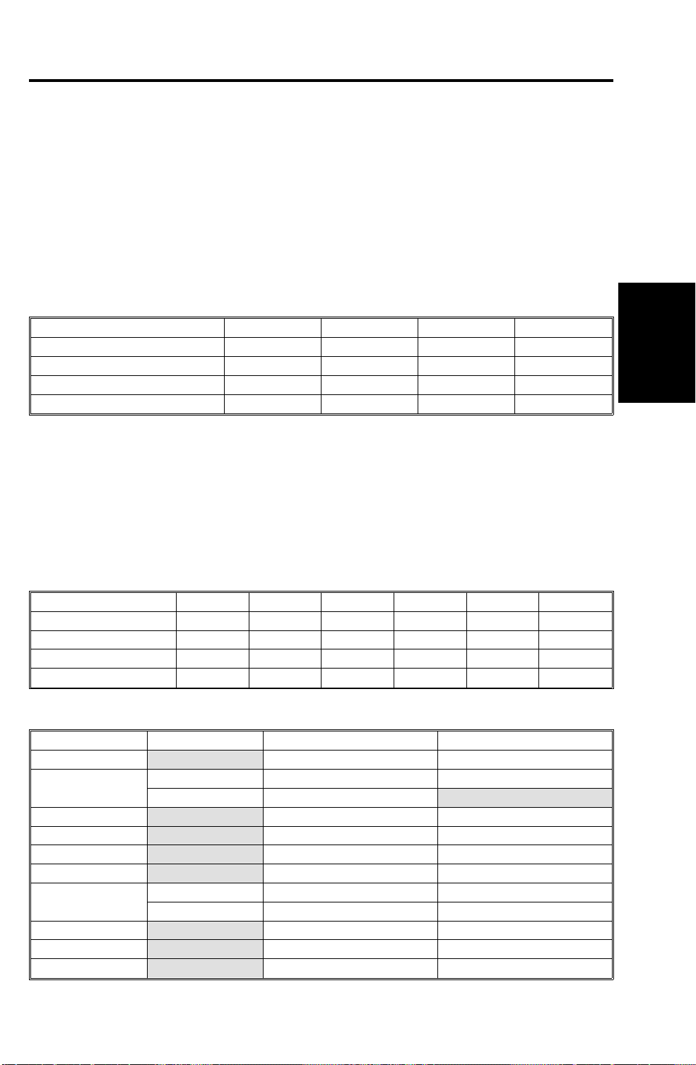
2.2 CAPABILITIES OF P ROG RAMMABLE ITEMS
The following table shows how the capabilities of each programmable item
will change after the optional funct ion upgrade card is installe d.
Item Standard With function
upgrade card
Maximum number of memory files plus
polling rx files
Maximum number of memory files 200 1000
Maximum number of destinations per file 200 200
Maximum number of destinations overall 500 2000
Maximum number of pages overall 1200 3000
Number of Quick Dials 56 56
Number of Speed Dials 100 1000
Number of Groups 9 30
Maximum number of destinations per Group 200 200
Maximum number of destinations dialed from
the ten-key pad overall
Maximum number of programs 56
(programmed in 56
Maximum number of destinations per
program
Maximum number of destinations used for all
programs
Maximum number of Auto Documents 6
(programmed in 6
Maximum number of communication records
for the TCR (Journal) stored in the memory
Maximum number of addresses specified for
features such as Authorized Reception and
Specified Cassette Selection
Maximum number of personal codes 20 50
200 1000
100 1000
Quick Dial keys)
200 200
300 2000
Quick Dial keys)
256 1000
30 50
56
(programmed in 56
Quick Dial keys)
18
(programmed in 18
keys)
Overall
Machine
Information
1-5

FEATURES July 31st, 1996
2.3 POSSIBLE COMBIN ATIONS OF OPTI ONAL IC CARDS
The following table shows which optional IC cards can be or cannot be
installed at the same time.
"Yes" in the table indicates that these two opt ion al IC cards can be installed
at the same time.
“No” in the table indicate s tha t th ese tw o optional IC cards cannot be insta lled
at the same time.
ABCDE
A: Feature Expander 2M/4M No Yes Yes Yes
B: Feature Expander 80M (HDD) No Yes Yes Yes
C: Function Upgrade Card Yes Yes Yes No
D: Page Memory Card Yes Yes Yes Yes
E: Flash/SRAM Data Copy Tool
(Service Tool)
Yes Yes No Yes
1-6
July 31st, 1996 OVERALL MACHINE CONTROL
3. OVERALL MACHINE CONTROL
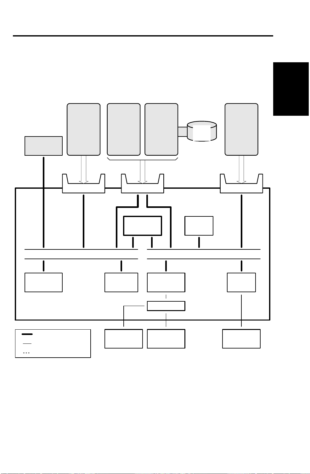
3.1 SYSTEM CONTROL
Overall
Machine
Information
G4
Flash ROM
(2MB)
Function
Upgrade
Card
Lower Left
CPU BUS
Feature
Expander
2M/4M
SRAM
(128kB)
HDD
Interface
Upper Lower Right
SCP
R144EFXL
Modem
80MB
HDD
DRAM
(2.5MB)
DMA BUS
Page
Memory
Card
VIF
FCU
Bus Interface
Parallel Interface
Serial Interface
Monitor
Speaker
Analog Circuit
1-7
NCU
BiCU
A194V500.wmf

OVERALL MACHINE CONTROL July 31st, 1996
The basic Fax Unit consists of two PCBs: an FCU and an NCU.
The FCU controls all the fax communications and fax feature s, in coo pe rat ion
with the base copier’s main board, the BiCU. The NCU switches th e analo g
line between the fax unit and the optional external telephone.
Fax Options
1. G4 unit: This allows the Fax Unit to communicate over an ISDN
(Integrated Services Digital Net work) line .
2. Function Upgrade Card: This expands the system’s SRAM capacity to
hold programmed telephon e numbe rs, com m unication records, etc.
3. Feature Expander - 2M/4M: This expands the DRAM’s capacity to hold
up to 3MB or 5MB of received data or data for transmission. Also, some
additional feat ure s beco me a vailable when the Feature E xpan de r is
installed.
4. Feature Expander - Hard Disk: This extends the image data capacity to
80MB. Also, some addition al features become available when th e Fea tu re
Expander is installed.
5. Page Memory Card (High Resolution Card): This enhances the scan and
receive resolutions to up to 400 x 400 dpi. Witho ut this card , only
’Standard’ and ’Detail’ resolutions are available for both tra nsm issio n an d
reception.
3.2 POWER DISTRIBUTIO N AND CONTROL
The FCU is supplied from the base copier’s B iCU (+24V , +12 V, -12V , and
+5VE) and PSU (+5V). Refer to the base copie r’s ser vice manual for de tails.
3.3 MEMORY B ACK-UP
The system parameters and programmed items in th e SRAM on th e FCU and
the SRAM on the Function Upgrade Card are backed up by a battery
(long-term backup), in case the the base copier’s ac switch is turned off.
Note: The data in the SRAM is not guaranteed if th e card is disco nnected
from the machine. Whenever the Function Upgrade Card needs to be
removed, follow the instructions in the software upload and download
procedures in the Service Level Functions section to avoid any data
loss.
The SAF memory DRAM on the FCU and the Feature Expander Card are
backed up by a rechargeable battery for 1-hour.
1-8

July 31st, 1996 VIDEO DATA PATH
4. VIDEO D ATA P ATH
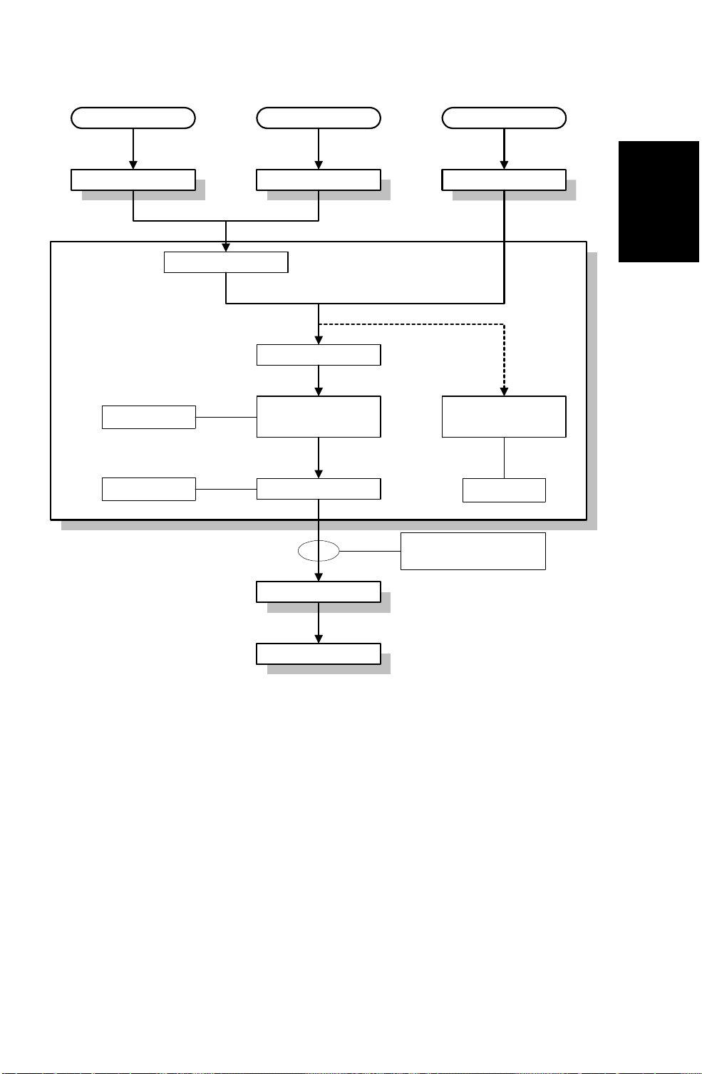
4.1 TRANSMISSION
Scanner
Sub Scan Magnification
Memory Tx
Auto Shading
Gamma Correction
MTF
Graduation Processing
Main Scan Reduction
- 400 to 200 dpi
Thresholding
Memory Tx Image Rotation Immediate Tx
DCMMR
FCU
SAF Memory
SCP
(DCR)
BiCU
Page Memory
(Rotation)
SCP
(DCMMR)
Decompression
Compression
(Main Scan Reduction)
Immediate Tx
Auto Shading
Gamma Correction
MTF
Graduation Processing
Main Scan Reduction
- 400 to 200 dpi
- Inch-mm Conversion
- A3 to B4, A3 to A4, B4 to A4
Thresholding
Page Memory
SCP
(DCR)
Compression
Overall
Machine
Information
Modem
NCU CiG4 CiG4
Analog G3 ISDN G3 ISDN G4
1-9
A194V501.wmf

VIDEO DATA PATH July 31st, 1996
Memory Transmission and Parallel Memory Transmission
The base copier’s scanner scans th e origina l at th e sele cte d reso lution in
inch format. The BiCU processes the data and transfe rs it to the FCU.
Note When scanning a fax ori gin al, the BiCU uses th e MT F and
Thresholding parame te r sett ings p rogram me d in th e scan ne r bit
switches, not the copier’s SP modes.
Then, the FCU converts the data to mm format, and compresses th e data in
MMR+raw format to store it in the SAF memory. If image rotation is possible,
the image is rotated in page memory before compression.
At the time of transmissio n, the FCU decomp resse s the store d data , th en
re-compresses and/or reduces th e data if nece ssary for tran sm ission . Eit her
the NCU or CiG4 (optional) transmit s the data to the line.
Immediate Transmission
The base copier’s scanner scans th e origina l at th e reso lut ion agre ed with
the receiving terminal. The BiCU video processes th e data and tran sfe rs it to
the FCU.
Note When scanning a fax ori gin al, the BiCU uses th e MT F and
Thresholding parame te r sett ings p rogram me d in th e scan ne r bit
switches, not the copier’s SP modes.
Then the FCU stores the data in page memory, and compresses the data for
transmission. Either the NCU or CiG4 (option al) tra nsmi t s the data to the line.
The maximum transmittable page size for immediate transmission varie s
depending on the resolution selected and the size of page memor y available .
This is becuse the scanned dat a is store d in th e pa ge me mo r y befo re
transmission, not the SAF memory. Refer to the following table for details.
Width Resolution Without optional
Page Memory card
Standard 1200 mm (47.2") 1200 mm (47.2")
A4 (210 mm)/
8.5"
B4 (256 mm)/
10.1"
A3 (297 mm)/
11"
Detail 600 mm (23.6") 1200 mm (47.2")
Fine Not usable 1200 mm (47.2")
Superfine Not usable 600 mm (23.6")
Standard 1000 mm (39.4") 1200 mm (47.2")
Detail 500 mm (19.7") 1200 mm (47.2")
Fine Not usable 1000 mm (47.2")
Superfine Not usable 500 mm (19.7")
Standard 800 mm (31.5") 1200 mm (47.2")
Detail 432 mm (17.0") 1200 mm (47.2")
Fine Not usable 800 mm (31.5")
Superfine Not usable 432 mm (17.0")
With optional Page
Memory card
1-10
July 31st, 1996 VIDEO DATA PATH
4.2 RECEPTION
Analog G3 ISDN G3 ISDN G4
NCU CiG4 CiG4
Modem
SAF Memory
FCU
Overall
Machine
Information
Decompression
Image Rotation
SCP
(DCR)
Page Memory
Data: 6 bits (64 levels)
Phase Control: 2 bits
BiCU
Printer
SCP
(DCR)
Error Check
A194V502.wmf
First, the FCU stores the data from either an analog line or an ISDN line to
the SAF memory. (The dat a goes in pa ralle l t o th e SCP , an d is checke d fo r
error lines/frames.)
The FCU then decompresses the data and transfers it to page memor y. If
image rotation is possib le, the image is rotated in page memor y. The data is
transferred to the BiCU in the 8-b it format (6-bits level/2-bits ph ase ) used by
the base copier’s laser engine for print ing.
1-11

SECTION 2
DETAILED SECTION
DESCRIPTIONS

July 31st, 1996 AUTOMATIC SERVICE CALLS
1. AUTOMATIC SERVICE CALLS
1.1 SERVICE C ALL CONDITIONS
The fax unit makes an automatic service call when an SC code, other than
the following, is informed from th e base cop ier’s BiCU.
Note The service station’s fax number ha s to be program med in
advance, for the machine to make a ser vice call.
Exceptions
Address (H) Definition Default SC code
49FB64 1st SC code - High byte (BCD) 01 192
49FB65 1st SC code - Low byte (BCD) 92
49FB66 2nd SC code - High byte (BCD) 01 193
49FB67 2nd SC code - Low byte (BCD) 93
49FB68 3rd SC code - High byte (BCD) 03 390
49FB69 3rd SC code - Low byte (BCD) 90
49FB6A 4th SC code - High byte (BCD) 03 393
49FB6B 4th SC code - Low byte (BCD) 93
49FB6C 5th SC code - High byte (BCD) 06 691
49FB6D 5th SC code - Low byte (BCD) 91
49FB6E 6th SC code - High byte (BCD) 09 980
49FB6F 6th SC code - Low byte (BCD) 80
49FB70 7th SC code - High byte (BCD) FF Not programmed
49FB71 7th SC code - Low byte (BCD) FF
49FB72 8th SC code - High byte (BCD) FF Not programmed
49FB73 8th SC code - Low byte (BCD) FF
49FB74 9th SC code - High byte (BCD) FF Not programmed
49FB75 9th SC code - Low byte (BCD) FF
49FB76 10th SC code - High byte (BCD) FF Not programmed
49FB77 10th SC code - Low byte (BCD) FF
SBU adjustment error
APS sensor error
TD sensor error 1
TD sensor error 2
BiCU/FCU
communication error
BiCU program load error
Detailed
Section
Descriptions
To add additional SC codes, program them in the blank addresses.
The fax unit cannot make an automatic service call when a Fax SC code
condition has occurred. Refer to Trouble sho ot ing f or Fax SC code details.
Manual Service Call
If the service station needs a report, the user can make a service call
manually, by setting bit 7 of User Parameter 14 (0E) to ’1’.
2-1

AUTOMATIC SERVICE CALLS July 31st, 1996
A Sample Auto Service Report Format
* * * Auto Service Report (Date and Time) * * *
Problem
S C Latest 10 copier's SC codes
J A M BJ A M 2FEED SIZE005 0708
Service Monitor Report Contents
System Parameter List Contents
Reason of the call - "SC Code" or "PM Call"
Last 4 digits of the total
print counter
Paper Size Code
Paper Feed Station
Jam Location
A194D508.wmf
Paper Size Code Table
Code Size Code Size
005 A4 sideways 038 8.5 x 11" sideways
006 A5 sideways 044 5.5 x 8.5" sideways
014 B5 sideways 160 11 x 17" lengthwise
031 Non-standard 164 8.5 x 14" lengthwise
132 A3 lengthwise 166 8.5 x 11" lengthwise
133 A4 lengthwise 172 5.5 x 8.5" lengthwise
141 B4 lengthwise
142 B5 lengthwise
159 Non-standard
2-2

July 31st, 1996 AUTOMATIC SERVICE CALLS
1.2 PERIODIC SERVICE CALL
The periodic service call notifies the service station of the machine’s
condition. The call is made at a time inter val progra mmed in the follo wing
RAM addresses:
Parameters Address (H)
Call interval: 01 through 15 month(s) (BCD)
00: Periodic Service Call Disabled
Date and time of the next call
Year: last two digits of the year (BCD) 48037A
Month: 01 through 12 (BCD) 48037B
Day: 01 through 31 (BCD) 48037C
Hour: 00 through 23 (BCD) 48037D
To change these settings after programming, change the call interval. The
machine then automatically changes the remaining parameters by referring to
the interval and the current date and time.
480379
Detailed
Section
Descriptions
1.3 PM CALL
If PM alarm is enabled by the base copie r’s SP mode and PM call is ena ble d
by system switch 01, the machine will make an automatic service call when
the base copier’s PM counter reaches the PM interval.
Cross reference
PM service call on/off: System s witch 01, bit 0
PM alarm on/off: SP mode 5-501-2 (default: enabled)
PM interval: SP mode 5-501-1 (default: 45k prints)
1.4 EFFECTIVE TERM OF SERV ICE CALLS
If a time limit for the effectiveness of service calls is programmed, the
machine stops making auto mat ic service calls after the time limit.
Program the time limit at the following addresses. This f un ctio n is disab led
when all of these addresses are 00(H).
Address (H)
Year: last two digits of the year (BCD) 480383
Month: 01 through 12 (BCD) 480384
Day: 01 through 31 (BCD) 480385
2-3

PARALLEL MEMORY TRANSMISSION July 31st, 1996
2. PARALLEL MEMORY TRANSMISSION
Using basic memory transmission, normally the machin e starts dialing after
the document has been comp let e ly scan ned. Using Parallel Memory
Transmission, the machin e starts dialing at the same tim e th e mach ine starts
scanning. If the document has mu ltip le page s, th e mach ine scans th em int o
memory and sends them while scanning continu es.
Note This function is only usable when sending an original from the
ADF.
The following table shows the differences between normal memory
transmission and parallel memory transmission.
Normal memory tx Parallel memory tx
File Reserve Report Printed, if automatic report
printout is enabled.
If the other terminal is busy Tries to resend the message
later.
If transmission failed Tries to resend the remaining
pages later.
If memory overflows during
scanning
If a document jam occurred
during scanning
How and when the scanned
message is erased from
memory
Memory threshold to start
scanning into memory
Meaning of the stamp mark Successfully stored. Successfully stored.
Batch numbering (P. x/x) Enabled Not available unless the
Including a sample of the
image on reports
Stops scanning and erases
all the scanned pages from
memory, or sends all the
scanned pages (user’s
choice).
Stops scanning and deletes
all the scanned pages from
memory.
The complete message is
erased after all the pages
have been sent.
Depends on the setting of
communication switch 0D.
Default setting - 24kB
Possible Possible
Not printed.
Continues scanning the
document into memory, and
tries to resend it later.
Tries to resend the remaining
pages later.
Stops scanning and hangs
up the communication when
memory overflow is detected.
Then erases all the scanned
pages from memory without
notifying the user.
Stops scanning and hangs
up the communication when
a document jam is detected.
Same as memory
transmission.
Depends on the setting of
system switch 10.
Default setting - 512 kB
number of pages is
programmed manually.
2-4

July 31st, 1996 PARALLEL MEMORY TRANSMISSION
In the following cases, the machine uses normal memory transmission even if
parallel memory transmission is enabled .
• Send later transmission
• Broadcasting
• Transmission of an Auto Document only
• Transfer request transmission
• When Image Rotation before Tx is enabled, and an A4 sidewa ys or
8.5 x 11" sideways original is detected
• If the other terminal is busy
• If the external telephone connecte d to the machin e is in use
• When communication switch 0A, bit 0 is set to 1, and the machine is
using memory transmission when redialing
• When remaining memo r y space is less than the thre sho ld fo r parallel
memory transmission (default = 512 kB)
• When the original is located on the expo sure glass
Detailed
Section
Descriptions
When using G4 transmission, parallel memory transmission is normally
disabled, becau se tra nsm issio n using G4 is much faster than scanning. As a
result, G4 transmission using parallel memory transmission takes about twice
as long as normal memory transmission (using an ITU-T #1 test cha rt).
If the document contains pages with complicate d im ages or it is a pho to
document using halftone, para llel memo r y transmission may be faste r tha n
normal memory transm issio n. If th e use r common l y sends this t ype of fa x
message, enable parallel memory transmission for G4 transmission by
changing system switch 11, bit 7 to 1.
Cross Reference
Parallel memory tx (G3) On/Off - User parameter 07, bit 2
Parallel memory tx (G4) On/Off - System switch 11, bit 7
Memory threshold for enabling parallel memory tx
- System switch 10, bits 0 to 7
Point of resumption of memory transmissio n upon redia ling
- Communication switch 0A, bit 0
2-5

TRANSFER BROADCASTING July 31st, 1996
3. TRANSFER BROADCASTING
This machine uses a new algorithm to identify the requester’s fax number to
send back the transf er resu lt rep ort. Previously, th e tra nsf er resu lt report did
not sometimes reach the requeste r with the old algorith m.
In a transfer broadcast ing ope rat ion , th e tra nsf er requester informs its own
fax number to the transfer station. The transfer station uses that number to
identify the request er’s fax numb er, which th e tra nsf er sta tio n must dial to
send the transfer result report ba ck to th e reque ste r.
Transmission of the tran sfe r result repo rt an d sele ctio n of the numb er to dial
depends on the following three set tin gs.
Setting Switch
Conditions required for transfer result report
transmission
Action when there is no fax number in the
programmed Quick/Speed dials which
matches the requester’s own fax number
Number of digits compared to find the
requester’s fax number from the
programmed Quick/Speed dials.
Communication switch 0B, bit 3
0: Always
1: Only if there is an error
Communication switch 0B, bit 5
0: Transfer is cancelled
1: Transfer is continued
Communication switch 0C, bits 0 to 4
(default setting = 5 digits)
The requester’s fax number f orm a t is norm a l l y as follo ws.
[ International access code ] [ Count r y cod e ] [ Are a code ] - [ Local tel. no.]
A pause (“-”) must be programmed between area code and local te l. no.
Before the machin e tra nsf ers the message, the machine compares the last
few digits of the requester’s own fax number wit h all the progra mmed
Quick/Speed Dials as shown in the following diagram. Starting from Quick
Dial 01 to the end of the Speed Dial codes. (Th e defa ult sett ing f or th e
number of digits compared is 5; see the above table.)
If the machine find s a numb er in which the compared digits ma tch tho se of
the requester’s own fax numbe r, th e mach ine choo ses th e numbe r as the
destination for sending t he repo rt back. H o wever, depen din g on the numb er
of digits compared, the machine may choose the wrong destination, as
shown in the example diagram on the next page.
Note that the machine does not compare the following:
• Pause (“-”)
• ISDN sub-address (“/aaaa”, “aaa a” is a sub-a ddress numbe r)
With a G4 transfer request, the G4 and G3 own fax numbers are informed
from the requeste r, then the machine comp are s the G4 nu mber f irst, and the
G3 number second.
2-6

July 31st, 1996 TRANSFER BROADCASTING
Example
Requester's Own Fax No.
0111201-2223456
No. of digits to compare
4
5
6
7
8
9
10
11
12
13
Result
Q01
Q05
Q05
Q05
Q08
Q08
Q08
S07
No match
No match
In this example:
Transfer Requester: USA (international dial
access code 011)
Transfer Station: UK (international dial
access code 00)
Q01
Q02
Q03
Q04
Q05
Q06
Q07
Q08
Q09
Q10
Q56
071-441-3456
020-4773456
020-4776666
00-81454771748
2223456
00-4961969063456
0569723456
201-2223456
00-31204564569
013453456
0875558888
With
Function Upgrade Card
S00
S01
S02
S03
S04
S05
S06
S07
S08
S09
S99
S999 0454771759
1223456
5413654
00-4126567878
0454771748
0634558989
07474125899
00-85226356541
00-12012223456
02212301564
6524555
00-496158756452
2223456S100
A194D501.wmf
Detailed
Section
Descriptions
In the above example:
• If the requester is within the same area, Quick Dial 05 or Quick Dial 08 is
the correct destination, depending on the required dialing method for
numbers in the same countr y or area. The mach ine select s Quick Dial 05
if it compares from 5 to 7 digits, and selects Quick Dial 08 if it compares
from 8 to 10 digits.
• If the requester is in ano ther country, Speed Dial 07 is the correct
destination. The mach ine select s this nu mber if it compa res 11 di gits. An y
setting higher than this will result in no match, due to the differen t
internationa l access cod es at the start of the number s.
• If the machine com p are s less tha n 4 digits, it select s Quick Dial 01.
• If the number of digits to compare is set to zero, the machine sends the
report to the first Quick or Speed Dial number programmed in.
Note that the resu lt can be cha nged depending on the locat ions where the
candidates are progra mmed . For exam ple , if “00 -1-2 01 2223 456” is
programmed in Quick Dial 01, the machine always selects this number for
sending back the report , e ven if th e tra nsfer request is from within the same
country.
2-7

TRANSFER BROADCASTING July 31st, 1996
When programming the mach ine to act as a Transfer Stat ion , the
combination of th e communication s witch 0C sett ing (num b er of di git s) and
the programmed locatio n of the requ est er’s fa x number ha s to be consid ere d
carefully.
If the machine can no t fin d th e de stination for the rep ort , it eit he r:
• Stops the transfer operation and prints a report locally (if bit 5 of
communication switch 0B is 0).
• Or, continues the transfer operatio n an d prin ts a result report locally after
finishing all the transfer operat ion s (if bit 5 of communicat ion s witch 0B is
1).
Cross Reference to other par am ete rs
ID code programming - Key operator mode
Use of economy transmission during a tra nsf er opera tion to end receivers
- Communication switch 0B, bit 0
Use of economy transmission during a transfer operation to next tran sfe r
stations
- Communication switch 0B, bit 1
Use of label insertion for the end receivers in a transfer operation
- Communication switch 0B, bit 2
Printout of the message when acting as a transfer stat ion
- Communication switch 0B, bit 4
2-8
July 31st, 1996 ORIGINAL SCAN PROCESS
4. ORIGINAL SCAN PROCESS
The machine scans at 400 dpi. The other end may have a different paper
size or may not be able to print at 400 dpi. The base copier’s scanner and
BiCU work together to get the required resolution and size for transmission.
4.1 MAIN SCAN DIRECTION
The base copier’s scanner al ways scans at 40 0 dpi (ma in scan direct ion ).
Then, the BiCU processes the scanned data to get the re quired resolution
and data width. This is the sam e proce ss as Redu ctio n in cop y mode .
dpi: dots per inch, dpm: dots per mm
Reduction 400 dpi 200 dpi 16 dpm 8 dpm
No reduction 100.0% 50.0% 101.5% 51.0%
A3 to B4 86.5% 43.0% 88.0% 44.0%
A3 to A4 70.5% 35.0% 71.5% 36.0%
B4 to A4 81.5% 41.0% 83.0% 41.5%
Detailed
Section
Descriptions
4.2 SUB SCAN DIRECTION
In the sub scan directio n, the base machine’s scanner changes the moto r
speed to get the required resolution. Howe ver, if the reduction rate requ ires a
faster speed than th e scan ne r mo to r’s m a xim um (37% reduction rate when
using the ADF), the scanner and the BiCU (IPU) work together to get the
required resolutio n as shown in the second table bel o w.
Reduction 400 lpi 200 lpi 100 lpm 15.4 lpm 7.7 lpm 3.85 lpm
No reduction 100.0% 50.0% 25.0%
A3 to B4 86.5% 43.2% 21.6%
A3 to A4 70.5% 35.2%
B4 to A4 81.5% 40.8% 20.4%
1
lpi: lines per inch, lpm : lines per mm
Notes Mode Reduction by Scanner Reduction by BiCU
Case 1 (35.2%) 52.8% 66.7%
Case 2 (25.0%) ADF 50.0% 50.0%
Book 25.0%
Case 3 (21.6%) 43.2% 50.0%
Case 4 (17.6%) 52.8% 33.3%
Case 5 (20.4%) 40.8% 50.0%
Case 6 (34.5%) 51.9% 66.7%
Case 7 (24.5%) ADF 48.9% 50.0%
Book 36.8% 66.7%
Case 8 (21.2%) 42.4% 50.0%
Case 9 (17.3%) 51.9% 33.3%
Case 10 (19.9%) 39.8% 50.0%
17.6%
2
97.8% 48.9% 24.5%
3
84.6% 42.3% 21.2%
4
69.0% 34.5%
5
79.7% 39.8% 19.9%
7
8
6
17.3%
9
10
2-9
PAGE SPLIT TRANSMISSION (BOOK TRANSMISSION) July 31st, 1996
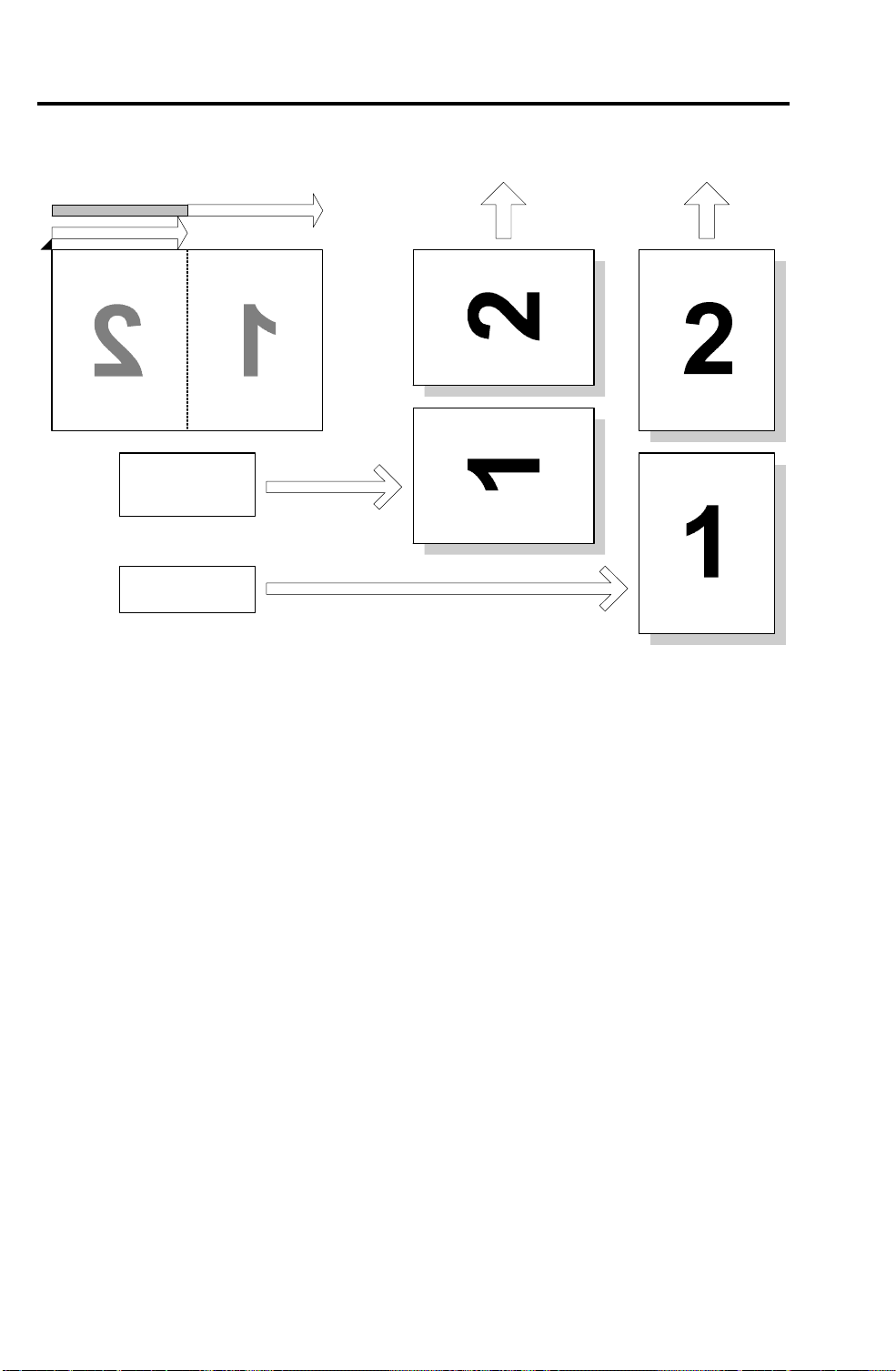
5. PAGE SPLIT TRANSMISSION (BOOK
TRANSMISSION)
2
1
Page 1Page 1
Page 2
B4
A4
8.5" x 11"
A3
11" x 17"
Page 2
A194D502.wmf
This function allows a B4, A4/8. 5 x 11", or A3/11 x 17" size book original to
be sent on two separate pages.
When this function is selecte d, the machine scans the or igin al t wice , an d
transmits the scan ne d pa ge s in the same seque nce as the pages were
scanned.
In the above example, the page with number ’2’ is sent first, and the page
with number ’1’ is sent next. To send page ’1’ first, the original should be
placed so that page ’1’ is at th e lef t.
Notes • Memory transmission is use d whene ver th is f un ctio n is
selected.
• This funct ion is onl y possible whe n sen din g a book origina l
from the exposure glass.
• If this fu nct ion is used fo r an A3 or 11 x 17" ori ginal, the
pages may be transmitted in a lengthwise direction,
depending on the setting of "Image Rotation bef ore
Transmission" (see the next page).
2-10
July 31st, 1996 IMAGE ROTATION BEFORE TRANSMISSION
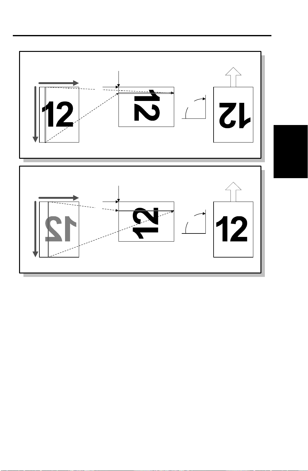
6. IMAGE ROTATION BEFORE TRANSMISSION
DF Mode
1st Pixel
1st Line
90°
(< 210mm/8.5")
Main Scan
(297mm/11")
Sub Scan
Scanned Image
Book Mode
1st Pixel
90°
Scanned ImageOriginal Transmitted Image
A194D503.wmf
(< 210mm/8.5")
Main Scan
(297mm/11")
Original Transmitted Image
Sub Scan
1st Line
This function avoids the un int en tio na l reduction of an A3 or 11" width original.
When the machine detects an A4 or 8.5 x 11" original pla ced sid e ways in the
ADF or on the exposure gla ss, th e fa x unit rotates the scanned image
clockwise by 90 degrees before tran sm ission , as sho wn ab o ve.
Detailed
Section
Descriptions
Notes • The orientations of the tran sm itt ed ima ge from th e ADF an d
from the exposure glass are different.
• Even if Paralle l Memor y Transm ission is enabled , th e
machine uses normal memory transmission to send an A4 or
8.5 x 11" sideways original.
• If the machine carries out this function while prin tin g, the
machine stops printin g until scanning is completed.
Cross Reference
Image rotation before tx on/off - Scanner switch 0F, bit 0
2-11
SMOOTHING July 31st, 1996
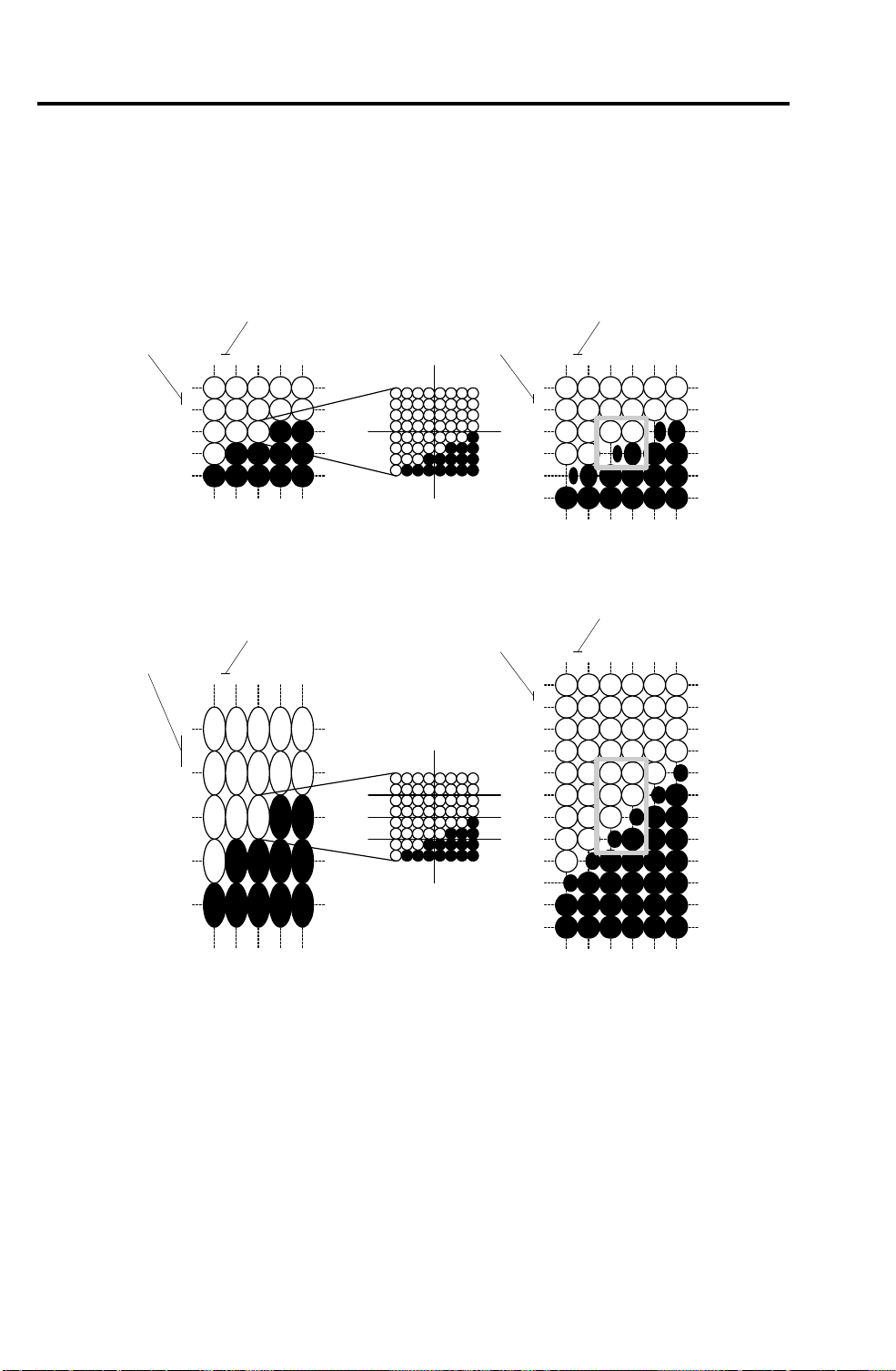
7. SMOOTHING
When the fax unit prints a recei ved fa x image, the FCU converts the data into
400 x 400 dpi, 16 x 15.4 l/mm, or 15.4 x 16 l/mm (im age rotation) resolution,
and smooths the image. The FCU then sends the smooth ed data to the
printer in the 64 gradation levels + 3 laser pu lse positions format used by the
base copier.
200 dpi
100 dpi
200 dpi
A
Received Image
200 dpi
A
Calculated Pattern
for pixel "A"
400 dpi
400 dpi
Printed Image
(Smoothed)
400 dpi
400 dpi
Received Image
Calculated Pattern
for pixel "A"
Printed Image
(Smoothed)
A194D504.wmf
Note The FCU does not smooth the received data in the following
instances:
• Halftone data is received in NSF mode
• The data is recei ved at 400 x 400 dpi or 16 x 15.4 l/mm
resolution.
• When image rotation is done, if the received data is at 200 x 100
dpi, 200 x 200 dpi, 8 x 3.85 l/mm, or 8 x 7.7 l/mm.
2-12
 Loading...