

Ricoh AFICIO 200 Service Manual AD1

IMPORTANT SAFETY NOTICES
PREVENTION OF PHYSICAL INJURY
1. Before disassembling or assembling parts of the copier and peripherals,
make sure that the copier power cord is unplugged.
2. The wall outlet should be near the copier and easily accessible.
3. Note that some components of the copier and the paper tray unit are
supplied with electrical voltage even if the main switch is turned off.
4. If any adjustment or operation check has to be made with exterior
covers off or open while the main switch is turned on, keep hands away
from electrified or mechanically driven components.
5. If the Start key is pressed before the copier completes the warm-up
period (the Start key starts blinking red and green alternatively), keep
hands away from the mechanical and the electrical components as the
copier starts making copies as soon as the warm-up period is
completed.
6. The inside and the metal parts of the fusing unit become extremely hot
while the copier is operating. Be careful to avoid touching those
components with your bare hands.
HEALTH SAFETY CONDITIONS
1. Never operate the copier without the ozone filters installed.
2. Always replace the ozone filters with the specified ones at the specified
intervals.
3. Toner and developer are non-toxic, but if you get either of them in your
eyes by accident, it may cause temporary eye discomfort. Try to remove
with eye drops or flush with water as first aid. If unsuccessful, get
medical attention.
OBSERVANCE OF ELECTRICAL SAFETY STANDARDS
1. The copier and its peripherals must be installed and maintained by a
customer service representative who has completed the training course
on those models.
2. The RAM board on the system control board has a lithium battery which
can explode if replaced incorrectly. Replace the battery only with an
identical one. The manufacturer recommends replacing the entire RAM
board. Do not recharge or burn this battery. Used batteries must be
handled in accordance with local regulations.
SAFETY AND ECOLOGICAL NOTES FOR DISPOSAL
1. Do not incinerate toner bottles or used toner. Toner dust may ignite
suddenly when exposed to an open flame.
2. Dispose of used toner, developer, and organic photoconductors in
accordance with local regulations. (These are non-toxic supplies.)
3. Dispose of replaced parts in accordance with local regulations.
4. When keeping used lithium batteries in order to dispose of them later,
do not put more than 100 batteries per sealed box. Storing larger
numbers or not sealing them apart may lead to chemical reactions and
heat build-up.
LASER SAFETY
The Center for Devices and Radiological Health (CDRH) prohibits the repair
of laser-based optical units in the field. The optical housing unit can only be
repaired in a factory or at a location with the requisite equipment. The laser
subsystem is replaceable in the field by a qualified Customer Engineer. The
laser chassis is not repairable in the field. Customer engineers are therefore
directed to return all chassis and laser subsystems to the factory or service
depot when replacement of the optical subsystem is required.
WARNING
Use of controls, or adjustment, or performance of procedures other than
those specified in this manual may result in hazardous radiation exposure.
WARNING FOR LASER UNIT
WARNING: Turn off the main switch before attempting any of the
procedures in the Laser Unit section. Laser beams can
seriously damage your eyes.
CAUTION MARKING:
DANGER
>PS<
DANGER
INVISIBLE LASER RADIATION
WHEN OPEN.
!
AVOID DIRECT EXPOSURE TO
BEAM.
INVISIBLE LASER RADIATION
WHEN DISCONNECT OPTICAL
FIBER CABLE.
!
AVOID DIRECT EXPOSURE TO
BEAM.
>PS<
>PS<

SECTION 1
OVERALL MACHINE
INFORMATION

1 August 1996 SPECIFICATIONS
1. SPECIFICATIONS
Configuration: Desktop
Copy Process: Dry electrostatic transfer system
Originals: Sheet/Book
Original Size: Maximum A3/11" x 17"
Copy Paper Size: Maximum
A3/11" x 17"
Minimum
A5/8
A6/5
1/2
1/2
" x 5
" x 8
1/2
" sideways (Paper tray)
1/2
" lengthwise (By-pass)
Copy Paper Weight: Paper tray:
2
60 ~ 90 g/m
, 16 ~ 24 lb
By-pass:
2
60 ~ 157 g/m
, 16 ~ 42 lb
Reproduction Ratios: 5 Enlargement and 7 Reduction
A4/A3 Version LT/DLT Version
400%
200%
Enlargement
Full size 100% 100%
Reduction
141%
122%
115%
93%
87%
82%
71%
65%
50%
25%
400%
200%
155%
129%
121%
93%
85%
77%
74%
65%
50%
25%
Zoom: 25% to 400% in 1% steps
Power Source: 120V/60 Hz:
More than 12 A (for North America)
220V ~ 240V/50 Hz:
More than 7 A (for Europe)
220V ~ 240V/60 Hz:
More than 7 A (for Asia)
1-1
SPECIFICATIONS 1 August 1996
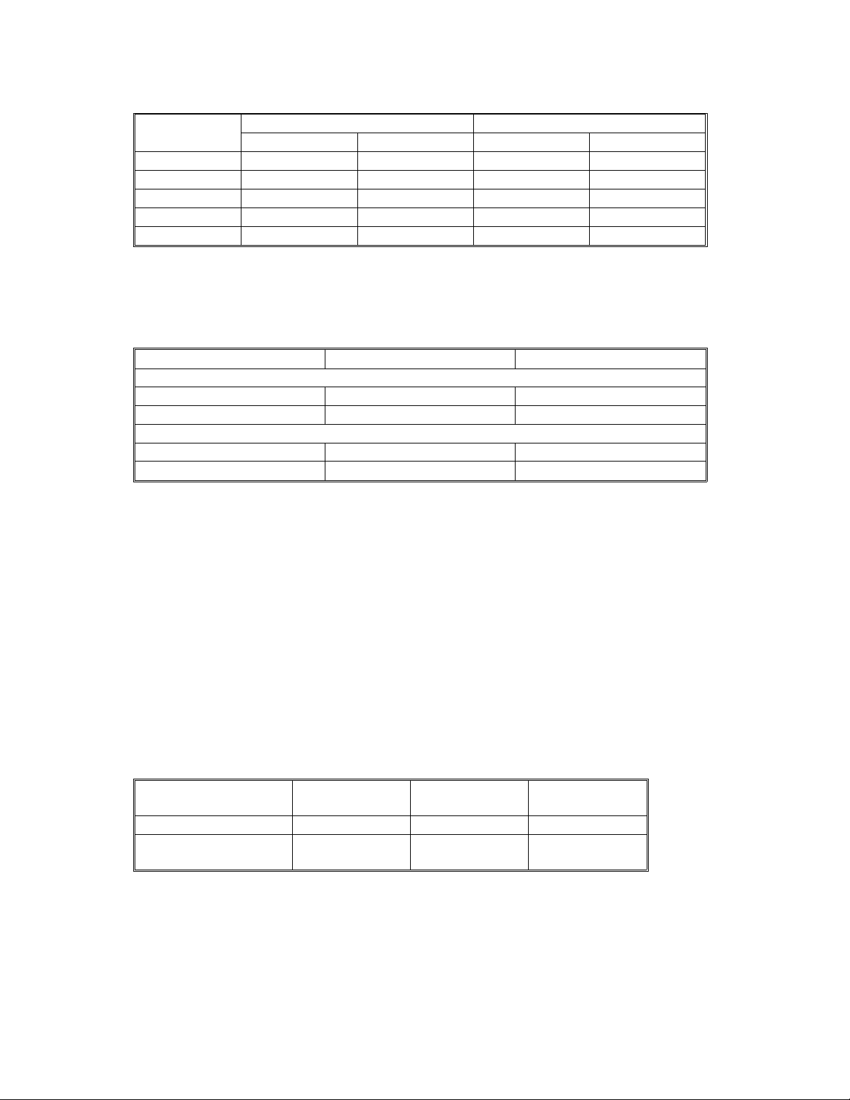
Power Consumption:
Mainframe Onl y Full System
120V 220V ~ 240V 120V 220V ~ 240V
Maximum Less than 1.1 kW Less than 850 W Less than 1.2 kW Less than 1 kW
Copying Approx. 470 W Approx. 500 W Approx. 500 W Approx. 530 W
Warm-up Approx. 1.0 kW Approx. 750 W Approx. 1.0 kW Approx. 750 W
Stand-by Approx. 130 W Approx. 130 W Approx. 140 W Approx. 140 W
Auto Shut Off Approx. 2.0 W Approx. 2.2 W Approx. 2.2 W Approx. 2.4 W
NOTE:
Full System: Mainframe + ADF + Paper Tray Unit + Duplex Tray +
1-bin Sorter
Noise Emission:
Mainframe Onl y Full System
1. Sound Power Level
Copyin g 61.5 dB(A) 64.5 dB(A)
Stand-by 30.0 dB(A) 30.0 dB(A)
2. Sound Pressure Level at the Operator Position
Copyin g 47.5 dB(A) 52.0 dB(A)
Stand-by 17.5 dB(A) 17.5 dB(A)
NOTE:
The above measurements were made in accordance with ISO 7779.
Full System: Mainframe + ADF + Paper Tray Unit + Duplex Tray +
1-bin Sorter
Dimensions (W x D x H): 550 x 580 x 652 mm (21.7" x 22.9" x 25.7")
Measurement Conditions
1) With by-pass feed table closed
2) Without the optional paper tray unit
3) Without the ADF
Weight: Less than 57 kg (126 lb)
Copying Speed in Multicopy mode (copies/minute):
A4 sideways/
11" x 8
No optional memory 15 9 10
With 4MB or 8MB
optional memory
Warm-up Time
"
1/2
20 11 12
Less than 30 seconds (20°C, 68°F): 115V
A3/11" x 17" B4/8
1/2
machine
Less then 35 seconds (20°C, 68°F): 230V
machine
1-2
" x 14"

1 August 1996 SPECIFICATIONS
First Copy Time: Less than 9.8 s (from 1st paper tray to face down
copy tray)
Less than 8.8 s (from 1st paper tray to face up
copy tray)
Copy Number Input: Ten-key pad, 1 to 99 (count up or count down)
Manual Image Density: 7 steps
Automatic Reset: 60 s is the standard setting; it can be changed
with a UP mode.
Auto Shut Off 15 min. is the standard setting; it can be
changed with a UP mode.
Copy Paper Capacity: Paper Tray: 250 sheets
Optional Paper Tray Unit: 500 sheets x 2
Bypass: 100 sheets (A4, B5, A5, B6, 8.5 x 11",
5.5 x 8.5")
10 sheets (A3, B4, 11 x 17", 8 x 13")
1 sheet (non-standard sizes)
Toner Replenishment: Cartridge exchange (216 g/cartridge)
Toner Yield: 8 k copies (A4 sideways, 6% full black, 1 to 1
copying, ADS mode)
•
Optional Equipment:
Platen cover
•
Auto document feeder
•
Paper tray unit with two paper trays
•
1-bin sorter
•
Duplex unit
•
Key counter
•
Tray heater
•
Optical anti-condensation heater
Copy Tray Capacity Face down mode: 500 sheets
Face up mode: 100 sheets
Memory Capacity:
Standard (4 MB) Optional 4 MB Optional 8 MB
Multi duplex copy X O O
Sort, Rotate Sort A4, LT O O O
B4, LG X O O
A3, DLT X O O
Number of pages A4 6% 35 99 99
ITU-T#4154575
X: Not AvailableO: Available
1-3
MACHINE CONFIGURATION 1 August 1996
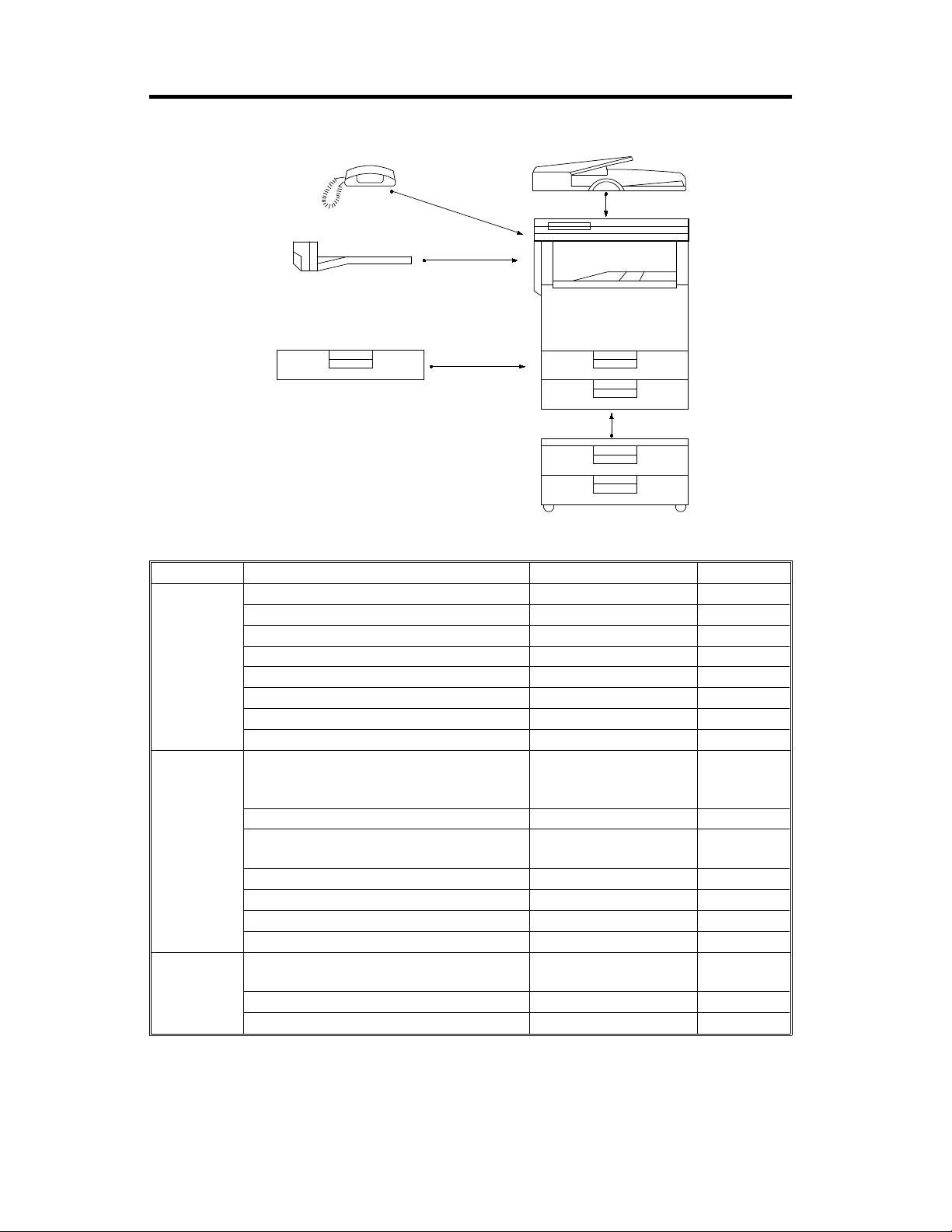
2. MACHINE CONFIGURATION
A
D
B
E
C
F
A193V501.wmf
Version Item Machine Code No.
Copier Copier A193 E
ADF (Option) A628 D
Paper Tray Unit (Opt ion) G697 F
Duplex Unit (Opt i on) G694 C
1-bin Sorter (Option) A629 B
Platen Cover (Option) A645
Memory 4MB (Opti on) A642-01
Memory 8MB (Opti on) A642-02
Fax Fax Controller (Option) A639-01 (115V),
-02(230V),
-03(F rance), -04 (TWN)
Telephone (Opt i on) H160 A
ISDN (Option) A644-01(115V),
-02(230V)
HDD (Option) A641
Memory Card (Option) H130-54
Function Card (Option) H130- 52
Page Memory (Option) A640
Printer Printer Controlle r (O pt i on) A643-00 (1 15V) ,
-01(230V)
PS Option (Option) A643-02
HDD (Option) A643-03
1-4
1 August 1996 PAPER PATH
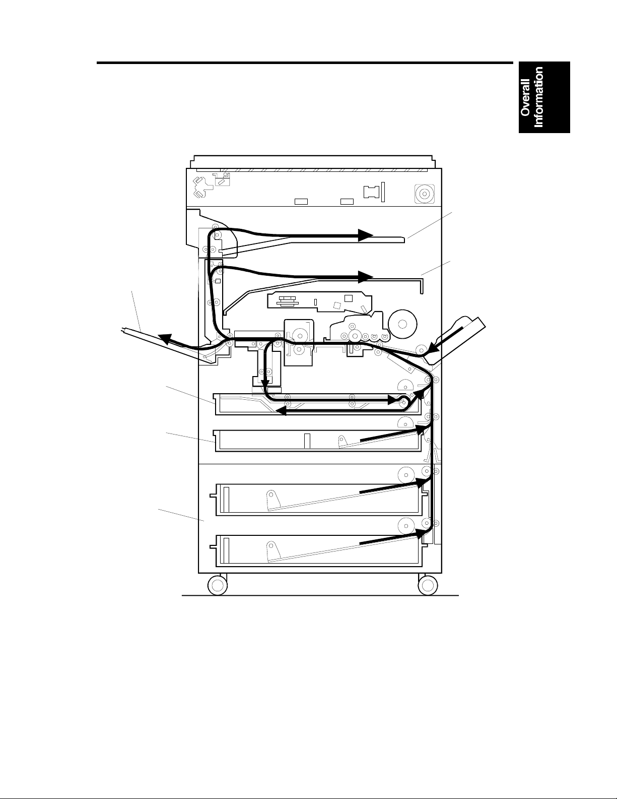
3. PAPER PATH
Optional
1-bin
Sorter
Face
Face Up
Tray
Down Tray
Optional
Duplex
Tray
Paper
Tray
Optional
Paper
Tray Unit
A193V005.wmf
1-5
MECHANICAL COMPONENT LAYOUT 1 August 1996
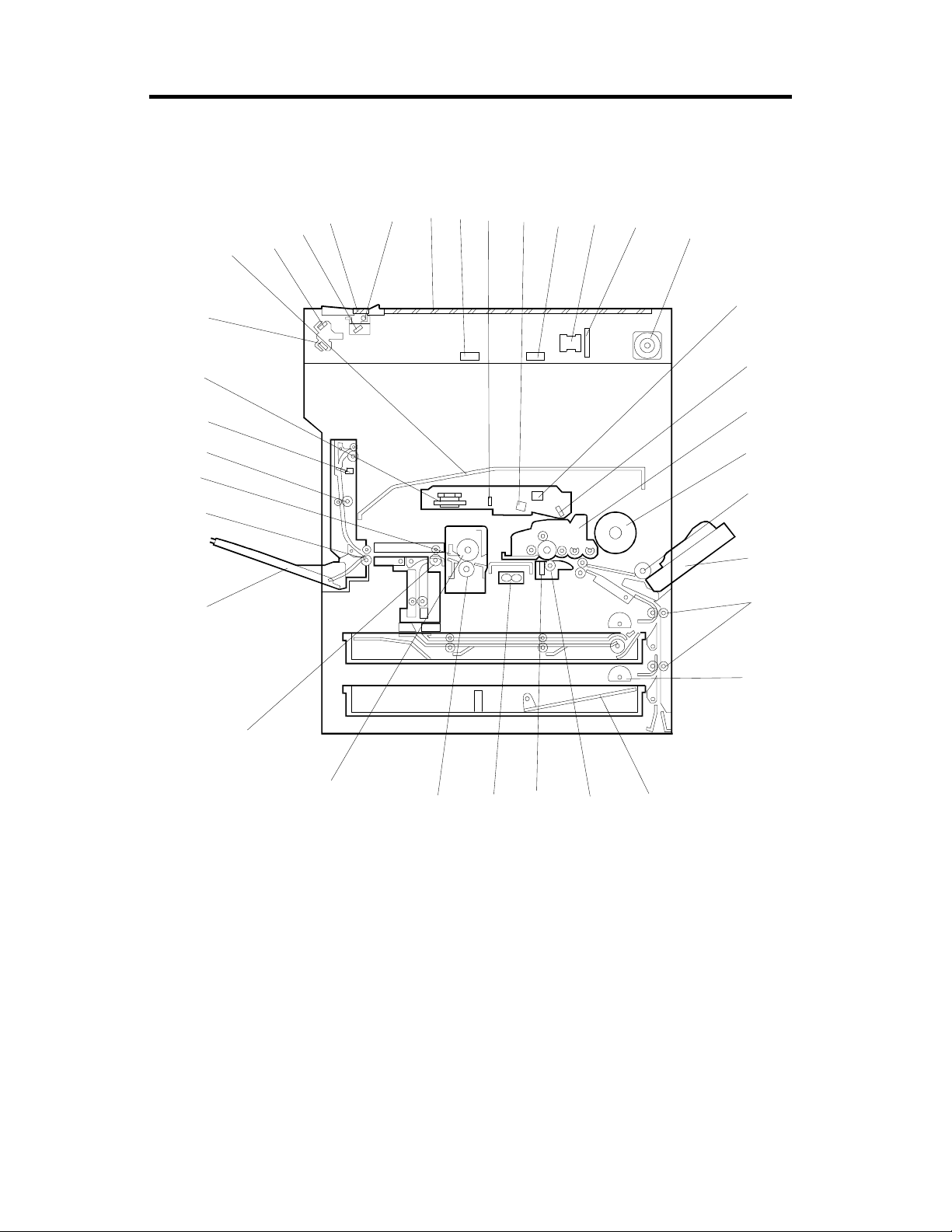
4. MECHANICAL COMPONENT LAYOUT
6
7
8
10
9
11
12
13
34
35
5
3
2
4
1
33
32
31
30
29
28
27
26
25
24
23
22
14
15
16
17
18
19
20
A193V502.wmf
21
1-6

1 August 1996 MECHANICAL COMPONENT LAYOUT
1. 2nd Mirror
2. 1st Mirror
3. DF Exposure Glass
4. Xenon Lamp
5. Exposure Glass
6. Original Width Sensors
7. 1st Mirror
8. Barrel Toroidal Lens (BTL)
9. Original Length Sensors
10. Lens
11. SBU Board
12. Scanner Motor
13. F-theta Mirror
14. 2nd Mirror (Laser Unit)
15. PCU
22. Transfer Roller
23. Separation Brush
24. Transport Vacuum Fan
25. Pressure Roller
26. Hot Roller
27. Fusing Exit Roller
28. Left Vertical Door/Face Up
Tray
29. Junction Gate
30. Hot Roller Strippers
31. Left Vertical Roller
32. Lower Exit Sensor
33. Polygonal Mirror Motor
34. 3rd Mirror
35. Face Down Tray
16. Toner Bottle
17. By-pass Feed Roller
18. By-pass Table
19. Relay Rollers
20. Paper Feed Rollers
21. Bottom Plate
1-7

ELECTRICAL COMPONENT DESCRIPTIONS 1 August 1996
5. ELECTRICAL COMPONENT DESCRIPTIONS
Refer to the electrical component layout and the point-to-point diagram on the
waterproof paper in the pocket for the locations of these components.
Symbol
Printed Circuit Boards
PCB1 54
PCB2 50 Lamp Stabilizer Provides dc power for the exposure lamp.
PCB3 58
PCB4 61 LD Unit Controls the laser diode.
PCB5 62
PCB6 51
PCB7 55 IOCSS Co nt rols the mechanical par t s of the p rinter.
PCB8 52
PCB9 53
Motors
M1 45 Main Drives the m ai n body components.
M2 36
M3 47
M4 49 Pol ygonal Mirror Turns the polygonal mirror.
M5 37
M6 35 Exhaust Fan Removes heat from around the fusing unit.
Index
No.
Description Note
High Voltage Supply
Board
PSU Provides dc powe r to the system and ac
Operation Pan e l Controls th e to uch panel displa y and LED
SBU Contains the CCD, and outputs a video
BICU Cont ro l s al l copier functions b ot h di r ect l y or
MSU Compressed the imag e dat a, stores the
Scanner Drive Drives the 1st and 2nd scanners (dc stepper
Transport Vac uum
Fan
Toner Supply Rotates the toner bottle to supply toner to
Supplies high voltage to the drum charge
roller, devel opment roller , tra n sf er roller, and
discharge br ush.
power to the fusing lamp.
matrix, and monitors the key matrix.
signal to the BICU b oar d.
through othe r co ntrol boards.
data, and appl i es the image editing.
motor).
Aids paper transportation from the transfer
roller to the fusing u n it.
the toner supply unit.
Sensors
S1 33 Up per Exi t Detects misf eeds.
S2 31 Low er Exi t Detects misfeeds.
S3 28 Left Vert i cal D oor Cuts the +5 and +24 Vdc power lines.
S4 27
S5 17
S6 10 PCU Detects when a new PCU is installed.
S7 29 Fusi ng Exit Detects misf eeds.
Left Door Detects whether the left door is open or
closed.
Relay Detects the leading edge of paper from the
paper tray and d upl ex unit to determ ine the
stop timing of the paper feed clutch and
duplex feed motor. Also detects misfeeds.
1-8
1 August 1996 ELECTRICAL COMPONENT DESCRIPTIONS
Symbol
S8 9
S9 14
S10 15
S11 16
Index
No.
Description Note
Charge Roller H.P Informs the CPU when the dru m charge
roller is at home position.
Upper Tray Paper
End
Lower Tray Paper
End
By-pass Feed Paper
End
Informs the CPU w hen the upper paper tr ay
runs out of pape r.
Informs the CPU when the lower paper tray
runs out of pape r.
Informs the CPU w hen there is no paper in
the by-pass tray.
Registrati on Detect s th e l eading edge of the cop y paper
S12 12
to determin e th e stop timing of the pap er
feed clutch, and detects misfe eds.
S13 11
By-pass Feed Paper
Width
Detects the wi dt h of the paper in the by-pass
feed table.
S14 59 Humidity Monitors the humidity around the PCU.
S15 4
S16 5
S17 6
Original Width Detects the width of the original. This is one
of the APS (Auto Paper Select) sen sors.
Original Length-1 Detects the length of the or i gi nal. This is one
of the APS (Auto Paper Select) sen sors.
Original Length-2 Detects the length of the or i gi nal. This is one
of the APS (Auto Paper Select) sen sors.
Platen Cover Informs the CPU w het her the platen cover is
S18 3
up or down (related to APS/ARE functions).
ARE: Auto Reduce and Enlarge
S19 1
S20 23
Scanner H.P. Informs the CPU when the 1st and 2nd
scanners are at th e hom e position.
Toner Densi t y (TD) Detects the amount of toner inside the
development uni t .
Switches
SW1 21 AC Supplies power to the copier.
SW2 32 Ma i n Supplies powe r to operate the machine.
SW3 13 Right Vertical Guide Cuts the +5 and +24 Vdc power lines.
SW4 20
SW5 19
Upper Paper Size Determin es w hat size of paper is in t he
upper paper tray.
Lower Paper Size Determines what size of paper is in the lower
paper tray.
Front Door Safety Cuts the +5VLD and +24V dc power lines
SW6 26
and detects whet her the front cove r is open
or not.
Magnetic Clutches
MC1 46
Charge Roller Contact Controls the touch and release movem ent of
the drum ch arge rol l er.
MC2 42 Upper R el ay Drives the upper rel ay rollers.
MC3 43 Lower Relay Drives the lower relay rollers.
MC4 40
By-pass Feed Starts paper feed from the by -pass feed
table.
MC5 41 Upper Paper Feed Starts paper feed from the upper paper tray.
1-9

ELECTRICAL COMPONENT DESCRIPTIONS 1 August 1996
Symbol
MC6 44 Lower Paper Feed Starts paper feed from the lower paper tray.
MC7 39 Registration Drives the registration rollers.
MC8 38
Solenoids
SOL1 48
Lamps
L1 60
L2 2 Scanner Applies light to the origin al fo r exposure.
L3 8 Fusing Provides heat to the hot roller.
Heaters
H1 18
H2 34
Index
No.
Description Note
Development Dri ves the development roller.
Junction Gate Moves the junction gate to direct copies to
the face up or face down copy tray.
Quenching Neutralizes any charge remai ning on the
drum surfa ce af t er cl eaning.
Tray (option) Turns on when the main sw i tc h i s of f to keep
paper in the pa per tray dry. Tray heaters are
also available for the optional paper feed unit.
Anti-condensation
(option)
Turns on when t he main switch is of f to
prevent moisture from accumulating.
Thermistors
TH1 24
TH2 22 Fusi ng Monitors the temper at ur e of the hot roller.
Thermofuses
TF1 7
Counters
CO1 2 5
CO2 ---
Others
LSD1 30
NF 56
CB 57
Charge Roller Monitors the tem perature of the drum charge
roller.
Fusing Provides back-up overheat pr ot ection in the
fusing unit.
Total Keeps track of the total number of copies
made.
Key
(option)
Laser
Synchronization
Detector
Noise Filter
(230V machine only)
Circuit Breaker
(230V machine only)
Used for contro l of authorized use . Th e
copier will not operate until it is installed.
Detects the laser beam at the sta rt of the
main scan.
Removes electrical noise from the AC input
line.
Guards against voltage surg es i n t he AC
input line.
1-10
1 August 1996 DRIVE LAYOUT
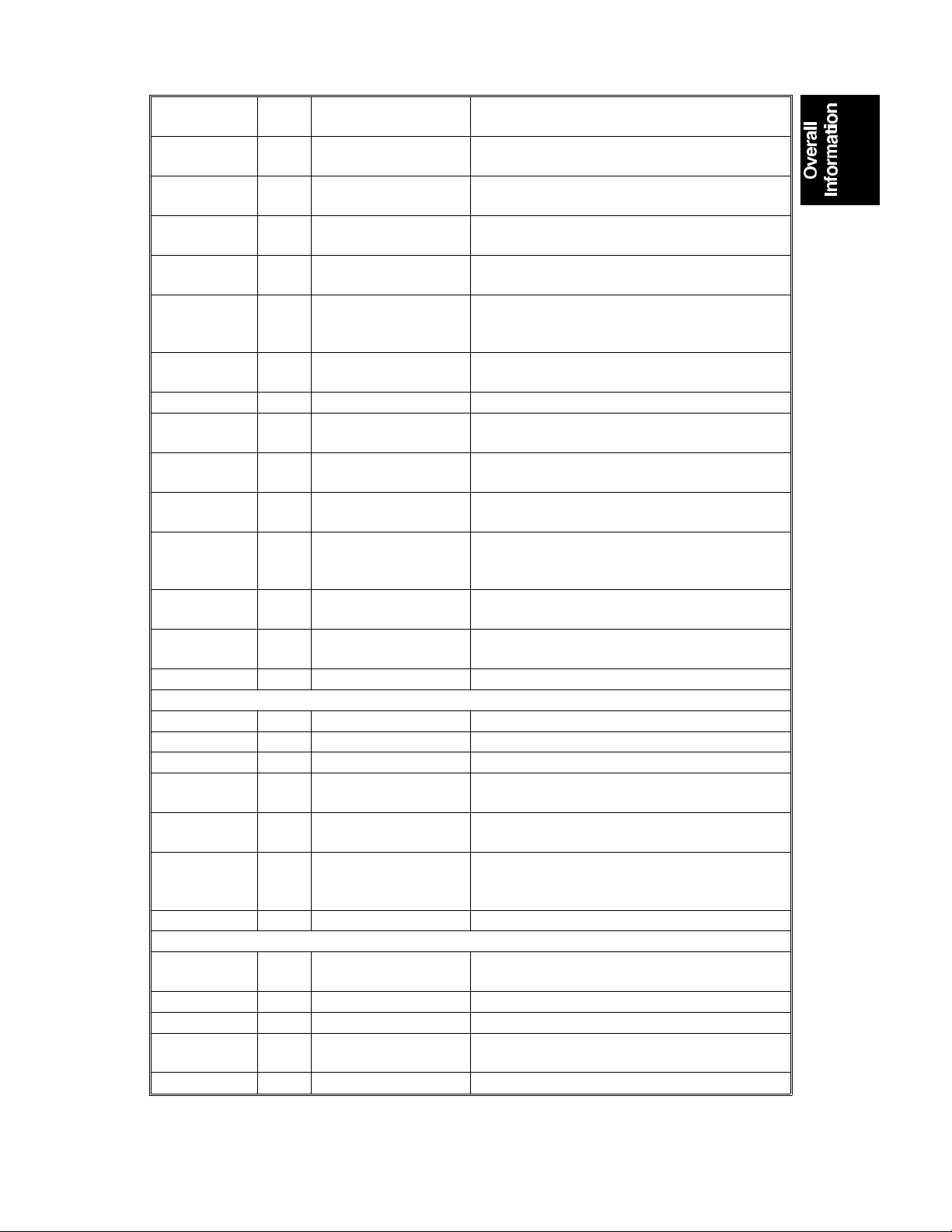
6. DRIVE LAYOUT
1
2
3
10
9
8
7
4
A193V503.wmf
6
1. Scanner Drive Motor
2. Development Clutch
3. Charge Roller Contact
4. Main Motor
5. Registration Clutch
5
6. Lower Paper Feed Clutch
7. Lower Relay Clutch
8. Upper Relay Clutch
9. Upper Paper Feed Clutch
10. By-pass Feed Clutch
1-11
COPY PROCESS 1 August 1996
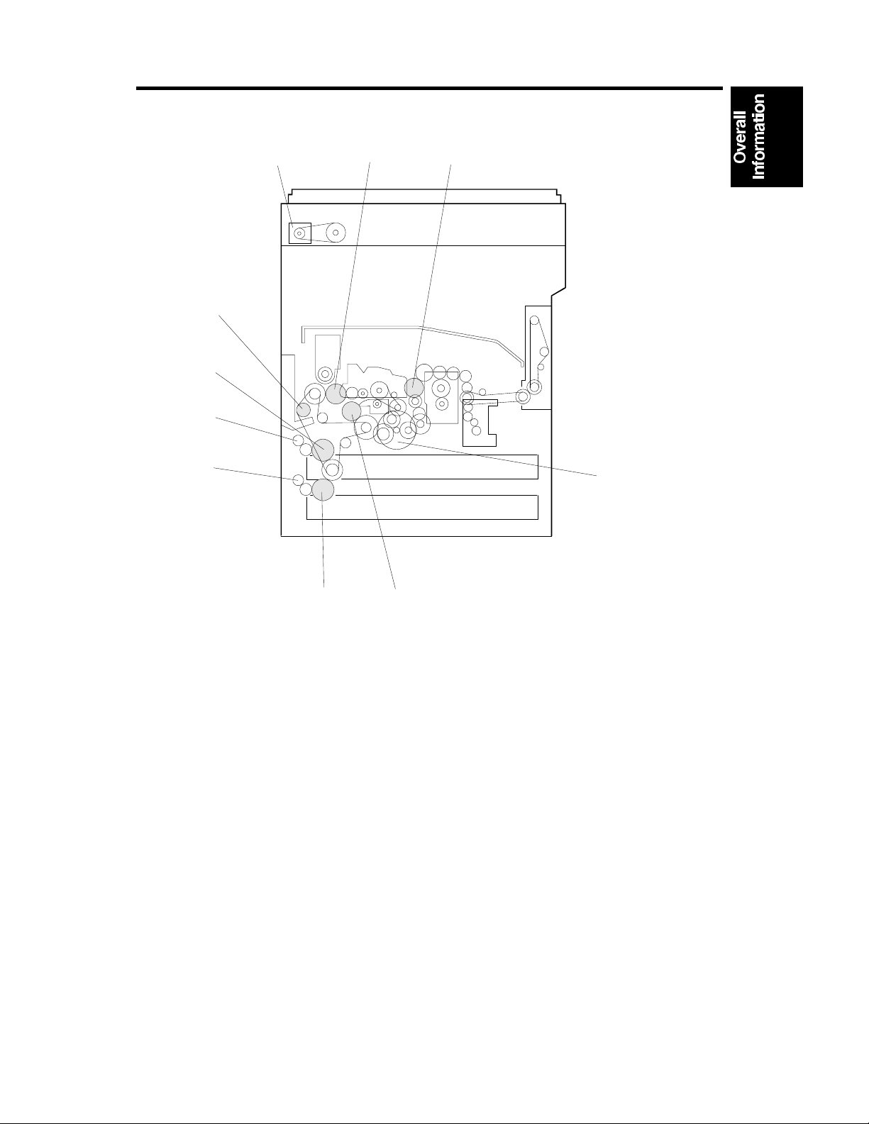
7. COPY PROCESS
7.1 OVERVIEW
Pow er
Pack
-90 V
-1750 V
8
7
1
2
3
-140 V
-900 V
4
-600 V
6
5
A193V505.wmf
+2 kV
1-12
+15 µA
Pow e r Pa ck
A193V506.wmf

1 August 1996 COPY PROCESS
1. EXPOSURE
A xenon lamp exposes the original. Light reflected from the original passes to
the CCD, where it is converted into an analog data signal. This data is
converted to a digital signal, processed, and stored in the memory. At the
time of printing, the data is retrieved and sent to the laser diode. For
multi-copy runs, the original is scanned once only and stored to the memory.
2. DRUM CHARGE
In the dark, the charge roller gives a negative charge to the organic
photo-conductive (OPC) drum. The charge remains on the surface of the
drum because the OPC layer has a high electrical resistance in the dark.
3. LASER EXPOSURE
The processed data scanned from the original is retrieved from the memory
and transferred to the drum by a laser beam, which forms an electrical latent
image on the drum surface. The amount of charge remaining as a latent
image on the drum depends on the laser beam intensity, which is controlled
by the BICU board.
4. DEVELOPMENT
The magnetic developer brush on the development rollers comes in contact
with the latent image on the drum surface. Toner particles are
electrostatically attracted to the areas of the drum surface where the laser
reduced the negative charge on the drum.
5. IMAGE TRANSFER
Paper is fed to the area between the drum surface and the transfer roller at
the proper time for aligning the copy paper and the developed image on the
drum surface. Then, the transfer roller applies a high positive charge to the
reverse side of paper. This positive charge produces an electrical force which
pulls the toner particles from the drum surface on to the paper. At the same
time, the paper is electrically attracted to the transfer roller.
6. PAPER SEPARATION
Paper separates from the drum as a result of the electrical attraction between
the paper and the transfer roller. The discharge brush helps separate the
paper from the drum.
7. CLEANING
The cleaning blade removes any toner remaining on the drum surface after
the image is transferred to the paper.
8. QUENCHING
The light from the quenching lamp electrically neutralizes the charge on the
drum surface.
1-13
BOARD STRUCTURE 1 August 1996
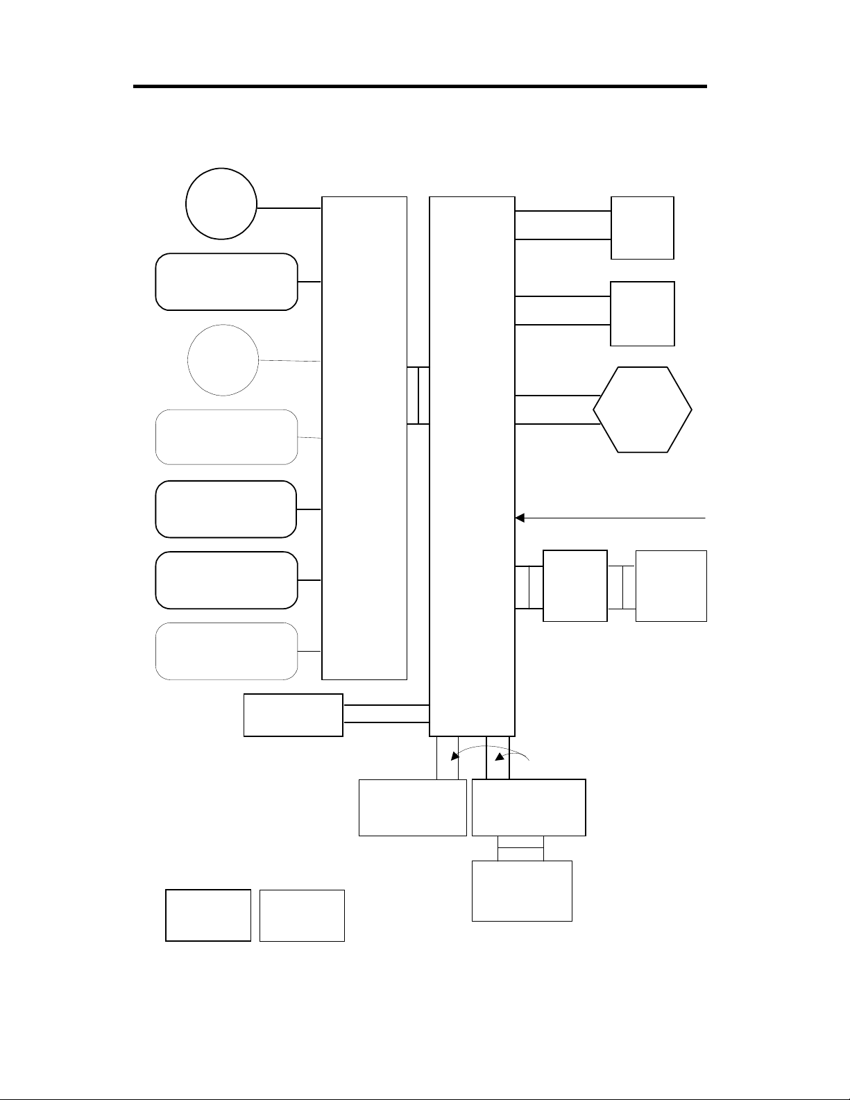
8. BOARD STRUCTURE
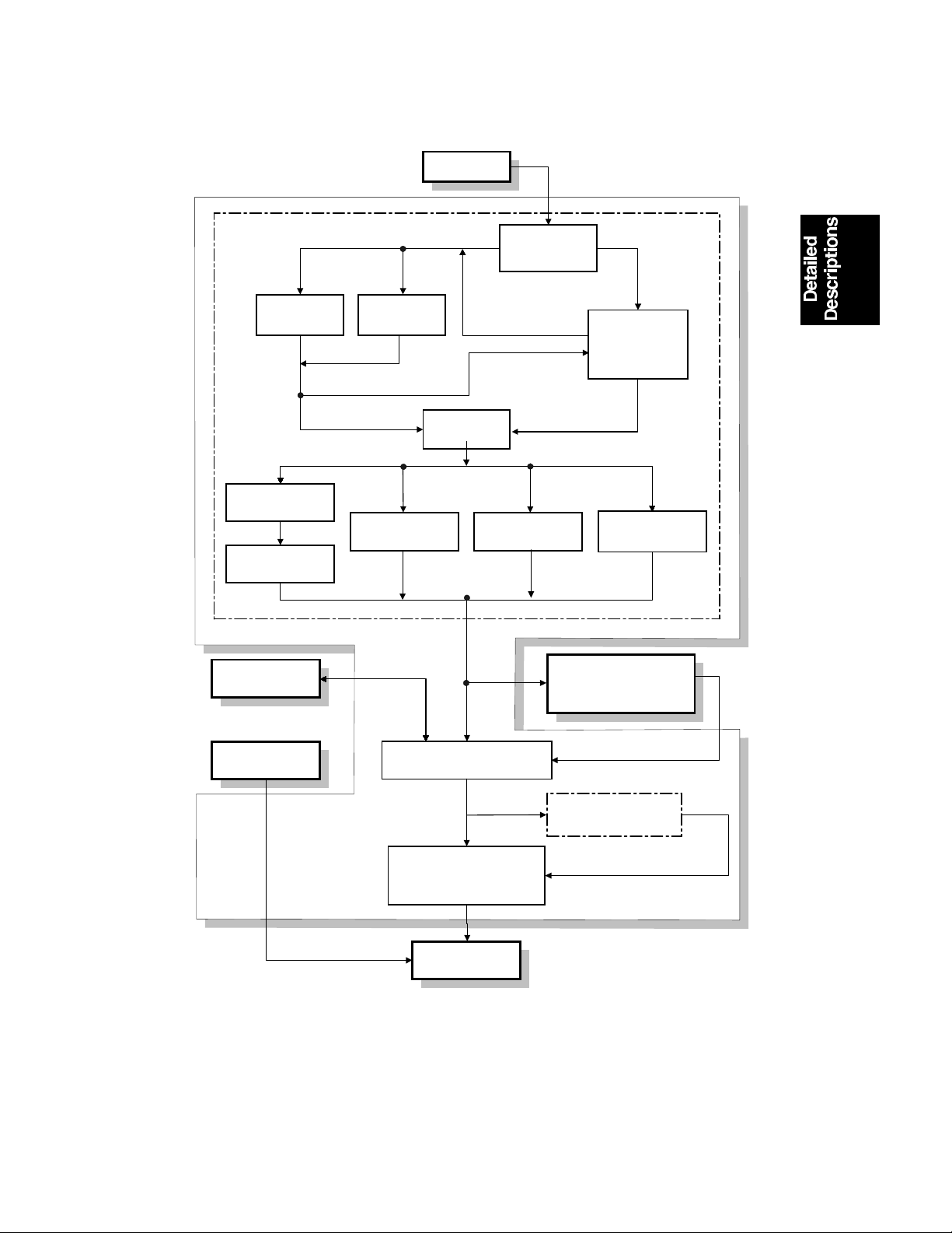
8.1 OVERVIEW
Scanner
Motor
Flat Cable
SBU
Scanner
Laser Printer
Sensors, Solenoids,
Motors, Clutches
High Voltage Supply
Peripheral
Motors, Solenoids,
Sensors
Motor
DF
Sensors,
DF
Solenoids
Sensors,
Clutches
Harness
BICUIOCSS
Harness
LD Unit
Polygon
Mirror
Motor
Laser Synchronization
Signal = Optical Cable
MSU
Additional
Memory
Operation
Panel
Standard Option
Harness
Flat Cable
Fax Controller Mother Board
Printer
Controller
A193V504.wmf
1-14

1 August 1996 BOARD STRUCTURE
8.2 DESCRIPTION
1. BICU (Base Engine and Image Control Unit)
This is the main board. It controls the following functions:
•
Engine sequence
•
Scanner, laser printer engine
•
Timing control for peripherals
•
Image processing, video control
•
Operation control
•
Corresponding application boards
•
Machine control, system control
2. IOCSS (I/O and Customer Support System Unit)
The IOCSS board handles the following functions:
•
Drive control for the sensors, motors, solenoids of the printer and scanner
•
PWM control for the high voltage control board
•
Serial interfaces with peripherals
•
Circuit for fusing control
3. SBU (Sensor Board Unit)
The SBU deals with the analog signals from the CCD and converts them into
digital signals.
4. MSU (Memory Super-charger Unit)
The MSU stores and compresses the image data. It also does image editing
on the data if requested by the user. An extra 4 MB or 8 MB of memory can
be added (see below).
5. Additional Memory (Option)
This is an additional image memory board for the MSU.
6. LD Unit
This is the laser diode drive circuit board.
7. Mother Board
This is the printer control board as well as the BICU interface board. It
receives the signals from the printer control board and sends signals to the
printer control board.
1-15

SECTION 2
DETAILED SECTION
DESCRIPTIONS
1 August 1996 SCANNING
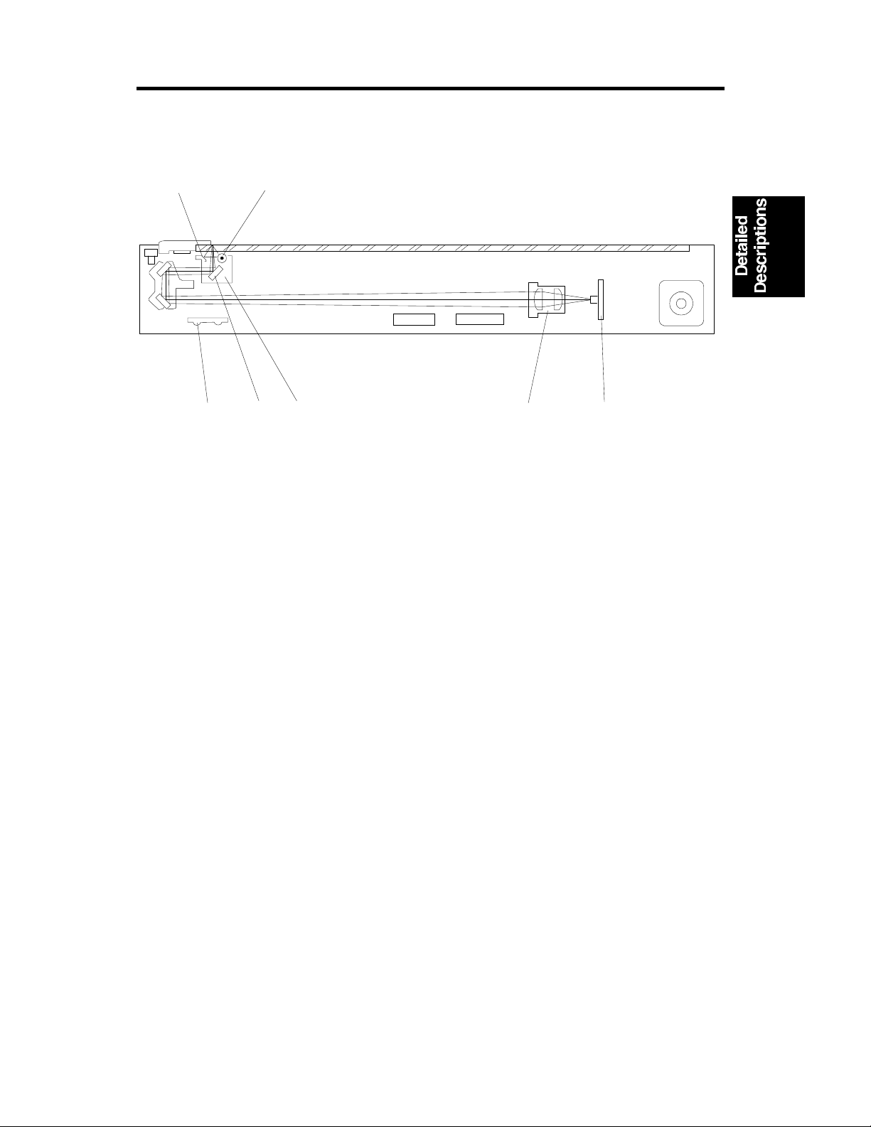
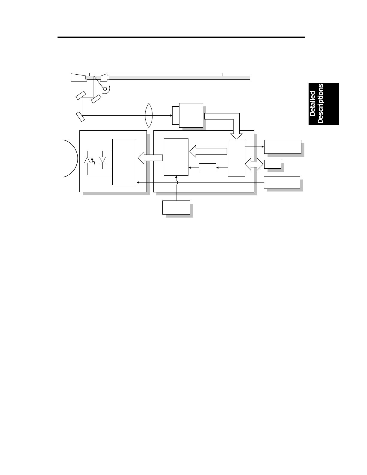
1. SCANNING
1.1 OVERVIEW
[E]
[G]
[A]
A193D001.wmf
[D][F]
[C]
[B]
The original is illuminated by the exposure lamp (a xenon lamp in this model)
[A]. The image is reflected onto a CCD (charge coupled device) [B] via the
1st, 2nd, 3rd mirrors, and lens [C].
The 1st scanner [D] consists of the exposure lamp, a reflector [E], and the 1st
mirror [F].
The exposure lamp is energized by a dc supply to avoid uneven light
intensity as the 1st scanner moves in the sub scan direction. The entire
exposure lamp surface is frosted to ensure even exposure in the main scan
direction.
The light reflected by the reflector is of almost equal intensity, to reduce
shadows on pasted originals.
An optics anti-condensation heater [G] is available as an option. It can be
installed on the left side of the inner cover. It turns on whenever the power
cord is plugged in.
2-1
SCANNING 1 August 1996
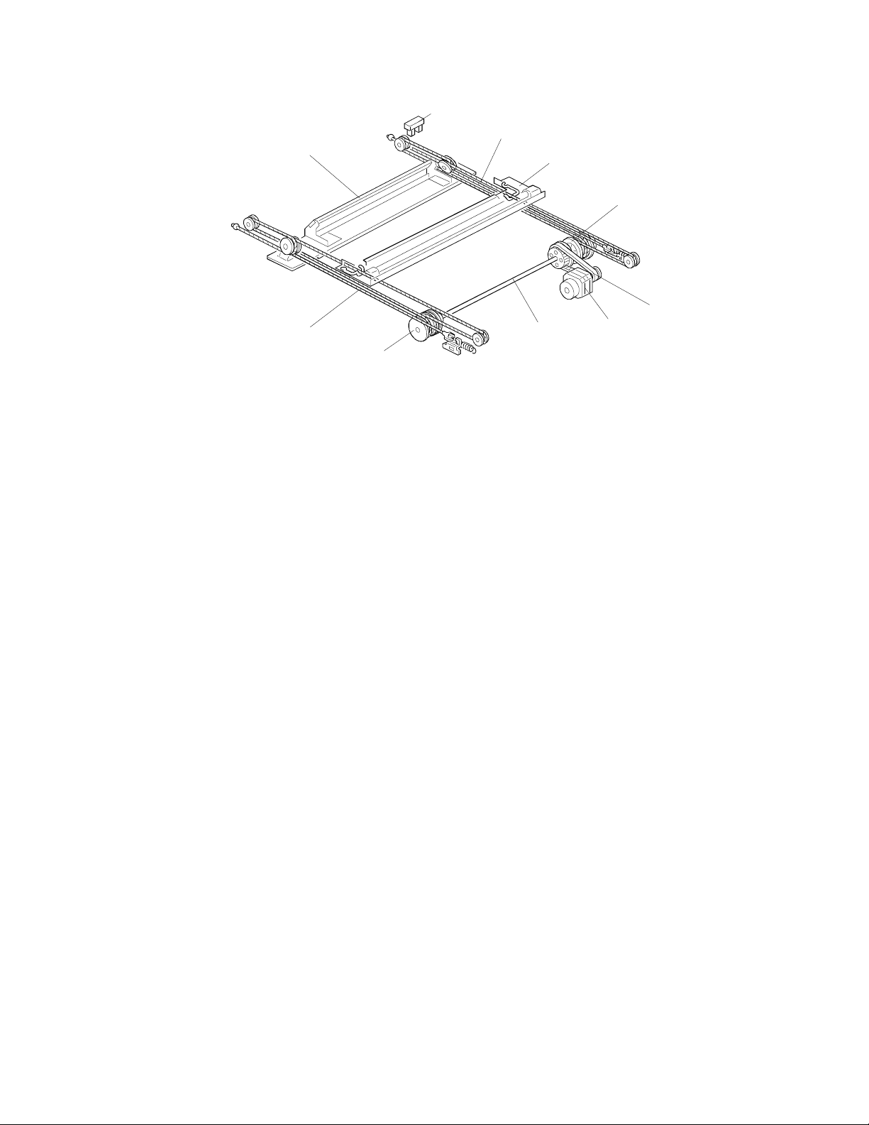
1.2 SCANNER DRIVE
[B]
[H]
[G]
[A]
[E]
[D]
[G]
[F]
[C]
[E]
A193D546.wmf
A stepper motor is used to drive the scanner. The 1st and 2nd scanners [A,B]
are driven by this scanner drive motor [C] through the timing belt [D], scanner
drive pulley [E], scanner drive shaft [F], and two scanner wires [G].
– Book mode –
The scanner drive board controls and operates the scanner drive motor. In
full size mode, the 1st scanner speed is 90 mm/s during scanning. The 2nd
scanner speed is half that of the 1st scanner.
In reduction or enlargement mode, the scanning speed depends on the
magnification ratio (M: 0.25 to 4.00). The returning speed is always the same,
whether in full size or magnification mode. The image length change in the
sub scan direction is done by changing the scanner drive motor speed, and
in the main scan direction it is done by image processing on the BICU board.
Magnification in the sub-scan direction can be adjusted by changing the
scanner drive motor speed using SP4-101. Magnification in the main scan
direction can be adjusted using SP4-008.
– ADF mode –
The scanners are always kept at their home position (the scanner H.P sensor
[H] detects the 1st scanner) to scan the original. The ADF motor feeds the
original through the ADF. In reduction/enlargement mode, the image length
change in the sub-scan direction is done by changing the ADF motor speed.
Magnification in the main scan direction is done in the BICU board, like for
book mode.
Magnification in the sub-scan direction can be adjusted by changing the ADF
motor speed using SP6-007. In the main scan direction, it can be adjusted
with SP4-008, like for book mode.
2-2
1 August 1996 SCANNING
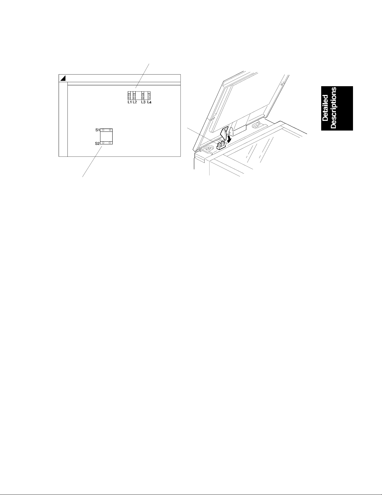
1.3 ORIGINAL SIZE DETECTION IN PLATEN MODE
[B]
[C]
A193D526.wmf
[A]
A193D003.wmf
In the optics cavity for original size detection, there are four reflective sensors
in the 115V machines, and six reflective sensors in the 230V machines. The
Original Width Sensors [A] detect the original width, and the Original Length
Sensors [B] detect the original length. These are the APS (Auto Paper
Select) sensors. Each APS sensor is a reflective photosensor.
While the main switch is on, these sensors are active and the original size
data is always sent to the CPU. However, the CPU checks the data only
when the platen cover is opened.
The original size data is taken by the main CPU when the platen cover
sensor [C] is activated. This is when the platen is positioned about 15 cm
above the exposure glass. At this time, only the sensor(s) located underneath
the original receive the reflected light and switch on. The other sensor(s) are
off. The main CPU can recognize the original size from the on/off signals
from the APS sensors.
If the copy is made with the platen fully open, the main CPU decides the
original size from the sensor outputs when the Start key is pressed.
2-3

SCANNING 1 August 1996
Original Size Length Sensors
A4/A3 version LT/DLT versi on
A3 11" x 17" OOOOOO
B4 10" x 14" OOOOOX
1/2
F4 8
A4–L 8
B5–L — OXXXXX
A4–S 11" x 8
B5–S — X X X X O X
" x 14" (8" x 13") O O O X X X
1/2
" x 11" OOXXXX
1/2
" XXXXOO
L1 L2 L3 L4 S1 S2
Width
Sensors
O: ON X: OFF
NOTE:
The length sensors L3 and L4 are used only for 230V machines.
For other combinations, "CANNOT DETECT ORIG. SIZE" will be indicated
on the operation panel display.
The above table shows the outputs of the sensors for each original size. This
original size detection method eliminates the necessity for a pre-scan and
increases the machine’s productivity.
However, if the by-pass feeder is used, note that the machine assumes that
the copy paper is lengthwise. For example, if A4 sideways paper is placed on
the by-pass tray, the machine assumes it is A3 paper and scans the full A3
area, disregarding the original size sensors. This can cause excess toner to
be transferred to the transfer roller, so users should be instructed to always
set the paper lengthwise on the by-pass tray. This problem occurs for the first
page only. The registration sensor detects the length of the first page, and
will assume that the following sheets of copy paper are the same length.
Original size detection using the ADF is described in the manual for the ADF.
2-4
1 August 1996 IMAGE PROCESSING
2. IMAGE PROCESSING
2.1 OVERVIEW
SBU
CCD
Fax Controller
X
T
IPU
MSU
Printer
Controller
Drum
LDDR
LD Driver
Controller
BICU
LD
(GAVD)
X
R
FCI
Fax
Controller
A193D501.wmf
The CCD generates an analog video signal. The SBU (Sensor Board Unit)
converts the analog signal to an 8-bit digital signal, then it sends the digital
signal to the BICU (Base-engine and Image Control Unit) board.
The BICU board can be divided into three image processing blocks; the IPU
(Image Processing Unit), FCI (Fine Character Image), and LD controller
(GAVD)
IPU: Auto shading, filtering, magnification, γ correction, and gradation
•
processing
FCI: Smoothing (binary picture processing mode only)
•
LD controller: LD print timing control and laser power PWM control
•
Finally, the BICU board sends the video data to the LD drive board at the
correct time.
2-5
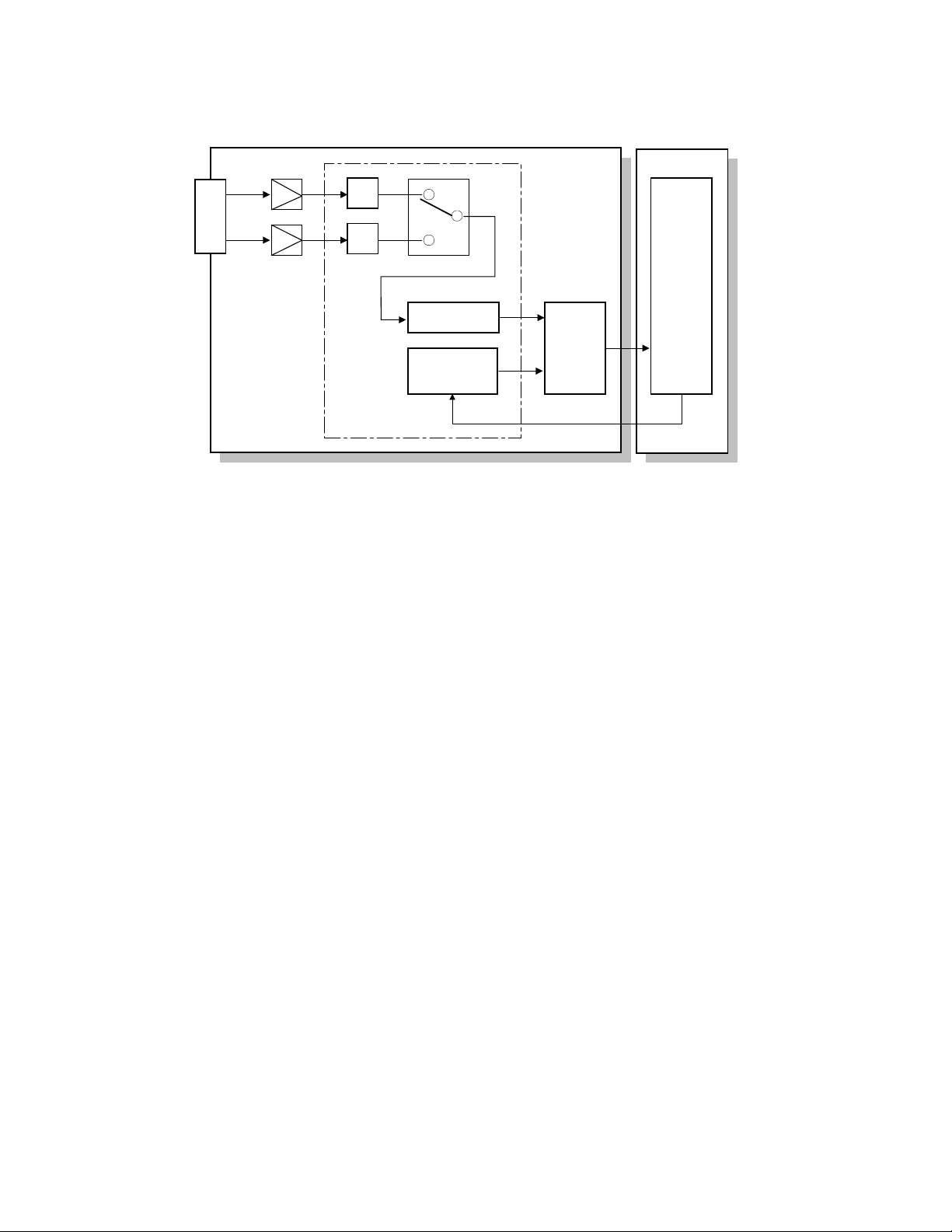
IMAGE PROCESSING 1 August 1996
2.2 SBU (SENSOR BOARD UNIT)
ODD
CCD
EVEN
Amp.
SBU
Z/C
Z/C
BICU
IPU
AGC
Reference
Controller
A/D
Vin
ref
Analog
Processing IC
Z/C: Zero Clamp
AGC: Automatic Gain Control Circuit
A193D502.wmf
The CCD converts the light reflected from the original into an analog signal.
The CCD line has 5,000 pixels and the resolution is 400 dpi (15.7 lines/mm).
The CCD has two output lines, for odd and even pixels, to the analog
processing IC. The analog processing IC performs the following operations
on the signals from the CCD:
1) Z/C (Zero Clamp):
Adjusts the black level reference for even pixels to match the odd pixels.
2) Signal Composition:
Analog signals for odd and even pixels from the CCD are merged by a
switching device.
3) Signal Amplification
The analog signal is amplified by operational amplifiers in the AGC circuit.
The maximum gains of the operational amplifiers are controlled by the
CPU on the BICU board.
After the above processing, the analog signals are converted to 8-bit signals
by the A/D converter. This will give a value for each pixel on a scale of 256
grades. Then, the digitized image data goes to the BICU board.
2-6
1 August 1996 IMAGE PROCESSING
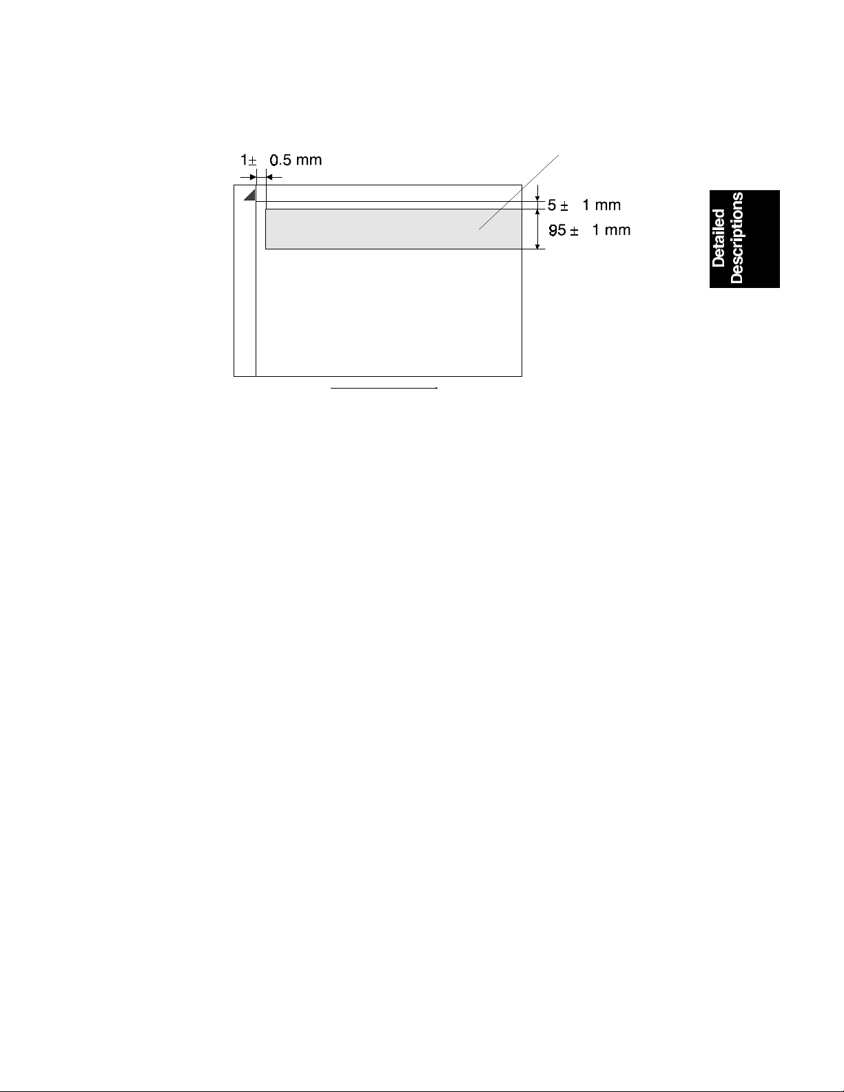
2.3 AUTO IMAGE DENSITY (ADS)
[A]
Sub scan di rection
A193D004 .w m f
This mode prevents the background of an original from appearing on copies.
The copier scans the auto image density detection area [A] as shown in the
diagram. This corresponds to a few mm at one end of the main scan line. As
the scanner scans down the page, the IPU on the BICU detects the peak
white level for each scan line. The IPU determines the reference value for the
A/D conversion for a particular scan line using the peak white level for that
scan line. Then, the IPU sends the reference value data to the reference
controller on the SBU.
When an original with a gray background is scanned, the density of the gray
area is the peak white level density. Therefore, the original background will
not appear on copies. Because peak level data is taken for each scan line,
ADS corrects for any changes in background density down the page.
As with previous digital copiers, the user can select manual image density
when selecting auto image density mode, and the machine will use both
settings when processing the original.
2-7
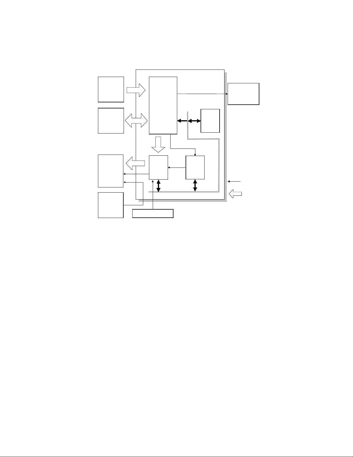
IMAGE PROCESSING 1 August 1996
2.4 IPU (IMAGE PROCESS ING UNIT )
2.4.1 Overview
BICU
SBU
MSU
LD
Unit
Printer
controller
+
IPU
+
+
GAVD FCI
+
R
x
Fax Controller
Tx
CPU BUS
+
CPU
Fax controller
1 bit
Data
8 bit
+
Data
A193D527.wmf
The image data from the SBU goes to the IPU (Image Processing Unit) IC on
the BICU board, which carries out the following processes on the image data:
1. Auto shading
2. Filtering (MTF and smoothing)
3. Magnification
4. γ correction
5. Grayscale processing
6. Binary picture processing
7. Error diffusion
8. Dithering
9. Video path control
10. Test pattern generation
The image data then goes to either the LD controller (GAVD) or the FCI
depending on the selected copy modes.
2-8
1 August 1996 IMAGE PROCESSING
2.4.2 Image Processing Path
SBU
Text mode
Text/Photo
mode Photo mode
MTF
Correction
Grayscale
Processing
Line Width
Correction
Fax Controller
Smoothing
Dithering Error Diffusion
Correction
γ
(Scanner)
ADS and Auto
Shading
Main Scan
Magnification/
Reduction
Binary Picture
Image Compression/
Decompression, Image
Rotation/Adjust Image
IPU
Processing
MSU
Controller
BICU
Printer
Video Path Controller
Laser Diode Power
Modulation
Correction (Printer)
γ
LDDR
2-9
Edge Smoothing
Line Width Correction
FCI
A193D506.wmf
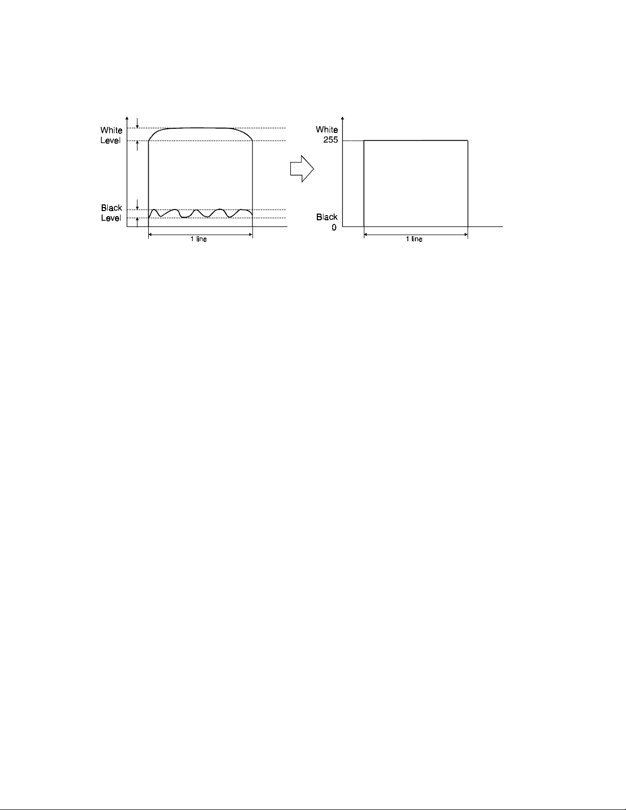
IMAGE PROCESSING 1 August 1996
2.4.3 Auto Shading
A193D517.wmf
As with the previous digital copiers, there are two auto shading methods. One
is black level correction and the other is white level correction. Auto shading
corrects errors in the signal level for each pixel.
1) Black Level Correction
The CPU reads the black dummy data from one end of the CCD signal (64
pixels at the end are blacked off) and takes the average of the black dummy
data. Then, the CPU deletes the black level value from each image pixel.
2) White Level Correction
Before scanning the original, the machine reads a reference waveform from
the white plate. The average of the white video level for each pixel is stored
as the white shading data in the FIFO memory in the IPU chip.
The video signal information for each pixel obtained during image scanning is
corrected by the IPU chip.
In book mode, auto shading is done at the beginning of each scan.
In ADF mode, auto shading is done at a specific time interval. This interval
can be set with SP4-913 (the default setting is 30 seconds). The machine
waits until the end of the page before doing the auto shading.
2-10
1 August 1996 IMAGE PROCESSING
2.4.4 Filtering and Main Scan Magni fi cation/Reduction
1. Overview
After auto shading, the image data is processed by both filtering and main
scan magnification. However, to reduce the occurrence of moire in the image,
the processing order is different depending on the reproduction ratio, as
follows.
1) Reduction and Full size
Main Scan Reduction → Filtering
2) Enlargement
Filtering → Main Scan Magnification
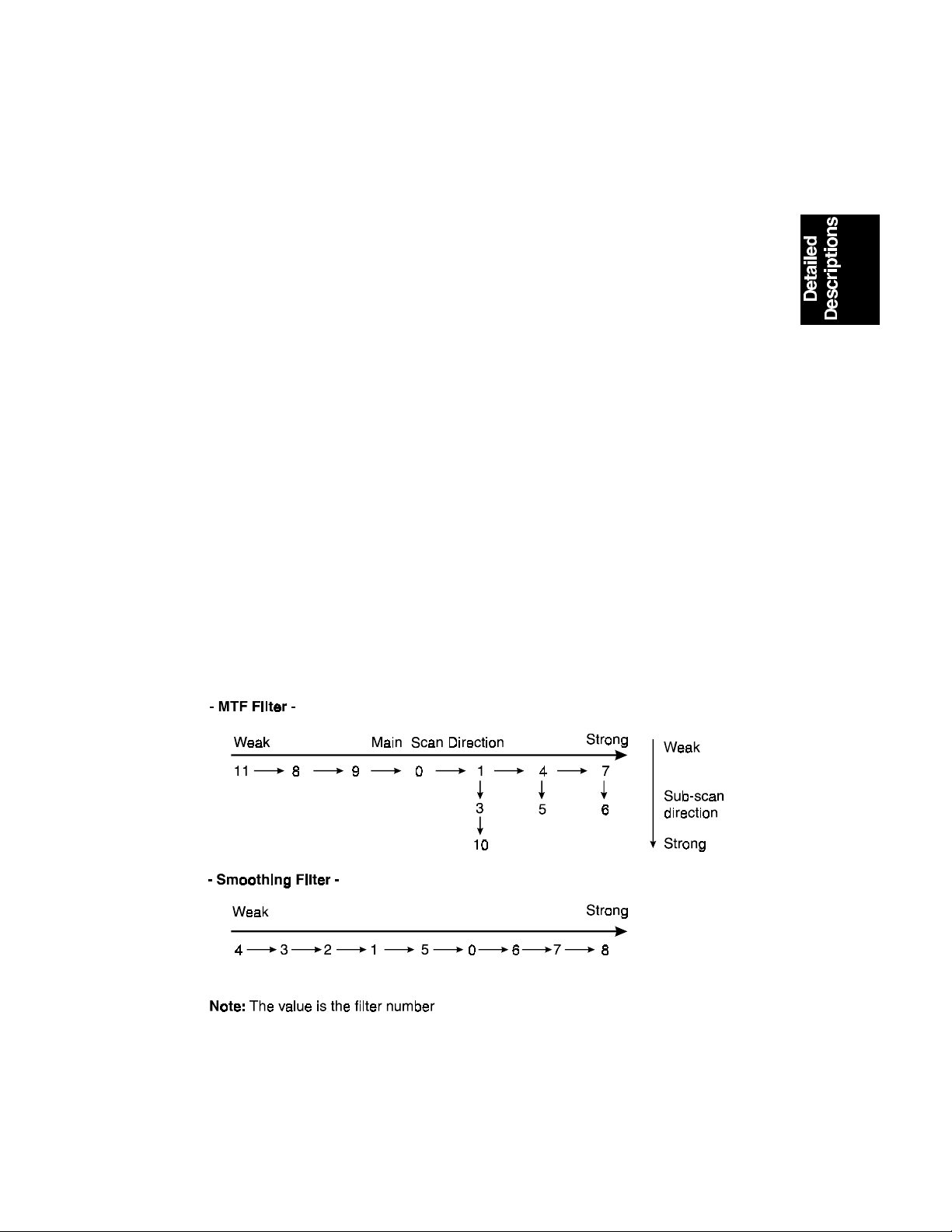
2. Filtering
There are two software filters for enhancing the desired image qualities of the
selected original mode: the MTF filter and the smoothing filter.
The MTF filter emphasizes sharpness and is used in Text and Text/Photo
modes. The smoothing filter is used in Photo mode.
The relationships between the coefficient of the filter and the filter strengths
are as follows. Note that these relationships are for copier mode only. Fax
mode has its own unique table. (Refer to the fax section.)
The filter strengths for each mode can be adjusted with SP4-407.
NOTE:
Never select "1." Abnormal images may result.
2-11
A193D503.wmf
 Loading...