

Page 1

TABLE OF CONTENTS
1. OVERALL MACHINE INFORMATION........................................ 1-1
1.1 SPECIFICATIONS.....................................................................................1-1
1.1.1 COPIER ENGINE.............................................................................1-1
1.1.2 ADF ..................................................................................................1-4
1.2 MACHINE CONFIGURATION...................................................................1-5
1.3 COMPONENT LAYOUT............................................................................1-6
1.3.1 COPIER ENGINE.............................................................................1-6
1.3.2 ADF ..................................................................................................1-7
1.4 PAPER PATH............................................................................................1-8
1.5 COPY PROCESS......................................................................................1-9
1.6 DRIVE LAYOUT......................................................................................1-11
1.6.1 COPIER ENGINE...........................................................................1-11
1.6.2 ADF ................................................................................................1-12
1.7 ELECTRICAL COMPONENT DESCRIPTIONS......................................1-13
1.7.1 COPIER ENGINE...........................................................................1-13
1.7.2 ADF ................................................................................................1-19
2. DETAILED SECTION DESCRIPTIONS ...................................... 2-1
2.1 DOCUMENT FEEDER..............................................................................2-1
2.1.1 PICK-UP ROLLER RELEASE..........................................................2-1
2.1.2 BOTTOM PLATE LIFT......................................................................2-2
2.1.3 PICK-UP AND SEPARATION ..........................................................2-3
2.1.4 ORIGINAL FEED..............................................................................2-4
2.1.5 ORIGINAL SIZE DETECTION..........................................................2-5
2.1.6 ORIGINAL TRANSPORT.................................................................2-6
2.1.7 ORIGINAL SKEW CORRECTION....................................................2-7
2.1.8 ORIGINAL INVERSION AND FEED-OUT........................................2-8
2.1.9 JAM CONDITIONS.........................................................................2-12
2.2 SCANNING..............................................................................................2-13
2.2.1 OVERVIEW....................................................................................2-13
2.2.2 SCANNER DRIVE..........................................................................2-14
2.2.3 ORIGINAL SIZE DETECTION IN BOOK MODE............................2-15
2.3 IMAGE PROCESSING............................................................................2-17
2.3.1 OVERVIEW....................................................................................2-17
2.3.2 SBU................................................................................................2-18
2.3.3 AUTO IMAGE DENSITY (ADS)......................................................2-19
2.3.4 IMAGE PROCESSING STEPS AND RELATED SP MODE...........2-20
2.3.5 AUTO SHADING............................................................................2-26
2.3.6 BACKGROUND ERASE.................................................................2-27
2.3.7 INDEPENDENT DOT ERASE........................................................2-28
2.3.8 FILTERING, MAIN SCAN MAGNIFICATION/REDUCTION...........2-29
2.3.9 GAMMA (γ) CORRECTION............................................................2-31
2.3.10 GRADATION PROCESSING .......................................................2-31
2.3.11 LINE WIDTH CORRECTION........................................................2-32
A294 II-i
Page 2

2.4 LASER EXPOSURE................................................................................2-33
2.4.1 OVERVIEW....................................................................................2-33
2.4.2 OPTICAL PATH..............................................................................2-34
2.4.3 AUTO POWER CONTROL (APC)..................................................2-35
2.4.4 FOUR BEAM LASER WRITING.....................................................2-36
2.4.5 LD SAFETY SWITCHES................................................................2-37
2.5 DRUM UNIT ............................................................................................2-38
2.5.1 PROCESS CONTROL....................................................................2-38
2.5.2 TONER DENSITY CONTROL........................................................2-43
2.5.3 DRUM UNIT COMPONENTS.........................................................2-46
2.5.4 DRIVE.............................................................................................2-47
2.5.5 DRUM CHARGE.............................................................................2-48
2.5.6 DRUM CLEANING..........................................................................2-50
2.5.7 OTHERS.........................................................................................2-53
2.6 DEVELOPMENT.....................................................................................2-56
2.6.1 OVERVIEW....................................................................................2-56
2.6.2 DEVELOPMENT MECHANISM......................................................2-57
2.6.3 DRIVE.............................................................................................2-58
2.6.4 CROSSMIXING..............................................................................2-59
2.6.5 DEVELOPMENT BIAS...................................................................2-60
2.7 TONER SUPPLY AND RECYCLING ......................................................2-61
2.7.1 TONER BANK................................................................................2-61
2.7.2 SUPPLYING TONER TO THE DEVELOPMENT UNIT..................2-65
2.7.3 TONER HOPPER...........................................................................2-66
2.7.4 TONER RECYCLING AND WASTE TONER COLLECTION..........2-68
2.8 PAPER FEED..........................................................................................2-71
2.8.1 OVERVIEW....................................................................................2-71
2.8.2 DRIVE.............................................................................................2-72
2.8.3 PAPER LIFT – TRAYS 2 & 3..........................................................2-73
2.8.4 PICK-UP AND FEED – TRAYS 1 TO 3..........................................2-75
2.8.5 REMAINING PAPER/
PAPER END DETECTION – TRAYS 2 & 3....................................2-79
2.8.6 PAPER SIZE DETECTION – TRAYS 2 & 3....................................2-80
2.8.7 TRAY LOCK – TRAYS 2 & 3..........................................................2-81
2.8.8 TANDEM FEED – TRAY 1 .............................................................2-82
2.8.9 VERTICAL TRANSPORT...............................................................2-89
2.8.10 PAPER REGISTRATION..............................................................2-90
2.9 IMAGE TRANSFER AND PAPER SEPARATION...................................2-93
2.9.1 OVERVIEW....................................................................................2-93
2.9.2 IMAGE TRANSFER AND PAPER SEPARATION..........................2-94
2.9.3 TRANSFER BELT UNIT LIFT.........................................................2-96
2.9.4 PAPER TRANSPORTATION AND BELT DRIVE...........................2-97
2.9.5 TRANSFER BELT CLEANING.......................................................2-98
2.9.6 TONER COLLECTION...................................................................2-99
2.9.7 TRANSFER ANTI-CONDENSATION HEATER............................2-100
2.10 FUSING...............................................................................................2-101
2.10.1 OVERVIEW................................................................................2-101
2.10.2 FUSING ENTRANCE GUIDE.....................................................2-102
2.10.3 FUSING UNIT DRIVE.................................................................2-103
A294 II-ii
Page 3

2.10.4 FUSING LAMP CONTROL.........................................................2-104
2.10.5 OIL SUPPLY AND CLEANING...................................................2-105
2.10.6 PAPER COOLING......................................................................2-106
2.10.7 FUSING PRESSURE.................................................................2-107
2.10.8 HOT ROLLER STRIPPER RELEASE........................................2-108
2.11 PAPER EXIT/DUPLEX........................................................................2-109
2.11.1 OVERVIEW................................................................................2-109
2.11.2 PAPER EXIT MECHANISM........................................................2-110
2.11.3 DUPLEX DRIVE MECHANISM ..................................................2-111
2.11.4 INVERTER .................................................................................2-112
2.11.5 DUPLEX TRAY FEED MECHANISM.........................................2-114
2.11.6 BASIC DUPLEX FEED OPERATION.........................................2-115
2.12 ENERGY SAVER MODES..................................................................2-119
2.12.1 OVERVIEW................................................................................2-119
2.12.2 ENERGY SAVER (PANEL OFF) MODE ....................................2-120
2.12.3 LOW POWER MODE.................................................................2-121
2.12.4 OFF MODE.................................................................................2-122
2.12.5 SUMMARY.................................................................................2-124
2.13 OTHERS .............................................................................................2-125
2.13.1 OPERATION UNIT.....................................................................2-125
2.13.2 DOOR SAFETY SWITCH LOCK TOOLS...................................2-126
2.13.3 HDD CONTROL.........................................................................2-127
2.13.4 DATA PATH THROUGH THE INTERFACE BOARD.................2-129
3. INSTALLATION PROCEDURE................................................... 3-1
3.1 INSTALLATION REQUIREMENTS...........................................................3-1
3.1.1 ENVIRONMENT...............................................................................3-1
3.1.2 MACHINE LEVEL.............................................................................3-1
3.1.3 MINIMUM SPACE REQUIREMENTS...............................................3-2
3.1.4 POWER REQUIREMENTS..............................................................3-2
3.2 COPIER (A294).........................................................................................3-3
3.2.1 ACCESSORY CHECK......................................................................3-3
3.2.2 INSTALLATION PROCEDURE........................................................3-5
3.3 FINISHER INSTALLATION (B302)..........................................................3-12
3.3.1 ACCESSORY CHECK....................................................................3-12
3.3.2 INSTALLATION PROCEDURE......................................................3-13
3.4 LCT INSTALLATION (B303)....................................................................3-16
3.4.1 ACCESSORY CHECK....................................................................3-16
3.4.2 INSTALLATION PROCEDURE......................................................3-17
3.5 PUNCH UNIT INSTALLATION (A812)....................................................3-19
3.5.1 ACCESSORY CHECK....................................................................3-19
3.5.2 PUNCH UNIT INSTALLATION.......................................................3-20
3.6 A3/DLT TRAY (B331)..............................................................................3-23
3.6.1 ACCESSORY CHECK....................................................................3-23
3.6.2 INSTALLATION PROCEDURE......................................................3-24
3.7 KEY COUNTER INSTALLATION............................................................ 3-27
3.8 INTERFACE BOARD
(CD-RW/TANDEM COPY KIT/PRINTER CONTROLLER)......................3-30
3.8.1 INSTALLATION PROCEDURE......................................................3-30
A294 II-iii
Page 4

4 SERVICE TABLES....................................................................... 4-1
4.1 GENERAL CAUTIONS..............................................................................4-1
4.1.1 DRUM...............................................................................................4-1
4.1.2 DRUM UNIT .....................................................................................4-1
4.1.3 TRANSFER BELT UNIT...................................................................4-2
4.1.4 SCANNER UNIT...............................................................................4-2
4.1.5 LASER UNIT ....................................................................................4-2
4.1.6 CHARGE CORONA..........................................................................4-3
4.1.7 DEVELOPMENT ..............................................................................4-3
4.1.8 CLEANING.......................................................................................4-4
4.1.9 FUSING UNIT...................................................................................4-4
4.1.10 PAPER FEED.................................................................................4-4
4.1.11 USED TONER................................................................................4-4
4.2 SERVICE PROGRAM MODE....................................................................4-5
4.2.1 SERVICE PROGRAM MODE OPERATION.....................................4-5
4.2.2 SERVICE PROGRAM MODE TABLES..........................................4-10
4.2.3 TEST PATTERN PRINTING (SP2-902) .........................................4-59
4.2.4 INPUT CHECK...............................................................................4-60
4.2.5 OUTPUT CHECK...........................................................................4-68
4.2.6 SYSTEM PARAMETER AND DATA LISTS (SMC LISTS) .............4-70
4.2.7 MEMORY ALL CLEAR (SP5-801)..................................................4-70
4.2.8 SOFTWARE RESET......................................................................4-71
4.2.9 SYSTEM SETTING AND
COPY SETTING (UP MODE) RESET............................................4-71
4.3 PM COUNTER ........................................................................................4-72
4.3.1 PM COUNTER ACCESS PROCEDURE........................................4-72
4.4 PROGRAM DOWNLOAD........................................................................4-78
4.5 NVRAM DATA DOWNLOAD...................................................................4-80
4.6 LANGUAGE DATA DOWNLOAD............................................................4-81
4.7 STAMP DATA DOWNLOAD....................................................................4-81
4.8 USER PROGRAM MODE.......................................................................4-82
4.8.1 HOW TO ENTER AND EXIT UP MODE.........................................4-82
4.8.2 UP MODE TABLE ..........................................................................4-82
4.8.3 IMAGE QUALITY SETTING BY UP MODE....................................4-85
4.8.4 LEDS..............................................................................................4-91
4.9 TEST POINTS/DIP SWITCHES/LEDS....................................................4-92
4.9.1 DIP SWITCHES..............................................................................4-92
4.9.2 TEST POINTS................................................................................4-93
4.9.3 FUSES............................................................................................4-93
4.9.4 VARIABLE RESISTORS................................................................4-93
4.10 SPECIAL TOOLS AND LUBRICANTS..................................................4-94
4.10.1 SPECIAL TOOLS.........................................................................4-94
4.10.2 LUBRICANTS...............................................................................4-94
5 PREVENTIVE MAINTENANCE SCHEDULE............................... 5-1
5.1 PM PARTS................................................................................................5-1
A294 II-iv
Page 5

6. REPLACEMENT AND ADJUSTMENT........................................ 6-1
6.1 EXTERIOR................................................................................................6-1
6.1.1 FRONT.............................................................................................6-1
6.1.2 RIGHT ..............................................................................................6-2
6.1.3 LEFT.................................................................................................6-3
6.1.4 REAR................................................................................................6-4
6.2 DOCUMENT FEEDER..............................................................................6-5
6.2.1 COVER REMOVAL..........................................................................6-5
6.2.2 FEED UNIT REMOVAL AND
SEPARATION ROLLER REPLACEMENT .......................................6-7
6.2.3 FEED BELT REPLACEMENT..........................................................6-8
6.2.4 PICK-UP ROLLER REPLACEMENT................................................6-9
6.2.5 SENSOR REPLACEMENT.............................................................6-10
6.2.6 TRANSPORT BELT REPLACEMENT............................................6-14
6.2.7 MOTOR REPLACEMENT..............................................................6-15
6.2.8 FEED-IN CLUTCH REPLACEMENT..............................................6-17
6.3 SCANNER UNIT......................................................................................6-18
6.3.1 EXPOSURE GLASS.......................................................................6-18
6.3.2 LENS BLOCK.................................................................................6-19
6.3.3 ORIGINAL SIZE SENSORS...........................................................6-20
6.3.4 EXPOSURE LAMP.........................................................................6-21
6.3.5 LAMP REGULATOR.......................................................................6-22
6.3.6 OPTICS DUST FILTER..................................................................6-23
6.3.7 SCANNER H.P. SENSOR..............................................................6-24
6.3.8 SCANNER MOTOR........................................................................6-25
6.3.9 SCANNER DRIVE WIRES .............................................................6-26
6.4 LASER UNIT...........................................................................................6-29
6.4.1 CAUTION DECAL LOCATIONS.....................................................6-29
6.4.2 LDB AND LD FILTER REPLACEMENT .........................................6-30
6.4.3 POLYGON MIRROR MOTOR REPLACEMENT ............................6-31
6.4.4 LASER SYNCHRONIZATION DETECTOR REPLACEMENT........6-32
6.5 DRUM UNIT ............................................................................................6-33
6.5.1 DRUM UNIT REMOVAL AND DRUM REPLACEMENT.................6-33
6.5.2 QUENCHING LAMP REPLACEMENT...........................................6-34
6.5.3 GRID PLATE/CHARGE CORONA WIRE/
WIRE CLEANER REPLACEMENT ................................................6-35
6.5.4 DRUM POTENTIAL SENSOR REPLACEMENT............................6-37
6.5.5 CLEANING BLADE/ID SENSOR REPLACEMENT........................6-38
6.5.6 CLEANING BRUSH REPLACEMENT............................................6-39
6.5.7 PICK-OFF PAWL REPLACEMENT................................................6-40
6.5.8 DRUM FILTER REPLACEMENT....................................................6-41
6.6 DEVELOPMENT AND TONER SUPPLY................................................6-42
6.6.1 DEVELOPMENT UNIT REMOVAL.................................................6-42
6.6.2 DEVELOPER REPLACEMENT......................................................6-43
6.6.3 DEVELOPMENT AND AIR DUST FILTER REPLACEMENT.........6-45
6.6.4 DEVELOPMENT ENTRANCE, FRONT, AND
REAR SIDE SEALS........................................................................6-46
6.6.5 TONER DENSITY SENSOR REPLACEMENT...............................6-47
A294 II-v
Page 6

6.6.6 TONER HOPPER SENSOR REPLACEMENT...............................6-48
6.6.7 DEVELOPMENT MOTOR REPLACEMENT ..................................6-49
6.6.8 DEVELOPMENT ROLLER SHAFT CLEANING.............................6-50
6.7 TRANSFER BELT UNIT..........................................................................6-51
6.7.1 TRANSFER BELT UNIT REMOVAL/INSTALLATION....................6-51
6.7.2 TRANSFER BELT REPLACEMENT...............................................6-53
6.7.3 TRANSFER BELT CLEANING BLADE REPLACEMTNT...............6-55
6.7.4 TRANSFER BELT BIAS BRUSH REPLACEMENT........................6-56
6.8 PAPER FEED..........................................................................................6-57
6.8.1 PAPER TRAY REMOVAL..............................................................6-57
6.8.2 PAPER FEED ROLLER REPLACEMENT......................................6-60
6.8.3 PAPER FEED AND VERTICAL TRANSPORT CLUTCH, AND
TRAY LIFT, PAPER FEED, AND
PAPER END SENSOR REMOVAL...............................................6-61
6.8.4 REAR FENCE RETURN SENSOR REPLACEMENT.....................6-64
6.8.5 REAR FENCE HP SENSOR REPLACEMENT...............................6-65
6.8.6 RIGHT 1ST TRAY PAPER SENSOR REPLACMENT....................6-66
6.8.7 BOTTOM PLATE LIFT WIRE REPLACEMENT .............................6-67
6.8.8 PAPER DUST REMOVER CLEANING..........................................6-69
6.8.9 REGISTRATION SENSOR CLEANING.........................................6-70
6.8.10 UNIVERSAL TRAY SIZE SWITCH REPLACEMENT...................6-71
6.8.11 1ST TRAY LIFT MOTOR REMOVAL ...........................................6-72
6.8.12 LIFT MOTOR REMOVAL (2ND & 3RD TRAYS)...........................6-73
6.8.13 PAPER FEED MOTOR REMOVAL..............................................6-74
6.8.14 RELAY MOTOR, UPPER RELAY CLUTCH,
LCT RELAY CLUTCH REMOVAL................................................6-75
6.8.15 REGISTRATION MOTOR REMOVAL..........................................6-76
6.8.16 COPIER FEED UNIT/DEVELOPMENT FAN MOTOR
REMOVAL....................................................................................6-77
6.8.17 LCT RELAY AND RELAY SENSOR REMOVAL..........................6-78
6.8.18 TANDEM FEED TRAY PAPER SIZE CHANGE...........................6-79
6.8.19 MECHANICAL SIDE REGISTRATION ADJUSTMENT................6-82
6.9 FUSING UNIT..........................................................................................6-83
6.9.1 OIL SUPPLY & CLEANING WEB UNIT REMOVAL.......................6-83
6.9.2 HOT ROLLER UNIT REMOVAL AND
PRESSURE ROLLER REPLACEMENT.........................................6-84
6.9.3 HOT ROLLER REPLACEMENT.....................................................6-86
6.9.4 OIL SUPPLY & CLEANING WEB REPLACEMENT.......................6-88
6.9.5 WEB CLEANING ROLLER REPLACEMENT.................................6-90
6.9.6 HOT ROLLER STRIPPER REPLACEMENT..................................6-91
6.9.7 PRESSURE ROLLER STRIPPER REPLACEMENT......................6-92
6.9.8 PRESSURE ROLLER CLEANING ROLLER REPLACEMENT......6-93
6.9.9 FUSING AND EXIT UNIT REMOVAL.............................................6-94
6.9.10 FUSING PRESSURE ADJUSTMENT..........................................6-95
6.10 PAPER EXIT/DUPLEX UNIT.................................................................6-96
6.10.1 EXIT SENSOR REPLACEMENT..................................................6-96
6.10.2 DUPLEX UNIT REMOVAL ...........................................................6-97
6.10.3 DUPLEX UNIT INNER COVER REMOVAL..................................6-98
6.10.4 JOGGER MOTOR REPLACEMENT ............................................6-99
A294 II-vi
Page 7

6.10.5 DUPLEX UNIT CLUTCH REPLACEMENT.................................6-100
6.10.6 DUPLEX ENTRANCE SENSOR REPLACEMENT.....................6-101
6.10.7 DUPLEX TRANSPORT SENSORS 2 & 3 ..................................6-102
6.10.8 DUPLEX TRANSPORT SENSOR 1/
DUPLEX INVERTER SENSOR..................................................6-103
6.11 TONER BANK.....................................................................................6-104
6.11.1 WASTE TONER BOTTLE REMOVAL........................................6-104
6.11.2 TONER BANK UNIT REMOVAL ................................................6-105
6.11.3 TONER SUPPLY MOTOR AND
TONER SUPPLY MOTOR SENSOR REMOVAL.......................6-108
6.11.4 ACCESS TO INSIDE THE TONER BANK..................................6-109
6.12 BOARDS AND OTHER ITEMS...........................................................6-110
6.12.1 SICU BOARD.............................................................................6-110
6.12.2 HARD DISK DRIVE....................................................................6-111
6.12.3 BCU BOARD..............................................................................6-112
6.12.4 I/O BOARD.................................................................................6-113
6.12.5 PSU............................................................................................6-114
6.12.6 CHARGE/GRID/BIAS POWER PACK........................................6-115
6.12.7 FUSING/DUPLEX MOTOR REPLACEMENT.............................6-116
6.12.8 DRUM MOTOR REPLACEMENT...............................................6-117
6.13 COPY IMAGE ADJUSTMENT: PRINTING/SCANNING......................6-118
6.13.1 PRINTING ..................................................................................6-118
6.13.2 PARALLELOGRAM IMAGE ADJUSTMENT ..............................6-121
6.13.3 SCANNING.................................................................................6-123
6.13.4 ADF IMAGE ADJUSTMENT.......................................................6-124
6.14 TOUCH SCREEN CALIBRATION.......................................................6-125
7 TROUBLESHOOTING ................................................................. 7-1
7.1 SERVICE CALL CONDITIONS.................................................................7-1
7.1.1 SUMMARY.......................................................................................7-1
7.1.2 SC CODE DESCRIPTIONS .............................................................7-2
7.2 ELECTRICAL COMPONENT DEFECTS ................................................7-37
7.2.1 SENSORS......................................................................................7-37
7.2.2 SWITCHES.....................................................................................7-41
7.3 BLOWN FUSE CONDITIONS.................................................................7-42
A294 II-vii
Page 8

OPTION
3,000-SHEET FINISHER (B302)
1. OVERALL MACHINE INFORMAT ION..................................B302-1
1.1 SPECIFICATIONS.............................................................................. B302-1
1.2 MECHANICAL COMPONENT LAYOUT ............................................ B302-3
1.3 ELECTRICAL COMPONENT DESCRIPTION.................................... B302-4
1.4 DRIVE LAYOUT................................................................................. B302-6
2. DETAILED DESCRIPTIONS.................................................B302-7
2.1 TRAY AND STAPLER JUNCTION GATE.......................................... B302-7
2.2 PAPER PRE-STACKING ................................................................... B302-8
2.3 JOGGER UNIT PAPER POSITIONING ............................................. B302-9
2.4 STAPLER UNIT MOVEMENT.......................................................... B302-10
2.5 STAPLER......................................................................................... B302-12
2.6 FEED-OUT....................................................................................... B302-14
2.7 SHIFT TRAY UP/DOWN MOVEMENT............................................. B302-15
2.8 SHIFT TRAY SIDE-TO-SIDE MOVEMENT...................................... B302-16
2.9 PUNCH UNIT DRIVE ....................................................................... B302-17
2.10 PUNCH WASTE COLLECTION..................................................... B302-18
2.11 JAM CONDITIONS......................................................................... B302-19
3. SERVICE TABLES..............................................................B302-20
3.1 DIP SWITCHES................................................................................ B302-20
3.2 TEST POINTS.................................................................................. B302-20
3.3 FUSES ............................................................................................. B302-20
4. REPLACEMENT AND ADJUSTMENT................................B302-21
4.1 COVER REPLACEMENT................................................................. B302-21
4.2 POSITIONING ROLLER REPLACEMENT ....................................... B302-24
4.3 ALIGNMENT BRUSH ROLLER REPLACEMENT............................ B302-25
4.4 SENSOR REPLACEMENT .............................................................. B302-26
4.4.1 STACK HEIGHT 1, 2 AND EXIT GUIDE OPEN SENSOR...... B302-26
4.4.2 UPPER TRAY PAPER LIMIT AND EXIT SENSOR................. B302-27
4.4.3 SHIFT TRAY EXIT SENSOR................................................... B302-28
4.4.4 ENTRANCE AND
STAPLER TRAY ENTRANCE SENSORS .............................. B302-29
4.4.5 PRE-STACK STOPPER SENSOR .......................................... B302-30
4.4.6 STAPLE WASTE HOPPER SENSOR..................................... B302-31
4.4.7 STAPLER ROTATION HP AND
STAPLER RETURN SENSORS.............................................. B302-32
4.5 STAPLER REMOVAL....................................................................... B302-33
4.6 PUNCH POSITION ADJUSTMENT.................................................. B302-34
A294 II-viii
Page 9

LCT (B303)
1. OVERALL MACHINE INFORMAT ION..................................B303-1
1.1 SPECIFICATIONS.............................................................................. B303-1
1.2 MECHANICAL COMPONENT LAYOUT ............................................ B303-2
1.3 ELECTRICAL COMPONENT DESCRIPTIONS................................. B303-3
1.4 DRIVE LAYOUT................................................................................. B303-5
2. DETAILED DESCRIPTIONS.................................................B303-6
2.1 PAPER FEED..................................................................................... B303-6
2.2 PICK-UP AND FEED.......................................................................... B303-7
2.2.1 OVERVIEW............................................................................... B303-7
2.2.2 PICK-UP AND FEED................................................................. B303-8
2.2.3 SEPARATION ROLLER RELEASE........................................... B303-9
2.3 PAPER LIFT..................................................................................... B303-10
2.3.1 TRAY DETECTION................................................................. B303-10
2.3.2 LIFT MECHANISM.................................................................. B303-10
2.3.3 LIFT SENSOR......................................................................... B303-11
2.4 PAPER SIZE DETECTION............................................................... B303-12
2.5 PAPER END DETECTION............................................................... B303-13
3. REPLACEMENT AND ADJUSTMENT................................B303-14
3.1 EXTERIOR COVER REMOVAL....................................................... B303-14
3.2 INNER COVER REMOVAL.............................................................. B303-15
3.3 PAPER FEED ROLLER REPLACEMENT........................................ B303-16
3.4 LCT MOTOR REPLACEMENT.........................................................B303-17
3.5 RELAY SENSOR REPLACEMENT.................................................. B303-18
3.6 PAPER HEIGHT SENSOR AND
PAPER SIZE SWITCH REPLACEMENT ......................................... B303-19
3.7 MAIN DRIVE BELT REPLACEMENT............................................... B303-20
3.8 SIDE REGISTRATION ADJUSTMENT............................................ B303-21
A3/DLT TRAY KIT (B331)
1. OVERALL MACHINE INFORMAT ION..................................B331-1
1.1 SPECIFICATIONS.............................................................................. B331-1
2. DETAILED DESCRIPTIONS.................................................B331-2
2.1 SECTIONAL DESCRIPTION.............................................................. B331-2
3. REPLACEMENT AND ADJUSTMENT..................................B331-3
3.1 BOTTOM PLATE LIFT WIRE REPLACEMENT................................. B331-3
A294 II-ix
Page 10

CHANGES MADE FROM THE A294 I / A295 I MODELS
1 DETAILED SECTION DESCRIPTIONS ............................. A294 II-1
1.1 TONER AND DEVELOPER.............................................................A294 II-1
1.2 NEWLY ADDED: DEVELOPMENT S UCTION MOTOR AND
SUCKED TONER COLLECTION BOTTLE.....................................A294 II-1
1.3 DEVELOPMENT UNIT....................................................................A294 II-2
1.4 TONER BANK UNIT........................................................................A294 II-3
1.5 CLEANING UNIT.............................................................................A294 II-3
1.6 FUSING UNIT..................................................................................A294 II-4
1.7 NEW ADDITIONS TO TRANSFER CURRENT CONTROL ............A294 II-5
1.8 CHARGE CORONA UNIT...............................................................A294 II-6
1.9 ELECTRICAL COMPONENTS........................................................A294 II-6
2 SERVICE TABLES.............................................................A294 II-9
2.1 SERVICE PROGRAM MODE..........................................................A294 II-9
3 PREVENTIVE MAINTENANCE SCHEDULE................... A294 II-13
3.1 PM PARTS....................................................................................A294 II-13
4 TROUBLESHOOTING ..................................................... A294 II-14
4.1 SERVICE CALL CONDITIONS.....................................................A294 II-14
A294 II-x
Page 11

18 July, 2001 GENERAL CAUTIONS
4. SERVICE TABLES
4.1 GENERAL CAUTIONS
Do not turn off either of the power switches while any of the electrical components
are active. Doing so might cause damage to units such as the transfer belt, drum,
and development unit when they are pulled out of or put back into the copier.
4.1.1 DRUM
An organic photoconductor (OPC) drum is more sensitive to light and ammonia gas
than a selenium drum. Follow the cautions below when handling an OPC drum.
1. Never expose the drum to direct sunlight.
2. Never expose the drum to direct light of more than 1,000 Lux for more than a
minute.
3. Never touch the drum surface with bare hands. When the drum surface is
touched with a finger or becomes dirty, wipe it with a dry cloth or clean it with
wet cotton. Wipe with a dry cloth after cleaning with wet cotton.
4. Never use alcohol to clean the drum; alcohol dissolves the drum surface.
Tables
Service
5. Store the drum in a cool, dry place away from heat.
6. Take care not to scratch the drum as the drum layer is thin and is easily
damaged.
7. Never expose the drum to corrosive gases such as ammonia gas.
8. Always keep the drum in the protective sheet when keeping the drum unit, or
the drum itself, out of the copier. Doing so avoids exposing it to bright light or
direct sunlight, and will protect it from light fatigue.
9. Dispose of used drums in accordance with local regulations.
10. When installing a new drum, do the Auto Process Control Data Adjustment (SP
2-962).
4.1.2 DRUM UNIT
1. Before pulling out the drum unit, place a sheet of paper under the drum unit to
catch any spilt toner.
2. Make sure that the drum unit is set in position and the drum stay is secured
with a screw before the main switch is turned on. If the drum unit is loose, poor
contact of the drum connectors may cause electrical noise, resulting in
unexpected malfunctions (RAM data change is the worst case).
3. To prevent drum scratches, remove the development unit before removing the
drum unit.
4-1
Page 12

GENERAL CAUTIONS 18 July, 2001
4.1.3 TRANSFER BELT UNIT
1. Never touch the transfer belt surface with bare hands.
2. Take care not to scratch the transfer belt, as the surface is easily damaged.
3. Before installing the new transfer belt, clean all the rollers and the inner p art of
the transfer belt with a dry cloth to prevent the belt from slipping.
4.1.4 SCANNER UNIT
1. When installing the exposure glass, make sure that the white p aint is at the rear
left corner.
2. Clean the exposure glass with alcohol or glass cleaner to reduce the amount of
static electricity on the glass surface.
3. Use a cotton pad with water or a blower brush to clean the mirrors and lens.
4. Do not bend or crease the exposure lamp flat cable.
5. Do not disassemble the lens unit. Doing so will throw the lens and the copy
image out of focus.
6. Do not turn any of the CCD positioning screws. Doing so will throw the CCD out
of position.
4.1.5 LASER UNIT
1. Do not loosen the screws that secure the LD drive board to the laser diode
casing. Doing so would throw the LD unit out of adjustment.
2. Do not adjust the variable resistors on the LD unit, as they are adjusted in the
factory.
3. The polygon mirror and F-theta lenses are very sensitive to dust. Do not open
the optical housing unit.
4. Do not touch the glass surface of the polygon mirror motor unit with bare
hands.
4-2
Page 13

18 July, 2001 GENERAL CAUTIONS
4.1.6 CHARGE CORONA
1. Clean the corona wires with a dry cloth. Do not use sandpaper or solvent.
2. Clean the charge corona casing with water first to remove NOx based
compounds. Then clean it with alcohol if any toner still remains on the casing.
3. Clean the end block with a blower brush first to remove toner and paper dust.
Then clean with alcohol if any toner still remains.
4. Do not touch the corona wires with bare hands. Oil stains from fingers may
cause uneven image density on copies.
5. Make sure that the wires are correctly between the cleaner pads and that there
is no foreign material (iron filings, etc.) on the casing.
6. When installing new corona wires, do not bend or scratch the wire surface.
Doing so may cause uneven charge. Also be sure that the corona wires are
correctly positioned in the end blocks. (See Charge Corona Wire Replacement)
7. Clean the grid plate with a blower brush (not with a dry cloth).
8. Do not touch the charge grid plate with bare hands. Also, do not bend the
charge grid plate or make any dent in it. Doing so may cause uneven charge.
Tables
Service
4.1.7 DEVELOPMENT
1. Be careful not to nick or scratch the development roller.
2. Place the development unit on a sheet of paper after removing it from the
copier.
3. Never disassemble the development roller assembly. The position of the doctor
plate is set with special tools and instruments at the factory to ensure the
proper gap between the doctor blade and the development roller.
4. Clean the drive gears after removing used developer.
5. Dispose of used developer in accordance with local regulations.
6. Never load types of developer and toner into the development unit other than
specified for this model. Doing so will cause poor copy quality and toner
scattering.
7. Immediately after installing new developer, the TD sensor initial setting
procedure should be performed to avoid damage to the copier. Do not perform
the TD sensor initial setting with used developer. Do not make any copies
before doing the TD sensor initial setting.
8. When u sing a vacuum cleaner to clean the development unit casing, al ways
ground the casing with your fingers to avoid damaging the toner density sensor
with static electricity.
9. When replacing the TD sensor, the developer should be replaced and then the
TD sensor initial setting procedure (SP2-801) should be done, followed by
process control initialization (SP2-962).
4-3
Page 14

GENERAL CAUTIONS 18 July, 2001
4.1.8 CLEANING
1. When servicing the cleaning section, be careful not to damage the edge of the
cleaning blade.
2. Do not touch the cleaning blade with bare hands.
3. Before disassembling the cleaning section, place a sheet of paper under it to
catch any toner falling from it.
4.1.9 FUSING UNIT
1. After installing the fusing thermistor, make sure that it is in contact with the hot
roller and that it is movable.
2. Be careful not to damage the edges of the hot roller strippers or their tension
springs.
3. Do not touch the fusing lamp and rollers with bare hands.
4. Make sure that the fusing lamp is positioned correctly and that it does not touch
the inner surface of the hot roller.
4.1.10 PAPER FEED
1. Do not touch the surface of the pick-up, feed, and separation rollers.
2. To avoid paper misfeeds, the side fences and end fence of the paper tray must
be positioned correctly to align with the actual paper size.
4.1.11 USED TONER
1. We recommend checking the amount of used toner at every EM.
2. Dispose of used toner in accordance with local regulations. Never throw toner
into an open flame, for toner dust may ignite.
4-4
Page 15
18 July, 2001 SERVICE PROGRAM MODE
4.2 SERVICE PROGRAM MODE
4.2.1 SERVICE PROGRAM MODE OPERATION
The service program (SP) mode is used to check electrical data, change modes,
and adjust values.
Service Program Access Procedure
Entering SP mode
1) Press the following keys in sequence.
!
Hold the " key for more than 3 seconds.
2) A menu of SP modes is displayed on the LCD.
→
!
"
→
→
#
→
"
Tables
Service
A294M001.PCX
NOTE: The installed applications appear as Copy SP and Printer SP. If the
printer application is not installed, its name does not appear.
4-5
Page 16
SERVICE PROGRAM MODE 18 July, 2001
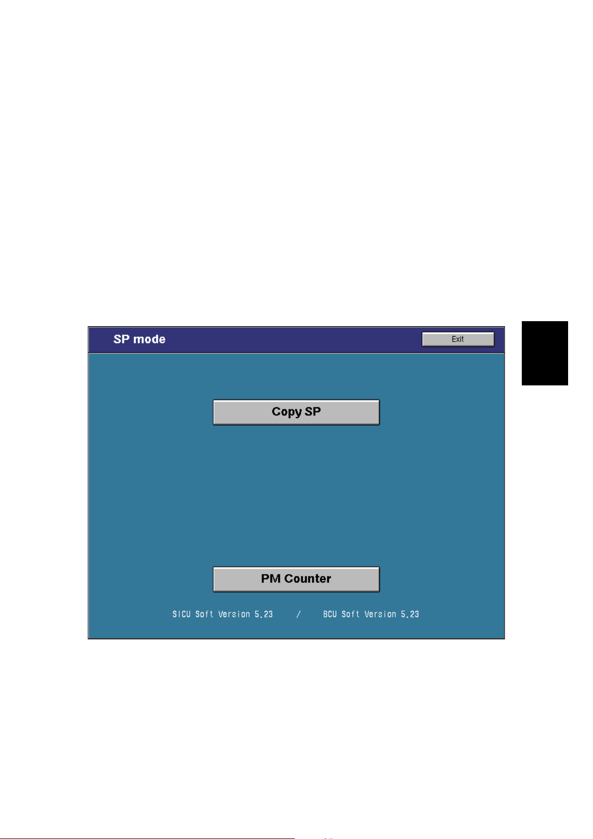
3) Touch the application which you need. Then, the application’s SP mode
display will appear, as shown.
A294M002.PCX
Exiting SP mode
1) Touch the “Exit” keys to return to the standby mode display.
4-6
Page 17
18 July, 2001 SERVICE PROGRAM MODE
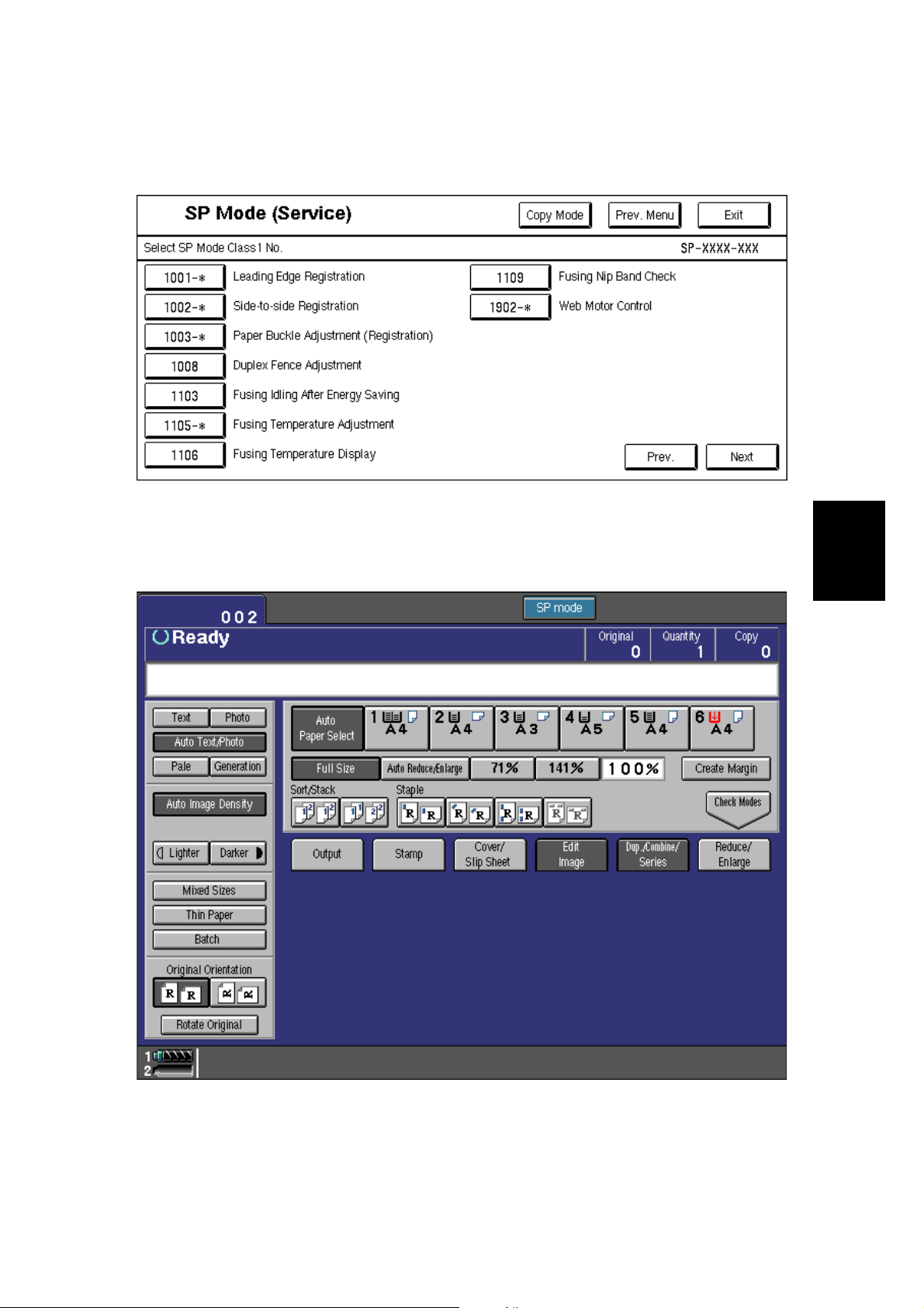
Accessing Copy Mode from within an SP Mode
1) Touch the “Copy Mode” key.
A294M003.PCX
2) Select the appropriate copy mode and make trial copies.
3) To return to the SP mode, touch the “SP mode” key.
Tables
Service
4-7
A294M004.PCX
Page 18
SERVICE PROGRAM MODE 18 July, 2001
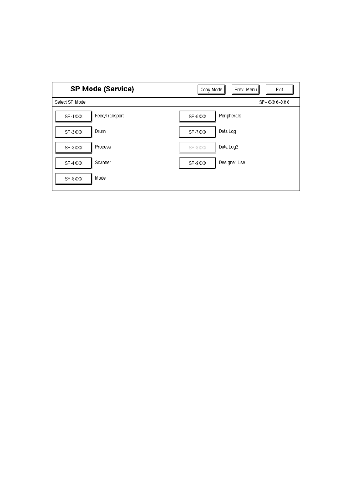
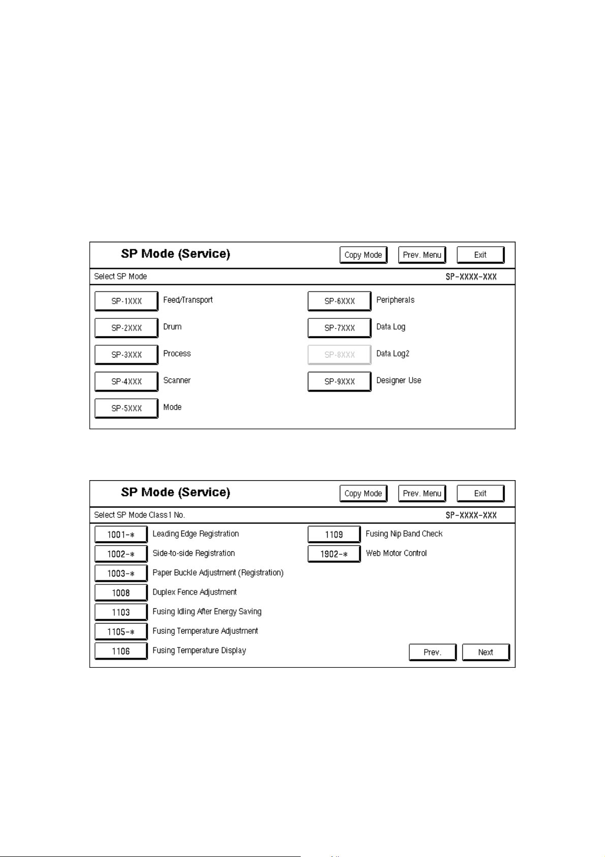
Selecting the Program Number
Program numbers are composed of two or three levels.
There are two ways to select the program number.
Ten-key Pad
Input the required program number.
Touch Panel
1) Touch the 1st level program.
2) Touch the 2nd level program.
NOTE: A “*” mark indicates that there are 3rd level programs.
3) Touch the 3rd level program.
A294M002.PCX
A294M003.PCX
4-8
Page 19
18 July, 2001 SERVICE PROGRAM MODE
A294M005.PCX
Tables
Service
4-9
Page 20

SERVICE PROGRAM MODE 18 July, 2001
Inputting a Value or Setting for an SP Mode
1. Select the required program mode as explained on the previous page.
2. Enter the required setting using the ten-key pad, then touch the “Start” key or
OK key or $ key.
NOTE: 1) If you forget to touch the “Start” key or OK key, the previous value
remains.
2) Change between “+” and “–” using the “•” key before entering the
required value.
3. Exit SP mode.
4-10
Page 21
18 July, 2001 SERVICE PROGRAM MODE
4.2.2 SERVICE PROGRAM MODE TABLES
NOTE: 1) In the Function column, comments are in italics.
2) In the Settings column, the default value is in bold letters.
3) S and B in the right hand side of the mode number column means that
this mode is stored in the NVRAM on the SICU (S) or BCU (B). If you do
a RAM reset, all these SP modes will be reset to their factory settings.
4) [A294 I], [A295 I], [A294 II] and [A295 II] in the Settings column mean
the following product types:
[A294 I]: Existing 85 cpm model. [A295 I]: Existing 105 cpm model.
[A294 II]: Enhanced 85 cpm model. [A295 II]: Enhanced 105 cpm
model.
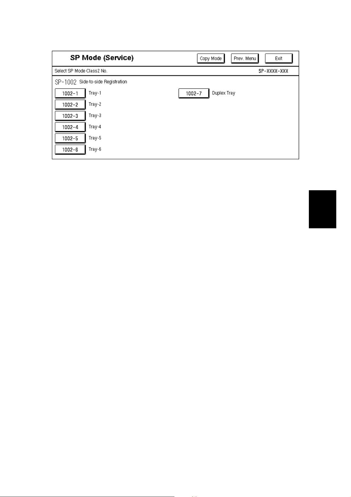
1-001
1-002
Mode No.
(Class 1, 2 and 3)
Leading Edge Registration
Paper Tray
1
(Copier and
LCT)
2 Duplex Tray
Side-to-Side Registration
1Tray-1
2Tray-2
Function Settings
Adjusts the printing leading edge
registration for feeding from the trays using
the trimming area pattern (SP2-902-3,
No.15).
B
Use the “
before entering the value.
The specification is 3
See "Replacement and Adjust m ent – Copy
Image Adjustments" for details.
Adjusts the printing leading edge
registration for the duplex feeding using the
trimming area pattern (SP2-902-3, No.15).
Use the “
before entering the value.
B
The specification is 3
See "Replacement and Adjust m ent – Copy
Image Adjustments" for details.
Adjusts the printing side-to-side registration
from the 1st paper feed station using the
trimming area pattern (SP2-902-3, No.15).
B
Use the “
before entering the value.
See “Replacement and Adjustment – Copy
Image Adjustments” for details on SP1-002.
Adjusts the printing side-to-side registration
from the 2nd paper feed station using the
trimming area pattern (SP2-902-3, No.15).
Use the “
before entering the value.
B
The specification is 0
•
” key to toggle between + and –
±
2 mm.
•
” key to toggle between + and –
±
2 mm.
•
” key to toggle between + and –
•
” key to toggle between + and –
±
2.0 mm.
+9 ~ –9
0.1 mm/step
+3.0 mm
+9 ~ –9
0.1 mm/step
–1.5 mm
+9 ~ –9
0.1 mm/step
–1.5 mm
Tables
Service
4-11
Page 22
SERVICE PROGRAM MODE 18 July, 2001
1-002
1-003
Mode No.
(Class 1, 2 and 3)
Side-to-Side Registration
3Tray-3
4 Tray-4 (LCT)
5 Tray-5 (LCT)
6 Tray-6 (LCT)
7 Duplex Tray
Paper Buckle Adjustment (Registration)
1 Copier Paper
Tray
2LCT Tray
3 Duplex Tray B
Duplex Fence Adjustment1-008
Fusing Idling After Low Power Mode1-103
Adjusts the printing side-to-side registration
from the 3rd paper feed station using the
trimming area pattern (SP2-902-3, No.15).
Use the “
B
before entering the value.
The specification is 0
Adjusts the printing side-to-side registration
from the 4th paper feed station using the
trimming area pattern (SP2-902-3, No.15).
B
Use the “
before entering the value.
The specification is 0
Adjusts the printing side-to-side registration
from the 5th paper station using the
trimming area pattern (SP2-902-3, No.15).
B
Use the “
before entering the value.
The specification is 0
Adjusts the printing side-to-side registration
from the 6th paper station using the
trimming area pattern (SP2-902-3, No.15).
B
Use the “
before entering the value.
The specification is 0
Adjusts the printing side-to-side registration
from the duplex tray using the trimming
area pattern (SP2-902-3, No.15).
B
Use the “
before entering the value.
The specification is 0
Adjusts the relay clutch timing at
B
registration. The relay clutch timing
determines the amount of paper buckle at
B
registration. (A +ve setting leads to more
buckling.)
Adjusts the distance between the front and
B
rear fences.
Selects whether fusing idling is done or not
when recovering from the low power mode.
Function Settings
•
” key to toggle between + and –
±
2.0 mm.
•
” key to toggle between + and –
±
2.0 mm.
•
” key to toggle between + and –
±
2.0 mm.
•
” key to toggle between + and –
±
2.0 mm.
•
” key to toggle between + and –
±
2.0 mm.
+9 ~ –9
0.1 mm/step
–1.5 mm
+9 ~ –9
0.1 mm/step
–2.5 mm
+9 ~ –9
0.1 mm/step
–2.5 mm
+9 ~ –9
0.1 mm/step
–2.5 mm
+9 ~ –9
0.1 mm/step
–3.0 mm
+9 ~ –9
1 mm/step
+4.0 mm
+4 ~ –4
0.5 mm/step
0.0 mm
0: Not done
1: Done
B
4-12
Page 23

18 July, 2001 SERVICE PROGRAM MODE
1-105
Mode No.
(Class 1, 2 and 3)
Fusing Temperature Adjustment
Fusing
1
Temperature in
Waiting
Condition
2Fusing
Temperature
Lower Limit
3Fusing
Temperature
Correction
(<A4/LT)
4Fusing
Temperature
Correction
(A4/LT)
Fusing Temperature Display1-106
Fusing Nip Band Check1-109
Web Motor Control1-902
1Web
Consumption
Adjusts the fusing temperature for standby.
B
Adjusts the fusing temperature lower limit.
When the fusing unit falls below this
temperature, the machine stops copying.
Copying automatically restarts when the
B
fusing temperature recovers.
This SP mode is for designer’s use only.
Specifies the amount to raise the fusing
temperature from standby mode to print on
A4/LT or smaller width paper.
B
Specifies the amount to raise the fusing
temperature from standby mode to print on
paper of A4/LT width.
B
Displays the fusing temperature.
Feeds a sheet from a paper tray and stops
the sheet when it is between the hot roller
and the pressure roller. Use an OHP sheet.
After keeping the sheet there for 30
seconds, the sheet is automatically fed out.
For details, see Replacement and
Adjustment – Fusing.
Displays the percentage of the web
consumption in 1% steps (0% ~ 107%).
The value can be manually input using
B
number keys.
Function Settings
[A294 I & II]
168 ~ 178
1°C/step
173°°°°C
[A295 I & II]
173 ~ 178
1°C/step
178°°°°C
[A294 I & II]
157 ~ 163
1°C/step
163°°°°C
[A295 I & II]
157 ~ 167
1°C/step
167°°°°C
+0 ~ +20
1°C/step
[A294 I & II]
+15°°°°C
[A295 I & II]
+20°°°°C
–5 ~ +20
1°C/step
[A294 I]
+10°°°°C
[A295 I]
+15°°°°C
[A294 II]
+5°°°°C (US)
+10°°°°C (EU)
[A295 II]
+5°°°°C (US)
+15°°°°C (EU)
Tables
Service
4-13
Page 24
SERVICE PROGRAM MODE 18 July, 2001
1-902
2-001
Mode No.
(Class 1, 2 and 3)
Web Motor Control
Web Motor
2
Drive Interval
Web Motor
3
Drive Time
Web Near End
4
Setting
Duplex Stop Position – Right1-906
Charge Corona Bias Adjustm ent
1 Image Area
(Auto Process
Control OFF)
2 ID Sensor
Pattern (Auto
Process Control
OFF)
Change the interval of copy operation time
after which the web motor is driven
B
Changes the time that the web motor is
driven.
B
Changes the web consumption ratio at
which web near end is displayed.
About 40k A4 copies can be made after the
B
web consumption reaches 100%.
Changes the paper stop position in the
duplex unit after passing duplex transport
B
sensor 2.
For designer use only.
Adjusts the voltage applied to the grid plate
during copying when auto process control
is off.
Normally, there is no need to adjust this.
B
If there is an ID or TD sensor problem, the
machine goes into fixed toner supply mode.
After replacing the drum or charge corona
wire, change this value to the default.
Adjusts the voltage applied to the grid plate
when making the ID sensor pattern, when
auto process control is switched off.
Normally, there is no need to adjust this.
If the user wants high density copies, the
B
sensor pattern must be lighter, so this
voltage must be a higher negative voltage.
Function Settings
[A294/A295 I]
15 ~ 130
1 s/step
[A294 I] 42 s
[A295 I] 34 s
[A294/A295 II]
3 ~ 130
1 s/step
[A294 II]
11 s (EU)
21 s (US)
[A295 II]
9 s (EU)
17 s (US)
[A294/A295 I]
0.1 ~ 3.0
0.1 s/step
0.8 s
[A294/A295 II]
0.3 ~ 3.5
0.1 s/step
2.8 s
0 ~ 105
1%/step
[A294/A295 I]
100%
[A294/A295 II]
86% (EU)
90% (US)
–10 ~ 10
2 mm/step
–8 mm
–600 ~ –1,300
10 V/step
–1,000 V
–600 ~ –1,300
10 V/step
–800 V
4-14
Page 25
18 July, 2001 SERVICE PROGRAM MODE
2-001
2-101
Mode No.
(Class 1, 2 and 3)
Charge Corona Bias Adjustm ent
Image Area
3
(Auto Process
Control ON)
Adjusts the voltage applied to the grid plate
during copying when auto process control
is switched on.
B
This voltage changes every time auto
process control starts up (every time the
machine is switched on)
4 Grid Voltage for
Transparent
Sheet
Adjusts the voltage applied to the grid plate
when translucent mode is selected.
Use this if there is a copy quality problem
B
when making copies on translucent paper.
Normally there is no need to adjust this.
See 2-001-1.
5 Total Corona
Current
Total Corona
6
Current (Photo
mode)
D
7V
(Auto
Process
Control)
Adjusts the current applied to the charge
corona wire except for Photo mode.
B
Adjusts the current applied to the charge
corona wire for Photo mode.
B
Adjusts the target V
Control Initial Setting.
B
Printing Erase Margin
Adjusts the leading edge erase margin.1 Leading Edge
See “Replacement and Adjustment – Copy
S
Image Adjustments” for more on SP2-101.
Function Settings
–600 ~ –1,300
10 V/step
[A294/A295 I]
–1,000 V
[A294/A295 II]
–950 V
–600 ~ –1,300
10 V/step
[A294/A295 I]
–1,070 V
[A294/A295 II]
–950 V
–1,400 ~
–2,800
100µA/step
–1,400 µµµµA
1,400 ~
–2,800
100µA/step
–1,600 µµµµA
D
voltage for Process
–800 ~ –1,000
10 V/step
[A294/A295 I]
–970 V
[A294/A295 II]
–850 V
0.0 ~ 9.0
0.1 mm/step
2.5 mm
Tables
Service
2-103
4Right
LD Power Adjustment
2 LD2 - 600dpi
Adjusts the trailing edge erase margin.2 Trailing Edge
S
Adjusts the left side erase margin.3 Left
S
Adjusts the right side erase margin.
S
Adjusts the power of LD1.1 LD1 - 600dpi
Do not change the value.
B
Adjusts the power of LD2.
Do not change the value.
B
4-15
0.0 ~ 9.0
0.1 mm/step
2.5 mm
0.0 ~ 9.0
0.1 mm/step
2.0 mm
0.0 ~ 9.0
0.1 mm/step
2.0 mm
–127 ~ +127
1/step
1 = 1.1 µW
+0
–127 ~ +127
1/step
1 = 1.1 µW
+0
Page 26
SERVICE PROGRAM MODE 18 July, 2001
2-103
2-114
2-201
Mode No.
(Class 1, 2 and 3)
LD Power Adjustment
Adjusts the power of LD3.3 LD3 - 600dpi
Do not change the value.
B
Adjusts the power of LD4.4 LD4 - 600dpi
Do not change the value.
B
LD1 Power
5
Adjustment
(Start/End)
LD2 Power
6
Adjustment
(Start/End)
LD3 Power
7
Adjustment
(Start/End)
LD4 Power
8
Adjustment
(Start/End)
LD Power Adjustment (for ID pattern)2-104
Printer Dot Edge Parameter Setti ng
1 Leading Dot
Level Setting
(Left Edge)
2 Trailing Dot
Level Setting
(Right Edge)
3 Multiple Dot
Level Setting S
4 Independent
Dot Level
Setting
Development Bias Adjustment
2 ID Sensor
Pattern
Factory use only. Do not use this SP
B
mode.
Factory use only. Do not use this SP
B
mode.
Factory use only. Do not use this SP
B
mode.
Factory use only. Do not use this SP
B
mode.
Selects the LD power for making the ID
pattern when auto process control is
B
switched on. Do not use unless advised.
Changes the LD power level for the left
S
edge pixel in printer mode, if FCI is off.
Changes the LD power level for the left
S
edge pixel in printer mode, if FCI is off.
Changes the LD power level for continuous
pixels in printer mode, if FCI is off.
Changes the LD power level for
S
independent dots in printer mode, if FCI is
off.
Adjusts the development bias for copying.1 Image Area
This can be adjusted as a temporary
measure if faint copies appear due to an
B
aging drum.
Adjusts the development bias for making
the ID sensor pattern for V
when the auto process control is set to off.
This should not be used in the field,
B
because it affects ID sensor pattern
density, which affects toner supply.
Function Settings
–127 ~ +127
1/step
1 = 1.1 µW
+0
–127 ~ +127
1/step
1 = 1.1 µW
+0
Start
Stop
Start
Stop
Start
Stop
Start
Stop
0 ~ 7
1/step
4
20 ~ 100%
1% step
50%
20 ~ 100%
1% step
50%
20 ~ 100%
1% step
100%
20 ~ 100%
1% step
50%
–200 ~ –700
10 V/step
[A294/A295 I]
–530 V
[A294/A295 II]
–650 V
–200 ~ –700
SP
measurement
10 V/step
–400 V
4-16
Page 27
18 July, 2001 SERVICE PROGRAM MODE
2-201
2-207
2-208
2-209
2-210
Mode No.
(Class 1, 2 and 3)
Development Bias Adjustment
Transparent
3
Sheet
B
4 ID Sensor
Development
Potential
B
Forced Toner Supply
1 Forced Toner
Supply
2 Toner Bank
Toner Setup
Toner Supply Mode
B
Toner Supply Rate
B
ID Sensor Pattern Interval
Function Settings
Adjusts the development bias for copying
onto translucent sheets.
Adjusts the development potential for
making the ID sensor pattern for V
SP
measurement when the auto process
control is set on.
Forces toner supply for 7 seconds from the
toner bank through the toner hopper to the
development unit.
This mode finishes automatically after the
toner is supplied 7 times (1 s for each
time).
Turns on the main motor, development
motor, development bias, toner supply
motor and charge corona. Then turns on
the toner supply coil clutch to supply toner
to the toner hopper, but not to the
development unit. It takes about 7 minutes.
This mode should be used to fill the toner
transport path with toner after cleaning the
toner supply unit, or at installation.
Selects the toner supply mode.
Use image pixel count mode only as a
temporary countermeasure if the ID or TD
sensor is defective.
Adjusts the toner supply rate from the
hopper.
Increasing this value reduces the toner
supply roller clutch on time. Use a lower
value if the user tends to make lots of
copies that have a high proportion of black.
Changes the interval for making the ID
sensor pattern (V
SP/VSG
detection).
If the user normally makes copies with a
high proportion of black, reduce the
interval.
–200 ~ –700
10 V/step
[A294/A295 I]
–530 V
[A294/A295 II]
–650 V
180 ~ 380
1 V/step
280 V
Start
Start
Sensor
Control
Pixel Count
Control
100 ~ 2,000
10 mg/s/step
[A294 I & II]
800 mg/s
[A295 I & II]
1000 mg/s
0 ~ 500
1 copy/step
10 copies
Tables
Service
B
4-17
Page 28
SERVICE PROGRAM MODE 18 July, 2001
2-220
2-301
Mode No.
(Class 1, 2 and 3)
REF
V
Manual Setting
B
VT Display2-223
B
Toner Bank Toner Discharge2-226
Toner Supply Mode Display2-227
Transfer Current Adjustment
11st Copy Side
B
Function Settings
Adjusts the TD sensor reference voltage
REF
(V
).
Change this value after replacing the
development unit with another one that
already contains toner.
For example, when using a development
unit from another machine for test
purposes, do the following:
1. Check the value of SP2-220 in both the
machine containing the test unit and the
machine that you are going to move it to.
2. Install the test development unit, then
input the V
for this unit into SP2-220.
REF
3. After the test, put back the old
development unit, and change SP2-220
back to the original value.
Displays the current TD sensor output
voltage.
This SP removes toner from the toner bank
to the toner hopper.
After turning the toner supply motor and the
toner bank motor on, the toner supply coil
clutch turns on and off at 2 second
intervals. The motors and clutch stop when
the toner near-end sensor (in the toner
bank unit) detects no toner.
Even if the sensor continues to detect
toner, this operation stops when the clutch
has been turned on and off 10 times, so
this SP may have to be repeated to clean
out the system completely.
Displays the toner supply mode used for
the last copy.
1: ID Sensor and TD Sensor (from the 11th
copy, using V
T
– V
REF
)
2: ID Sensor and TD Sensor (using
SP/VSG
V
) – before the 10th copy of a job
3: TD Sensor – temporary mode when ID
sensor output is abnormal
4: Image Pixel Count
Adjusts the current applied to the transfer
belt during copying on the 1st side of the
paper.
If the user uses thicker paper, the current
may have to be increased to ensure
sufficient transfer of toner.
0 ~ 5.0
0.01 V/step
2.5 V
Start
10 ~ 200
1 µA/step
[A294 I & II]
120 µµµµA
[A295 I & II]
140 µµµµA
4-18
Page 29
18 July, 2001 SERVICE PROGRAM MODE
2-301
2-506
2-801
Mode No.
(Class 1, 2 and 3)
Transfer Current Adjustment
2 Thick Paper
3 OHP Sheet
4 Transparent
Paper
5 2nd Copy
6 Between Pages
Cleaning Interval – Multiple Copy
1On/Off
2 Interval
TD Sensor Initial Setting
Adjusts the current applied to the transfer
belt during copying on thick paper.
See above.
B
Adjusts the current applied to the transfer
belt during copying on OHP sheet.
B
See above. If the user normally feeds
thicker paper from the bypass tray, use a
higher setting.
Adjusts the current applied to the transfer
belt during copying on translucent paper.
B
Adjusts the current applied to the transfer
belt during copying on the 2nd side of the
paper.
B
Adjusts the current applied to the transfer
belt between the pages.
B
Selects whether multiple copy jobs are
stopped at regular intervals for the following
purposes.
1. Stop and turn the drum motor in reverse
2. Make an ID sensor pattern to correct the
B
The interval depends on SP2-506-2.
Use if the drum gets dirty or images get too
pale or too dark during a long job.
Normally keep at ‘No’, because the ‘Yes’
setting causes the machine to stop copying
every 15 minutes, which may cause
problems for the customer.
Selects the interval at which multi copy jobs
are stopped.
B
Performs the TD sensor initial setting. This
SP mode controls the voltage applied to the
TD sensor to make the TD sensor output
about 2.5 V. After finishing this, the TD
B
sensor output voltage is disp layed.
Use this mode only after changing the TD
sensor or the developer.
Function Settings
to clean the cleaning blade edge
toner density control.
10 ~ 200
1 µA/step
[A294 I & II]
120 µµµµA
[A295 I & II]
140 µµµµA
10 ~ 200
1 µA/step
140 µµµµA
10 ~ 200
1 µA/step
[A294 I & II]
120 µµµµA
[A295 I & II]
140 µµµµA
10 ~ 200
1 µA/step
[A294 I & II]
120 µµµµA
[A295 I & II]
140 µµµµA
10 ~ 200
1 µA/step
20 µµµµA
1: No
2: Yes
1 ~ 100
1 minute/step
30 minutes
Start
Tables
Service
4-19
Page 30
SERVICE PROGRAM MODE 18 July, 2001
2-803
2-804
2-813
2-902
2-909
Mode No.
(Class 1, 2 and 3)
Corona Wire Cleaner On
Turns on the corona wire cleaner manually.
When copy density across the paper is
uneven at EM, clean the wire with this
mode.
Charge Corona Cleaner Setting
1 Corona Wire
Cleaner
Operation
Setting
2 Operation
Interval B
Printer Gamma Setting
Printing Test Pattern
2IPU Test
Pattern
Selection
(for Scanner)
3 Printing Test
Pattern
4 Outer I/F Block
Test Pattern
Frequency
5
Pattern Density
Vcont Manual Setting2-906
Main Scan Magnification
1 Copier
Selects when automatic corona wire
cleaning is done.
0: Corona wire cleaning is not done.
1: When process control initial setting is
B
2: At the period set in SP2-804-2.
Selects the interval for automatic corona
wire cleaning.
Select if printer gamma correction is
applied or not.
S
This SP mode is for designer use only.
Prints the test patterns for the IPU chip.
See section 4.2.3. for how to print test
patterns.
This SP mode is useful for finding whether
the SICU or the SBU is defective. If the
printout is not OK, the SICU is defective.
Prints the printer test patterns.
See section 4.2.3. for how to print test
patterns.
Example: 15. Trimming Area
This SP mode is useful for finding whether
the LDDR or the SICU is defective. If the
printout is not OK, the LDDR is defective.
Prints the test patterns for the IPU chip.
See section 4.2.3. for how to print test
patterns.
This SP mode is useful for finding whether
the SICU or the printer application is
defective. If the printout is not OK, the
SICU is defective.
Designer use only.
B Factory use only.
Adjusts the magnification in the main scan
direction for copy mode.
Use the “
S
See “Replacement and Adjustment – Copy
Image Adjustments” for details.
Function Settings
done, if the copy number after the last
cleaning operation is over the number
set in SP2-804-2.
•
” key to toggle between + and –.
Start
[A294/A295 I]
0: Not done
1: Done
2:Periodically
[A294/A295 II]
0: Not done
1: Done
2:Periodically
100 ~ 10,000
100 print/step
5,000
0: Applied
1: Not applied
9.7 V
–2.0 ~ +2.0
0.1%/step
+0.0%
4-20
Page 31

18 July, 2001 SERVICE PROGRAM MODE
2-909
2-910
2-911
2-913
2-920
2-940
Mode No.
(Class 1, 2 and 3)
Main Scan Magnification
2 Printer
Writing Sub Scan Magnification
Transfer Current On/Off Timing
1 La (ON)
2 Lb (On/Off
exchange
timing)
3 Lc (OFF)
Drum Reverse Rotation Interval2-912
Test Pattern ID Adjustment
LD Off Check
Transfer Pre-cleaning2-930
Leading Edge Transfer Current Adjustment
1Tray-1
2Tray-2
3Tray-3
4 Tray-4 (LCT)
5 Tray-5 (LCT)
6 Tray-6 (LCT)
7 Duplex Tray
Adjusts the magnification in the main scan
direction when printing from a personal
computer.
S
Use the “
See “Replacement and Adjustment – Copy
Image Adjustments” for details.
Adjusts the magnification in the sub scan
direction.
S
Use the “
See "Replacement and Adjust m ent – Copy
Image Adjustments" for details.
Adjusts the transfer current on timing at the
B
leading edge.
Adjusts the transfer current on/off
exchange timing.
B
(A294/A295 II models only)
Adjusts the transfer current off timing
B
(for example: –5 mm is 5 mm after the
trailing edge).
This SP mode is for designer use only.
Do not change the value.
B
Adjusts the image density for printing test
patterns (with SP2-902). Usually this SP
mode is only used by designers.
The value is cleared when the main power
switch is turned off and on.
Checks whether the LD turns off or on
when the front door is opened.
0: On 1: Off
Factory use only.
Designer use only
Adjusts the leading edge transfer current
for each paper feed station.
(A294/A295 II models only)
B
•
” key to toggle between + and –.
•
” key to toggle between + and –.
Function Settings
–2.0 ~ +2.0
0.1%/step
+0.0%
–1.0 ~ +1.0
0.1%/step
+0.0%
–30 ~ +30
1 mm/step
0 mm
[A294/A295 II]
0 ~ +60
1 mm/step
+45 mm
–30 ~ +30
1 mm/step
0 mm
0 ~ 10
1/step
2
0 ~ 15
1/step
15
0: ON
1: OFF
10 ~ 200
1 µA/step
[A294 II]
120 µµµµA
[A295 II]
140 µµµµA
Tables
Service
4-21
Page 32

SERVICE PROGRAM MODE 18 July, 2001
2-941
2-962
Mode No.
(Class 1, 2 and 3)
Transfer Current for Semi-thick Paper
Determines that the transfer current for
semi-thick paper is handled as Plain paper
or Thick paper
• Setting this mode to “Thick paper” is
effective when image at the leading edge
is not good.
• To use this mode, “Recycled paper”
B
should be selected in the User Tools for
semi-thick paper.
• Selecting “Thick paper” in the User Tools
is the same effect as this mode. But
selecting “Thick paper” in the User Tools
does not allow the duplex or punch
mode.
Developer Initialization (Factory)2-961
Factory use only.
Auto Process Control
Automatically adjusts the following process
control factors.
1. Drum potential sensor
2. ID sensor
3. Charge grid voltage (by changing V
4. LD power (by changing V
B
Before using this SP, auto process control
should be on (SP3-901).
After changing the drum, ID sensor, drum
potential sensor, LD unit, charge corona
wires, or toner density sensor, this SP
should be used.
Periodical Auto Process Control2-966
Selects whether auto process control is
done after the first job since 24 hours is
finished. This setting is required for a
B
customer who keeps the main switch on all
day.
Function Settings
0: Plain paper
1: Thick paper
Start
D
)
H
)
ON
OFF
2-967
Auto Image Density Adjustment
Selects whether auto image de nsity
adjustment is done during machine warm
up. This mode is to counter dirty
background that occurs when a machine is
used in an area that contains ammonia.
If Periodical Auto Process Control (SP2-
966) is used, this adjustment is done also
after the auto process control is finished.
B
OFF
ON
4-22
Page 33

18 July, 2001 SERVICE PROGRAM MODE
2-971
2-972
2-973
Mode No.
(Class 1, 2 and 3)
Function Settings
Toner Density Correction2-968
To prevent the image density dropping
during continuous copying after a long
interval (this is caused by a sudden
increase of Q/M), V
0.06 V every (100 X (SP2-974 value + 1))
B
REF
is changed by –
0 ~ 20 k
1 k prints/step
0
prints. This correction is applied from when
the auto process control is done, until “(the
number of prints set in this SP mode) X
(SP2-974 value +1)” has been made.
ID Sensor Pattern Interval – Multicopy2-969
Twenty ID patterns are made in a 1-minute
interval during a continuous copy process
just after the process control is completed.
B
OFF
ON
Image density will be stabilized. However,
the printing productivity will be decreased.
Toner Suction System2-970
Displays whether the toner suction system
is installed in order to distinguish between
A294/A295 I and A294/A295 II.
[A294/A295 I]
0: Not installed
[A294/A295 II]
1: Installed
Collected Toner Level Check
Check this mode when “Waste toner full” pop-up message comes up or “Near full”
message is displayed.
1 Left Toner
Collection Bottle
2 Toner
Collection Bottle
3 Toner Suction
Motor
Display whether the used toner collection
bottle is full or not.
Display whether the sucked toner collection
bottle is full or not.
(A294/A295 II models only)
Displays whether the toner suction motor
needs to be replaced or not.
(A294/A295 II models only)
0: Not full
2: Full
0: Not full
1: Near full
2: Full
0: Not needed
1: Needed
soon
2: Needed
Sucked Toner Collection Bottle Operation Time
Displays the total operation time of the
XXX hours
toner suction motor to maintain the sucked
toner collection bottle replacement.
<Preset Values>
B
Near full: 280 hours, Full: 300 hours
Reset the value to 0 (zero) by pressing 0
and # (Enter) keys when the bottle is
replaced.
Toner Suction Motor Operation Time
Displays the total operation time of the
XXX hours
toner suction motor to maintain the toner
suction motor replacement.
<Preset Values>
Near full: 570 hours, Full: 600 hours
B
Reset the value to 0 (zero) by pressing 0
and # (Enter) keys when the bottle is
replaced.
Tables
Service
4-23
Page 34

SERVICE PROGRAM MODE 18 July, 2001
2-974
3-001
3-001
3-103
3-902
Mode No.
(Class 1, 2 and 3)
Toner Supply Interval
ID Sensor Initial Setting
1 ID Sensor PWM
Setting
B
ID Sensor Initial Setting
2 Initialization
B This SP mode should be performed after:
ID Sensor Output Display
SG
1V
2VSG Initial
(Designer Use)
SP
3V
SP
4V
Initial
B
(Designer Use)
Auto Process Control Setting3-901
B
Process Control Data Display3-902
1 Auto Process
Control
B
(O: OFF, 1: ON)
Process Control Data Display
D
2V
3 Half Tone V
B Displays the drum potential.
H
B
G
4V
B
Function Settings
Adjusts the interval of toner supply. (Once
every how many prints)
• The operation of SP2-968 has been
changed.
• The V
update interval has been
REF
changed from “every 100 prints” to
“every (100 X (SP2-974 value + 1))
prints”.
This SP mode is added to recover the
machine when an SC condition occurs
because ID Sensor Initial Setting is not
done after doing an NVRAM Clear or
replacing the NVRAM. Reset this SP to the
factory setting in this case.
The PWM data is stored when ID Sensor
Initial Setting is done.
Performs the ID sensor initial setting. The
ID sensor output for the bare drum (V
SG
) is
adjusted to 4.0 ± 0.2 V.
1. Replacing or cleaning the ID sensor
2. Replacing the NVRAM or doing an
NVRAM clear.
Displays the current VSG and VSP output.
If the ID sensor does not detect the ID
pattern, “V
= 5.0 V/VSG = 5.0 V” is
SP
displayed and an SC code is generated.
If the ID sensor does not detect the bare
area of the drum, “V
SP = 0.0 V/VSG = 0.0 V”
is displayed and an SC code is generated.
Decides whether or not the machine
checks and corrects the drum potential
(V
D
) and LD power when the fusing
temperature is lower than 100°C at powerup.
Displays whether auto process control is on
or off.
Displays the drum potential in areas
illuminated by the laser during LD power
adjustment (auto process control).
Displays the charge grid voltage which
D
resulted from the latest V
adjustment.
0: 1/1 (every
print)
1: 1/2 (every 2
prints)
2: 1/3 (every 3
prints)
3: 1/4 (every 4
prints)
0 ~ 255
1/step
72
Start
ON
OFF
4-24
Page 35

18 July, 2001 SERVICE PROGRAM MODE
3-902
3-903
4-008
4-010
4-011
Mode No.
(Class 1, 2 and 3)
Process Control Data Display
LD Power
5
(Correction)
Displays the LD power correction value
which resulted from the latest V
B
adjustment.
6VID
7VM200
Displays the latest drum surface voltage
measured on the ID sensor pattern.
B
Displays the drum potential sensor output
when 200 V is applied during potential
B
sensor correction.
8VM700
Displays the drum potential sensor output
when 700 V is applied during potential
B
sensor correction.
D
9V
Correction
Displays whether the V
performed. The target value of the V
B
correction is “SP2-001-7 value + 50”.
(A294/A295 II models only)
VD Correction Counter
Adjusts the starting point for the V
Correction.
Displays whether the V
performed. The target value of the V
correction is “SP2-001-7 value + 50”.
B
(A294/A295 II models only)
The counter to control the V
automatically reset to 0 (zero) when
SP2-801 is performed.
Scanner Sub Scan Magnif icati on
Adjusts the magnification in the sub scan
direction for scanning.
If this value is changed, the scanner motor
speed is changed.
S
Use the “
See “Replacement and Adjustment – Copy
Image Adjustments” for details.
Scanner Side-to-Side Registration
Adjusts the leading edge registration for
scanning.
(–): The image moves in the direction of the
S
Use the “
See “Replacement and Adjustment – Copy
Image Adjustments" for details.
Scanner Side-to-Side Registration
Adjusts the side-to-side registration for
scanning.
(–): The image disappears at the left side.
(+): The image appears at the left side.
S
Use the “
See “Replacement and Adjustment – Copy
Image Adjustments” for details.
Function Settings
D
correction is being
D
correction is being
D
•
” key to toggle between + and –.
leading edge
•
” key to toggle between + and –.
•
” key to toggle between + and –.
H
D
D
D
correction is
0: Not
performed
1: Performed
0 ~ 999
1 k prints/step
100 k prints
–0.9 ~ +0.9
0.1 %/step
+0.0 %
–9.0 ~ +9.0
0.1 mm/step
+0.0 mm
–6.0 ~ +6.0
0.1 mm/step
+0.0 mm
Tables
Service
4-25
Page 36

SERVICE PROGRAM MODE 18 July, 2001
4-012
4-015
4-303
4-428
Mode No.
(Class 1, 2 and 3)
Scanner Erase Margin
1 Leading Edge
Adjusts the leading edge erase margin for
scanning.
S
Do not adjust this unless the user wishes to
have a scanner margin that is greater than
the printer margin.
2 Trailing Edge
Adjusts the trailing edge erase margin for
scanning.
S
See the comment for SP4-012-1.
3Right
Adjusts the right side erase margin for
scanning.
S
See the comment for SP4-012-1.
4 Left
Adjusts the left side erase margin for
scanning.
S
See the comment for SP4-012-1.
Scanner Free Run4-013
Performs a scanner free run with the
exposure lamp on.
Scanner Speed Adjustment
Displays the value of the scanner speed
fine adjustment. This setting can be
changed using the number keys.
S
The scanner speed fine adjustment is
automatically done when the main switch is
turned on, and the current setting is
overwritten.
APS Sensor Output Display4-301
Displays the APS sensor output signals
when an original is placed on the exposure
glass
APS A5/HLT Size Original Detection
Selects whether or not the copier
determines that the original is A5/HLT size
when the APS sensor does not detect the
size.
If “A5 length/5
sizes that cannot be detected by the APS
sensors are regarded as A5 lengthwise or
S
5
" x 8
1/2
If “Not detected” is selected, “Cannot detect
original size” will be displayed.
Scanner Adjustment
1 Flag Display
2 Standard
Displays whether or not the standard white
S
level adjustment has been done.
Corrects the standard white level from the
white plate.
This SP mode is for factory use only. Do
not use this SP mode.
Function Settings
1/2" x 81/2"” is selected, paper
".
1/2
0.0 ~ 0.9
0.1 mm/step
0.5 mm
0.0 ~ 0.9
0.1 mm/step
0.5 mm
0.0 ~ 0.9
0.1 mm/step
0.5 mm
0.0 ~ 0.9
0.1 mm/step
0.5 mm
0: Stop
1: Start
–20 ~ +20
1/step
0
0: Not
detected
1: A5 length/
5
1/2
" x 8
1/2
2: Not
detected
3: A5 length/
1/2
5
" x 8
1/2
(Setting 2 or
3 is required
if 267 x 390
and 267 x
195 paper is
used.)
Adjusted
Not adjusted
Start
"
"
4-26
Page 37

18 July, 2001 SERVICE PROGRAM MODE
4-902
Mode No.
(Class 1, 2 and 3)
SBU Setting
Image data
Path Setting
E/O
3
Adjustment First Side
4E/O
Adjustment Last Side
7 Black Level -
First Side
8 Black Level -
Last Side
15 Range
Adjustment First Side
16 Gain Range
Adjustment Last Side
Gain
19
Adjustment First Side E-ch
Gain
20
Adjustment First Side O-ch
Gain
21
Adjustment Last Side E-ch
Function Settings
Changes the image data path in the SBU.1
S
This SP mode is for factory use only. Do
not use this SP mode.
Displays the ASIC ID of the SBU.2 ASIC ID Display
This SP mode is for factory use only.
Checks the difference value of the black
level for the first side after adjusting the
black level at power-up.
S
This SP mode is for designer use only.
Do not use this SP mode.
Checks the difference value of the black
level for the last side after adjusting the
black level at power-up.
S
This SP mode is for designer use only.
Do not use this SP mode.
Checks the value of the black level for the
first side after adjusting the black level at
power-up.
S
This SP mode is for designer use only.
Do not use this SP mode.
Checks the value of the black level for the
last side after adjusting the black level at
power-up.
S
This SP mode is for designer use only.
Do not use this SP mode.
Checks the AGC gain range of the white
level for the first side after adjusting the
white level at power-up.
S
This SP mode is for designer use only.
Do not use this SP mode.
Checks the AGC gain value of the white
level for the last side after adjusting the
white level at power-up.
S
This SP mode is for designer use only.
Do not use this SP mode.
Checks the AGC gain value of the white
level for the EVEN channel of the first side
after adjusting the white level at power-up.
S
This SP mode is for designer use only.
Do not use this SP mode.
Checks the AGC gain value of the white
level for the ODD channel of the first side
after adjusting the white level at power-up.
S
This SP mode is for designer use only.
Do not use this SP mode.
Checks the AGC gain value of the white
level for the EVEN channel of the last side
after adjusting the white level at power-up.
This SP mode is for designer use only.
S
Do not use this SP mode.
0 ~5
1/step
0
0 ~ 255
1/step
128
0 ~ 255
1/step
128
0 ~ 255
1/step
170
0 ~ 255
1/step
170
0 ~ 255
1/step
80
0 ~ 255
1/step
80
0 ~ 255
1/step
0
0 ~ 255
1/step
0
0 ~ 255
1/step
0
Tables
Service
4-27
Page 38

SERVICE PROGRAM MODE 18 July, 2001
4-902
Mode No.
(Class 1, 2 and 3)
SBU Setting
Gain
22
Adjustment Last Side O-ch
25 Reference
Voltage
Adjustment
E/O
31
Adjustment First Side
(Memory)
32 E/O
Adjustment Last Side
(Memory)
35 Black Level -
First Side
(Memory)
Black Level -
36
Last Side
(Memory)
43 Range
Adjustment First Side
(Memory)
44 Range
Adjustment Last Side
(Memory)
Gain
47
Adjustment F/E ch
(Memory)
Gain
48
Adjustment F/O ch
(Memory)
49 Gain
Adjustment L/E ch
(Memory)
50 Gain
Adjustment L/O ch
(Memory)
Function Settings
Checks the AGC gain value of the white
level for the ODD channel of the last side
after adjusting the white level at power-up.
S
This SP mode is for designer use only.
Do not use this SP mode.
Checks the value of the standard white
level after adjusting the white level.
S
This SP mode is for factory use only. Do
not use this SP mode.
Checks the difference value of the black
level for the First side after adjusting the
S
black level at power-up.
This SP mode is for designer use only.
Checks the difference value of the black
level for the last side after adjusting the
S
black level at power-up.
This SP mode is for designer use only.
Checks the value of the black level for the
first side after adjusting the black level at
S
power-up.
This SP mode is for designer use only.
Checks the value of the black level for the
last side after adjusting the black level at
S
power-up.
This SP mode is for designer use only.
Checks the AGC gain value of the white
level for the EVEN channel of the first side
S
after adjusting the white level at power-up.
This SP mode is for designer use only.
Checks the AGC gain value of the white
level for the ODD channel of the first side
S
after adjusting the white level at power-up.
This SP mode is for designer use only.
Checks the AGC gain value of the white
level for the EVEN channel of the last side
S
after adjusting the white level at power-up.
This SP mode is for designer use only.
Checks the AGC gain value of the white
level for the ODD channel of the last side
S
after adjusting the white level at power-up.
This SP mode is for designer use only.
Checks the AGC gain value of the white
level for the EVEN channel of the last side
S
after adjusting the white level at power-up.
This SP mode is for designer use only.
Checks the AGC gain value of the white
level for the ODD channel of the last side
after adjusting the white level at power-up.
S
This SP mode is for designer use only.
0 ~ 255
1/step
0
0 ~ 255
1/step
117
0 ~255
1/step
128
0 ~255
1/step
128
0 ~ 255
1/step
170
0 ~ 255
1/step
170
0 ~ 255
1/step
0
0 ~ 255
1/step
0
0 ~ 255
1/step
0
0 ~ 255
1/step
0
0 ~ 255
1/step
0
0 ~ 255
1/step
0
4-28
Page 39

18 July, 2001 SERVICE PROGRAM MODE
4-902
Mode No.
(Class 1, 2 and 3)
SBU Setting
Reference
53
Voltage
Adjustment
(Memory)
59 Standard White
Level
61 Range F
(Factory
Setting)
62 Gain
Adjustment First Side O ch
(Factory
Setting)
65 Range L
(Factory
Setting)
66 Gain F-O ch
(Factory
Setting)
67 Gain L/F ch
(Factory
Setting)
Gain L-O ch
68
(Factory
Setting)
71 Reference
Voltage
(Factory
Setting)
75 Overflow Flag
76 Time Out Flag
SBU Reset
78
Error Flag
79 Error Flag
E/O Adjustment
80
Error Count
Function Settings
Checks the value of the standard white
level after adjusting the white level.
S
This SP mode is for factory use only.
Checks either the maximum or minimum
white shading data.
This SP mode is for designer use only.
Checks the AGC gain value of the white
level for the EVEN channel of the first side
S
after adjusting the white level at power-up.
This SP mode is for designer use only.
Checks the AGC gain value of the white
level for the ODD channel of the first side
after adjusting the white level at power-up.
S
This SP mode is for designer use only.
Checks the AGC gain value of the white
level for the EVEN channel of the last side
S
after adjusting the white level at power-up.
This SP mode is for designer use only.
Checks the AGC gain value of the white
level for the ODD channel of the last side
S
after adjusting the white level at power-up.
This SP mode is for designer use only.
Checks the AGC gain value of the white
level for the EVEN channel of the last side
S
after adjusting the white level at power-up.
This SP mode is for designer use only.
Checks the AGC gain value of the white
level for the ODD channel of the last side
S
after adjusting the white level at power-up.
This SP mode is for designer use only.
Checks the value of the standard white
level after adjusting the white level.
S
This SP mode is for factory use only.
Checks the overflow flag data during the
automatic scanner adjustment.
This SP mode is for designer use only.
Checks the time out flag data during the
automatic scanner adjustment.
This SP mode is for designer use only.
Checks the error flag data during the
automatic scanner adjustment.
This SP mode is for designer use only.
Checks the error flag data during the
automatic scanner adjustment.
This SP mode is for designer use only.
Counts the errors during the automatic
scanner adjustment.
S
This SP mode is for designer use only.
0 ~ 255
1/step
117
0: Maximum
1: Minimum
0 ~ 255
1/step
80
0 ~ 255
1/step
80
0 ~ 255
1/step
0
0 ~ 255
1/step
0
0 ~ 255
1/step
0
0 ~ 255
1/step
0
0 ~ 255
1/step
117
0 ~ 1023
1/step
0
0 ~ 1023
1/step
0
0 ~ 15
1/step
0
0 ~ 255
1/step
0
0 ~ 255
1/step
0
Tables
Service
4-29
Page 40

SERVICE PROGRAM MODE 18 July, 2001
4-902
4-903
Mode No.
(Class 1, 2 and 3)
SBU Setting
Black
81
Adjustment
Error Count
82 Gain F/L
Difference Error
Count
Black Reading
83
Error Count
84 White Reading
Error Count
Retry Error
85
Fault Count
86 Retry Error
Success Count
87 White Reading
Value - F/E ch
88 White Reading
Value - F/O ch
89 White Reading
Value - L/E ch
90 White Reading
Value - L/O ch
91 BIPU IO S This SP mode is for designer use only.
Filter Setting
5 Full Size Mode
Image Shift in
7
Magnification
9 Filter Type
Selection Photo Mode
Counts the errors during the automatic
scanner adjustment.
S
This SP mode is for designer use only.
Counts the errors during the automatic
scanner adjustment.
S
This SP mode is for designer use only.
Counts the errors during the automatic
scanner adjustment.
S
This SP mode is for designer use only.
Counts the errors during the automatic
scanner adjustment.
S
This SP mode is for designer use only.
Counts the errors during the automatic
scanner adjustment.
S
This SP mode is for designer use only.
Counts the errors during the automatic
scanner adjustment.
S
This SP mode is for designer use only.
Displays the white peak level when the
main switch is turned on.
S
This SP mode is for designer use only.
Displays the white peak level when the
main switch is turned on.
S
This SP mode is for designer use only.
Displays the white peak level when the
main switch is turned on.
S
This SP mode is for designer use only.
Displays the white peak level when the
main switch is turned on.
S
This SP mode is for designer use only.
Selects whether the copy is always in full
size mode even if the magnification ratio
has been changed.
Set to 1 when checking the magnification in
the main scan direction. If the magnification
is not 100%, something is wrong with the
image processing circuits.
Adjusts the pixel shift amount in the main
scan direction in magnification mode.
This SP mode is for designer use only.
Selects the filter type for Photo mode.
Coefficients used:
0: SP4-903-36 1: SP4-903-37
If “0” is selected, the image will be sharper.
However, dot screen areas will be faint.
S
This SP is ignored unless the user selects
‘Service Mode’ in UP mode.
Function Settings
0 ~ 255
1/step
0
0: Normal
operation
1: Always full
size mode
0 ~ 8191
1/step
0
0: MTF
1: Smoothing
4-30
Page 41

18 July, 2001 SERVICE PROGRAM MODE
4-903
Mode No.
(Class 1, 2 and 3)
Filter Setting
Pre-filter Type
10
(Text mode
25% ~ 49%)
Pre-filter Type
11
(Text mode
50% ~ 154%)
Pre-filter Type
12
(Photo mode)
Pre-filter Type
13
(Text/Photo
mode 25% ~
49%)
14 Pre-filter Type
(Text/Photo
mode 50% ~
154%)
15 Pre-filter Type
(Pale mode) S
16 Pre-filter Type
(Generation
mode)
Function Settings
Selects the pre-filter type.
S
0: None
1: Smoothing (Normal)
S
2: Smoothing (Weak)
3 ~ 5: Special smoothing filters which
S
S
S
S
reduce moiré but do not weaken the
edges of low contrast text. A suitable
filter should be selected depending
on the original type.
6: MTF (Weak)
7: MTF (Normal)
8 ~ 10: Special smoothing filters only for
the main scan direction. These
filters should be used if the edges
of lines that are parallel to the sub
scan line are weakened when a
filter from 3 ~ 5 is selected. A
suitable filter should be selected
depending on the original type .
This SP is ignored unless the user selects
‘Service Mode’ in UP mode.
0 ~ 10
1/step
1
0 ~ 10
1/step
0
0 ~ 10
1/step
1
0 ~ 10
1/step
1
0 ~ 10
1/step
0
0 ~ 10
1/step
1
0 ~ 10
1/step
1
Tables
Service
20 Filter Level -
Text
(25% ~ 49%)
Main Scan
Direction
Filter Level -
21
Text
(25% ~ 49%)
Sub Scan
Direction
22 Filter Strength -
Text
(25% ~ 49%)
Main Scan
Direction
23 Filter Strength -
Text
(25% ~ 49%)
Sub Scan
Direction
Selects the MTF filter coefficient in the
main scan direction for 25% ~ 49%
reduction for text mode. Settings 0 to 6 are
MTF filters, and settings 7 to 13 are moiré
S
erase filters.
0: Weak 6: Strong 7: Weak 13: Strong
This SP is ignored unless the user selects
‘Service Mode’ in UP mode.
Selects the MTF filter coefficient in the sub
scan direction for 25% ~ 49% reduction for
text mode.
S
0: Weak 6: Strong
This SP is ignored unless the user selects
‘Service Mode’ in UP mode.
Selects the MTF strength in the main scan
direction for 25% ~ 49% reduction for text
mode.
S
0: Weak 6:Strong
This SP is ignored unless the user selects
‘Service Mode’ in UP mode.
Selects the MTF strength in the sub scan
direction for 25% ~ 49% magnification for
text mode.
0: Weak 6: Strong
S
This SP is ignored unless the user selects
‘Service Mode’ in UP mode.
0 ~ 13
1/step
3
0 ~ 6
1/step
3
0 ~ 6
1/step
1
0 ~ 6
1/step
0
4-31
Page 42

SERVICE PROGRAM MODE 18 July, 2001
4-903
Mode No.
(Class 1, 2 and 3)
Filter Setting
Filter Level -
24
Text
(50% ~ 154%)
Main Scan
Direction
25 Filter Level -
Text
(50% ~ 154%)
Sub Scan
Direction
26 Filter Strength -
Text
(50% ~ 154%)
Main Scan
Direction
27 Filter Strength -
Text
(50% ~ 154%)
Sub Scan
Direction
Function Settings
Selects the MTF filter coefficient in the
main scan direction for 50% ~ 154%
reduction for text mode. Settings 0 to 6 are
MTF filters, and settings 7 to 13 are moiré
S
erase filters.
0: Weak 6: Strong 7: Weak 13: Strong
This SP is ignored unless the user selects
‘Service Mode’ in UP mode.
Selects the MTF filter coefficient in the sub
scan direction for 50% ~ 154% reduction
for text mode.
S
0: Weak 6: Strong
This SP is ignored unless the user selects
‘Service Mode’ in UP mode.
Selects the MTF strength in the main scan
direction for 50% ~ 154% reduction for text
mode.
S
0: Weak 6: Strong
This SP is ignored unless the user selects
‘Service Mode’ in UP mode.
Selects the MTF strength in the sub scan
direction for 50% ~ 154% magnification for
text mode.
0: Weak 6: Strong.
S
This SP is ignored unless the user selects
‘Service Mode’ in UP mode.
0 ~ 13
1/step
3
0 ~ 6
1/step
3
0 ~ 6
1/step
2
0 ~ 6
1/step
1
28 Filter Level -
Text
(155% ~ 256%)
Main Scan
Direction
29 Filter Level -
Text
(155% ~ 256%)
Sub Scan
Direction
30 Filter Strength -
Text
(155% ~ 256%)
Main Scan
Direction
Selects the MTF filter coefficient in the
main scan direction for 155% ~ 256%
reduction for text mode. Settings 0 to 6 are
MTF filters, and settings 7 to 13 are moiré
erase filters.
S
0: Weak 6: Strong 7: Weak 13: Strong
This SP is ignored unless the user selects
‘Service Mode’ in UP mode.
Selects the MTF filter coefficient in the sub
scan direction for 155% ~ 256% reduction
for text mode.
S
0: Weak 6: Strong
This SP is ignored unless the user selects
‘Service Mode’ in UP mode.
Selects the MTF strength in the main scan
direction for 155% ~ 256% reduction for
text mode.
0: Weak 6: Strong
This SP is ignored unless the user selects
S
‘Service Mode’ in UP mode.
0 ~ 13
1/step
3
0 ~ 6
1/step
3
0 ~ 6
1/step
5
4-32
Page 43

18 July, 2001 SERVICE PROGRAM MODE
4-903
Mode No.
(Class 1, 2 and 3)
Filter Setting
Filter Strength -
31
Text
(155% ~ 256%)
Sub Scan
Direction
Filter Level -
32
Text
(257% ~ 400%)
Main Scan
Direction
33 Filter Level -
Text
(257% ~ 400%)
Sub Scan
Direction
34 Filter Strength -
Text
(257% ~ 400%)
Main Scan
Direction
35 Filter Strength -
Text
(257% ~ 400%)
Sub Scan
Direction
36 MTF Filter in
Photo Mode
Function Settings
Selects the MTF strength in the sub scan
direction for 155% ~ 256% magnification
for text mode.
S
0: Weak 6: Strong
This SP is ignored unless the user selects
‘Service Mode’ in UP mode.
Selects the MTF filter coefficient in the
main scan direction for 256% ~ 400%
reduction for text mode. Settings 0 to 6 are
MTF filters, and settings 7 to 13 are moiré
S
erase filters.
0: Weak 6: Strong 7: Weak 13: Strong
This SP is ignored unless the user selects
‘Service Mode’ in UP mode.
Selects the MTF filter coefficient in the sub
scan direction for 257% ~ 400% reduction
for text mode.
S
0: Weak 6: Strong
This SP is ignored unless the user selects
‘Service Mode’ in UP mode.
Selects the MTF strength in the main scan
direction for 257% ~ 400% reduction for
text mode.
S
0: Weak 6: Strong
This SP is ignored unless the user selects
‘Service Mode’ in UP mode.
Selects the MTF strength in the sub scan
direction for 257% ~ 400% magnification
for text mode.
S
0: Weak 6: Strong
This SP is ignored unless the user selects
‘Service Mode’ in UP mode.
Selects the MTF filter coefficient for photo
mode, if MTF is enabled for this mode with
SP4-903-9. Settings 0 to 6 are MTF filters,
and settings 7 to 13 are moiré erase filters.
S
0: Weak 6: Strong 7: Weak 13: Strong
This SP is ignored unless the user selects
‘Service Mode’ in UP mode.
0 ~ 6
1/step
3
0 ~ 13
1/step
3
0 ~ 6
1/step
3
0 ~ 6
1/step
5
0 ~ 6
1/step
3
0 ~ 13
1/step
3
Tables
Service
37 Smoothing
Filter in Photo
mode
38 Filter Strength
in Photo mode
Selects the smoothing filter coefficient for
photo mode, if smoothing is enabled for this
mode with SP4-903-9.
S
0: Weak 4: Strong
This SP is ignored unless the user selects
‘Service Mode’ in UP mode.
Selects the smoothing filter coefficient for
photo mode, if MTF is enabled for this
mode with SP4-903-9.
0: Weak 6: Strong
S
This SP is ignored unless the user selects
‘Service Mode’ in UP mode.
4-33
0 ~ 4
1/step
1
0 ~ 6
1/step
3
Page 44

SERVICE PROGRAM MODE 18 July, 2001
4-903
Mode No.
(Class 1, 2 and 3)
Filter Setting
Filter Level -
39
Text/Photo
(25% ~ 49%)
Main Scan
Direction
40 Filter Level -
Text/Photo
(25% ~ 49%)
Sub Scan
Direction
41 Filter Strength -
Text/Photo
(25% ~ 49%)
Main Scan
Direction
42 Filter Strength -
Text/Photo
(25% ~ 49%)
Sub Scan
Direction
43 Filter Level -
Text/Photo
(50% ~ 154%)
Main Scan
Direction
44 Filter Level -
Text/Photo
(50% ~ 154%)
Sub Scan
Direction
45 Filter Strength -
Text/Photo
(50% ~ 154%)
Main Scan
Direction
Function Settings
Selects the MTF filter coefficient in the
main scan direction for 25% ~ 49%
magnification for text areas in text/photo
mode.
Settings 0 to 6 are MTF filters, and settings
S
7 to 13 are moiré erase filters.
0: Weak 6: Strong 7: Weak 13: Strong
This SP is ignored unless the user selects
‘Service Mode’ in UP mode.
Selects the MTF filter coefficient in the sub
scan direction for 25% ~ 49% magnification
for text areas in text/photo mode.
S
0: Weak 6: Strong
This SP is ignored unless the user selects
‘Service Mode’ in UP mode.
Selects the MTF strength in the main scan
direction for 25% ~ 49% magnification for
text areas in text/photo mode.
S
0: Weak 6: Strong
This SP is ignored unless the user selects
‘Service Mode’ in UP mode.
Selects the MTF strength in the sub scan
direction for 25% ~ 49% magnification for
text areas in text/photo mode.
S
0: Weak 6: Strong
This SP is ignored unless the user selects
‘Service Mode’ in UP mode.
Selects the MTF filter coefficient in the
main scan direction for 50% ~ 154%
magnification for text areas in text/photo
mode.
Settings 0 to 6 are MTF filters, and settings
S
7 to 13 are moiré erase filters.
0: Weak 6: Strong 7: Weak 13: Strong
This SP is ignored unless the user selects
‘Service Mode’ in UP mode.
Selects the MTF filter coefficient in the sub
scan direction for 50% ~ 154%
magnification for text areas in text/photo
mode.
S
0: Weak 6: Strong
This SP is ignored unless the user selects
‘Service Mode’ in UP mode.
Selects the MTF strength in the main scan
direction for 50% ~ 154% magnification for
text areas in text/photo mode.
0: Weak 6: Strong
This SP is ignored unless the user selects
S
‘Service Mode’ in UP mode.
0 ~ 13
1/step
13
0 ~ 6
1/step
3
0 ~ 6
1/step
0
0 ~ 6
1/step
0
0 ~ 13
1/step
13
0 ~ 6
1/step
3
0 ~ 6
1/step
1
4-34
Page 45

18 July, 2001 SERVICE PROGRAM MODE
4-903
Mode No.
(Class 1, 2 and 3)
Filter Setting
Filter Strength -
46
Text/Photo
(50% ~ 154%)
Sub Scan
Direction
Filter Level -
47
Text/Photo
(155% ~ 256%)
Main Scan
Direction
48 Filter Level -
Text/Photo
(155% ~ 256%)
Sub Scan
Direction
Filter Strength -
49
Text/Photo
(155% ~ 256%)
Main Scan
Direction
Filter Strength -
50
Text/Photo
(155% ~ 256%)
Sub Scan
Direction
Filter Level -
51
Text/Photo
(257% ~ 400%)
Main Scan
Direction
52 Filter Level -
Text/Photo
(257% ~ 400%)
Sub Scan
Direction
Function Settings
Selects the MTF strength in the sub scan
direction for 50% ~ 154% magnification for
text areas in text/photo mode.
S
0: Weak 6: Strong
This SP is ignored unless the user selects
‘Service Mode’ in UP mode.
Selects the MTF filter coefficient in the
main scan direction for 155% ~ 256%
magnification for text areas in text/photo
mode.
Settings 0 to 6 are MTF filters, and settings
S
7 to 13 are moiré erase filters.
0: Weak 6: Strong 7: Weak 13: Strong
This SP is ignored unless the user selects
‘Service Mode’ in UP mode.
Selects the MTF filter coefficient in the sub
scan direction for 155% ~ 256%
magnification for text areas in text/photo
mode.
S
0: Weak 6: Strong
This SP is ignored unless the user selects
‘Service Mode’ in UP mode.
Selects the MTF strength in the main scan
direction for 155% ~ 256% magnification
for text areas in text/photo mode.
S
0: Weak 6: Strong
This SP is ignored unless the user selects
‘Service Mode’ in UP mode.
Selects the MTF strength in the sub scan
direction for 155% ~ 256% magnification
for text areas in text/photo mode.
S
0: Weak 6: Strong
This SP is ignored unless the user selects
‘Service Mode’ in UP mode.
Selects the MTF filter coefficient in the
main scan direction for 257% ~ 400%
magnification for text areas in text/photo
mode.
Settings 0 to 6 are MTF filters, and settings
S
7 to 13 are moiré erase filters.
0: Weak 6: Strong 7: Weak 13: Strong
This SP is ignored unless the user selects
‘Service Mode’ in UP mode.
Selects the MTF filter coefficient in the sub
scan direction for 257% ~ 400%
magnification for text areas in text/photo
mode.
0: Weak 6: Strong
S
This SP is ignored unless the user selects
‘Service Mode’ in UP mode.
0 ~ 6
1/step
1
0 ~ 13
1/step
13
0 ~ 6
1/step
3
0 ~ 6
1/step
1
0 ~ 6
1/step
3
0 ~ 13
1/step
13
0 ~ 6
1/step
3
Tables
Service
4-35
Page 46

SERVICE PROGRAM MODE 18 July, 2001
4-903
Mode No.
(Class 1, 2 and 3)
Filter Setting
Filter Strength -
53
Text/Photo
(257% ~ 400%)
Main Scan
Direction
Filter Strength -
54
Text/Photo
(257% ~ 400%)
Sub Scan
Direction
Filter Level in
55
Pale Mode
56 Filter Strength
in Pale Mode
57 Filter Level in
Generation
Mode
58 Filter Strength
in Generation
Mode
Function Settings
Selects the MTF strength in the main scan
direction for 257% ~ 400% magnification
for text areas in text/photo mode.
S
0: Weak 6: Strong
This SP is ignored unless the user selects
‘Service Mode’ in UP mode.
Selects the MTF strength in the sub scan
direction for 257% ~ 400% magnification
for text areas in text/photo mode.
S
0: Weak 6: Strong
This SP is ignored unless the user selects
‘Service Mode’ in UP mode.
Selects the table of the MTF filter
coefficient for pale original mode
Settings 0 to 6 are MTF filters, and settings
7 to 13 are moiré erase filters.
S
0: Weak 6: Strong 7: Weak 13: Strong
This SP is ignored unless the user selects
‘Service Mode’ in UP mode.
Selects the table of the MTF filter strength
for pale original mode.
0: Weak 6: Strong
S
This SP is ignored unless the user selects
‘Service Mode’ in UP mode.
Selects the table of the MTF filter
coefficient for pale original mode.
Settings 0 to 6 are MTF filters, and settings
7 to 13 are moiré erase filters.
S
0: Weak 6: Strong 7: Weak 13: Strong
This SP is ignored unless the user selects
‘Service Mode’ in UP mode.
Selects the table of the MTF filter strength
for generation original mode.
0: Weak 6: Strong
S
This SP is ignored unless the user selects
‘Service Mode’ in UP mode.
0 ~ 6
1/step
1
0 ~ 6
1/step
3
0 ~ 13
1/step
3
0 ~ 6
1/step
3
0 ~ 13
1/step
13
0 ~ 6
1/step
3
60 Independent
Dot Erase Text Mode
62 Independent
Dot Erase Text/Photo
Mode
Selects the independent dot eras e le vel for
text mode.
A larger number erases more dots. 0
S
means disabled. Refer to “Detailed Section
Description – Independent Dot Erase” for
details.
Selects the independent dot eras e le vel for
text/photo mode.
A larger number erases more dots. 0
means disabled. Refer to “Detailed
Sectional Description – Independent Dot
S
Erase” for details.
4-36
0 ~ 14
1/step
3
0 ~ 14
1/step
3
Page 47

18 July, 2001 SERVICE PROGRAM MODE
4-903
Mode No.
(Class 1, 2 and 3)
Filter Setting
Independent
63
Dot Erase Pale Mode
Independent
64
Dot Erase Generation
Copy Mode
Scanner
65
Gamma Thresh
Level - Text
Scanner
66
Gamma Thresh
Level - Photo
Scanner
67
Gamma Thresh
Level Text/Photo
Scanner
68
Gamma Thresh
Level - Pale
Function Settings
Selects the independent dot eras e le vel for
pale mode.
A larger number erases more dots. 0
S
means disabled. Refer to “Detailed Section
Description – Independent Dot Erase” for
details.
Selects the independent dot eras e le vel for
generation copy mode.
A larger number erases more dots. 0
S
means disabled. Refer to “Detailed
Sectional Description – Independent Dot
Erase” for details.
Adjust the threshold level for the
background erase function in letter mode.
S
A larger value reduces dirty background.
This SP is ignored unless 1 or 2 is selected
with SP4-903-70.
Adjust the threshold level for the
background erase function in photo mode.
S
A larger value reduces dirty background.
This SP is ignored unless 1 or 2 is selected
with SP4-903-71.
Adjust the threshold level for the
background erase function in text/photo
mode.
S
A larger value reduces dirty background.
This SP is ignored unless 1 or 2 is selected
with SP4-903-72.
Adjust the threshold level for the
background erase function in pale mode.
A larger value reduces dirty background.
S
This SP is ignored unless 1 or 2 is selected
with SP4-903-73.
0 ~ 14
1/step
3
0 ~ 14
1/step
3
0 ~ 255
1/step
0
0 ~ 255
1/step
0
0 ~ 255
1/step
0
0 ~ 255
1/step
0
Tables
Service
69 Scanner
Gamma Thresh
Level Generation
70 Background
Erase Mode
Text
Adjust the threshold level for background
erase in generation copy mode.
S
A larger value reduces dirty background.
This SP is ignored unless 1 or 2 is selected
with SP4-903-74.
Selects the background erase func tio n
setting in text mode.
0: Not done
1: Weak background erase (the MTF filter
is not used if the pixel is below the
threshold selected with SP4-9 03- 6 5.)
S
2: Strong background erase (the pixel is
changed to 0 if it is below the threshold
level selected with SP4-90 3-65.)
This SP is ignored unless the user selects
‘Service Mode’ in UP mode.
4-37
0 ~ 255
1/step
0
0 ~ 2
1/step
0
Page 48

SERVICE PROGRAM MODE 18 July, 2001
4-903
Mode No.
(Class 1, 2 and 3)
Filter Setting
Background
71
Erase Mode
Photo
72 Background
Erase Mode
Text/Photo
73 Background
Erase Mode
Pale
74 Background
Erase Mode
Generation
Function Settings
Selects the background erase func tio n
setting in photo mode.
0: Not done
1: Strong background erase (the pixel is
S
changed to 0 if it is below the threshold
level selected with SP4-90 3-66.)
This SP is ignored unless the user selects
‘Service Mode’ in UP mode.
Selects the background erase func tio n
setting in text/photo mode.
0: Not done
1: Weak background erase (the MTF filter
is not used if the pixel is below the
threshold selected with SP4-9 03- 6 7.)
S
2: Strong background erase (the pixel is
changed to 0 if it is below the threshold
level selected with SP4-90 3-67.)
This SP is ignored unless the user selects
‘Service Mode’ in UP mode.
Selects the background erase func tio n
setting in pale mode.
0: Not done
1: Weak background erase (the MTF filter
is not used if the pixel is below the
threshold selected with SP4-9 03- 6 8.)
S
2: Strong background erase (the pixel is
changed to 0 if it is below the threshold
level selected with SP4-90 3-68.)
This SP is ignored unless the user selects
‘Service Mode’ in UP mode.
Selects the background erase func tio n
setting in generation mode.
0: Not done
1: Weak background erase (the MTF filter
is not used if the pixel is below the
threshold selected with SP4-9 03- 6 9.
2: Strong background erase (the pixel is
changed to 0 if it is below the threshold
level selected with SP4-90 3-69.
This SP is ignored unless the user selects
‘Service Mode’ in UP mode.
S
0 ~ 1
1/step
0
0 ~ 2
1/step
0
0 ~ 2
1/step
0
0 ~ 2
1/step
0
4-38
Page 49

18 July, 2001 SERVICE PROGRAM MODE
4-903
Mode No.
(Class 1, 2 and 3)
Filter Setting
Line Thickness
75
Correction Setting in
Generation
Mode
Function Settings
Selects the line thickness setting in
generation mode.
Main Scan
0:
1:
2:
3:
4:
5:
6:
7:
8:
S
9:
10:
11:
12:
13:
14:
15:
Line Thickness:
Thicker > No Correction > Thinner 1 >
Thinner 2
No Correction
No Correction
No Correction
No Correction
Thinner 1
Thinner 1
Thinner 1
Thinner 1
Thinner 2
Thinner 2
Thinner 2
Thinner 2
Thicker
Thicker
Thicker
Thicker
No Correction
No Correction
No Correction
No Correction
Sub Scan
Thinner 1
Thinner 2
Thicker
Thinner 1
Thinner 2
Thicker
Thinner 1
Thinner 2
Thicker
Thinner 1
Thinner 2
Thicker
0 ~ 15
1/step
5
Tables
Service
76 Line Thickness
Correction
Threshold - in
Generation
Main Scan
Direction
Line Thickness
77
Correction Generation
Mode - Sub
Scan Direction
Refer ‘Line Width Correction’ in sec tio n 2.
Selects the threshold to determine if line
thickness correction is applied for a pixel.
If a higher number is selected, the
S
effectiveness of the line thickness
correction selected with SP4-903-75
becomes stronger.
Selects the threshold to determine if line
thickness correction is applied for a pixel. If
a higher number is selected, the
effectiveness of the line thickness
correction selected with SP4-903-75
becomes stronger.
S
0 ~ 5
1/step
2
0 ~ 5
1/step
2
4-39
Page 50

SERVICE PROGRAM MODE 18 July, 2001
4-903
Mode No.
(Class 1, 2 and 3)
Filter Setting
Line Thickness
78
Correction Setting in Text
Mode
Function Settings
Selects the line thickness setting in
generation mode.
Main Scan
0:
1:
2:
3:
4:
5:
6:
7:
8:
S
9:
10:
11:
12:
13:
14:
15:
Line Thickness:
Thicker > No Correction > Thinner 1 >
Thinner 2
No Correction
No Correction
No Correction
No Correction
Thinner 1
Thinner 1
Thinner 1
Thinner 1
Thinner 2
Thinner 2
Thinner 2
Thinner 2
Thicker
Thicker
Thicker
Thicker
No Correction
No Correction
No Correction
No Correction
0 ~ 15
1/step
5
Sub Scan
Thinner 1
Thinner 2
Thicker
Thinner 1
Thinner 2
Thicker
Thinner 1
Thinner 2
Thicker
Thinner 1
Thinner 2
Thicker
79 Line Thickness
Correction Threshold in
Text Mode Main Scan
Direction
Line Thickness
80
Correction Threshold in
Text Mode Sub Scan
Direction
Refer ‘Line Width Correction’ in sec tio n 2.
Selects the threshold to determine if line
thickness correction is applied for a pixel. If
a higher number is selected, the
S
effectiveness of the line thickness
correction selected with SP4-903-78
becomes stronger.
Selects the threshold to determine if line
thickness correction is applied for a pixel. If
a higher number is selected, the
effectiveness of the line thickness
correction selected with SP4-903-78
becomes stronger.
S
0 ~ 5
1/step
2
0 ~ 5
1/step
2
4-40
Page 51

18 July, 2001 SERVICE PROGRAM MODE
4-903
Mode No.
(Class 1, 2 and 3)
Filter Setting
Line Thickness
81
Correction Setting in
Text/Photo
Mode
Function Settings
Selects the line thickness setting in
generation mode.
Main Scan
0:
1:
2:
3:
4:
5:
6:
7:
8:
S
9:
10:
11:
12:
13:
14:
15:
Line Thickness:
Thicker > No Correction > Thinner 1 >
Thinner 2
No Correction
No Correction
No Correction
No Correction
Thinner 1
Thinner 1
Thinner 1
Thinner 1
Thinner 2
Thinner 2
Thinner 2
Thinner 2
Thicker
Thicker
Thicker
Thicker
No Correction
No Correction
No Correction
No Correction
Sub Scan
Thinner 1
Thinner 2
Thicker
Thinner 1
Thinner 2
Thicker
Thinner 1
Thinner 2
Thicker
Thinner 1
Thinner 2
Thicker
0 ~ 15
1/step
5
Tables
Service
Line Thickness
82
Correction
Threshold in
Text/Photo
Mode - Main
Scan Direction
83 Line Thickness
Correction
Threshold in
Text/Photo
Mode - Sub
Scan Direction
Scanner
84
Gamma Setting
in Text Mode
85 Scanner
Gamma
Selection in
Text/Photo
Mode
Refer ‘Line Width Correction’ in sec tio n 2.
Selects the threshold to determine if line
thickness correction is applied for a pixel. If
higher number is selected, the
S
effectiveness of the line thickness
correction selected with SP4-903-81
becomes stronger.
Selects the threshold to determine if line
thickness correction is applied for a pixel. If
higher number is selected, the
S
effectiveness of the line thickness
correction selected with SP4-903-81
becomes stronger.
Selects the scanner and printer gamma
settings used when ‘Service Mode’ for Text
mode is selected.
S
0: Scanner gamma for ‘Soft’ is used.
1: Scanner gamma for ‘Normal’ is used.
2: Scanner gamma for ‘Sharp’ is used.
Selects the scanner and printer gamma
settings used when ‘Service Mode’ for
Text/Photo mode is selected.
0: Scanner gamma for ‘Photo Priority’ is
Sused.
S
1: Scanner gamma for ‘Normal’ is used.
2: Scanner gamma for ‘Text Priority’ is
used.
0 ~ 5
1/step
2
0 ~ 5
1/step
2
0 ~ 5
1/step
1
0 ~ 5
1/step
1
4-41
Page 52

SERVICE PROGRAM MODE 18 July, 2001
4-904
Mode No.
(Class 1, 2 and 3)
IPU Setting-1
Gradation
2
Processing
Selection Photo
3 Gradation
Processing
Selection Text/Photo
Forced Binary
4
Mode
5 Laser Pulse
Positioning in
Text/Photo
Mode
6 Smoothing
Filter Level in
Photo Mode
7 Texture Erase
Filter Level in
Text/Photo
Mode
Thin Line Mode
20
in Laser Writing
- Text
22 Thin Line Mode
in Laser Writing
- Text/Photo
Function Settings
Selects the gradation processing
procedure.
0: Three-gradation error diffusion
1: Four-gradation error diffusion
2: 8" x 8" dither matrix
S
3: 6" x 6" dither matrix
4: 4" x 4" dither matrix
A larger dither matrix gives coarser
reproduction of halftones. This SP is
ignored unless the user selects ‘Serv ice
Mode’ in UP mode.
Selects the gradation processing
procedure.
0: Three-gradation error diffusion
S
1: Four-gradation error diffusion
This SP is ignored unless the user selects
‘Service Mode’ in UP mode.
1: Binary processing is done for all image
S
modes.
Selects whether phase control is done in
text/photo mode or not.
S
This mode is available when 0 is selected
with SP4-904-003.
Selects the smoothing filter level in photo
mode.
0: None
S
1: Weak
5: Strong
Selects the strength of the filter for erasing
texture from the image in text/photo mode.
0: None
S
1: Weak
2: Strong
Selects thin line mode level in laser writing
for text mode.
0: None
S
1: Thin Line Mode - Weak
2: Thin Line Mode - Strong
Selects thin line mode level in laser writing
for text/photo mode.
0: None
S
1: Thin Line Mode - Weak
2: Thin Line Mode - Strong
0 ~ 4
1
0 ~ 1
1
0: No
1: Yes
0: No
1: Yes
0 ~ 5
2
0 ~ 2
0
0 ~ 2
1
0 ~ 2
1
23 Thin Line Mode
in Laser Writing
- Pale
Selects thin line mode level in laser writing
for pale mode.
0: None
S
1: Thin Line Mode - Weak
2: Thin Line Mode – Strong
4-42
0 ~ 2
1
Page 53

18 July, 2001 SERVICE PROGRAM MODE
4-905
4-906
Mode No.
(Class 1, 2 and 3)
IPU Setting-14-904
Thin Line Mode
24
in Laser Writing
- Generation
Image Data Path
Image Data
1
Path - Filtering/
Magnification
4 Printout Type
selection
Image Processing Priority in Text/Photo Mode
IPU Setting-24-909
Data Compression4-910
3ABS Core
Selects thin line mode level in laser writing
for generation mode.
0: None
S
1: Thin Line Mode - Weak
2: Thin Line Mode – Strong
Selects one of the following video data outputs, which will
be used for printing.
0: Magnification → Filtering
1: Filtering → Magnification
S
2: Pre-filter → Magnification → Filtering
3: Pre-filter → Filtering → Magnification
4: Normal operation
Do not change the value.
Selects one of the following video data outputs, which will
be used for the printer controller
0: Normal operation
1: Black/White
S
2: Not printed out
3: Application through
Do not change the value.
Selects either text priority or photo priority
for text/photo mode.
Photo priority:Background erase is off
S
Letter priority:Background erase is on.
This SP is ignored unless the user selects
‘Service Mode’ in UP mode.
Designer use only. Do not change the
S
value.
Designer use only. Do not change the
value.
Function Settings
0 ~ 2
1
0: Photo
priority
1: Text
priority
Tables
Service
S
4-43
Page 54

SERVICE PROGRAM MODE 18 July, 2001
4-911
Mode No.
(Class 1, 2 and 3)
HDD 1 Front (Black)
HDD 1 Media
1
Check
Formatting
HDD 1 Bad
6
Sector
Information
Reset
7 HDD 1 Bad
Sector Display
8 HDD 1 Model
Name Display
Function Settings
Checks for bad sectors on hard disk 1 that
develop during machine use. This takes 4
minutes.
All the image data on this disk is erased,
and the stamp data is erased from both
disks.
This SP mode should be done when an
abnormal image is printed. There is no
need to do this at installation because the
S
hard disk firmware already contains bad
sector information, and damage is not likely
during transportation.
Bad sectors detected with this SP mode will
be stored in the NVRAM with the bad
sector data copied across from the
firmware.
If the machine detects over 50 bad sectors,
SC364 will be generated. At this time, use
SP4-911-2.
Formats hard disk 1. This takes 4 minutes.2 HDD 1
S
Do not turn off the main power switch
during this process.
Resets the bad sector information which is
stored in the NVRAM.
This SP should be used when the hard disk
is replaced.
Displays the number of bad sectors there
are on hard disk 1.
S
If the machine detects a total of over 50
bad sectors on the disk, SC364 will be
generated. At this time, use SP4-911-2.
Displays the model name of HDD 1.
If the HDD is not installed or the HDD
connector is not connected, SC360 wi ll be
displayed. However, the user can make
single copies.
Start
Total: 0
Copy: 0
Printer: 0
AF (Copy
Server): 0
4-44
Page 55

18 July, 2001 SERVICE PROGRAM MODE
4-912
Mode No.
(Class 1, 2 and 3)
HDD 2 Rear (Gray)
HDD 2 Media
1
Check
Formatting
HDD 2 Bad
6
Sector
Information
Reset
7 HDD 2 Bad
Sector Display
8 HDD 2 Model
Name Display
HDD Interface Type Selection4-913
Forced HDD Selection4-914
Function Settings
Checks for bad sectors on hard disk 2 that
develop during machine use. This takes 4
minutes.
All the image data on this disk is erased,
and the stamp data is erased from both
disks.
This SP mode should be done when an
abnormal image is printed. There is no
need to do this at installation because the
hard disk firmware already contains bad
sector information, and damage is not likely
during transportation.
Bad sectors detected with this SP mode will
be stored in the NVRAM with the bad
sector data copied across from the
firmware.
If the machine detects over 50 bad sectors,
SC365 will be generated. At this time, use
SP4-912-2.
Formats hard disk 2. This takes 4 minutes.2 HDD 2
Do not turn off the main power switch
during this process.
Resets the bad sector information which is
stored in the NVRAM.
This SP should be used when the hard disk
is replaced.
Displays the number of bad sectors there
are on hard disk 2.
S
If the machine detects a total of over 50
bad sectors on the disk, SC365 will be
generated. At this time, use SP4-912-2.
Displays the model name of HDD 2.
If the HDD is not installed or the HDD
connector is not connected, SC361 wi ll be
displayed. However, the user can make
single copies. (See Detailed Section
Descriptions – Others for details on the use
of the two hard disks.)
Designer use only. Do not change this
setting.
S
Designer use only. Do not change this
setting.
Start
Total: 0
Copy: 0
Printer: 0
AF (Copy
Server): 0
0: Ultra
DMA/33 I/F
1: Multiword
DMA I/F
0: Default
1: HDD1
2: HDD2
Tables
Service
4-45
Page 56

SERVICE PROGRAM MODE 18 July, 2001
5-019
5-024
5-104
5-112
5-118
Mode No.
(Class 1, 2 and 3)
Tray Paper Size Selection
11st Tray
B
6 6th Tray
B
mm/inch Display Selection
S
Job Memory in Sample Copy5-038
S
A3/DLT Double Count
S
ID Level Setting5-106
6ADS Level
Selection S
Non-standard Paper Select ion
S
Optional Counter Type5-113
S
Disable Copying
S
Function Settings
Selects the paper size in the 1st tray.
Selects the paper size in the 6
th
tray (tray 3
of the optional LCT).
Selects what unit is used.
After selecting the unit, turn the main power
switch off and on.
Selects whether Next Job can be set before
sample copy is finished.
0: Next Job cannot be set until sample copy
is finished.
1: Next Job can be set before sample copy
is finished.
Specifies whether the counter is doubled
for A3/11" x 17" paper.
If “1” is selected, the total counter and the
current user code counter count up twice
when A3/11" x 17" paper is used.
Selects the image density level that is used
in ADS mode.
Selects whether a non-standard paper size
can be input for trays 2 and 3 (universal
tray) or not.
If “Yes” is selected, the customer will be
able to input a non-standard paper size
using a UP mode.
This SP is for Japan only. Do not
change the value.
Disables copying.
The setting should always be “0”.
A4
1/2
" x 11"
8
A3
B4
A4R
11" x 17"
8
1/2
" x 14"R
1/2
8
" x 11"R
A4
B5
A5
A5R
8
1/2
" x 11"
1/2
5
1/2
5
" x 8
" x 8
1/2
1/2
0: mm
1: inch
NO
YES
1 ~ 9
1 notch/step
5
NO
YES
0 ~ 5
1/step
0
0: No
1: Yes
"
"R
4-46
Page 57

18 July, 2001 SERVICE PROGRAM MODE
5-121
5-131
5-212
5-501
5-504
Mode No.
(Class 1, 2 and 3)
Mode Clear-Opt. Controller Removal5-120
This function is for Japanese machines
only.
S
Counter Up Timing
Determines the key counter count up
timing.
0: The key counter counts up at paper feed
timing.
S
1: The key counter counts up when the
paper exits to the finisher tray.
This setting does not affect the timing of the
copier total counter.
APS Mode5-127
Selects the availability of APS mode.
S
0: APS can be used
1: APS cannot be used
Paper Size Type Selection
Selects the paper size type (for originals
and copy paper). (The default setting
depends on the settings of DIP SW 1 and 2
B
on the SICU.)
After changing the value, turn the main
power switch off and on.
Paper Print Setting
Page Print
3
Position Side Side to Side
Page Print
4
Position Up and
Down
PM Alarm Interval
Jam Alarm Interval (RDS Function)
Jam Alarm
1
Level
Jam Alarm
2
Long Time
Error Alarm (RDS Function)5-505
Adjusts the page print position for the
reverse side when compared to the front
S
side. –10 (To the right) ~ 10 (To the left)
Adjusts the page print position for the
reverse side when compared to the front
S
side. –10 (Upper) ~ 10 (Lower)
Set the PM alarm interval. A message is
displayed on the screen when the PM
counter reaches this value x 1,000.
The message can be turned off by the
S
following procedure: Clear Modes key – 0 –
Clear key – 0 – Clear key (hold for more
than 3 seconds). However, the PM counter
is not cleared. To clear the PM counter, use
SP7-804.
Japanese version only. Do not change
the setting.
S
Japanese version only. Do not change
S
the setting.
Japanese version only. Do not change
the setting.
S
Function Settings
0: Yes
1: Stand-by
2: No
0: Feed
1: Exit
0: Yes
1: No
0: Japan
1: North
America
2: Europe
3: China
–10 ~ 10 mm
1 mm/step
0
–10 ~ 10 mm
1 mm/step
0
0 ~ 999 (k)
0 (No PM
Alarm)
0: Z
1: L
2: M
3: H
0: OFF
1: ON
0 ~ 255 (k)
30 k
Tables
Service
4-47
Page 58

SERVICE PROGRAM MODE 18 July, 2001
5-513
5-514
5-590
5-801
5-802
Mode No.
(Class 1, 2 and 3)
PM Call Interval (RDS Function)
Copy Paper
1
Standard
Original Paper
2
Standard
PM Call On/Off Setting
1 Copy Paper
Standard
2 Original Paper
Standard
Auto Call Setting (RSS Function)
2 Door Open
3 Paper Supply
4 Staple Supply
5 Toner Supply
Memory All Clear
1ALL
2SICU
3BCU
Printer Free Run
Input Check5-803
Japanese version only. Do not change
the setting.
S
Japanese version only. Do not change
the setting.
S
Japanese version only. Do not change
S
the setting.
Japanese version only. Do not change
S
the setting.
Japanese version only. Do not change
S
the setting.
Japanese version only. Do not change
S
the setting.
Japanese version only. Do not change
S
the setting.
Japanese version only. Do not change
S
the setting.
Resets all correction data for process
control and all software counters . Als o,
returns all modes and adjustments to the
default settings.
Settings for the SICU and BCU can be
cleared separately (marked with an S or a
B in the Mode No column of this table).
See the “Memory All Clear” section for how
to use this SP mode correctly.
Touch “Start” for over 3 seconds, then turn
the main power switch off and on.
Normally, this SP mode should not be
used.
It is used only after replacing the NVRAM,
or when the copier malfunctions due to a
damaged NVRAM.
The LCD coordinates are also cleared, see
“Touch Screen Calibration”.
Press “On” on the display, then go to copy
mode.
Input the required settings, then press the
“Start” key to start the free run. The free run
stops when the simulation for the set
number of copies is finished.
Before starting the free run, disconnect the
finisher connector. Otherwise, a paper jam
is detected.
Displays the signals received from sensors
and switches.
See the “Input Check” section for details.
Function Settings
0 ~ 9999 k
300 k
1 k step
0 ~ 9999 k
300 k
1 k step
0: No
1: Yes
0: No
1: Yes
0: OFF
1: ON
0: OFF
1: ON
0: OFF
1: ON
0: OFF
1: ON
Start
4-48
Page 59

18 July, 2001 SERVICE PROGRAM MODE
5-811
5-812
Mode No.
(Class 1, 2 and 3)
Output Check5-804
Turns on the electrical components
individually for test purposes.
See the “Output Check” section for details.
Machine Serial Number
1 Machine Serial
Number S
3 ID 2 Code
Phone No. Setting for Servicing
1 Phone No. for
Servicing
Fax No. for
2
SMC Report
CSS Function (RDS Function)5-816
CSS PI Device Code (RDS Function)5-821
Plug and play5-907
Printer Counter Display5-914
Mechanical Counter Detection5-915
GPC Counter5-917
A3/DLT Counter Display5-918
Copy Server Password Check5-954
Displays the machine serial number. The
number can be reinput using the number
keys.
This function is for Japanese machines
S
only.
Use this to input the telephone number of
the service representative (this is displayed
when a service call condition occurs.)
S
Press the “
Press the “Clear modes” key to delete the
telephone number.
Use this to input the telephone number of
the service representative. This number is
S
printed on the SMC print.
Japanese version only. Do not change
S
the setting.
Japanese version only. Do not change
S
the setting.
This SP mode is for designer use only.
Selects whether or not the total printer
S
counter is displayed in the UP mode.
Checks whether the mechanical counter
inside the inner cover is connected or not.
Japanese version only. Do not change
the setting.
Selects whether the A3/DLT counter is
displayed in UP mode or when the “Total
S
Counter” key is pressed.
If “1” is selected, when a file in the copy
server is selected, the password for that file
S
is displayed.
Function Settings
•
” key to input a pause.
ON
OFF
0 ~ 4
0
Off
On
0: Not
detected
1: Detected
2: Unknown
0: Normal
1: Display the
password.
Tables
Service
Delete All the Saved Files5-965
Deletes all the copy server files stored in
the HDD.
4-49
Page 60

SERVICE PROGRAM MODE 18 July, 2001
5-967
5-990
6-006
6-007
Mode No.
(Class 1, 2 and 3)
Copy Server: Disable Function
If “1” is selected, the copy server function is
disabled.
S
Turn the main switch off and on after
changing the setting.
Delete All the Stored Files in CD5-968
Deletes all the copy server files stored in
the CD currently in the CD-RW.
SMC Print
1All
2SP
3 User Program
4 Logged Data
DF Registration Adjustment
1 Side-to-Side
Leading Edge
(Thin Original) B
Leading Edge
3
(Duplex-1st)
4 Leading Edge
(Duplex-2nd)
ADF Input Check
1 Group 1 Displays the signals received from sensors
2 Group 2 Displays the signals received from sensors
3 Group 3 Displays the signals received from sensors
ADF Output Check6-008
Prints all the system parameter lists.
See the “System Parameter and Data Lists”
section for how to print the lists.
Prints the SP mode data list.
See the “System Parameter and Data Lists”
section for how to print the lists.
Prints the UP mode data list.
See the “System Parameter and Data Lists”
section for how to print the lists.
Prints the machine status history data list.
See the “System Parameter and Data Lists”
section for how to print the lists.
Adjusts the printing side-to-side registration
in the ADF mode.
B
•
Use the “
Adjusts the original stop position.2
Use the “
Adjusts the original stop position against
the original left scale in one-sided original
B
mode.
Use the “
Adjusts the original stop position against
the original left scale in two-sided original
B
mode.
Use the “
and switches of the ADF.
See the “Input Check” section for details.
and switches of the ADF.
See the “Input Check” section for details.
and switches of the ADF.
See the “Input Check” section for details.
Turns on the electrical components of the
ADF individually for test purposes.
See the “Output Check” section for details.
” key to toggle between + and –.
•
” key to toggle between + and –.
•
” key to toggle between + and –.
•
” key to toggle between + and –.
Function Settings
0: Normal
1: Disable
copy server
Start
Start
Start
Start
–3 ~ +3
0.1 mm/step
+0.0 mm
–10 ~ +10
0.13 mm/step
+0.0 mm
–29 ~ +29
0.13 mm/step
+0.0 mm
–29 ~ +29
0.13 mm/step
+0.0 mm
4-50
Page 61

18 July, 2001 SERVICE PROGRAM MODE
6-009
6-105
6-107
6-113
6-117
Mode No.
(Class 1, 2 and 3)
DF Free Run (Two-sided Original)
Performs an ADF free run in two-sided
original mode. Press “1” to start.
This is a general free run controlled from
the copier. For more detailed free run
modes, see the ‘Test Points/Dip
Switches/LEDs’ section.
ADF Motor Speed Adjustm ent6-016
After pressing the Start key, the machine
automatically adjusts the speeds of the
ADF motors in the following order:
Feed-in motor → Transport Belt Motor →
Feed-out Motor (High) → Feed-out Motor
(Low)
Staple Position Adjustment
Adjusts the stapling position in the main
scan direction
B
Use the “
A larger value causes the stapling position
to shift outward.
Finisher Free Run
1 Staple Mode The finisher simulates staple mode
operation. Press [1] to start the free run. To
stop the free run, press [0].
2 Shift Mode The finisher simulates staple mode free run
with tray shifting (without stapling). Press
[1] to start the free run.
Punch Hole Position Adjustment
Adjusts the punch hole position in the subscan direction for the punch unit.
B
Use the “
A larger value shifts the punch holes
towards the edge of the paper.
Sheet Conversion (Thick Paper)6-116
Multiply the normal limit by this number to
determine the staple limit number for thick
B
paper mode.
Finisher Input Check
1 Group 1 Displays the signals received from sensors
and switches of the finisher.
See the “Input Check” section for details.
2 Group 2 Displays the signals received from sensors
and switches of the finisher.
See the “Input Check” section for details.
3 Group 3 Displays the signals received from sensors
and switches of the finisher.
See the “Input Check” section for details.
•
” key to toggle between + and –.
•
” key to toggle between + and –.
Function Settings
OFF
ON
–1~ +3.5
0.5 mm/step
+0.0 mm
–7.5 ~ +7.5
0.5 mm/step
0 mm
1 ~ 3
3
Tables
Service
4 Group 4
Displays the signals received from sensors
and switches of the finisher.
See the “Input Check” section for details.
4-51
Page 62

SERVICE PROGRAM MODE 18 July, 2001
7-002
7-003
7-006
7-009
7-101
Mode No.
(Class 1, 2 and 3)
Finisher Output Check6-118
Turn on the electrical components of the
finisher individually for test purposes.
See the “Output Check” section for details.
Punch Function Enabled (Thick Paper)6-119
Determines whether punch mode is
B
enabled or not in thick paper mode.
Communication Test - Tandem Job6-801
This SP mode is for designer use only.
Main Motor (Drum Motor) Operation Time7-001
B Displays the total drum rotation time. Min.
Original Counter
1 Total S Displays the total number of fed originals.
2Copy
3 Copy Server
Copy/Printer Counter
1 Total Count
2Copy
4 Printer
GPC Counter
1 GPC Total S
2 GPC Copy S
3 GPC Printer S
Rental GPC Counter
1 GPC Total S
2 GPC Copy S
3 GPC Printer S
Copy Counter by Paper Size
5 A4 Sideways S
6 A5 Sideways S
14 B5 Sideways S
38 LT Sideways S
44 HLT Sideways S
128 Other Sizes S
132 A3 S
133 A4 Lengthwise S
134 A5 Lengthwise S
141 B4 S
142 B5 Lengthwise S
160 DLT S
164 LG S
166 LT Lengthwise S
172 HLT Lengthwise
Displays the total number of fed originals in
S
copy mode.
Displays the total number of fed originals in
S
copy server mode.
Displays the total number of prints in all
S
modes.
Displays the total number of prints in copy
S
mode.
Displays the total number of prints in printer
S
mode.
Japanese version only.
Japanese version only.
Displays the total number of prints by paper
size.
Displays the total number of prints by paper
size.
S
Function Settings
0: No
1: Yes
4-52
Page 63

18 July, 2001 SERVICE PROGRAM MODE
7-202
7-204
7-301
7-304
Mode No.
(Class 1, 2 and 3)
Total Scan Count7-201
Displays the total number of scanned
S
originals.
Original Counter b y Size
4A3 S
5A4 S
6A5 S
13 B4 S
14 B5 S
32 DLT S
36 LG S
38 LT S
44 HLT S
128 Other Sizes S
Copy Counter by Paper Tray
1 1st Paper Tray S
2 2nd Paper Tray S
3 3rd Paper Tray S
4 4th Paper Tray S
5 5th Paper Tray S
Copy Counter – Paper Tray7-204
6 6th Paper Tray
Total ADF Counter7-205
Staple Counter7-206
Punch Counter7-207
Total Copies By Reproduction Rat io
1 32% ~ 49% S
2 50% ~ 99% S
3 100% S
4 101% ~ 200% S
5 201% ~ 400% S
6 Direct Mag. S
Direct Size
7
Mag.
8Size Mag. S
9 Fixed Mag. S
Total Copies By Copy Mode
1 Letter S
2 Letter/Photo S
3 Photo S
4 Generation S
5Pale S
6 Punch S
7 Multiple Copy S
Displays the total number of scanned
originals by original size.
Displays the total number of sheets fed
from each paper feed tray.
Displays the total number of sheets fed
S
from each paper feed tray.
Displays the total number of originals fed
S
by the ADF.
S Displays the total number of staples used.
Displays the total number of hole punch
S
operations.
Displays the total number of prints by
reproduction ratio.
S
Displays the total number of prints by copy
mode.
Function Settings
Tables
Service
4-53
Page 64

SERVICE PROGRAM MODE 18 July, 2001
7-304
7-305
7-306
7-321
Mode No.
(Class 1, 2 and 3)
Total Copies By Copy Mode
8Sort S
9Staple S
10 Combine S
11 Erase Copy S
12 Duplex Copy S
13 ADF S
14 Double S
15 2-sided Original S
16 Interrupt S
Combine Mode
17
- 1 Side
Combine Mode
18
- 2 Side
19 Mini Book Mode S
20 Magazine Mode S
Batch (SADF)
21
Mode
Mixed Size
22
Mode
23 Thin Original S
Total Copies in Multiple Copy Mode
1 1 to 1 S
2 1 to 2 ~ 5 S
3 1 to 6 ~ 10 S
4 1 to 11 ~ 20 S
5 1 to 21 ~ 50 S
6 1 to 51 ~ 100 S
7 1 to 100 ~ 300 S
8 1 to 301 ~ S
Copy: Each Mode Job
1Sort S
2Staple S
3 Punch S
4Next Job S
5 Sample Copy S
Copy Server: Scanned Storage7-320
1 Number of Scan
Copy Server: Original Counter by Size
4A3 S
5A4 S
6A5 S
13 B4 S
14 B5 S
32 DLT S
36 LG S
38 LT S
44 HLT S
128 Other Size S
Displays the total number of prints by copy
mode.
S
S
S
S
Displays the total number of prints by
multiple copy quantity.
Displays the total number of copy jobs that
have been done for various modes.
Displays the total number of stored
S
originals in the copy server.
Displays the total number of stored
originals in the server by size.
Function Settings
4-54
Page 65

18 July, 2001 SERVICE PROGRAM MODE
7-323
7-324
7-325
7-326
7-327
7-328
Mode No.
(Class 1, 2 and 3)
Copy Server: Each Size of Copies
5 A4 Sideways S
6 A5 Sideways S
14 B5 Sideways S
38 LT Sideways S
44 HLT Sideways S
128 Other Sizes S
132 A3 S
133 A4 Lengthwise S
134 A5 Lengthwise S
141 B4 S
142 B5 Lengthwise S
160 DLT S
164 LG S
166 LT Lengthwise S
172 HLT Lengthwise S
Copy Server: Print Job Counter
1 Duplex Job S
2Sort Job S
3 Staple Print Job S
4 Punch Print Job S
5 Sample Copy S
6 First Page Print S
Copy Server: Print Job Page Distribution
11 S
22 S
33 - 5 S
46 - 10 S
5 11 - S
Copy Server: Print Job File Distribution
11 S
22 - 5 S
36 - 10 S
4 11 - S
Copy Server: Print Job Set Distribution
1 1 to 1 S
2 1 to 2 ~ 5 S
3 1 to 6 ~ 10 S
4 1 to 11 ~ 20 S
5 1 to 21 ~ 50 S
6 1 to 51 ~ 100 S
7 1 to 100 ~ 300 S
8 1 to 301 ~ S
Copy Server: Copy Number of Each Job
1 Duplex Copy
2 Duplex Original
Displays the total number of prints made
from the copy server by paper size.
Displays the total number of copy jobs
made from the copy server.
Displays the number of jobs by number of
pages, made from the copy server.
Displays the number of jobs by the number
of consecutive files in the job, made from
the copy server.
Displays the total number of prints by
multiple copy quantity, using the copy
server.
Displays the total number of duplex prints
S
of one-sided originals from the copy server.
Display the total number of prints of two-
sided originals from the copy server.
S
Function Settings
Tables
Service
4-55
Page 66

SERVICE PROGRAM MODE 18 July, 2001
7-331
7-332
7-333
Mode No.
(Class 1, 2 and 3)
Tandem Job7-330
Tandem: Copy
1 Master: Copy
2 Slave: Copy
Tandem/Master: Copy
Original Mode:
1
Text
2 Original Mode:
Text/Photo
3 Original Mode:
Photo
4 Original Mode:
Generation
5 Original Mode:
Pale
6 Punch S
7 Repeat S
8Sort S
9Staple S
10 Series S
11 Erase S
12 Duplex Copy S
13 ADF Mode S
14 Double Copy S
15 Duplex Original S
16 Interrupt S
17 Combine 1 Side S
18 Combine 2 Side S
19 Booklet S
20 Magazine S
21 Batch Mode S
22 Mixed Sizes S
23 Thin S
Tandem/Slave: Copy
Original Mode:
1
Text
Original Mode:
2
Text/Photo
3 Original Mode:
Photo
4 Original Mode:
Generation
5 Original Mode:
Pale
6 Punch S
7 Repeat S
8Sort S
Function Settings
Displays the number of jobs made as the
S
master in tandem mode.
Displays the number of copies made in
S
tandem mode as the master.
Displays the number of copies made in
S
tandem mode as the slave.
Displays the number of copies made in
S
each master mode.
S
S
S
S
Displays the number of copies made in
S
each slave mode.
S
S
S
S
0
4-56
Page 67

18 July, 2001 SERVICE PROGRAM MODE
7-333
7-403
Mode No.
(Class 1, 2 and 3)
Tandem/Slave: Copy
9Staple S
10 Series S
11 Erase S
12 Duplex Copy S
13 ADF Mode S
14 Double Copy S
15 Duplex Original S
16 Interrupt S
17 Combine 1 Side S
18 Combine 2 Side S
19 Booklet S
20 Magazine S
21 Batch Mode S
22 Mixed Sizes S
23 Thin S
Total SC Counter7-401
SC History
1 Latest S
2 Latest 1st S
3 Latest 2nd S
4 Latest 3rd S
5 Latest 4th S
6 Latest 5th S
7 Latest 6th S
8 Latest 7th S
9 Latest 8th S
10 Latest 9th S
Total Jam Counter7-501
Total Copy Jam Counter7-502
Total Original Jam Counter7-503
Function Settings
Displays the number of copies made in
each slave mode.
Displays the total number of service calls
S
that have occurred.
Displays the latest 10 service call codes.
Displays the total number of copy jams and
S
original jams.
S Displays the total number of copy jams.
Displays the total number of original jams.
Tables
Service
S
4-57
Page 68

SERVICE PROGRAM MODE 18 July, 2001
7-504
Mode No.
(Class 1, 2 and 3)
Copy Jam Counter by Jam Location
These are jams when the paper does not activate the sensor.
1At Power On
3 1st Paper Tray S (1st Paper Feed Sensor)
4 2nd Paper Tray S (2nd Paper Feed Sensor)
5 3rd Paper Tray S (3rd Paper Feed Sensor)
6 4th Paper Tray S (4th Paper Feed Sensor)
7 5th Paper Tray S (5th Paper Feed Sensor)
8 6th Paper Tray S (6th Paper Feed Sensor)
LCT Relay
9
Sensor
10 LCT Exit
Sensor
12 Relay Sensor S
13 Registration
Sensor
15 Fusing Exit
Sensor
16 Exit Sensor S
19 Duplex
Entrance
Sensor
20 Duplex
Transport
Sensor 1
21 Duplex
Transport
Sensor 2
22 Duplex
Transport
Sensor 3
23 Inverter Tray
Paper Sensor
25 Entrance
Sensor - Fin.
26 Upper Tray Exit
Sensor - Fin.
27 Shift Tray Exit
Sensor - Fin.
28 Stapler Tray
Entrance
Sensor - Fin.
29 Stapler Tray
Paper Sensor -
Fin.
35 Entrance
Sensor - FIN
Staple Tray
Displays the total number of copy jams by
location. The information in brackets shows
S
the sensors that are used to detect these
jams.
S
S
S
S
S
S
S
S
S
S
S
S
S
S
S
Function Settings
4-58
4-58a
Page 69

18 July, 2001 SERVICE PROGRAM MODE
7-504
7-505
7-506
Mode No.
(Class 1, 2 and 3)
Copy Jam Counter by Jam Location
These are jams when the paper stays at the sensor.
53 1st Paper Tray S (1st Paper Feed Sensor)
54 2nd Paper Tray S (2nd Paper Feed Sensor)
55 3rd Paper Tray S (3rd Paper Feed Sensor)
56 4th Paper Tray S (4th Paper Feed Sensor)
57 5th Paper Tray S (5th Paper Feed Sensor)
58 6th Paper Tray S (6th Paper Feed Sensor)
59 LCT Relay
Sensor
60 LCT Exit
Sensor
62 Relay Sensor S
Registration
63
Sensor
Fusing Exit
65
Sensor
66 Exit Sensor S
69 Duplex
Entrance
Sensor
70 Duplex
Transport
Sensor 1
71 Duplex
Transport
Sensor 2
72 Duplex
Transport
Sensor 3
73 Inverter Tray
Paper Sensor
Original Jam Counter by Jam Location
1At Power On S
3ADF Feed-in
Sensor
4 ADF Feed-out
Sensor
Jam Counter by Copy Size
5 A4 Sideways S
6 A5 Sideways S
14 B5 Sideways S
38 LT Sideways S
44 HLT Sideways S
128 Other Size S
132 A3 S
133 A4 Lengthwise S
134 A5 Lengthwise S
141 B4 Lengthwise S
142 B5 Lengthwise S
160 DLT S
S
S
S
S
S
S
S
S
S
Detected by the entrance and registration
S
sensors
Detected by the exit and inverter sensors.
S
Displays the total number of copy jams by
paper size.
Function Settings
Tables
Service
4-59
4-58b
Page 70

SERVICE PROGRAM MODE 18 July, 2001
7-506
7-507
7-617
7-618
Mode No.
(Class 1, 2 and 3)
Jam Counter by Copy Size
164 LG S
166 LT Lengthwise S
172 HLT Lengthwise S
Jam History
1 Copy: Latest S
2 Latest 1st S
3 Latest 2nd S
4 Latest 3rd S
5 Latest 4th S
6 Latest 5tht S
7 Latest 6th S
8 Latest 7th S
9 Latest 8th S
10 Latest 9th S
11 Original: Latest S
12 Latest 1st S
13 Latest 2nd S
14 Latest 3rd S
15 Latest 4th S
16 Latest 5th S
17 Latest 6th S
18 Latest 7th S
19 Latest 8th S
20 Latest 9th S
Parts PM Alarm Counter Display
Copy Paper
1
Standard
2 Original Paper
Standard
Parts PM Alarm Counter Clear
1 Copy Paper
Standard
Original Paper
2
Standard
ROM Version Display7-801
PM Counter Display7-803
PM Counter Reset7-804
Displays the total number of copy jams by
paper size.
Displays the following items for the most
recent 10 jams.
1. Last 5 digits of the total counter value
2. Paper size
3. Detected position
4. Stuck or not fed
This counter is used for the Japanese
S
market only.
This counter is used for the Japanese
market only.
Clears the counter of SPS7-617-1.
Clears the counter of SPS7-617-2.
Displays the ROM versions.
001: SICU
002: BCU
003: CSS (P1) – Japan only
004: HDC (Hard disk controller)
005: Scanner
006: ADF
007: Finisher
008: Printer
S Displays the PM counter since the last PM.
Resets the PM counter. Start
Function Settings
4-60
4-58c
Page 71

18 July, 2001 SERVICE PROGRAM MODE
7-816
7-825
7-826
Mode No.
(Class 1, 2 and 3)
SC/Jam Counter Reset7-807
Resets the SC and jam counters. Press
“Start” to reset.
Counter Clear7-808
Resets all counters, except for the total
counters (SP 7-003):
Press “Start” to reset.
Access Code Clear7-810
Resets both the key operator code and the
weekly timer code (‘key operator code for
off setting’). Press “Start” to reset.
Copy Counter Clear- Paper Tray
1 Paper Tray 1
2 Paper Tray 2
3 Paper Tray 3
4 Paper Tray 4
5 Paper Tray 5
6 Paper Tray 6
Total ADF Counter Reset7-817
Copy Counter Clear - Magnification7-822
Total Counter Clear
Option Counter Error Counter
1 Total S
2Staple S
Option Counter Error Counter Clear7-827
Punch Counter Clear7-828
Rental GPC Counter Clear7-829
SC Details7-902
Copy Counter Clear – Copy Mode7-904
Copy Counter Clear – Multiple Copy Mode7-905
Original Counter Clear – Size7-906
Job Counter Clear7-907
Resets the total copy counter by paper
tray. These SP modes can be used after
replacing the pick-up, feed, and separation
rollers in the paper feed stations.
Resets the ADF Counter (SP7-205). Press
“Start” to reset.
Resets all counters of SP7-301. Start
Resets the electrical total counter.
Usually, this SP mode is done at
installation.
This SP mode works only once when the
counter value is negative.
For Japanese version only.
For Japanese version only.
Resets the punch counter (SP7-207)
For Japanese version only.
Displays details about the latest SCs. Not
all SCs have these details. For designer
use only.
Resets all counters of SP7-304, 7-331,
7-332, and 7-333.
Resets all counters of SP7-305. Start
Resets all counters of SP7-202. Start
Resets all counters of SP7-306, and 7-330. Start
Function Settings
Start
Start
Start
Start
Start
Start
Start
Tables
Service
4-61
4-58d
Page 72

SERVICE PROGRAM MODE 18 July, 2001
Mode No.
(Class 1, 2 and 3)
Copy: Original Counter Clear7-908
Copy Server: Scanned Storage Counter Clear7-920
Copy Server: Original Counter Clear - Size7-921
Copy Server: Print Counter Clear7-923
Copy Server: Print Job Counter Clear7-924
Copy Server Print Job Page Distribution Clear7-925
Copy Server: Print Job File Distribution Clear7-926
Copy Server: Print Job Set Distribution Clear7-927
Copy Server: Copy Counter Clear – Copy Mode7-928
SC990 Information7-990
Function Settings
Resets SP7-002-2. Start
Resets the counter of SP7-320. Start
Resets all counters of SP7-321. Start
Resets all counters of SP7-323. Start
Resets all counters of SP7-324. Start
Resets all counters of SP7-325. Start
Resets all counters of SP7-326. Start
Resets all counters of SP7-327. Start
For Japanese machines only.
S Designer use only.
4-62
4-58e
Page 73

18 July, 2001 PM PARTS
5. PREVENTIVE MAINTENANCE SCHEDULE
5.1 PM PARTS
NOTE: The amount mentioned as the PM interval indicates the number of prints,
unless stated otherwise.
Symbol key:
OPTICS
Exposure Glass i 300 k
1st ~ 3rd Mirrors i 300 k Opt ical cloth
APS Sensor i 300 k Dry cloth
Scanner Rail i 300 k Dry cloth
Scanner Filter
Toner Shield Glass
LD Filter
White Patch i 300 k Dry cloth
DEVELOPMENT UNIT
Side Seal
Development Unit i 300 k Blo wer brush or dry cloth
Development Roller
Entrance Seal
Toner Hopper (Outside) i 300 k Blower brush or dry cloth
Gears (All Gears) i 300 k Blower brush
Toner Filter (Center) r 400 k
Toner Filter (Front) r 400 k
Developer
Waste Toner Collection
Bottle
Sucked Toner Collection
Bottle
Development Suction
Motor Ass’y
R, r: Replace on a PM part counter basis (refer to Service Tables – PM
Counter)
R: The counter counts up every copy, in the same way as the copy
counter
r: The counter only counts up if that part was used for the copy
I: Inspect, and clean and/or lubricate
i: Inspect, and clean and/or lubricate only if necessary
Description
Activity Type Interval
I
I
I
I
I
I
r 300 k
r 2,400k
r 1,200 k
r 2,500 k
600 k Blower brush
300 k Optical cloth
300 k Blower brush
300 k Blower brush or dry cloth
300 k Blower brush and dry cloth
300 k Blower brush or dry cloth
Note/Remarks
TD sensor initial setting
(SP2-801)
A4 6% Chart
A4 6% Chart
A4 6% Chart
Preventive
Maintenance
AROUND THE DRUM
Side Seal i 300 k Blo wer brush or dry cloth
Ground Plate/Screw
i 300 k
5-1
Electrical connection check
Alcohol or water
Page 74

PM PARTS 18 July, 2001
Description
Drum Filter
Activity Type Interval
I
380 k Blower brush
Note/Remarks
Cleaning Brush Seal i 300 k Blower brush or dry cloth
Cleaning Entrance Seal
ID Sensor
Transfer Unit Entrance
Stay
Corona Wire Casing
Drum Potential Sensor
Quenching Lamp
Cleaning Brush
Toner Filter
Transfer Belt Cleaning
Blade
Cleaning Blade
I
I
I
I
I
I
R
R
R
R
300 k Blower brush or dry cloth
300 k Blower brush or dry cloth
300 k
Blower brush or dry cloth
300 k Damp cloth
300 k Blower brush
300 k Blower brush or dry cloth
300 k
300 k
450 k
300 k
Grid Plate r 300 k
Charge Corona Wire r 300 k
Wire Cleaner r 300 k
Wire Cushion r 300 k
Pick-off Pawls
Transfer Belt
Transfer Belt Bias Brush
Rear Casing Guide
Exit Bias Plate
Belt Drive Roller
Belt Roller
Cleaning Bias Roller
R
R
I
I
I
I
I
I
300 k
450 k
450 k Blower brush
300 k Dry cloth
300 k Blower brush
450 k Alcohol
450 k Alcohol
450 k Alcohol
Ozone Filter r 1,500 k
Carrier Catcher i 300 k
FUSING UNIT
Pressure Roller Cleaning
Roller Bearings
Pressure Roller Cleaning
Roller
Fusing Entrance Guide
Oil Supply & Cleaning
Web
i 600 k
R
I
R
600 k
300 k Water or alcohol
300 k (EU)
600 k (US)
Inspect only
Hot Roller r 600 k
Hot Roller Stripper
I
r
300 k
600 k
Dry cloth
Pressure Roller Stripper 600 k Dry cloth
Fusing Exit Roller 600 k Water or alcohol
Pressure Roller r 500 k
Pressure Roller Cleaning
Roller Cleaner
r 600 k
Hot Roller Ball Bearing i 600 k Inspect only
5-2
Page 75

18 July, 2001 PM PARTS
Description
Pressure Roller Ball
Bearing
Activity Type Interval
i 700 k
Note/Remarks
Inspect only
Hot Roller Bushing i 600 k Inspect only
Pressure Roller Busing i 700 k Inspect only
Hot Roller Gear
Fusing Exit Guide Plates
I
I
300 k Grease (Barrierta)
300 k Water or alcohol
Fusing Web Brake Pad r 600 k
PAPER FEED
Relay Roller
I
300 k Damp cloth
Paper Feed Guide Plate i 300 k Damp cloth
Registration Rollers
Registration Sensor
Relay Sensor
Paper Dust Remover
Paper Feed Sensor
I
I
I
I
I
300 k Damp cloth
300 k Blower brush
300 k Blower brush
300 k Damp cloth
300 k Blower brush
Paper Feed Rollers r 300 k
DUPLEX
Feed and Transport
Rollers
Reverse and Inverter
Rollers
Entrance Sensor
Entrance Anti-static
Brush
Duplex Transport Sensor
Duplex Inverter Sensor
I
I
I
300 k
300 k
300 k Blower brush
i 300 k
I
I
300 k Dry cloth
300 k Dry cloth
Damp cloth
Damp cloth
Blower brush
Preventive
Maintenance
Description
Activity Type Interval
Note/Remarks
ADF
Transport Belt r 80 k Belt cleaner
Feed Belt r 80 k Belt cleaner
Separation Roller r 80 k Dry or damp cloth
Pick-up Roller r 80 k Dry or damp cloth
Sensors i 80 k Blower brush
Drive Gears i 80 k Grease G501
5-3
Page 76

PM PARTS 18 July, 2001
Description
LCT
Paper Feed Roller
Pick-up Roller
Separation Roller
Bottom Plate Pad i 300 k Dry or damp cloth
Description
3,000-SHEET FINISHER
Rollers i 300 k Clean with water or alcohol.
Brush Roller
Discharge Brush i 300 k Clean with a dry cloth.
Sensors i 300 k Blower brush
Jogger Fences
Punch Waste Hopper i 300 k Empty the hopper.
Activity Type Interval
r 300 k
r 300 k
r 300 k
Activity Type Interval
i 300 k
i 300 k
Note/Remarks
Note/Remarks
Inspect only.
Replace if necessary.
Inspect only.
Replace if necessary.
NOTE: PM parts should be replaced on a PM counter basis. The PM counter
corresponding to the replaced part should be cleared (refer to Service
Tables – PM Counter).
5-4
Page 77

18 July, 2001 SERVICE CALL CONDITIONS
7. TROUBLESHOOTING
7.1 SERVICE CALL CONDITIONS
7.1.1 SUMMARY
There are 4 levels of service call conditions.
Level Definition Reset Procedure
To prevent the machine from being
A
B
C
D
damaged, the SC can only be reset by a
service representative (see the note below).
The copier cannot be operated at all.
The SC can be reset by turning the main
power switch off and on if the SC was
caused by incorrect sensor detection.
The copier can be operated as usual except
for the unit related to the service call.
The SC history is updated. The machine
can be operated as usual.
Enter SP mode, then turn the
main power switch off and on.
Turn the operation switch or
main power switch off and on.
A level B’ SC can only be reset
by turning the main power
switch off and on.
Turn the operation switch off
and on.
The SC will not be displayed.
All that happens is that the SC
history is updated.
NOTE: 1) If the problem concerns electrical circuit boards, first disconnect then
reconnect the connectors before replacing the PCBs.
2) If the problem concerns a motor lock, first check the mechanical load
before replacing motors or sensors.
3) When a Level A or B SC occurs while in an SP mode, the display does
not indicate the SC number. If this occurs, check the SC number after
leaving the SP mode. This does not apply to Level B’ codes.
Trouble-
shooting
7-1
Page 78

SERVICE CALL CONDITIONS 18 July, 2001
7.1.2 SC CODE DESCRIPTIONS
SC101: Exposure Lamp Error
Definition [B]
The standard white level was not detected properly when scanning the white
plate.
Possible Causes
• Exposure lamp defective
• Lamp stabilizer defective
• Exposure lamp connector defective
• Dirty standard white plate
• Dirty scanner mirror or scanner mirror out of position
• SBU board defective
• SBU connector defective
• Lens block out of position
SC120: Scanner Home Position Error 1
Definition [B]
The scanner home position sensor does not detect the on c on diti on dur ing
initialization or copying.
Possible Causes
• Scanner home position sensor defective
• Scanner motor defective
• MCU defective
• Scanner home position sensor connector defective
• Scanner drive motor connector defective
SC121: Scanner Home Position Error 2
Definition [B]
The scanner home position sensor does not detect the o f f conditi on dur i ng
initialization or copying.
Possible Causes
• Scanner home position sensor defective
• Scanner drive motor defective
• MCU defective
• Scanner home position sensor connector defective
• Scanner drive motor connector defective
• Scanner drive wire, timing belt out of position
7-2
Page 79

18 July, 2001 SERVICE CALL CONDITIONS
SC124: Scanner Motor Error 1
Definition [B]
The feedback signal from the scanner motor is not detected within 200 ms after
the scanner motor turns on.
Possible Causes
• Scanner motor defective
• Poor connection of the connector for the feedback signal
• Poor connection of the connector for the scanner motor power line
SC125: Scanner Motor Error 2
Definition [B]
1) The scanner motor speed is less than 300 mm/s when the scanner home
position sensor turns on.
2) The scanner motor stops before scanner home position when the scanner
returns.
Possible Causes
• Scanner motor defective
• Large load on the scanner drive
SC126: Scanner Motor Error 3
Definition [B]
The scanner motor does not stop within 12 mm after the scanner home
position sensor turns on when the scanner returns.
Possible Causes
• Scanner motor defective
• MCU defective
SC127: Scanner Motor Error 4
Definition [B]
The scanner motor rotates in the opposite direction from the signal from the
MCU.
Possible Causes
• Scanner motor defective
Trouble-
shooting
7-3
Page 80

SERVICE CALL CONDITIONS 18 July, 2001
SC128: Scanner Motor Error 5
Definition [B]
The scanner motor speed does not reach the target speed within a certain time
after the scanner motor starts.
Possible Causes
• Scanner motor defective
• MCU defective
• Scanner drive mechanism defective
SC129: Scanner Motor Error 6
Definition [B]
The scanner motor speed is not controlled properly.
Possible Causes
• Scanner motor defective
• PSU defective
• Scanner unit defective
SC130: SBU Error
Definition [B]
The SICU does not receive the correct signal from the SBU.
Possible Causes
• SICU defective
• SBU defective
• Poor connection between SICU and SBU
SC300: Charge Corona Output Error 1
Definition [B]
A feedback voltage for the charge corona of more than 4.5 V was detected
from the charge/bias/grid power pack 9 times consecutively.
Possible Causes
• Charge/bias/grid power pack defective
• Poor charge corona unit connection
SC301: Charge Corona Output Error 2
Definition [B]
A feedback voltage for the charge corona of less than 1.5 V was detected from
the charge/bias/grid power pack 9 times consecutively.
Possible Causes
• Charge/bias/grid power pack defective
• Poor charge corona unit connection
7-4
Page 81

18 July, 2001 SERVICE CALL CONDITIONS
SC303: Charge Grid Output Error 1
Definition [B]
A feedback voltage for the grid of more than 4.5 V was detected from the
charge/bias/grid power pack 9 times consecutively.
Possible Causes
• Charge/bias/grid power pack defective
• Poor charge corona unit connection
SC304: Charge Grid Output Error 2
Definition [B]
A feedback voltage for the grid of less than 1.0 V was detected from the
charge/bias/grid power pack 9 times consecutively.
Possible Causes
• Charge/bias/grid power pack defective
• Poor charge corona unit connection
SC305: Charge Corona Wire Cleaner Error 1
Definition [B]
The charge corona wire cleaner does not return to its home position.
Possible Causes
• Charge corona wire cleaner motor defective
• BCU defective
SC306: Charge Corona Wire Cleaner Error 2
Definition [D]
The charge corona wire cleaner motor connector is not connected.
Possible Causes
• Poor connection or disconnected charge corona wire cleaner motor
connector
SC310: Drum Potential Sensor Error 1
Definition [D]
When calibrat i ng the drum poten tial sensor during p rocess control initial
setting, the drum potential sensor output voltage is out of specification.
Trouble-
shooting
Possible Causes
• Drum potential sensor defective
• Poor connection between the drum potential sensor and the BCU
• BCU defective
• Charge/bias/grid power pack defective
7-5
Page 82

SERVICE CALL CONDITIONS 18 July, 2001
SC311: Drum Potential Sensor Error 2
Definition [D]
When calibrat i ng the drum poten tial sensor during p rocess control initial
setting, the rate of change of drum potential sensor output with voltage on the
drum is out of specification.
Possible Causes
• Drum potential sensor defective
• Poor connection between the drum potential sensor and the BCU
• BCU defective
• Charge/bias/grid power pack defective
SC312: Drum Potential Sensor Error 3
Definition- [D]
When adjusting VD for the unexposed drum during process control initial
setting, –1,000 V is applied to the charge grid, but the drum potential sensor
detects that VD is more than –970 V.
Possible Causes
• Drum potential sensor defective
• Poor connection between the drum unit and the BCU
• Charge/bias/grid power pack defective
• Dirty or worn charge corona wire
SC313: Drum Potential Sensor Error 4
Definition [D]
When adjusting the drum pote ntial (VD) during process control initial setting,
the drum potential sensor detects that VD is more than VG (grid voltage).
Possible Causes
• Drum potential sensor defective
• Poor connection between the drum potential sensor and the BCU
• BCU defective
• Charge/bias/grid power pack defective
• Dirty or worn charge corona wire
7-6
Page 83

18 July, 2001 SERVICE CALL CONDITIONS
SC314: Drum Potential Sensor Error 5
Definition [D]
When adjusting the drum pote ntial (VH) for LD power adjustment during
process control initial setting, the first time the V
pattern is made, the drum
H
potential sensor detects that VH is more than 500 V.
Possible Causes
• Drum potential sensor defective
• Poor connection between the drum potential sensor and the BCU
• BCU defective
• LDB defective
SC315: Drum Potential Sensor Error 6
Definition [D]
When adjusting VD for the unexposed drum during process control initial
setting, VD does not reach –900 ± 20 V even if VG has been adjusted 5 times.
Possible Causes
• Drum potential sensor defective
• Poor connection between the drum potential sensor and the BCU
• BCU defective
• Charge/bias/grid power pack defective
SC316: Drum Potential Sensor Error 7
Definition [D]
When adjusting the drum pote ntial (VH) for half tone during process control
initial setting, the drum potential sensor detects that VH does not become –265
± 20 V even though the LD power has been changed twenty times.
Possible Causes
• Drum potential sensor defective
• Poor connection between the drum potential sensor and the IBCU
• BCU defective
• LDB defective
• Poor drum cleaning
SC321: Laser Writing Signal (F-gate) Error
Definition- [B]
The laser writing signal (F-gate) does not go to LOW for more than 15 seconds
after the copy paper reaches the registration sensor.
Possible Causes
• SICU board defective
• Poor connection of the printer controller
• Printer controlle r defective
Trouble-
shooting
7-7
Page 84

SERVICE CALL CONDITIONS 18 July, 2001
SC322: Laser Synchronization Error
Definition [B’]
The laser synchronization signal cannot be detected from the synchronization
detector even if the laser diodes are activated.
Possible Causes
• Poor connection between the laser synchronization detector and the LDB
• Laser synchronization detector out of position
• Laser synchronization detector defective
• LDB defective
• SICU defective
• Front door safety switches defective
SC323: Excessive LD Drive Current
Definition [B’]
The LDB applies more than 110 mA to the LD.
Possible Causes
• LDB defective (not enough power, due to aging)
• Poor connection between the LDB and the SICU board
• High temperature of LD on LDB
SC335: Polygonal Mirror Motor Error 1
Definition [B]
The polygonal mirror motor does not reach its operating speed within 20
seconds after the polygonal mirror motor turns on, or the polygonal mirror
motor speed is changed.
Possible Causes
• Polygonal mirror motor defective
• Poor connection between the polygonal mirror motor drive board and the
SICU board
• Polygonal mirror motor drive board defective
• SICU board defective
SC336: Polygonal Mirror Motor Error 2
Definition [B]
The SICU does not receive the stop signal from the polygonal mirror motor for
more than 20 seconds after the polygonal mirror motor turns off.
Possible Causes
• Polygonal mirror motor defective
• Poor connection between the polygonal mirror motor drive board and the
SICU board
• Polygonal mirror motor drive board defective
• SICU board defective
7-8
Page 85

18 July, 2001 SERVICE CALL CONDITIONS
SC337: Polygonal Mirror Motor Error 3
Definition [B]
The polygonal mirror motor status is changed even though no signal is sent
from the SICU.
Possible Causes
• Polygonal mirror motor defective
• Electrical noise
• Polygonal mirror motor drive board defective
• SICU board defective
SC338: Polygonal Mirror Motor Error 4
Definition [B]
1) The polygonal mirror motor operating speed does not become stable for 20
seconds after the polygonal mirror motor is turned on, or the polygonal mirror
motor speed is changed.
2) The stop signal from the polygonal mirror motor does not become stable for
20 seconds after the polygonal mirror motor is turned off.
Possible Causes
• Polygonal mirror motor defective
• Poor connection between the polygonal mirror motor drive board and the
SICU board
• Polygonal mirror motor drive board defective
• SICU board defective
SC340: TD Sensor Error 1
Definition [B]
The TD sensor output voltage is less than 0.5 V or more than 4.0 V 10 times
consecutively during copying.
Possible Causes
• TD sensor defective
• Poor connection between the TD sensor and the BCU
• BCU defective
• Toner supply defective
Trouble-
shooting
7-9
Page 86

SERVICE CALL CONDITIONS 18 July, 2001
SC341: TD Sensor Error 2
Definition [B]
One of the following TD sensor output voltages is detected during TD sensor
initial setting.
1) Less than 2.5 V when the maximum PWM (255) is applied to the TD sensor.
2) 2.5 V or more when minimum PWM (0) is applied to the TD sensor.
Possible Causes
• TD sensor defective
• Poor connection between the TD sensor and the BCU
• BCU defective
• Toner supply defective
SC342: TD Sensor Error 3
Definition [B]
The TD sensor output voltage is not adjusted to 2.5 ± 0.1 V within 20 seconds
during TD sensor initial setting.
Possible Causes
• TD sensor defective
• Poor connection between the TD sensor and the BCU
• BCU defective
• Toner supply defective
SC345: Development Bias Leak
Definition [B]
Maximum PWM for the development bias signal is applied 10 times
consecutively.
Possible Causes
• Poor connection between the development bias terminal and the
charge/bias/grid power pack
• Charge/bias/grid power pack
7-10
Page 87

18 July, 2001 SERVICE CALL CONDITIONS
SC350: ID Sensor Error 1
Definition [D]
One of the following ID sensor output voltages was detected when checking
the ID sensor pattern.
1) VSP ≥ 2.5 V
2) VSP = 0 V
Possible Causes
• ID sensor defective
• ID sensor connector defective
• Poor ID sensor connector connection
• BCU defective
• Charge/bias/grid power pack defective
• Dirty ID sensor
• Defect on the drum at the ID sensor pattern writing area
SC351: ID Sensor Error 2
Definition [D]
The following two conditions were detected at the same time when checking
the ID sensor pattern.
1) VSG ≤ 2.5 V or VSG= 0 V
2) The ID sensor output voltage is 5.0 V and the PWM signal input to the ID
sensor is 0
Possible Causes
• ID sensor defective
• ID sensor connector defective
• Poor ID sensor connector connection
• BCU defective
• Charge/bias/grid p ack defective
• Dirty ID sensor
• Defect on the drum at the ID sensor pattern writing area
SC352: ID Sensor Error 3
Definition [D]
The ID sensor pattern edge voltage is not at 2.5 V for 1.5 seconds during the
ID sensor pattern check.
Trouble-
shooting
Possible Causes
• ID sensor defective
• ID sensor connector defective
• Poor ID sensor connector connection
• BCU defective
• Charge/bias/grid p ack defective
• Dirty ID sensor
• Defect on the drum at the ID sensor pattern writing area
7-11
Page 88

SERVICE CALL CONDITIONS 18 July, 2001
SC353: ID Sensor Error 4
Definition [D]
One of the following ID sensor output voltages is detected at ID sensor
initialization.
1) VSG < 4.0 V when the maximum PWM input (255) is applied to the ID
sensor.
2) VSG ≥ 4.0 V when the minimum PWM input (0) is applied to the ID sensor.
Possible Causes
• ID sensor defective
• ID sensor connector defective
• Poor ID sensor connector connection
• BCU defective
• Charge/bias/grid p ack defective
• Dirty ID sensor
• Defect on the drum at the ID sensor pattern writing area
SC354: ID Sensor Error 5
Definition [D]
VSG is not adjusted within the target (4.0 ± 0.2 V) within 20 seconds during
VSG checking.
Possible Causes
• ID sensor defective
• ID sensor connector defective
• Poor ID sensor connector connection
• BCU defective
• Charge/bias/grid p ack defective
• Dirty ID sensor
• Defect on the drum at the ID sensor pattern writing area
SC355: ID Sensor Voltage Error
Definition [B]
The ID sensor voltage (VP) exceeds 700 V, 10 times consecutively.
Possible Causes
• Drum potential sensor defective
• IO Board defective
• Poor connection of the drum unit connector
• LD defective
• Poor drum cleaning
• Dirty optics
• Drum wear
7-12
Page 89

18 July, 2001 SERVICE CALL CONDITIONS
SC360: Hard Disk Drive Error 1
Definition [B]
The machine does not detect the connection signal from HDD 1 when the main
switch is turned on.
Possible Causes
• Poor connection between the HDD and SICU
• The dc power connector to the HDD is disconnected
• HDD defective
• SICU defective
SC361: Hard Disk Drive Error 2
Definition [C]
The machine does not detect the connection signal from HDD 2 when the main
switch is turned on.
Possible Causes
• Poor connection between the HDD and SICU
• The dc power connector to the HDD is disconnected
• HDD defective
• SICU defective
SC362: Hard Disk Drive Error 3
Definition [C]
The machine does not detect the connection signal from HDD 1 when the
operation switch is turned on.
Possible Causes
• Poor connection between the HDD and SICU
• The dc power connector to the HDD is disconnected
• HDD defective
• SICU defective
SC363: Hard Disk Drive Error 4
Definition [C]
The machine does not detect the connection signal from HDD 2 when the
operation switch is turned on.
Possible Causes
• Poor connection between the HDD and SICU
• The dc power connector to the HDD is disconnected
• HDD defective
• SICU defective
Trouble-
shooting
7-13
Page 90

SERVICE CALL CONDITIONS 18 July, 2001
SC364: Hard Disk Drive Error 5
Definition [C]
The image data stored in HDD 1 cannot be output properly.
Possible Causes
• When this SC occurs only on ce, this problem will be solved after turning the
main power switch off and on.
• When this SC occurs while perf orming SP4-911-1 (HDD 1 media check), it
can be cured by doing SP4-911-2 (HDD 1 formatting).
• HDD 1 defective
SC365: Hard Disk Drive Error 6
Definition [C]
The image data stored in HDD 2 cannot be output properly.
Possible Causes
• When this SC occurs only on ce, this problem will be solved after turning the
main power switch off and on.
• When this SC occurs while perf orming SP4-912-1 (HDD 2 media check), it
can be cured by doing SP4-912-2 (HDD 2 formatting).
• HDD 2 defective
SC366: Hard Disk Drive Error 7
Definition [C]
The number of bad sectors in HDD 1 exceeds the maximum value.
Possible Causes
• NVRAM defective
• HDD 1 defective
SC367: Hard Disk Drive Error 8
Definition [C]
The number of bad sectors in HDD 2 exceeds the maximum value.
Possible Causes
• NVRAM defective
• HDD 2 defective
SC370, 371, 372, 373, 374, 375: IMAC (Image Compression IC) Error 1
Definition [B]
An error occurs during image processing in the IMAC, which handles image
compression and image data trans fer between the machine’s components.
Possible Causes
• SICU defective
7-14
Page 91

18 July, 2001 SERVICE CALL CONDITIONS
SC376, 377: IMAC (Image Compression IC) Error 2
Definition [B]
While image data is transferred in tandem mode, an error occurs during image
processing in the IMAC, which handles image compression and image data
transfer between the machine’s c o mpo nents.
Possible Causes
• SICU defective
SC380, 381, 382, 383: Image Data Transfer Timeout
Definition [B]
The image data could not be transferred to the memory within 20 seconds.
Possible Causes
• SICU defective
• Printer controlle r defective
• SBU defective
SC384, 385: Image Data Transfer Timeout in Tandem Mode
Definition [B]
The image data could not be transferred to the memory within 20 seconds in
tandem mode.
Possible Causes
• SICU defective
• Printer controlle r defective
• SBU defective
• Interface board defective
SC386, 387: Image Data Transfer Timeout (HDD)
Definition [B]
The image data could not be transferred to the HDD within 15 seconds.
Possible Causes
• SICU defective
• Printer controlle r defective
• SBU defective
• Interface board defective
Trouble-
shooting
7-15
Page 92

SERVICE CALL CONDITIONS 18 July, 2001
SC390: Tandem Image Data Transfer Error
Definition [B]
The image data sent from the master does not match the data received by
slave.
Possible Causes
• SICU defective
• Interface board defective
• Electrical noise
SC391, 392: Image Storage Address Error
Definition [B]
The SICU receives an image data output request signal for data that is not
stored in memory.
Possible Causes
• SICU defective
SC395: CD-R/RW Control CPU Error
Definition [C] (All copier functions can be used except for “Document Editor”).
The CD-R/RW control CPU on the interface board generates an abnormal
signal.
Possible Causes:
• Interface board defective
SC397: CD Access Error
Definition [C] (All copier functions can be used except for “Document Editor”).
The CD-R/RW generates an abnormal signal during data transmittion between
the copier HDD and the CD-R/RW.
Possible Causes:
• CD-R/RW defective
• CD-R/RW media defective
SC397: CD-R/RW Data Transmission Error
Definition [C] (All copier functions can be used except for “Document Editor”).
Data transmission between the copier HDD and the CD-R/RW is not completed within
105 seconds.
Possible Causes:
• CD-R/RW defective
• CD-R/RW media defective
7-16
Page 93

18 July, 2001 SERVICE CALL CONDITIONS
SC400: Transfer Bias Roller Leak
Definition [B]
Abnormal feedback data from the transfer power pack is detected 6 times
consecutively.
Possible Causes
• Transfer power pack defective
• Poor connection between the transfer current terminal and the transfer power
pack.
SC401: Transfer roller open error
Definition [B]
The following conditions are detected at the same time 6 times consecutively.
1) The transfer bias roller feedback data is less than the minimum target.
2) Maximum PWM for the transfer bias roller is applied.
Possible Causes
• Transfer power pack defective
• Poor connection between the transfer current terminal and the transfer power
pack.
SC430: Quenching Lamp Error
Definition [D]
When finishing the process control initial sett ing, the drum pote ntial which is
detected by the drum potential sensor is out of the normal range.
Possible Causes
• Quenching lamp defective
• Poor connection between quenching lamp and charge/bias/grid power pack
SC440: Drum Motor Lock
Definition [B]
The drum motor lock signal is longer than 2 seconds while the drum motor is
on.
Possible Causes
• Too much load on the drive mechanism
• Drum motor defective
• Poor drum motor connector connection
• BCU defective
Trouble-
shooting
7-17
Page 94

SERVICE CALL CONDITIONS 18 July, 2001
SC441: Development Motor Lock
Definition [B]
The development motor lock signal is longer than 2 seconds while the
development motor is on.
Possible Causes
• Too much load on the drive mechanism
• Development motor defective
• Poor development motor connector connection
• BCU defective
SC491: Polygonal Mirror Motor Cooling Fan Motor Lock
Definition [B]
The polygonal mirror motor cooling fan motor lock signal is longer than 5
seconds while the polygonal mirror motor cooling fan motor is on.
Possible Causes
• Too much load on the drive mechanism
• Polygonal mirror motor cooling fan motor defective
SC495: Toner Bottle Unit Error
Definition [B]
The toner hopper sensor cannot detect toner even if the toner supply coil clutch
turns on for 2 seconds x 10 times during toner supply during copying.
Possible Causes
• Toner supply motor defective
• Toner supply coil clutch defective
• Toner supply motor connector connection
• Toner supply coil clutch connector connection
• Toner near-end sensor (in the toner bank) defective
• Toner hopper sensor defective
• Toner clogged in the supply system
SC496: Toner Collection Bottle Error
Definition [B]
The used toner collection bottle or sucked toner collection bottle sensor
remains off for 3 seconds.
Possible Causes
• Used toner collection bottle or sucked toner collection bottle is incorrectly set
• Used toner collection bottle or sucked toner collection bottle connector is
loose or sensor defective
7-18
Page 95

18 July, 2001 SERVICE CALL CONDITIONS
SC501: 1st Tray Lift Malfunction
Definition [C]
One of the following conditions is detected in the 1st tray.
1) The 1st lift sensor is not activated for 10 seconds after the tray lift motor
turned on.
2) The 1st lift sensor is already activated when the 1st tray is placed in the
machine.
Possible Causes
• 1st lift sensor defective
• 1st tray lift motor defective
• Poor 1st pick-up solenoid connection
• Poor 1st tray lift motor connection
SC502: 2nd Tray Lift Malfunction
Definition [C]
One of the following conditions is detected in the 2nd tray.
1) The 2nd lift sensor is not activated for 10 seconds after the tray lift motor
turned on.
2) The 2nd lift sensor is already activated when the 2nd tray is placed in the
machine.
Possible Causes
• 2nd lift sensor defective
• 2nd tray lift motor defective
• Poor 2nd pick-up solenoid connection
• Poor 2nd tray lift motor connection
SC503: 3rd Tray Lift Malfunction
Definition [C]
One of the following conditions is detected in the 3rd tray.
1) The 3rd lift sensor is not activated for 10 seconds after the tray lift motor
turned on.
2) The 3rd lift sensor is already activated when the 3rd tray is placed in the
machine.
Possible Causes
• 3rd lift sensor defective
• 3rd tray lift motor defective
• Poor 3rd pick-up solenoid connection
• Poor 3rd tray lift motor connection
Trouble-
shooting
7-19
Page 96

SERVICE CALL CONDITIONS 18 July, 2001
SC504: LCT 1st Tray Lift Malfunction
Definition [C]
One of the following conditions is detected in the LCT 1st tray.
1) The LCT 1st lift sensor is not activated for 10 seconds after the tray lift motor
turned on.
2) The LCT 1st lift sensor is already activated when the LCT 1st tray is placed
in the machine.
Possible Causes
• LCT 1st lift sensor defective
• LCT 1st tray lift motor defective
• Poor LCT 1st pick-up solenoid connection
• Poor LCT 1st tray lift motor connection
SC505: LCT 2nd Tray Lift Malfunction
Definition [C]
One of the following conditions is detected in the LCT 2nd tray.
1) The LCT 2nd lift sensor is not activated for 10 seconds after the tray lift
motor turned on.
2) The LCT 2nd lift sensor is already activated when the LCT 2nd tray is placed
in the machine.
Possible Causes
• LCT 2nd lift sensor defective
• LCT 2nd tray lift motor defective
• Poor LCT 2nd pick-up solenoid connection
• Poor LCT 2nd tray lift motor connection
SC506: LCT 3rd Tray Lift Malfunction
Definition [C]
One of the following conditions is detected in the LCT 3rd tray.
1) The LCT 3rd lift sensor is not activated for 10 seconds after the tray lift motor
turned on.
2) The LCT 3rd lift sensor is already activated when the LCT 3rd tray is placed
in the machine.
Possible Causes
• LCT 3rd lift sensor defective
• LCT 3rd tray lift motor defective
• Poor LCT 3rd pick-up solenoid connection
• Poor LCT 3rd tray lift motor connection
7-20
Page 97

18 July, 2001 SERVICE CALL CONDITIONS
SC510: Paper Feed Motor Lock
Definition [B]
A paper feed motor lock signal is detected for more than 50 ms during rotation.
Possible Causes
• Paper feed motor defective
• Too much load on the drive mechanism
• Poor paper feed motor connector connection
SC511: LCT Motor Lock (Optional LCT)
Definition [B]
An LCT motor lock signal is detected for more than 50 ms during rotation.
Possible Causes
• LCT motor defective
• Too much load on the drive mechanism
• Poor LCT motor connector connection
SC515: Tandem Rear Fence Drive Motor Error
Definition [C]
One of the following conditions is detected in the tandem tray.
1) The rear fence return sensor and the rear fence HP sensor are on at the
same time.
2) It takes 10 seconds or more for the rear fence return sensor to detect the on
condition after the rear fence drive motor starts.
3) It takes 10 seconds or more for the rear fence HP sensor to detect the on
condition after this fence starts moving to the home position.
Possible Causes
• Rear fence drive motor defective
• Too much load on the drive mechanism
• Poor motor connector connection
SC520: Jogger Motor Error 1
Definition [C]
When the jogger fence moves to the home position, the jogger HP sensor does
not turn on even if the jogger fence motor has moved the jogger fence 153.5
mm.
Trouble-
shooting
Possible Causes
• Jogger fence motor defective
• Too much load on the drive mechanism
• Poor motor connector connection
7-21
Page 98

SERVICE CALL CONDITIONS 18 July, 2001
SC521: Duplex Jogger Motor Error 2
Definition [C]
When the jogger fence moves from the home position, the jogger fence HP
sensor does not turn off even if the jogger motor has moved the jogger fence
153.5 mm.
Possible Causes
• Jogger fence motor defective
• Too much load on the drive mechanism
• Poor motor connector connection
SC531: Fusing/Duplex Motor Lock
Definition [B]
A fusing/duplex motor lock signal is detected for more than 2 seconds during
rotation.
Possible Causes
• Fusing/duplex motor defective
• Too much load on the drive mechanism
• Poor fusing/duplex motor connector connection
• BCU defective
• Front door safety switches defective
SC532: Relay Motor Lock
Definition [C]
A relay motor lock signal is detected for more than 2 seconds during rotation.
Possible Causes
• Relay moto r defective
• Too much load on the drive mechanism
• Poor relay motor connector connection
• BCU defective
SC541: Fusing Thermistor Open
Definition [A]
The fusing temperature detected by the thermistor was below 7°C for 15
seconds.
Possible Causes
• Fusing thermistor defective or out of position
• Poor thermistor terminal connection
7-22
Page 99

18 July, 2001 SERVICE CALL CONDITIONS
SC542: Fusing Temperature Warming-up Error
Definition [A]
The fusing temperature does not reach the fusing standby temperature within 6
minutes after the main power switch is turned on, or after the front doors are
closed.
Possible Causes
• Fusing thermistor defective or out of position
• Fusing lamp open
• Fusing thermofuse open
• BCU defective
• AC drive board defective
• Poor fusing unit connection
SC543: Fusing Overheat Error 1
Definition [A]
A fusing temperature of over 220°C is detected for 5 seconds by the fusing
thermistor.
Possible Causes
• Fusing thermistor defective
• BCU defective
SC544: Fusing Overheat Error 2
Definition [A]
The fusing temperature monitor i ng circ uit defects ab nor m al fusing tem per at ur e.
Possible Causes
• Fusing thermistor defective
• BCU defective
SC545: Fusing Overheat Error 3
Definition [A]
The fusing lamp stays on at full power for 45 seconds while in the stand-by
condition after warming-up is completed.
Possible Causes
• Fusing thermistor out of position
Trouble-
shooting
7-23
Page 100

SERVICE CALL CONDITIONS 18 July, 2001
SC546: Fusing Ready Temperature Malfunction
Definition [A]
The fusing temperature twice consecutively is detected 20°C lower or 20°C
higher than the temperature 1 second earlier.
Possible Causes
• Poor thermistor connector connection
• Poor fusing unit connection
SC547: Zero Cross Signal Malfunction
Definition [A]
When one of the following conditions is detected 10 times consecutively.
1) More than 66 or fewer than 45 zero-cross signals in 500 ms.
2) An interval between zero-cross signals shorter than 7.5 ms is detected 3
times in 500 ms.
Possible Causes
• Noise on the ac power line
SC550: Oil Supply/Cleaning Web End
Definition [A]
The oil supply/cleaning web end sensor stays on for 500 ms after the oil
supply/web end motor starts.
Possible Causes
• Oil supply/cleaning web end
• Oil supply/cleaning web motor defective
SC591: Toner Supply Motor Lock
Definition [B]
The used toner supply motor sensor status or development suction motor
sensor does not change for 1 second while the toner supply motor is
energized.
Possible Causes
• Used toner supply motor or development suction motor defective
• Used toner supply motor sensor or development suction motor sensor
defective
• BCU defective
7-24
 Loading...