

Page 1

PARTS CATALOG
First Edition June 19 98
RICOH COMPANY LTD.
Page 2

PARTS CATALOG
INTRODUCTION
This chapter inst r uct s you the numbers and nam es of parts on this machine.
INDEX to PARTS CATALOG
SP5 (A229)
RT37 (A698)
SR730 (A697)
Page 3

Page 4

PARTS CATALOG
INTRODUCTION
This chapter instruc ts you t he nu m ber s and names of parts on this m achine.
INDEX to PARTS CATALOG
Location of Unit .................................................................... 2
1.Exterior 1 (A229).................................................................. 14
2.Exterior 2 (A229).................................................................. 16
3.Operation Panel (A229)....................................................... 18
4.DF Exterior (A229)............................................................... 20
5.Original Feed 1 (A229)......................................................... 22
6.Original Feed 2 (A229)......................................................... 24
7.Original Feed 3 (A229)......................................................... 26
8.Original Transport (A229) .................................................... 28
9.Original Exit 1 (A229)........................................................... 30
10.Original Exit 2 (A229).......................................................... 32
11.DF Drive Section 1 (A229).................................................. 34
12.DF Drive Section 2 (A229).................................................. 36
13.DF Frame Section (A229)................................................... 38
14.Optics Section 1 (A229)...................................................... 40
15.Optics Section 2 (A229)...................................................... 42
16.Optics Section 3 (A229)...................................................... 44
17.Optics Section 4 (A229)...................................................... 46
18.Laser Unit (A229)................................................................ 48
19.By-pass Feed Unit (A229) .................................................. 50
20.Tandem Tray 1 (A229)........................................................ 52
21.Tandem Tray 2 (A229)........................................................ 54
22.Universal Tray (A229)......................................................... 56
23.LCT Tray 1 (A229).............................................................. 58
24.LCT Tray 2 (A229).............................................................. 60
25.Paper Feed Unit 1 (A229)................................................... 62
26.Paper Feed Unit 2 (A229)................................................... 64
27.Paper Feed Unit 3 (A229)................................................... 66
28.Vertical Transport (A229).................................................... 68
29.Paper Registration 1 (A229) ............................................... 70
30.Paper Registration 2 (A229) ............................................... 72
31.Paper Registration 3 (A229) ............................................... 74
32.Toner Bottle Holder (A229)................................................. 76
33.Toner Hopper Section (A229)............................................. 78
34.Development Unit 1 (A229) ................................................ 80
35.Development Unit 2 (A229) ................................................ 82
36.PCU 1 (A229) ..................................................................... 84
37.PCU 2 (A229) ..................................................................... 86
June 26 ’98
Page 5

38.PCU 3 (A229) .................................................................. 88
39.PCU 4 (A229) .................................................................. 90
40.Transfer Belt Unit 1 (A229).............................................. 92
41.Transfer Belt Unit 2 (A229).............................................. 94
42.Fusing Unit 1 (A229)........................................................ 96
43.Fusing Unit 2 (A229)........................................................ 98
44.Fusing Unit 3 (A229)........................................................100
45.Paper Exit Unit 1 (A229)..................................................102
46.Paper Exit Unit 2 (A229)..................................................104
47.Paper Exit Unit 3 (A229)..................................................106
48.Inverter/Duplex Unit 1 (A229)..........................................108
49.Inverter/Duplex Unit 2 (A229)..........................................110
50.Inverter/Duplex Unit 3 (A229)..........................................112
51.Inverter/Duplex Unit 4 (A229)..........................................114
52.Inverter/Duplex Unit 5 (A229)..........................................116
53.Drive Section 1 (A229) ....................................................118
54.Drive Section 2 (A229) ....................................................120
55.Drive Section 3 (A229) ....................................................122
56.Drive Section 4 (A229) ....................................................124
57.Drive Section 5 (A229) ....................................................126
58.Electrical Section 1 (A229) ..............................................128
59.Electrical Section 2 (A229) ..............................................130
60.Electrical Section 3 (A229) ..............................................132
61.Frame Section 1 (A229) ..................................................134
62.Frame Section 2 (A229) ..................................................136
63.Frame Section 3 (A229) ..................................................138
64.Option Exit Tray (A814)...................................................140
65.Key Counter unit (A674)..................................................142
66.I/O Board (A229) .............................................................144
67.SBICU Board (A229) .......................................................148
68.Decal And Document (A229)...........................................156
69.Special Tools (A229) .......................................................160
Parts Index ..........................................................................163
June 26 ’98
Page 6
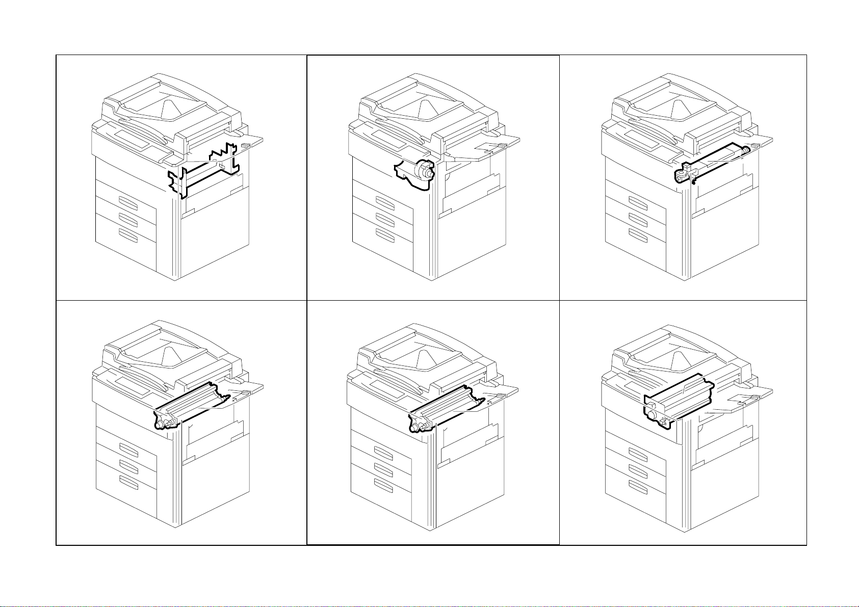
Location of Unit
1.Exterior 1 (A229)
See Page 15
4.DF Exterior (A229)
2.Exterior 2 (A229)
See Page 17
5.Original Feed 1 (A2 29)
3.Operation Panel (A229)
See Page 19
6.Original Feed 2 (A229)
See Page 21
See Page 23
3
See Page 25
Page 7
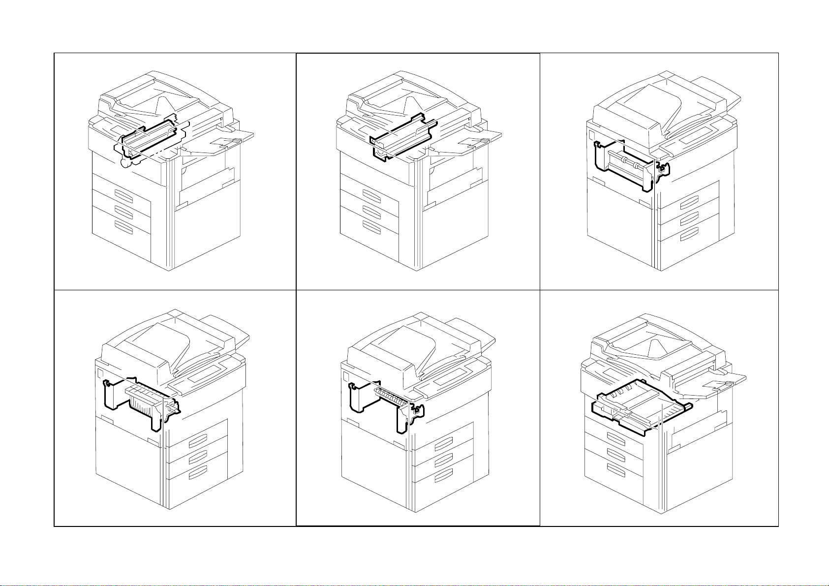
Location of Unit
7.Original Feed 3 (A229)
See Page 27
10.Original Exit 2 (A2 29)
8.Original Trans por t (A22 9)
See Page 29
11.DF Drive Section 1 (A229)
9.Original Exit 1 (A2 29)
See Page 31
12.DF Drive Section 2 (A229)
See Page 33
See Page 35
4
See Page 37
Page 8
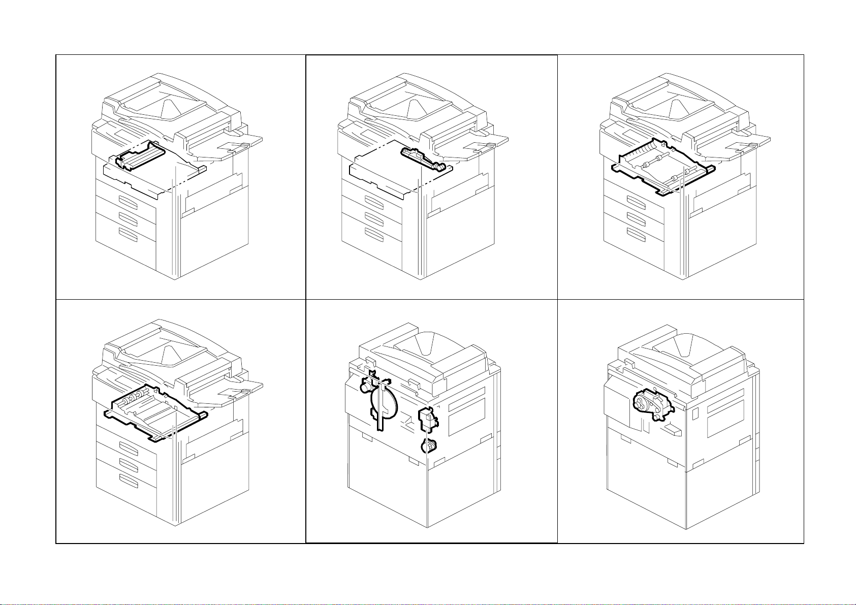
Location of Unit
13.DF Frame Section (A229)
See Page 39
16.Optics Sect ion 3 (A229)
14.Optics Section 1 ( A229)
See Page 41
17.Optics Section 4 ( A229)
15.Optics Section 2 (A2 29)
See Page 43
18.Laser Unit (A229)
See Page 45
See Page 47
5
See Page 49
Page 9
Location of Unit
19.By-pass Feed Uni t (A229)
See Page 51
22.Universal Tray ( A229)
20.Tandem Tray 1 (A229)
See Page 53
23.LCT Tray 1 (A229)
21.Tandem Tray 2 ( A 229)
See Page 55
24.LCT Tray 2 (A229 )
See Page 57
See Page 59
6
See Page 61
Page 10

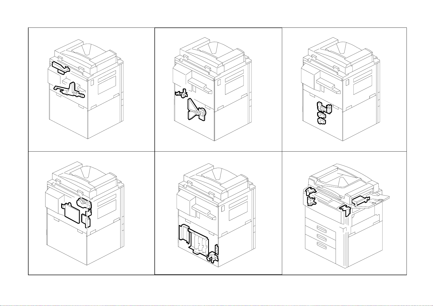
Location of Unit
25.Paper Feed Uni t 1 (A22 9)
See Page 63
28.Vertical Transport (A229)
26.Paper Feed Uni t 2 (A229)
See Page 65
29.Paper Registrat i on 1 ( A229)
27.Paper Feed Unit 3 (A2 29)
See Page 67
30.Paper Registra tio n 2 (A2 29)
See Page 69
See Page 71
7
See Page 73
Page 11
Location of Unit
31.Paper Registra tio n 3 (A229)
See Page 75
34.Development Un it 1 (A 229)
32.Toner Bottle Holder (A2 29)
See Page 77
35.Development U nit 2 (A22 9)
33.Toner Hopper Sect ion (A229)
See Page 79
36.PCU 1 (A229)
See Page 81
See Page 83
8
See Page 85
Page 12

Location of Unit
37.PCU 2 (A229)
See Page 87
40.Transfer Belt Uni t 1 (A229)
38.PCU 3 (A229)
See Page 89
41.Transfer Belt Unit 2 (A2 29)
39.PCU 4 ( A229)
See Page 91
42.Fusing Unit 1 (A229)
See Page 93
See Page 95
9
See Page 97
Page 13
Location of Unit
43.Fusing Unit 2 (A229)
See Page 99
46.Paper Exit Unit 2 (A22 9)
44.Fusing Unit 3 (A229)
See Page 101
47.Paper Exit Unit 3 (A229)
45.Paper Exit Unit 1 (A 229)
See Page 103
48.Inverter/Dup l ex Uni t 1 (A2 29)
See Page 105
See Page 107
10
See Page 109
Page 14
Location of Unit
49.Inverter/Dup l ex Uni t 2 (A2 29)
See Page 111
52.Inverter/Dup l ex Uni t 5 (A2 29)
50.Inverter/Duplex Unit 3 (A229)
See Page 113
53.Drive Section 1 (A2 29)
51.Inverter/Duplex Unit 4 (A229)
See Page 115
54.Drive Section 2 (A229)
See Page 117
See Page 119
11
See Page 121
Page 15
Location of Unit
55.Drive Section 3 (A229)
See Page 123
58.Electrical Section 1 (A229)
56.Drive Section 4 (A2 29)
See Page 125
59.Electrical Section 2 (A229)
57.Drive Section 5 (A229)
See Page 127
60.Electrical Section 3 (A229)
See Page 129
See Page 131
12
See Page 133
Page 16

Location of Unit
61.Frame Section 1 (A229)
See Page 135
64.Option Exit Tra y (A8 14)
62.Frame Section 2 ( A229)
See Page 137
65.Key Counter unit (A6 74)
63.Frame Section 3 (A2 29)
See Page 139
See Page 141
See Page 143
13
Page 17

1.Exterior 1 (A229)
14
Page 18

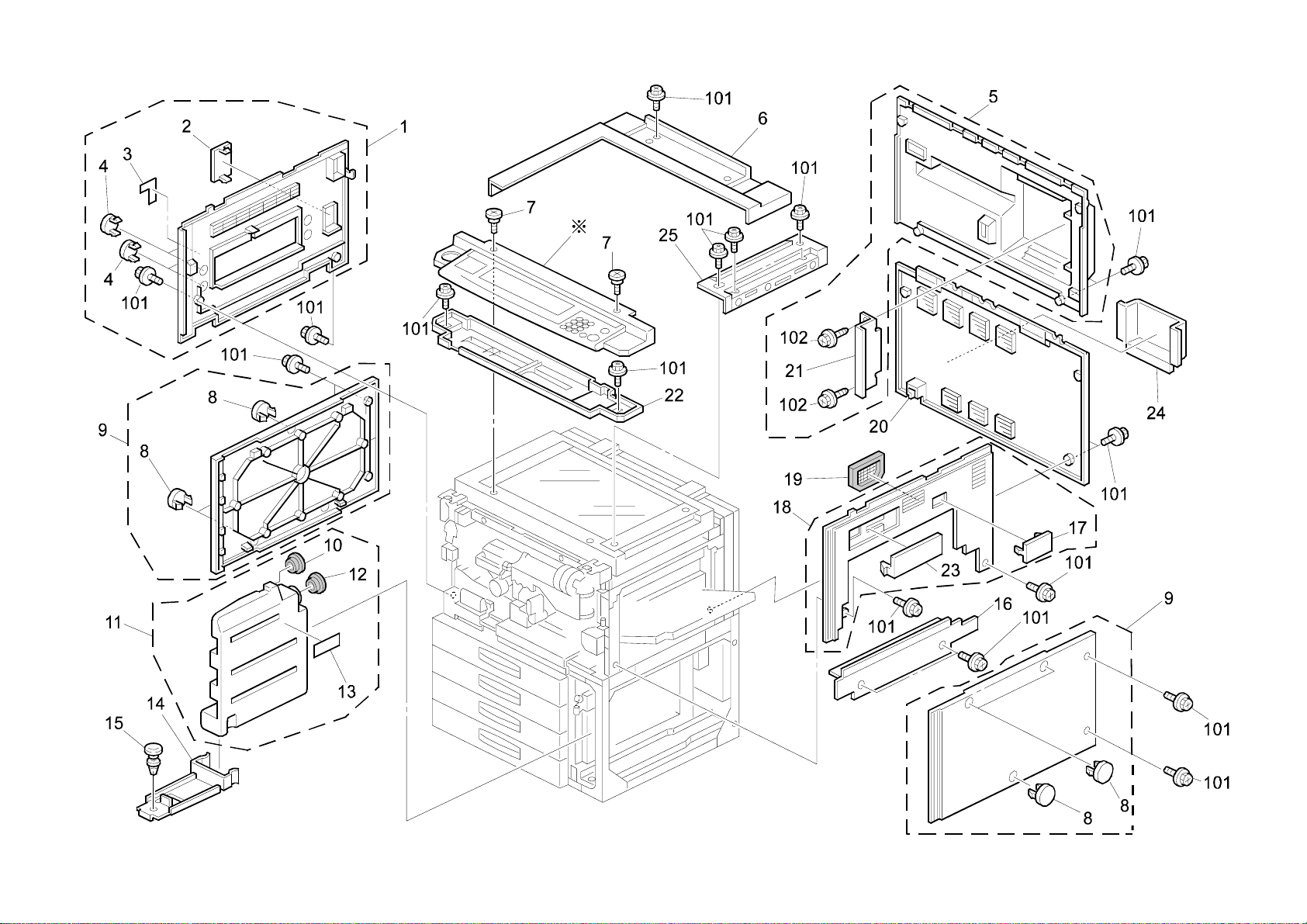
1.Exterior 1 (A229)
Index
No.
1 A229 1349 Decal - Toner Supply 1
2 A229 1350 Decal - Misfee d Rem ov al 1
3 A229 1275 Guide Plate Lev er 1
4 A229 1347 Fusing Unit Lever Feeler 1
5 A229 1342 Upper Hinge 1
6 AG07 0004 Magnetic Catch 1
7 A229 1257 Door Grip Ass’y 1
8 A229 1253 Front Door (RIC) 1
8 A229 1302 Front Door (SVN/NRG) 1
8 A229 1241 Front Door (INF) 1
9 A229 1355 Micro Switch Le ver 1
10 A229 1259 Lower Hinge 1
11 A134 1383 Emblem (RIC) 1
11 A229 7016 Support Cover (INF) 1
12 A096 6184 Bank Inner Cover 1
13 AG05 0067 Knob - Transport Roller 1
14 AA00 0540 Decal - Misfeed R em ov al 1
15 A229 3298 Pawl Cover Sheet 1
16 A229 1320 Right Lo wer Inn er Co ver 1
17 A229 7010 Model Nam e Plat e - GES 32 65 1
17 A229 7011 Model Nam e Plat e - NSA D46 5 1
17 A229 7012 Model Nam e Plat e - REX 2865 1
17 A229 7013 Model Nam e Plat e - SVN 9965D P 1
17 A229 7015 Model Nam e Plat e - 170X60 NRG 1
18 A060 2512 Registration Roller Knob 2
19 A229 3290 Right Inne r Cover 1
20 A229 1321 Safty Switch In ner Cover 1
Part No.
Description
Q’ty Per
Assembly
Index
No.
101 0450 4008B Tapping Screw - 4x8
102 0802 5124 Tapping Screw - M3x8
103 0434 0082W Tapping Screw - M4x 8
104 0951 4006B Philips Screw With Washer - M4x6
105 0451 4008B Philips Tapping Screw - M4x8
106 0951 3006B Philips Screw With Flat Washer - M3x6
107 0450 3008B Tapping Screw - M3x8
Part No.
Description
Q’ty Per
Assembly
15
Page 19
2.Exterior 2 (A229)
16
Page 20

2.Exterior 2 (A229)
Index
No.
1 A22 9 1272 Left Upper Cover (230V) 1
1 A22 9 1271 Left Upper Cover (120V) 1
2 A229 1333 Connector Cap 1
3 A22 9 1361 Decal - Main Switch (230V) 1
3 A22 9 1360 Decal - Main Switch (120V) 1
4 A247 1299 Cap - 22 2
5 A229 1273 Rear Upper Cover 1
6 A229 1310 Upper Cover 1
7 AA14 3416 Stepped Screw - M4x3 2
8 A247 1318 Cap - 17 6
9 A229 1270 Lower Cover 2
10 AA15 2315 Tank Seal 1
11 AA03 2041 Tonner Collection Bottle 1
12 A007 3751 Cap Large - Ton er Co ll ect ion Tank 1
13 AA00 0059 Caution Decal - English 1
14 A096 3711 Collection Tank Holder 1
15 A096 3712 Ratch 1
16 A229 1304 Large Cap aci t y Tray Cover 1
17 A229 1332 Couplin g C ap 1
18 A229 1260 Upper Ri ght C over 1
19 A229 1262 Optics Dust Filter 1
20 A229 1309 Rear Lower C ove r 1
21 A229 1359 Shading Plat e 1
22 A229 1327 Operati on Panel Upper Cover 1
23 A229 1331 Key Counter Cap 1
24 A229 8521 Operati ng I nst r ucti ons Holder - A5 1
25 A229 1311 Upper Ri ght C over 1
Part No.
Description
Q’ty Per
Assembly
Index
No.
101 0451 4008H Tapp i ng Scr ew - 4x8
102 0450 3008B Ta pping Screw - M3x8
Part No.
Description
Q’ty Per
Assembly
17
Page 21

3.Operation Panel (A229)
18
Page 22

3.Operation Panel (A229)
Index
No.
1 A229 1412 Operation Panel Ass’y (LT) 1
1 A229 1414 Operation Pane l Ass’y ( A 4) 1
2 A229 1442 Operation Pane l Case ( A 4) 1
2 A229 1441 Operation Pane l Case ( LT) 1
3 A229 1466 Guidance Shee t 1
4 A229 1461 Application Cap 1
5 A229 1465 LED Guide 1
6 A229 1459 Keytop - Power Source 1
7 A229 1457 Keytop - Check 1
8 A229 1456 Keytop - Interrupt 1
9 A229 1475 Key-top - Standby 1
10 A229 1455 Keytop - Program 1
11 A229 1451 Keytop - 10key 1
12 A229 1453 Keytop - Clear/St op 1
13 A229 1452 Keytop - Start 1
14 AW01 007 9 Optics Sensor 1
15 A229 1462 10key Board 1
16 A229 1468 10key Sheet 1
17 A229 1433 LCDC Cover 1
18 A229 5200 LCDC Board 1
19 A229 1432 LCDC Bracket 1
20 A229 5215 HVGA LCD 1
21 A229 1425 Touch Panel Ass’y 1
22 A229 1463 Application Board 1
23 A229 1467 Application Sheet 1
24 A229 1458 Keytop - Tool 1
25 A229 1460 Dial - Contrast 1
26 A153 6409 Decal - Keytop Cover (GES/NRG) 1
26 C225 2866 Decal - Keytop Cover (R EX) 1
26 C225 2867 Decal - Keytop Cover (NASHUA) 1
Part No.
Description
Q’ty Per
Assembly
Index
No.
101 0451 3006B Tapping Screw - M3x6
Part No.
Description
Q’ty Per
Assembly
19
Page 23
4.DF Exterior (A229)
20
Page 24

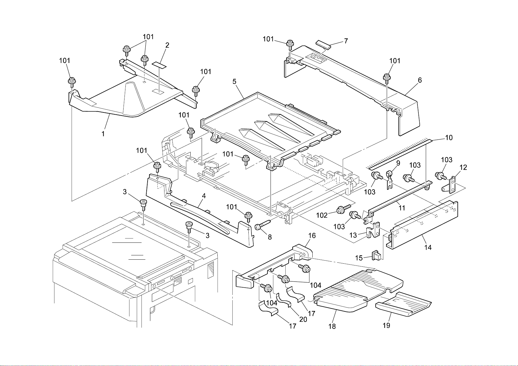
4.DF Exterior (A229)
Index
No.
1 A806 1821 Original Table 1
2 A610 6051 Decal - Document Set 1
3 A376 4911 Stepped Screw - Left Hinge 2
4 A806 1711 Front Cover 1
5 A806 1791 Original Table Cover 1
6 A806 1731 Rear Cover 1
7 A806 4341 Display Panel 1
8 5446 2824 Screw - Duplex Guide Plate 1
9 A548 1241 Driven Roller Ass’y 4
10 AA12 0032 Antistatic Brush 1
11 A806 3266 Discharge Brush Bracket 1
12 A806 3261 Inner Back Cove r Bracket 1
13 A806 3251 Exit Cove r Brack et 1
14 A806 1781 Exit Cover 1
15 G012 1531 Magnet 2
16 A229 1393 Exit Tray Holder 1
17 A229 1395 Mylar - Large 2
18 A229 1394 Exit Tray 1
19 A666 2421 Sub - Shift Tray 1
20 A229 1396 Mylar - Small 1
Part No.
Description
Q’ty Per
Assembly
Index
No.
101 0451 3008B Tapping Screw - M3x8
102 0951 5010B Philips Screw With Washer - M5x10
103 0450 4012B Tapping Screw - M4x12
104 0451 4008H Tapping Screw - 4x8
Part No.
Description
Q’ty Per
Assembly
21
Page 25

5.Original Feed 1 (A229)
22
Page 26

5.Original Feed 1 (A229)
Index
No.
1 A806 1751 Feed Cover 1
2 A806 4311 Decal - Misfee d Rem oval 1
3 A806 1371 Magnet Catch - Paper Feed Cover 2
4 A806 4331 Decal - Original Size 1
5 A806 1361 Cover Bracket 1
6 A806 1181 Pressure Roller Bracket - Pull Out 2
7 A806 4222 Compression Spring 2
8 A680 1661 Bushing - 4mm 4
9 A806 1196 Driven Roller 1
10 A806 5710 Pull Out Sensor Ha rness 1
11 5446 282 4 Screw - Dupl ex Gu i de Plat e 1
12 A806 4211 Compression Spring 2
13 A806 1191 Pull Out Driven Roller 1
14 A806 1335 Original Table Guide Plate 1
15 AW01 007 6 Photosensor - PS-117D1 1
16 A806 1171 Turn Guide Plate 1
17 A806 1881 Side Fence 1
18 A376 4599 Side Fence Pad 1
19 A806 1351 Original Sensor Feeler 1
20 A806 1353 Feeler Stud 1
21 A680 4151 Side Fence Guide 1
22 5206 268 6 Sna p R ing 1
23 A806 1861 Original Table Base 1
24 5215 262 1 Sna p R ing - M6 1
25 A806 4321 Decal - Or igi na l Stack H ight 1
26 A806 5730 Original Sensor Harness 1
27 AW02 0075 Photointerrupter 2
28 A806 1356 Original Sensor Bracket 1
29 A806 2281 Gear - Z47 1
30 5053 0447 Bushing - 6mm 1
31 A806 1346 Base Shaft 1
32 A806 1342 Base Lever 1
33 5053 0223 Bushing - 8mm 1
34 A806 1331 Original Table Stay 1
35 A806 5785 Grounding Harness 1
Part No.
Description
Q’ty Per
Assembly
Index
No.
36 A806 5780 Grounding Harness 1
101 0450 4008B Tapping Screw - 4x8
102 0451 3008B Tapping Screw - M3x8
103 0720 0030B Retaining Ring - M3
104 0450 3008B Tapping Screw - M3x8
105 1105 0199 Clamp
106 1105 0328 Harness Clamp - ES-0505
107 0632 0140G Paral lel Pin
108 0720 0040B Retaining Ring - M4
109 0720 0060B Retaining Ring - M6
Part No.
Description
Q’ty Per
Assembly
23
Page 27

6.Original Feed 2 (A229)
24
Page 28

6.Original Feed 2 (A229)
Index
No.
1 A806 1152 Upper Guide Plate 1
2 A806 1151 Upper Guide Plate 1
3 A806 1286 Bushing 1
4 A806 1161 Entrance Guide Plate - Front 1
5 A806 1163 Guide Plate Cush i on 4
6 A680 1621 Feed-in Unit Stoppe r 1
7 A628 1225 Bushing - 8mm 4
8 A806 1296 Transport Belt Roller 1
9 A806 1291 Transport Belt Bracket 1
10 A680 1241 Feed Belt 1
11 A806 1297 Transport Belt Roller 1
12 A806 1298 Transport Belt Roller Shaft 1
13 AA06 3318 Spring - Belt Guide Rolle r 2
14 A806 1282 Separation D ri ve Sha ft 1
15 A806 1162 Entrance Guide Plate - Inner 1
16 A806 1327 Release Lever 1
17 A806 1312 Pickup Roller Bracket 1
18 A806 2271 Gear - Z18 1
19 A806 2151 Timing Pull ey - T19 /Z 23 S2M / M0. 6 1
20 5447 268 1 Sna p R ing 3
21 5053 0447 Bushing - 6mm 2
22 A806 4118 Timing Belt - B40S2M148 1
23 A806 1321 Pickup Roller 1
24 AA13 2171 Spacer - 6x20x1 1
25 A806 2153 Timing Pulley - T27 S2M 1
26 A680 1671 Separatio n Ro lle r 1
27 A247 2900 Torque Lim i ter - 53 m nxm 1
28 A806 1141 Reverse Roller Stay 1
29 A806 5725 Sensor Harness 1
30 5415 4145 Stud 1
31 AA06 3315 Spring - Belt Drive Shaft 1
32 A806 2512 Reverse Roller Shaft 1
33 A418 1158 Spacer - M6.5x 1 2
Part No.
Description
Q’ty Per
Assembly
Index
No.
101 0451 3008B Tapping Screw - M3x8
102 0720 0040B Retaining Ring - M4
103 0720 0060B Retaining Ring - M6
104 1105 0199 Clamp
105 1105 0231 Clamp
106 0741 3506 Ball Bearing - 6x12x4 mm
107 0622 0120E Spring Pin - 2x12mm
108 0741 3706 Ball Bearing - 6x10x3
Part No.
Description
Q’ty Per
Assembly
25
Page 29

7.Original Feed 3 (A229)
26
Page 30

7.Original Feed 3 (A229)
Index
No.
1 AA14 3074 Stepped Screw - M4x5 1
2 A806 1271 Pull Out Drive Roller 1
3 A806 1276 Transport Driv e R oll er 1
4 A806 5745 Paper Siz Sensor Harness 1
5 AW02 0104 Photointerruptor 1
6 AW02 0095 Photointerruptor 2
7 A806 1226 Paper Size Sensor Bracket 1
8 A806 1211 Middle Guide Plate 1
9 A806 1241 Lower Guide Plate 1
10 A806 1251 Transpo rt Rol ler Arm 4
11 A806 4222 Compression Spring 2
12 A806 1266 Driven Roller 2
13 5324 165 8 Bus hi ng - 4x 8x4.5mm 2
14 A806 4221 Compression Spring 2
15 A806 1261 Middl e Driven Roller 1
16 A806 1256 Middle Shaf t - Roller Arm 1
17 A806 1257 Roller Arm Shaft 2
18 A806 1231 Paper Feed Base 1
19 A376 3242 Antistatic Brush 1
20 A422 1063 Seal - 0.7x13x20 1
21 AW02 0075 Photointerrupter 1
22 A806 1221 Registration Sensor Bracket 1
23 AW01 007 6 Photosensor - PS-117D1 1
24 A806 5740 Registration Sensor Harness 1
25 A806 5735 Pick Up Sensor Harness 1
Part No.
Description
Q’ty Per
Assembly
Index
No.
101 0741 3506 Ball Bearing - 6x12x4 mm
102 0720 0040B Retaining Ring - M4
103 0451 3008B Tapping Screw - M3x8
104 1105 0328 Harness Clamp - ES-0505
105 0451 3006B Tapping Screw - M3x6
106 1105 0199 Clamp
107 0720 0030B Retaining Ring - M3
108 0450 3008B Tapping Screw - M3x8
109 1106 0193 Bushing - 7.9mm
110 0451 3012B Tapping Screw With Washer - M3x12
111 0741 3808 Ball Bearing - 8x16x5mm
Part No.
Description
Q’ty Per
Assembly
27
Page 31

8.Original Transport (A229)
28
Page 32

8.Original Transport (A229)
Index
No.
1 A663 1412 Transport Base Plate 1
2 5419 5714 Stepped Screw - M4 8
3 A232 3563 Ball Bearing - 6x12x 4 3
4 A680 1481 Transport Belt 1
5 A680 1431 Belt Drive Roller 1
6 A680 1451 Belt Pressure Roller 1
7 A548 1461 Belt Pressure Roller 3
8 A548 1442 Transport Arm 1
9 A610 2161 Belt Pressure Roller - 24 1
10 A663 1422 Transpo rt Stay 1
11 A376 2132 Belt Driven Roll e r 1
12 A680 1446 Transport Unit Arm 1
13 A680 1443 Arm Shaft 1
14 A806 4114 Timing Belt - B40S3M174 1
15 A548 2139 Pulley 1
16 5053 0447 Bushing - 6mm 2
Part No.
Description
Q’ty Per
Assembly
Index
No.
101 0720 0040E Retaining Ring - M4
102 0805 0089 Retaining Ring - M4
103 0720 0030E Retaining Ring - M3
104 0451 3006B Tapping Screw - M3x6
105 0720 0040B Retaining Ring - M4
Part No.
Description
Q’ty Per
Assembly
29
Page 33

9.Original Exit 1 (A229)
30
Page 34

9.Original Exit 1 (A229)
Index
No.
1 A806 3162 Reverse Exit Guide 1
2 AW01 0076 Photosensor - PS-117D1 2
3 A806 3161 Left Guide Plate 1
4 A806 3151 Driven Exit Roller 4
5 A806 3142 Guide Plate Bracket 1
6 A806 4233 Tension Spring 4
7 A806 3171 Lower Exit Cover 1
8 A806 3291 Original Stopper Cushion 4
9 A548 1233 Driven Roller 4
10 A548 1234 Driven Roller Arm 4
11 A806 3131 Lower Exit Guid e Pl at e 1
12 5053 0447 Bushing - 6mm 2
13 A806 3281 Timing Pulley - T14 S3M 1
14 A806 4122 Timing Belt - B40S3M150 1
15 A806 3211 Right Exit Guide Plate 1
16 AA12 0032 Antistatic Brush 1
17 A806 3222 Seal 1
18 A806 3221 Exit Ground Plate 1
19 AW02 0075 Photointerrupter 1
20 A806 1921 Right Cover 1
21 A806 3111 Drive Exit Roller 1
Part No.
Description
Q’ty Per
Assembly
Index
No.
101 0720 0040B Retaining Ring - M4
102 0451 3008B Tapping Screw - M3x8
103 0450 3008B Tapping Screw - M3x8
Part No.
Description
Q’ty Per
Assembly
31
Page 35

10.Original Exit 2 (A229)
32
Page 36

10.Original Exit 2 (A229)
Index
No.
1 A680 2321 Pulley - 30T 2
2 5053 0447 Bushing - 6mm 5
3 A548 1217 Antistatic Brush - Paper Exit 1
4 AA06 0588 Pressure Spring 4
5 A548 1233 Driven Roller 4
6 A548 1234 Driven Roller Arm 4
7 A806 3181 Reverse Guide Plate 1
8 A548 1261 Exit Roller 1
9 A548 1320 Inverter Gate Plat e 1
10 A548 1317 Lever Cushion 2
11 A806 4232 Tension Spring 1
12 A806 3271 Reverse Drive Roller 1
13 A548 1231 Guide R oll er 1
14 5215 262 1 Sna p R ing - M6 1
15 A806 3191 Exit Junct ion G at e 1
16 A806 4231 Tension Spring 1
17 A806 4121 Timing Belt - B40S3M213 1
18 A548 2137 Timing Pulley - 18Z 1
19 A469 3113 Rubber Seal - 1x6x 10m m 2
20 A806 3311 Invertor Sol enoid 1
21 A680 1384 Solenoid - Lower Inverter Gate 1
22 A806 3312 Solenoid Bracket 1
Part No.
Description
Q’ty Per
Assembly
Index
No.
101 0720 0040B Retaining Ring - M4
102 0632 0120G Parallel Pin - 2x12
103 0805 0089 Retaining Ring - M4
104 0451 3008B Tapping Screw - M3x8
105 1105 0328 Harness Clamp - ES-0505
106 0353 0030B Philips Truss Head Screw - M3x3
Part No.
Description
Q’ty Per
Assembly
33
Page 37

11.DF Drive Section 1 (A229)
34
Page 38

11.DF Drive Section 1 (A229)
Index
No.
1 A806 4116 Timing Belt - B40S3M177 1
2 A806 2141 Timing Pulley - T22 S3M 1
3 5053 0447 Bushing - 6mm 2
4 A806 2122 Timing Pulley - T24 1
5 A806 4113 Timing Belt - B40S3M276 1
6 A806 2113 Timing Pulley - T23 S3M 1
7 5937 4158 Spring Washer - BD10 2
8 A806 2322 Paper Feed Stay 1
9 A806 4234 Tension Spring 1
10 AB03 0354 Pulley - 20T 1
11 A806 2921 Stepper Motor Ass’y - DC30.4W 1
12 A680 2611 Stepping Mot or - DC 6.7W 1
13 A806 5720 Paper Feed Motor Harness 1
14 A806 2311 Motor Bra cke t 1
15 A806 2711 Display Bracket 1
16 5936 523 1 Indi c at or Boar d 1
17 A806 4112 Timing Belt - B40S2M408 1
18 A806 4111 Timing Belt - B60S2M200 1
19 A680 2231 Pulley - 44T/20T 1
20 A806 2111 Timing Pulley - T28 S2M 1
21 5936 232 1 Rubber Bushing - Vibratio n Dam per 3
22 A806 2232 Gear - 18Z 1
23 A806 2611 Gear Stopper 1
24 A806 2233 Gear Shaft - 18Z 1
25 A806 2213 Gear - 22Z 1
26 A806 2331 Paper Feed Bracket 1
27 A680 2262 Feeler - Pick -up R oll er Cam 1
28 A806 2211 Gear - 22Z 1
29 A806 2422 Pick-up Roller Cam 1
30 AW02 0075 Photointerrupter 1
31 A806 2351 Pickup Roll e r M otor Bra cket 1
32 A806 2131 Timing Pull ey - T37 /T 18 S2M / S3M 1
33 A806 4115 Timing Belt - B40S2M116 1
34 AX04 0096 Stepping Motor - DC 18W 1
35 A806 5750 Sensor Harness 1
Part No.
Description
Q’ty Per
Assembly
Index
No.
101 0720 0040B Retaining Ring - M4
102 0632 0120G Parallel Pin - 2x12
103 0741 3506 Ball Bearing - 6x12x4 mm
104 0701 0030B Flat Washer - M3
105 0451 3008B Tapping Screw - M3x8
106 0353 0050B Philips Truss Head Screw - M3x5
107 0354 0060B Screw - M4X6
108 1105 0199 Clamp
109 1105 0231 Clamp
Part No.
Description
Q’ty Per
Assembly
35
Page 39

12.DF Drive Section 2 (A229)
36
Page 40

12.DF Drive Section 2 (A229)
Index
No.
1 A806 2283 Gear - Z20/Z47 2
2 A806 2161 Timing Pulley - T30 /Z20 S2M / M 0. 8 1
3 AA13 2152 Spacer - 8x20x1 1
4 A806 2362 Base Bracket 1
5 A806 3291 Original Stopper Cushion 1
6 A806 2911 Stepper Motor Ass’y 1
7 A806 5750 Sensor Harness 1
8 A806 5755 On Off Detector Harness 1
9 A806 5765 Exit Sensor Harness 1
10 A806 5510 ADF Main Control Board 1
11 A806 5760 Reverse Sensor Harness 1
12 A806 4117 Timing Belt - B40S2M158 1
13 A806 5705 Display Harness 1
14 A806 5715 Pick Up Motor Harness 1
15 A806 5770 DF Harness 1
16 A806 3241 Exit Motor Brac ket 1
17 A806 4252 Grounding Plate 1
18 A680 2311 Pulley - 18T/32T 1
19 AA04 3380 Timing Belt - B40S2M116 1
20 A300 3812 Spacer - 6x22x1.5 1
21 5936 232 1 Rubber Bushing - Vibratio n Dam per 1
22 A806 2287 Gear - Z20/Z4 7 1
23 A806 2285 Gear - Z20/Z4 7 1
24 A806 2225 Gear - 36Z 1
25 A806 2223 Gear - 36Z 1
26 A806 2221 Gear - 27Z 1
27 AW02 0075 Photointerrupter 1
28 A806 2243 Separation D r ive Shaft 1
29 A806 2261 Gear - Z30 2
30 A806 2253 Gear - Z31 1
31 A806 2242 Gear - 27Z 1
32 A806 2251 Gear - Z19 1
33 A806 2244 Separation Shaft Stopper 1
34 A663 2621 Exit Motor - 3.7V 14. 8W 1
35 A680 1171 Harness Holder 1
Part No.
Description
Q’ty Per
Assembly
Index
No.
36 A806 5773 Sadf Harness 1
101 0451 3008B Tapping Screw - M3x8
102 0353 0050B Philips Truss Head Screw - M3x5
103 1105 0199 Clamp
104 0720 0060B Retaining Ring - M6
105 0720 0040B Retaining Ring - M4
106 0741 3506 Ball Bearing - 6x12x4 mm
107 0632 0160G Paral lel Pin-m2x16
108 0451 4008B Philips Tapping Screw - M4x8
109 1 107 0750 Fuse - 3.15A 250V
Part No.
Description
Q’ty Per
Assembly
37
Page 41

13.DF Frame Section (A229)
38
Page 42

13.DF Frame Section (A229)
Index
No.
1 A548 1541 Safety Switch Bracket 1
2 A680 1181 Magnetic Catch 2
3 A806 1131 Left Frame Stay 1
4 A806 1135 Contact Point Shaft 2
5 A548 1135 Spring Plate 2
6 AA14 3039 Spring Holder 2
7 AW02 0075 Photointerrupter 2
8 A351 4281 Anti-vibration Cushion 2
9 A806 1511 Left Hinge 1
10 A806 1133 Right Frame Stay 1
11 A806 1521 Right Hinge 1
12 A548 1531 Safety Switch Fe eler 1
Part No.
Description
Q’ty Per
Assembly
Index
No.
101 0451 3008B Tapping Screw - M3x8
102 0720 0030B Retaining Ring - M3
103 1105 0334 Edge - 17
104 0314 0060B Philips Pan Head Screw - M4x6
105 0951 4006B Philips Screw With Washer - M4x6
106 1105 0199 Clamp
Part No.
Description
Q’ty Per
Assembly
39
Page 43

14.Optics Section 1 (A229)
19
40
Page 44

14.Optics Section 1 (A229)
Index
No.
1 A229 1825 Home Position Sensor Bracket 1
2 AW02 0056 Photointerruptor - EE-SX4235A-P1 1
3 5206 2684 Shoulde r Screw - M3 5
4 A229 1778 Left Scale 1
5 A193 1752 Left Scale Guide 1
6 A229 1775 Scale Left Bracket 1
7 AC01 2065 Exposure Glass - A3 T-3.2 1
8 AA15 0636 Seal - 90x29.5x0.2 1
9 AA16 1138 Cushion - 1.1 4
10 A229 1831 Fan Bracket 1
11 A229 1781 Rear Scale 1
12 A229 1819 BICU Inner Cover 1
13 A229 1822 Right Inne r Cover 1
14 A229 1785 Right Stay 1
15 AX64 0083 Cooling Fan 1
16 A229 1824 Inner Cover Angle 2
17 AA15 0332 Seal - 0.19x18x22 1
18 AA16 1137 Cushion - 0.5 2
19 AA16 1139 Cushion - Xenon Lamp 2
Part No.
Description
Q’ty Per
Assembly
Index
No.
101 0451 3006B Tapping Screw - M3x6
102 0314 0300B Philip s Pan Head Screw - M4x30
Part No.
Description
Q’ty Per
Assembly
41
Page 45

15.Optics Section 2 (A229)
42
Page 46

15.Optics Section 2 (A229)
Index
No.
1 A229 9061 LD Unit 1
2 AW01 0034 Original Width Sensor 1
3 A229 1695 Laser Diode Unit Cover 1
4 A229 1691 Polygon Mirror Motor Cover 1
5 AX06 0149 Polygon Mirror Mot or Ass’y 1
6 A229 1796 Lens Unit 1
7 A229 5466 Scanner Harness 1
8 AW01 0078 Photosensor H=50 2
9 A229 1763 Original Sensor Bracket 1
10 A229 5405 LCDC Harness 1
11 A229 9099 NVRAM - Minus Counter 1
12 A229 7603 APS23 Scanner Harness 1
13 A229 7530 SBICU Board - 120V 1
13 A229 7550 SBICU Board - 230V 1
14 A229 1823 Inner Cover Bracket 1
15 A229 5472 MSU Harness 1
16 A229 1816 Key Counter Bracket 1
17 A096 5464 Key Counter Connector 1
18 A229 5426 Laser Diode Control Harness 1
19 A229 5430 Inner Harness 1
20 A229 5429 Power Harness 1
21 A229 5468 APS1 Hp Harness 1
22 A229 5507 Main Contro Harness 1
23 A229 5467 Motor Driver Harness 1
24 A229 5400 SBICU Harness 1
25 A229 5427 Stepper Motor Harness 1
26 A229 5150 12VA Board 1
Part No.
Description
Q’ty Per
Assembly
Index
No.
101 0353 0080B Screw - M3X8
102 0451 3012B Tapping Screw With Washer - M3x12
103 0353 0060B Philips Pan Head Screw - M3x6
104 0354 0060B Screw - M4X6
105 1105 0291 Metal Cable Clamp
106 1105 0306 Metal Clamp - Al-4
107 1102 6247 Connector - 4P
108 0451 4010B Tapping Screw - 4x10
Part No.
Description
Q’ty Per
Assembly
43
Page 47

16.Optics Section 3 (A229)
44
Page 48

16.Optics Section 3 (A229)
Index
No.
1 AC03 0074 2nd Mirror 2
2 A134 1791 Spring Plate - 2nd Mirror 4
3 AX50 0063 Xenon Lamp 1
4 A229 1736 Front Bracket 1
5 A134 1726 Wire Stopper Plate 2
6 AX40 0063 Anticondensation Heater - 12 0V 9W 1
6 AX40 0064 Anti Condensation Heater - 230V 9W 1
7 A229 5463 Xenon Lamp Flexi ble Board 1
8 AZ50 0052 Lamp Stabilizer 2
9 A229 1811 Invertor Bracke t 1
10 AB03 2717 Pulley - 26Z 4
11 A069 1883 Shoe - Scanne r 8
12 A229 1740 1st Mirror Ass’y 1
13 AA13 2174 Spacer - M8 2
14 A134 1776 Spring Plate - 1st Mirror 2
15 A229 1732 Carriage Frame 1
16 A096 1873 Scanner Sho e Pin 8
17 A229 1738 Rear Bracket 1
18 A134 1782 2nd Scanner Ass’ y 1
Part No.
Description
Q’ty Per
Assembly
Index
No.
101 0353 0080B Screw - M3X8
102 0951 3006B Philips Screw With Flat Washer - M3x6
103 0450 3006B Tapping Screw - M3x6
104 1105 0194 PCB Stud
105 1105 0229 Clamp
106 0353 0060B Philips Pan Head Screw - M3x6
107 0720 0060E Retaining Ring - M6
Part No.
Description
Q’ty Per
Assembly
45
Page 49

17.Optics Section 4 (A229)
46
Page 50

17.Optics Section 4 (A229)
Index
No.
1 AA16 1104 Cushion - Motor 4
2 A134 1698 Idle Pulley 2
3 A229 1715 Drive Shaft 1
4 AA06 0221 Gripper Solenoid Spring 2
5 A229 1720 Front Tension Bracket 1
6 AB03 2718 Drive Pulley 2
7 A229 1719 Carrige Drive Wire 2
8 AB03 2717 Pulley - 26Z 2
9 A229 1823 Inner Cover Bracket 1
10 G020 1917 Decal - LD 1
11 5353 328 3 Insert Cap 1
12 G020 1920 Decal - Laser Diode (115V) 1
12 G020 1918 Decal - Laser Diode (230V) 1
13 A229 1808 Flexible Board Guide 1
14 A229 1806 Lower Insulating Sheet 1
15 A229 1721 Tension Wire Bracket 1
16 A229 5331 Motor Control Board 1
17 AA06 0763 Tension Spring 1
18 A229 1710 Scanner Stepped Motor Ass’y 1
19 AA04 3900 Timing Belt - S2M 274M M 1
20 AB03 0595 Timing Pulley - 66 1
21 A134 1722 Bracket - Drive Shaft 1
22 A229 1805 Upper Insulating Sheet 1
23 A229 1835 Motor Control Board Bracket 1
24 A229 1694 Shielding Sheet 1
25 A229 1687 Lens Block Holder 2
26 A229 1815 Key Counter Bracket - Front 1
27 A229 1686 Rear Frame Shield 1
Part No.
Description
Q’ty Per
Assembly
Index
No.
101 0707 4050B Bushing - 4 X5
102 0354 0060B Screw - M4X6
103 0951 4010B Philips Screw With Washer - M4x10
104 0805 3368 Ball Bearing - 8x16x5mm
105 0575 0050E Hexagon Headless Set Screw - M5x5
106 0720 0060B Retaining Ring - M6
107 1105 0283 Clamp
108 1105 0267 Harness Clamp - YMC-10- 0
109 0353 0060B Philips Pan Head Screw - M3x6
110 0951 4006B Philips Screw With Washer - M4x6
111 1105 0230 Clamp
112 0313 0060B Philips Pan Head Screw - M3x6
113 1105 0229 Clamp
Part No.
Description
Q’ty Per
Assembly
47
Page 51

18.Laser Unit (A229)
48
Page 52

18.Laser Unit (A229)
Index
No.
1 A229 1960 Shield 1 1
2 A229 1961 Shield 2 1
3 A229 1962 Seal - 6x364 1
4 A229 1963 Shield 4 1
5 G020 1906 Left Holder - F Theta Mirror 1
6 A229 1903 Mirror Plate - No.1 2
7 G020 1907 Right Holder - F Theta Mirror 1
8 G020 1968 F Theta Mirror 1
9 AC03 0111 1st Mirror 1
10 A229 1905 Mirror Plate - No.2 2
11 G020 1928 2nd Mirror - Laser U ni t 1
12 A229 1907 Mirror Plate - No.3 1
13 AC03 0113 3rd Mirror 1
14 A217 2103 Cylindrical Lens Plate 1
15 A229 1916 Cylindrical Lens 1
16 A229 5432 Outer Harness 1
17 A229 1958 Harness Guide 1
18 A229 1924 Shield Glass Shield 1
19 AC01 5026 Shield Glass 1
20 A229 5310 Sync Detector Board 1
21 A229 1919 Sync Detector Board Plate 1
22 G020 1904 Left Holder - BTL Len s 1
23 G020 1903 Right Holder - BTL Le ns 1
24 A229 1925 BTL Lens Ass’y 1
25 A229 1923 Lower Cover 1
26 A229 1072 Upper Middle Stay 1
27 A229 1093 ADF Holder 2
28 A229 1900 Optical Housing 1
Part No.
Description
Q’ty Per
Assembly
Index
No.
101 0451 3006B Tapping Screw - M3x6
102 0451 4010B Tapping Screw - 4x10
103 0451 4008B Philip s Tapping Screw - M4x8
Part No.
Description
Q’ty Per
Assembly
49
Page 53

19.By-pass Feed Unit (A229)
50
Page 54

19.By-pass Feed Unit (A229)
Index
No.
1 A096 2707 Upper Guide - By-pass 1
2 AA02 1025 Magnet Catch 1
3 AW50 0012 Push Switch 1
4 A096 2706 By-pass Feed Cover 1
5 A053 2770 Holder - Manual Feed Table 1
6 A229 2760 By-pass Feed Ta ble Shaft 1
7 A176 2761 Front Sub Guide 1
8 A176 2741 Front Side Fence 1
9 A069 2645 Seal - 0.2x16x47 2
10 A176 2771 Rear Sub Guide 1
11 A176 2751 Rear Side Fence 1
12 A229 2711 By-pass Feed Table 1
13 A096 2780 Feed Guide Gear 2
14 A096 2782 Size Switch Bracket 1
15 A096 5335 Paper Size Switch 1
16 AB01 3492 Gear - 16Z 1
17 A053 2773 Holder - Manual Feed Table 1
18 A229 2721 By-pass Feed cover 1
19 A229 2701 By-pass Feed Table Guide 1
20 A229 2708 By-pass Feed Tabl e Ass ’ y 1
21 A229 2745 By-pass Feed Table Stay 1
22 A096 2781 By-pass Table Bracket 1
Part No.
Description
Q’ty Per
Assembly
Index
No.
101 0314 0060B Philips Pan Head Screw - M4x6
102 0434 0060B Pan Head Self-tapping Screw - M4x6
103 0452 3008Z Bind Tapping Screw - M3x8
104 0313 0060B Philips Pan Head Screw - M3x6
105 0450 3008B Tapping Screw - M3x8
106 0573 0040E Hexagon Headle ss Set Scr ew - M 3x 4
Part No.
Description
Q’ty Per
Assembly
51
Page 55

20.Tandem Tray 1 (A229)
52
Page 56

20.Tandem Tray 1 (A229)
Index
No.
1 A229 6620 Tandem Tray Fr ont Cover 1
2 AA00 2237 Decal - Paper Tray No1 1
3 A096 6630 Left Tandem Tray Ass’y 1
4 AA00 0136 Decal - Left Tandem Tray 1
5 AF01 6062 Left Front Side Fence 1
6 A096 6641 Grounding Plate 1 1
7 A096 6634 Left Rod Holder 1
8 AA14 0499 Guide Rod 2
9 A096 6632 Tandem Tray Slider 1
10 A096 6633 Right Rod Holder 1
11 A096 6629 Middle Bottom Plate 1
12 AF01 7011 Left End Fence 1
13 A096 6644 Left Rear Side Fence 1
14 AA00 2010 Decal - Paper Level 1
15 AA04 3345 Timing Belt - B30S3M888 1
16 AB03 0417 Timing Pulley - 32Z 1
17 AB03 0418 Timing Pulley - 12Z 3
18 AW02 005 6 Photointerruptor - EE-SX4235A-P1 2
19 A096 6678 Decal - Left Paper Set 1
20 AW02 0008 Photointerruptor 1
21 A096 6636 Tightener Bracket 1
22 AA06 0534 Tray Lock Spring - 19mm 1
23 A096 5418 Left Tandem Tray Harness 1
24 A096 5300 Tandem Tray Motor - DC 11W 1
25 A096 6607 Rear Bottom Plate 1
26 A096 6642 Grounding Plate 2 1
27 A096 6640 Front Bottom Plate 1
28 A096 6649 Grounding Spring Plate 1
29 A097 6550 Tightener 1
30 AA06 6559 Tension Spring 1
Part No.
Description
Q’ty Per
Assembly
Index
No.
101 0452 4010B Tapping Bind Screw - M4x10
102 0452 4008B Tapping Screw - M4x8
103 0720 0040B Retaining Ring - M4
104 0344 0050F Philips Truss Head Screw - M4x5
105 0965 3012W Tapping Screw Wit h Fl a t W asher - M3
106 1102 6245 Relay Connector - 2P
Part No.
Description
Q’ty Per
Assembly
53
Page 57

21.Tandem Tray 2 (A229)
54
Page 58

21.Tandem Tray 2 (A229)
Index
No.
1 A096 6646 Front End Fence Guide 1
2 A096 6671 Paper Guide Plate 2
3 A096 6662 Right Front End Fence 1
4 A048 2838 Nylon Rivet 4
5 A096 6676 Side Fence Support Plate 2
6 A096 6645 Right Front Side Fence 1
7 A096 5301 Stepping Motor - DC 17W 1
8 A096 6659 Front End Fence Gear 1
9 A096 6672 Motor Cover 1
10 A176 6696 End Fence Gear 1
11 A096 6673 Bottom Plate 1
12 AF01 3002 Bottom Plate Pad 1
13 AW02 005 6 Photointerruptor - EE-SX4235A-P1 2
14 A096 6653 Lift Shaft Bracket 1
15 A096 6652 Lift Shaft 1
16 A096 6695 Lift Lever 1
17 A096 6656 Paper Volume Feeler 1
18 A175 5419 Right Tandem Tray Harness 1
19 A096 6647 Rear End Fence Guide 1
20 A096 6666 Right Rear End Fence 1
21 AA13 2169 Spacer - 5.7x16x1.5 1
22 AA06 6219 Tray Lock Spring 1
23 A096 6668 Release Pawl 1
24 A176 6648 Right Rear Side Fence 1
25 AA00 2010 Decal - Paper Level 1
26 A096 6697 LCT Stopper 1
27 A096 6679 Right Tandem Tray 1
28 AA16 2062 Paper Tray Cushion 1
29 AA16 2072 Cusion 1
30 AA15 0409 End Fence Shield 1
31 A096 6677 Decal - Right Paper Set 1
32 AA00 2229 Decal - Right Tandem Tra y 1
33 A096 6694 Paper Guide Seal 1
34 A176 6695 Misfeed Removal Guide 1
35 A176 6650 Right Ass’y 1
Part No.
Description
Q’ty Per
Assembly
Index
No.
36 AA15 0411 Base Plate Shield 2
101 0951 3006B Philips Screw With Flat Washer - M3x6
102 0452 4008B Tapping Screw - M4x8
103 0805 0083 Retaining Ring - M4
104 0720 0060B Retaining Ring - M6
105 0805 3389 Bushing - 8x10x6mm
106 0314 0080B Philips Pan Head Screw - M4x8
107 0965 3012W Tapping Screw Wit h Fl a t W asher - M3
108 0344 0050F Philips Truss Head Screw - M4x5
109 0950 4008Z Philips Truss Screw - M4x8
110 0951 4006B Philip s Screw With Washer - M4x6
Part No.
Description
Q’ty Per
Assembly
55
Page 59

22.Universal Tray (A229)
56
Page 60

22.Universal Tray (A229)
Index
No.
1 AA00 2238 Decal - Cover No.2 1
2 A229 6589 Paper Tray Front C ove r 1
3 A229 6511 Universal Tray - LT 1
3 A229 6512 Universal Tray - A4 1
4 AF01 6079 Left Rear Side Fence 1
5 AA00 0134 Decal - Universal Tray 1
6 A096 6564 End Fence Plate 1
7 A096 6562 End Fence 1
8 A096 6537 Stopper Lever 2
9 AA06 6551 Stopper Spring - 24mm 2
10 A096 6563 End Fence Cover 1
11 A096 6536 Side Fence Cover 1
12 A096 6524 Lift Shaft 1
13 A096 6527 Paper Guide Feeler 1
14 A096 6534 Front Side Fence 1
15 A096 6553 Side Fence Pad 2
16 A048 2838 Nylon Rivet 2
17 A096 6556 Tray Bottom Plate 1
18 AF01 3005 Bottom Plate Pad 1
19 A096 6541 Gear Side Fence 1
20 A176 6570 Paper Stopper 1
21 AA00 2010 Decal - Paper Level 1
22 A096 6544 Side Fence Plate - A4 1
22 A096 6545 Side Fence Plate - LT 1
23 A096 6539 Side Fence Gear 2
24 AB01 4094 Side Fence Gear 1
25 AA00 2235 Decal Paper Size - LT 1
25 AA00 2236 Decal Paper Size - A4 1
26 A096 6577 Size Sensor Slider 1
27 A096 6578 Size Sensor Plate 1
28 AA15 3004 Paper Guide Seal - 3 1
29 A176 6695 Misfeed Removal Guide 1
30 A096 6526 Lift Lever 1
Part No.
Description
Q’ty Per
Assembly
Index
No.
101 0452 4008B Tapping Screw - M4x8
102 0414 0082B Binding Self Tapping Screw - M4x8
103 0951 3008B Philips Screw With Flat Washer - M3x8
104 0344 0050F Philips Truss Head Screw - M4x5
105 0720 0060B Retaining Ring - M6
106 0314 0080B Philips Pan Head Screw - M4x8
107 0313 0060B Philips Pan Head Screw - M3x6
108 0413 0082B Tapping Screw - M3x8
109 0805 0073 Retaining Ring - M5
Part No.
Description
Q’ty Per
Assembly
57
Page 61

23.LCT Tray 1 (A229)
58
Page 62

23.LCT Tray 1 (A229)
Index
No.
1 5446 2698 Worm Gear 1
2 AX06 0130 DC Motor - DC24V 18W 1
3 A096 6784 LCT Drive Shaft 1
4 5053 0223 Bushing - 8mm 2
5 5446 2702 Gear - 22T 1
6 A096 6782 Motor Bracket 1
7 A096 6760 End Fence 1
8 A096 6752 End Fence Rail 1
9 A096 6759 LCT Support Plate 1
10 A096 6765 Tray Bottom Plate 1
11 5442 211 7 Sho ul der Screw - Hinge 2
12 5201 285 8 Fri cti on Pad 1
13 AF01 6057 Side Fence 2
14 A096 6745 Right Side Plate 1
15 5446 263 8 Decal - paper Lower Limit 1
16 A229 6697 LCT Stopper 1
17 A096 6808 LCT Inner Cover 1
18 A229 6806 LCT Front Cover 1
19 A096 6811 Push Switch Bracket 1
20 A079 5794 Push Switch - Paper Tray 1
21 AA00 2239 Decal - Cover No.3 1
22 5408 203 5 Stepped Screw - M4 1
23 A096 6758 End Fence Slider 2
Part No.
Description
Q’ty Per
Assembly
Index
No.
101 0434 0060B Pan Head Self-tapping Screw - M4x6
102 0414 0080B Binding Self-tapping Screw - M4x8
103 0574 0050E Hexagon Headless Set Screw - M4x5
104 0720 0060E Retaining Ring - M6
105 0930 0400A Palarel Key
106 0965 3008B Tapping Screw With Washer - M3x8
107 0801 0146 Screw - M4X4
Part No.
Description
Q’ty Per
Assembly
59
Page 63

24.LCT Tray 2 (A229)
60
Page 64

24.LCT Tray 2 (A229)
Index
No.
1 AA14 0529 Drive Wire Shaft 1
2 A096 6736 Front Side Plate 1
3 AB03 2058 Wire Pulley - M10 12
4 5446 2671 Drive Pulle y - Pap er Tra y 2
5 5403 1030 Tension Spring 2
6 A028 3356 Rear Wire Tightener 2
7 A096 7632 LCT Harness 1
8 A096 6770 Bottom Plate Stay 2
9 AW02 0008 Photointerruptor 1
10 A096 6799 Paper Sensor Bracket 1
11 A096 6790 Lower Sensor Bracket 1
12 AW02 005 6 Photointerruptor - EE-SX4235A-P1 2
13 A096 6794 Upper Sensor Bracket 1
14 A096 6741 Rear Side Plate 1
15 5053 0419 Bushing - 10mm 2
16 5415 2642 Lock Arm 1
17 AA05 0083 LCT Drive Wire - 17 85mm 2
Part No.
Description
Q’ty Per
Assembly
Index
No.
101 0720 0040B Retaining Ring - M4
102 0434 0060B Pan Head Self-tapping Screw - M4x6
103 0575 0050E Hexagon Headless Set Screw - M5x5
104 0313 0080B Philips Pan Head Screw - M3x8
105 1105 0278 Harness Clamp - LWS-1S
106 1105 0291 Harness Clamp - LWS-3S
Part No.
Description
Q’ty Per
Assembly
61
Page 65

25.Paper Feed Unit 1 (A229)
62
Page 66

25.Paper Feed Unit 1 (A229)
Index
No.
* A229 6200 Paper Feed Unit - Universal 1
* A229 6220 Paper Feed Unit - Tandem 1
* A229 6210 Paper Feed Unit - LCT 1
1 A096 6363 Front Paper Flattener 1
2 A096 6360 Paper Flattener 1
3 AW02 0056 Photointerruptor - EE-SX4235A-P1 2
4 A229 6353 Photo Refiection Sensor Bracket 1
5 AW01 0049 Photo Reflection Sensor 1
6 A229 6345 Paper End Sensor Bracket 1
7 A229 6358 Paper Sensor Bracket 1
8 A229 6355 Pick-up Solenoid Ass’y 1
9 AX20 0148 Magnetic Clutch 1
10 AX20 0147 Magnetic Clutch 1
11 A229 6366 Magnetic Clutch Arm 1
12 AB01 3775 Gear - 33Z 1
13 AB01 3000 Idler Gear - 18z 1
14 A229 5497 Upper Harness 1
15 A229 5496 Lower Harness 1
16 A229 6375 Paper Feed Unit Stay - Universal 1
16 A229 6382 Paper Feed Unit Stay - Tandem 1
17 AB01 4069 Drive Gear - Misfe ed Rem oval 1
18 A229 6381 Paper Feed Unit Stay Ass’y 1
19 AB01 3780 Gear 1
20 AB01 3778 Gear - 32Z 1
21 5447 268 1 Sna p R ing 2
Part No.
Description
Q’ty Per
Assembly
Index
No.
101 0434 0060B Pan Head Self-tapping Screw - M4x6
102 1102 6249 Relay Connector - 6p
103 1102 6259 Connector - 2P
104 0805 0088 Retaining Ring - M6
105 1102 6245 Relay Connector - 2P
106 1105 0199 Clamp
107 0720 0060B Retaining Ring - M6
108 0720 0040B Retaining Ring - M4
109 1102 6254 Connector - 11P
Part No.
Description
Q’ty Per
Assembly
63
Page 67

26.Paper Feed Unit 2 (A229)
64
Page 68

26.Paper Feed Unit 2 (A229)
Index
No.
1 A229 6346 Feed Stay 1
2 A096 6362 Paper End Feeler 1
3 A096 6344 Paper End Actuater 1
4 AF03 0020 Pick-up Roller 1
5 AF03 1022 Paper Feed Roller 1
6 AA08 2070 Bushing - 8x16x7 1
7 5447 2706 Gear - 15T 1
8 A134 2860 Pick-up Arm 1
9 AA06 0523 Pick-up Pressure Sping 1
10 AA14 0675 Feed Roller Shaft 1
11 AA08 3009 Clutch Roller - 8x1 8x11 1
12 A229 6339 Feed Guide Plate 1
13 AF02 0425 Drive Transport Roller - Grip 1
13 AF02 0426 Drive Transport Roller - LCT 1
14 5447 268 1 Sna p R ing 2
15 A229 6335 Front Side Plate 1
16 A229 6330 Rear Side Plate 1
Part No.
Description
Q’ty Per
Assembly
Index
No.
101 0434 0060B Pan Head Self-tapping Screw - M4x6
102 0742 3808 Ball Bearing - 8x16x5
103 0720 0060B Retaining Ring - M6
104 1105 0199 Clamp
105 0805 0088 Retaining Ring - M6
Part No.
Description
Q’ty Per
Assembly
65
Page 69

27.Paper Feed Unit 3 (A229)
66
Page 70

27.Paper Feed Unit 3 (A229)
Index
No.
1 A229 6335 Front Side Plate 1
2 5447 2681 Snap Ring 1
3 AF03 2023 Separation Roller 1
4 A247 2900 Torque Limiter - 53 m nxm 1
5 A229 6338 Reverse Guide Plate 1
6 A229 6307 Reverse Driven Shaft 1
7 AA08 2046 Bushing - 6x12x6 3
8 AB01 1391 Driven Reverse Gear - 21Z 1
9 AB01 1392 Drive Reverse Gear - 24Z 1
10 A229 6306 Reverse Drive Shaft 1
11 AB01 3776 Gear - 30Z 1
12 A229 6330 Rear Side Plate 1
13 AA06 0636 Pressure Spring 1
14 A229 6309 Reverse Pressure Lever 1
15 A229 6303 Reverse Stay 1
16 AA06 0575 Release Spring 1
17 A229 6315 Reverse DC Solenoid 1
18 A100 2602 Transport Pressure Roller 1
19 AA08 0156 Bushing - M4 2
20 AA06 3487 Spring - 10mm 2
21 A229 6370 Pape Guide Plate 1
Part No.
Description
Q’ty Per
Assembly
Index
No.
101 0434 0060B Pan Head Self-tapping Screw - M4x6
102 0720 0040B Retaining Ring - M4
103 0805 3145 Ball Bearing - 6x12x4mm
104 0573 0030E Hexagon Headless Set Screw - M3x3
105 1105 0199 Clamp
Part No.
Description
Q’ty Per
Assembly
67
Page 71

28.Vertical Transport (A229)
68
Page 72

28.Vertical Transport (A229)
Index
No.
1 A229 6403 Front Side Plate 1
2 A096 6413 Release Lever Cover 1
3 A029 2984 Decal - Grip 1
4 A096 6411 Release Lever Bracket 1
5 A029 2858 Release Lever 1
6 AA00 1326 Decal - A1 1
7 A096 6191 Middle Guide Plate 1
8 A229 6409 Pressure Stay 1
9 A229 6405 Guide Plate - Vertical Transport 1
10 A229 6404 Rear Side Plate 1
11 AF02 0295 Vertical Driven Roller 3
12 AA08 0156 Bushing - M4 6
13 AA06 3487 Spring - 10mm 6
14 A096 6402 Pressure Plate Driven Roller 3
15 A096 5528 Micro Switch Sheet 1
16 A096 5529 Micro Switch Bracket 1
17 A423 4433 Spring 1
18 A423 4432 Shoulder Screw - M2.5 1
19 A096 3710 Collection Tank Guide 1
20 5201 179 6 Stepped Screw - M4 3
21 5446 284 6 Release Spring - Vertical Transport 1
22 5403 624 6 Stepped Screw - Cleaning 1
23 AA14 3396 Screw - M4X4 1
24 A229 1344 Hinge Guide Plate - Right Lower 1
Part No.
Description
Q’ty Per
Assembly
Index
No.
101 0451 4008B Philips Tapping Screw - M4x8
102 0951 4008B Philips Screw With Washer - M4x8
103 0434 0080B Pan Head Self-tapping Screw - M4x8
104 0434 0060B Pan Head Self-tapping Screw - M4x6
105 1105 0291 Harness Clamp - LWS-3S
106 0951 4006B Philips Screw With Washer - M4x6
107 1 204 2355 Micro Switch - AM51632 A531
Part No.
Description
Q’ty Per
Assembly
69
Page 73

29.Paper Registration 1 (A229)
70
Page 74

29.Paper Registration 1 (A229)
Index
No.
1 A096 2597 Front Connector Bracket 1
2 5205 2697 Bushing - Upper Registration Roll er 2
3 5442 2754 Spring - Registration Roller 2
4 A229 2619 Sensor Board Guide 1
5 A096 2607 Paper Dust Cleaner 1
6 A229 2618 Upper Registration Roller 1
7 A229 2617 Lower Registration Roller 1
8 A096 2612 Lower Registr ati on G uide 1
9 A096 2626 Front Upper Resi str at i on Gui de 1
10 A096 2622 Front Lower Registration Gui d e 1
11 A096 2687 Upper Feed Stay 1
12 AA06 0517 Pick-up Release Spring 1
13 5053 0223 Bushing - 8mm 3
14 AF03 0021 Pick-up Roller 1
15 5447 268 1 Sna p R ing 2
16 AF03 1021 Paper Feed Roller 1
17 5447 270 6 Gear - 15T 1
18 A096 2690 Pick-up Roller Arm 1
19 AA14 0684 Feed Shaft 1
20 A096 2697 Paper End Feeler 1
21 AA06 6213 Feeler Spring 1
22 5443 2668 Bushing - 4x6x7mm 2
23 A096 2692 Pick-up Solenoid - By-pass 1
24 A096 2700 Paper End Shutter 1
25 A229 2715 Paper End Sensor Bracket 1
26 AW02 005 6 Photointerruptor - EE-SX4235A-P1 1
27 5205 286 5 Bus hing - Paper Feed Roller 1
28 AX20 0154 Magnetic Clutch 1
29 A247 2704 Magnetic Clutch Bracket 1
30 A229 2713 Magnetic Clutch Bracket 1
31 A096 5200 Registration Sensor Board 1
32 AB01 4077 Registration R oll er Gear 1
33 A247 2800 Ball Bearing - 8x12x5 2
34 AA06 0518 Pick-up Pressure Spring 1
35 AA13 2025 Spacer - 1x8x12 2
Part No.
Description
Q’ty Per
Assembly
Index
No.
101 0314 0060B Philips Pan Head Screw - M4x6
102 0434 0060B Pan Head Self-tapping Screw - M4x6
103 1105 0260 Wire Saddle
104 0720 0060B Retaining Ring - M6
105 0720 0040B Retaining Ring - M4
106 0720 0030B Retaining Ring - M3
107 0720 0060E Retaining Ring - M6
108 0720 0040E Retaining Ring - M4
109 0701 0040B Flat Washer - M4
110 0720 0030E Retaining Ring - M3
Part No.
Description
Q’ty Per
Assembly
71
Page 75

30.Paper Registration 2 (A229)
72
Page 76

30.Paper Registration 2 (A229)
Index
No.
1 A229 2600 Front Side Plate 1
2 5205 2697 Bushing - Upper Registration Roll er 2
3 AA06 3254 Driven Roller Spring 2
4 5447 2681 Snap Ring 1
5 AF03 2021 Separation Roller 1
6 A247 2900 Torque Limiter - 53 m nxm 1
7 A247 2682 Drive Shaft - Separator 1
8 AA08 0037 Bushing - 6mm 1
9 5053 0447 Bushing - 6mm 2
10 A229 2692 Damping Insulation 1
11 A096 2703 Lower Guide - By-pass 1
12 A096 2704 Guide Holder 2
13 A053 2916 Friction Pad - B 1
14 AB01 3773 Gear - 18Z 1
15 AB01 3729 Gear - 18Z 1
16 A096 2682 Separation Roller Bracket 1
17 AW01 004 8 Photo Sensor - Gp2a2 8n1 1
18 A229 2750 Sensor Bracket 1
19 AF02 2110 Transport Driven Roller 1
20 A096 2661 Paper Bank Relay Guide 1
21 A229 2609 Connector Bracket 1
22 A229 5451 Manual Feed Unit Harness 1
23 A229 2605 Rear Side Plate 1
24 A247 2683 Reverse Roller Shaft 1
25 AA06 3164 Spring - Pressure - Separator 1
Part No.
Description
Q’ty Per
Assembly
Index
No.
101 0434 0060B Pan Head Self-tapping Screw - M4x6
102 0720 0040B Retaining Ring - M4
103 0314 0080B Philips Pan Head Screw - M4x8
104 1105 0005 Nylon Clamp - 3n
105 0314 0060B Philips Pan Head Screw - M4x6
106 1105 0328 Harness Clamp - ES-0505
107 0574 0040B Hexagon Headless Set Screw - M4x4
108 1105 0087 Clamp
109 1105 0291 Harness Clamp - LWS-3S
Part No.
Description
Q’ty Per
Assembly
73
Page 77

31.Paper Registration 3 (A229)
74
Page 78

31.Paper Registration 3 (A229)
Index
No.
1 5053 0223 Bushing - 8mm 4
2 A096 2593 Front Support Plate 1
3 AA00 1213 Decal - B2 1
4 A229 2717 Lock Lever 1
5 A096 2633 Front Lock 1
6 5443 2668 Bushing - 4x6x7mm 2
7 AA14 0486 Lock Shaft 1
8 A096 2634 Rear Lock 1
9 AA06 6211 Rear Lock Spring 1
10 A229 2647 Middle Guide Plate 1
11 AF02 0422 Drive Transport Roller 1
12 A469 2123 Rubber Cushion - 1x10x10m m 2
13 A096 2672 Duplex Exit Guide 1
14 AF02 0288 Duplex Exit Roller 1
15 AA08 0034 Bushing - 4x5x7 2
16 AA06 3255 Exit Roller Spring 2
17 A229 2651 Guide Plate Ass’y 1
18 AW02 005 6 Photointerruptor - EE-SX4235A-P1 1
19 A096 5432 Duplex Relay Harness 1
20 A229 2719 Sensor Bracket 1
21 5053 0447 Bushing - 6mm 1
22 AB01 1128 Gear - 40Z 1
23 A096 2642 Guide Shutter Solenoid 1
24 AX20 0150 Magnetic Clutch - 343 m nxm 1
Part No.
Description
Q’ty Per
Assembly
Index
No.
101 0434 0060B Pan Head Self-tapping Screw - M4x6
102 0720 0060B Retaining Ring - M6
103 0720 0030B Retaining Ring - M3
104 0313 0050B Philip s Pan Head Screw - M3x5
Part No.
Description
Q’ty Per
Assembly
75
Page 79

32.Toner Bottle Holder (A229)
76
Page 80

32.Toner Bottle Holder (A229)
Index
No.
1 A229 3258 Toner Catchpan 1
2 A229 3238 Toner Bottle Bracket 1
3 AB01 7464 Connecting Gear 1
4 A229 3240 DC Motor 1
5 AA14 5811 Idler Shaft - Toner Bottle 1
6 A229 3251 Turn Bracket 1
7 A229 3263 Outer Shutter Shield 1
8 A229 3261 Outer Shutter 1
9 A229 3262 Inner Shutter 1
10 A229 3266 Upper Shutter Shield 1
11 A229 3264 Shutter Lever 1
12 A229 3285 Shutter Cover 1
13 A229 3219 Rubber Bushing - Toner Supply Uni t 1
14 A229 3223 Bottle Holder 1
15 A096 3224 Bottle Roller 2
16 A229 3343 Tonner Supply Gear (RIC A4) 1
16 A229 3340 Tonner Supply Gear (RIC LT) 1
16 A229 3346 Tonner Supply Gear (Others) 1
17 AA15 1894 Seal - 67x53x2 1
18 A134 3180 Bottle Chuck 1
19 A204 3177 Toner Slider 1
20 A134 3216 Screw 1
21 AA14 3758 Setepped Screw 1
22 A229 3232 Chuck Roller 1
23 A134 3179 Chuck Shaft 1
24 AA06 3366 Chuck Spring 1
25 A229 3221 Toner Bottle Stopper - Ass’ y 1
26 A229 3281 Toner Bottle Pawl 1
27 AA06 3575 Toner Bottle Spring 1
28 A229 3305 Contact Point Stay 1
29 A229 3271 Hinge Bracket 1
30 A222 2724 External Circlip - Mm8 1
31 A096 3404 Lower Positioning Pin 1
32 AA00 1394 Decal - Toner Supply 1
Part No.
Description
Q’ty Per
Assembly
Index
No.
101 0450 3008B Tapping Screw - M3x8
102 0800 0072 Philips Pan Head Screw - M2.6x4
103 0720 0040B Retaining Ring - M4
104 1105 0229 Clamp
105 0451 4008B Philips Tapping Screw - M4x8
106 0451 3008B Tapping Screw - M3x8
107 0805 0072 CS Ring
Part No.
Description
Q’ty Per
Assembly
77
Page 81

33.Toner Hopper Section (A229)
78
Page 82

33.Toner Hopper Section (A229)
Index
No.
1 A229 3150 Toner Supply Unit 1
2 A229 3183 Filter Middle Holder 1
3 AA01 2104 Air Filter - Large 1
4 A096 3176 Bushing - 6x12x8.5 1
5 AB01 3749 Gear - 15Z 1
6 AB01 3747 Gear - 16Z 1
7 A096 3175 Bushing 8x14x8 1
8 AA06 0291 Spring 1
9 AB01 3748 Joint Gear - 15Z 1
10 AA15 1794 Seal - 3x5x322 1
11 AA15 1792 Seal - 3x15x85 2
12 AA15 1793 Seal - 3x35x211 1
13 A096 3182 Plate Nut 1
14 A096 3181 Slitter 1
15 A229 3190 Stand 1
16 AA01 2105 Air Dust Filter - Small 1
17 A229 3184 Filter Front Holder 1
18 AW31 000 3 Toner End Sensor 1
19 A229 3152 Upper Case 1
Part No.
Description
Q’ty Per
Assembly
Index
No.
101 0451 4006B Tapping Screw - 4x6
102 0720 0040B Retaining Ring - M4
103 0727 0060B Retaining Ring C - 6
104 0452 4010B Tapping Bind Screw - M4x10
105 0452 3008W Binding Self Tapping Screw - M3 X 8
106 0720 0060B Retaining Ring - M6
Part No.
Description
Q’ty Per
Assembly
79
Page 83

34.Development Unit 1 (A229)
80
Page 84

34.Development Unit 1 (A229)
Index
No.
1 AB01 3785 Gear - 43Z 1
2 A096 3069 Development Knob 1
3 A229 3050 Development Unit 1
4 A096 3103 Entrance Seal 1
5 A096 3104 Development Guide Rail 1
6 AB01 3791 Gear - 17Z 2
7 AA13 2025 Spacer - 1x8x12 2
8 AB01 3788 Gear - 23Z 1
9 AB01 3786 Gear - 18Z 1
10 AB01 3790 Gear - 25Z 1
11 AB01 3783 Gear - 34Z 1
12 A096 3141 Development Filter Case 1
13 AA01 2060 Development Filter 1
14 A096 3059 Toner Sensor Guide 1
15 AW23 000 6 Toner Density Sensor 1
Part No.
Description
Q’ty Per
Assembly
Index
No.
101 0951 3006B Philips Screw With Flat Washer - M3x6
102 0951 4008B Philips Screw With Washer - M4x8
103 0314 0060B Philips Pan Head Screw - M4x6
104 0720 0040B Retaining Ring - M4
105 0622 5160E Spring Pin - 2.5x16
106 0313 0050B Philip s Pan Head Screw - M3x5
Part No.
Description
Q’ty Per
Assembly
81
Page 85

35.Development Unit 2 (A229)
82
Page 86

35.Development Unit 2 (A229)
Index
No.
1 A096 3081 Front Upper Side Plate 1
2 AA15 2226 Front Drum Seal 1
3 A096 3125 Adjusting Plate 1
4 AA06 6296 Torsion Spring 1
5 AA14 3426 Stopped Screw - M4x17 2
6 A229 3051 Electrode 1
7 A096 310 6 Positioning Plate 2
8 AA13 2024 Spacer - M6 2
9 AA08 0150 Bushing - 6x16x12.8 4
10 AA08 0152 Bushing - 4x12x13 2
11 AA15 2227 Rear Drum Seal 1
12 A096 3056 Lower Front Side Plate 1
13 A096 3052 Lower Development Casing 1
14 AD03 8053 Mixing Paddle Rol ler 1
15 AA15 2142 Seal - 11x7x3.8mm 4
16 A096 3057 Lower Rear Side Plate 1
17 AD03 6047 Back Spill Plate 1
18 AD03 7035 Mixing Auger 1
19 AD03 8072 Paddle Roller 1
20 AD03 1248 Lower Development Roller 1
21 AD03 1297 Upper Development Roller 1
22 A229 3081 Upper Development Case 1
23 A096 3084 Rear Upper Side Plate 1
24 A096 3128 Bearing Case 1
Part No.
Description
Q’ty Per
Assembly
Index
No.
101 0314 0140B Philips Pan Head Screw - M4x14
102 0720 0040B Retaining Ring - M4
103 0951 3006B Philips Screw With Flat Washer - M3x6
104 0314 0060B Philips Pan Head Screw - M4x6
105 0314 0080B Philips Pan Head Screw - M4x8
106 0720 0030B Retaining Ring - M3
Part No.
Description
Q’ty Per
Assembly
83
Page 87

36.PCU 1 (A229)
84
Page 88

36.PCU 1 (A229)
Index
No.
1 A096 2321 Drum Stay Ass’y 1
2 A053 2135 Development Unit Holder 1
3 A096 2325 Drum Stay Sleeve 1
4 A096 2330 Drum Shaft Knob 1
5 A176 2054 Grounding Plate 1
6 AD00 4091 Charge Corona Unit 1
7 A096 2053 Cleaner Motor Co ver 1
8 AA08 0147 Front Bushing 1
9 A096 2062 Wire Cleaner Slider 1
10 A176 2061 Screw Shaft 1
11 A096 2065 Slider Ring 1
12 A096 2063 Corona Wire Cleaner 1
13 AA16 1105 Cleaner Cushi on 1
14 AA08 0148 Rear Bushing 1
15 AD02 3106 Charge Corona Ca sing 1
16 AA06 3248 Charge Terminal Sprin g 1
17 AA06 3249 Grid Terminal Sprin g 1
18 AD02 2285 Rear End Block 1
19 A096 2051 Rear Grid Anchor 1
20 AD02 2307 Cover - Rear End Block 1
21 AD02 00 53 Charge Corona Wire 1
22 A096 2052 Front Grid Anchor 1
23 A096 2057 Charge Corona Grid 1
24 A134 2363 Terminal Plate 1
25 AD02 2306 Cover - Front End Block 1
26 AA16 1119 Cushion - Wire 2
27 AD02 2283 Front End Block 1
28 AA06 2284 Pressure Spring 1
29 AB01 0087 Gear - 20Z 1
30 AX04 0061 Cleaner Motor - DC 0.5W 1
Part No.
Description
Q’ty Per
Assembly
Index
No.
101 0451 4006B Tapping Screw - 4x6
102 0450 3006B Tapping Screw - M3x6
103 0451 4008B Philips Tapping Screw - M4x8
104 0965 3008B Tapping Screw With Washer - M3x8
105 0971 4006A Philips Polycarbonate Screw - M4x6
106 0720 0025B Retaining Ring - M2.5
Part No.
Description
Q’ty Per
Assembly
85
Page 89

37.PCU 2 (A229)
86
Page 90

37.PCU 2 (A229)
Index
No.
1 A229 2380 Upper Drum Unit 1
2 A176 2260 Upper Unit Cover 1
3 AZ32 0087 Power Pack 1
4 AA15 1925 Cleaning Seal 1 2
5 AA15 1926 Cleaning Seal 2 1
6 AA15 1927 Cleaning Seal 3 1
7 AA15 1928 Cleaning Seal - 4 1
8 A229 9510 OPC Drum 1
9 5409 1855 Mounting Pin 2
10 AD02 1128 Charge Corona Re cep ta cle 1
11 A229 2401 Connector Bracket 1
12 A153 3571 Collar 1
13 AW33 000 3 Drum Potential Sen sor 1
14 AA15 1780 Potential Sensor Shiel d 2
15 A096 2301 Grounding Plate 1
16 AA15 0350 Seal - 40x130 1
17 A229 2426 Drum Entrance Seal 1
18 A096 5320 Quenching Lamp 1
19 A096 2266 Corona Unit Bracket 1
20 A096 5442 Corona Cleaner Harness 1
21 A096 2281 Connector Bracket 1
22 5875 208 8 Sho ul de r Screw - M4 2
Part No.
Description
Q’ty Per
Assembly
Index
No.
101 0452 3008B Tapping Screw - M3x8
102 0453 3006B Tapping Screw - M3x6
103 1102 6246 Relay Connector - 4P
104 0951 4010W Philips Screw With Flatwasher - M4x10
105 1105 0229 Clamp
106 0965 3008W Tapping Screw With Flat Wa sher - M3x8
Part No.
Description
Q’ty Per
Assembly
87
Page 91

38.PCU 3 (A229)
88
Page 92

38.PCU 3 (A229)
Index
No.
1 A096 3631 Cleaning Seal 1
2 AD04 1056 Cleaning Blade 1
3 5853 1190 Spring - Cli ck Plat e 1
4 AA15 1926 Cleaning Seal 2 1
5 AA13 2025 Spacer - 1x8x12 1
6 AA06 3380 Spring - 16mm 1
7 AA13 2024 Spacer - M6 3
8 AD03 9057 Cleaning Agitator 1
9 A096 3586 Cleaning Brush Drive Shaft 1
10 AD04 2038 Cleaning Brush 1
11 A096 3575 Blade Release Lever 1
12 AB01 7288 Cam Gear - 35Z 1
13 A096 3661 Gear - 15/35Z 3
14 A096 3656 Gear Bracket 1
15 AB01 0340 Gear - 30Z 1
16 AB01 7296 Gear - 30/47Z 1
17 A096 3588 Gear - 19Z 1
18 A096 3607 Brush Roller Bracket 1
19 5894 2540 Arm Screw 2
20 AD04 3054 Toner Collection Coil 1
21 AB01 7323 Cam Gear - 35z 1
22 AA08 0154 Rear Bushing 1
23 AA08 2045 Cleaning Brush Bushing 1
24 A096 3594 Joint Gear - 14z 1
25 A176 3527 Grounding Plate 1
26 AA08 2059 Agitator Bushing 1
27 A229 2329 Cleaning Blade Bracket 1
28 AA15 1925 Cleaning Seal 1 1
29 A229 2371 Cleaning Seal Sheet 1
Part No.
Description
Q’ty Per
Assembly
Index
No.
101 0314 0060B Philips Pan Head Screw - M4x6
102 0951 3005B Philips Screw With Flat Washer M3x5
103 0452 3008B Tapping Screw - M3x8
104 0720 0040B Retaining Ring - M4
105 0951 3006B Philips Screw With Flat Washer - M3x6
106 0951 3008B Philip s Screw With Flat Washer - M3x8
Part No.
Description
Q’ty Per
Assembly
89
Page 93

39.PCU 4 (A229)
90
Page 94

39.PCU 4 (A229)
Index
No.
1 A229 2321 Lower Frame 1
2 AA15 1811 Inner Casing Seal 2
3 AA15 0344 Mylar Seal - 11x350 1
4 A134 2392 Rear Drum Seal 1
5 AA15 2264 Front Drum Seal 1
6 A096 3666 Harness Cover 1
7 A229 5411 Drum Unit Harness 1
8 A229 2352 Grounding Plate 1
9 AA14 3432 Stepped Screw - M3 1
10 AA06 3576 Spring 1
11 A229 3596 Upper Entrance Stay 1
12 A096 3621 Entrance Seal 1
13 AA08 0155 Rear Pawl Bushing 1
14 AD02 5018 Pick-off Pawl 2
15 A134 5251 ID Sensor 1
16 A096 3642 Pick-off Pawl Bracket 1
17 A352 2138 Slide Collar - 0.6x4.5x6 2
18 AA06 6215 Rear Pawl Spring 1
19 AA06 6214 Front Pawl Spring 1
20 5324 165 8 Bus hi ng - 4x 8x4.5mm 1
21 AA06 3384 Pick-off Pawl Shaft Spring 1
22 A096 3624 Drum Grounding Plate 1
23 A096 3646 Pick-off Pawl Shaft 1
24 A097 3644 Transport Guide Bracket 1
25 A048 2277 Rear Transport Guide 1
26 A048 2274 Front Transport Guide 1
Part No.
Description
Q’ty Per
Assembly
Index
No.
101 0452 3010B Tapping Bind Screw - M3x10
102 0313 0050B Philips Pan Head Screw - M3x5
103 0951 3008B Philips Screw With Flat Washer - M3x8
104 0807 3092 Spacer - 4x5x3
105 0951 3006B Philips Screw With Flat Washer - M3x6
106 0452 3006B Tapping Screw - M3x6
107 0720 0030B Retaining Ring - M3
Part No.
Description
Q’ty Per
Assembly
91
Page 95

40.Transfer Belt Unit 1 (A229)
92
Page 96

40.Transfer Belt Unit 1 (A229)
Index
No.
1 A229 3810 Transfer Unit Ass’y 1
2 AB01 0333 Gear - 26Z 1
3 A229 3861 Front Arm 1
4 A229 3875 Drive Electrode 1
5 A229 3852 Transfer Belt 1
6 A229 3880 Drive Roller 1
7 A229 3862 Rear Arm 1
8 AB01 4104 Cleaning Roller Gear 1
9 AA08 0157 Bushing - 8x32x9 1
10 AB01 3807 Gear - 20Z 1
11 A096 3867 Front Bushing - 4.5x6x21 1
12 A176 3863 Spacer - 4x6x2 1
13 AA06 3531 Pressure Spring - 12mm 1
14 A096 3870 Transfer Bias Roller 1
15 A229 3859 Front Spring Plate 1
16 A229 3876 Driven Electrode 1
17 A229 3853 Transfer Belt Frame 1
18 A096 3868 Rear Bushing - 4.5x6x13.5 1
19 A096 3864 Transfer Belt Terminal 1
20 A096 3860 Rear Spring Plate 1
21 A096 3865 Terminal Cover 1
22 A229 3865 Transport Driven Roller 1
23 A096 3966 Belt Unit Support Plate 1
Part No.
Description
Q’ty Per
Assembly
Index
No.
101 0451 4008B Philips Tapping Screw - M4x8
102 0452 3008B Tapping Screw - M3x8
103 0951 3008B Philips Screw With Flat Washer - M3x8
104 0720 0040E Retaining Ring - M4
105 0720 0060E Retaining Ring - M6
106 0633 0140G Parallel Pin - 3x14
Part No.
Description
Q’ty Per
Assembly
93
Page 97

41.Transfer Belt Unit 2 (A229)
94
Page 98

41.Transfer Belt Unit 2 (A229)
Index
No.
1 A229 3915 Front Agitator Shield 1
2 AA06 3309 Compression Spring 1
3 A229 3914 Agitator Shaft 1
4 A229 3913 Agitator 1
5 AD04 0030 Cleaning Roller - Transfer Belt 1
6 AA13 2024 Spacer - M6 1
7 A229 3918 Rear Agitator Shield 2
8 A229 3933 Transfer Belt Guide Pl ate 1
9 A229 3930 Entrance Seal Hold er 1
10 AD04 3056 Toner Collection Coil - Cleaning 1
11 AD04 1049 Transfer Belt Cleaning Blade 1
12 A229 3924 Transfer Belt Casing 1
13 AB01 0336 Gear - 22/36Z 1
14 AB01 0334 Gear - 34Z 1
15 AB01 0335 Gear - 22/48Z 1
16 A096 3929 Gear Cover 1
17 A229 3910 Front Bushing 1
18 A229 3912 Bias Terminal 1
19 A229 3917 Electrode Cover 1
20 A096 3907 Spring Plate 1
21 A229 3935 DC Solenoid 1
22 AA06 3485 Compressio n Spr ing 1
23 A096 3915 Transfer Belt Lever 2
24 A229 5410 Transfer Unit Harness 1
25 AZ32 0088 Power Pack 1
26 A096 3922 Soleniod Bracket 1
27 A096 3916 Belt Lever Arm 1
28 AA06 3310 Guide Plate Spring 1
29 5447 268 1 Sna p R ing 1
30 A229 3911 Rear Bushing 1
31 AB01 4093 Cleaning Roller Ge ar 1
32 H053 1150 Stepped Screw - Locking 1
Part No.
Description
Q’ty Per
Assembly
Index
No.
101 0951 3006B Philips Screw With Flat Washer - M3x6
102 0720 0040E Retaining Ring - M4
103 0450 3008B Tapping Screw - M3x8
104 0452 3006B Tapping Screw - M3x6
Part No.
Description
Q’ty Per
Assembly
95
Page 99

42.Fusing Unit 1 (A229)
19
96
Page 100

42.Fusing Unit 1 (A229)
Index
No.
* A229 4020 Fusing Unit Ass’y - 120V 1
* A229 4025 Fusing Unit Ass’y - 230V 1
1 A229 4153 Cleaning Roller Holder ( 230V) 1
2 A247 4155 Rail Cover 1
3 AG05 0076 Fusing Knob 1
4 A096 4150 Fusing Cover 1
5 A096 4161 Lower Fusing Cover 1
6 A097 4122 Cleanin g Roller Bracket 1
7 A097 4129 Right Holder 1
8 AE03 1024 Bushing - M4x7 2
9 AE04 2023 Pressure Roller Cleaning Roller 1
10 A097 4126 Left Holder 1
11 A176 4131 Upper Entrance Guide 1
12 A176 4141 Oil Supply Roller Bracket 1
13 AA06 3294 Pressure Spring 2
14 AE04 2020 Oil Supply Cleaning Roller 1
15 AE03 1025 Bushing - Oil Supply Rol ler 2
16 AE04 0023 Oil Supply Roller 1
17 A096 4273 Fusing Unit Stopper 1
18 A229 4144 Cleaning Roller Bracket 1
19 A229 4090 Lower Cleaning Roller Unit (115V) 1
19 A229 4095 Lower Cleaning Roller Unit (230V) 1
20 A229 4146 Cleaning Blade Support Plate 1
21 A229 4082 Oil Supply Unit 1
Part No.
Description
Q’ty Per
Assembly
Index
No.
101 0451 4008B Philips Tapping Screw - M4x8
102 0453 4008Z Tapping Screw - M4x8
103 0314 0060B Philips Pan Head Screw - M4x6
104 0951 4006W Philips Screw With Flat Washer - M4x6
105 0951 4008W Philips Screw With Flat Washer - M4x8
Part No.
Description
Q’ty Per
Assembly
97
 Loading...