

Page 1
!"#$% T
echnical Bulletin
PAGE: 1/1
Model
Subject:
From:
: Mojito
Software Update for Mail Box CS360
Technical Service Dept., GTS Division
Classification:
Troubleshooting
Mechanical
Paper path
Other ( )
Part information
Electrical
Transmit/receive
Date:
14-Apr-00
Prepared by:
No.:
RA293001
A. Sasaki
Action required
Service manual revision
Retrofit information
Background
The mail box (CS360) is currently an optional item for the SP5/SP5L (A229) and NAD
30S/30/40 (A230/A231/A232), and can also be installed on the Mojito (A292/A293).
The A292/A293 has a faster process speed than the A229 and A230/A231/A232. New
software (G909 0339 A) is necessary to allow the CS360 to work smoothly on the Mojito.
Interchangeability between Main Frame and CS360
The new software can also handle the A229 and A230/A231/A232 perfectly.
Old CS360 Software New CS360 Software
NAD 30S/30/40 (A230/A231/A232) Workable Workable
SP5/SP5L (A229) Workable Workable
Mojito (A292/A293) Not workable Workable
Cut-in Serial Numbers
Destination Cut-in Serial Number
G909-15 (Savin, Gestetner) 2B20030001
G909-17 (Ricoh) G8170020001
G909-22 (NRG) BO00020001
G909-26 (Infotec) From next production
G909-55 (Lanier) L0340020001
Page 2

!"#$% T
echnical Bulletin
PAGE: 1/12
Model:
Subject:
Installation procedure and parts catalog
From:
Classification:
Mojito
LG kit (81/2"x14"paper size tray
Technical Service Dept., GTS Division
Troubleshooting
Mechanical
Paper path
Other ( )
Part information
Electrical
Transmit/receive
Date:
19-May-00
Prepared by:
No.:
RA293002
F. Noguchi
Action required
Service manual revision
Retrofit information
The LG Kit (paper tray for 8 1/2” x 14”) has been registered as an option. Please refer to
the relevant Service Manual and Parts Catalog information below.
The purpose of this kit is to make it possible to feed 8 1/2” x 14” sized paper from the LCT
(A698: RT37). Please note that when the kit is installed, 8 1/2” x 14” is the only size that
can be fed from the LCT.
Please add the following documents to your manuals:
1. Service Manual
1) Accessory check
2) Installation procedure
2. Parts Catalog
1) Parts catalog contents
2) B375 parts catalog and parts index
Page 3
!"#$% T
echnical Bulletin
PAGE: 1/3
Model:
Subject:
From:
Mojito
Service Manual
Technical Services Dept., GTS Division
Classification:
Troubleshooting
Mechanical
Paper path
Other ( )
Part information
Electrical
Transmit/receive
Date:
Please correct your manual as follows:
Page 2-18
Please replace this page with the following explanation.
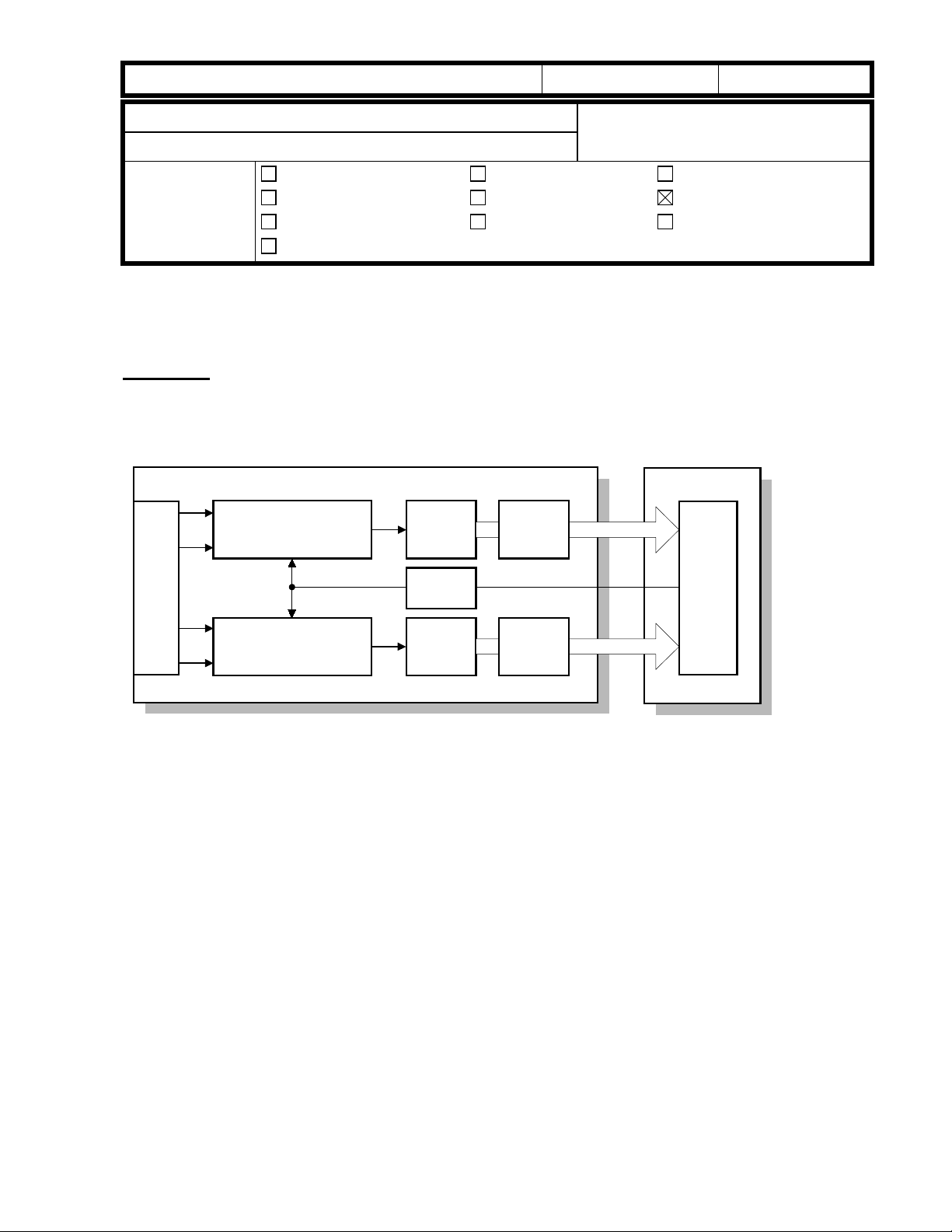
2.3.2 SBU
OS4
OS3
Analog
Processing (Last)
A/D 1
LVDS
06-Jun-00
Prepared by:
Action required
Service manual revision
Retrofit information
8-bit data
No.:
M. Tsuyuki
BICUSBU
RA293003
CCD
IPUGA
OS2
OS1
Analog
Processing (First)
A/D 2
LVDS
8-bit data
The CCD converts the light reflected from the original into an analog signal. The CCD line
has 7,500 pixels and the resolution is 600 dpi (23.6 lines/mm).
The CCD has four output lines: OS1, OS2, OS3, and OS4. OS1 and OS2 are for the first
half of the scan line (Non-operation side), and OS3 and OS4 are for the last half of the
scan line (Operation side). There are two analog processing ICs; one handles the first half
line (OS 1 and OS2) and the other handles the last half line (OS3 and OS4). The analog
processing IC performs the following operations:
1) Combines the odd and even signals into one line signal.
2) Adjust the black reference level of each CCD output channel.
3) Amplifies the analog signal from the CCD.
After the above processing, the analog signals are converted to 8-bit signals by the A/D
converter. This gives a value for each pixel on scale of 256 grades. Then, the two 8-bit
signals are sent to the BICU board through the LVDS (Low Voltage Differential Signaling).
The LVDS is a noise-resistant interface.
Page 4
!"#$% T
echnical Bulletin
PAGE: 2/3
Model:
Mojito
Date:
06-Jun-00
No.:
RA293003
Page 4-46
SP5-009: Language Selection
Please delete a sentence “After changing the setting for this SP mode, turn the main
power switch off and on”.
This SP mode is same function as “Language Priority” in UP mode.
Page 4-66
Please correct the pattern tables as follows.
Test Pattern Table (SP2902-2: Test Pattern Printing – IPU)
No. Test Pattern No. Test Pattern
0 None 7 Vertical Stripes
1 Vertical Lines (1-dot) 8 Grayscale (Vertical)
2 Vertical Lines (2-dot) 9 Grayscale (Horizontal)
3 Horizontal Lines (1-dot) 10 Cross Pattern
4 Horizontal Lines (2-dot) 11 Argyle Pattern
5 Alternating Dot Pattern 12 Frequency (Horizontal)
6 Grid Pattern (1-dot) 13 Frequency (Vertical)
Test Pattern Table (SP2902-3: Test Pattern Printing – Printing)
No. Test Pattern No. Test Pattern
0 None 13 16 Grayscale (Vertical)
1 Vertical Lines (1-dot) 14 16 Grayscale (Vertical/Horizontal)
2 Horizontal Lines (1-dot) 15 16 Grayscale (Grid)
3 Vertical Lines (2-dot) 16 Hound’s Tooth Check (1-dot 600dpi) (Cross Stitch)
4 Horizontal Lines (2-dot) 17 Hound’s Tooth Check (1-dot 400dpi) (Cross Stitch)
5 Grid Pattern (1-dot) 18 Horizontal Line (1-dot) (Reverse Order of LD1 and LD2)
6 Grid Pattern (1-dot pair) 19 Grid Pattern (1-dot) (Reverse Order of LD1 and LD2)
7 Independent Pattern 20 Grid Pattern (1-dot pair) (Reverse Order of LD1 and LD2)
8 Full Dot Pattern 21 Independent Pattern (1-dot) (Reverse Order of LD1 and LD2)
9 Black Band 22 Blank Page
10 Trimming Area 23 Grid Pattern (1-dot) (Overlaying Outside Data)
11 Argyle Pattern 24 Trimming Area (Overlaying Outside Data)
12 16 Grayscale (Horizontal)
Page 4-78
“NOTE” after step 6:
Please delete SP7-007. SP7-007 is not used in this model.
Page 5

!"#$% T
echnical Bulletin
PAGE: 3/3
Model:
Page 7-18
Please delete SC388. This number is not used in this model.
Laser Beam Pitch Adjustment
The “Laser Beam Pitch Adjustment” procedure is same as SP5. However, SP mode
numbers are changed as follows.
SP2-902-2 no.12: IPU Test Pattern – Cross Stitch – 400dpi
SP2-902-3 no.17: Printing Test Pattern - Hound’s Tooth Check (1-dot 400dpi) (Cross
SP2-902-2 no.13: IPU Test Pattern – Cross Stitch – 600dpi
SP2-902-3 no.16: Printing Test Pattern - Hound’s Tooth Check (1-dot 600dpi) (Cross
Mojito
⇓
Stitch)
⇓
Stitch)
Date:
06-Jun-00
No.:
RA293003
Page 6

!"#$% T
echnical Bulletin
PAGE: 1/7
Model:
Subject:
From:
Mojito
Service Manual
Technical Services Dept., GTS Division
Classification:
Troubleshooting
Mechanical
Paper path
Other ( )
Part information
Electrical
Transmit/receive
Date:
08-Jun-00
Prepared by:
No.:
RA293004
M. Tsuyuki
Action required
Service manual revision
Retrofit information
Please add the following SC descriptions to your service manuals.
Page 7-34
SC740: 1000-sheet finisher error in finisher area
- Definition – [B]
Note: When this SC is displayed, check SP7-902 (SC details). The first 2 digits indicate
the type of error.
Example: 740 0100000000000000
01: Shutter movement error
1) The shutter position switch does not turn on within 1 second after the transport motor
starts to turn in reverse.
2) The shutter sensor does not deactivate within 1 second after the transport motor
starts to turn in reverse.
3) The shutter position switch is off when the shift tray safety switch is off.
- Possible causes -
• Transport motor defective
• Shutter position switch defective
• Shift tray safety switch defective
02: Exit motor error
1) After the exit motor turns on, the exit motor sensor does not send the proper signal to
the finisher board.
2) The exit motor sensor does not send the clock signal to the finisher board for a certain
period while the exit motor is on.
- Possible causes -
• Exit motor defective
• Exit motor sensor defective
Page 7

!"#$% T
echnical Bulletin
PAGE: 2/7
Model:
03: Upper exit plate movement error
1) The upper exit guide 2 switch does not turn on within 1 s after the guide plate motor
2) The upper exit guide sensor does not activate within 1 s after the guide plate motor
3) The upper exit guide 2 switch does not turn on when the shift tray safety switch is off.
- Possible causes -
04: Jogger motor error
1) After the jogger motor turns on to move the jogger fence from its home position, the
Mojito
turns on.
turns on.
• Guide plate motor defective
• Upper exit guide 2 switch defective
• Upper exit guide sensor defective
• Shift tray safety switch defective
jogger HP sensor does not deactivate within 2 s.
Date:
08-Jun-00
No.:
RA293004
2) After the jogger motor turns on to return the jogger fence to its home position, the
jogger HP sensor does not activate within 2 s.
- Possible causes -
• Jogger motor defective
• Jogger HP sensor defective
05: Stapler motor error
1) After the stapler motor turns on to move the stapler unit from its home position, the
stapler unit HP sensor does not deactivate within 4 s.
2) After the stapler motor turns on to return the stapler unit to its home position, the
stapler unit HP sensor does not activate within 4 s.
- Possible causes -
• Stapler motor defective
• Stapler unit HP sensor defective
Page 8

!"#$% T
echnical Bulletin
PAGE: 3/7
Model:
06: Staple hammer motor error
1) The staple hammer HP sensor does not deactivate within 0.5 s after the staple
2) The staple hammer HP sensor does not activate within 0.5 s after the staple hammer
- Possible causes -
07: Tray lift motor error
1) The tray lift motor does not stop within 15 s after being turned on.
2) The shift tray HP sensor does not activate within 15 s after the tray lift motor turns on.
3) The shift tray upper limit switch turns on while the shift tray is being raised.
4) Lift motor sensors 1 and 2 do not send the clock signals to the finisher board every
Mojito
hammer motor turns on.
motor turns on.
• Staple hammer motor defective
• Staple hammer HP sensor defective
200 ms while the tray lift motor is on.
Date:
08-Jun-00
No.:
RA293004
- Possible causes -
• Tray lift motor defective
• Lift motor sensor 1 defective
• Lift motor sensor 2 defective
• Shift tray HP sensor defective
• Shift tray upper limit switch defective
08: Shift tray height sensor error
1) Abnormal communication data between finisher board and shift tray height sensor.
2) No communication between finisher board and shift tray height sensor for a certain
period.
3) The finisher board detects a connection error with the connector for the shift tray
height sensor.
4) Adjustment error during shift tray height sensor adjustment.
- Possible causes -
• Shift tray height sensor defective
• Finisher board defective
Page 9

!"#$% T
echnical Bulletin
PAGE: 4/7
Model:
09: Back-up RAM error
- Possible causes -
0A: Communication error
Communication error between finisher board and booklet unit board.
- Possible causes -
SC741: 1000-sheet finisher error in saddle stitching area
Mojito
The check sum is abnormal when the main switch is turned on.
• Finisher board defective
• Finisher board defective
• Booklet unit board defective
• Poor cable connection
Date:
08-Jun-00
No.:
RA293004
- Definition – [B]
Note: When this SC is displayed, check SP7-902 (SC details. The first 2 digits indicate the
type of error.
Example: 741 0100000000000000
01: Positioning plate motor error
1) After the positioning plate motor turns on to move the positioning plate from its home
position, the positioning plate HP sensor does not deactivate within 1.25 s.
2) After the positioning plate motor turns on to return the positioning plate to its home
position, the positioning plate HP sensor does not activate within 1 s.
- Possible causes -
• Positioning plate motor defective
• Positioning plate HP sensor defective
Page 10

!"#$% T
echnical Bulletin
PAGE: 5/7
Model:
02: Folder roller motor error
1) The folder roller motor sensor doesn’t send a clock pulse to the booklet unit board
- Possible causes -
03: Shutter guide motor error
1) After the shutter guide motor turns on to move the shutter guide from its home
2) After the shutter guide motor turns on to return the shutter guide to its home position,
- Possible causes -
Mojito
within a certain period after the folder roller motor turns on.
• Folder roller motor defective
• Folder roller motor sensor defective
position, the shutter guide HP sensor does not deactivate within 0.4 s.
the shutter guide HP sensor does not activate within 1 s.
• Shutter guide motor defective
Date:
08-Jun-00
No.:
RA293004
• Shutter guide HP sensor defective
04: Booklet jogger motor error
1) After the booklet jogger motor turns on to move the booklet jogger plate from its home
position, the booklet jogger HP sensor does not deactivate within 0.5 s.
2) After the booklet jogger motor turns on to return the booklet jogger plate to its home
position, the booklet jogger HP sensor does not activate within 1 s.
- Possible causes -
• Booklet jogger motor defective
• Booklet jogger HP sensor defective
Page 11

!"#$% T
echnical Bulletin
PAGE: 6/7
Model:
05: Stapler motor error
1) The front staple hammer HP switch does not turn off within 0.5 s after the front stapler
2) The front staple hammer HP switch does not turn on within 0.5 s after the front stapler
3) The rear staple hammer HP switch does not turn off within 0.5 s after the rear stapler
4) The rear staple hammer HP switch does not turn on within 0.5 s after the rear stapler
- Possible causes -
Mojito
motor turns on.
motor turns on during jam recovery.
motor turns on.
motor turns on during jam recovery.
• Front stapler motor defective
• Front staple hammer HP switch defective
• Rear stapler motor defective
• Rear staple hammer HP switch defective
Date:
08-Jun-00
No.:
RA293004
06: Folder plate motor error
1) After the folder plate motor turns on to return the folder plate to its home position, the
folder plate HP sensor does not activate within 0.3 s.
2) After the folder plate motor turns on to move the folder plate from its home position,
the folder plate HP sensor does not deactivate within 0.3 s.
3) After the folder plate motor turns on to return the folder plate to its home position, the
folder plate return sensor does not deactivate within 0.3 s.
4) The folder plate return sensor does not activate within 0.3 s after the HP sensor
deactivates.
5) The pulse count from the folder plate motor sensor is lower than the target minimum.
- Possible causes -
• Folder plate motor defective
• Folder plate HP sensor defective
• Folder plate return sensor defective
• Folder plate motor sensor defective
Page 12

!"#$% T
echnical Bulletin
PAGE: 7/7
Model:
07: Connector error
1) The connector of the shutter guide HP sensor is not connected.
2) The connector of the folder plate HP sensor is not connected.
3) The connector of the folder plate return sensor is not connected.
- Possible causes -
08: Switch error
1) When the booklet entrance guide sensor, lower door sensor, and booklet exit cover
2) When the booklet entrance guide sensor, lower door sensor, and booklet exit cover
Mojito
• Poor connection or no connection of the shutter guide HP sensor connector
• Poor connection or no connection of the folder plate HP sensor connector
• Poor connection or no connection of the folder plate return sensor connector
sensor are all activated (doors closed), the booklet entrance guide safety switch does
not turn on within 1 s after a copy job or warm-up idling begins.
sensor are all activated (doors closed), the lower door safety switch does not turn on
within 1 s after a copy job or warm-up idling begins.
Date:
08-Jun-00
No.:
RA293004
3) When the booklet entrance guide sensor, lower door sensor, and booklet exit cover
sensor are all activated (doors closed), the booklet exit cover safety switch does not
turn on within 1 s after a copy job or warm-up idling begins.
- Possible causes -
• Booklet entrance guide safety switch defective
• Lower door safety switch defective
• Booklet exit cover safety switch defective
Page 13
echnical Bulletin
T
PAGE: 1/3
Model:
Subject:
From:
Mojito
BICU Firmware Modification History
Technical Services Dept., GTS Division
Classification:
Troubleshooting
Mechanical
Paper path
Other ( )
Part information
Electrical
Transmit/receive
Date:
09-Jun-00
Prepared by:
No.:
RA293005
F. Noguchi
Action required
Service manual revision
Retrofit information
Modification history of the BICU firmware
As there are five types of the firmware, use the appropriate one for each customer.
Destination Part Number Model Codes/Languages
A292 -15, -17, A293 -15, -17America A293 7553C
US English, French, Spanish
A292 -19, -22, -26, -27, -29, A293 -22, -26, -27, -29Eu1_Asia A293 7653C
English, French, Spanish, German, Italian, Dutch
A292 -22, -26, -27, A293 -22, -26, -27Eu2 A293 7564
English, German, Swedish, Norwegian, Danish, Finnish
A292 -22, -26, -27, A293 -22, -26, -27Eu3 A293 7565
English, German, Portuguese, Polish, Hungarian, Czech
A292 -14, -24, A293 –14, -24Eu3 (Lanier) A293 7566
English, German, Portuguese, Polish, Czech
Destination/
Part Number
Version/Suffix
3.1 C C - - -
America
A293 7553
Eu1_Asia
A293 7653
Eu2
A293 7564
Eu3
A293 7565
Eu3(Lanier)
A293 7566
Page 14

echnical Bulletin
T
PAGE: 2/3
Model:
Mojito
Date:
09-Jun-00
No.:
RA293005
Version 3.1
Destination/ America Eu1_Asia Eu2 Eu3 Eu3 (Lanier)
Part Number A293 7553C A293 7653C A293 7564 A293 7565 A293 7566
Note:
1) The LCDC ROM A2935203C is required for BICU firmware version 3.1 (A293 7564,
A293 7565 and A293 7566).
2) Version 3.1 requires the printer controller.
1. Language
The following items have been changed from English to the language selected:
1) Stamp Setting
Note: For Portuguese and Polish, the Stamp setting is still displayed in English.
The correction for this will be included in the next software update.
2) Language Priority button
2. A3/DLT Double Count corrected for copy counter and printer counter
When making A3/DLT copies, the copy and printer counters do not count up by 2,
even if A3/DLT Double Count has been set.
Note: The total counter correctly counts up by 2.
3. Key counter in connect copy mode
When the key counter is removed from the machine during a copy job in connect copy mode,
both copiers will stop and display “paper jam”.
4. Slip-Sheet Mode
It is possible to select “Copy” or “Blank” from the operation panel in Slip-Sheet Mode.
5. Mailbox
The software has been modified so that the correct picture indicator is displayed when the
mailbox door is open.
Note: The incorrect indicator was displayed when the Mailbox was the only option installed.
6. Conditions for reverse drum rotation
To reduce the load on the units around the drum, the cycle for reverse drum rotation has been
changed as follows:
New: The drum is turned in reverse at the end of a copy job if the cumulative running time for
the drum has reached or exceeded 4 minutes.
Old: The drum turns in reverse at the end of every copy job.
Page 15
echnical Bulletin
T
PAGE: 3/3
Model:
Mojito
Date:
09-Jun-00
No.:
RA293005
7. New SP Mode for B302 Finisher: SP6119
SP6119 has been added to enable the punch function for Thick Paper Mode.
Note:
1. Before enabling SP6119, please be sure that the customer is aware of the specific range of
paper weights that can be used with this mode.
2. Do not enable this mode if the customer is using OHP transparencies.
Mode No. Function Setting
Punch Function Enabled (Thick Paper)6119
* Selects whether the punch function
is enabled or not in thick paper
mode.
No: Disable
Yes: Enable
8. 8K/16K Paper Size (China/Taiwan)
8K/16K paper size can be fed from Trays 2 and 3 by selecting 3:CH in SP5131 “Paper Size
Type Selection”.
Note: The factory default for SP5131 is 3:CH in models for China and Taiwan.
Mode No. Function Setting
Paper Size Type Selection5131
* Refer to the service manual. 0: JP
1: NA
2: EU
3: CH
9. Copy Settings preserved when entering Energy Saver Mode
The software has been modified so that the selected copy settings are not reset when the
machine enters Energy Saver Mode.
10. New SP Mode added to enable Margin Per Original function (SP5924)
The settings for this mode are as follows:
Mode No. Function Setting
5924
Margin Per Original
1 Margin Per Original * Selects whether or not Margin Per Original
is enabled.
No : Images are shifted with a binding
margin during image writing.
Yes: The margin is applied during
scanning.
NOTE: After Yes has been selected, the
“per original” key is displayed. This key
must be pressed to activate the mode.
2 Per Original Priority * Selects whether or not Margin Per Original
is enabled as the default.
This setting is given priority over
5924-1.
Note: 1) When this mode is enabled, the ADF feed interval is longer.
2) Although it is possible to “adjust” the margins at the operation panel for Sample
Copies, the adjustment itself is not applied to the samples.
3) The following modes cannot be used with Margin Per Original: Booklet, Magazine,
Combine, Double copy, Image repeat.
No
Yes
On
Off
Page 16

echnical Bulletin
T
PAGE: 1/2
Model:
Subject:
From:
Mojito
NV-RAM Minus Counter Replacement Procedure
Technical Services Dept., GTS Division
Classification:
Troubleshooting
Mechanical
Paper path
Other ( )
Part information
Electrical
Transmit/receive
Date:
27-Jun-00
Prepared by:
No.:
RA293006
F. Noguchi
Action required
Service manual revision
Retrofit information
NV-RAM replacement procedure
Case 1: NV-RAM is not defective.
1. Print out all SMC data lists (SP 5-990-1).
2. Upload the NVRAM data from the BICU to the flash memory card (SP 5-824).
3. Turn the main power switch off.
4. Replace the NV–RAM Minus Counter.
5. Perform memory all clear (SP 5-801).
5. Turn the main power switch off and on.
6. Calibrate the LCD touch panel.
7. Input the machine serial number (SP 5-811).
9. Download the NVRAM data from the flash memory card to the BICU (SP 5-825).
Or, referring to the SMC data lists, re-enter any value which has been changed from
its factory setting.
10. Download the stamp data from the flash memory card (SP5-829).
11. Check the copy quality and the paper path and do any necessary adjustments.
Page 17

echnical Bulletin
T
PAGE: 2/2
Model:
Case 2: NV-RAM is defective
1. If possible, print out all SMC data lists (SP 5-990-1).
2. Turn the main power switch off.
3. Replace the NV–RAM Minus Counter.
4. Replace the developer because the TD initial data is missing if the NV-RAM is
5. Perform memory all clear (SP 5-801).
6. Turn the main power switch off and on.
7. Calibrate the LCD touch panel.
8. Perform the TD initial setting (SP 2-963).
9. Input the machine serial number (SP 5-811).
10. Adjust the laser beam pitch (SP 2-109).
11. Perform the printer and scanner registration adjustments.
12. Referring to the SMC data lists, re-enter any value which has been changed from its
13. Download the stamp data from the flash memory card (SP5-829).
14. Perform SP 3-001-2 (ID Sensor Initial Setting) and SP 4-911-1 (HDD media test).
15. Check the copy quality and the paper path and do any necessary adjustments.
Mojito
defective.
Note: Do this step before the machine automatically starts the Auto Process Control
(within approximately 2 minutes after the main switch is turned on).
(See Replacement and Adjustment – Copy Image - Adjustments)
factory setting.
Note: Be sure that the customer is aware that the HDD media test will delete copy
server and stamp data on the hard drives.
Date:
27-Jun-00
No.:
RA293006
Page 18
Reissued: 06-Jul-00
echnical Bulletin
T
PAGE: 1/3
Model:
Mojito
Date:
09-Jun-00
No.:
RA293005a
RTB Correction
Version 3.5 and 3.5.1 has been added.
Subject:
From:
BICU Firmware Modification History
Technical Services Dept., GTS Division
Classification:
Troubleshooting
Mechanical
Paper path
Other ( )
Part information
Electrical
Transmit/receive
Prepared by:
Action required
Service manual revision
Retrofit information
F. Noguchi
Modification history of the BICU firmware – versions 3.5 and 3.5.1 only (for earlier
versions, see previous RTBs).
As there are five types of the firmware, use an appropriate one for each customer.
Destination Part Number Model Codes/Languages
A292 -15, -17, A293 -15, -17America A293 7553
US English, French, Spanish
A292 -19, -22, -26, -27, -29, A293 -22, -26, -27, -29Eu1_Asia A293 7653
English, French, Spanish, German, Italian, Dutch
A292 -22, -26, -27, A293 -22, -26, -27Eu2 A293 7564
English, German, Swedish, Norwegian, Danish, Finnish
A292 -22, -26, -27, A293 -22, -26, -27Eu3 A293 7565
English, German, Portuguese, Polish, Hungarian, Czech
A292 -14, -24, A293 –14, -24Eu3(Lanier) A293 7566
English, German, Portuguese, Polish, Czech
Destination/
Part Number
Version/Suffix
3.1 C C - - - 09-Jun-00
3.5 D D A A A 06-Jul-00
3.5.1 E E B B B 06-Jul-00
America
A293 7553
Eu1_Asia
A293 7653
Eu2
A293 7564
Eu3
A293 7565
Eu3(Lanier)
A293 7566
RTB issue
date
Page 19
Reissued: 06-Jul-00
echnical Bulletin
T
PAGE: 2/3
Model:
Mojito
Date:
09-Jun-00
No.:
RA293005a
Version 3.5.1
Destination/ America Eu1_Asia Eu2 Eu3 Eu3(Lanier)
Part Number A293 7553E A293 7653E A293 7564B A293 7565B A293 7566B
1. New Copy Feature and SP Mode (SP5971) Added
1) New Copy Feature: Enhance Density Mode
This feature has been added to ensure that image density does not drop while making
multiple copies of originals with a high percentage of solid black areas.
To set thebeffective original density and number of copies for multi-copy mode, use SP5971
(see below).
To add the Enhance Density key to the display panel and to control the level, do the
following procedure:
(1) Press the User Tools/Counter key.
(2) Press the Copy/Document Server Features Key.
(3) Open General Features, screen 3/3.
(4) Select one of the Shortcut Keys from F1 – F5.
(5) Register the Enhance Density Key.
(6) Open General Features, screen 1/3.
(7) Select the setting for Enhance Density Level.
High: Vt+0.6
Medium: Vt+0.4 (default)
Low: Vt+0.2
2) New SP Mode: SP5971 (Enhance Copy Setting):
The following settings apply to Enhance Density Mode:
Mode No. Function Setting
5971
2. Paper jam in finisher (B302) + Printer Mode
Depending on the printer mode settings, jams can occur in the finisher when continuous print
jobs are shifted alternately between the proof and shift trays.
The machine cannot switch fast enough between the two paper paths in these cases. The
interval between jobs has been slightly increased to allow the machine enough time to make
the switch.
3. Fusing Unit Fan Motor Off-Timing Change
To ensure that hot air around the toner bottle is removed properly, the fusing unit fan motor
will be kept on whenever 24V is being supplied.
Therefore, it will turn off only when the main switch or operation switch is turned off or when
the machine is shut down by the Auto-Off function.
Enhance Copy Setting
2 Effective Original
Density
3 Effective Multiple
Copy
* Selects the effective original
density level for multi-copy mode.
* Selects the number of multiple
copies for multi-copy mode.
1 ∼ 60%
1% step
4%
1 ∼ 50sheets
1 sheet step
3 sheets
4. Wording Correction
Some display language words and phrases have been corrected/improved.
Page 20

Reissued: 06-Jul-00
echnical Bulletin
T
PAGE: 3/3
Model:
Version 3.5
Destination/ America Eu1_Asia Eu2 Eu3 Eu3(Lanier)
Part Number A293 7553D A293 7653D A293 7564A A293 7565A A293 7566A
Note: This is information only, as version3.5 was not released to the field and was not used in
Mojito
any product machine.
Date:
09-Jun-00
No.:
RA293005a
Page 21
!"#$% T
echnical Bulletin
PAGE: 1/5
Model:
Subject:
From:
Mojito
SC740 and Jam indicator turns on.
Technical Services Dept., GTS Division
Classification:
Troubleshooting
Mechanical
Paper path
Other ( )
Part information
Electrical
Transmit/receive
Date:
04-Jul-00
Prepared by:
No.:
RA293007
M. Tsuyuki
Action required
Service manual revision
Retrofit information
Some booklet finishers (A763) may exhibit the following problem. Please check the
machine at installation or at the next customer site visit.
SYMPTOM
When making copies in staple mode, an IC on the finisher board shorts and SC740 is
displayed. After the main switch is turn off and on, a jam is indicated.
CAUSE
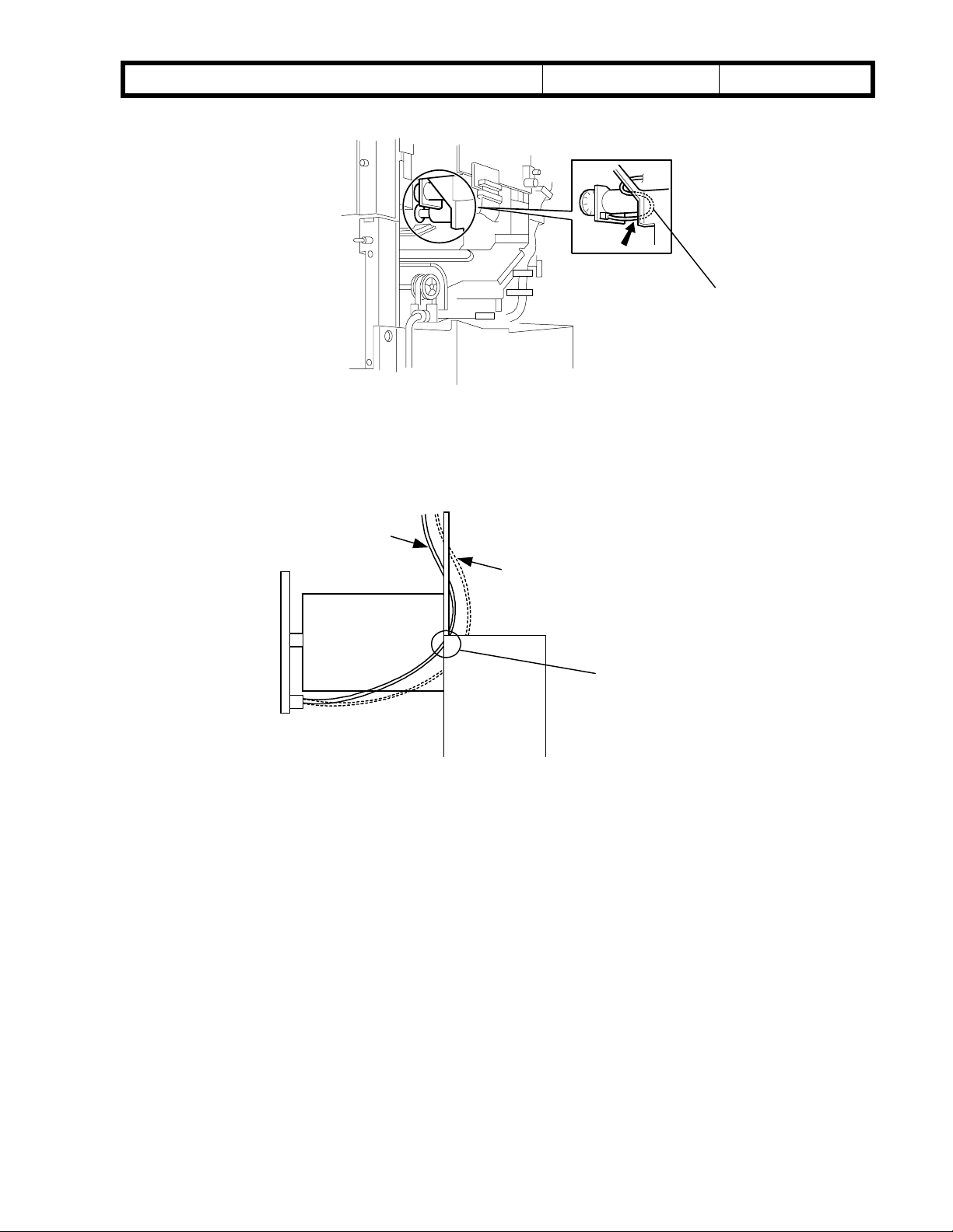
The cable of the guide plate motor is caught between the guide plate unit and frame. In the
worst case, the cable covering peels off and the +24V line is shorted to ground. These two
factors combine to cause the finisher board to be damaged.
ACTION
[A]
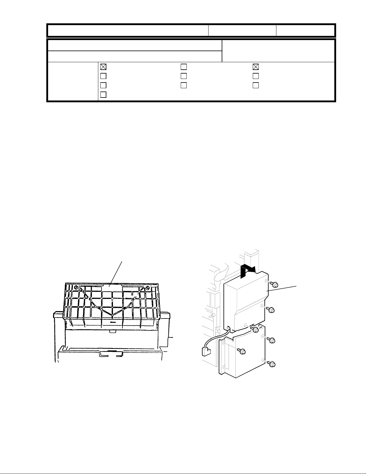
1. Hold up the proof tray and open the top cover [A].
[B]
2. Unhook the upper rear cover [B] and remove it (3 screws).
Page 22
!"#$% T
echnical Bulletin
PAGE: 2/5
Model:
3. Check to see if the cable [C] is caught.
4. If it is not caught, the finisher is Ok. If it is caught, go on to the next step.
Mojito
Date:
04-Jul-00
NG
No.:
[C]
RA293007
NG
OK
[D]
5. If the cable is caught at area [D], go on to the next step. If not, the finisher is OK.
Page 23
!"#$% T
echnical Bulletin
PAGE: 3/5
Model:
[E]
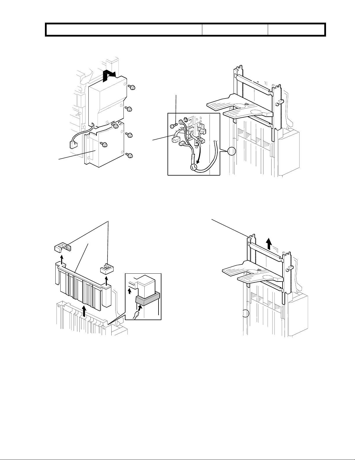
6. Remove the lower rear cover [E] (4 screws).
Mojito
[G]
[F]
Date:
04-Jul-00
No.:
RA293007
7. Disconnect the connector [F] and remove the grounding wire [G] (1 screw).
[H]
[I]
8. Unhook the two stoppers [H] and remove them.
[J]
9. Remove the slide guide [I] by pulling it up.
10. Remove the shift tray unit [J] by pulling it up.
Page 24

!"#$% T
echnical Bulletin
PAGE: 4/5
Model:
10. Remove the upper shift guide [K] (6 screws (5 x M4, 1 x M3).
11. Remove the lower shift guide [L] (2 connectors, 6 screws [3 x M4, 3 x M3]).
Mojito
[K]
[L]
Date:
04-Jul-00
No.:
RA293007
[M]
12. Loosen the rear side screws [M] of the exit unit.
13. Free the cable [N].
14. Check the surface of the cable.
15. If the cable wires are visible, wrap them with vinyl tape.
[N]
Page 25

!"#$% T
echnical Bulletin
PAGE: 5/5
Model:
16. Reassemble the machine.
Mojito
[O]
Note: When reinstalling the shift tray unit, release the clutch gear [O] of the tray lift
motor by carefully inserting a screwdriver.
Date:
04-Jul-00
No.:
RA293007
COUNTERMEASURE
The length of the cable has been decreased and the route of the cable has been modified.
Serial numbers of finishers which may have this problem:
Model Code Serial Number:
A763-14 : From first production to L0740030077
A763-17 : From first production to H5000400375
A763-22 : From first production to H5000300440
A763-26 : From first production to 4D80300090
A763-27 : From first production to H5000300571
Page 26

!"#$% T
echnical Bulletin
PAGE: 1/2
Model:
Subject:
From:
Mojito
Low ID
Technical Services Dept., GTS Division
Classification:
Troubleshooting
Mechanical
Paper path
Other ( )
Part information
Electrical
Transmit/receive
Date:
06-Jul-00
Prepared by:
No.:
RA293008
M. Tsuyuki
Action required
Service manual revision
Retrofit information
SYMPTOM
Low image density on copies made by low CV machines around 20 to 30K after
installation.
CAUSE
The fusing fan motor stops when the low power timer runs out (60 s) and the machine
enters Energy Saver Mode. Because the fusing lamp remains on in order to maintain hot
roller temperature, the temperature of the areas surrounding the unit rises. The resulting
heat can damage the toner that is stored in the bottle above the fusing unit, causing some
of the toner’s constituents to separate out. The altered toner is then sent to the
development unit and is mixed in with the developer, causing developer chargeability to
drop. This results in low image density on copies.
This heat damage occurs on low CV machines, as the toner remains in the bottle for
extended periods of time.
ACTION
Newly installed machines:
Please upgrade the BICU firmware to ver 3.5.1 at installation.
Field machines which have no low ID problem:
Please upgrade the BICU firmware to ver 3.5.1 at the next field visit.
Field machines which have a low ID problem:
1. Upgrade the BICU firmware to ver 3.5.1.
2. Replace the developer.
3. Replace the toner bottle.
4. Clean the toner from the toner hopper.
Page 27

!"#$% T
echnical Bulletin
PAGE: 2/2
Model:
Mojito
Date:
06-Jul-00
No.:
RA293008
COUNTERMEASURE
1. Firmware:
The off-timing of the fusing fan motor has been delayed, so that it will remove the hot air
around the toner bottle.
2. Hardware:
As an added measure, a heat insulator will be installed between the front frame of the
scanner unit and the toner bottle to ensure that the toner is not damaged, even if the
internal temperature should rise.
Page 28

Reissued: 13-Nov-00
echnical Bulletin
T
PAGE: 1/2
Model:
Mojito
Date:
17-Jul-00
No.:
RA293009a
RTB Correction
The items in bold italics have been corrected.
Subject:
From:
SC 124,501,502,503,362(220-240V version only)
Technical Services Dept., GTS Division
Classification:
Troubleshooting
Mechanical
Paper path
Other ( )
Part information
Electrical
Transmit/receive
Prepared by:
Action required
Service manual revision
Retrofit information
F. Noguchi
SYMPTOM
One of the following SCs is activated when the power is turned on by the weekly timer or
by the operation switch (upper right of the panel):
SC124: Scanner motor encoder error SC501: 1st tray lift malfunction
SC335: Polygonal mirror motor error 1 SC502: 2nd tray lift malfunction
SC362: Hard disk detector error SC503: 3rd tray lift malfunction
SC493: Exhaust fan motor lock SC520: Duplex jogger motor error 1
SC494: Fusing exhaust fan motor lock
CAUSE
When the power is turned on, the supply of voltage through the 24V line is slow.
FIELD ACTION
The occurrence rate is predicted to be extremely low because the range of tolerance for
the start-up current in 220V machine PSUs is approximately +/- 20%. If you receive reports
of any of the SCs mentioned above, please do the following procedure:
1. Set the machine to turn off with the weekly timer.
2. After the machine has turned off, turn the operation switch on and off at least ten times.
3. When any of the SCs listed above is activated, please replace the PSU board.
If none are activated, please check other possible causes for the SCs reported.
Note: The PSU boards themselves cannot be modified in the field. Therefore, all PSUs
now in service parts stock are either modified units or previous units that were found
to have no problems (see below for details). The part number for the PSU has not
been changed.
Page 29

Reissued: 13-Nov-00
echnical Bulletin
T
PAGE: 2/2
Model:
COUNTERMEASURE
Temporary
The PSUs in service parts stock have been checked and the units with defective boards
have been sorted out using the IC301-9 output signatures.
Permanent
An 820 Ohm (1/4w) resistor has been added to the PSU board. In order to do this,
the board pattern was changed.
Mojito
Date:
17-Jul-00
No.:
RA293009a
Added
820 Ohms
Cut-in serial Numbers
The modified PSUs have been used in production machines from the following serial
numbers:
Temporary Permanent
A292
A293
-22 ----
-24
-26 ----
-27
-29
-22 ----
-24
L0710060126 ∼ L0710070132 ∼
H4700500599 ∼ H4700600371 ∼
H4700500616 ∼ H4700600001 ∼
L0720060126 ∼ L0720070105 ∼
H4700600123 ∼
4D60600001 ∼
H4800600001 ∼
-26 ----
-27
-29
H4800500101 ∼ H4800600173 ∼
H4800500559 ∼ H4800600426 ∼
4D50600001 ∼
Page 30

echnical Bulletin
T
PAGE: 1/3
Model:
0M
Subject:
From:
Mojito
Service manual
Technical Services Dept., GTS Division
Classification:
Troubleshooting
Mechanical
Paper path
Other ( )
Part information
Electrical
Transmit/receive
Date:
11-Aug-00
Prepared by:
No.:
RA293010
F. Noguchi
Action required
Service manual revision
Retrofit information
Please correct or add the following to your service manuals:
Page 3-27 Correction
3.5.2 PUNCH UNIT INSTALLATION
When attaching the punch unit (A812) to the SR740 finisher (B312), it is not necessary
to change the dip switch setting. From the B312 model, the dip switch is located on the
A812 unit's punch drive board and is set at the factory.
Incorrect:
10. When a three-punch-hole-unit is installed: Change switch 1 of DIP SW 100 on
the finisher control board to ON.
Correct:
10. When a three-punch-hole-unit is installed: Check to see that switch 1 of DIP SW
100 on the punch drive board has been set to ON.
Page 4-61 Addition
4.2.2 SERVICE PROGRAM MODE TABLES
The following SP modes have been added from the 1st production.
7-504 Copy Jam Counter by Jam Location
41 SR750
Booklet Exit
sensor
(On check)
42 SR750
Booklet Exit
sensor
(Off check)
43 SR750
Booklet staple
jam
*
*
*
Page 31

echnical Bulletin
T
PAGE: 2/3
Model:
0M
Page 4-76 Addition
4.3 PROGRAM AND DATA Downloading to the SBICU
The downloading procedure for the Mojito is the same as for the SP5.
Downloading to the SBICU
1. Turn off the main power switch.
2. Remove the flash memory card cover [A].
3. Insert the flash memory card [B] into the card slot.
4. Turn on the main power switch.
5. Press “Install”. The machine erases the current software, then writes the new
Mojito
NOTE: Make sure that the surface marked “A” faces upwards.
software to the SBICU. This takes about 200 seconds.
If downloading fails, an error message appears on the display. At this time, press the
“OK” key to attempt the download again.
Date:
11-Aug-00
No.:
RA293010
Page 32

echnical Bulletin
T
PAGE: 3/3
Model:
0M
Mojito
Page A763-1 Correction
1.1 SPECIFICATIONS
Incorrect
Paper Capacity (80 g/m2, 20 lb):
Tray Modes Paper size Capacity
Proof tray
Shift tray
No staple
Staple
One size
Mixed sizes
Date:
A4-S, LT-S or shorter 150 sheets
A4-L, LT-L or longer 75 sheets
A4-S, LT-S or shorter
A4-L, LT-L or longer
A4-S, LT-S or shorter
A4-L, LT-L or longer
1-5 sheets 25 sets
6-10 sheets 15 setsStaple tray
11-15 sheets 10 sets
(-L”: Lengthwise ,-S: Sideways)
11-Aug-00
1000 sheets
500 sheet
750 sheets
500 sheets
No.:
RA293010
Correct
Paper Capacity (80 g/m2, 20 lb):
Tray Modes Paper size Capacity
Proof tray
Shift tray
* The machine will inform the operator that the tray is full when any of the listed
conditions are met (whichever occurs first).
No staple
Staple
One size
Mixed sizes
A4-S, LT-S or shorter 150 sheets
A4-L, LT-L or longer 75 sheets
A4-S, LT-S or shorter
A4-L, LT-L or longer
A4-S, LT-S or shorter
A4-L, LT-L or longer
1-5 sheets 25 sets
6-10 sheets 15 setsStaple tray
11-15 sheets 10 sets
(-L”: Lengthwise ,-S: Sideways)
147mm stack height
or 1000 sheets (*)
74mm stack height
or 500 sheet (*)
110mm stack height
or 30 sets
or 750 sheets (*)
74mm stack height
or 30 sets
or 500 sheets (*)
Page 33

echnical Bulletin
T
PAGE: 1/2
Model:
Subject:
From:
Mojito
Installation Procedure for Copy Tray Tape 700
Technical Services Dept., GTS Division
Classification:
Troubleshooting
Mechanical
Paper path
Other ( )
Part information
Electrical
Transmit/receive
Date:
Installation procedure for the Copy Tray Type 700
1. Accessory check
Check the accessories in the box against the following list.
Description Q’ty
1) Copy Tray ……………………………………………. 1
2) Tray Paper Limit Sensor Assembly..…..………….. 1
3) Cap – φ22 …………………………………….……… 4
4) Connector Cap …………………..…………..……… 1
22-Aug-00
Prepared by:
Action required
Service manual revision
Retrofit information
No.:
F. Noguchi
RA293011
5) Philips Tapping Screw – M4x8………… ………… 2
2. Installation Procedure
1) Remove the left cover [A] (2 screws).
[A]
2) Slide the collars (black) [B] into the holes in the
rubber rollers [C] of the exit drive roller.
[C]
[B]
[C]
Page 34

echnical Bulletin
T
PAGE: 2/2
Model:
3) Remove the shorting connector [A].
4) Install the tray paper limit sensor
Mojito
assembly [B].
Date:
22-Aug-00
[A]
[B]
No.:
RA293011
5) Reinstall the left cover.
6) Install the four caps (φ22) [C] and
the connector cap [D].
7) Install the copy tray [E].
[E]
[D]
[C]
Page 35

Reissued: 30-Aug-00
echnical Bulletin
T
PAGE: 1/5
Model:
Mojito
Date:
09-Jun-00
No.:
RA293005b
RTB Correction
Version 3.6 has been added.
Subject:
From:
BICU firmware Modification History
Technical Services Dept., GTS Division
Classification:
Troubleshooting
Mechanical
Paper path
Other ( )
Part information
Electrical
Transmit/receive
Prepared by:
Action required
Service manual revision
Retrofit information
F. Noguchi
BICU firmware modification history (version 3.6 only – for earlier modifications, see earlier
RTBs)
As there five types of the firmware, use an appropriate one for each customer.
Destination Part Number Model Codes/Languages
A292 -15, -17, A293 -15, -17America A293 7553
US English, French, Spanish
A292 -19, -22, -26, -27, -29, A293 -22, -26, -27, -29Eu1_Asia A293 7653
English, French, Spanish, German, Italian, Dutch
A292 -22, -26, -27, A293 -22, -26, -27Eu2 A293 7564
English, German, Swedish, Norwegian, Danish, Finnish
A292 -22, -26, -27, A293 -22, -26, -27Eu3 A293 7565
English, German, Portuguese, Polish, Hungarian, Czech
A292 -14, -24, A293 –14, -24Eu3(Lanier) A293 7566
English, German, Portuguese, Polish, Czech
Destination/
Part Number
Version/Suffix
3.1 C C - - - 09-Jun-00
3.5 D D A A A 06-Jul-00
3.5.1 E E B B B 06-Jul-00
3.6 F F C C C 30-Aug-00
America
A293 7553
Eu1_Asia
A293 7653
Eu2
A293 7564
Eu3
A293 7565
Eu3(Lanier)
A293 7566
RTB issue
date
Page 36

Reissued: 30-Aug-00
echnical Bulletin
T
PAGE: 2/5
Model:
Mojito
Date:
09-Jun-00
No.:
RA293005b
Version 3.6
Destination/ America Eu1_Asia Eu2 Eu3 Eu3(Lanier)
Part Number A293 7553F A293 7653F A293 7564C A293 7565C A293 7566C
1. New SP Mode (SP5970) for EB-70 (Printer controller)
The following setting applies when the EB-70 printer controller is installed.
Mode No. Function Setting
Printer Installed5970
Selects whether the EB-70 printer
controller is installed or not.
2. Some of the Image Missing in Tab Stock when Printing from the Document Server
Symptom
0: No
1: Yes
When files in the Document Server are printed onto Tab Stock, the image is not
rotated even though tab stock can be set sideways only. This is because, in the
Document Server, the documents are saved lengthwise only.
Modification
The error has been corrected.
3. Malfunction with Printer Dot Edge Parameter Setting when Printing from the Document
Server
Symptom
When edge smoothing is off, the line thickness is not changed when the printer dot edge
parameter setting (SP2114) is changed.
Modification
The error has been corrected.
Page 37

!"#$% T
echnical Bulletin
PAGE: 1/3
Model:
Subject:
From:
Mojito
Service Manual
Technical Services Dept.,GTS Division
Classification:
Troubleshooting
Mechanical
Paper path
Other ( )
Part information
Electrical
Transmit/receive
Date:
Prepared by:
Please correct your service manual as follows.
SP Modes
SP1-008 : Duplex Fence Adjustment
SP1-008-1 → Delete
SP1-008-2 → SP1-008
SP2-210 : ID Sensor Interval
Change the maximum interval from 500 copies to 200 copies.
11-Sep-00
No.:
RA293012
M. Tsuyuki
Action required
Service manual revision
Retrofit information
New SP Modes
SP2-921 : Shading correction
Designer use only.
SP5-212: Page Numbering
SP5-212-003 : Page Print Position – Side to Side
Adjusts the position (sub scan direction) of "Page Numbering" on the 2nd side when
making a duplex copy.
Range: -10 to +10mm Default: 0mm Setting: 1mm/Step
SP5-212-004 : Page Print Position – Up and Down
Adjusts the position (main scan direction) of “Page Numbering” on the 2nd side when
making a duplex copy.
Range: -10 to +10mm Default: 0mm Setting: 1mm/Step
SP5-513: PM Alarm Setting Interval
SP5-513-001: Copy Paper Based
Japanese market only
Default: 300
SP5-513-002: Original Based
Japanese market only
Default: 300
Page 38

!"#$% T
echnical Bulletin
PAGE: 2/3
Model:
SP5-514: PM Alarm on/off Setting
SP5-514-001: Copy Paper Based
Japanese market only
Default: 1
SP5-514-001: Copy Paper Based
Japanese market only
Default: 0
SP6-016: ADF Motor Speed Auto Adjustment
Adjust the speed of the feed-in motor, transport motor and feed-out motor.
Use this SP mode after replacing the main board, feed-in motor, transport motor, or
feed-out motor.
SP6-120-***: Staple Jogger Adjustment
Adjusts the jogger fence position of the staple tray.
Range: 0.0 to 1.5 Default:0.0 Setting: 0.5/step
***
001: A3
002: B4
003: A4 lengthwise
004: A4 Sideways
005: B5 lengthwise
006: B5 Sideways
007: DLT
008: LG
009: LT lengthwise
010: LT Sideways
011: Others
Mojito
Date:
11-Sep-00
No.:
RA293012
SP-7-990-***: SC990 Information
Displays the detailed information for SC990.
When SC990 has occurred, ask the technician to check this information.
***
001: File name
002: Line number
003: Value
Page 39

!"#$% T
echnical Bulletin
PAGE: 3/3
Model:
Deleted SP modes
The follwing SP modes have been deleted from mass-production machines.
SP1-110: Paper Exit – Platen Mode
SP4-903-18: Filter Level – Pale Mode
SP4-903-19: Filter Level – Generation Copy
SP4-904-3: Graduation Processing Selection – Text/Photo
SP4-904-5: Phase Control – Text
SP4-904-8: Graduation Process in Photo Area
SP4-904-9: Image Data Pass
SP4-904-12: Binary Thresh Level
SP4-904-18: Binary Dither Pattern
SP4-905-2: Image Data Path – Generation
SP4-907: Text/Photo Auto Separation Method
Mojito
Date:
11-Sep-00
No.:
RA293012
SP4-908: Text/Photo Separation Method
SP4-912-1 – 18: Text/Photo Separation Setting (All SP Modes)
SP7-830: Copy Counter by paper size
SP7-928: Document Server: Clear Copy Number of Each Job
Page 5-4
Please correct the product code of the finisher as follows;
BRAZOS-B → B312
VICTORIA → B302
TONEGAWA-B → A763
Please remove “Punch Waste Hopper” from the table of Finisher (A673).
Page 40

echnical Bulletin
T
PAGE: 1/1
Model:
Subject:
From:
Mojito
Image Quality of Half Tone and Gray Scale
Technical Services Dept., GTS Division
Classification:
Troubleshooting
Mechanical
Paper path
Other (Recommended action)
Part information
Electrical
Transmit/receive
Date:
12-Sep-00
Prepared by:
No.:
RA293013
A. Sasaki
Action required
Service manual revision
Retrofit information
SYMPTOM
The image quality of half tone or gray scale areas on printouts is not clear or sharp
enough.
ACTION
1. Recommend customers to set the Edge Smoothing function to the OFF position in
the printer driver.
The default setting of the Edge Smoothing function for each driver language and
printer controller type is as follows:
Driver Language Controller Type A Controller Type B
PCL5e ON OFF
PCL6 ON OFF
PostScript3 OFF OFF
2. Change the printer dot edge parameter in the printer SP mode (Printer SP – Settings –
Printer Dot Edge Parameter) from “Normal” (default) to “SP mode”.
Note: With this change, the print line width can be thickened. This change is valid only
when the Edge Smoothing function is set to “OFF”.
3. Change Copy SP2114 (Printer dot edge parameter setting) to the original settings.
SP Number Original Setting
SP2114-1 7
SP2114-2 7
SP2114-3 11
SP2114-4 7
4. If the customer wants an even thicker line width, change Copy SP2114 (Printer dot
edge parameter setting) from the original settings to the thicker settings.
SP Number Original Setting Thicker Setting
SP2114-1 7 10
SP2114-2 7 10
SP2114-3 11 15
SP2114-4 7 10
Note: Do not set any other combinations of the four settings other than in the above
table. Otherwise, an unexpected image appears on printouts.
This SP is valid only when the Edge Smoothing function is set to “OFF” and the
Printer Dot Edge Parameter in the printer SP mode is set to “SP mode”.
Page 41

echnical Bulletin
T
PAGE: 1/3
Model:
Subject:
From:
Mojito (Finisher)
SC729 (Punch Motor Failure)
Technical Services Dept., GTS Division
Classification:
Troubleshooting
Mechanical
Paper path
Other ( )
Part information
Electrical
Transmit/receive
Date:
06-Oct-00
Prepared by:
No.:
RA293014
S. Hizen
Action required
Service manual revision
Retrofit information
SYMPTOM
SC729 is displayed, or the mainframe does not detect the finisher.
CAUSE
1. Electrical noise generated by the drive motor affects the initial check routine of the
punch drive board firmware, such that the motor reset signal is constantly sent out. The
only units on which the symptom may occur are the USA two-punch-hole and European
four-punch-hole units.
2. The two screws securing the heat resistor to the IC on the punch drive board come
loose. As a result, the temperature of the IC becomes too high.
SOLUTION
1. The software has been changed so that the drive motor reset signal is deactivated at the
proper time, even if electrical noise occurs.
Production units:
The ROM on the finisher main board has been changed from the beginning of
September 2000 mass-production, and on some units from August mass-production.
Old ROM P/N: B302-5103F
New ROM P/N: B302-5103G
Listed below are the serial numbers for August production finishers that contain the new
modified ROM.
Note: These units are marked with yellow, circular labels next to the bar code on the
carton.
Page 42

echnical Bulletin
T
PAGE: 2/3
Model:
B302-14
L0670080009
L0670080016∼L0670080018
L0670080020∼L0670080023
L0670080025∼L0670080028
L0670080030∼L0670080035
L0670080037∼L0670080039
L0670080044∼L0670080047
L0670080049∼L0670080050
L0670080115∼L0670080151
L0670080153
L0670080155∼L0670080156
L0670080177∼L0670080178
L0670080181∼L0670080186
L0670080189∼L0670080191
L0670080193∼L0670080213
Total 99 units
B302-17
H3800800066
H3800800073∼H3800800074
H3800800082∼H3800800451
Total 373 units
Mojito (Finisher)
Date:
06-Oct-00
No.:
RA293014
B302-26: None
2 From September 2000 production of the punch units, the heat resistor securing screws
have been locked in place with an adhesive.
P/N change:
Old Punch Drive Board P/N: A812-5120
New Punch Drive Board (Heat resistor screw lock) P/N: A812-5150
Page 43

echnical Bulletin
T
PAGE: 3/3
Model:
3 Action required for field units:
3-1 Please check the two heat resistor screws when visiting the machine site and
tighten them if they are loose.
Mojito (Finisher)
Date:
Punch Motor
06-Oct-00
Make sure these
screws are tightened
securely
No.:
RA293014
Heat Sink Plate
3-2 Replace the finisher ROM only in the following finishers:
-USA: 2-punch hole unit
-Europe: 4-punch hole unit
Page 44

!"#$% T
echnical Bulletin
PAGE: 1/2
Model:
Subject:
From:
Mojito
Printer Controller (B337) System Firmware Histories
Technical Service Dept., GTS Division
Classification:
Troubleshooting
Mechanical
Paper path
Other (Information)
Part information
Electrical
Transmit/receive
Date:
10-Nov-00
Prepared by:
No.:
RA293015
A. Sasaki
Action required
Service manual revision
Retrofit information
This is to inform about the modification histories of the system firmware of Printer
Controller Type 700 (B337).
As there are two types of the firmware, use the appropriate one for the product brand.
Destination Part Number Product Codes/Brands
Generic B337 5800
Lanier B337 5814
B337-01, -10, -15, -17
Ricoh, Savin, Gestetner, Nashuatec, Rexrotary, Infotec
B337-14
Lanier
- Firmware Version and Part Number Suffix for Each Destination -
Destination Generic Lanier
Part Number B337 5800 B337 5814
Version Suffix Suffix
0.40 None None
0.43 A A
0.46 B B
- Version 0.40 -
Destination Generic Lanier
Part Number B337 5800 B337 5814
This is the first version of the mass production.
- Version 0.43 -
Destination Generic Lanier
Part Number B337 5800 A B337 5814 A
1. Blank Sheet as the Last Page of a Duplex Job with Odd-numbered Pages
Symptom
When a duplex job with odd-numbered pages is printed using the sample print function, the
second side of the last sheet is stored as a blank page.
Modification
The blank page is deleted when the file for the job is stored as a document server document.
Note
This modification is valid only with the engine firmware version 3.51 onwards.
Page 45

!"#$% T
echnical Bulletin
PAGE: 2/2
Model:
2. Error when Deleted Files are Accessed
3. Unnecessary Characters when Downloading User Defined Symset of PCL5e
4. Wait State of Flash ROM
Mojito
Symptom
An error occurs when deleted files in the deletion list of the engine are accessed.
Note
This modification is valid only with the engine firmware version 3.51 onwards.
Symptom
Unnecessary characters are also included when Downloading User Defined Symset of PCL5e.
Symptom
The Wait State of the flash ROM is valid with not only 70-ns ROM but also 90-ns ROM.
Date:
10-Nov-00
No.:
RA293015
- Version 0.46 -
Destination Generic Lanier
Part Number B337 5800 B B337 5814 B
1. Measure for 10” x 14” Paper.
2. Symptom
A print job with more than 1000 pages stops printing.
3. Symptom
The user tools are not accessible and SC955 occurs if a print job is canceled after more than
1000 pages are stored in the document server.
4. Symptom
SC2002 occurs with Portuguese, Czech, Polish, Hungarian and Finnish.
5. The value of prtAlertTrainingLevel when an error occurs with MIB is changed from 5
(fieldService) to 2 (unknown).
6. Symptom
Job histories are not logged if a user code is not entered.
7. Symptom
PJL job end is not correctly returned.
8. ASI commands have been added.
9. Some errors are not logged in MinorErrorLog.
Page 46

Reissued: 08-Dec-00
echnical Bulletin
T
PAGE: 1/6
Model:
Mojito
Date:
09-Jun-00
No.:
RA293005c
RTB Correction
1.Version 3.6 has been added.
2.The following item in italics has been corrected.
Version 3.6 item No.1: New SP mode (SP5970) for EP-70 (Printer Controller).
Subject:
From:
BICU firmware Modification History
Technical Services Dept., GTS Division
Classification:
Troubleshooting
Mechanical
Paper path
Other ( )
Part information
Electrical
Transmit/receive
Prepared by:
Action required
Service manual revision
Retrofit information
F. Noguchi
This is to inform about modification histories of the BICU firmware (versions 3.6 and 3.11
only – for earlier modification see earlier bulletins).
As there five types of the firmware, use an appropriate one for each customer.
Destination Part Number Model Codes/Languages
A292 -15, -17, A293 -15, -17America A293 7553
US English, French, Spanish
A292 -19, -22, -26, -27, -29, A293 -22, -26, -27, -29Eu1_Asia A293 7563
English, French, Spanish, German, Italian, Dutch
A292 -22, -26, -27, A293 -22, -26, -27Eu2 A293 7564
English, German, Swedish, Norwegian, Danish, Finnish
A292 -22, -26, -27, A293 -22, -26, -27Eu3 A293 7565
English, German, Portuguese, Polish, Hungarian, Czech
A292 -14, -24, A293 –14, -24Eu3(Lanier) A293 7566
English, German, Portuguese, Polish, Czech
Destination/
Part Number
Version/Suffix
3.1 C C - - - 09-Jun-00
3.5 D D A A A 06-Jul-00
3.5.1 E E B B B 06-Jul-00
3.6 F F C C C 30-Aug-00
3.11 G G D D D
America
A293 7553
Eu1_Asia
A293 7563
Eu2
A293 7564
Eu3
A293 7565
Eu3(Lanier)
A293 7566
RTB issue
date
Page 47

Reissued: 08-Dec-00
echnical Bulletin
T
PAGE: 2/6
Model:
Mojito
Date:
09-Jun-00
No.:
RA293005c
Version 3.11
Destination America Eu1_Asia Eu2 Eu3 Eu3 (Lanier)
Part Number A293 7553G A293 7563G A293 7564D A293 7565D A293 7566DC
1. SP5009 (Language Selection) Deleted
This SP mode is no longer necessary since the display language can be selected using
Language Priority inside User Tools.
2. SC990 Misdetection (Taiwan machines only)
Symptom Corrected
SC990 occurs when the document server key is pressed. The cause was determined to be a
bug in the software.
3. New Items Added to Output Checks (SP5804)
The following items have been added to the output check for the tandem tray:
No. Description
22 Right Tray Lock
23 Left Tray Lock
4. Incorrect Drum Unit Installation
Feature Changed
There is no response when the Start key is pressed, and the machine displays “copying”. This
was because the drum unit had not been set properly. The new software version allows the
machine to start the job even if the drum has not been set properly, however this will be
indicated by an image quality problem on the printout. Therefore if this occurs, check to see if
the drum has been set properly.
5. Page Numbering for Duplex Copying
Feature added
Even when Center has been selected for the page numbering position and fine adjustments
are made left/right, the actual printing positions on the front and rear sides will match.
6. Scanning Speed Increased
The Document Server scanning speed has been increased from 60 to 70 spm.
7. SC Display Error (SC740 instead of SC720)
Symptom Corrected
For a finisher motor failure, the machine displays SC740 when it should display SC720. In
addition, a SC740 occurrence is logged in the machine history.
Note: SC740 is an SC error code for the A763 Booklet Finisher.
8. Paper Exit Orientation Error
Symptom Corrected
Normally when switching from platen to DF mode, the copy paper exit orientation will be
changed so that the front side faces up. However, when switching over to Batch (SADF)
mode, the machine does not make the change (i.e. paper is still fed out with the rear side
facing up).
Page 48

Reissued: 08-Dec-00
echnical Bulletin
T
PAGE: 3/6
Model:
9. Error when fusing temperature has been set to 175°°°°C or lower.
10. Display Deletion
11. Word Correction
Mojito
Symptom Corrected
If the fusing temperature has been set to 175°C or lower and thick paper feed is set for the
bypass tray, the machine displays “copying” but the job does not start.
Symptom Corrected
“Tab Stock” was displayed in the Tray 2 Special Paper Indication menu (User Tools ! System
Settings) when the Mailbox was connected.
Some words and phrases have been corrected or improved.
For example: System Setting - Auto Tray Switching
Date:
09-Jun-00
No.:
RA293005c
Version 3.6
Destination/ America Eu1_Asia Eu2 Eu3 Eu3(Lanier)
Part Number A293 7553F A293 7563F A293 7564C A293 7565C A293 7566C
1. New SP Mode (SP5970) for EB-70 (Printer controller)
The EB-70 printer controller requires 3 minutes to warm up once the main switch has
been turned on. This is why it is necessary to have "Now loading.....Please wait"
displayed if the Printer key (operation panel, left side) is pressed during this warm-up
period.
Mode No. Function Setting
Printer Installed5970
Selects whether "Now
loading.....Please wait" is displayed
or not.
0: No
1: Yes
2. Some Part of Image Missing in Tab Stock when Printing from Document Server
Symptom
When files in the Document Server are printed onto Tab Stock, the image is not
rotated even though tab stock can be set sideways only. This is because the
documents are saved lengthwise only in the Document Server.
Modification
The error has been corrected.
3. Malfunction with Printer Dot Edge Parameter Setting when Printing from Document
Server
Symptom
When edge smoothing is off, the line thickness is not changed when the printer dot edge
parameter setting (SP2114) is changed.
Modification
The error has been corrected.
Page 49

Reissued: 22-Dec-00
echnical Bulletin
T
PAGE: 1/2
Model:
Mojito
Date:
09-Jun-00
No.:
RTB Correction
Version 3.11.1 has been added.
Subject:
From:
BICU firmware Modification History
Technical Services Dept., GTS Division
Classification:
Troubleshooting
Mechanical
Paper path
Other ( )
Part information
Electrical
Transmit/receive
Prepared by:
Action required
Service manual revision
Retrofit information
F. Noguchi
Modification history of the BICU firmware.
As there five types of the firmware, use an appropriate one for each customer.
Destination Part Number Model Codes/Languages
A292 -15, -17, A293 -15, -17America A293 7553
US English, French, Spanish
A292 -19, -22, -26, -27, -29, A293 -22, -26, -27, -29Eu1_Asia A293 7563
English, French, Spanish, German, Italian, Dutch
A292 -22, -26, -27, A293 -22, -26, -27Eu2 A293 7564
English, German, Swedish, Norwegian, Danish, Finnish
A292 -22, -26, -27, A293 -22, -26, -27Eu3 A293 7565
English, German, Portuguese, Polish, Hungarian, Czech
A292 -14, -24, A293 –14, -24Eu3(Lanier) A293 7566
English, German, Portuguese, Polish, Czech
RA293005d
Destination/
Part Number
Version/Suffix
3.1 C C - - - 09-Jun-00
3.5 D D A A A 06-Jul-00
3.5.1 E E B B B 06-Jul-00
3.6 F F C C C 30-Aug-00
3.11 G G D D D 08-Dec-00
3.11.1 H H E E E 22-Dec-00
America
A293 7553
Eu1_Asia
A293 7563
Eu2
A293 7564
Eu3
A293 7565
Eu3(Lanier)
A293 7566
RTB issue
date
Page 50

Reissued: 22-Dec-00
echnical Bulletin
T
PAGE: 2/2
Model:
Mojito
Date:
09-Jun-00
No.:
RA293005d
Version 3.11.1
Destination/ America Eu1_Asia Eu2 Eu3 Eu3(Lanier)
Part Number A293 7553H A293 7563H A293 7564E A293 7565E A293 7566E
Note: The pre-paid card and key counter have not been fully tested with the Mojito by Ricoh,
because they are not official options for the Mojito. However, the following items (1 and 2)
have been improved as per a field request.
1. Error when connecting the pre-paid card connector to the mainframe 4-pin key counter
connector
Symptoms
1) The copier only counts up once for every 2 copies made.
2) When the key card has been set in the machine and the main switch turned on, the machine
does not detect the card unless the card is taken out and set again.
* Other symptoms are possible. The actual symptom can vary depending on the type of card
used.
2. Counter error after the key counter is removed and a jam occurs
Symptom
If a jam occurs after the key counter is removed during a copy job, the counter value is less than
the actual number by 1 when copying starts again.
3. SC337 Logged by Mistake
Symptom
SC337 is not displayed but is recorded in the logged data.
Cause
There are cases where the 24V line is cut before the 5V line when the main switch is turned off,
causing SC337 to occur. Since this occurs when the machine is being turned off, there is no
SC337 display, and an error is logged by mistake.
Solution
To prevent SC337 from occuring at power off, both the display and logging of the error will be
done at a fixed time after occurrence (200ms). This will allow time for all power lines to drop to
0V, thus preventing misdetection of SC337.
Page 51

Reissued: 26-Feb-01
echnical Bulletin
T
PAGE: 1/2
Model:
Mojito
Date:
09-Jun-00
No.:
RA293005e
RTB Correction
Version 3.13 has been added.
Subject:
From:
BICU firmware Modification History
Technical Services Dept., GTS Division
Classification:
Troubleshooting
Mechanical
Paper path
Other ( )
Part information
Electrical
Transmit/receive
Prepared by:
Action required
Service manual revision
Retrofit information
F. Noguchi
Modification history of the BICU firmware.
As there are five types of the firmware, use an appropriate one for each customer.
Destination Part Number Model Codes/Languages
A292 -15, -17, A293 -15, -17America A293 7553
US English, French, Spanish
A292 -19, -22, -26, -27, -29, A293 -22, -26, -27, -29Eu1_Asia A293 7563
English, French, Spanish, German, Italian, Dutch
A292 -22, -26, -27, A293 -22, -26, -27Eu2 A293 7564
English, German, Swedish, Norwegian, Danish, Finnish
A292 -22, -26, -27, A293 -22, -26, -27Eu3 A293 7565
English, German, Portuguese, Polish, Hungarian, Czech
A292 -14, -24, A293 –14, -24Eu3(Lanier) A293 7566
English, German, Portuguese, Polish, Czech
Destination/
Part Number
Version/Suffix
3.1 C C - - - 09-Jun-00
3.5 D D A A A 06-Jul-00
3.5.1 E E B B B 06-Jul-00
3.6 F F C C C 30-Aug-00
3.11 G G D D D 08-Dec-00
3.11.1 H H E E E 22-Dec-00
3.13 J J F F F 22-Feb-01
America
A293 7553
Eu1_Asia
A293 7563
Eu2
A293 7564
Eu3
A293 7565
Eu3(Lanier)
A293 7566
RTB issue
date
Page 52

Reissued: 26-Feb-01
echnical Bulletin
T
PAGE: 2/2
Model:
Mojito
Date:
09-Jun-00
No.:
RA293005e
Version 3.13
Destination/ America Eu1_Asia Eu2 Eu3 Eu3(Lanier)
Part Number A293 7553J A293 7563J A293 7564F A293 7565F A293 7566F
1. SC990 when printing out the SMC sheet: Polish language only
Symptoms
When SP5590-1/-3 is used to print out the SMC sheet and Polish has been selected as the
display language, the wrench symbol lights up and an SC990 error is logged.
2. SC990 at copy start when ID sensor Vsg=0V
Symptom
SC990 occurs if copying is initiated when the ID sensor Vsg is at 0V. The condition is cleared
when process control initialization is performed. However, when the power is turned off and then
on again, it will always occur when copying is initiated.
3. Diagonal white lines/image shifting with SMC sheet printing
Symptom
When printing out the SMC sheet or counter data printout onto 81/2 x 11 lengthwise paper,
diagonal white lines appear on the copy or the image data is shifted.
4. PM alert display not displayed at PM timing
Symptom
The PM alert is not displayed when the PM counter reaches its set value.
5. Margin adjustment setting error - Interrupt key
Symptom
When the interrupt key is pressed and the margin adjustment settings are changed for a new
job, the machine returns to the original copy job modes/settings, but does not return to the
original margin settings.
6. Default setting error when performing Memory All Clear on models for China
Symptom
When SP5801 (Memory All Clear) is performed on models for China, the default for the third
paper was displayed as B4, instead of what it should have been (A3). The default value (A3) will
now be correctly set.
7. New SP Mode (SP5972: Document Server Counter Selection)
When copy/print files on the document server are printed out, this SP mode allows them to be
counted separately as copies and prints, or all together
Mode No. Function Setting
Document Server Counter Selection5972
Select the counter
as copies.
0: Copy
1: Copy or Printer
Page 53

echnical Bulletin
T
PAGE: 1/1
Model:
Subject:
From:
Mojito
Necessary precautions - NVRAM replacement
Technical Services Dept., GTS Division
Classification:
Troubleshooting
Mechanical
Paper path
Other ( )
Part information
Electrical
Transmit/receive
Date:
20-Feb-01
Prepared by:
No.:
RA293016
F. Noguchi
Action required
Service manual revision
Retrofit information
Important:
In addition to turning off the main switch, please be sure to take the following precautions
when replacing the NVRAM.
1. Loss of ALL data stored on the NVRAM.
The NVRAM contains an internal battery, so please observe the following two
guidelines when replacing the NVRAM:
1) Before replacement, the technician should touch a metal portion of the machine to
eliminate the possibility of a static electricity buildup.
2) Do not place the NVRAM on an object made of conductive material.
This will cause a short, resulting in the loss of all the data inside.
2. Physical damage to the NVRAM pins when removed.
The insertion and removal of the NVRAMs are the same as for the EPROMs. However,
since the NVRAM’s casing is made of a resin (plastic), it is necessary to take extra care
when removing them so that the casing doesn't break.
1) When removing the NVRAM, insert a small, flat-head (standard) screwdriver into
the space between the NVRAM casing and the RAM socket (at the ends where there
are no pins), lift the RAM up on both ends with the screwdriver, and finally take it
out by hand.
2) When inserting the NVRAM, it is important to first make sure that all of the pins on
both sides have been properly set in their holes, and then to push the pins in all the
way.
Page 54

echnical Bulletin
T
PAGE: 1/4
Model:
Subject:
From:
Mojito
Paper jam in the inverter section
Technical Services Dept., GTS Division
Classification:
Troubleshooting
Mechanical
Paper path
Other ( )
Part information
Electrical
Transmit/receive
Date:
16-Mar-01
Prepared by:
No.:
RA293017
F. Noguchi
Action required
Service manual revision
Retrofit information
SYMPTOM
During copying, a jam occurs in the inverter section.
CAUSE
Some A2294472 upper exit guide plates contain an extra rib due to a molding error. This
rib can sometimes interfere with the exit guide pawl and cause a jam.
The occurrence rate for the interference is 0.2%. Further, the occurrence rate is slightly
less after the plate is opened and closed, as the plate and pawl both have a range of
movement front to rear of 2mm, making it very unlikely that the two parts would return to
the same positions.
SOLUTION
To ensure that similar molding errors do not occur, the mold for the exit guide plate has
been changed from the middle of February 2001.
Cut-in Serial Numbers: Refer to the next page.
Page 55

echnical Bulletin
T
PAGE: 2/4
Model:
Mojito
Cut-in Serial Numbers
RCL (Japan) Production
CODE SERIAL NO.
A292-14 L0711020001 ~
A292-19 H4710200990 ~
A292-22 H4710200311 ~
A292-24 L0711020156 ~
A292-26 4D60210001 ~
A292-27 H4710200566 ~
A292-29 H4710200957 ~
A293-14 L0721020001 ~
A293-22 H4810200001 ~
A293-24 L0721020023 ~
A293-26 4D50210001 ~
A293-27 H4810200435 ~
A293-29 H4810200435 ~
REI (U.S.A.) Production
Date:
16-Mar-01
No.:
RA293017
CODE SERIAL NO.
A292-15 H4715001857 ~
A292-17 H4715001857 ~
A293-15 H4815001141 ~
A293-17 H4815001141 ~
Page 56

echnical Bulletin
T
PAGE: 3/4
Model:
Mojito
Date:
16-Mar-01
No.:
RA293017
ACTION IN THE FIELD
At installation or the next customer visit, please use the following procedure to check if
there is an extra rib on the upper exit guide cover. If there is, please remove portion [E] as
shown below.
Field Modification Procedure
1. Turn off the main power switch.
2. Open the front door.
3. Remove the stopper [A] (1 screw).
4. While releasing the lever [B], pull out the
fusing unit [C] as shown.
NOTE: Hold the bottom of the fusing unit as
shown.
[A]
[C]
CAUTION:
If the machine was running prior to this procedure,
the fusing unit rail will be very hot. Be careful not
touch it while doing this step.
[E]
5. Open the exit upper guide plate [D].
6. If the plate contains the extra rib shown in
the illustration (4th rib from the front), bend
the high end (dark shaded area) [E] toward
the back at its base, breaking it off.
7. Reassemble the machine.
[B]
4th rib
[D]
Page 57

echnical Bulletin
T
PAGE: 4/4
Model:
Mojito
Date:
16-Mar-01
No.:
RA293017
Affected Machine Serial Numbers
RCL (Japan) Production
SERIAL NO.CODE
2000/11 2000/12 2001/01 2001/02
A292-14 L0710110311 ~ 510 L0710120001 ~ 690,
805, 806
A292-19 --- --- H4710100001 ~ 13 --A292-22 --- H4701200001 ~ 206 H4710100014 ~ 338 H4710200002 ~ 310
A292-24 --- L0710120691 ~ 804 L0711010001 ~ 190 --A292-26 --- 4D61200001 ~ 67 4D60110001 ~ 53 --A292-27 H4701100261 ~ 711 H4701200207 ~ 606 H4710100363 ~ 1054 --A292-29 H4701100727 ~ 872 H4701200607 ~ 672 --- --A293-14 L0720110063 ~ 187 L0720120001 ~ 166 L0721010001 ~ 270 --A293-22 --- --- --- --A293-24 --- L0720120167 ~ 227 L0721010271 ~ 426,
A293-26 --- 4D51200001 ~ 26 --- --A293-27 --- H4801200001 ~ 155 H4810100001 ~ 279 H4810100393, 434
A293-29 --- --- --- ---
L0711010191 ~ 332 ---
---
706
REI (U.S.A.) Production
SERIAL NO.CODE
2000/12 2001/01 2001/02
A292-15 H4706001191 ~ 1300 H4714900561 ~ 0940 H4715000397 ~ 0916
A292-17 H4706000276 ~ 1190 H4714900001 ~ 0560
H4714900941 ~ 1637
A293-15 --- H4814900186 ~ 0405 H4815000001 ~ 0300
A293-17 H4806000191 ~ 440 H4814900001 ~ 0185
H4814900406 ~ 0980
H4715000001 ~ 0396
H4715000917 ~ 1856
H4815000301 ~ 1140
Page 58

echnical Bulletin
T
PAGE: 1/1
Model:
Subject:
From:
Mojito
Service Manual
Technical Services Dept., GTS Division
Classification:
Troubleshooting
Mechanical
Paper path
Other ( )
Part information
Electrical
Transmit/receive
Date:
17-Apr-01
Prepared by:
No.:
F. Noguchi
Action required
Service manual revision
Retrofit information
Please correct your Service Manuals as follows:
Page 4-93
Numbers 1-4 (column titles) for DPS 100 were printed in the opposite order.
Note: The 0/1 table data itself is correct.
Incorrect
ADF Main Board
RA293018
DPS100
4321
0000Normal operating mode
0001Motor Test: Transport motor – Forward
0010Motor Test: Transport motor – Reverse
0011Motor Speed Adjustment (Automatic)
0100
0101Original stop position adjustment – Double sided original mode
1000Free Run: Single-sided original mode with skew correction
1010Free Run: Single-sided original mode without skew correction
0110Free Run: Double-sided original mode
Others Do not select
Original stop position adjustment – Single-sided original mode
Description
(No original skew correction)
Correct
ADF Main Board
DPS100
1234
0000Normal operating mode
0001Motor Test: Transport motor – Forward
0010Motor Test: Transport motor – Reverse
0011Motor Speed Adjustment (Automatic)
0100
0101Original stop position adjustment – Double sided original mode
1000Free Run: Single-sided original mode with skew correction
1010Free Run: Single-sided original mode without skew correction
0110Free Run: Double-sided original mode
Others Do not select
Original stop position adjustment – Single-sided original mode
Description
(No original skew correction)
Page 59

echnical Bulletin
T
PAGE: 1/3
Model:
Subject:
From:
Mojito
Motor Joint Gear
Technical Services Dept., GTS Division
Classification:
Troubleshooting
Mechanical
Paper path
Other ( )
Part information
Electrical
Transmit/receive
Date:
12-Jun-01
Prepared by:
No.:
RA293019
M.Matsuda
Action required
Service manual revision
Retrofit information
SYMPTOM
The Motor Joint Gear of the toner bottle holder is worn down, causing noise and uneven
rotation.
Note: This symptom has a high tendency to occur after the total counter reaches
1000K.
CAUSE
The amount of grease applied to the gear during production was not enough to prevent
premature wearing.
SOLUTION
An increased amount of grease has been applied to the gear at the factory since the first
lot of May 2001 production.
For field machines produced before May ’01 production:
As preventative action for this symptom, grease should be applied to the entire contact
surface of the Motor Joint Gear (see Application Procedure below). This countermeasure
will ensure that the gear will reach its specified lifetime.
Note: Please make sure that grease is applied at the next PM visit or inspection.
Page 60

echnical Bulletin
[A]
[B]
[C]
[D]
[E]
T
PAGE: 2/3
Model:
Mojito
Grease Application Procedure
Date:
12-Jun-01
No.:
RA293019
Note: Lay a sheet of paper on the floor before doing the following.
1. Remove the toner bottle.
2. Remove the right inner cover [A] (1 screw, 1 nut).
3. Remove the registration roller knob [B] (1 screw).
4. Remove the right lower inner cover [C] (2 screws).
5. Disconnect the DC motor connector.
6. Remove the contact point stay [D] (1 screw).
7. Remove the lower hinge [E] (2 screws).
8. Remove the toner bottle holder assembly.
Note: When removing the toner bottle holder, please be careful to ensure that toner
does not fall out.
Page 61

echnical Bulletin
[F]
[G]
[H]
T
PAGE: 3/3
Model:
Mojito
Date:
12-Jun-01
No.:
RA293019
9. Remove the turn bracket [F] (3 screws).
10. Remove the toner bottle bracket [G] (2 screws).
11. Apply the grease to the contact surface of the Motor Joint Gear [H].
Note: Please make sure to apply a liberal amount of grease to the entire contact
surface of the gear.
12. Re-assemble the machine.
Page 62

Reissued: 26-Jun-01
echnical Bulletin
T
PAGE: 1/9
Model:
Mojito
Date:
9-Jun-00
No.:
RTB Correction
Version 3.16 has been added.
Subject:
From:
BICU firmware Modification History
Technical Services Dept., GTS Division
Classification:
Troubleshooting
Mechanical
Paper path
Other ( )
Part information
Electrical
Transmit/receive
Prepared by:
Action required
Service manual revision
Retrofit information
F. Noguchi
Modification history of the BICU firmware.
As there five types of firmware, use the appropriate one for each customer.
Destination Part Number Model Codes/Languages
A292 -15, -17, A293 -15, -17America A293 7553
US English, French, Spanish
A292 -19, -22, -26, -27, -29, A293 -22, -26, -27, -29Eu1_Asia A293 7563
English, French, Spanish, German, Italian, Dutch
A292 -22, -26, -27, A293 -22, -26, -27Eu2 A293 7564
English, German, Swedish, Norwegian, Danish, Finnish
A292 -22, -26, -27, A293 -22, -26, -27Eu3 A293 7565
English, German, Portuguese, Polish, Hungarian, Czech
A292 -14, -24, A293 –14, -24Eu3(Lanier) A293 7566
English, German, Portuguese, Polish, Czech
RA293005f
Destination/
Part Number
Version/Suffix
3.1 C C - - - 09-Jun-00
3.5 D D A A A 06-Jul-00
3.5.1 E E B B B 06-Jul-00
3.6 F F C C C 30-Aug-00
3.11 G G D D D 08-Dec-00
3.11.1 H H E E E 22-Dec-00
3.13 J J F F F 26-Feb-01
3.16 K K G G G 26-Jun-01
America
A293 7553
Eu1_Asia
A293 7563
Eu2
A293 7564
Eu3
A293 7565
Eu3(Lanier)
A293 7566
RTB issue
date
Page 63

Reissued: 26-Jun-01
echnical Bulletin
T
PAGE: 2/9
Model:
Mojito
Date:
9-Jun-00
No.:
RA293005f
Version 3.16
Destination/ America Eu1_Asia Eu2 Eu3 Eu3(Lanier)
Part Number A293 7553K A293 7563K A293 7564G A293 7565G A293 7566G
1. Fusing jam reset conditions changed
Symptoms
To ensure that fusing “D” jams are properly cleared, the software has been changed so that the
jam condition does not clear unless the fusing unit is removed and re-inserted. Previously, the
condition could be reset with power off/on if the sensor inside the unit did not detect the jammed
paper.
Note: Please instruct customers that after removing the jammed paper around the fusing unit, it
is also necessary to remove and reinsert the fusing unit and check for any jammed paper inside
the unit as well.
2. PM Call Display Error
Symptoms
If the main power is turned off/on while a PM call message is displayed, the message and PM
alert condition are cleared.
3. LCT paper size selections added to SP5019 (Tray Paper Size Selection): A4R and LTR
Field Request
To enable selection of these sizes, it is necessary to install the LG Kit and change the size
settings of the side and end fences.
4. OHP/Finisher Hole-Punch Change (B312)
Field Request
Software changed so that OHP transparencies cannot be used with the hole-punch feature of
the finisher (B312).
When selecting OHP transparencies with the # key (bypass tray feed) and then the hole-punch
function, the machine disables operation and a warning display appears on the panel.
5. SC 337 detection conditions changed
SC 337 detection conditions changed so that it will not be triggered by such factors as electrical
noise while in standby mode.
6. SC300 detection conditions changed:
To minimize unnecessary SC300 occurrences, the SC300 detection method for charge leaks
has been changed as follows:
Old: The counter for number of leaks is cumulative for the entire on-off charge output interval.
New: The counter is reset every 500 ms.
7. Printing Doesn't Start in Interrupt and Low Power Modes
Symptoms
Copying not possible when the machine enters Low Power Mode from the Copy Interrupt
screen, and then recovers to Ready status (same screen).
Order of operation:
Copying in interrupt mode
The machine enters low power mode
Auto-response brings the machine out of low power mode (still in interrupt)
An original is set in DF, the Start key is pressed and the original is fed
The Start key alternates between green and red, and copies cannot be made.
Page 64

echnical Bulletin
T
PAGE: 1/3
Model:
Subject:
From:
Classification:
Mojito
Tandem Tray Modofication
Technical Services Dept., GTS Division
Troubleshooting
Mechanical
Paper path
Other ( )
SYMPTOM
! Right tray does not lift up.
! Left tray back fence is damaged.
Cause & Mechanism
Right tray does not lift up
Date:
Prepared by:
Part information
Electrical
Transmit/receive
25-Jul-01
No.:
RA293020
M.Matsuda
Action required
Service manual revision
Retrofit information
The side fences re-open after the tray has been closed, causing the tray not to lift up (even
when paper has been loaded).
This tends to happen when the tray is forcibly closed, in which case the paper in the tray
will shift to the left from this shock (causing the side fences to re-open). This can also
occur if the customer loads the paper in the right tray incorrectly.
Page 65

echnical Bulletin
T
PAGE: 2/3
Model:
Left tray back fence is damaged
The shock of closing the left tray (or incorrect paper loading) causes the right side fences
to open, which in turn causes the left back fence to move to the right (attempting to shift
the paper over to the right tray). When there is paper in the right tray, the left back fence is
damaged from the resulting resistance.
Mojito
Date:
25-Jul-01
No.:
RA293020
SOLUTION
For mass-production units
! Right tray does not lift up
A cushion (shock absorber) has been added to the right rear inner cover of the right tray.
" Applied from the middle of May 2001 production.
! Left tray back fence is damaged
The mask ROM software for the tandem tray has been changed so that the left tray back
fence does not move, even when the right tray side fences are open.
Page 66

echnical Bulletin
T
PAGE: 3/3
Model:
Countermeasure for field units
Install the Tandem Tray Modification Kit, which contains the following parts:
! Inner Cover – Right Rear (with cushion)
The shape of this part has been changed. In addition, a cushion has been added to this
part for shock absorption.
When the tray is closed, the cushion contacts the rear side plate. As a result, even if the
tray is forcifully pushed in, the cushion will absorb the shock and prevent the side fences
from re-opening.
Mojito
Date:
25-Jul-01
No.:
RA293020
Inner Cover – Right Rear
! IC – HD6433294C82P (On the Paper Feed Control Board)
The left tray can only move when the right tray is in its lowest position and there is no
paper in the right tray.
Page 67

echnical Bulletin
T
PAGE: 1/1
Model:
Subject:
From:
Mojito
Toner Pump Lock
Technical Services Dept., GTS Division
Classification:
Troubleshooting
Mechanical
Paper path
Other ( )
Part information
Electrical
Transmit/receive
Date:
31-Jul-01
Prepared by:
No.:
RA293021
M.Matsuda
Action required
Service manual revision
Retrofit information
SYMPTOM
The toner recycling pump locks.
CAUSE
The quality of recycled toner gradually decreases, eventually hardening and clumping to
the point where the Toner Recycling Pump is no longer able to effectively circulate it.
Note: In particular, this occurs when the temperature of the machine’s surroundings is
high, such as in relatively high-temperature environments or when there is a minimum
amount of free space around the machine.
SOLUTION
Replace the Pulley and Timing Belt with the modified parts listed below, which will
effectively increase the drive power of the pump from 225rpm to 400rpm.
Old Parts Number New Parts Number Description Int Page and Index No
AB030458 AB030720 Pulley 121 - 28
As a set X/O
AA043415 AA043573 Timing Belt
Note: Be sure to replace these two parts as a set.
123 - 24
Page 68

Reissued: 01-Aug-01
echnical Bulletin
T
PAGE: 1/10
Model:
Mojito
Date:
9-Jun-00
No.:
RTB Correction
Version 3.17 has been added.
Subject:
From:
BICU firmware Modification History
Technical Services Dept., GTS Division
Classification:
Troubleshooting
Mechanical
Paper path
Other ( )
Part information
Electrical
Transmit/receive
Prepared by:
Action required
Service manual revision
Retrofit information
F. Noguchi
BICU firmware history
As there five types of firmware, use the appropriate one for each customer.
Destination Part Number Model Codes/Languages
A292 -15, -17, A293 -15, -17America A293 7553
US English, French, Spanish
A292 -19, -22, -26, -27, -29, A293 -22, -26, -27, -29Eu1_Asia A293 7563
English, French, Spanish, German, Italian, Dutch
A292 -22, -26, -27, A293 -22, -26, -27Eu2 A293 7564
English, German, Swedish, Norwegian, Danish, Finnish
A292 -22, -26, -27, A293 -22, -26, -27Eu3 A293 7565
English, German, Portuguese, Polish, Hungarian, Czech
A292 -14, -24, A293 –14, -24Eu3(Lanier) A293 7566
English, German, Portuguese, Polish, Czech
RA293005g
Destination/
Part Number
Version/Suffix
3.1 C C - - - 09-Jun-00
3.5 D D A A A 06-Jul-00
3.5.1 E E B B B 06-Jul-00
3.6 F F C C C 30-Aug-00
3.11 G G D D D 08-Dec-00
3.11.1 H H E E E 22-Dec-00
3.13 J J F F F 26-Feb-01
3.16 K K G G G 26-Jun-01
3.17 L L H H H 01-Aug-01
America
A293 7553
Eu1_Asia
A293 7563
Eu2
A293 7564
Eu3
A293 7565
Eu3(Lanier)
A293 7566
RTB issue
date
Page 69

Reissued: 01-Aug-01
echnical Bulletin
T
PAGE: 2/10
Model:
Version 3.17
Destination/ America Eu1_Asia Eu2 Eu3 Eu3(Lanier)
Part Number A293 7553L A293 7563L A293 7564H A293 7565H A293 7566H
1. Display error: Cover/Slip Sheets settings
Symptom
In the Cover/Slip Sheets settings screen for Trays 1/2 (User Tools ! System Settings), the
display for the Duplex and Simplex buttons was reversed, causing Duplex to be activated when
Simplex is selected (and vice-versa).
Note: This only occurs with the Danish, Finnish and Hungarian display languages.
2. Page numbering error in Cover/Slip Sheet mode
Symptom
The page numbering printed on copies in Cover/Slip Sheet mode is incorrect when Type 4
numbering is selected (e.g. 1-1, 1-2) and the copy job has been set to begin from the 2nd page
onward.
Mojito
Date:
9-Jun-00
No.:
RA293005g
Page 70

Reissued: 21-Aug-01
echnical Bulletin
T
PAGE: 1/5
Model:
Mojito
Serial Number Update
The Serial Number information has been updated.
Subject:
From:
Classification:
Tandem Tray Modification
Technical Services Dept., GTS Division
Troubleshooting
Mechanical
Paper path
Other ( )
Part information
Electrical
Transmit/receive
SYMPTOM
! Right tray does not lift up.
! Left tray back fence is damaged.
Date:
25-Jul-01
Prepared by:
No.:
RA293020a
M.Matsuda
Action required
Service manual revision
Retrofit information
Cause & Mechanism
Right tray does not lift up
The side fences re-open after the tray has been closed, causing the tray to not lift up (even
when paper has been loaded).
This has a tendency to happen when the tray is forcibly closed, in which case the paper in
the tray will shift to the left from this shock (causing the side fences to re-open). This can
also occur if the customer mis-loads the paper in the right tray.
Page 71

Reissued: 21-Aug-01
echnical Bulletin
T
PAGE: 2/5
Model:
Left tray back fence is damaged
The shock of closing the left tray (or paper mis-load) causes the right side fences to open,
which in turn causes the left back fence to move to the right (attempting to shift the paper
over to the right tray). When there is paper in the right tray, the left back fence is damaged
from the resulting resistance.
Mojito
Date:
25-Jul-01
No.:
RA293020a
SOLUTION
For mass-production units
! Right tray does not lift up
A cushion (shock absorber) has been added to the right rear inner cover of the right tray.
" Applied from the middle of May 2001 production.
! Left tray back fence is damaged
The mask ROM software for the tandem tray has been changed so that the left tray back
fence does not move, even when the right tray side fences are open.
Page 72

Reissued: 21-Aug-01
echnical Bulletin
T
PAGE: 3/5
Model:
Countermeasure for field units
Install the Tandem Tray Modification Kit, which contains the following parts:
! Inner Cover – Right Rear (with cushion)
The shape of this part has been changed. In addition, a cushion has been added to this
part for shock absorption.
When the tray is closed, the cushion contacts the rear side plate. As a result, even if the
tray is forcefully pushed in, the cushion will absorb the shock and prevent the side
fences from re-opening.
Mojito
Date:
25-Jul-01
No.:
RA293020a
Inner Cover – Right Rear
! IC – HD6433294C82P (On the Paper Feed Control Board)
The left tray can only move when the right tray is in its lowest position and there is no
paper in the right tray.
Page 73

Reissued: 21-Aug-01
echnical Bulletin
T
PAGE: 4/5
Model:
••••
Inner Cover – Right Rear (with cushion)
Mojito
Date:
25-Jul-01
RCL (Japan) Production
MODEL NAME V/ Hz DESTINATION CODE SERIAL NO.
Lanier 5455 AG 120/ 60 USA, Canada,
S. America
Ricoh Aficio 551 120/60 Taiwan A292-19 H4710500219
Gestetner 3355
nashuatec D555
Rex Rotary 2955
Lanier 5455 AH 220, 230,
infotec 4551 MF 220, 230,
Ricoh Aficio 551 220, 230,
Ricoh Aficio 700 230/50 Korea A292-28 H4710500276
Ricoh Aficio 551 220/ 50, 60 Asia, Oceania A292-29 H4710500148
Ricoh Aficio 551 230/50 China A292-69 H4710500259
Lanier 5470 AG 120/ 60 USA, Canada,
Gestetner 3370
nashuatec D570
Rex Rotary 2970
Lanier 5470 AH 220, 230,
infotec 4700 MF 220, 230,
Ricoh Aficio 700 220, 230,
Ricoh Aficio 700 230/50 Korea A293-28 H4810500393
Ricoh Aficio 700 220/ 50, 60 Asia, Oceania A293-29 H4810500327
120/ 60 Europe, etc. A292-22 H4710500300
Europe A292-24 L0711050491
240/ 50, 60
Europe, etc. A292-26 4D60510001
240/ 50, 60
Europe, etc. A292-27 H4710500001
240/ 50, 60
S. America
120/ 60 Europe, etc. A293-22 H4810500134
Europe A293-24 L0721070181
240/ 50, 60
Europe, etc. A293-26 4D50510001
240/ 50, 60
Europe, etc. A293-27 H4810500201
240/ 50, 60
A292-14 L0711050256
A293-14 L0721050116
No.:
RA293020b
REI (U.S.A.) Production
MODEL NAME V/ Hz DESTINATION CODE SERIAL NO.
Savin 2055DP
Gestetner 3355
Ricoh Aficio 551 120 / 60 USA, Canada,
Savin 2070DP
Gestetner 3370
Ricoh Aficio 700 120 / 60 USA, Canada,
120 / 60 USA, Canada,
South America
South America
120 / 60 USA, Canada,
South America
South America
A292-15 H4715400151
A292-17 H4715301184
A293-15 H4815400001
A293-17 H4815400341
Page 74

Reissued: 21-Aug-01
echnical Bulletin
T
PAGE: 5/5
Model:
••••
IC – HD6433294C82P (On the Paper Feed Control Board)
Mojito
Date:
25-Jul-01
RCL (Japan) Production
MODEL NAME V/ Hz DESTINATION CODE SERIAL NO.
Lanier 5455 AG 120/ 60 USA, Canada,
S. America
Ricoh Aficio 551 120/60 Taiwan A292-19 H47107XXXXX
Gestetner 3355
nashuatec D555
Rex Rotary 2955
Lanier 5455 AH 220, 230,
infotec 4551 MF 220, 230,
Ricoh Aficio 551 220, 230,
Ricoh Aficio 700 230/50 Korea A292-28 H4710700550
Ricoh Aficio 551 220/ 50, 60 Asia, Oceania A292-29 H4710700565
120/ 60 Europe, etc. A292-22 H4710600434
Europe A292-24 L0711060235
240/ 50, 60
Europe, etc. A292-26 4D60710001
240/ 50, 60
Europe, etc. A292-27 H4710700001
240/ 50, 60
A292-14 L0711060166
No.:
RA293020b
Ricoh Aficio 551 230/50 China A292-69 H47107XXXXX
Lanier 5470 AG 120/ 60 USA, Canada,
S. America
Gestetner 3370
nashuatec D570
Rex Rotary 2970
Lanier 5470 AH 220, 230,
infotec 4700 MF 220, 230,
Ricoh Aficio 700 220, 230,
Ricoh Aficio 700 230/50 Korea A293-28 H4810700514
Ricoh Aficio 700 220/ 50, 60 Asia, Oceania A293-29 H4810700524
120/ 60 Europe, etc. A293-22 H4810700001
Europe A293-24 L0721070181
240/ 50, 60
Europe, etc. A293-26 4D50710001
240/ 50, 60
Europe, etc. A293-27 H4810700251
240/ 50, 60
A293-14 L0721060051
REI (U.S.A.) Production
MODEL NAME V/ Hz DESTINATION CODE SERIAL NO.
Savin 2055DP
Gestetner 3355
Ricoh Aficio 551 120 / 60 USA, Canada,
Savin 2070DP
Gestetner 3370
Ricoh Aficio 700 120 / 60 USA, Canada,
120 / 60 USA, Canada,
South America
South America
120 / 60 USA, Canada,
South America
South America
A292-15 H4715500222
A292-17 H4715500127
A293-15 H4815500001
A293-17 H4815500122
Page 75

!"#$% T
echnical Bulletin
PAGE: 1/1
Model:
Subject:
From:
Mojito
Service Manual
Technical Services Dept.,GTS Division
Classification:
Troubleshooting
Mechanical
Paper path
Other ( )
Part information
Electrical
Transmit/receive
Date:
31-Aug-01
Prepared by:
No.:
K. Kitajima
Action required
Service manual revision
Retrofit information
Please add the following SC description to your Service Manuals:
Page 7-38
SC966: No laser writing signal (F-GATE) error 2
- Definition - [B]
The level of the laser writing signal (F-GATE) fails to reach LOW for more than 15
seconds after the copy paper reaches the registration sensor.
- Possible causes -
RA293022
! Poor cable connection with the polygon mirror motor driver
! Polygon mirror motor (driver) defective
! BICU defective
Page 76

echnical Bulletin
T
PAGE: 1/1
Model:
0M
Subject:
From:
Mojito
Service Manual
Technical Services Dept., GTS Division
Classification:
Troubleshooting
Mechanical
Paper path
Other ( )
Part information
Electrical
Transmit/receive
Date:
20-Sep-01
Prepared by:
No.:
F. Noguchi
Action required
Service manual revision
Retrofit information
Please apply the following corrections to your Service Manual SP mode tables:
Page 4-11 Correction
4.4.2 SERVICE PROGRAM MODE TABLE
Incorrect:
Mode No.
(Class 1 , 2 &&&& 3)
1-105 Fusing Temperature Adjustment
1 By-pass * Adjusts the fusing temperature for paper
2OHP *
3 Thick Paper * Adjusts the fusing temperature for thick
fed from a by-pass tray.
Adjusts the fusing temperature for OHP
sheets fed from the by-pass feed unit.
paper fed from the by-pass feed unit.
Function Settings
170 ~ 200
1°C/step
185°°°°C
+10 ~ -10°C
1°C/step
0 (165°°°°C)
+5 ~ -10°C
1°C/step
0 (165°°°°C)
RA293023
Correct:
Mode No.
(Class 1 , 2 &&&& 3)
1-105 Fusing Temperature Adjustment
1
Trays except
by-pass tray
2OHP *
3 Thick Paper *
*
Function Settings
Adjusts the fusing temperature for paper
fed from
tray
Adjusts the fusing temperature for OHP
sheets fed from the by-pass feed unit.
Adjusts the fusing temperature for thick
paper fed from the by-pass feed unit.
trays other than the by-pass
.
170 ~ 200
1°C/step
185°°°°C
+10 ~ -10°C
1°C/step
0 (165°°°°C)
+5 ~ -10°C
1°C/step
0 (165°°°°C)
 Loading...