

Page 1

SP5
(Machine Code: A229)
SERVICE MANUAL
TS Dept. Imaging System Business Group
RICOH Co., LTD.
Page 2

IIMPORTANT SAFETY NOTICES
PREVENTION OF PHYSICAL INJURY
1. Before disassembling or assembling parts of the copier and peripherals,
make sure that the copier power cord is unplugged.
2. The wall outlet should be near the copier and easily accessible.
3. Note that some components of the copier and the paper tray unit are
supplied with electrical voltage even if the main power switch is turned off.
4. If any adjustment or operation check has to be made with exterior covers off
or open while the main switch is turned on, keep hands away from electrified
or mechanically driven components.
5. If the Start key is pressed before the copier completes the warm-up period
(the Start key starts blinking red and green alternatively), keep hands away
from the mechanical and the electrical components as the copier starts
making copies as soon as the warm-up period is completed.
6. The inside and the metal parts of the fusing unit become extremely hot while
the copier is operating. Be careful to avoid touching those components with
your bare hands.
HEALTH SAFETY CONDITIONS
1. Never operate the copier without the ozone filters installed.
2. Always replace the ozone filters with the specified ones at the specified
intervals.
3. Toner and developer are non-toxic, but if you get either of them in your eyes
by accident, it may cause temporary eye discomfort. Try to remove with eye
drops or flush with water as first aid. If unsuccessful, get medical attention.
OBSERVANCE OF ELECTRICAL SAFETY STANDARDS
1. The copier and its peripherals must be installed and maintained by a
customer service representative who has completed the training course on
those models.
2. The NVRAM on the system control board has a lithium battery which can
explode if replaced incorrectly. Replace the NVRAM only with an identical
one. The manufacturer recommends replacing the entire NVRAM. Do not
recharge or burn this battery. Used NVRAM must be handled in accordance
with local regulations.
1
Page 3
SAFETY AND ECOLOGICAL NOTES FOR DISPOSAL
1.
Do not incinerate toner bottles or used toner. Toner dust may ignite
suddenly when exposed to an open flame.
2. Dispose of used toner, developer, and organic photoconductors in
accordance with local regulations. (These are non-toxic supplies.)
3. Dispose of replaced parts in accordance with local regulations.
4. When keeping used lithium batteries in order to dispose of them later, do not
put more than 100 batteries per sealed box. Storing larger numbers or not
sealing them apart may lead to chemical reactions and heat build-up.
LASER SAFETY
The Center for Devices and Radiological Health (CDRH) prohibits the repair of
laser-based optical units in the field. The optical housing unit can only be repaired
in a factory or at a location with the requisite equipment. The laser subsystem is
replaceable in the field by a qualified Customer Engineer. The laser chassis is not
repairable in the field. Customer engineers are therefore directed to return all
chassis and laser subsystems to the factory or service depot when replacement of
the optical subsystem is required.
WARNING
I
Use of controls, or adjustment, or performance of procedures other than
those specified in this manual may result in hazardous radiation exposure.
WARNING
I
WARNING: Turn off the main switch before attempting any of the
procedures in the Laser Unit section. Laser beams can seriously damage
your eyes.
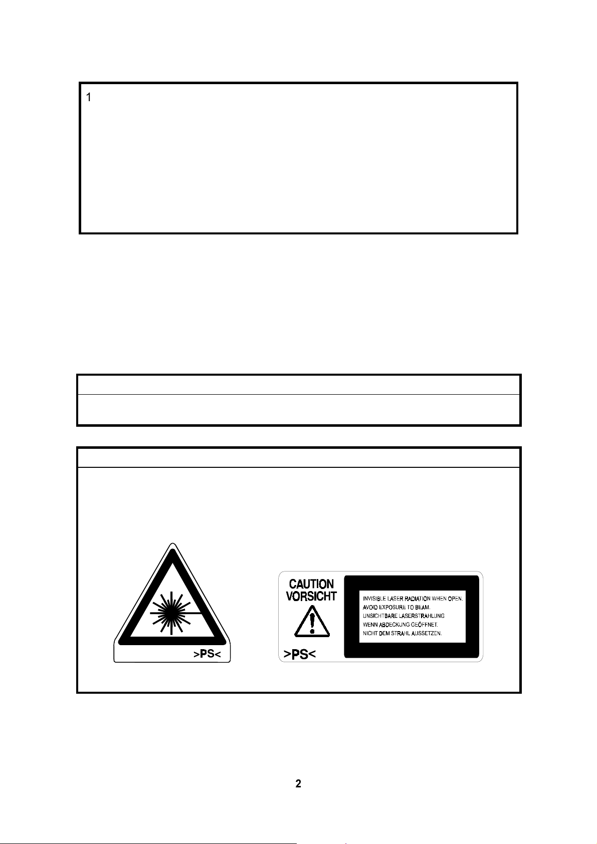
CAUTION MARKING:
2
Page 4

June 30, 1998 SPECIFICATIONS
1. OVERALL MACHINE INFORMATION
1.1 SPECIFICATIONS
1.1.1 COPIER ENGINE
Configuration: Console
Copy Process: Dry electrostatic transfer system
Originals: Sheet/Book
Original Size: Maximum A3/11" x 17"
Minimum B6, 5½”x 8 ½” (using ADF)
Original Alignment: Rear left corner
Copy Paper Size: Maximum
A3/11" x 17" (1st/2nd Tray, By-pass)
B4/8 ½” x 14” (3rd Tray)
Minimum
B5/8 ½” x 11” lengthwise (1st Paper Tray)
A5/5
B5/8 ½” x 11” (3rd Paper Tray)
A6/5
Tandem Paper Tray (1st Tray)
A4/B5/8 ½” x 11” sideways only
1/2
1/2
" x 8
" x 8
" sideways (2nd Tray)
1/2
" lengthwise (By-pass)
1/2
Overall
Information
Duplex Copying: Maximum A3/11" x 17"
Minimum A5/5
1/2
" x 8
" lengthwise
1/2
Copy Paper Weight: Paper tray: 52.3 ~ 127.9 g/m2, 14 ~ 34 lb
Bypass feed table: 52.3 ~ 163 g/m2, 17 ~ 43 lb
Duplex copying: 64 ~ 104.7 g/m2, 17 ~ 28 lb
Reproduction Ratios: 6 reduction and 5 enlargement
Metric Version Inch Version
Enlargement 400%
200%
141%
122%
115%
Full Size 100% 100%
Reduction 93%
82%
75%
71%
65%
50%
400%
200%
155%
129%
121%
93%
85%
78%
73%
65%
50%
1-1
Page 5

SPECIFICATIONS June 30, 1998
Zoom: 32 ~ 400%
Copy Speed: Max. 65 cpm (A4 / 8 ½” x 11” sideways)
Resolution: Scanning: 400 dpi
Printing: 400 dpi
600 dpi (Printer Mode Only)
Gradation: 256 levels
Warm-up Time: Less than 330 s (from Off-mode)
Less than 30 s (from Low Power Mode)
First Copy Time:
(1st Tray)
Less than 3.7 s (Face up mode)
Less than 5.5 s (Face down mode)
Copy Number Input: Ten-key pad, 1 to 999
Copy Paper Capacity: Tray 1: 1000 sheets(when used as a tandem tray)
Tray 2: 550 sheets
Tray 3 (LCT): 1500 sheets
By-pass Tray: 50 sheets
Copy Tray Capacity:
(Output Tray)
A4/8 ½” x 11” : 500 sheets (100 µm thickness paper)
A3/11" x 17" : 250 sheets
Memory Capacity: RAM: 12MB
HDD: 1.7GB
Toner Replenishment: Cartridge exchange (1220g/ cartridge)
Toner Yield: 40k copies
(A4 sideways, 6% full black, 1 to 3 copying, including
toner recycling ratio 20%)
Power Source: North America:
120V, 60Hz, 20A
Europe/Asia:
220 ~ 240 V, 50Hz/60Hz, 10A
1-2
Page 6

June 30, 1998 SPECIFICATIONS
Power Consumption: A229 copier (120 V Model)
Copier only Full system*
Warm-up About 1.290 kW About 1.310 kW
Stand-by About 0.235 kW About 0.255 kW
Copying About 1.560 kW About 1.650 kW
Maximum Less than 1.75 kW Less than 1.75 kW
Energy Saver About 0.210 kW About 0.230 kW
Low Power About 0.205 kW About 0.225 kW
Off Mode About 0.017 kW About 0.017 kW
A229 copier (220 to 240 V Model)
Copier only Full system*
Warm-up About 1.250 kW About 1.270 kW
Stand-by About 0.245 kW About 0.260 kW
Copying About 1.500 kW About 1.600 kW
Maximum Less than 1.75 kW Less than 1.75 kW
Energy Saver About 0.220 kW About 0.235 kW
Low Power About 0.215 kW About 0.230 kW
Off Model About 0.017 kW About 0.017 kW
Overall
Information
Noise Emission:
Sound Power Level:
Stand-by Less than 50 dB(A) Less than 50 dB(A)
Copying (ADF 1 to 1) Less than 72 dB(A) Less than 72 dB(A)
Copying (From Memory) Less than 71 dB(A) Less than 71 dB(A)
Sound Pressure Level:
Stand-by Less than 40 dB(A) Less than 40 dB(A)
Copying (ADF 1 to 1) Less than 60 dB(A) Less than 61 dB(A)
*Full System:
Mainframe with LCT and Finisher
The measurements were made in accordance with ISO 7779 at
the operator position.
Copier only Full system
The measurements were made in accordance with ISO 7779.
Copier only Full system
Copying (From Memory) Less than 59 dB(A) Less than 59 dB(A)
1-3
Page 7

SPECIFICATIONS June 30, 1998
Dimensions:
(W x D x H)
Weight: 188 kg (without options)
Optional Equipment:
690 x 750 x 1138 mm (27.2” x 29.5” x 44.8”)
(without ADF right exit tray, and options)
• Output tray (A814-01)
• Finisher (A697)
• Large capacity tray (A698)
• Punch unit (A812)
1.1.2 ADF
Original Size: Normal Original Mode:
A3 to B6, DLT to HLT
Thin Original Mode:
A3 to B6 sideways, DLT to HLT
Duplex Original Mode:
A3 to B5, DLT to HLT
Original Weight: Normal Original Mode: 52 ~ 128 g/m2, 14 ~ 34 lb
Thin Original Mode: 40 ~ 128 g/m2, 11 ~ 34 lb
Duplex Original Mode: 52 ~ 105 g/m2, 14 ~ 28 lb
Table Capacity: 100 sheets (80 g/m2, 20 lb)
Original Standard Position: Rear left corner
Separation: FRR
Original Transport: One flat belt
Original Feed Order: From the top original
Power Source: DC 24V from the copier
Power Consumption: 70 W
Dimensions (W x D x H): 680 x 529.5 x 150 mm
1-4
Page 8
June 30, 1998 MACHINE CONFIGURATION
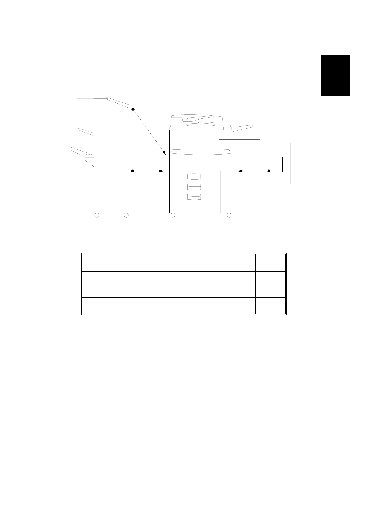
1.2 MACHINE CONFIGURATION
2
34
1
Overall
Information
Item Machine Code No.
Mainframe A229 3
Output Tray A814 - 01 2
Finisher A697 1
Large Capacity Tray A698 4
Punch Unit (Option for Finisher)
A812-17 (3 holes)
A812-27 (2 holes)
A229V501.WMF
1-5
Page 9
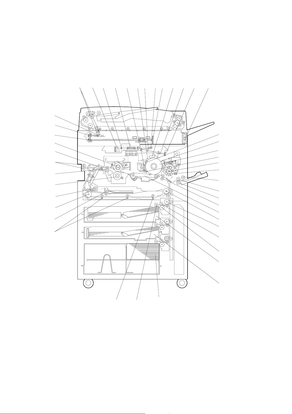
MECHANICAL COMPONENT LAYOUT June 30, 1998
1.3 MECHANICAL COMPONENT LAYOUT
1.3.1 COPIER ENGINE
45
44
43
42
41
40
39
38
3
2
1
37
8
41014 15
7
65
9
13
1211
16
17
18
19
20
21
22
23
24
25
26
27
28
29
30
1-6
31
32
33
A229V507.WMF
343536
Page 10

June 30, 1998 MECHANICAL COMPONENT LAYOUT
1. 3rd Mirror
2. 2nd Mirror
3. 1st Mirror
4. Exposure Lamps
5. LD Unit
6. Cylindrical Lens
7. Polygonal Mirror
8. Cleaning Brush
9. Quenching Lamp
10. Barrel Toroidal Lends (BTL)
11. F-theta Mirror
12. SBU
13. Charge Corona Unit
14. Shield Glass
15. Laser Synchronization Detector
16. Optics Cooling Fan Motor
31. Separation Roller
32. Tray 1 (Tandem Tray)
33. Tray 2 (550-sheet Tray)
34. Tray 3 (1500-sheet lage capacity
tray)
35. Pick-up Roller
36. Duplex Feed Roller
37. Duplex Transport Rollers
38. Reverse Trigger Roller
39. Inverter Unit Paper Exit Roller
40. Inverter Feed Roller
41. Pressure Roller
42. Transport Rollers
43. Paper Exit Rollers
44. Curl Correction Roller
45. Hot Roller
Overall
Information
17. Drum Cleaning Blade
18. Drum Potential Sensor
19. Drum
20. Pick-off Pawl
21. Development Unit
22. TD Sensor
23. Pick-up Roller
24. Feed Roller (By-pass Tray)
25. Separation Roller
26. Registration Rollers
27. Transfer Belt Unit
28. Relay Roller
29. Vertical Transport Rollers
30. Feed Roller
1-7
Page 11

MECHANICAL COMPONENT LAYOUT June 30, 1998
1.3.2 ADF
21
20
19
1
2
A229V506.WMF
18
3
17
1. Separation Roller
2. Feed Belt
3. Pick-up Roller
4. Bottom Plate
5. Original Tray
6. Upper Tray Exit Roller
4
5
6
7
8
9
10
11
16
15
14
13
12
12. Exit Gate
13. Inverter Roller
14. Exit Sensor
15. Upper Exit Tray
16. Transport Belt
17. Registration Sensor
7. Inverter Gate
8. Inverter Guide Roller
9. Inverter Sensor
10. Right Tray Exit Roller
11. Right Exit Tray
18. Lower Transport Roller
19. Width Sensor
20. Upper Transport Roller
21. Entrance Sensor
1-8
Page 12
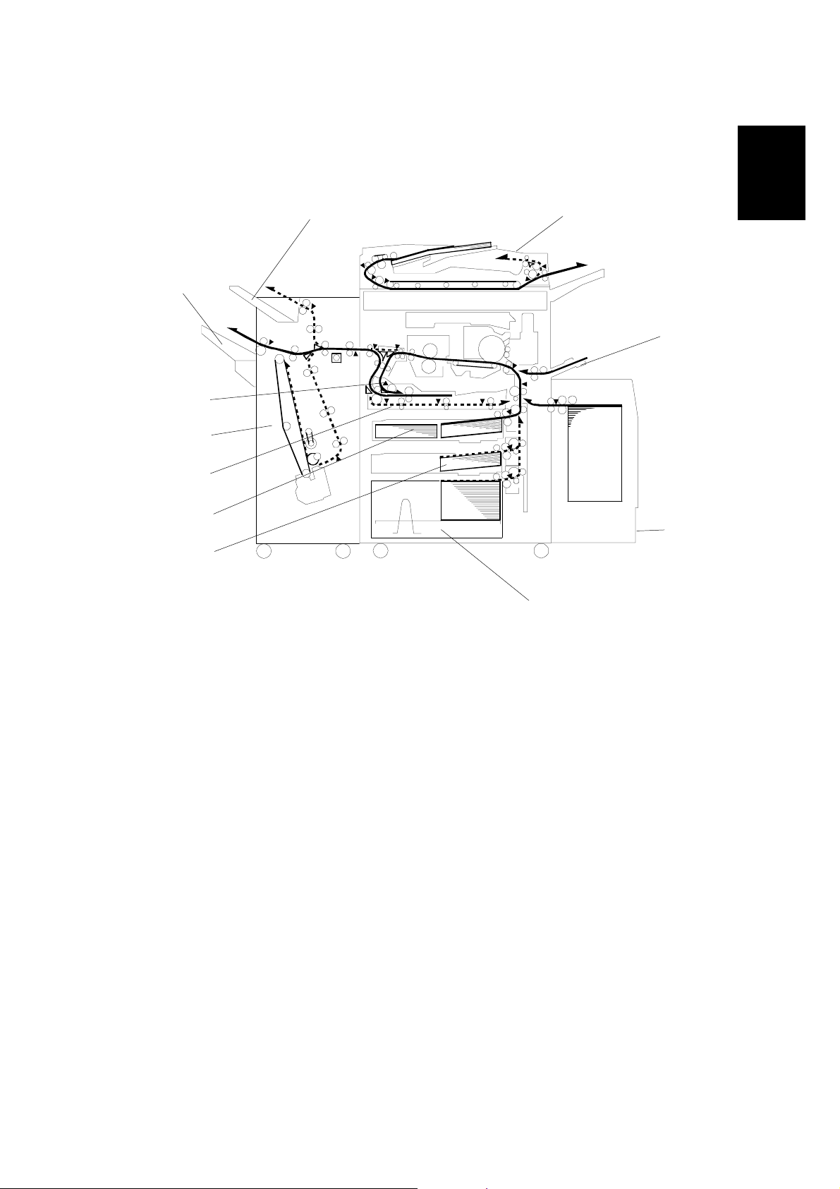
June 30, 1998 PAPER PATH
1.4 PAPER PATH
11
10
9
8
7
1
2
Overall
Information
6
5
1. ADF
2. By-pass Tray
3. Optional LCT
4. Tray 3 (1500-sheet LCT)
5. Tray 2 (550-sheet Tray)
6. Tray 1 (Tandem Tray)
3
A229V504.WMF
4
7. Duplex Unit
8. Finisher
9. Inverter Unit
10. Shift Tray
11. Upper Tray
1-9
Page 13
COPY PROCESS June 30, 1998
1.5 COPY PROCESS
1
A229V508.WMF
2
3
10
4
9
5
8
7
6
A229V510.WMF
1. EXPOSURE
Two xenon lamps expose the original. Light reflected from the original passes to
the CCD, where it is converted into an analog data signal. This data is converted to
a digital signal, processed, and stored in the memory. At the time of printing ,the
data is retrieved and sent to the laser diode. For multi-copy runs, the original is
scanned once only and stored to the hard disk.
2. DRUM CHARGE
An OPC (organic photoconductor) drum is used in this machine. In the dark, the
charge corona unit gives a negative charge to the drum. The grid plate ensures
that corona charge is applied uniformly. The charge remains on the surface of the
drum because the OPC layer has a high electrical resistance in the dark.
3. LASER EXPOSURE
The processed data from the scanned original is retrieved from the hard disk and
transferred to the drum by two laser beams, which form an electrostatic latent
image on the drum surface. The amount of charge remaining as a latent image on
the drum depends on the laser beam intensity, which is controlled by the SBICU
board.
1-10
Page 14

June 30, 1998 COPY PROCESS
4. DRUM POTENTIAL SENSOR
The drum potential sensor detects the electric potential on the drum to correct
various process control elements.
5. DEVELOPMENT
The magnetic developer br ush on the development rollers comes in contac t w i th
the latent image on the drum surface. Toner particles are electrostatically attracted
to the areas of the drum surface where the laser reduced the negative charge on
the drum.
6. IMAGE TRANSFER
Paper is fed to the area between the drum surface and the transfer belt at the
proper time to align the copy paper and the developed image on the drum. Then,
the transfer bias roller applies a high positive charge to the reverse side of the
paper through the transfer belt. This positive charge pulls the toner particles from
the drum to the paper. At the same time, the paper is electrically attracted to the
transfer belt.
7. PAPER SEPARATION
Overall
Information
Paper separates from the drum as a result of the electrical attraction between the
paper and the transfer belt. The pick-off pawls also help separate the paper from
the drum.
8. ID SENSOR
The laser forms a sensor pattern on the drum surface. The ID sensor measures the
reflectivity of the pattern. The output signal is one of the factors used for toner
supply control.
9. CLEANING
The cleaning brush removes toner remaining on the drum after image transfer and
the cleaning blade scrapes off all remaining toner.
10. QUENCHING
The light from the quenching lamp electrically neutralizes the charge on the drum
surface.
1-11
Page 15
DRIVE LAYOUT June 30, 1998
1.6 DRIVE LAYOUT
1.6.1 COPIER ENGINE
1
11
10
'
(
)
2
"
!
9
#$
8
7
6
&
&
3
%
&
4
1. Drum Motor
2. Scanner Motor
3. Fusing/Duplex Motor
4. Toner Recycling Clutch
5. Paper Feed Motor
6. Toner Collection Motor
7. Registration Motor
8. Relay Clutch
9. By-pass Feed Motor
10. By-pass Feed Clutch
11. Development Motor
1-12
5
!
Cleaning Unit
"
Scanner Unit
#
Transfer Belt Unit
$
Fusing Unit
%
Duplex Unit
&
Paper Feed Units
'
Toner Hopper
(
Development Unit
)
Drum
A229V505.WMF
Page 16
June 30, 1998 DRIVE LAYOUT
1.6.2 ADF
10
11
12
13
1
2
3
4
5
Overall
Information
6
9
8
7
C229V511.WMF
1. Pick-up Motor
2. Bottom Plate Motor
3. Feed-in Motor
4. Transport Motor
5. Upper Exit Roller
6. Feed-out Motor
7. Right Exit Roller
8. Transport Belt
9. Lower Transport Roller
10. Upper Exit Roller
11. Separation Roller
12. Feed Belt
13. Pick-up Roller
1-13
Page 17

ELECTRICAL COMPONENT DESCRIPTION June 30, 1998
1.7 ELECTRICAL COMPONENT DESCRIPTION
Refer to the electrical component layout on the reverse side of the point-to-point
diagram for the location of the components using the symbols and index numbers.
1.7.1 COPIER ENGINE
Symbol Name Function
Motors
M1 Scanner Drives the 1st and 2nd. 17
M2 Polygonal Mirror Turns the polygonal mirror. 25
M3 LD Positioning
M4 Drum Drives the drum and cleaning unit. 39
M5 Development Drives the development unit. 40
M6 Toner Supply Rotates the toner bottle to supply
M7
M8 Fusing/Duplex Drives the fusing unit, duplex unit,
M9 Toner Collection Transports the collected toner to the
M10 Toner Recycling
M11 Paper Feed Drives all feed and transport rollers in
M12 1st Tray Lift Raises and lowers the bottom plate in
M13 2nd Tray Lift Raises the bottom plate in the 2nd
M14
M15 By-pass Feed Drives the by-pass feed rollers. 43
M16 Registration Drives the registration rollers. 42
M17 Rear Fence Drive Moves the paper stack in the left
M18 Side Fence Drive Opens and closes the front and rear
M19 Jogger
M20 Optics Cooling Fan Removes heat from the optics unit. 24
M21
M22 Exhaust Fan Removes heat from around the fusing
Charge Corona Wire
Cleaner
3rd Tray Lift Raises and lowers the bottom plate in
Polygonal Mirror
Motor Cooling Fan
Rotates the LD unit to adjust the LD
beam pitch when a different resolution
is selected.
toner to the development unit.
Drives the charge corona wire
cleaner.
inverter unit, and paper exit rollers.
toner collection bottle.
Drives the air pump to send recycled
toner to the development unit.
the paper tray unit.
the 1st paper tray.
paper tray.
the 3rd paper tray.
tandem tray to the right tandem tray.
side fences of the tandem tray.
Drives the jogger fences to square the
paper stack in the duplex unit.
Removes heat from around the
polygonal mirror motor.
unit.
Index
No.
29
48
90
37
5
8
46
44
45
135
72
77
80
49
38
1-14
Page 18

June 30, 1998 ELECTRICAL COMPONENT DESCRIPTION
Symbol Name Function
M23 Fusing Fan Removes heat from around the fusing
unit.
M24 Duplex Cooling Fan Removes heat from around the duplex
unit.
M25 PSU Cooling Fan Removes heat from around the PSU. 5 9
Magnetic Clutches
MC1 Toner Supply Turns the toner supply roller to supply
toner to the development unit.
MC2 Toner Recycling Drives the t oner recycling unit. 2
MC3 1st Paper Feed Starts paper feed from tray 1. 112
MC4 2nd Paper Feed Starts paper feed from tray 2. 115
MC5 3rd Paper Feed Starts paper feed from tray 3. 12
MC6 By-pass Feed Starts paper feed from the by-pass
table.
MC7 Duplex Transport
Drives the duplex transport rollers to
transport the paper to the duplex feed
rollers.
MC8 Duplex Feed Starts paper feed out of the duplex
tray back into the machine via to the
relay rollers.
MC9 1st Vertical Relay Dr ives the 1st vertical tr ansport
rollers.
MC10 2nd Vertical Relay Drives the 2nd vertical transport
rollers.
MC11 3rd Vertical Relay
Drives the 3rd vertical transport
rollers.
MC12 Relay Drives the relay rollers. 103
Index
No.
50
47
41
100
67
70
113
116
119
Overall
Information
Switches
SW1 Main Power
SW2 Operation
SW3 Front Door Safety
Switch 1
SW4
Front Door Safety
Switch 2
SW5 Front Door Safety
Switch 3
SW6 Lower Front Door
Safety
SW7 Toner Collection
Bottle Set
SW8 Toner Overflow
Provides power to the machine. If this
11
is off, there is no power supplied to
the machine.
Provides power for machine
30
operation. The machine still has
power if this switch is off.
Cuts the +5 V LD dc power line. 12
Detects if the front door is open or not,
13
and cuts the +24 V dc power line.
Cuts the +5 V LD dc power line. 14
Cuts the +24 V dc power line. 10
Detects if the toner collection bottle is
7
set or not.
Detects when the toner collection
6
bottle is full.
1-15
Page 19

ELECTRICAL COMPONENT DESCRIPTION June 30, 1998
Symbol Name Function
SW9 Paper Size Determines the size of paper in tray 2. 3
SW10 3rd Tray Down Lowers the tray 3 (LCT) bottom plate 136
SW11 By-pass Tray Detects if the by-pass tray is open or
closed.
Solenoids
SOL1 Transfer Belt Lift Controls the up-down movement of
the transfer belt unit.
SOL2 1st Pick-up Controls the up-down movement of
the pick-up roller in tray 1.
SOL3 2nd Pick-up
Controls the up-down movement of
the pick-up roller in tray 2.
SOL4 3rd Pick-up Controls the up-down movement of
the pick-up roller in tray 3.
SOL5 By-pass Pick-up Controls the up-down movement of
the pick-up roller for by-pass feed.
SOL6 1st Separation Roller
Controls the up-down movement of
the separation roller in tray 1.
SOL7 2nd Separation Roller Controls the up-down movement of
the separation roller in tray 2.
SOL8 3rd Separation Roller Controls the up-down movement of
the separation roller in tray 3.
SOL9 Tandem Lock
Releases the left tandem feed tray so
that it can be separated from the right
tandem feed tray.
SOL10 Duplex Inverter Gate Moves the junction gate to direct
copies to the duplex tray or to the
paper exit.
SOL11 Reverse Roller Controls the up-down movement of
the reverse trigger roller.
SOL12 Guide Plate Opens the guide plate when a paper
misfeed occurs around this area.
SOL13 Inverter Gate
Opens the inverter gate during a
duplex job.
Index
No.
97
92
111
117
121
98
114
118
122
4
82
81
102
96
Sensors
S1 Scanner HP
Informs the CPU when the 1st and
2nd scanners are at home position.
S2 Original Width Detects original width. This is one of
APS (Auto Page Select) sensors.
S3 Original Length 1 Detects original length. This is one of
APS (Auto Page Select) sensors.
S4 Original Length 2
Detects original length. This is one of
APS (Auto Page Select) sensors.
S5 LD Unit Home
Position
Informs the CPU when the LD unit is
at home position.
S6 Drum Potential Detects the drum surface potential. 88
1-16
35
36
18
20
28
Page 20

June 30, 1998 ELECTRICAL COMPONENT DESCRIPTION
Symbol Name Function
S7 Toner Density (TD) Detects the amount of toner in the
developer.
S8 Image Density (ID) Detects the density of the ID sensor
pattern on the drum.
S9 Toner End Detects toner end. 94
S10
Toner Collection
Monitors the toner collection motor. 9
Motor
S11 Toner Recycling Monitors the toner recycling and
collection unit operation.
S12 1st Paper Feed Controls the 1st paper feed clutch
off/on timing and the 1st pick-up
solenoid off timing.
S13 2nd Paper Feed Contr ols the 2nd paper feed clutch
off/on timing and the 2nd pick-up
solenoid off timing.
S14 3rd Paper Feed
Controls the 3rd paper feed clutch
off/on timing and the 3rd pick-up
solenoid off timing.
S15 1st Tray Lift Detects when the paper in tray 1 is at
the correct height for paper feed.
S16 2nd Tray Lift
Detects when the paper in tray 2 is at
the correct height for paper feed.
S17 3rd Tray Lift Detects when the paper in tray 3 is at
the correct height for paper feed.
S18 1st Paper End Informs the CPU when tray 1 runs out
of paper.
S19 2nd Paper End
Informs the CPU when tray 2 runs out
of paper.
S20 3rd Paper End Informs the CPU when tray 3 runs out
of paper.
S21 By-pass Paper End Informs the CPU that there is no
paper in the by-pass feed table.
S22 1st Paper Near End
Informs the CPU when the paper in
tray 1 is almost finished.
S23 2nd Paper Near End Informs the CPU when the paper in
tray 2 is almost finished.
S24 3rd Paper Near End Inf orm s the CPU when the paper in
tray 3 is almost finished.
S25
Rear Fence HP Informs the CPU when the tandem
tray rear fence is in the home position.
S26 Rear Fence Return Informs the CPU when the tandem
tray rear fence is in the return
position.
S27
Side Fence Close Detects whether the tandem tray side
fence is closed or not.
S28 Side Fence
Positioning
Informs the CPU when the tandem
tray side fences are open.
Index
No.
95
91
1
129
126
125
132
128
123
130
127
124
99
110
131
133
79
78
75
74
Overall
Information
1-17
Page 21

ELECTRICAL COMPONENT DESCRIPTION June 30, 1998
Symbol Name Function
S29 Base Plate Down Detects when the bottom plate is
completely lowered to stop the 1st
tray lift motor.
S30
Left Tandem Paper
End
Informs the CPU when the left tandem
tray runs out of paper.
S31 3rd Tray Paper Detects whether there is paper or not
in tray 3.
S32 Tray Down Sensor Informs the CPU when the bottom
plate is completely lowered, to stop
the 3rd tray lift motor.
S33 Duplex Entrance
Sensor
Detects the leading and trailing edges
of the paper to determine the reverse
roller solenoid on or off timing.
S34 Duplex Transport
Sensor 1
S35 Duplex Transport
Sensor 2
S36 Duplex Transport
Sensor 3
S37 Duplex Jogger HP
Detects the position of paper in the
duplex unit.
Detects the position of paper in the
duplex unit.
Detects the position of paper in the
duplex unit.
Detects if the duplex jogger fences
are at the home position or not.
S38 Relay Detects misfeeds. 104
S39 Registration Detects misfeeds and controls
registration clutch off-on timing.
S40 Guide Plate Position Detects whether the registration guide
plate is closed or not.
S41 Fusing Exit Detects misfeeds. 107
S42 Exit Detects misfeeds. 108
S43 Tray Paper Limit Detects paper overflow on the output
tray.
Index
No.
76
73
135
134
65
66
68
71
69
106
105
109
PCBs
PCB1 SBICU
Controls all base engine functions
both directly and through other control
boards.
PCB2 PSU Provides dc power to the system and
ac power to the fusing lamp and
heaters.
PCB3 IOB Controls the mechanical parts of the
machine (excluding the scanner unit
section), and the fusing lamp.
PCB4 SBU
Contains the CCD, and outputs a
video signal to the SBICU board.
PCB5 Scanner Motor Drive Drives the scanner motor. 51
PCB6 Lamp Regu lat or Provides dc power to the exposure
lamp.
PCB7 DC/ DC Convert er Generates dc voltages. 19
PCB8 LDDR Controls the laser diodes. 27
1-18
23
57
52
21
22
Page 22

June 30, 1998 ELECTRICAL COMPONENT DESCRIPTION
Symbol Name Function
PCB9 Int erf ace Passes signals and dc supplies from
the PSU and IOB to motors and other
components.
PCB10
Paper Feed Control
Board (PFB)
Controls the mechanical parts of all
paper feed sections.
PCB11 Operation Panel 1 Controls the components on the right-
hand side of the operation panel.
PCB12 Operation Panel 2 Controls the components on the left-
hand side of the operation panel.
PCB13 LCD Control Cont rols the LCD. 33
PCB14 By-pass Paper Size
Detects the paper width on the by-
pass tray.
PCB15 Mother (Option) Connects the printer control board. 54
PCB16 Printer Control
Receives print data from a PC. 55
(Option)
Lamps
L1 Exposure Lamps Apply high intensity light to the original
for exposure.
L2 Fusing Lamp 1 Provides heat to the hot roller. 86
L3 Fusing Lamp 2 Provides heat to the hot roller. 85
L4 Quenching Neutralizes any charge remaining on
the drum surface after cleaning.
Index
No.
64
Overall
Information
58
31
34
101
15
89
Power Packs
PP1 Charge Provides high voltage for the charge
corona wires and the grid plate.
PP2 Development
Provides high voltage for the
development unit.
PP3 Transfer Provides high voltage for the transfer
belt.
Others
TF1 Fusing Thermofuse Opens the fusing lamp circuit if the
fusing unit overheats.
TH1 Fusing Thermistor Detects the temperature of the hot
roller.
H1
Optics AntiCondensation
Turns on when the main switch is off
to prevent moisture from forming on
the optics.
H2 Drum Turns on when the main switch is off
to prevent moisture from forming
around the drum.
H3 Tr ay Heater 1 Turns on when the main switch is off
to keep paper dry in the paper tray.
H4 Tr ay Heater 2 Turns on when the main switch is off
to keep paper dry in the paper tray.
87
56
93
84
83
16
63
62
60
1-19
Page 23

ELECTRICAL COMPONENT DESCRIPTION June 30, 1998
Symbol Name Function
CB1 Circuit Breaker Provides back-up high current
protection for the electrical
components.
HDD 1 HDD
LCD 1 LCD Displays the operation menus and
LSD 1 Laser Synchronization
Detector
TP1 Touch Panel Monitors the key matrix. (32)
Scanned image data is compressed
and held here temporarily.
messages.
Detects the laser beam at the start of
the main scan.
Index
No.
61
53
32
26
1-20
Page 24

June 30, 1998 ELECTRICAL COMPONENT DESCRIPTION
1.7.2 ADF
Symbol Name Function Index No.
Motors
M1 Pick-up Moves the pick-up roller up and down. 2
M2
Feed-in
M3 Transport Drives the transport belt. 7
M4 Feed-out Drives the exit and invert er rollers . 11
M5 Bottom plate Moves the bottom plate up and down. 5
Sensors
APS Start Informs the CPU when the DF is opened and
S1
S2 DF Position Detects whether the DF is lifted or not. 10
S3 Original Set Detects whether an original is on the table. 23
S4
S5
S6
Bottom Plate HP Detects whether the bottom plate is in the
Bottom Plate
Position
Pick-up Roller
HP
Entrance Detects when to restart the pick-up motor to
S7
Registration Detect s the leading edge of the original to
S8
S9 Original Width 1 Detects the original width. 21
S10 Original Width 2 Detects the original width. 20
S11 Original Width 3 Detects the original width. 19
S12
Exit
Inverter Detects when to turn the inverter gate and
S13
S14
S15
Feed Cover
Exit Cover Detects whether the exit cover is open or
Solenoids
SOL1 Exit Gate Opens and closes the exit gate. 13
SOL2 Inverter Gate Opens and closes the inverter gate. 16
Drives the feed belt, and the separation,
pick-up, and transport rollers.
closed (for platen mode) so that the original
size sensors in the copier can check the
original size.
down position or not.
Detects when the original is at the correct
position for feeding.
Detects whether the pick-up roller is up or
not.
lift up the pick-up roller, detects when to
change the feed motor direction, detects the
trailing edge of the original to finish checking
the original length, and checks for misfeeds.
check the original length, detects when to
stop the original on the exposure glass, and
checks for misfeeds.
Detects when to stop the transport belt
motor and checks for misfeeds.
exit gate solenoids off and checks for
misfeeds.
Detects whether the feed cover is open or
not.
not.
6
9
17
24
1
22
18
15
14
3
12
Overall
Information
1-21
Page 25

ELECTRICAL COMPONENT DESCRIPTION June 30, 1998
Symbol Name Function Index No.
PCBs
PCB1
PCB2
DF Main
DF Indicator Indicates whether an original has been
Controls the DF and communicates with the
main copier boards.
placed in the feeder; and indicates whether
SADF mode has been selected.
8
4
1-22
Page 26
June 30, 1998 DOCUMENT FEEDER
2. DETAILED DESCRIPTIONS
2.1 DOCUMENT FEEDER
2.1.1 PICK-UP ROLLER RELEASE MECHANISM
[F]
[D]
[C]
[B]
[E]
Detailed
Descriptions
[A]
A229D651.WMF
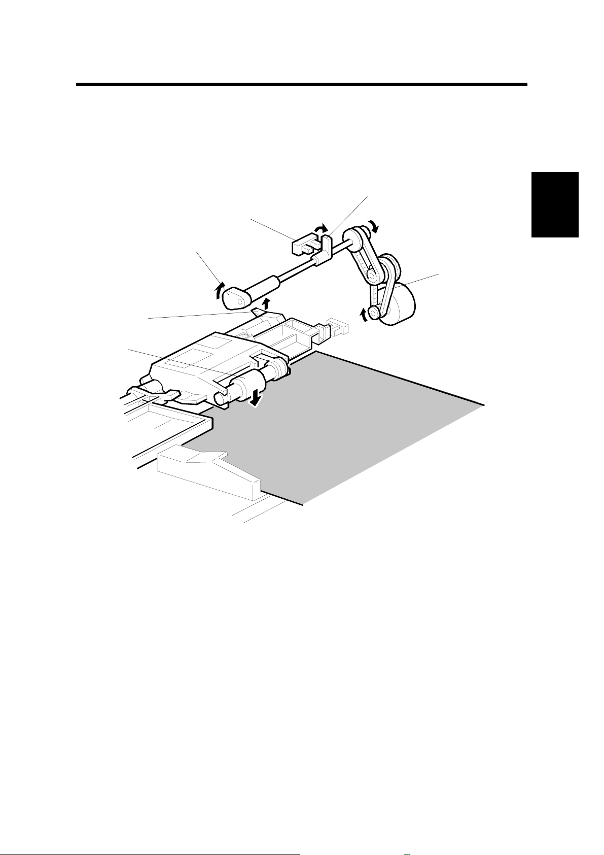
When the original set sensor is off (no original on the original tray), the pick-up
roller stays in the up position.
When the original set sensor turns on (or when the trailing edge of a page passes
the entrance sensor while pages remain on the original tray), the pick-up motor [A]
turns on. The cam [B] rotates away from the pick-up roller release lever [C]. The
lever then rises and the pick-up roller [D] drops onto the original.
When the original reaches the entrance sensor, the pick-up motor turns on again.
The cam pushes the lever down, and the pick-up roller rises until the pick-up roller
HP sensor [E] detects the actuator [F].
2-1
Page 27
DOCUMENT FEEDER June 30, 1998
2.1.2 BOTTOM PLATE LIFT MECHANISM
[F]
[B]
[A]
[F]
[E]
[C]
[D]
A229D652.WMF
When an original is placed on the original tr ay, the origin al set sensor [A] turns on ,
the pick-up roller [B] drops on to the original, and the bottom plate position sensor
[C] turns off. Then the bottom plate motor [D] turns on and lifts the bottom plate [E]
by raising the lift lever [F] until the bottom plate position sensor turns on.
When the bottom plate po sition sensor turns off du r ing original feed, the bottom
plate motor turns on and lifts the bottom plate until the bottom plate position sensor
turns on. This keeps the original at the correct height for feeding.
2-2
Page 28
June 30, 1998 DOCUMENT FEEDER
2.1.3 PICK-UP AND SEPARATION MECHANISM
[D]
[A]
[B]
[C]
A806D105.WMF
[B]
[A]
Detailed
Descriptions
[C]
A806D106.WMF
The original separation system is an FRR system. The pick-up roller [A], feed belt
[B], and separation roller [C] are driven by the feed-in motor [D].
To drive this mechanism, the feed-in motor turns in the forward direction.
When two sheets of the original are fed by the pick-up roller, the separation roller
turns in the opposite direction to the feed belt and the 2nd sheet is pushed back to
the original tray. When there is only one sheet between the feed belt and
separation roller, the separation roller rotates in the same direction as the feed belt.
This is because the separation roller contains a torque limiter.
2-3
Page 29
DOCUMENT FEEDER June 30, 1998
2.1.4 ORIGINAL FEED MECHANISM
[B]
[D]
[A]
[C]
A806D107.WMF
When the leading edge of the original turns the entrance sensor [A] on, the feed - in
motor [B] changes direction, and turns in reverse. However, the transport rollers [C]
keep turning in the same direction because of a combination of one-way clutches
(see the next page).
At the same time, the pick-up motor starts again and the pick-up roller [D] is lifted
up. When the pick-up roller HP sensor turns on, the pick-up motor stops (see Pickup Roller Release Mechanism).
2-4
Page 30
June 30, 1998 DOCUMENT FEEDER
r
[L]
2.1.5 ORIGINAL FEED DRIVE MECHANISM
[M]
[K]
[E]
[F]
[G]
[J]
Feed Start
[H]
[E]
[C]
[B]
A806D500.WMF
[I]
[D]
[A]
[F]
[G]
[H]
[K]
Detailed
Descriptions
[D]
Feed
No Rotation
[M]
[L]
[J]
[I]
[A]
A806D501.WMF
The separation roller [A] and transport rollers [B] always turn in the same direction
because of a combination of gears and one-way clutches, even if the feed-in motor
[C] changes direction. However, the feed belt [D] stops during original feed.
The gears H, L, and M each have a one-way clutch.
Original Feed Start
When the feed-in motor turns on, the drive is tr ansferred as follows:
E→H→K→Feed Belt [D]
→
L
Separation Roller [A]
G
→
I→→J
Transport Roller
Original Feed
When the leading edge of the original turns on the entrance sensor, the feed-in
motor turns in reverse, and the drive is transferred as follows:
M→Separation Roller
E→F→G
→
J
Transport Rolle
→
→
I
2-5
Page 31

DOCUMENT FEEDER June 30, 1998
2.1.6 ORIGINAL SIZE DETECTION
[D]
[E]
[A]
[B]
[C]
A806D108.WMF
[A]
A4 Lengthwise
B4/B5 Sideways
DLT/LT Sideways
A3/A4 Sideways
[B]
[C]
A806D503.WMF
The DF detects original width using three original width sensors-1 [A], -2 [B], -3 [C],
and detects original length using entrance sensor [D] and registration sensor [E].
The CPU counts the feed-in motor pulses between when the leading edge of the
original turns on the registration sensor and when the trailing edge of the original
turns off the entrance sensor.
The machine detects the original size from the combination of readings from all
sensors.
2-6
Page 32

June 30, 1998 DOCUMENT FEEDER
2.1.7 ORIGINAL TRANSPORT MECHANISM
[B]
[C]
[A]
A806D109.WMF
[D]
Detailed
Descriptions
3.5 mm
[E]
A806D509.WMF
The transport belt [A] is driven by the transport belt motor [B]. The transport belt
motor starts when the copier sends an original feed-in signal.
Inside the transport belt are five pressure rollers which give the proper pressure
between the belt and original. The pressure roller [C] closest to the left original
scale is made of rubber for the stronger pressure needed for thick originals. The
other rollers are sponge rollers.
Since the copier's original position is at the left rear corner, the original [D] fed from
the DF must also be at this position. But if the original was to be fed along the rear
scale [E], original skew, jam, or wrinkling may occur.
To prevent such problems, the original transfer position is set to 3.5 mm away from
the rear scale as shown. The 3.5 mm gap is compensated for by changing the
starting position of the main scan.
2-7
Page 33

DOCUMENT FEEDER June 30, 1998
2.1.8 ORIGINAL SKEW CORRECTION MECHANISM
[A]
A680D510.WMF
The transport belt motor remains energized to carry the original approximately 7
mm past the left scale [A] (see the middle drawing). Then the motor stops and
reverses to feed the original back against the left scale (see the bottom drawing).
This forces the original to hit the left scale and this aligns the trailing edge to
minimize the original skew on the exposure glass.
If thin original mode is selected, the original is not forced back against the left
scale. This is to prevent any damage to the original.
After a two-sided original has been inverted to copy the 2nd side, it is fed in from
the inverter against the left scale (see the bottom drawing; the top two drawings do
not apply in this mode).
The amount of reverse feed against the left scale can be adjusted with SP modes.
2-8
Page 34

June 30, 1998 DOCUMENT FEEDER
2.1.9 ORIGINAL INVERSION AND FEED-OUT MECHANISM
General Operation
[A]
Detailed
Descriptions
A806D110.WMF
When the sca nner reaches the return position, the copier’s CPU sends the feed-out
signal to the DF. When the DF receives the feed-out signal, the transport belt motor
and feed-out motor [A] turn on. The original is then fed out to the exit tray or fed
back to the exposure glass after reversing in the inverter section.
This DF has two exit trays. For single-sided original mode, the original is fed out to
the right exit tray and for double-sided original mode, the original is fed out to the
upper exit tray.
This causes the originals to be fed out in the correct order on the exit trays and
allow the best one-to-one copy speed for each mode. The user can change the exit
tray to the upper exit tray for single-sided mode (for example, if there is not enough
space in the room for the right exit tray to be installed). However, one-to-one copy
speed for this mode is reduce d.
2-9
Page 35

DOCUMENT FEEDER June 30, 1998
Original Inversion Mechanism
[F]
[B]
[E]
[G]
[A]
A806D113.WMF
[C]
[D]
When the DF receives the original invert signal from the copier, the transpor t belt
motor, feed-out motor, exit gate solenoid [A], and inverter gate solenoid [B] turn on
and the original is fed back to the exposure glass through the inverter roller [C], exit
gate [D], inverter guide roller [E], inverter gate [F], and inverter roller.
The transport belt motor turns in reverse shortly after the leading edge of the
original turns on the inverter sensor [G], and feeds the original to the left scale.
2-10
Page 36

June 30, 1998 DOCUMENT FEEDER
Original Exit Mechanism (Single-Sided Original Mode)
[A]
Detailed
Descriptions
[B]
A806D111.WMF
The exit gate solenoid [A] remains off and the original is fed out to the right exit
tray. The transport belt motor turns off after the exit sensor [B] turns off.
To stack the originals neatly on the exit tray, the feed-out motor speed is reduced
approximately 30 mm before the trailing edge of the original turns off the exit
sensor.
2-11
Page 37

DOCUMENT FEEDER June 30, 1998
Original Exit Mechanism (Double-Sided Original Mode)
[B]
[D]
[A]
[C]
A806D112.WMF
The exit gate solenoid [A] turns on and the inverter gate solenoid [B] remains off,
and the original is fed out to the upper tray. The transport belt motor turns off when
the trailing edge of the original passes through the exit sensor [C].
To stack the originals neatly on the upper tray, the feed-out motor speed is
reduced shortly after the trailing edge of the original turns off the inverter sensor
[D].
2-12
Page 38

June 30, 1998 DOCUMENT FEEDER
2.1.10 JAM CONDITIONS
A
[M]
[I]
B
C
DE
G
[L]
H
Detailed
Descriptions
[J]
F
[K]
A806D502.WMF
1. The entrance sensor [I] has still not turned on when the feed-in motor has fed
the original twice the length [A] (between the original set position and the
entrance sensor).
2. The registration sensor [J] has still not turned on when the feed-in motor has
fed the original the length [B] (between the pre-feed position and the entrance
sensor).
3. The entrance sensor has still not turned off when the feed-in motor has fed the
original 1062 mm.
4. The registration sensor has still not turned off when the feed-in motor has fed
the original twice the length [C] (between the entrance sensor and the
registration sensor).
5. The exit sensor [K] has still not turned on when the transport and feed-out
motors have fed the original the distance [N].
N = F + 600 mm – (D + E)
F: Length between the original scale and the exit sensor
D+E : Total length of the originals on the exposure glass (e.g., for two A4
sideways pages. If there is only one page on the glass, E is zero)
6. The exit sensor has still not turned off when feed-out motor has fed the original
the length [G] (between the exit roller [L] and the exit sensor) + 65 mm after
reducing the feed-out speed.
7. The inverter sensor [M] is still not on when the feed-out motor has fed the
original twice the length [H] (between the exit sensor and the inverter sensor).
8. The exit sensor has still not turned off when the feed-out motor has fed the
original the length of the original after the inverter sensor [M] turned on.
9. The inverter sensor has still not turned off when the feed-out motor has fed the
original twice the length [H] (between the exit sensor and the inverter sensor)
after the exit sensor turned off.
2-13
Page 39

DOCUMENT FEEDER June 30, 1998
2.1.11 TIMING CHARTS
A4 Sideways: One-Sided Original (Three Pages)
: Original is set
: Feed in/out command
: Original size detected
: Original stops
: Pre-feed completed
: Feed-out completed
: Feed-out command
➀
➁
➂
➃
➄
: No originals remain
➅
➆
➇
Time [s]
➆
➆
➁
➁
➁
➅
➅
➃➅
➂➄➃➇
➂➃➄
➀
01234567
TXD/RXD
Original Set Sensor
Bottom Plate Position Sensor
Pick-up Roller HP Sensor
Bottom Plate HP Sensor
Pick-up Motor
Bottom Plate Motor
Entrance Sensor
Registration Sensor
Exit Sensor
Inverter Sensor
2-14
Feed-in Motor
Transport Motor
Feed-out Motor
A806D504.WMF
Inverter Gate Solenoid
Exit Gate Solenoid
Page 40

June 30, 1998 DOCUMENT FEEDER
A3: Two-Sided Original (One Page)
Time [s]
Feed-out
Completed
Feed-out Command
Invert Command
0123456
Stops
Original
Original Set
1st
Detailed
Descriptions
Side
TXD/RXD
Original Set Sensor
Bottom Plate Position Sensor
Pick-up Roller HP Sensor
Bottom Plate HP Sensor
Pick-up Motor
Bottom Plate Motor
Entrance Sensor
Registration Sensor
2-15
Inverter Sensor
Exit Sensor
Feed-in Motor
Transport Motor
Feed-out Motor
Exit Gate Solenoid
Inverter Gate Solenoid
A806D505.WMF
Page 41

SCANNING June 30, 1998
2.2 SCANNING
2.2.1 OVERVIEW
[A]
[E]
The original is illuminated b y the two exposure lamps (xenon lamps in this model)
[A]. The image is reflected onto a CCD (charge coupled device) [B] via the 1st,
2nd, and 3rd mirrors, and through the lens [C].
The 1st scanner consists of the two exposure lamps and the 1st mirror.
The exposure lamp is energized by a dc supply (24 V) to avoid uneven light
intensity while the 1st scanner moves in the sub scan direction (down the page).
The entire exposure lamp surface is frosted to ensure even exposure in the main
scan direction (across the page).
[B]
[C]
[D]
A229D532.WMF
There is an optics cooling fan [D] on the right side of the optics cavity to draw cool
air inside. The hot air exits through the vents in the upper cover. The fan operates
whenever the operation switch is turned on.
The optics anti-condensation heater [E] (a standard component for this machine,
located on the optics base plate) turns on while the main switch is off, to prevent
moisture from forming on the optics.
2-16
Page 42

June 30, 1998 SCANNING
2.2.2 SCANNER DRIVE
[C]
[D]
[B]
[G]
[E]
[A]
[F]
Detailed
Descriptions
[G]
A229D533.WMF
The scanner drive motor is a stepper motor. The 1st and 2nd scanners [A, B] are
driven by the scanner drive motor [C] through the timing belt [D], scanner drive
pulley [E], scanner drive shaft [F], and two scanner wires [G].
The scanner motor drive board controls the scanner drive motor. In full size mode,
the 1st scanner speed is 330 mm/s during scanning. The 2nd scanner speed is half
that of the 1st scanner.
In reduction or enlargement mode, the scanning speed depends on the
magnification ratio. The returning speed is always the same, whether in full size or
magnification mode. The image length is changed in the sub scan direction by
changing the scanner drive motor speed, and in the main scan direction it is
changed by image processing on the SBICU board.
Magnification in the sub-scan direction can be adjusted by changing the scanner
drive motor speed using SP4008.
2-17
Page 43

SCANNING June 30, 1998
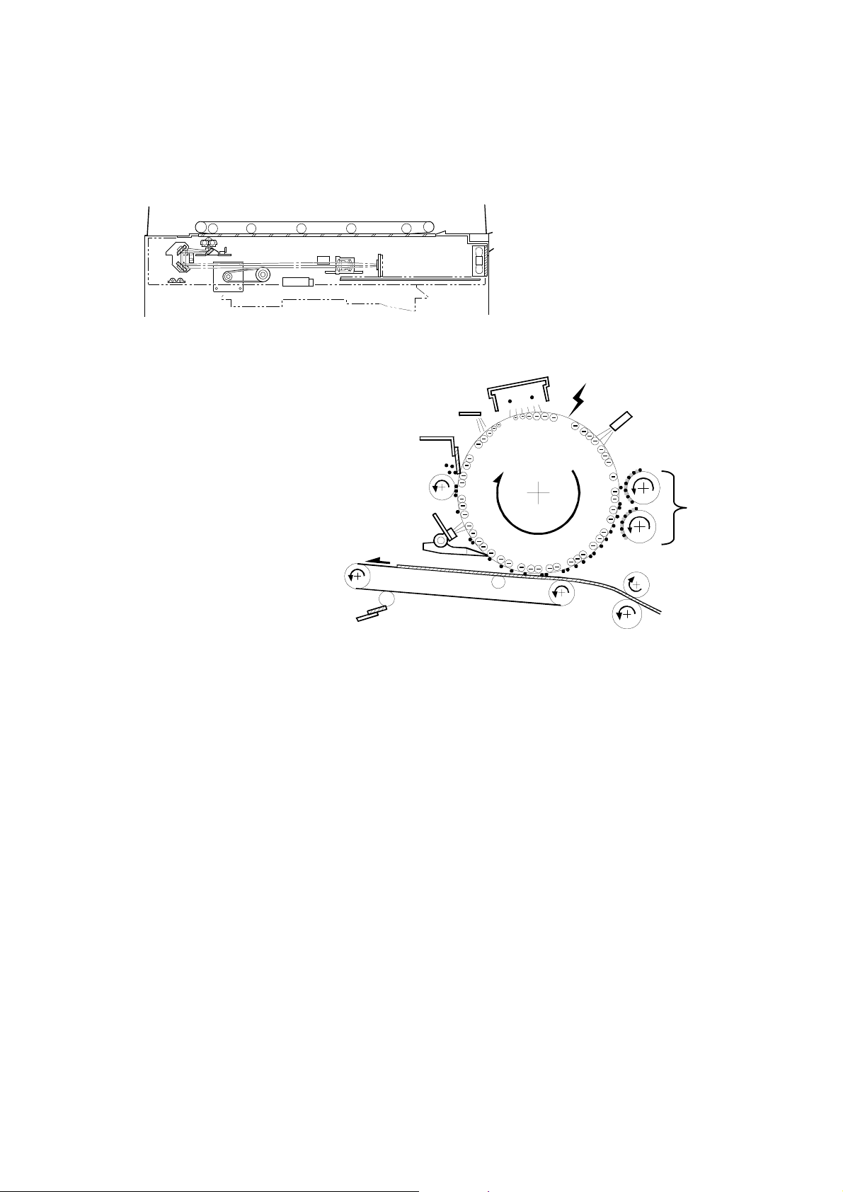
2.2.3 ORIGINAL SIZE DETECTION IN BOOK MODE
[B]
[A]
[C]
A229D534.WMF
[D]
[E]
A229D535.WMF
There are three reflective sensors in the optics cavity for original size detection.
The original width sensor [A] detects the original width, and the original length
sensor-1 [B] and original length sensor-2 [C] detect the original length. These are
the APS (Auto Paper Select) sensors.
Inside each APS sensor, there is an LED [D] and either three photoelectric devices
[E] (for the width sensor) or one photoelectric device (for each length sensor). In
the width sensor, the light generated by the LED is broken up into three beams and
each beam scans a different point of the exposure glass (in each length sensor,
there is only one beam). If the original or DF cover is present over the scanning
point, the beam is reflected and each reflected beam exposes a photoelectric
device and activates it.
While the main switch is on, these sensors are active and the original size data is
always sent to the main CPU. However, the main CPU checks the data only when
the DF is being closed (see the ne xt page).
2-18
Page 44

June 30, 1998 SCANNING
Original Size
A4/A3
Version
LT/DLT Version 2 1 3 4 5
A3 11" x 17"
B4 10" x 14"
F4 8
A4-L 8
" x 14" (8" x 13")
1/2
" x 11" X
1/2
B5-L – X
A5-L 5
A4-S 11" x 8
1/2
" x 8
" X X X X X 00000000
1/2
"XX
1/2
B5-S – X X
A5-S 8
1/2
" x 5
"XX
1/2
Length
Sensor
!!!!!
!!!!!
!!!!!
!!
!!
!!
!!
!!
!!
!!!!!
!!!!
Width Sensor
SP4301
Display
!!
!!
!!
!!
!
!!
!
!!
!!
!!
!
!!
!
!!
00011111
X 00011110
X X 00011100
X X 00001100
X X X 00001000
!!!!!
!!!!!
!!!!
!!
!!
!
!!
!
!!
00000111
X 00000110
X X 00000100
-L: Lengthwise, -S: Sideways, O: High (Paper Present), X: Low
The original size data is taken by the main CPU when the DF position sensor [A] is
activated. This is when the DF is positioned about 15 cm above the exposure
glass. At this time, only the sensor(s) located underneath the original receive the
reflected light and switch on. The other sensor(s) are off. The main CPU can
recognize the original size from the on/off signals from the five sensors.
Detailed
Descriptions
If the copy is made with the platen open, the main CPU decides the original size
from the sensor outputs when the Start key is pressed.
The above table shows the outputs of the sensors for each original size. This
original size detection method eliminates the necessity for a pre-scan and
increases the machine's productivity. However, if the by-pass feeder is used, note
that the machine assumes that the copy paper is lengthwise. For example, if A4
sideways paper is placed on the by-pass tray, the machine thinks it is A3 paper
and scans the full A3 area, disregarding the original size sensors. However, for
each page, the data signal to the laser diode is stopped to match the copy paper
length detected by the registration sensor. This means that copy time for the first
page may be slower (because of the longer time required for scanning), but it will
be normal for the rest of the job.
2-19
Page 45

IMAGE PROCESSING June 30, 1998
2.3 IMAGE PROCESSING
2.3.1 OVERVIEW
Drum
LDDR
LD
Driver
LD
Driver
CCD
LD
Controller
(GAVD)
SBU
IPU
SBICU
Memory
Control ICs
GA1
GA2
HDD
A229D578.WMF
The CCD generates an analog video signal. The SBU (Sensor Board Unit)
converts the analog signal to an 8-bit digital signal, then it sends the digital signal
to the SBICU (Scanner, Base-engine, and Image Processing Control Unit) board.
The SBICU board can be divided into two image processing blocks; the IPU (Image
Processing Unit) and the memory control IC. These two ICs mainly do the
following:
• IPU: Auto shading, filtering, magnification, γ correction, gradation
processing, and video path control
• Memory Controller: Image compression, image rotation, interface with
HDD controller, image repeat, and combine originals
Finally, the SBICU board sends the video data to the LD drive board.
2-20
Page 46

June 30, 1998 IMAGE PROCESSING
2.3.2 SBU
O
CCD
E
SBU
Analog
Processing IC1
Analog
Processing IC2
A/D 1
GA
A/D 2
8 bit data
8 bit data
SBICU
IPU
A229D579.WMF
The CCD converts the light reflected f rom the original into an analog signal. The
CCD line has 5,000 pixels and the resolutio n is 4 00 dpi (15.7 lines/mm).
The CCD has two output lines, for odd and even pixels, to the analog processing
IC. There are two analog processing ICs; one handles odd pixels and the other
handles even pixels. The analog processing IC performs the following operations
on the signals from the CCD.
1. Z/C (Zero Clamp):
Adjusts the black level reference for even pixels to match the odd pixels.
Detailed
Descriptions
2. Signal Amplification
The analog signal is amplified by operational amplifiers in the AGC circuit. The
maximum gains of the operational amplifiers are controlled by the CPU on the
SBICU board.
After the above processes, the analog signals are converted to 8-bit signals by the
A/D converter. This gives a value for each pixel on a scale of 256 grades. Then,
this data goes to the SBICU board. Two 8-bit signals are sent to the SBICU board.
2-21
Page 47

IMAGE PROCESSING June 30, 1998
2.3.3 AUTO IM AGE DENSITY (ADS)
0.5mm
Sub scan direction
[A]
15mm
75mm
A229D581.WMF
This mode prevents the background of an original from appearing on copies.
The copier scans the auto image density detection area [A]. This corresponds to a
narrow strip at one end of the main scan line, as shown in the diagram. As the
scanner scans down the page, the IPU on the SBICU detects the peak white level
for each scan line, within this narrow strip only. From this peak white level, the IPU
determines the reference value for A/D conversion for the scan line. Then, the IPU
sends the reference value to the A/D controller on the SBU.
When an original with a gray background is scanned, the density of the gray area
is the peak white level density. Therefore, the original background will not appear
on copies. Because peak level data is taken for each scan line, ADS corrects for
any changes in background density down the page.
As with previous digital copiers, the user can select manual image density when
selecting auto image density mode and the machine will use both settings when
processing the original.
2-22
Page 48

June 30, 1998 IMAGE PROCESSING
2.3.4 IPU (IMAGE PROCESSING UNIT)
Overview
SBU
GA1
HDD
IPU
GA2
LDDR
LD1
GAVD
LD2
The image data from the SBU goes to the IPU (Image Processing Unit) IC on the
SBICU board, which carries out the following processes on the image data.
1. Auto shading
2. Text/Photo separation
3. Background/Independent dot erase
DRAM
SBICU
A229D580.WMF
Detailed
Descriptions
4. Filtering (MTF and smoothing)
5. Magnification
6. γ correction
7. Grayscale processing
8. Error diffusion
9. Dithering
10. Video path control
11. Test pattern generation
2-23
Page 49

IMAGE PROCESSING June 30, 1998
2.3.5 IMAGE PROCESSING STEPS AND RELATED SP MODES
The following tables shows the image processing path and the related SP modes
used for each image processing mode.
The user can adjust many of the image processing parameters with a UP mode
(Copy Features – General Features – Original Mode Quality Level), using fixed
settings such as Sharp, Normal, and Soft. Each of these fixed settings has different
parameter settings. The user’s changes do not affect the SP mode settings.
If the user is not satisfied with any of the available settings for this UP mode, the
technician can adjust the SP modes. However, the SP mode settings are not used
unless the user selects ‘SP Mode Changed’ with the UP Mode.
Text
Text/Photo
Photo
Pale
Generation
Soft
Photo Mode
Screened Printed
Soft
Soft
Normal
Normal
Normal
Normal
Normal
Sharp
Text Mode
Continuous Tone
Sharp
Sharp
SP Mode Changed
SP Mode Changed
SP Mode Changed
SP Mode Changed
SP Mode Changed
A229D650.WMF
For more details about the settings available for the user, see Service Tables –
Image Quality Setting by UP Mode.
2-24
Page 50

June 30, 1998 IMAGE PROCESSING
Text Mode
In text mode, there is no text/image separation, and the entire image is processed
as a text area. The MTF filtering coefficient and strength can be adjusted
individually for both main and sub scan. Low density originals are produced better
when a stronger MTF filter is selected, but in this case, moiré tends to appear.
With UP Mode (Copy Features – General Features – Original Mode Quality Level),
the user can select ‘Soft’, ‘Normal’, ‘Sharp’, and ‘SP Mode Changed’. The settings
of the SP modes indicated with an asterisk ( * ) are not used unless the user
selects ‘SP Mode Changed’.
Image Processing Steps Related SP Modes
Detailed
Descriptions
Input
Correction 1
Input
Correction 2
Filtering
Magnification
Auto Shading
Background Erase
Independent Dot Erase
MTF
Main Scan
Magnification
SP4903-033 *
(Background Erase Level)
SP4903-028
(Independent Dot Erase Level)
SP4903-011 to 014 *
(MTF Filter Coefficient – Main Scan)
SP4903-020 to 023 *
(MTF Filter Strength – Main Scan)
SP4903-041 to 044 *
(MTF Filter Coefficient – Sub Scan)
SP4903-050 to 053 *
(MTF Filter Strength – Sub Scan)
SP2909-001
(Main Scan Magnification)
ID Control
Gradation
γ Correction
Grayscale Processing
2-25
Page 51

IMAGE PROCESSING June 30, 1998
Photo Mode
There is no text/image separation, and the entire image is processed as a photo
area.
With UP Mode (Copy Features – General Features – Original Mode Quality Level),
the user can select ‘Screen Printed’, ‘Normal’, ‘Continuous Tone’, and ‘SP Mode
Changed’. The settings of the SP modes indicated with an asterisk ( * ) are not
used unless the user selects ‘SP Mode Changed’.
When the user selects “Normal Paper” and “Cont inuous Tone”, error diffusion is
used for the gradation process. However, if the user selects “Screen Printed”,
dither processing is used.
Image Processing Path Related SP Modes
Input
Correction 1
Input
Correction 2
Filtering
Magnification
ID Control
Auto Shading
Smoothing/MTF
Main Scan
Magnification
γ Correction
SP4904-003 *
(Filter Type Selection in Photo
Mode)
SP4903-016 *
(Smoothing Filter Coefficient Level in
Photo Mode)
SP4903-015 *
(MTF Filter Coefficient – Photo
Mode)
SP2909-001
(Main Scan Magnification)
Gradation
Error Diffusion/
Dither Matrix
SP4904-024 *
(Grayscale Process Selection: Dither
or Error Diffusion)
SP4904-002 *
(Dither Matrix Size Selection)
2-26
Page 52

June 30, 1998 IMAGE PROCESSING
Text/Photo Mode
When text/photo mode is selected, text/photo separation is done. A text filter or
photo filter is applied to each image area. The gradation process also depends on
whether the image area is text or photo.
With UP Mode (Copy Features – General Features – Original Mode Quality Level),
the user can select ‘Photo Mode’, ‘Normal’, ‘Text Mode’, and ‘SP Mode Changed’.
The settings of the SP modes indicated with an asterisk ( * ) are not used unless
the user selects ‘SP Mode Changed’.
Image Processing Path Related SP Modes
Detailed
Descriptions
Input
Correction 1
Input
Correction 2
Filtering
Magnification
Auto Shading
Text/Photo Separation
Background Erase
Independent Dot Erase
MTF/Smoothing
Main Scan
Magnification
SP4912-001 to 005 *
Edge Detection Parameters
SP4912-017
(Text/Photo Separation Level)
SP4908 *
Text/Photo Separation Method
SP4903-034 *
(Background Erase Level)
SP4906 *
(Background Erase On/Off)
SP4903-030
(Independent Dot Erase Level)
SP4903-017 *
(MTF Filter Coefficient-Text Areas)
SP4903-047 *
(Filter Type: MTF or Smoothing Photo Areas)
SP2909-001
(Main Scan Magnification)
ID Control
Gradation
γ Correction
Error Diffusion and
Text/Photo Separation
2-27
SP4907 *
(Text/Photo Auto Separation)
SP4904-007 *
(Gradation Process in Text Areas)
SP4904-008 *
(Gradation Process in Photo Areas)
Page 53

IMAGE PROCESSING June 30, 1998
Pale Mode
The image processing for pale mode is basically the same as in text mode.
However, the contrast of the original is low. So, to preserve details, a stronger MTF
filter is used. Also, the independent dot erase level is set at a lower level, so that
only the faintest of dots are deleted; this ensures that dotted lines and periods are
not deleted.
With UP Mode (Copy Features – General Features – Original Mode Quality Level),
the user can select ‘Soft’, ‘Normal’, ‘Sharp’, and ‘SP Mode Changed’. The settings
of the SP modes indicated with an asterisk ( * ) are not used unless the user
selects ‘SP Mode Changed’.
Image Processing Path Related SP Modes
Input
Correction 1
Input
Correction 2
Filtering
Magnification
ID Control
Gradation
Auto Shading
Independent Dot Erase
MTF
Main Scan
Magnification
γ Correction
Grayscale Processing
SP4903-031
(Independent Dot Erase Level)
SP4903-018 *
(MTF Filter Coefficient – Pale
Originals)
SP2909-001
(Main Scan Magnification)
2-28
Page 54

June 30, 1998 IMAGE PROCESSING
Generation Copy Mode
The image processing for generation mode is basically the same as in text mode,
except that in order to prevent lines in the main scan direction from being
reproduced too thickly, line width correction is applied for the final gradation
treatment. Also, to reduce unwanted black dots, a weaker MTF filter is used; this
ensures that isolated dots do not get bigger, and are spread out. These dots will
then be deleted by the independent dot erase feature. This feature, however, is
kept at a low setting to ensure that important details such as dotted lines and
periods are not deleted.
With UP Mode (Copy Features – General Features – Original Mode Quality Level),
the user can select ‘Soft’, ‘Normal’, ‘Sharp’, and ‘SP Mode Changed’. The settings
of the SP modes indicated with an asterisk ( * ) are not used unless the user
selects ‘SP Mode Changed’.
Image Processing Path Related SP Modes
Detailed
Descriptions
Input
Correction 1
Input
Correction 2
Filtering
Magnification
ID Control
Auto Shading
Background Erase
Independent Dot Erase
MTF
Main Scan
Magnification
γ Correction
SP4903-035 *
(Background Erase Level)
SP4903-032
(Independent Dot Erase Level)
SP4903-019 *
(MTF Filter Coefficient – Generation
Copy)
SP2909-001
(Main Scan Magnification)
Gradation
Grayscale
Processing/Line Width
Correction
2-29
SP4904-6 *
(Line Width Correction Type)
Page 55

IMAGE PROCESSING June 30, 1998
2.3.6 AUTO SHADING
A229D645.WMF
Two things happen during auto shading.
Black level correction
The black level is zeroed for each scan line of data by reading the dummy
elements at the end of the CCD signal for each scan line, which should be black.
White level correction
The data is corrected for variations in white level across the main scan. To do this,
a white reference plate is scanned before each original (book mode) or every 30 s
(ADF mode). This corrects for the following effects on each pixel:
• Loss of brightness at the ends of the exposure lamp and the edges of the lens
• Variations in sensitivity among the CCD elements
• Distortions in the light path
2-30
Page 56

June 30, 1998 IMAGE PROCESSING
2.3.7 TEXT/PHOTO AREA SEPARATION
Text/Photo Separation
Auto
Shading
Edge
Determination
Dot Screen
Determination
Final
Evaluation
Filtering
A229D625.WMF
This is used only in text/photo mode.
Text/photo separation is done at two points during image processing. The first one
is immediately after auto shading, and is a complex process involving comparison
with surrounding pixels and the use of matrixes. The second process comes at the
end of the image processing path, and is a simple process that only examines
surrounding pixels as part of the error diffusion process for text/photo mode.
The above drawing shows the data path during the first text/photo area separation
process.
The image data coming in after auto shading is tested by edge determination and
dot screen determination at the same time to separate the image into text and
photo areas. Then the results of both these tests go to a final evaluation, to identify
image and text areas.
Detailed
Descriptions
Edge Determination
Edges of letters and parts of images are detected by checking for strong contrast,
continuity of black pixels, and continuity of white pixels around the black pixels.
The detected edges are treated with an MTF filter, which is part of the text/photo
separation process, and not the same as the one used in the filtering step of the
image processing path.
The filter strength can be changed in the main scan and sub scan directions with
SP mode (SP4912-01 and 02).
After filtering, the edge pixels are divided into four shades (black, dark gray, pale
gray, and white). The threshold levels to distinguish between the shades are
determined by SP4912-003 to 005.
2-31
Page 57

IMAGE PROCESSING June 30, 1998
Dot Screen Determination
The machine determines whether the pixel is in a dot screen area or not. The
process can be adjusted with SP4912-017.
The page is divided into 4 x 4 blocks of pixels. Each block [A] is placed at the
center of a 5 x 3 array of these blocks, and becomes either text or photo,
depending on the other blocks in the 5 x 3 area .
If the number of dot screen blocks in the 5 x 3 area exceeds a threshold, the
central block is determined to be an image area. (The threshold is 2: if two or more
of the blocks in the 5 x 3 area are dot screen, then all the pixels in the central block
are determined to be in an image area.)
[A]
Dot
Screen
Dot
Screen
Dot
Screen
Dot
Screen
Dot
Screen
Dot
Screen
Dot
Screen
Determined to be Photo Determined to be Text
A229D640.WMF
Final Evaluation
The final evaluation depends on the result of dot screen and edge determination as
follows.
Dot Screen Edge Final Evaluation
No No Photo
No Yes Text
Yes No Photo
Yes Yes Photo
The type of filtering to be used depends on the result of the final evaluation.
2-32
Page 58

June 30, 1998 IMAGE PROCESSING
2.3.8 BACKGROUND ERASE
Scanner Output
255
Scanner
0 255
[A]
[B]
(Threshold)
Input
Detailed
Descriptions
A229D591.WMF
By default, this process is used only in text mode, text/photo mode, and generation
copy mode.
Usually, dirty background is erased using Auto Image Density (ADS). However,
sometimes, dirty background areas will still appear. These can be erased by
Background Erase.
If any low image density data which is lower than a threshold level remains after
auto shading, this data will be treated as “0” which is equal to “White”.
By inputting a larger value, darker backgrounds can be eliminated.
The threshold level can be changed with SP mode, as shown below.
SP Mode No. Image Processing Mode Threshold Level (Default)
SP4903-33 Text Mode 15
SP4903-34 Text/Photo Mode 15
SP4903-35 G ener ation Copy Mode 15
Any low image density data lower than this threshold level remaining after auto
shading will be treated as background.
There is not a sudden cutoff at the threshold. Below the threshold [A], the image
data is made paler than it normally would be, until at a certain point [B], it becomes
white. This avoids errors during MTF filtering caused by sudden changes In the
data around the threshold level area.
2-33
Page 59

IMAGE PROCESSING June 30, 1998
2.3.9 INDEPENDENT DOT ERASE
By default, this process is used in all image processing modes except for photo
mode. This function allows independent black dots appearing on copies to be
completely erased, or to be reduced in image density.
As shown in the drawing below, the software compares each pixel with the pixels in
the surrounding 5 x 5 area (except for the immediately adjacent pixels).
If all of the surrounding pixels are smaller than the threshold value (stored in SP4903-28, 30, 31 or 32), the object pixel is either changed to 0 (white) or reduced in
density to an average of the surrounding pixels. This depends on the SP mode
setting.
In the drawing below, the surrounding pixels are all less than 64. If the SP mode
value is “12”, the object pixel value is reduced from “50” to “30”, the average value
of the surrounding pixels. If the SP mode value is “4”, the object pixel is deleted
(changed to white).
20
30
0 3070
40203040
30
50
Object pixel
Surrounding pixels to be used for
30
60
50
20 300
30
2010
calculation
0
3030403020
Ignored pixels
A229D592.WMF
Average of surrounding pixels:
(20 + 40 + 30 + 20 + 40 +30 + 30 + 30 + 30 + 60 + 0 + 20 + 30 + 40 + 30 + 30) / 16
= 30
2-34
Page 60

June 30, 1998 IMAGE PROCESSING
The threshold level for deciding whether a dot is independent can be changed
using SP mode. The default value of this threshold level is different for each image
processing mode. As shown below, in Text/Photo mode, independent dots are
reduced, but in Text, Pale, or Generation mode, they are erased.
SP Mode No. Image Processing Mode Default Value (SP Setting)
SP4903-28 Text Mode 2
SP4903-30 Text/Photo Mode 9
SP4903-31 Pale Mode 1
SP4903-32 Generation Mode 1
NOTE: Settings 0 and 8: Disable this function.
Settings 1 to 7: Erase detected independent dots
Settings 9 to 15: Reduce the density of detected independent dots
Each SP mode has 16 possible settings, as follows.
(A = Surrounding pixel with the highest value)
Detailed
Descriptions
SP mode
value
0 Disabled 8 Disabled
1
2 If A < 32, the central pixel is
3 If A < 48, the central pixel is
4
5
6 If A < 96, the central pixel is
7 If A < 128, the central pixel is
If A < 16, the central pixel is
deleted (changed to white)
deleted (changed to white)
deleted (changed to white)
If A < 64, the central pixel is
deleted (changed to white)
If A < 80, the central pixel is
deleted (changed to white)
deleted (changed to white)
deleted (changed to white)
Function
SP mode
value
9
10 If A < 32, the density is
11 If A < 48, the density is
12
13
14 If A < 96, the density is
15 If A < 128, the density is
Function
If A < 16, the density is
reduced to the average
reduced to the average
reduced to the average
If A < 64, the density is
reduced to the average
If A < 80, the density is
reduced to the average
reduced to the average
reduced to the average
2-35
Page 61

IMAGE PROCESSING June 30, 1998
2.3.10 FILTERING, MAIN SCAN MAGNIFICATION/REDUCTION
Overview
After auto shading, the image data is processed by both filtering and main scan
magnification. However, to reduce the occurrence of moiré in the image, the
processing order depends on the reproduction ratio, as follows.
1. 64% reduction or less
Main Scan Reduction → Filtering
2. 65% reduction or higher
Filtering → Main Scan Magnification
Filtering
By default, an individual MTF filter is used for each image processing mode, to
enhance the desired image qualities. (For photo mode, smoothing filter is selected
as the defau lt setting.)
A stronger MTF filter emphasizes sharpness and leads to better reproduction of
low image density areas, but may lead to the occurrence of moiré in the image.
When adjusting a filter, adjust the coefficient first. If that does not satisfy the user,
then adjust the strength (it may be necessary to do some fine tuning with the
coefficient after adjusting the strength ).
For text mode, the filter coefficient and strength can be adjusted in the main scan
and sub scan directions individually. This allows the copy quality to be adjusted
more precisely, to match the originals normally scanned by a particular customer.
Example: In a case when vertical lines (sub scan) are reproduced clearly, but
horizontal lines (main scan) are not reproduced clearly, the technician can adjust
the main scan filter only.
For photo mode, the smoothing filter is the default filter, but the MTF filter may be
selected by SP mode. This is effective when putting more weight on improving the
resolution when copying from “continuous tone” originals.
For text/photo mode, a different MTF filter is applied for the text and photo areas
that were determined during text/photo separation. The filter type for each area
may be changed with SP mode. This is done in SP4903-017 for text areas, and
SP4903-047 for photo areas.
2-36
Page 62

June 30, 1998 IMAGE PROCESSING
Main scan magnification/reduction
A229D646.WMF
Detailed
Descriptions
Reduction and enlargement in the sub scan direction are done by changing the
scanner speed. However, reduction and enlargement in the main scan direction
are handled by the IPU chip on the SBICU board.
Scanning and laser writing are done at a fixed pitch (the CCD elements cannot be
squeezed or expanded). So, to reduce or enlarge an image, imaginary points are
calculated that would correspond to a physical enlargement or reduction of the
image. The correct image density is then calculated for each of the imaginary
points based on the image data of the nearest four true points. The calculated
image data then becomes the new (reduced or enlarged) image data.
Main scan magnification can be disabled with SP 4903-5 to test the IPU IC.
2-37
Page 63

IMAGE PROCESSING June 30, 1998
2.3.11 GAMMA (γγγγ) CORRECTION
Gamma correction ensures accurate generation of the various shades in the gray
scale from black to white, accounting for the characteristics of the scanner and
printer.
Scanner gamma correction corrects the data output to the IPU to account for the
characteristics of the scanner (e.g., CCD response, scanner optics).
Printer gamma correction corrects the data output from the IPU to the laser diode
to account for the characteristics of the printer (e.g., the characteristics of the drum,
laser diode, and lenses).
The data for the scanner and printer gamma correction are fixed and stored in the
memory. There are no SP adjustments in this machine.
2.3.12 GRADATION PROCESSING
There are two basic types of gradation processing
• Printing multi-bit per pixel data as it is (i.e., keeping many image density levels
available for each pixel; in this machine)
• Reducing the number of possible output levels per pixel, by using only a few of
the range of possible output levels
Various processes are available to try to reproduce various types of original as
faithfully as possible.
In this model, these are three processes:
1. Grayscale processing
2. Error diffusion
3. Dithering
These three processes are used as follows (default setting).
Text mode Grayscale processing
Text/photo mode: Error diffusion
Photo mode: Error diffusion or dithering
Generation Copy Mode: Grayscale processing + line width correction
Pale mode: Grayscale processing
The above information is expressed in the diagram in the Image Processing Path
section.
2-38
Page 64

June 30, 1998 IMAGE PROCESSING
Error Diffusion and Dithering
The error diffusion process reduces the difference in contrast between light and
dark areas of a halftone image. Each pixel is corrected using the difference
between it and the surrounding pixels. The corrected pixels are then corrected
using an error diffusion matrix.
In the dithering process, each pixel is compared with a pixel in a dither matrix.
Several matrixes are available, to increase or decrease the detail on the copy.
Comparing with dithering, error diffusion gives a better resolution, and is more
suitable for “continuous toned” originals. On the other hand, dithering is more
suitable for “screen printed” originals.
In Photo Mode, when the user selects “Normal Paper” and “Continuous Tone”,
error diffusion is used. However, if the user selects “Screen Printed”, dither
processing is used. If the user selects ‘SP Mode Changed’, then either dithering or
one of two types of error diffusion can be selected with SP4904-024,. When
dithering is selected, the setting of SP4904-002 will decide which dithering matrix is
used.
In Text/Photo Mode, the error diffusion process that is used depends on the image
area type (text or photo) as shown below. Therefore, before error diffusion, a
simple text/photo separation process is performed (as mentioned earlier, in the
Text/Photo Separation section).
Area Error Diffusion Type Related SP Mode
Text Area
Photo Area
1 dot error diffusion
2 dot error diffusion
SP4904-007
SP4904-008
Grayscale Processing
The eight-bit data arriving from the gamma correction circuit is passed on
unchanged.
Detailed
Descriptions
2-39
Page 65

IMAGE PROCESSING June 30, 1998
2.3.13 LINE WIDTH CORRECTION
This function is effective only in generation copy mode.
Usually, lines will bulge in the main scan direction as a result of the
negative/positive development system that is used in this model. So, pixels on
edges between black and white areas are compared with adjacent pixels, and if the
pixel is on a line, the line thickness will be reduced.
The line width correction is done in the IPU chip.
The line width correction type can be selected with SP4904-6.
2-40
Page 66

June 30, 1998 IMAGE PROCESSING
2.3.14 COMPRESSION AND STORAGE
Circuit
FIFO
IPU
GA 1
GA 2
HDD
Detailed
Descriptions
2M
DRAM
2M
DRAM
2M
DRAM
2M
DRAM
2M
DRAM
2M
DRAM
A229D626.WMF
The compression and storage circuit consists of the GA1 IC, GA2 IC, DRAM, and
the hard disk drive. The functions of each device are as follows.
GA 1: C ompressing/decompressing the 8- bit image data
Image rotation
Image data transfer to the HDD, FIFO memory, and GA2
Controls the HDD
GA 2: C ompressing a nd decompressing the image data
Image rotation
Image transfer to the DRAM, and GA 1
Image repeat
Image combine
DRAM (12 MB): Stores compressed data from GA1
Hard Disk Drive:
Stores compressed data
Electrical sort
Misfeed back-up
2-41
Page 67

IMAGE PROCESSING June 30, 1998
Compression
A229D627.WMF
After image processing, the image data from the IPU first goes to the FIFO block.
This block consists of 14 FIFO memories (7 for data input, 7 for data output).
FIFOs are used because four scan lines are compressed at the same time to
improve the image compression speed.
The image data then goes to the GA1 IC, where the image data for a whole page is
divided into many blocks (the block size is 4 x 4 pixels) as shown above left. Then,
each block is compressed and sent to DRAM through GA2 to store the data.
When the HDD is ready to receive the data, th e data passes to GA2 where it is
compressed some more, and sent to the HDD.
When it is time to output the data, the data flow is reversed, and the data is
decompressed. The decompressed data goes back to the FIFO block.
Image Rotation
This copier contains 12 MB of DRAM. This is enough to hold two A4 (LT) size
images (this allows the user to scan one original while printing another).
2-42
Page 68

June 30, 1998 LASER EXPOSURE
2.4 LASER EXPOSURE
2.4.1 OVERVIEW
This machine uses two laser diodes to produce electrostatic images on an OPC
drum. The laser diode unit converts image data from the SBICU board into laser
pulses, and the optical components direct these pulses to the drum.
Exposure of the drum by the laser beam creates the latent image. The laser beam
makes the main scan while drum rotation controls the sub scan.
The combined strength of both beams is 0.5 mW on the drum surface at a
wavelength of 780 nm.
The polygon motor speed is as follows.
Detailed
Descriptions
Resolution Modes
400 dpi Copy, Printer Approx. 25984
600 dpi Printer Approx. 38976
Motor Speed
(rpm)
There are up to 16 image density levels for each pixel. To realize this, this machine
uses a form of pulse width modulation. In this machine, pulse width modulation
consists of the following processes:
• Laser diode pulse positioning
• Laser diode power/pulse width modulation
Laser diode power and pulse width modulation is done by the laser diode drive
board (LDDR). Briefly, the width of the laser pulse for a pixel depends on the output
level (from 0 to 15) required for the pixel.
This machine can also change the laser pulse position (at the left side of the pixel,
at the center, or at the right side) automatically, depending on the location of the
image pixel so that the edges of characters and lines become cleaner. There is no
SP mode adjustment for this, unlike in some earlier models.
2-43
Page 69

LASER EXPOSURE June 30, 1998
2.4.2 OPTICAL PATH
[C]
[A]
[D]
[B]
[F]
[E]
[H]
[G]
[I]
[J]
A229D522.WMF
The output path from the laser diode to the drum is shown above.
The LD unit [A] outputs two laser beams to the polygonal mirror [B] (six mirrors)
through the cylindrical lens [C] and the 1st mirror [D].
Each surface of the polygon mirror reflects two full main scan lines. The laser
beams go to the F-theta mirror [E], mirror [F], BTL (barrel toroidal lens) [G], and
mirror [H]. Then these laser beams go to the drum through the toner shield glass
[I].
The laser synchronizing detector [J] determines the main scan starting position.
2-44
Page 70

June 30, 1998 LASER EXPOSURE
2.4.3 AUTO POWER CONTROL
cкзен=`зоЙк=p~СЙну=pпбнЕЬ
p_f`r
p_f`r
p_f`rp_f`r
HRs
bêêçê
sfabl
ialcc
ibsbiN
d^sa
d^sa
d^sad^sa
Ef`=TF
Ef`=TF
Ef`=TFEf`=TF
HRsia
ibsbiO
sfabl
obcN
sfabl
obcO
f`=O
f`=O
f`=Of`=O
f`=P
f`=P
f`=Pf`=P
m_
ia
m_
ia
bêêçê
ma
ma
mama
ma
ma
mama
ia
ia
iaia
iaN
iaN
iaNiaN
HRsia
ia
ia
iaia
iaO
iaO
iaOiaO
Detailed
Descriptions
iaao
iaao
iaaoiaao
bêêçê
A229D523.WMF
IC2 and IC3 on the LDDR drive the laser diodes. Even if a con s tant electric current
is applied to the laser diode, the intensity of the output light changes with the
temperature. The intensity of the output decreases as the temperature increases.
In order to keep the output level constant, IC2 and IC3 monitor the current passing
through the photodiode (PD). Then they increase or decrease the current to the
laser diode as necessary, comparing it with the reference levels (REF1 and REF2).
This auto power control is done just after the machine is turned on and during
printing while the laser diode is active.
The reference levels are adjusted on the production line. Do not touch the variable
resistors on the LDDR in the field.
2-45
Page 71

LASER EXPOSURE June 30, 1998
2.4.4 DU AL BEAM WRITING
[D]
[E]
[B]
[C]
[A]
[D]
A229D524.WMF
This LD unit has two laser diodes; LD1 [A] and LD2 [B] for writing the image. This
means that each face of the polygon mirror writes two main scan lines, and twelve
main scans are produced when the polygon mirror rotates once. The reasons for
this mechanism are as follows.
1) To reduce the polygon motor rotation speed
2) To reduce the noise generated by the polygon motor
3) To reduce the frequency of the image data clock
Two laser beams are transferred to the polygon mirror [C] through collimating lens
[D] and prism [E]. The two laser beams arrive on the drum surface about 2 mm
away from each other in the main scan direction and about 0.06 mm (at 400 dpi) in
the sub scan direction (see the next page).
The reason for the two-mm difference in the main scan direction is so that the
machine can detect a laser synchronization signal for each beam.
2-46
Page 72

June 30, 1998 LASER EXPOSURE
2.4.5 LASER BEAM PITCH CHANGE MECHANISM
2 mm
P1
P2
[C]
P1: 400 dpi
P2: 600 dpi
A229D525.WMF
[B]
[D]
[A]
A229D516.WMF
A printer option is available for this machine and the resolution of the printer is 600
dpi. The machine changes the resolution between 400 and 600 dpi by rotating the
LD unit.
Detailed
Descriptions
When the LD positioning motor [A] turns, the metal block [B] (wh i ch contacts the
LD unit housing [C]) moves up and down. This changes the position of the L2 laser
beam (L1 does not move).
Both LD unit positions are at fixed distances from the LD home position sensor [D]
(measured by motor pulses). Usually, the LD unit moves directly to the proper
position. However, when the number of times that the resolution has changed
reaches the value of SP2-109-5, the LD unit moves to the home position (the home
position sensor activates), then it moves to the proper position. This recalibrates
the LD unit positioning mechanism.
2-47
Page 73

LASER EXPOSURE June 30, 1998
2.4.6 LD SAFETY SWITCHES
SBICU
CN307-2
PSU
+5V
-1
CN124-3 CN301-8
LDDR
CN402-3
CN402-4
LD2
+5V
LD5V
LD1
Front Cover
Safety Sw
CN403-1
CN403-3
A229D500.WMF
To ensure technician and user safety and to prevent the laser beam from
inadvertently switching on during servicing, there are two safety switches located at
the front cover. These two switches are installed in series on the LD5 V line coming
from the power supply unit (PSU) through the SBICU board.
When the front cover or the upper right cover is opened, the power supply to the
laser diode is interrupted.
2-48
Page 74

June 30, 1998 DRUM UNIT
2.5 DRUM UNIT
2.5.1 PROCESS CONTROL
Overview
The drum potential will gradually change because of the following factors.
• Dirty optics or exposure glass
• Dirty charge corona casing and grid plate
• Changes in drum sensitivity
To maintain good copy quality, the machine does the following just after the main
switch has been turned on (if the fusing temperature is less than 100 °C and SP3901 is on).
1) Potential Sensor Calibration
2) V
Adjustment
SG
3) VG(Grid Voltage) Adjustment
4) LD Power Adjustment
5) V
REF
Update
This process is known as ‘Process Control Initial Setting’. The rest of this section
will describe these steps in more detail.
Processes 1, 3, and 4 in the above list compensate for changes in drum potential.
Processes 2 and 5 are for toner density control; see the “Development and Toner
Supply” section for more details .
Detailed
Descriptions
2-49
Page 75

DRUM UNIT June 30, 1998
Drum potential sensor calibration
[A]
[D]
RA101
-200/-700
[B]
RA102
A229D641.WMF
[C]
The drum potential sensor [A] detects the electric potential of the drum surface [B].
Since the output of the sensor is affected by environmental conditions, such as
temperature and humidity, the sensor needs recalibration at times. This is done
during process control initial setting.
The development power pack [C] has two relay contacts. Usually RA102 grounds
the drum. However, to calibrate the sensor, the SBICU switches RA102 and RA101
over, which applies the power pack output voltage to the drum shaft [D].
The machine automatically calibrates the drum potential sensor by measuring the
output of the sensor when –200V and –700V are applied to the drum. From these
two readings, the machine can determine the actual drum potential from the
potential sensor output that is measured during operation.
During calibration, if the rate of change in drum potential sensor response to
applied voltage is out of the target range, SC370 is logged and auto process
control turns off. The VG and LD power adjustments are skipped; VG is set to the
value stored in SP2-001-01, and LD power is set to the values stored in SP2-103.
VSG adjustment
This calibrates the ID sensor output for a bare drum to 4.0 ± 0.2V. It does this by
changing the intensity of the light shining on the drum from the sensor. This is done
automatically during process control initial setting, and it can also be done
manually with SP3-001-002.
If the ID sensor output cannot be adjusted to within the standard, SC350 is logged
and toner density control is done using the TD sensor only.
For details of how the machine determines an abnormal sensor detection, see
section 7 (Troubleshooting) .
2-50
Page 76

June 30, 1998 DRUM UNIT
VG Adjustment
Charge/Grid
P.P
SBICU
[A]
A229D642.WMF
Detailed
Descriptions
The potential on unexposed areas of the drum (VD) gradually changes during drum
life. To keep VD constant, the grid voltage (VG) is adjusted during process control
initial setting.
The SBICU checks VD using the drum potential sensor [A]. If it is not within the
target range (-900V +– 10V), the SBICU adjusts VG (Grid Voltage) through the
Charge/Grid power pack to get the correct target voltage.
The most recently detected values can be displayed with SP3-902-2 (VD) and 3902-4 (VG).
If the CPU cannot get VD within the target range by changing VG, VG is set to the
previous value and SC 370 is logged.
For details of how the machine determines an abnormal sensor detection, see
section 7 (Troubleshooting) .
2-51
Page 77

DRUM UNIT June 30, 1998
LD power adjustment
LDDR
SBICU
A229D643.WMF
This adjustment uses the drum potential sensor to keep the ID sensor pattern at
the same density, so that V
will be updated correctly (see the next page).
REF
The VH pattern is developed using the current LD power (the density is the same
as the ID sensor pattern). The drum potential sensor detects the potential on this
pattern. The LD power is adjusted until VH becomes –300V +–20V.
This is done only during process con t rol initial setting.
The latest VH can be displayed using SP3-902-3. The corrected LD power can be
displayed using SP3-902-5 (the default is stored in SP2-103-1-4). See “Laser
exposure” for more details about l aser power.
If VH cannot be adjusted to within the standard within 25 attempts, LD power is set
to the latest value (the one used for the 25th attempt) and SC 370 is logged.
For details of how the machine determines an abnormal sensor detection, see
section 7 (Troubleshooting) .
2-52
Page 78

June 30, 1998 DRUM UNIT
REF
V
Update
The TD sensor reference voltage (V
) is updated to stabilize the concentration of
REF
toner in the development unit as follows;
New V
∆V
REF
REF
V
(A)
= Current V
REF
REF
+ ∆V
REF
is determined using the following Vsp/Vsg and V
Vsp/Vsg (B)
B < 0.055 0.055 < B =< 0.07
– V
T
A =< –0.2
–0.2< A =<–0.1
:
:
0.2 < A
0.25 0.22 : –0.03
0.25 0.22 : –0.05
:
:
0 0.05 : –0.25
:
:
REF– VT
⋅ ⋅ ⋅ ⋅ ⋅ ⋅ ⋅ ⋅ ⋅
:
:
table
VT : TD Sensor Output
When SC350 (ID Sensor Abnormal) is generated, V
is not updated. The
REF
machine uses the current value.
V
is updated during process control initial setting. It is also updated if both of
REF
the following conditions exi st:
0.15 < B
:
:
Detailed
Descriptions
• 50 or more copies have been made since the last V
• The copy job is finished
REF
update
2-53
Page 79

DRUM UNIT June 30, 1998
2.5.2 DRUM UNIT COMPONENTS
1098
1
7
6
5
4
3
A229D554.WMF
The drum unit consists of the components shown in the above illustration. An
organic photoconductor drum (diameter: 100 mm) is used for this model.
1. OPC Drum
6. Cleaning Brush
2
2. Drum Potential Sensor
3. Pick-off Pawl
4. Image Density Sensor
5. Toner Collection Coil
7. Cleaning Blade
8. Charge Power Pack
9. Quenching Lamp
10. Charge Corona Unit
2-54
Page 80

June 30, 1998 DRUM UNIT
2.5.3 DRIVE MECHANISM
[C]
[A]
[B]
[D]
Detailed
Descriptions
[E]
A229D555.WMF
The drive from the drum motor [A] is transmitted to the drum, the cleaning unit and
the toner recycling unit [D] through some timing belts, gears, the drum drive shaft
[B], and the cleaning unit coupling [C].
The drum motor has a drive controller, which outputs a motor lock signal when the
rotation speed is out of the specified range.
The fly-wheel [E] on the end of the drum drive shaft stabilizes the rotation speed.
2-55
Page 81

DRUM UNIT June 30, 1998
2.5.4 DRUM CHARGE
Overview
[A]
A229D557.WMF
This copier uses a double corona wire scorotron system to charge the drum. Two
corona wires are needed to give a sufficient negative charge to the drum surface.
The stainless steel grid plate makes the corona charge uniform and controls the
amount of negative charge on the drum surface by applying a negative grid bias
voltage.
The charge power pack [A] gives a constant corona current to the corona wires
(-1200 µA).
The bias voltage to the grid plate is automatically controlled to maintain the correct
image density in response to changes in drum potential caused by dirt on the grid
plate and charge corona casing. This is described in the Process Control section in
more detail.
2-56
Page 82

June 30, 1998 DRUM UNIT
Charge Corona Wire Cleaning Mechanism
[A]
[A]
[C]
[B]
Detailed
Descriptions
A229D558.WMF
Air flowing around the charge corona wire may deposit toner particles on the
corona wires. These particles may interfere with charging and cause low density
bands on copies.
The wire cleaner pads [A] automatically clean the wires to prevent such a problem.
The wire cleaner is driven by a dc motor [B]. Normally the wire cleaner [C] is
located at the front end (this is the home position). Just after the main switch is
turned on, the wire cleaner motor turns on to bring the wire cleaner to the rear and
then back to the home position. When the wire cleaner moves from the rear to the
home position (black arrow in the illustration), the wire cleaner pads clean the
wires. This is only done when 5000 or more copies have been made since the
wires were cleaned last, but only if the fusing temperature is less than 100 °C
2-57
Page 83

DRUM UNIT June 30, 1998
2.5.5 DRUM CLEANING AND TONER RECYCLING
Overview
[C]
[A]
[B]
[A]
[A]
4 mm
[D]
A229D560.WMF
[B]
A229D561.WMF
[B]
This copier uses a counter blade system to clean the drum. In a counter blade
system, the drum cleaning blade [A] is angled against drum rotation. The counter
blade system has the following advantages:
• Less wearing of the cleaning blade edge
• High cleaning efficiency
Due to the high efficiency of this cleaning system, the pre-cleaning corona and
cleaning bias are not used for this copier.
The cleaning brush [B] supports the cleaning blade. The brush removes toner from
the drum surface and any remaining toner is scraped off by the cleaning blade.
Toner on the cleaning brush is scraped off by the mylar [C] and falls onto the toner
collection coil [D]. The coil transports the toner to the toner collector bottle.
To remove any accumulated toner at the edge of the cleaning blade, the drum
turns in reverse for about 4 mm at the end of every copy job. The accumulated
toner is deposited on the drum and is removed by the cleaning brush.
2-58
Page 84

June 30, 1998 DRUM UNIT
Drive Mechanism
[C]
[E]
[A]
[B]
[E]
Detailed
Descriptions
[D]
A229D562.WMF
Drive from the drum motor is transmitted to the cleaning unit drive gear via the
timing belt [A] and the cleaning unit coupling [B]. The cleaning unit drive gear [C]
then transmits the drive to the front through the cleaning brush [D]. The gear at the
front drives the toner collection coil gear [E].
2-59
Page 85

DRUM UNIT June 30, 1998
Cleaning Blade Pressure Mechanism and Side-to-Side Movement
[C]
[D]
[A]
[B]
A229D563.WMF
[D]
The spring [A] always pushes the cleaning blade against the drum. The cleaning
blade pressure can be manually released by pushing up the release lever [B]. To
prevent cleaning blade deformation during transportation, the release lever must
be locked in the pressure release (upper) position.
The pin [C] at the rear end of the cleaning blade holder touches the cam gear [D],
which moves the blade from side to side. This mov ement helps to disperse
accumulated toner to prevent early blade edge wear.
2-60
Page 86

June 30, 1998 DRUM UNIT
Toner Recycling and Waste Toner Collection Mechanism
Toner Recycling
[K]
[J]
[A]
[I]
[H]
A229D630.WMF
[E]
[D]
[C]
[G]
[B]
[E]
[L]
[F]
Detailed
Descriptions
[D]
[F]
[G]
A229D628.WMF
This machine has a toner recycling system, using a screw-pump unit. This
mechanism reduces the amount of waste toner by 90%.
Only toner which is transferred from the drum cleaning blade is recycled. Toner
collected from the transfer belt cleaning blade is not recycled, but is transported to
the toner collection bottle for waste toner through the toner collection tube [A].
The toner recycling unit is driven by the drum motor via timing belts, gears and the
toner recycling clutch [B].
The recycled toner from the drum collected by the cleaning coil [C] is dropped on
the screw [D] in the toner recycling unit, then transported to the screw-pump [E].
The screw-pump consists of the rotor [F] and the stator [G]. The rotor turns inside
the stator, and pushes the recycled toner through the screw-pump as shown. The
toner recycling motor [H] drives the air pump [I] This pump blows the toner out of
the screw-pump through the toner recycling tube [J] towards the development unit
[K].
The toner recycling sensor [L] monitors the rotation of the drive gear. If toner is
clogged and the coil cannot move when the motor is switched on, an SC495 is
generated.
2-61
Page 87

DRUM UNIT June 30, 1998
[C]
[D]
[B]
To the Toner Collection
Bottle (Waste Toner)
[A]
To the Toner Supply
Unit (Recycled
Toner)
A229D629.WMF
The toner recycling unit mechanism is controlled by the image pixel count. The
recycling clutch [A] is engaged for 2 seconds after making the equivalent of about
100 copies of a 6% test chart. The air pump also turns on for 6 seconds at the
same interval.
When the recycled toner cannot be transported to the development unit (for
example, if the toner recycling clutch is slipping or toner is clogged in the tube or
the screw pump), the recycling unit [B] starts to fill up with recycled toner
The tower above the recycling unit is divided into two partitions. The right-hand
partition contains toner from the drum cleaning unit, and the left-hand partition
contains toner from the transfer belt cleaning unit.
The wall between the partitions contains agitators [C] that prevent toner from
completely filling the right-hand partition if the recycling mechanism gets clogged
with toner. The agitators move sideways, and any toner that is piled too high
moves into the toner collection tube [D]. This toner is transported to the toner
collection bottle as waste toner.
2-62
Page 88

June 30, 1998 DRUM UNIT
[G]
Waste Toner Collection
[B]
[C]
[D]
Detailed
Descriptions
[F]
[J]
[E]
[I]
[A]
A229D633.WMF
[H]
A229D634.WMF
Toner collected by the transfer belt unit is transported to the toner collection bottle
[A] through the toner collection tube. Three helical coils transport the toner.
One coil [B] feeds the toner in from the transfer belt unit. The next coil [C], driven
by the drum motor via drive belts, feeds the toner through the toner collection tube,
and the final coil [D], driven by the toner collection motor [E], feeds the toner to the
toner collection bottle. This toner is to be disposed of as waste.
The toner collection motor sensor [F] monitors the rotation of the toner collection
coil using the actuator disk [G] to prevent the coil from being damaged by toner
clogged in the collection tube.
When the toner collection bottle becomes full, the tone r pressure in the bottle
increases and presses the gear [H] against the toner overflow switch [I]. After the
toner overflow switch is activated, the copy job is allowed to end, or up to 100
continuous copies can be made, then copying is disabled and the service call "full
toner collection bottle" is displayed on the LCD.
This condition can be cleared by de-actuating the toner overflow switch while deactuating then actuating the toner collection bottle switch [J].
2-63
Page 89

DRUM UNIT June 30, 1998
2.5.6 OTHERS
Air Flow Around the Drum
[A]
[C]
[B]
A229D565.WMF
The exhaust fan [A] located above the fusing unit provides air flow to the charge
corona unit to prevent uneven build-up of negative ions that can cause uneven
drum surface charge.
An ozone filter [B] absorbs the ozone around the drum.
The exhaust fan turns slowly during stand-by and turns quickly during copying to
keep the temperature inside the machine constant.
To prevent foreign matter from entering the copier inside, there is a dust protection
filter in the entrance [C] of the duct.
2-64
Page 90

June 30, 1998 DRUM UNIT
Pick-off Mechanism
[B]
[A]
Detailed
Descriptions
[B]
A229D559.WMF
The pick-off pawls are always in contact with the drum surface as a result of weak
spring pressure. They move from side to side during the copy cycle to prevent
drum wear at any particular location. This movement is made via a shaft [A] and an
a cam [B].
2-65
Page 91

DRUM UNIT June 30, 1998
Quenching
[A]
A229D556.WMF
In preparation for the next copy cycle, light from the quenching lamp [A] neutralizes
any charge remaining on the drum.
The quenching lamp consists of a line of 16 red LEDs extending across the full
width of the drum.
2-66
Page 92

June 30, 1998 DEVELOPMENT AND TONER SUPPLY
2.6 DEVELOPMENT AND TONER SUPPLY
2.6.1 OVERVIEW
[L]
[G]
[B]
[C]
[A]
A229D566.WMF
[D]
• Paddle Roller [A]
• Upper Development Roller [B]
• Lower Development Roller [C]
• Toner Density Sensor [D]
• Developer Agitator [E]
• Toner Auger [F]
[E]
[F]
[H]
[I]
• Development Filter [G]
• Toner Supply Motor [H]
• Toner End Sensor [I]
• Toner Agitator [J]
• Toner Supply Roller [K]
• Toner Hopper [L]
Detailed
Descriptions
[L]
[J]
[K]
A229D567.WMF
This copier uses a double roller de velo pment (DRD) system. Each roller has a
diameter of 20 mm.
This system differs from single roller development systems in that:
(1) It develops the image in a narrower area
(2) It develops the image twice
(3) The relative speed of each development roller against the drum is reduced.
Also, this machine uses fine toner (about 7.5 µm) and developer (about 70 µm).
Both the DRD system and new consumables improve the image quality, especially
of thin horizontal lines, the trailing edges of the half-tone areas, and black cross
points.
The machine contains a toner recycling system. The recycled toner is carried to the
toner hopper [L] by the toner recycling motor and mixed with new toner by the toner
agitator [J]. (The toner recycling system is described in the “Drum Cleaning And
Toner Recycling section”.)
2-67
Page 93

DEVELOPMENT AND TONER SUPPLY June 30, 1998
2.6.2 DEVELOPMENT MECHANISM
[C]
[B]
[D]
[A]
A229D568.WMF
The paddle roller [A] picks up developer and transports it to the upper development
roller [B]. Internal permanent magnets in the development rollers attract the
developer to the development roller sleeve. The upper development roller carries
the developer past the doctor blade [C]. The doctor blade trims the developer to
the desired thickness and creates backspill to the cross mixing mechanism.
In this machine, black areas of the latent image are at a low negative charge
(about –150 V) and white areas are at a high negative charge (about –950 V).
The development roller is given a negative bias to attract negatively charged toner
to the black areas of the latent image on the drum.
The development rollers continue to turn, carrying the developer to the drum [D].
When the developer brush contacts the drum surface, the low-negatively charged
areas of the drum surface attract and hold the negatively charged toner. In this
way, the latent image is developed.
2-68
Page 94

June 30, 1998 DEVELOPMENT AND TONER SUPPLY
2.6.3 DRIVE MECHANISM
[C]
[D]
[E]
Detailed
Descriptions
[B]
[A]
A229D569.WMF
The gears of the development unit are driven by the development drive gear [A]
when the development motor [B] (a dc servomotor) turns.
The gears of the toner hopper are driven by the toner supply roller drive gear [C]
when the toner supply clutch [D] activates.
The above gears are helical gears. Helical gears are more quiet than normal gears.
The teeth of the development drive gear are chamfered so that they smoothly
engage the development roller gear [E] when the unit is installed.
2-69
Page 95

DEVELOPMENT AND TONER SUPPLY June 30, 1998
2.6.4 CROSSMIXING
[C]
[B]
[E]
[F]
[A]
[D]
A229D570.WMF
[C]
[E]
[B]
[F]
[A]
[D]
A229D571.WMF
This copier uses a standard cross-mixing mechanism to keep the toner and
developer evenly mix ed. It also helps ag i tate the developer to prevent developer
clumps from forming and helps create the triboelectric charge.
The developer on the turning development rollers [A] is split into two parts by the
doctor blade [B]. The part that stays on the development rollers forms the magnetic
brush and develops the latent image on the drum. The part that is trimmed off by
the doctor blade goes to the backspill plate [C].
As the developer slides down the backspill plate to the agitator [D], the mixing
vanes [E] move it slightly toward the rear of the unit. Part of the developer falls into
the auger inlet and is transported to the front of the unit by the auger [F].
The agitator moves the developer slightly to the front as it turns, so the developer
stays level in the development unit.
2-70
Page 96

June 30, 1998 DEVELOPMENT AND TONER SUPPLY
2.6.5 DEVELOPMENT BIAS
[A]
[B]
[C]
A229D572.WMF
To attract negatively charged toner to the black areas of the latent image on the
drum, the development power pack [A] applies the negative development bias to
the lower sleeve roller through the receptacle [B] and the lower sleeve roller shaft
[C]. Then the bias is applied to the upper sleeve roller and the lower casing through
the rear sleeve roller holder, which is made of conductive resin.
The bias applied to the lower casing prevents toner from being attracted back from
the drum.
Detailed
Descriptions
2-71
Page 97

DEVELOPMENT AND TONER SUPPLY June 30, 1998
2.6.6 TONER SUPPLY
Toner Bottle Mechanism
[D]
[C]
[A]
[B]
A229D575.WMF
[E]
[A]
A229D576.WMF
The bottle drive mechanism transports toner from the bottle to the toner supply unit
[A]. A worm gear [B] on the toner supply motor [C] drives this mechanism. The
toner bottle [D] has a spiral groove that helps move toner to the supply unit.
When the toner bottle holder is opened, the shutter hook [E] moves the toner
shutter, which shuts the opening of the toner supply unit and prevents the toner in
the toner holder from spilling out.
2-72
Page 98

June 30, 1998 DEVELOPMENT AND TONER SUPPLY
Toner Supply Mechanism
[G]
[E]
[A]
[F]
[B]
Detailed
Descriptions
[G]
[C]
[D]
[D]
[F]
A229D573.WMF
When the toner supply clu tch [A] turns on, the agitator [B] mixes the recycled toner
transported by the air tube [G] with new toner. Then it moves the toner from front to
rear and sends it to the toner supply roller.
The toner supply clutch [A] inside the development motor unit [C] transfers drive
from the development motor to the toner supply roller gear [D], which drives the
agitator gear [E]. Toner is caught in the grooves in the toner supply roller [F]. Then,
as the grooves turn past the opening, the toner falls into the development unit.
2-73
Page 99

DEVELOPMENT AND TONER SUPPLY June 30, 1998
Toner End Detection
[A]
A229D574.WMF
The toner end sensor [A] detects whether sufficient toner remains in the toner
hopper or not. The toner end sensor checks for a toner end condition once when
the toner supply clutch turns on. When there is only a small amount of toner inside
the toner hopper and pressure on the toner end sensor becomes low, the toner
end sensor outputs a pulse signal (once per copy).
2-74
Page 100

June 30, 1998 DEVELOPMENT AND TONER SUPPLY
2.6.7 TONER DENSITY CONTROL
Overview
There are two modes for controlling toner supply: sensor control mode and image
pixel count control mode. The mode can be changed with SP2-208. The factory
setting is sensor control mode. Image pixel count mode should only be used if the
TD or ID sensor is defective.
Toner Supply Clutch On Time
Calculation
GAINPixel Count
TD Sensor
Output (V
)
T
Detailed
Descriptions
[B]
[A]
VT Reference
)
(New V
V
REF
SP/VSG
REF
Update
)
)
REF
REF
Voltage (V
VT Reference
Voltage Update
ID Sensor Output
(V
TD Sensor Initial
Setting (V
)
A229D644.WMF
Sensor control mode
In sensor control mode, the machine varies toner supply for each copy to maintain
the correct proportion of toner in the developer and to account for changes in drum
reflectivity over time. The adjustment depends on two factors.
• The amount of toner required to print the page (based on the black pixel amount
for the page)
• Readings from the TD sensor [A] and ID sensor [B].
Toner density sensor initial setting
When the new developer is installed, TD sensor initial setting must be done using
SP2-801. This sets the sensor output to 2.5V. This value will be used as the TD
sensor reference voltage (V
REF
).
2-75
 Loading...