

Ricoh af 650 Service Manual s af700

Mojito-C1b/C1c
(Machine Code: A292 and A293)
SERVICE MANUAL

ø
IMPORTANT SAFETY NOTICES
PREVENTION OF PHYSICAL INJURY
1. Before disassembling or assembling parts of the copier and peripherals,
make sure that the copier power cord is unplugged.
2. The wall outlet should be near the copier and easily accessible.
3. Note that some components of the copier and the paper tray unit are
supplied with electrical voltage even if the main power switch is turned off.
4. If any adjustment or operation check has to be made with exterior covers off
or open while the main switch is turned on, keep hands away from electrified
or mechanically driven components.
5. If the Start key is pressed before the copier completes the warm-up period
(the Start key starts blinking red and green alternatively), keep hands away
from the mechanical and the electrical components as the copier starts
making copies as soon as the warm-up period is completed.
6. The inside and the metal parts of the fusing unit become extremely hot while
the copier is operating. Be careful to avoid touching those components with
your bare hands.
HEALTH SAFETY CONDITIONS
1. Never operate the copier without the ozone filters installed.
2. Always replace the ozone filters with the specified ones at the specified
intervals.
3. Toner and developer are non-toxic, but if you get either of them in your eyes
by accident, it may cause temporary eye discomfort. Try to remove with eye
drops or flush with water as first aid. If unsuccessful, get medical attention.
OBSERVANCE OF ELECTRICAL SAFETY STANDARDS
1. The copier and its peripherals must be installed and maintained by a
customer service representative who has completed the training course on
those models.
2. The NVRAM on the system control board has a lithium battery which can
explode if replaced incorrectly. Replace the NVRAM only with an identical
one. The manufacturer recommends replacing the entire NVRAM. Do not
recharge or burn this battery. Used NVRAM must be handled in accordance
with local regulations.
1

1.
SAFETY AND ECOLOGICAL NOTES FOR DISPOSAL
Do not incinerate toner bottles or used toner. Toner dust may ignite
suddenly when exposed to an open flame.
2. Dispose of used toner, developer, and organic photoconductors in
accordance with local regulations. (These are non-toxic supplies.)
3. Dispose of replaced parts in accordance with local regulations.
4. When keeping used lithium batteries in or der to dispos e of them later, do not
put more than 100 batteries per sealed box. Storing larger numbers or not
sealing them apart may lead to chemical reactions and heat build-up.
LASER SAFETY
The Center for Devices and Radiological Health (CDRH) prohibits the repair of
laser-based optical units in the field. The optical housing unit can only be repaired
in a factory or at a location with the requisite equipment. The laser subsystem is
replaceable in the field by a qualified Customer Engineer. The laser chassis is not
repairable in the field. Customer engineers are therefore directed to return all
chassis and laser subsystems to the factory or service depot when replacement of
the optical subsystem is required.
ø
WARNING
Use of controls, or adjustment, or performance of procedures other than
those specified in this manual may result in hazardous radiation exposure.
ø
WARNING
WARNING: Turn off the main switch before attempting any of the
procedures in the Laser Unit section. Laser beams can seriously damage
your eyes.
CAUTION MARKING:
2

TABLE OF CONTENTS
1. OVERALL MACHINE INFORMATION........................................1-1
1.1 SPECIFICATIONS.................................................................................... 1-1
1.1.1 COPIER ENGINE ............................................................................ 1-1
1.1.2 ADF.................................................................................................. 1-4
1.2 MACHINE CONFIGURATION.................................................................. 1-5
1.3 MECHANICAL COMPONENT LAYOUT................................................... 1-6
1.3.1 COPIER ENGINE ............................................................................ 1-6
1.3.2 ADF.................................................................................................. 1-8
1.4 PAPER PATH........................................................................................... 1-9
1.5 COPY PROCESS................................................................................... 1-10
1.6 DRIVE LAYOUT ..................................................................................... 1-12
1.6.1 COPIER ENGINE .......................................................................... 1-12
1.6.2 ADF................................................................................................ 1-13
1.7 ELECTRICAL COMPONENT DESCRIPTION........................................ 1-14
1.7.1 COPIER ENGINE .......................................................................... 1-14
1.7.2 ADF................................................................................................ 1-20
2. DETAILED DESCRIPTIONS .......................................................2-1
2.1 DOCUMENT FEEDER.............................................................................. 2-1
2.1.1 PICK-UP ROLLER RELEASE.......................................................... 2-1
2.1.2 BOTTOM PLATE LIFT..................................................................... 2-2
2.1.3 PICK-UP AND SEPARATION.......................................................... 2-3
2.1.4 ORIGINAL FEED............................................................................. 2-4
2.1.5 ORIGINAL SIZE DETECTION......................................................... 2-5
Original Length..................................................................................... 2-5
Original Width....................................................................................... 2-5
2.1.6 ORIGINAL TRANSPORT................................................................. 2-6
2.1.7 ORIGINAL SKEW CORRECTION................................................... 2-7
2.1.8 ORIGINAL INVERSION AND FEED-OUT....................................... 2-8
General Operation................................................................................ 2-8
Original Inversion................................................................................. 2-9
Original Exit (Single-Sided Original Mode)......................................... 2-10
Original Exit (Double-Sided Original Mode) ....................................... 2-11
2.1.9 JAM CONDITIONS........................................................................ 2-12
Feed-in............................................................................................... 2-12
Feed-out............................................................................................. 2-12
Inversion ............................................................................................ 2-12
2.2 SCANNING............................................................................................. 2-13
2.2.1 OVERVIEW ................................................................................... 2-13
2.2.2 SCANNER DRIVE ......................................................................... 2-14
2.2.3 ORIGINAL SIZE DETECTION IN BOOK MODE............................ 2-15
i

2.3 IMAGE PROCESSING ...........................................................................2-16
2.3.1 OVERVIEW ................................................................................... 2-16
2.3.2 SBU ............................................................................................... 2-17
2.3.3 AUTO IMAGE DENSITY (ADS)..................................................... 2-18
2.3.4 IPU (IMAGE PROCESSING UNIT)................................................ 2-19
2.3.5 IMAGE PROCESSING STEPS AND RELATED SP MODES........ 2-20
2.3.6 AUTO SHADING............................................................................ 2-25
Black Level Correction....................................................................... 2-25
White Level Correction....................................................................... 2-25
2.3.7 BACKGROUND ERASE................................................................ 2-26
2.3.8 INDEPENDENT DOT ERASE........................................................ 2-27
2.3.9 FILTERING, MAIN SCAN MAGNIFICATION/REDUCTION........... 2-28
Overview............................................................................................ 2-28
Filtering .............................................................................................. 2-28
Main Scan Magnification/Reduction................................................... 2-29
Sub Scan Magnification ..................................................................... 2-29
2.3.10 GAMMA (γ) CORRECTION ......................................................... 2-30
2.3.11 GRADATION PROCESSING....................................................... 2-30
Three-graduation Processing ............................................................. 2-30
Four-graduation Processing............................................................... 2-31
Error Diffusion and Dithering.............................................................. 2-31
2.3.12 LINE WIDTH CORRECTION....................................................... 2-31
2.4 LASER EXPOSURE............................................................................... 2-32
2.4.1 AUTO POWER CONTROL............................................................ 2-32
2.4.2 DUAL BEAM WRITING.................................................................. 2-33
2.4.3 LASER BEAM PITCH CHANGE MECHANISM............................. 2-34
2.4.4 LD SAFETY SWITCHES ............................................................... 2-35
2.5 DRUM UNIT............................................................................................ 2-36
2.5.1 PROCESS CONTROL................................................................... 2-36
Overview............................................................................................ 2-36
Drum potential sensor calibration....................................................... 2-37
VSG adjustment................................................................................. 2-37
VG Adjustment................................................................................... 2-38
LD power adjustment......................................................................... 2-39
Toner Density Adjustment.................................................................. 2-39
VREF Update..................................................................................... 2-40
2.5.2 DRUM UNIT COMPONENTS........................................................ 2-41
2.5.3 DRUM CHARGE............................................................................ 2-42
Overview............................................................................................ 2-42
Charge Corona Wire Cleaning Mechanism........................................ 2-43
2.5.4 DRUM CLEANING AND TONER RECYCLING............................. 2-44
Overview............................................................................................ 2-44
Drive Mechanism............................................................................... 2-45
Cleaning Blade Pressure Mechanism and Side-to-Side Movement... 2-46
ii

2.5.5 OTHERS........................................................................................ 2-47
Air Flow Around the Drum.................................................................. 2-47
Pick-off Mechanism............................................................................ 2-48
2.6 DEVELOPMENT AND TONER SUPPLY................................................ 2-49
2.6.1 OVERVIEW ................................................................................... 2-49
2.6.2 DEVELOPMENT MECHANISM..................................................... 2-50
2.6.3 DEVELOPMENT BIAS................................................................... 2-51
2.6.4 TONER DENSITY CONTROL....................................................... 2-52
Overview............................................................................................ 2-52
Sensor control mode.......................................................................... 2-52
Image pixel count control................................................................... 2-53
2.6.5 TONER END DETECTION............................................................ 2-54
Toner Near End.................................................................................. 2-54
Toner End.......................................................................................... 2-54
2.6.6 TONER END RECOVERY............................................................. 2-54
2.6.7 ABNORMAL TD AND ID SENSOR CONDITIONS ........................ 2-55
2.7 IMAGE TRANSFER AND PAPER SEPARATION.................................. 2-56
2.7.1 IMAGE TRANSFER AND PAPER SEPARATION MECHANISM... 2-56
2.7.2 TRANSFER BELT UNIT LIFT MECHANISM................................. 2-57
2.7.3 TRANSFER BELT CLEANING MECHANISM................................ 2-58
2.8 PAPER FEED.........................................................................................2-59
2.8.1 OVERVIEW ................................................................................... 2-59
2.8.2 DRIVE MECHANISM..................................................................... 2-60
2.8.3 TANDEM LCT – TRAY 1 ............................................................... 2-61
Overview............................................................................................ 2-61
Connecting the Left and Right Sides of the Tray................................ 2-62
Paper Lift/Remaining Paper Detection............................................... 2-63
Fence Drive........................................................................................ 2-65
Rear Fence Drive............................................................................... 2-66
Tray Positioning................................................................................. 2-67
2.8.4 TRAY POSITIONING MECHANISM – TRAYS 1 TO 3.................. 2-68
2.8.5 PAPER LIFT MECHANISM - TRAYS 2 AND 3.............................. 2-69
2.8.6 VERTICAL TRANSPORT MECHANISM ....................................... 2-70
2.8.7 PAPER REGISTRATION............................................................... 2-71
2.8.8 PAPER SIZE DETECTION – TRAY 2............................................ 2-72
2.9 IMAGE FUSING...................................................................................... 2-73
2.9.1 OVERVIEW ................................................................................... 2-73
2.9.2 FUSING ENTRANCE GUIDE........................................................ 2-74
2.9.3 FUSING DRIVE MECHANISM....................................................... 2-75
2.10 PAPER EXIT/DUPLEX......................................................................... 2-76
2.10.1 OVERVIEW ................................................................................. 2-76
2.10.2 INVERTER................................................................................... 2-77
Feed-in and Jogging .......................................................................... 2-77
Feed-out............................................................................................. 2-78
2.10.3 DUPLEX TRAY FEED MECHANISM........................................... 2-79
2.10.4 BASIC DUPLEX FEED OPERATION.......................................... 2-80
Longer than A4 / Letter lengthwise..................................................... 2-80
iii

2.11 ENERGY SAVER MODES ................................................................... 2-83
2.11.1 LOW POWER MODE .................................................................. 2-83
Entering low power mode................................................................... 2-83
What happens in low power mode..................................................... 2-83
Return to stand-by mode.................................................................... 2-83
3. INSTALLATION PROCEDURE...................................................3-1
3.1 INSTALLATION REQUIREMENTS .......................................................... 3-1
3.1.1 ENVIRONMENT .............................................................................. 3-1
3.1.2 MACHINE LEVEL............................................................................ 3-1
3.1.3 MINIMUM SPACE REQUIREMENTS.............................................. 3-2
3.1.4 POWER REQUIREMENTS.............................................................. 3-2
3.2 COPIER (A229/A293)............................................................................... 3-3
3.1.1 ACCESSORY CHECK..................................................................... 3-3
3.1.2 INSTALLATION PROCEDURE........................................................ 3-4
3.3 LCT (A698)............................................................................................. 3-14
3.3.1 ACCESSORY CHECK................................................................... 3-14
3.3.2 INSTALLATION PROCEDURE...................................................... 3-15
3.4 3,000-SHEET FINISHER (B312)............................................................ 3-20
3.4.1 ACCESSORY CHECK................................................................... 3-20
3.4.2 INSTALLATION PROCEDURE...................................................... 3-21
3.5 PUNCH UNIT INSTALLATION (A812) FOR B312 FINISHER................ 3-24
3.5.1 ACCESSORY CHECK................................................................... 3-24
3.5.2 PUNCH UNIT INSTALLATION...................................................... 3-25
3.6 FINISHER (B302)................................................................................... 3-28
3.6.1 INSTALLATION PROCEDURE...................................................... 3-28
3.7 PUNCH UNIT INSTALLATION (A812) FOR B302 FINISHER................ 3-31
3.7.1 ACCESSORY CHECK................................................................... 3-31
3.1.2 PUNCH UNIT INSTALLATION...................................................... 3-32
3.8 KEY COUNTER INSTALLATION ........................................................... 3-35
3.9 COPY CONNECTOR KIT INSTALLATION............................................. 3-36
4. SERVICE TABLES......................................................................4-1
4.1 GENERAL CAUTIONS............................................................................. 4-1
4.1.1 DRUM.............................................................................................. 4-1
4.1.2 DRUM UNIT ..................................................................................... 4-1
4.1.3 TRANSFER BELT UNIT .................................................................. 4-2
4.1.4 SCANNER UNIT..............................................................................4-2
4.1.5 LASER UNIT.................................................................................... 4-2
4.1.6 CHARGE CORONA......................................................................... 4-3
4.1.7 DEVELOPMENT.............................................................................. 4-3
4.1.8 CLEANING....................................................................................... 4-4
4.1.9 FUSING UNIT.................................................................................. 4-4
4.1.10 PAPER FEED................................................................................ 4-4
4.1.11 USED TONER ............................................................................... 4-4
iv

4.2 SERVICE PROGRAM MODE................................................................... 4-5
4.2.1 SERVICE PROGRAM MODE OPERATION.................................... 4-5
Service Program Access Procedure.................................................... 4-5
Accessing Copy Mode from within an SP Mode .................................. 4-7
Selecting the Program Number............................................................ 4-8
Inputting a Value or Setting for an SP Mode........................................ 4-9
4.2.2 SERVICE PROGRAM MODE TABLES......................................... 4-10
4.2.3 TEST PATTERN PRINTING (SP2-902)......................................... 4-66
Test Pattern Table (SP2-902-2: Test Pattern Printing – IPU)............. 4-66
Test Pattern Table (SP2-902-3: Test Pattern Printing – Printing)....... 4-66
4.2.4 INPUT CHECK............................................................................... 4-67
Main Machine Input Check (SP5-803)............................................... 4-67
ADF Input Check (SP6-007) .............................................................. 4-71
4.2.5 OUTPUT CHECK........................................................................... 4-72
Main Machine Output Check (SP5-804)............................................. 4-72
ADF Output Check (SP6-008)............................................................ 4-73
4.2.6 SYSTEM PARAMETER AND DATA LISTS (SMC LISTS)............. 4-73
4.2.7 MEMORY ALL CLEAR (SP5-801)................................................. 4-74
4.2.8 SOFTWARE RESET...................................................................... 4-75
4.2.9 SYSTEM SETTING AND COPY SETTING (UP MODE) RESET... 4-75
System Setting Reset......................................................................... 4-75
Copy Features Reset......................................................................... 4-75
4.3 PROGRAM AND DATA DOWNLOAD.................................................... 4-76
4.3.1 OVERVIEW ................................................................................... 4-76
4.3.2 DOWNLOAD THE BICU SOFTWARE FROM BICU TO FLASH
MEMORY CARD...................................................................................... 4-77
4.3.3 DOWNLOAD NVRAM DATA TO THE BICU.................................. 4-78
4.3.4 DOWNLOAD NVRAM DATA FROM BICU TO FLASH MEMORY
CARD....................................................................................................... 4-79
4.3.5 DOWNLOAD STAMP DATA TO THE BICU .................................. 4-80
4.4 USER PROGRAM MODE....................................................................... 4-81
4.4.1 HOW TO ENTER AND EXIT UP MODE........................................ 4-81
4.4.2 UP MODE TABLE.......................................................................... 4-81
System Setting Table......................................................................... 4-81
Copy Features Table.......................................................................... 4-82
4.4.3 IMAGE QUALITY SETTING BY UP MODE................................... 4-86
Text Mode.......................................................................................... 4-86
Text/Photo Mode................................................................................ 4-90
Photo Mode........................................................................................ 4-91
Pale Mode.......................................................................................... 4-92
Generation Mode............................................................................... 4-92
4.5 TEST POINTS/DIP SWITCHES/LEDS................................................... 4-93
4.5.1 DIP SWITCHES............................................................................. 4-93
4.5.2 TEST POINTS............................................................................... 4-93
4.5.3 FUSES........................................................................................... 4-94
4.5.4 VARIABLE RESISTORS................................................................ 4-95
4.5.5 LEDS ............................................................................................. 4-95
4.6 SPECIAL TOOLS AND LUBRICANTS ................................................... 4-95
4.6.1 SPECIAL TOOLS........................................................................... 4-95
v

4.6.2 LUBRICANTS................................................................................ 4-95
5. PREVENTIVE MAINTENANCE SCHEDULE...............................5-1
5.1 PM TABLE................................................................................................ 5-1
6. REPLACEMENT AND ADJUSTMENT ........................................ 6-1
6.1 EXTERIOR ............................................................................................... 6-1
6.1.1 FILTERS.......................................................................................... 6-1
Ozone Filter: Duct................................................................................ 6-1
Filter Vacuum....................................................................................... 6-1
6.2 DOCUMENT FEEDER.............................................................................. 6-2
6.2.1 COVER REMOVAL.......................................................................... 6-2
6.2.2 FEED UNIT REMOVAL AND SEPARATION ROLLER
REPLACEMENT............................................................................... 6-4
6.2.3 FEED BELT REPLACEMENT.......................................................... 6-5
6.2.4 PICK-UP ROLLER REPLACEMENT............................................... 6-6
6.2.5 SENSOR REPLACEMENT.............................................................. 6-7
Entrance and Registration Sensors...................................................... 6-7
Width Sensor........................................................................................ 6-8
Exit Sensor and Inverter Sensor.......................................................... 6-9
6.2.6 TRANSPORT BELT REPLACEMENT........................................... 6-10
6.3 SCANNER UNIT..................................................................................... 6-11
6.3.1 EXPOSURE GLASS...................................................................... 6-11
6.3.2 LENS BLOCK................................................................................ 6-12
6.3.3 ORIGINAL SIZE SENSORS.......................................................... 6-13
6.3.4 EXPOSURE LAMP........................................................................ 6-14
6.3.5 SCANNER MOTOR / MCU............................................................ 6-15
Scanner Motor.................................................................................... 6-15
MCU................................................................................................... 6-15
6.3.6 SCANNER WIRES......................................................................... 6-16
Rear Scanner Drive Wire................................................................... 6-19
Front Scanner Drive Wire................................................................... 6-20
Reinstallation...................................................................................... 6-21
6.4 LASER UNIT........................................................................................... 6-23
6.4.1 CAUTION DECAL LOCATIONS.................................................... 6-23
6.4.2 LD UNIT REPLACEMENT............................................................. 6-24
6.4.3 POLYGON MIRROR MOTOR REPLACEMENT............................ 6-25
6.5 DRUM UNIT............................................................................................ 6-26
6.5.1 DRUM ENTRANCE SEAL AND DRUM POTENTIAL SENSOR
REPLACEMENT...................................................................................... 6-26
6.5.2 DRUM MOTOR REPLACEMENT.................................................. 6-27
6.5.3 TONER OUTPUT AND RECYCLING PUMP UNIT
REPLACEMEN T............................................................................. 6-28
vi

6.6 DEVELOPMENT AND TONER SUPPLY................................................ 6-30
6.6.1 DEVELOPMENT AND AIR DUST FILTER REPLACEMENT ........ 6-30
6.6.2 DEVELOPER REPLACEMENT..................................................... 6-31
6.6.3 TONER END SENSOR REPLACEMENT...................................... 6-33
6.6.4 DEVELOPMENT MOTOR REPLACEMENT.................................. 6-33
6.7 TRANSFER BELT UNIT......................................................................... 6-34
6.7.1 TRANSFER BELT UNIT REMOVAL/INSTALLATION ................... 6-34
- Removal -......................................................................................... 6-34
- Installation -...................................................................................... 6-34
6.8 PAPER FEED.........................................................................................6-36
6.8.1 PAPER TRAY REMOVAL.............................................................. 6-36
Tandem Tray Removal....................................................................... 6-36
6.8.2 REAR FENCE RETURN SENSOR REPLACEMENT.................... 6-38
6.8.3 REAR FENCE HP SENSOR REPLACEMENT.............................. 6-39
6.8.4 BOTTOM PAPER SENSOR REPLACEMENT............................... 6-40
6.8.5 BOTTOM PLATE LIFT WIRE REPLACEMENT............................. 6-41
6.8.6 TANDEM LCT PAPER SIZE CHANGE.......................................... 6-43
6.8.7 BY-PASS PAPER SIZE BOARD REPLACEMENT........................ 6-46
6.8.8 PAPER FEED CLUTCH/RELAY CLUTCH REMOVAL.................. 6-48
6.8.9 BY-PASS FEED MOTOR/CLUTCH REMOVAL............................. 6-51
6.8.10 REGISTRATION MOTOR REMOVAL......................................... 6-52
6.8.11 PAPER TRAY UNIT REMOVAL.................................................. 6-53
6.9 FUSING UNIT......................................................................................... 6-54
6.9.1 FUSING UNIT REMOVAL ............................................................. 6-54
6.9.2 FUSING THERMISTOR AND FUSING THERMOFUSE
REPLACEMEN T............................................................................. 6-55
Fusing Thermistor Replacement........................................................ 6-55
Fusing Thermofuse Replacement...................................................... 6-55
6.9.3 FUSING LAMP REPLACEMENT................................................... 6-56
6.9.4 HOT ROLLER REPLACEMENT.................................................... 6-57
6.9.5 OIL SUPPLY/CLEANING ROLLER REPLACEMENT.................... 6-59
6.9.6 PRESSURE ROLLER CLEANING ROLLER REPLACEMENT...... 6-60
6.9.7 MAGNET POSITION ADJUSTMENT ............................................ 6-61
6.10 PAPER EXIT/DUPLEX UNIT................................................................ 6-62
6.10.1 1ST AND 2ND EXIT SENSOR..................................................... 6-62
6.10.2 JOGGER MOTOR ....................................................................... 6-63
6.10.3 DUPLEX ENTRANCE SENSOR.................................................. 6-63
6.10.4 DUPLEX TRANSPORT/DUPLEX FEED CLUTCHES................. 6-64
6.10.5 DUPLEX TRANSPORT SENSOR 1............................................ 6-64
6.10.6 DUPLEX TRANSPORT SENSORS 2 & 3.................................... 6-65
6.10.7 INVERTER EXIT CLIUTCH......................................................... 6-66
6.10.8 DUPLEX INVERTER SENSOR................................................... 6-66
6.11 BOARDS AND OTHER ITEMS............................................................. 6-67
6.11.1 BICU BOARD............................................................................... 6-67
6.11.2 I/O BOARD .................................................................................. 6-68
6.11.3 PSU ............................................................................................. 6-69
6.11.4 PAPER FEED CONTROL BOARD (PFC).................................... 6-69
vii

6.12 COPY IMAGE ADJUSTMENTS: PRINTING/SCANNING..................... 6-70
6.12.1 PRINTING.................................................................................... 6-70
Registration - Leading Edge............................................................... 6-70
Registration – Side-to-Side................................................................ 6-70
Tray 1................................................................................................. 6-71
Tray 2................................................................................................. 6-71
Tray 3................................................................................................. 6-72
By-pass Tray...................................................................................... 6-72
7. TROUBLESHOOTING.................................................................7-1
7.1 SERVICE CALL CONDITIONS................................................................. 7-1
7.1.1 SUMMARY....................................................................................... 7-1
7.1.2 SC CODE DESCRIPTIONS............................................................. 7-2
7.2 ELECTRICAL COMPONENT DEFECTS................................................ 7-40
7.2.1 SENSORS..................................................................................... 7-40
7.2.2 SWITCHES.................................................................................... 7-44
7.3 BLOWN FUSE CONDITIONS................................................................. 7-45
OPTIONS
3,000-SHEET FINISHER (B302)
1. OVERALL MACH INE INFORMATION..................................B302-1
1.1 SPECIFICATIONS..............................................................................B302-1
1.2 MECHANICAL COMPONENT LAYOUT.............................................B302-3
1.3 ELECTRICAL COMPONENT DESCRIPTION....................................B302-4
1.4 DRIVE LAYOUT .................................................................................B302-6
2. DETAILED DESCRIPTIONS .................................................B302-7
2.1 TRAY AND STAPLER JUNCTION GATE...........................................B302-7
Upper Tray Mode...........................................................................B302-7
Sort/Stack Mode.............................................................................B302-7
Staple Mode...................................................................................B302-7
2.2 PAPER PRE-STACKING....................................................................B302-8
2.3 JOGGER UNIT PAPER POSITIONING..............................................B302-9
Vertical Paper Alignment................................................................B302-9
Horizontal Paper Alignment ...........................................................B302-9
Paper Stack Correction..................................................................B302- 9
2.4 STAPLER UNIT MOVEMENT..........................................................B302-10
Side-to-Side.................................................................................B302-10
Rotation (1)..................................................................................B302-11
Rotation (2)..................................................................................B302-11
2.5 STAPLER .........................................................................................B302-12
2.6 FEED-OUT .......................................................................................B302-14
2.7 SHIFT TRAY UP/DOWN MOVEMENT.............................................B302-15
2.8 SHIFT TRAY SIDE-TO-SIDE MOVEMENT......................................B302-16
viii

2.9 PUNCH UNIT DRIVE........................................................................B302-17
2.10 PUNCH WASTE COLLECTION .....................................................B302-18
2.11 JAM CONDITIONS.........................................................................B302-19
3. SERVICE TABLES..............................................................B302-20
3.1 DIP SWITCHES................................................................................B302-20
3.2 TEST POINTS..................................................................................B302-20
3.3 FUSES.............................................................................................. B302-20
4. REPLACEMENT AND ADJUSTMENT................................B302-21
4.1 COVER REPLACEMENT.................................................................B302-21
Front Door....................................................................................B302-21
Left Inner Cover ...........................................................................B302-21
Inner Cover..................................................................................B302-21
Table............................................................................................B302-22
Upper Tray...................................................................................B302-22
Left Upper Cover..........................................................................B302-22
Left Lower Cover..........................................................................B302-22
Upper Cover.................................................................................B302-22
Rear Cover...................................................................................B302-22
Shift Tray......................................................................................B302-23
Front Shift Tray Cover..................................................................B302-23
Rear Shift Tray Cover ..................................................................B302-23
4.2 POSITIONING ROLLER REPLACEMENT.......................................B302-24
4.3 ALIGNMENT BRUSH ROLLER REPLACEMENT............................B302-25
4.4 SENSOR REPLACEMENT...............................................................B302-26
4.4.1 STACK HEIGHT 1, 2 AND EXIT GUIDE OPEN SENSOR ......B302-26
Stack Height Sensors 1 and 2......................................................B302-26
Exit Guide Open Sensor ..............................................................B302-26
4.4.2 UPPER TRAY PAPER LIMIT AND EXIT SENSOR.................B302-27
Upper Tray Paper Limit Sensor....................................................B302-27
Upper Tray Exit Sensor................................................................B302-27
4.4.3 SHIFT TRAY EXIT SENSOR...................................................B302-28
4.4.4 ENTRANCE AND STAPLER TRAY ENTRANCE SENSORS..B302-29
Entrance Sensor..........................................................................B302-29
Stapler Tray Entrance Sensor......................................................B302-29
4.4.5 PRE-STACK STOPPER SENSOR..........................................B302-30
4.4.6 STAPLE WASTE HOPPER SENSOR.....................................B302-31
4.4.7 STAPLER ROTATION HP AND STAPLER RETURN
SENSORS................................................................................ B302-32
Stapler Rotation HP Sensor.........................................................B302-32
Stapler Return Sensor..................................................................B302-32
4.5 STAPLER REMOVAL.......................................................................B302-33
4.6 PUNCH POSITION ADJUSTMENT..................................................B302-34
Right to Left..................................................................................B302-34
Front to Rear................................................................................B302-34
ix

3,000-SHEET FINISHER (B312)
1. OVERALL MACH INE INFORMATION..................................B312-1
1.1 SPECIFICATIONS..............................................................................B312-1
1.2 ELECTRICAL COMPONENT LAYOUT..............................................B312-4
1.3 ELECTRICAL COMPONENT DESCRIPTION....................................B312-6
1.4 MECHANICAL COMPONENT LAYOUT.............................................B312-8
1.5 DRIVE LAYOUT .................................................................................B312-9
2. DETAILED DESCRIPTIONS...............................................B312-10
2.1 TRAY AND STAPLER JUNCTION GATE MECHANISM..................B312-10
Upper tray mode..........................................................................B312-10
Sort/stack mode...........................................................................B312-10
Staple mode.................................................................................B312-10
2.2 PRE-STACK MECHANISM ..............................................................B312-11
2.3 JOGGER UNIT PAPER POSITIONING MECHANISM.....................B312-12
Vertical Paper Alignment..............................................................B312-12
Horizontal Paper Alignment .........................................................B312-12
2.4 STAPLER UNIT MOVEMENT MECHANISM....................................B312-13
Side-to-side:.................................................................................B312-13
Rotation:.......................................................................................B312-13
2.5 STAPLER .........................................................................................B312-14
2.6 FEED-OUT MECHANISM.................................................................B312-15
2.7 SHIFT TRAY UP/DOWN MECHANISM............................................B312-16
2.8 SHIFT TRAY SIDE-TO-SIDE MECHANISM.....................................B312-17
2.9 PUNCH UNIT DRIVE MECHANISM.................................................B312-18
2.10 PUNCH WASTE COLLECTION MECHNISM.................................B312-19
2.11 JAM CONDITIONS.........................................................................B312-20
3. SERVICE TABLES..............................................................B312-21
3.1 DIP SWITCHES................................................................................B312-21
3.2 TEST POINTS..................................................................................B312-21
3.3 FUSES.............................................................................................. B312-21
4. REPLACEMENT AND ADJUSTMENT................................B312-22
4.1 COVER REPLACEMENT.................................................................B312-22
Rear Cover...................................................................................B312-22
Upper Left Cover..........................................................................B312-22
Upper Cover.................................................................................B312-22
Front Door....................................................................................B312-22
Left Front Cover...........................................................................B312-22
Shift Tray......................................................................................B312-23
Lower Left Cover..........................................................................B312-23
Right Cover..................................................................................B312-23
Front Shift Tray Cover..................................................................B312-23
Rear Shift Tray Cover ..................................................................B312-23
4.2 POSITIONING ROLLER REPLACEMENT.......................................B312-24
4.3 ALIGNMENT BRUSH ROLLER REPLACEMENT............................B312-25
x

4.4 SENSOR REPLACEMNT.................................................................B312-26
4.4.1 STACK HEIGHT SENSOR 1 AND 2........................................B312-26
4.4.2 UPPER TRAY PAPER LIMIT AND EXIT SENSOR.................B312-27
Upper Tray Paper Limit Sensor....................................................B312-27
Upper Tray Exit Sensor................................................................B312-27
4.4.3 SHIFT TRAY EXIT SENSOR...................................................B312-28
4.4.4 ENTRANCE AND STAPLER TRAY ENTRANCE SENSOR....B312-29
Entrance Sensor..........................................................................B312-29
Stapler Tray Entrance Sensor......................................................B312-29
4.4.5 STAPLER ROTATION HP SENSOR.......................................B312-30
4.5 STAPLER REMOVAL.......................................................................B312-31
4.6 PUNCH POSITION ADJUSTMENT..................................................B312-32
Right to left...................................................................................B312-32
Front to rear.................................................................................B312-32
COPIER CONNECTION KIT (B322)
1. SPECIFICAT ION S.................................................................B322-1
2. DETAILED DESCRIPTIONS .................................................B322-2
2.1 OVERVIEW ........................................................................................B322-2
2.2 BASIC OPERATION...........................................................................B322-3
2.2.1 NO SORT AND NO STAPLE MODE.........................................B322-3
2.2.2 SORT, STAPLE MODE .............................................................B322-4
2.2.3 OPERATION IN IRREGULAR CONDITIONS............................B322-5
Paper end during copying ..............................................................B322-5
Copy tray full..................................................................................B322-5
Paper jam.......................................................................................B322-5
xi

January 8, 2000 SPECIFICATIONS
1. OVERALL MACHINE INFORMATION
1.1 SPECIFICATIONS
1.1.1 COPIER ENGINE
Configuration: Console
Copy Process: Dry electrostatic transfer system
Originals: Sheet/Book
Original Size: Maximum A3/11" x 17"
Minimum B6, 5
Original Alignment: Rear left corner
Copy Paper Size: Maximum
A3/11" x 17" (2nd/3rd Tray, By-pass)
Minimum
A5/5
A6/5
1/2
1/2
" x 8
" x 8
1/2
1/2
Tandem LCT (1st Tray)
A4/8
" x 11" sideways only
1/2
Duplex Copying: Maximum A3/11" x 17"
Minimum A5/5
1/2
"x 8
" (using ADF)
1/2
" (2nd/3rd Tray)
" lengthwise (By-pass)
1/2
" x 8
" lengthwise
1/2
Overall
Information
Copy Paper Weight: Paper tray: 52.3 ~ 127.9 g/m2, 14 ~ 34 lb
Bypass feed table: 52.3 ~ 157 g/m2, 14 ~ 41.7 lb
Duplex copying: 64 ~ 104.7 g/m2, 17 ~ 28 lb
Reproduction Ratios: 6 reduction and 5 enlargement
Metric Version Inch Version
Enlargement 400%
200%
141%
122%
115%
Full Size 100% 100%
Reduction 93%
82%
75%
71%
65%
50%
400%
200%
155%
129%
121%
93%
85%
78%
73%
65%
50%
1-1

SPECIFICATIONS January 8, 2000
Zoom: 25 ~ 400%
Copy Speed: A292: Max. 55 cpm (A4 / 8
A293: Max. 70 cpm (A4 / 8
" x 11" sideways)
1/2
" x 11" sideways)
1/2
Resolution: Scanning: 600 dpi
Printing: 400/600 dpi
Gradation: 256 levels
Warm-up Time: Less than 330 s (from Off-mode)
Less than 30 s (from Low Power Mode)
First Copy Time:
(1st Tray)
Less than 3.5 s (A4/LT, Face up mode)
Less than 5.3 s (A4/LT, Face down mode)
Copy Number Input: Ten-key pad, 1 to 999
Copy Paper Capacity: Tray 1: 3100 sheets (when used as a tandem tray)
Tray 2: 550 sheets
Tray 3 : 550 sheets
By-pass Tray: 50 sheets
Copy Tray Capacity:
(Output Tray)
A4/8
" x 11" : 500 sheets (100 µm thickness paper)
1/2
A3/11" x 17" : 250 sheets
Memory Capacity: RAM: 48 MB
HDD: 4.3 GB
Toner Replenishment: Cartridge exchange (1220g/ cartridge)
Toner Yield: 42k copies/cartridge
(A4 sideways, 6% full black, 1 to 5 copying, including
toner recycling ratio 20%)
Power Source: North America:
120V, 60Hz, 20A
Europe/Asia:
220 ~ 240 V, 50Hz/60Hz, 10A
1-2

January 8, 2000 SPECIFICATIONS
Power Consumption: A292/A293 copier (120 V Model)
Copier only Full system*
Warm-up About 1.290 kW About 1.300 kW
Stand-by About 0.255 kW About 0.270 kW
Copying About 1.630 kW About 1.650 kW
Maximum Less than 1.75 kW Less than 1.75 kW
Energy Saver About 0.230 kW About 0.240 kW
Low Power About 0.225 kW About 0.235 kW
Off Mode About 0.009 kW About 0.009 kW
A292/A293 copier (220 to 240 V Model)
Copier only Full system*
Warm-up About 1.255 kW About 1.300 kW
Stand-by About 0.270 kW About 0.285 kW
Copying About 1.610 kW About 1.590 kW
Maximum Less than 1.75 kW Less than 1.75 kW
Energy Saver About 0.245 kW About 0.255 kW
Low Power About 0.240 kW About 0.250 kW
Off Model About 0.012 kW About 0.012 kW
Overall
Information
Noise Emission:
Sound Power Level:
Stand-by Less than 49 dB(A) Less than 49 dB(A)
Copying (ADF 1 to 1) Less than 75 dB(A) Less than 75 dB(A)
Copying (From Memory) Less than 71 dB(A) Less than 71 dB(A)
Sound Pressure Level:
Stand-by Less than 35 dB(A) Less than 35 dB(A)
Copying (ADF 1 to 1) Less than 65 dB(A) Less than 65 dB(A)
*Full System:
Mainframe with LCT and Finisher (B302)
The measurements were made in accordance with ISO 7779 at
the operator position.
Copier only Full system
The measurements were made in accordance with ISO 7779.
Copier only Full system
Copying (From Memory) Less than 58 dB(A) Less than 58 dB(A)
1-3

SPECIFICATIONS January 8, 2000
Dimensions:
(W x D x H)
Weight: 188 kg (without options)
Optional Equipment:
690 x 750 x 1138 mm (27.2" x 29.5" x 44.8")
(without ADF right exit tray, and options)
•
Output tray (B333-17)
•
Finisher (A763)
•
Finisher (B302)
•
Finisher (B312)
•
Punch unit (A812-30, -31, -32, -57, 67)
•
Large capacity tray (A698)
•
Copy connector kit (B322)
•
LG kit (A375)
•
Tab sheet holder (B373)
1.1.2 ADF
Original Size: Normal Original Mode:
A3 to B6, DLT to HLT
Thin Original Mode:
A3 to B6 sideways, DLT to HLT
Duplex Original Mode:
A3 to B5, DLT to HLT
Original Weight: Normal Original Mode: 52 ~ 156 g/m2, 14 ~ 42 lb
Thin Original Mode: 40 ~ 156 g/m2, 11 ~ 42 lb
Duplex Original Mode: 52 ~ 128 g/m2, 14 ~ 34 lb
Table Capacity: 100 sheets (80 g/m2, 20 lb)
Original Standard Position: Rear left corner
Separation: FRR
Original Transport: One flat belt
Original Feed Order: From the top original
Power Source: DC 24 V and DC 38 V from the copier
Power Consumption: 130 W
Dimensions (W x D x H): 680 x 560 x 150 mm
1-4

January 8, 2000 MACHINE CONFIGURATION
1.2 MACHINE CONFIGURATION
2
34
1
Overall
Information
A293V551.WMF
Item Machine Code No.
Mainframe A292/A293 3
Output Tray B333 2
Finisher A763, B302, B312 1
Large Capacity Tray A698 4
A812-30 (4 holes)
A812-31 (4 holes)
Punch Unit (Option for Finisher)
Copy Connector Kit (for the
tandem copy feature)
LG Kit (Option for large capacity
tray)
Tab Sheet Holder B373
A812-32 (2 holes)
A812-57 (3 holes)
A812-67 (2 holes)
B322
A375
Inside the
Finisher
1-5

MECHANICAL COMPONENT LAYOUT January 8, 2000
1.3 MECHANICAL COMPONENT LAYOUT
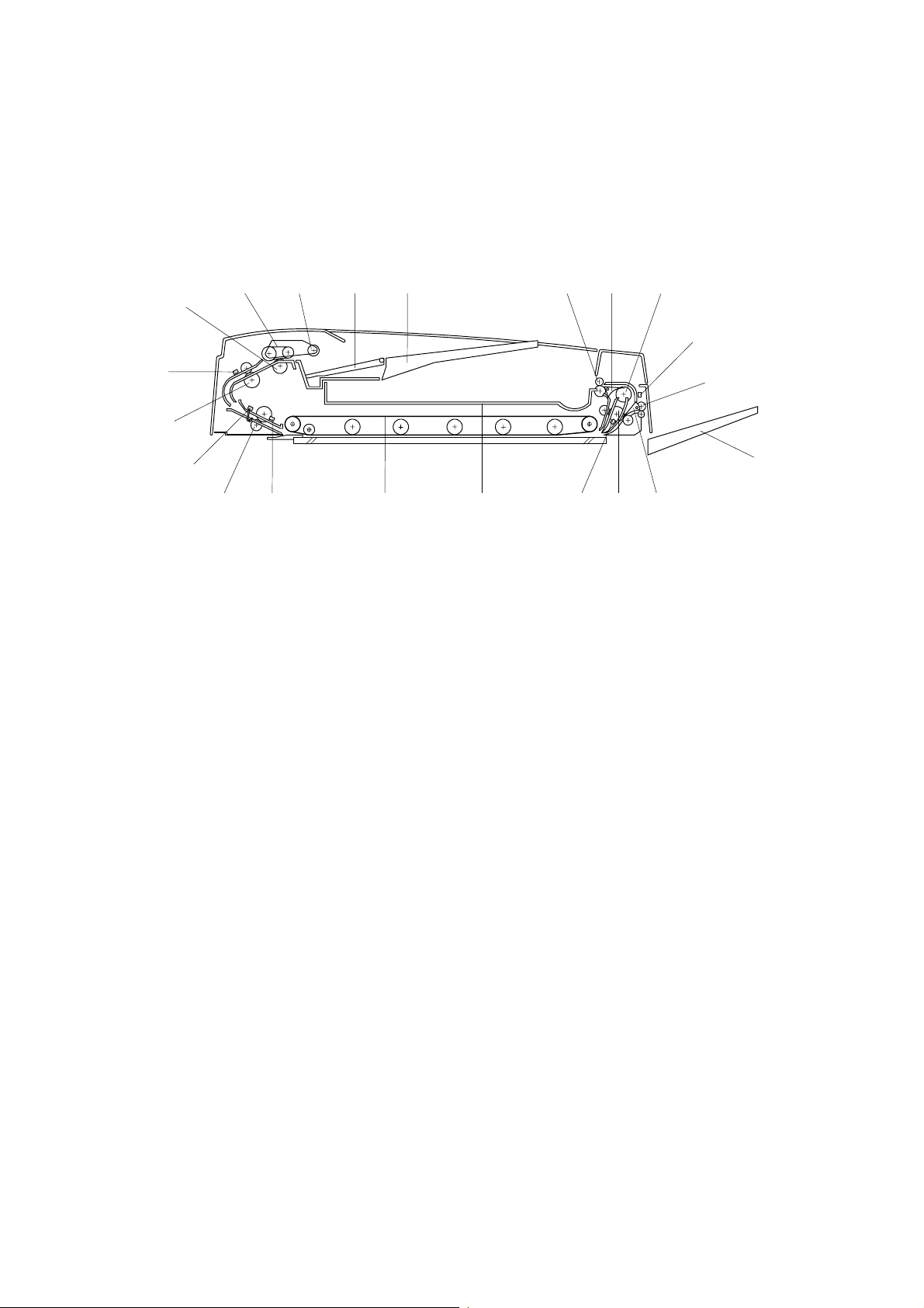
1.3.1 COPIER ENGINE
45
44
43
42
41
40
39
38
37
8
41014 15
3
2
1
7
65
9
13
1211
16
17
18
19
20
21
22
23
24
25
26
27
28
29
30
36
31
32
A293V115.WMF
333435
1-6

January 8, 2000 MECHANICAL COMPONENT LAYOUT
1. 3rd Mirror
2. 2nd Mirror
3. 1st Mirror
4. Exposure Lamps
5. LD Unit
6. Cylindrical Lens
7. Polygonal Mirror
8. Cleaning Brush
9. Quenching Lamp
10. Barrel Toroidal Lends (BTL)
11. F-theta Mirror
12. SBU
13. Charge Corona Unit
14. Shield Glass
15. Laser Synchronization Detector
31. Separation Roller
32. Tray 1 (Tandem LCT)
33. Tray 2 (550-sheet Tray)
34. Tray 3 (550-sheet Tray)
35. Pick-up Roller
36. Duplex Feed Roller
37. Duplex Transport Rollers
38. Reverse Trigger Roller
39. Inverter Unit Paper Exit Roller
40. Inverter Feed Roller
41. Pressure Roller
42. Transport Rollers
43. Paper Exit Rollers
44. Curl Correction Roller
45. Hot Roller
Overall
Information
16. Optics Cooling Fan Motor
17. Drum Cleaning Blade
18. Drum Potential Sensor
19. Drum
20. Pick-off Pawl
21. Development Unit
22. TD Sensor
23. Pick-up Roller
24. Feed Roller (By-pass Tray)
25. Separation Roller
26. Registration Rollers
27. Transfer Belt Unit
28. Relay Roller
29. Vertical Transport Rollers
30. Feed Roller
1-7
MECHANICAL COMPONENT LAYOUT January 8, 2000
1.3.2 ADF
1
21
20
19
18 17 1213141516
1. Separation Roller
2. Feed Belt
3. Pick-up Roller
4. Bottom Plate
5. Original Tray
6. Upper Tray Exit Roller
7. Inverter Gate
8. Inverter Guide Roller
9. Inverter Sensor
10. Right Tray Exit Roller
11. Right Exit Tray
7
12. Exit Gate
13. Inverter Roller
14. Exit Sensor
15. Upper Exit Tray
16. Transport Belt
17. Registration Sensor
18. Lower Transport Roller
19. Width Sensor
20. Upper T ransport Roller
21. Entrance Sensor
863425
A293V554.WMF
9
10
11
1-8

January 8, 2000 PAPER PATH
1.4 PAPER PATH
11
10
9
8
7
1
2
Overall
Information
6
5
1. ADF
2. By-pass Tray
3. Optional LCT
4. Tray 3 (550-sheet Tray)
5. Tray 2 (550-sheet Tray)
6. Tray 1 (Tandem LCT)
3
A293V107.WMF
4
7. Duplex Unit
8. Finisher
9. Inverter Unit
10. Shift Tray
11. Upper Tray
1-9
COPY PROCESS January 8, 2000
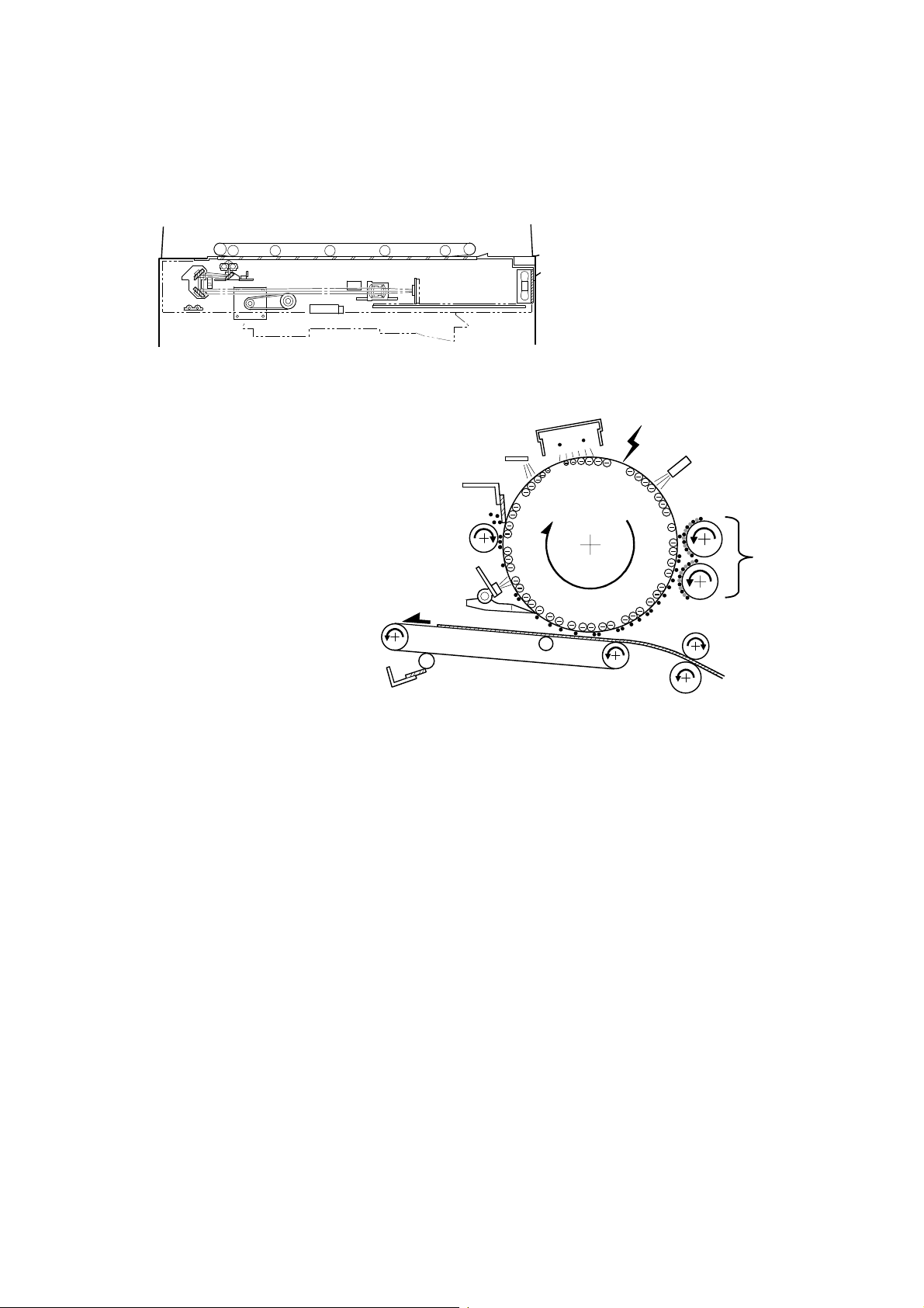
1.5 COPY PROCESS
1
A293V553.WMF
2
3
10
4
9
8
5
7
6
A293V501.WMF
1. EXPOSURE
A xenon lamp exposes the original. Light reflected from the original passes to the
CCD, where it is converted into an analog data signal. This data is converted to a
digital signal, processed, and stored in the memory. At the time of printing ,the data
is retrieved and sent to the laser diode. For multi-copy runs, the original is scanned
once only and stored to the hard disk.
2. DRUM CHARGE
An OPC (organic photoconductor) drum is used in this machine. In the dark, the
charge corona unit gives a negative charge to the drum. The grid plate ensures
that corona charge is applied uniformly. The charge remains on the surface of the
drum because the OPC layer has a high electrical resistance in the dark.
3. LASER EXPOSURE
The processed data from the scanned original is retrieved from the hard disk and
transferred to the drum by two laser beams, which form an electrostatic latent
image on the drum surface. The amount of charge remaining as a latent image on
the drum depends on the laser beam intensity, which is controlled by the BICU
board.
1-10

January 8, 2000 COPY PROCESS
4. DRUM POTENTIAL SENSOR
The drum potential sensor detects the electric potential on the drum to correct
various process control elements.
5. DEVELOPMENT
The magnetic developer br ush on the development rollers comes in contac t w i th
the latent image on the drum surface. Toner particles are electrostatically attracted
to the areas of the drum surface where the laser reduced the negative charge on
the drum.
6. IMAGE TRANSFER
Paper is fed to the area between the drum surface and the transfer belt at the
proper time to align the copy paper and the developed image on the drum. Then,
the transfer bias roller applies a high positive charge to the reverse side of the
paper through the transfer belt. This positive charge pulls the toner particles from
the drum to the paper. At the same time, the paper is electrically attracted to the
transfer belt.
7. PAPER SEPARATION
Overall
Information
Paper separates from the drum as a result of the electrical attraction between the
paper and the transfer belt. The pick-off pawls also help separate the paper from
the drum.
8. ID SENSOR
The laser forms a sensor pattern on the drum surface. The ID sensor measures the
reflectivity of the pattern. The output signal is one of the factors used for toner
supply control.
9. CLEANING
The cleaning brush removes toner remaining on the drum after image transfer and
the cleaning blade scrapes off all remaining toner.
10. QUENCHING
The light from the quenching lamp electrically neutralizes the charge on the drum
surface.
1-11
DRIVE LAYOUT January 8, 2000
1.6 DRIVE LAYOUT
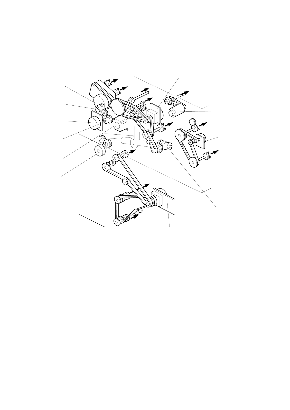
1.6.1 COPIER ENGINE
11
10
Ÿ
1
¡
š
™
2
9
8
›
ž
7
6
œ
3
•
ž
4
1. Drum Motor
2. Scanner Motor
3. Fusing/Duplex Motor
4. Toner Recycling Clutch
5. Paper Feed Motor
6. Toner Collection Motor
7. Registration Motor
8. Relay Clutch
9. By-pass Feed Motor
10. By-pass Feed Clutch
11. Development Motor
ž
5
™
Cleaning Unit
š
Scanner Unit
›
Transfer Belt Unit
œ
Fusing Unit
•
Duplex Unit
ž
Paper Feed Units
Ÿ
Toner Hopper
Development Unit
¡
Drum
A293V108.WMF
1-12

January 8, 2000 DRIVE LAYOUT
1.6.2 ADF
14
13
12
11
1
2
Overall
Information
3
4
10
5
6
9
8
7
A293V552.WMF
1. Pick-up Motor
2. Bottom Plate Motor
3. Feed-in Motor
4. Transport Motor
5. Upper Exit Roller
6. Feed-out Motor
7. Right Exit Roller
8. Transport Belt
9. Lower Transport Roller
10. Upper Transport Roller
11. Separation Roller
12. Feed Belt
13. Pick-up Roller
14. Feed-in Clutch
1-13

ELECTRICAL COMPONENT DESCRIPTION January 8, 2000
1.7 ELECTRICAL COMPONENT DESCRIPTION
Refer to the electrical component layout on the reverse side of the point-to-point
diagram for the location of the components using the symbols and index numbers.
1.7.1 COPIER ENGINE
Symbol Name Function
Motors
M1 Scanner Drives the 1st and 2nd scanners. 15
M2 Polygonal Mirror Turns the polygonal mirror. 22
LD Positioning
M3
M4 Drum Drives the drum and cleaning unit. 36
M5 Development Drives the development unit. 37
M6
M7
M8
M9
M10
M11
M12
M13
M14
M15 By-pass Feed Drives the by-pass feed rollers. 41
M16 Registration Drives the registration rollers. 40
M17
M18
M19 Optics Cooling Fan Removes heat from the optics unit. 21
M20 Drum Cooling Fan Sends the air to the drum inside. 38
M21
M22
Toner Supply Rotates the toner bottle to supply
Charge Corona Wire
Cleaner
Fusing/Duplex Drives the fusing unit, duplex unit,
Toner Collection Transports the collected toner to the
Toner Recycling
Paper Feed Drives all feed and transport rollers in
1st Tray Lift Raises and lowers the bottom plate in
2nd Tray Lift Raises the bottom plate in the 2nd
3rd Tray Lift Raises the bottom plate in the 3rd
Rear Fence Moves the paper stack in the left
Jogger Drives the jogger fences to square the
Exhaust Fan Removes heat from around the fusing
Fusing Fan
Rotates the LD unit to adjust the LD
beam pitch when a different resolution
is selected.
toner to the development unit.
Drives the charge corona wire
cleaner.
inverter unit, and paper exit rollers.
toner collection bottle.
Drives the air pump to send recycled
toner to the development unit.
the paper tray unit.
the 1st paper tray.
paper tray.
paper tray.
tandem tray to the right tandem tray.
paper stack in the duplex unit.
unit.
Removes heat from around the fusing
unit.
Index
No.
25
43
68
44
3
6
124
125
126
127
136
94
37
34
1-14

January 8, 2000 ELECTRICAL COMPONENT DESCRIPTION
Symbol Name Function
M23
Duplex Cooling Fan Removes heat from around the duplex
unit.
M24 Exit Cooling Fan Removes heat from the exit unit. 45
M25 PSU Cooling Fan Removes heat from around the PSU. 54
M26 SBU Cooling Removes the heat from around CCD. 19
Magnetic Clutches
MC1
Toner Supply Turns the toner supply roller to supply
toner to the development unit.
MC2 Toner Recycling Drives the t oner recycling unit. 1
MC3 1st Paper Feed Starts paper feed from tray 1. 100
MC4 2nd Paper Feed Starts paper feed from tray 2. 104
MC5 3rd Paper Feed Starts paper feed from tray 3. 109
MC6
By-pass Feed Starts paper feed from the by-pass
table.
MC7 Inverter Exit Clutch Drives the inverter exit roller. 88
Duplex Transport Drives the duplex transport rollers to
MC8
transport the paper to the duplex feed
rollers.
Duplex Feed
MC9
Starts paper feed out of the duplex
tray back into the machine via to the
relay rollers.
MC10
MC11
MC12
1st Vertical Relay
2nd Vertical Relay
3rd Vertical Relay Drives the 3rd vertical transport
Drives the 1st vertical transport
rollers.
Drives the 2nd vertical transport
rollers.
rollers.
MC13 Bank Relay Drives the bank relay roller. 103
MC14 Relay Drives the relay rollers. 81
Index
No.
42
Overall
Information
39
78
89
91
101
105
108
Switches
SW1
SW2
SW3
SW4
SW5
SW6
Main Power Provides power to the machine. If this
is off, there is no power supplied to
the machine.
Operation
Provides power for machine
operation. The machine still has
power if this switch is off.
Front Door Safety
Cuts the +5 V LD dc power line.
Switch 1
Front Door Safety
Switch 2
Front Door Safety
Detects if the front door is open or not,
and cuts the +24 V dc power line.
Cuts the +5 V LD dc power line.
Switch 3
Lower Front Door
Cuts the +24 V dc power line.
Safety
1-15
9
27
10
11
12
8

ELECTRICAL COMPONENT DESCRIPTION January 8, 2000
Symbol Name Function
SW7
SW8
Toner Collection
Bottle Set
Toner Overflow Detects when the toner collection
Detects if the toner collection bottle is
set or not.
bottle is full.
SW9 Paper Size Determines the size of paper in tray 2. 3
Solenoids
SOL1
SOL2
SOL3
SOL4
SOL5
SOL6
SOL7
SOL8
SOL9
Transfer Belt Lift Controls the up-down movement of
the transfer belt unit.
1st Pick-up
Controls the up-down movement of
the pick-up roller in tray 1.
2nd Pick-up Cont rols the up-down movement of
the pick-up roller in tray 2.
3rd Pick-up Controls the up-down movement of
the pick-up roller in tray 3.
By-pass Pick-up
Controls the up-down movement of
the pick-up roller for by-pass feed.
1st Separation Roller Controls the up-down movement of
the separation roller in tray 1.
2nd Separation Roller Controls the up-down movement of
the separation roller in tray 2.
3rd Separation Roller
Controls the up-down movement of
the separation roller in tray 3.
Right Tray Lock Locks the right tandem tray during
paper feed from tandem tray.
Left Tray Lock Locks the left tandem tray during
SOL10
more the paper from left tray to right
tray.
SOL11
SOL12
SOL13
Front Side Fence Opens the front side fence of right
tandem tray.
Rear Side Fence Opens the rear side fence of right
tandem tray.
Duplex Inverter Gate
Moves the junction gate to direct
copies to the duplex tray or to the
paper exit.
SOL14
SOL15
SOL16
Reverse Roller Controls the up-down movement of
the reverse trig ger roller.
Guide Plate
Opens the guide plate when a paper
misfeed occurs around this area.
Inverter Gate Opens the inverter gate during a
duplex job.
Index
No.
5
4
70
99
106
110
76
102
107
111
126
123
134
130
96
95
80
74
Sensors
S1
S2
Scanner HP Informs the CPU when the 1st and
2nd scanners are at home position.
Original Width Detects original width. This is one of
APS (Auto Page Select) sensors.
1-16
32
33
 Loading...