

Page 1
T
Model:
SP5
echnical
B
ulletin
Date:
15-Oct-98
No:
PAGE: 1/1
1
Subject:
From:
Classification:
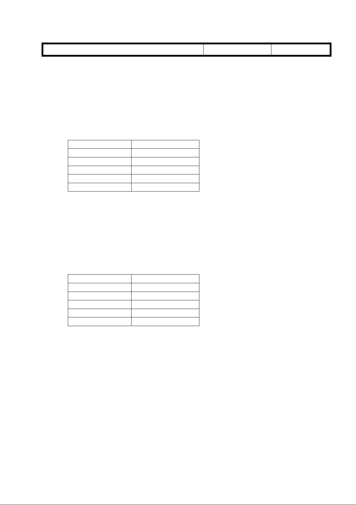
The DIP switch table for the I/O board is missing from the service manual. Please add the
following table to your manual.
DIP SW101
No. Description Function
1 Should be off. 2 Should be off. 3 SC codes display. On: SC codes are not displayed.
4 Should be off. 5 Should be off. 6 Version 1 6: Off 7: Off Japanese version
7 Version 2 6: On 7: Off 115 V version
8 Should be off. -
DIP SW of I/O Board
GTS and S Field Infomation Dept
Troubleshooting
Mechanical
Paper path
Other ( )
6: Off 7: On 220/240 V version
Part information
Electrical
Transmit/receive
Prepared by:
Action required
Service manual revision
Retrofit information
M.Tsuyuki
NOTE: When replacing the I/O board in the field, change the setting of DIP SW6 and
7 to suit the requirements for your area.
Page 2

T
Model:
SP5
echnical
B
ulletin
Date:
15-Oct-98
No:
PAGE: 1/1
2
Subject:
From:
Classification:
Please correct your A229 point to point diagram as follows
• Name of the component (position: E10)
Toner Collection Motor → PSU Coolin g Fan
• Symbol of the component (position: E10)
Toner Collection Motor (SOL9) → Tone r Collection Motor (M9)
• Signal level (position: O3)
CN209-10: +5V[5] → +24V[24]
CN209-11: [▼5] → [▼24]
Point to Point Diagram
GTS and S Field Infomation Dept
Troubleshooting
Mechanical
Paper path
Other ( )
Part information
Electrical
Transmit/receive
Prepared by:
M. Tsuyuki
Action required
Service manual revision
Retrofit information
• Connector No. (position: D7 and L3-K3)
CN266-1 → CN266-3
CN266-3 → CN266-1
CN208-A32 → CN208-A1
CN208-A31 → CN208-A2
CN208-A30 → CN208-A3
CN208-A29 → CN208-A4
CN208-A28 → CN208-A5
CN208-A27 → CN208-A6
CN208-A26 → CN208-A7
CN208-A25 → CN208-A8
CN208-A24 → CN208-A9
CN208-A23 → CN208-A10
CN208-A22 → CN208-A11
CN208-A21 → CN208-A12
CN208-A20 → CN208-A13
CN208-A19 → CN208-A14
CN208-A18 → CN208-A15
CN208-A17 → CN208-A16
Page 3

T
Model:
SP5
echnical
B
ulletin
Date:
15-Oct-98
No:
PAGE: 1/1
3
Subject:
From:
Classification:
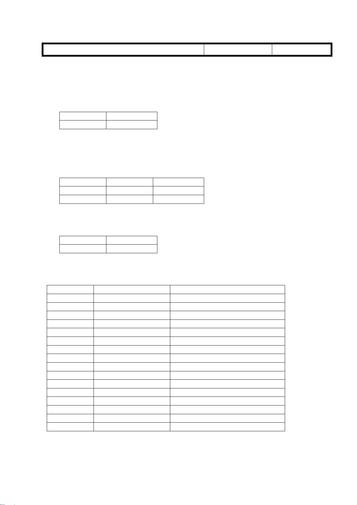
Please correct and add the following SP mode to your manual.
• Correction
SP4-008
Scanner Main Scan Magnification → Scanner Sub Scan Magnification
• Deletion
SP7-823
Because there is no SP7-303.
• Addition
SP mode
GTS and S Field Information Dept
Troubleshooting
Mechanical
Paper path
Other ( )
Part information
Electrical
Transmit/receive
Prepared by:
M. Tsuyuki
Action required
Service manual revision
Retrofit information
SP2-966 (Periodic Auto Process Control)
Function: Selects whether process control initial setting is started at periodic intervals
if the following conditions exist.
1. 24 hours or more have been passed since the last Process Control Initial
Setting.
2. The copy job is finished.
Settings: OFF(default)/ON
SP6-901 (Original No Wait Time)
SP6-901-1 (Normal Originals)
Function: Adjusts the interval between originals in normal original mode.
Settings: 500ms ∼ 700ms / 10mm/step / 620ms (default)
SP6-901-2 (Thin Originals)
Function: Adjust the intervals between originals in thin original mode.
Settings: 500ms ∼ 700ms / 10mm/step / 520ms (default)
Page 4
RICOH Technical
Bulletin
Model: SP5 Date: 31-Oct-98 No.: 4
PAGE: 1/3
Subject:
From:
Development Entrance Seal Replacement
GTS and S Field Information Dept.
Classification:
Troubleshooting
Mechanical
Paper path
Other ( )
Part information
Electrical
Transmit/receive
Prepared by:
Action required
Service manual revision
Retrofit information
A. Sasaki
This is to inform about a problem that could occur in theory.
This problem, however, will not occur at an early stage but may develop as the machine is
used over a long period of time. This problem may only occur when the photoconductor
gap (PG) is at the narrowest setting (0.65 mm) and the doctor gap is at the widest setting
(0.70 mm). This PG/DG setting does not exist in production machines as far as checked in
the factory but is still within the adjusting range.
- Problem -
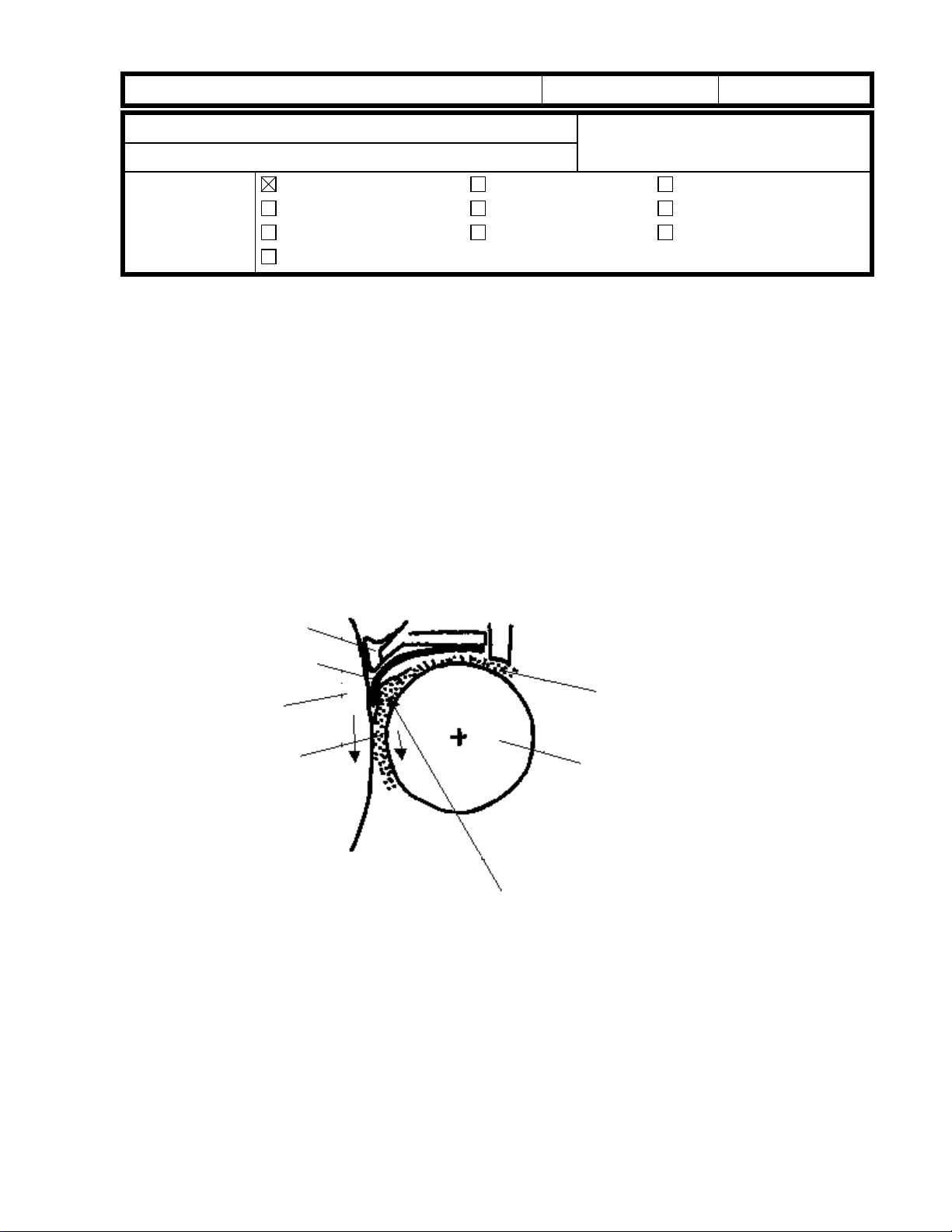
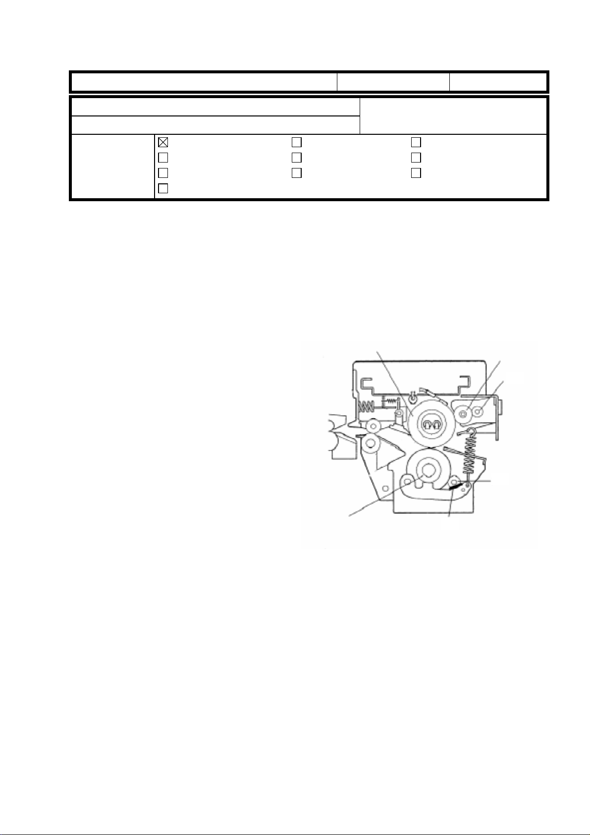
The lower seal (straight; the upper seal is a loop) of the development unit entrance seal
ass'y (P/N A2293092) may get pinched between the developer and the drum if a large
amount of developer accumulates near the photoconductor gap (PG). The seal may be
pulled out of position by the friction caused by the rotation of the drum. In the worst case,
the seal would peel off.
Upper seal
Lower seal
Drum
PG
Developer accumulation
DG
Upper development roller
- Cause -
The width of the lower seal is 18 mm, which may be too much. This problem does not
occur with the previous entrance seal ass'y (P/N A0963103) that has a width of 17mm.
- Countermeasure -
The width of the lower seal will be returned to the original 17 mm from 18 mm. Though the
17 mm lower seal may wrap up, the function of this part is not adversely affected. The part
number of the new development unit entra nce s eal ass'y will be A2293091.
Page 5
RICOH Technical
Bulletin
Model: SP5 Date: 31-Oct-98 No.: 4
- Targeted Machines -
PAGE: 2/3
Model Code Brand Destination Total Sub-
Total
SP5
A229-10 Savin/
Gestetner
A229-17 Ricoh USA,
A229-22 NRG Europe, etc. 254 70
A229-26 Infotec Europe, etc. 120 60
A229-27 Ricoh Europe, etc. 486 173
A229-29 Ricoh Asia,
USA,
Canada
Canada
Oceania
250 100
150
500 169
331
130
52
2
60
67
120
126
25 20
5
Serial Numbers
2B48060001 thru 2B48060100
2B48070001 thru 2B48070150
A7908060194 thru A7908060362
A7908070001 thru A7908070331
AS78060001 thru AS78060070
AS78070001 thru AS78070130
AS7808-0001, -0002, -0004,
-0006 thru -0008, -0012 thru -0014,
-0017, -0021 thru -0025, -0027,
-0029 thru -0031, -0034 thru -0042,
-0044, -0046 thru -0051,
-0054 thru -0059, -0061,
-0064 thru -0072, -0074
AS7809-0015, -0016
3R30780001 thru 3R30780060
3R30880001 thru 3R30880060
A7908060001 thru A7908060173
A7908070332 thru A7908070398
A7908080001 thru A7908080120
A790809-0002, -0005 thru -0010,
-0012 thru -0015, -0017 thru -0020,
-0022, -0024 thru -0027,
-0029 thru -0032, -0034 thru -0036,
-0038 thru -0041, -0044 thru -0049,
-0051 thru -0053, -0055, -0056,
-0060, -0062, -0064,
-0068 thru -0070, -0073 thru -0076,
-0078, -0080, -0083 thru -0086,
-0089, -0090, -0093, -0096, -0097,
-0099 thru -0101, -0103 thru -0107,
-0109, -0111, -0112,
-0114 thru -0116, -0118 thru -0166
A7908060174 thru A7908060193
A790808-0121, -0123 thru -0126
Page 6
RICOH Technical
Model: SP5 Date: 31-Oct-98 No.: 4
- Replacement Procedure -
Bulletin
PAGE: 3/3
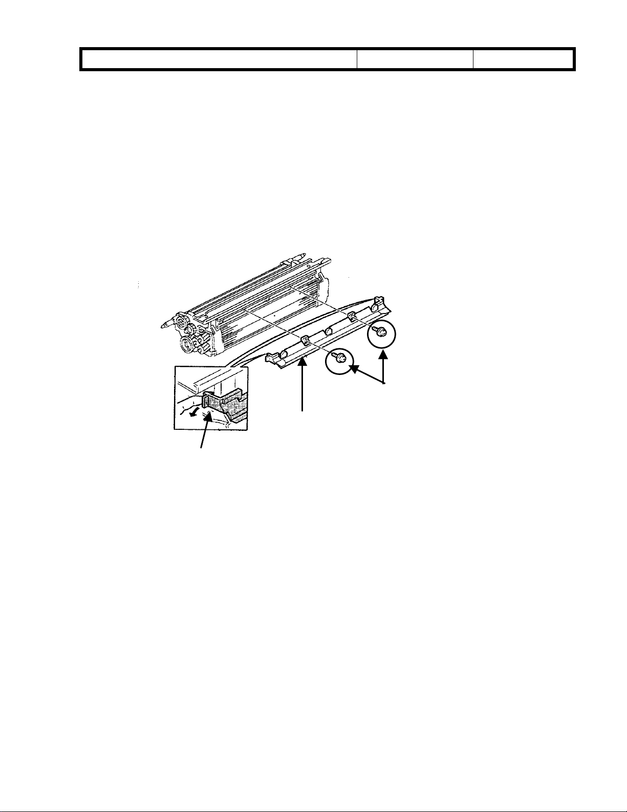
1. Remove the 2 screws
2. While pulling on the lock clip
3. Install a new entrance seal ass’y.
[A]
that secure the entrance seal.
[B]
, slip off the entrance seal ass’y
[A]
[C]
[C]
.
[B]
Page 7
T
Model: SP5 Date: 30-Nov-98 No.: 5
echnical
B
ulletin
PAGE: 1/2
Subject:
From:
Classification:
This is to inform you about troubleshooting when black spots appear on the first copy after
warming up.
Problem
Black spots may appear on the front or rear side of the first copy after warming up. The
diameter of the spots is 3 mm at most. The number of spots may be around 20 in the worst
case.
Cause
When the machine turns off and the
temperature of the fusing unit becomes
low, toner adheres less strongly to the hot
roller cleaning roller [A] and pressure
roller cleaning roller [B]. In this condition,
the toner on the hot roller cleaning roller
[A], pressure roller cleaning roller [B] or
pressure roller cleaning brush [C] may be
transferred back to the hot roller or
pressure roller and may finally adhere to
the first copy after warming up.
Black Spots on First Copy after Warming up
GTS and S Field Information Dept.
Troubleshooting
Mechanical
Paper path
Other ( )
Part information
Electrical
Transmit/receive
Prepared by:
Action required
Service manual revision
Retrofit information
[D]
A. Sasaki
[A]
[B]
This problem depends on how much
calcium carbonate comes out from the
copy paper and mixes with toner. When
more calcium carbonate is mixed with
toner, the problem becomes worse if the brush [C] is not installed.
According to tests, many brands of paper in Europe and Asia include a lot of calcium
carbonate and many of the American ones do not.
That is why the pressure roller cleaning brush [C] is installed only in the European and
Asian/Oceanian models to remove toner from the pressure roller cleaning roller [B]. (The
brush is not installed in the American model.)
[C]
Page 8
T
Model: SP5 Date: 30-Nov-98 No.: 5
Action
1. Please change the setting of SP1-103 from 0 (5.5 min) to 2 (15 min).
A longer fusing idling time can help to make the temperature of the pressure roller just
after warming up higher.
2. Please judge the necessity of the pressure roller cleaning brush by looking how the
mixture of toner and calcium carbonate adheres to the cleaning roller surface.
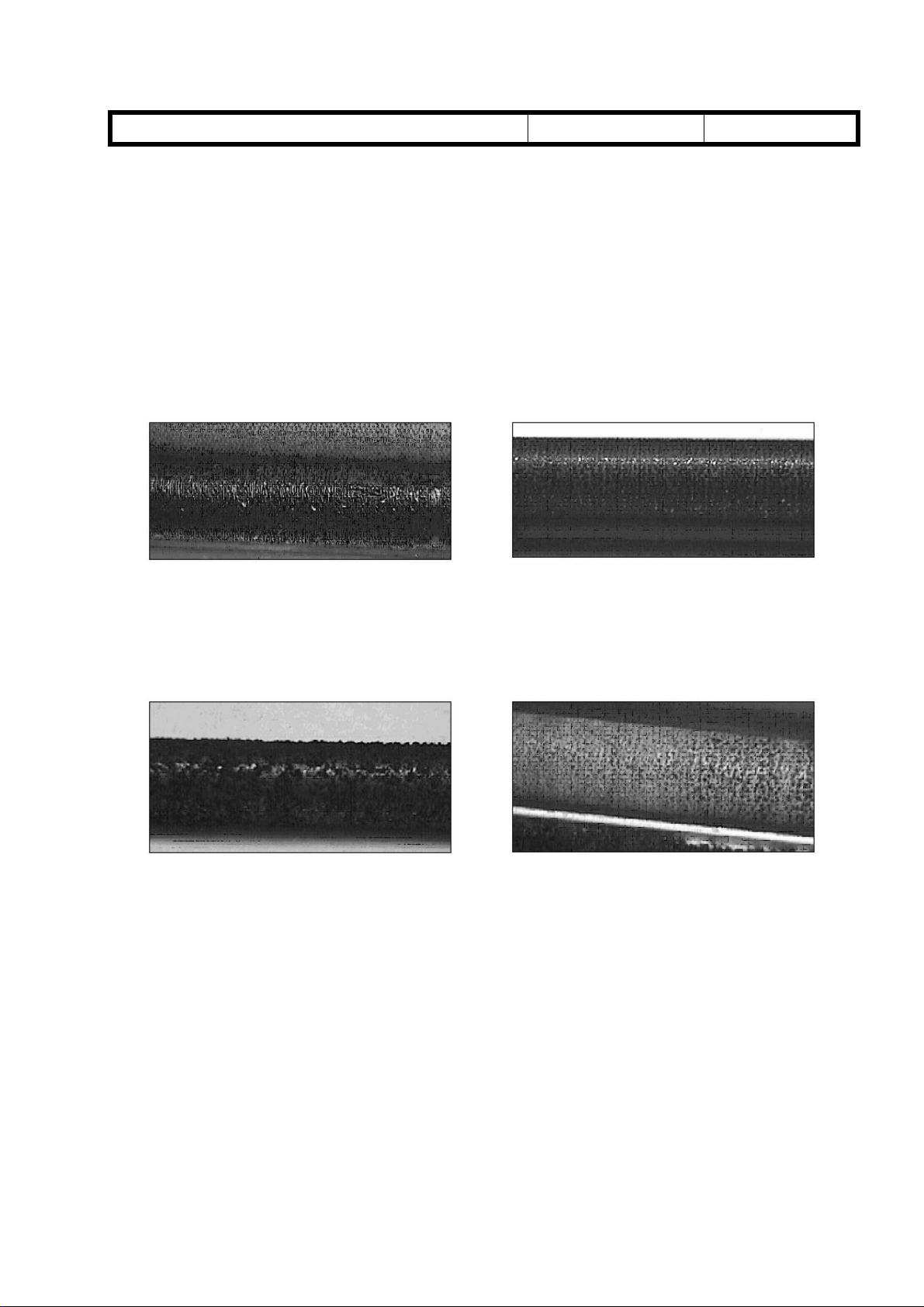
- Not necessary -
The brush is not necessary when the surface of the hot roller cleaning roller and
pressure roller cleaning roller looks shiny like the pictures below.
echnical
B
ulletin
PAGE: 2/2
Hot roller cleaning roller Pressure roller cleaning roller
- Necessary -
The brush (A229 4153) is necessary when the surface of the hot roller cleaning roller
and pressure roller cleaning roller does not look smooth, with many small balls with the
mixture of toner and calcium carbonate like in the pictures below.
Hot roller cleaning roller Pressure roller cleaning roller
This is, however, just a recommended guideline and does not match all cases in the field.
Even in one machine, the condition of the cleaning roller surface may change in any of the
following operations.
When two o r more differ ent kinds of copy paper a re used.
•
When most copies for one day are single-sided and the number of single-sided copies
•
is large, such as 4,000 copies or more.
When most copies for one day are single-sided and the image (black) area is low, such
•
as 6% or less.
Page 9
RICOH Technical
Model: SP5L Date: 31-Dec-98 No.: 6
Bulletin
PAGE: 1/1
Subject:
From:
Classification:
The following table shows the differences between the SP5 and SP5L.
No. Item SP5 SP5L
1 Copy Speed Max. 65 cpm
2 Duplex copy on
Different Points from SP5
GTSS Field Information Dept.
Troubleshooting
Mechanical
Paper path
Other (Series Model Information)
(A4/8½” x 11” sideways)
Modify the 2nd tray (by field
A5/5½” x 8½”
engineer).
(The 2nd tray will be modified
to be the same as the SP5L
tray.)
Part information
Electrical
Transmit/receive
Prepared by:
Action required
Service manual revision
Retrofit information
Max. 55 cpm
(A4/8½” x 11” sideways)
Change the fence position of
the 2nd tray (by customer).
M.Tsuyuki
Page 10

RICOH Technical
Model: SP5/SP5L Date: 31-Jan-99 No.: 7
Bulletin
PAGE: 1/1
Subject:
From:
Classification:
With analog copiers, it has not been necessary to think about confidentiality of originals
used for copying. Our copiers have recently been shifting from analog to digital in many
segments. Since most digital copiers have a hard disk that can store scanned originals for
job completion (such as collating), we must prevent the scanned originals from being
recalled from the hard disk by someone else.
The following explains how the software handles the scanned images on the hard disk.
Please explain to the customers when required.
In the copy mode, when an original is scanned, the scanned original is stored as image
on the hard disk.
The stored image on the hard disk is deleted when the job is completed (when the Start
key turns green for the next job).
Scanned Image on the Hard Disk
GTSS Field Information Dept.
Troubleshooting
Mechanical
Paper path
Other (Software explanation)
Part information
Electrical
Transmit/receive
Prepared by:
Action required
Service manual revision
Retrofit information
A. Sasaki
Page 11
T
echnical
ulletin
B
PAGE: 1/2
Model:
Subject:
From:
Classification:
Below please find the modification history from the first production run for the Main Board
up to Suffix D for the 3000-sheet Finisher (SR730).
A6975656D
SP5 (3000 Finisher)
Software Replacement Information
GTSS Field Information Dept.
Troubleshooting
Mechanical
Paper path
Other ( )
1. Occurrences of SC990
2. Defective paper exit for LG, DLT, A3 and B4 paper sizes.
3. Two staples missing when B5 size paper is stapled.
4. Stacking problems occur when paper curls during manual staple mode.
(Modification of shift tray height during manual staple mode, exit roller rotation,
speed and shift tray lowering timing)
5. When the paper curl is large during shift mode, the exit roller rolls up the paper.
(Modification of the shift tray height in the shift mode, exit roller rotation speed, and
shift tray lowering timing)
Part information
Electrical
Transmit/receive
Date:
31-Mar-99
Prepared by:
No.:
8
E. Fukuyama
Action required
Service manual revision
Retrofit information
Model Code Cut-in Serial #s
A697-15 1B58120001
A697-17 A7778110001
A697-22 AR38110281
A697-26 3R1128001
A697-55 L0328110267
A6975656C
1. When a jam occurs in the finisher, if the jam is not removed, the stap l er
motor will not shut off.
2. When the power save mode command from the main frame is received, the
machine initializes.
Model Code Cut-in Serial #s
A697-15 1B58090001
A697-17 A7778090001
A697-22 AR38090001
A697-26 3R10980001
A697-55 L0328100052
Page 12
T
echnical
ulletin
B
PAGE: 2/2
Model:
A6975656B
A6975656A
SP5 (3000 Finisher)
1. To improve the stacking in the shift tray during stapling, the following modifications
have been implemented.
a. The initial lowering timing of the shift tray is now faster and the stack start time has
been modified to allow the shift tray to return to the top position first.
b. The line velocity for the exit roller has been changed from 600 mm/s to 700 mm/s.
The paper exit pawl speed has also been changed to match this.
c. The timing for the lowering of the shift tray has been changed to 50 mm/s after the
exit sensor has detected the leading edge of the paper.
Model Code Cut-in Serial #s
A697-15 1B58070001
A697-17 A7778070001
A697-22 AR38070001
A697-26 3R10780001
A697-55 L0328100052
1. Modification to allow use of Chinese paper sizes.
2. Modification of the start of the shift tray in staple mode.
3. When an exit jam occurs in staple mode, if the door is shut before the paper is
removed,
4. Corrected the problem of an SC not being displayed even though there was a
problem with the paper exit pawl home position sensor during initialization.
5. If the diagonal staple mode was selected when there was a problem with the stapler
rotation home position sensor, an SC occurred.
Model Code Cut-in Serial #s
A697-15 1B58070001
A697-17 A7778070001
A697-22 AR38070001
A697-26 3R10780001
A697-55 L0328100052
Date:
31-Mar-99
No.:
8
Page 13

T
Model: SP5/SP5L Date: 31-Mar-99 No.: 9
echnical
B
ulletin
PAGE: 1/5
Subject:
From:
Classification:
This is to explain an adjustment to minimize dirty background at the leading edge of the
copy due to overtoning in the development unit.
Symptom
Some toner is slightly visible at the leading edge of the copy.
Solution
Please follow the flow chart of the adjustment procedure on the following pages to
minimize the symptom.
Please note that since this adjustment is to stabilize the toner amount in the development
unit at a lower level to prevent overtoning, some customers may complain about a lighter
image in black solid areas, especially at an early stage from installation and for the first
several copies every morning.
Please adjust the SP modes for the development bias to meet the required level for each
customer.
Dirty Background at Leading Edge
GTSS Field Information Dept.
Troubleshooting
Mechanical
Paper path
Other ( )
Part information
Electrical
Transmit/receive
Prepared by:
Action required
Service manual revision
Retrofit information
A. Sasaki
However, there is no problem with text area.
New Factory Settings
To minimize the dirty background, the factory settings of some SP modes have been
changed to stabilize the toner amount in the development unit at a lower level which
prevents overtoning.
Please refer to the explanation on the following page for the details.
Because of the change of the factory settings of some SP modes, black solid areas may
be lighter at installation.
This model has a toner recycling system. The toner amount in the development unit is
determined with a calculation including not only new toner but also recycled toner. At
installation, the pipe for the recycled toner is empty and it takes 1,000 to 2,000 copies for
the first recycled toner to come into the development unit.
This means that the toner amount in the development unit is less during the first 1,000 to
2,000 copies after installation and becomes higher after that.
Please adjust the SP modes for the development bias to meet the required level for each
customer.
Page 14
T
Model: SP5/SP5L Date: 31-Mar-99 No.: 9
Details of the New Factory Settings
The following settings have been changed.
1. SP2967 (Auto Image Density Adjustment)
Please note that this SP is available in the main software version 7.42.1 onward.
Old Setting New Setting
OFF ON
Function: During the period of process control after the main switch is turned on (if
the fusing unit temperature is under 100°C), the toner amount in the
development unit is checked and a small amount of toner is used if it is too
much. Then, new values of Vref and Vt are determined.
2. SP2201-2 and SP2201-4 (Development Bias Adjustment)
Old Setting New Setting
SP2201-2 390 440
SP2201-4 270 320
Function: To make the toner amount in the development unit lower and to make the
chargeability of toner higher.
echnical
B
ulletin
PAGE: 2/5
3. SP2209 (Toner Supply Rate)
Old Setting New Setting
650 850
Function: To make the amount of toner supplied for one time smaller and to make
the chargeability of toner h igher.
The cut-in serial numbers are as follows:
Model Code Serial Number Brand
A229-10 2B49410001 Savin/Gestetner
A229-17 A7909410036 Ricoh
A229-22 AS78120001 Gestetner/Nashuatec/Rex Rotary
A229-26 3R31280001 infotec
A229-27 A7908120001 Ricoh
A229-29 A7908120110 Ricoh
A229-50 From first production Savin/Gestetner
A229-54 From first production Lanier
A229-55 From first production Lanier
A229-57 From first production Ricoh
A229-59 From first production Ricoh
A229-62 From first production Gestetner/Nashuatec/Rex Rotary
A229-64 From first production Lanier
A229-65 From first production Lanier
A229-66 From first production infotec
A229-67 From first production Ricoh
Page 15
T
p
echnical
B
ulletin
Model: SP5/SP5L Date: 31-Mar-99 No.: 9
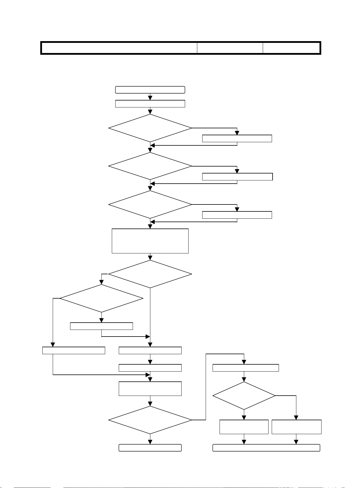
Adjustment Procedure
1. Auto Image Density Adjustment Mode
Start
Change SP2967 to ON.
PAGE: 3/5
No
Turn off the main switch to
make the fusing lamp
tem
No
Will developer
be replaced now?
Is SP2201-1 set
to 550?
Yes
Is SP2201-2 set
to 390?
Yes
Is SP2201-4 set
to 270?
Yes
erature below 100°C.
Was developer
replaced today?
Yes
No
Change it to 550.
No
Change it to 390.
No
Change it to 270.
This is done so that the machine
will perform process control.
Yes
Replace developer.
Turn on the main switch.Turn on the main switch.
Perform SP2801.
Make copies to check
copy quality.
Has the situation
improved?
Yes
End
No
Check originals.
Is the black
area large?
Yes
Change SP2209 to
750.
Go to the next page
No
Change SP2209 to
850.
Page 16

T
echnical
B
ulletin
Model: SP5/SP5L Date: 31-Mar-99 No.: 9
2. Laser Beam Pitch Adjustment
(This is to verify that the laser beam pitch is correctly adjusted.)
PAGE: 4/5
No
Start
Write down the value of
SP2109-1.
Print Pattern No. 12 of
SP2902-2. (Print A)
Do vertical lines
appear?
Yes
Change SP2109-1 in +40
steps.
Perform SP2109-3.
Print Pattern No. 12 of
SP2902-2. (Print B)
Change SP2109-1 in -80
steps.
Note: Refer to the SP number outside
the flow chart for 600 dpi.
600 dpi: SP2109-2
600 dpi: Pattern No.13 of SP2902-2
600 dpi: SP2109-2
600 dpi: SP2109-4
600 dpi: Pattern No.13 of SP2902-2
600 dpi: SP2109-2
Perform SP2109-3.
Print Pattern No. 12 of
SP2902-2. (Print C)
Compare Print B and Print C.
Is Print C better (fewer
vertical lines)?
Yes
Change SP2109-1 in -4 steps.
(This can be repeated up to
10 times.)
Perform SP2109-3.
Print Pattern No. 12 of
SP2902-2.
No
Did vertical lines
disappear?
600 dpi: SP2109-4
600 dpi: Pattern No.13 of SP2902-2
No
Change SP2109-1 in +4
steps. (This can be repeated
up to 10 times.)
600 dpi: SP2109-2
Perform SP2109-3.
600 dpi: SP2109-4
Print Pattern No. 12 of
SP2902-2.
600 dpi: No.13 of SP2902-2
Did vertical lines
disappear?
No
If not improved, go to the next page
YesYes
Page 17

T
echnical
B
ulletin
Model: SP5/SP5L Date: 31-Mar-99 No.: 9
3. Development Bias Adjustment
(This is to adjust the development bias to an appropriate level for each customer.)
Start
PAGE: 5/5
Change SP2210 to 10.
Change SP2201-4 to 270.
Change SP2201-1 to 550.
Increase SP2201-4 by 30.
Perform SP2961.
Make 10 A4/LT sideways
copies of a test chart.
Yes
Has situation
improved?
No
Increase SP2201-1 by 20.
Make 10 A4/LT sideways
copies of a test chart.
To change interval of the Vsg/Vsp check
To start adjustment from 270.
To start adjustment from 550.
Developer initia li za tio n.
Has situation
improved?
Yes
End
No
Did you repeat 4
times?
Yes
Change SP2201-4 back to
270.
Change SP2201-1 back to
550.
Change SP2209 back to 650.
End
There are other causes, such as the
drum, transfer belt, developer or toner.
No
Page 18

T
Model: SP5/SP5L Date: 31-Mar-99 No.: 10
echnical
B
ulletin
PAGE: 1/1
Subject:
From:
Classification:
This is to inform you of a possible ‘black copies’ problem.
Symptom
Black copies come out without any service codes and the machine stops with a “Please
wait” on screen.
As a second failure resulting from this problem, the SBICU board, xenon lamp flexible
board, and two lamp regulators might be damaged.
Cause
The lower insulating sheet P/N A229 1806 is not installed.
The xenon lamp flexible board P/N A229 5463 contacts the frame, the insulation
becomes worn over time and then shorts to the frame.
Optics Insul ating Sheet is Missing
GTSS Field Information Dept.
Troubleshooting
Mechanical
Paper path
Other ( )
Part information
Electrical
Transmit/receive
Prepared by:
Action required
Service manual revision
Retrofit information
A. Sasaki
Possible Units
The exact number of possible units is unknown.
Three cases have been reported so far, and all of the cases are for the units produced in
the U.S.A.
According to the information from the factories in Japan and the U.S.A., the part is
correctly installed during the present production.
It seems that this problem may happen only on a limited number of machines of the SP5
(65 ppm) produced in the U.S.A.
Action Required
Please check that the insulating sheet is installed next visit. If it is not installed, please
put insulating tape or a mylar under the flat cable of the xenon lamp flexible board
temporarily and install the insulating sheet the next time.
Page 19

RICOH Technical
Bulletin
PAGE: 1/1
Model:
Subject:
From:
Classification:
This is to inform you of a possible problem of a paper jam in Location “A” (No feed).
Symptom
A paper jam occurs just after installation. The jam location is “A”, which means a nonfeed. Once it happens, it continues.
Cause
A ring-shaped magnet in the paper feed clutch is out of position due to mis-positioning of
the glue.
Possible Units
SP5/SP5L
Paper Jams by Paper Feed Clutch (A229-27 only)
Technical Service Dept., GTS Division
Troubleshooting
Mechanical
Paper path
Other ( )
Part information
Electrical
Transmit/receive
Date:
15-Apr-99
Prepared by:
No.:
RA229011
A. Sasaki
Action required
Service manual revision
Retrofit information
The number of possible units is around six, which is about 2% out of 324 units of the
A229-27 model (Ricoh European version) with the serial numbers of A7909030-308
through -641.
Solution in the Field
1. Find the magnet around the clutch. It may be found on the frame on the other side.
2. Put super glue on the inside edges (four points [A]) as shown to fix the magnet into
the clutch.
Note: For the Paper Feed Clutch removal procedure, refer to Pages 6-70 through 6-72 in
the Service Manual.
[A]
Solution on the Production Line
To ensure the firmness of the glue, the number of glue positions has been changed from
two to four and an inspection process has been added.
[A]
Page 20

RICOH Technical
Bulletin
PAGE: 1/2
Model:
Subject:
From:
Classification:
This is to inform you of a possible problem of difficulty with the toner collection bottle
installation.
Symptom
When the toner collection bottle is installed, it might not be inserted all the way.
Please note that when removing the bottle [A], the cap [B] of the bottle hole might remain
on the nozzle [C] and the sponge seal [D] inside the cap may drop into the bottle.
SP5/SP5L
Difficulty of Toner Collection Bottle Installation
Technical Service Dept., GTS Division
Troubleshooting
Mechanical
Paper path
Other ( )
[B]
Part information
Electrical
Transmit/receive
Date:
15-Apr-99
Prepared by:
No.:
RA229012
A. Sasaki
Action required
Service manual revision
Retrofit information
[C]
[B]
[D]
[A]
Cause
The positions of the opening [E] in the bottle and the toner collection nozzle [C] are
mismatched by a few millimeters due to a production error on the bottle.
[E]
[A]
- Enlargement -
[A]
[C]
[A]
- Enlargement -
Page 21

RICOH Technical
Bulletin
PAGE: 2/2
Model:
Possible Units
A small proportion out of all units from the first mass produc ti on.
Solution in the Field
The bottle can be installed with the following procedure.
1. Hold the bottle [A] with one hand and the bottle holder [B] with the other hand.
2. Push the bottle into the machine.
SP5/SP5L
Date:
15-Apr-99
[A]
[B]
No.:
RA229012
Solution on the Production Line
The production process of the bottle has been reviewed and corrected.
Page 22

RICOH Technical
Bulletin
PAGE: 1/2
Model:
Subject:
From:
SP5/SP5L
3rd Tray Lift Motor Malfunction
GTSS Field Information Dept.
Classification:
Troubleshooting
Mechanical
Paper path
Other ( )
Part information
Electrical
Transmit/receive
Date:
15-Apr-99
Prepared by:
No.:
RA229013
A. Sasaki
Action required
Service manual revision
Retrofit information
This is to inform you of a possible 3rd tray lift motor malfunction resulting in the inability to
use the tray.
Symptom
The 3rd tray cannot be raised or lowered.
Cause
An IC on the motor control board attached to the lift motor is damaged and the lift motor
cannot be controlled.
Static electricity is a possible cause.
Possible Units
The exact number of possible units is unknow n. Reports hav e been pr ovided from
several areas.
Countermeasure
To prevent the IC from being damaged, a resistor has been added to the motor control
board.
The part number of the motor ass’y AX06-0130 has not been changed.
How to Check New Motors
There were two steps to the modification.
1st Step: A green dot has been added to the right side of the lot number label as
shown.
2nd Step: The suffix of the part number has been changed from no suffix (AX060130)
to “A” (AX060130 A) on the lot number label as shown.
P/N AX060130
Lot # 9315
Green dot
P/N AX060130 A
Lot # 9315
- 1st Step - - 2nd Step -
“A” is added.
Page 23

RICOH Technical
Bulletin
PAGE: 2/2
Model:
Cut-in Serial Number
The countermeasure has be en appli e d fro m the Apr i l 1999 pr oduction.
Service parts have already been changed to the new motors.
SP5/SP5L
Date:
15-Apr-99
No.:
RA229013
Page 24

RICOH Technical
Bulletin
PAGE: 1/2
Model:
Subject:
From:
Classification:
Please correct your service manual as follows.
SP5/SP5L
Service Manual Correction
GTSS Field Information Dept.
Troubleshooting
Mechanical
Paper path
Other ( )
Part information
Electrical
Transmit/receive
SP2201-2 (page 4-15)
Incorrect:
Factory setting: -360V
Correct:
Factory setting: -390V
NOTE:
The above setting has been changed from November or December production of
1998. See RTB 9 for details.
Date:
15-Apr-99
Prepared by:
No.:
RA229014
M. Tsuyuki
Action required
Service manual revision
Retrofit information
SP7-808
Incorrect:
Resets the following counters. Press “Start” to reset.
All counters of SP7-003
·
All counters of SP7-006
·
All counters which are listed on the counter list (UP1-19-2)
·
Correct:
Resets all counters except for the following counters. Press “Start” to reset.
All counters of SP7-003
·
All counters of SP7-006
·
All counters which are printed on the counter list. This list is printed with “Total Counter”
·
in “User Tools/Counter” menu.
Page 25

RICOH Technical
Bulletin
PAGE: 2/2
Model:
SP5/SP5L
Date:
15-Apr-99
No.:
RA229014
SC621 (Page 7-21)
Please delete SC621 from your service manual and add the following two SCs (SC621-1
and 2).
SC621-1: Communication error between SBICU board and Finisher.
-Definition- [B]
If ACK does not return within 100 ms after data has been sent from the SBICU board to
the finisher, the data is resent. However, data has been has been sent three times, and
ACK has not been reteurned.
-Possible Cause Poor connection between the SBICU board and the finisher main board
·
Finisher main board defective
·
SBICU board defective
·
SC621-2: Communication error between SBICU board and Finisher.
-Definition- [B]
During communication between the finisher main board and the SBICU board, a break
signal is sent from the finisher main board.
-Possible Cause Poor connection between the SBICU board and the finisher main board
·
Finisher main board defective
·
SBICU board defective
·
Page 26

RICOH Technical
Bulletin
PAGE: 1/4
Model:
Subject:
From:
Classification:
This bulletin will explain the recommended procedure for increasing the image density of
copies (in particular, the density of black solid areas on the left and right sides).
Symptom
1. The image density is low at installation.
2. The image density decreases during a continuous copy run.
3. Copies have lower image density on the left and right sides than in the middle.
There is no problem with text areas.
Possible Cause
SP5/SP5L
Light Copies
GTSS Field Information Dept.
Troubleshooting
Mechanical
Paper path
Other ( )
Part information
Electrical
Transmit/receive
Date:
15-Aug-99
Prepared by:
Action required
Service manual revision
Retrofit information
No.:
A. Sasaki
A229015
R
The symptoms described above are caused by a combination of the following:
1. As announced by RTB No. 9, the factory settings of some SP modes have been
changed to minimize the dirt y backgr ound.
These changes may affect the image density if originals with a high percentage of
black area and/or with black solid area at any of the sides are used.
2. The value of the toner supply ratio set in the SP mode is too low with respect to the
average percent of black area in the originals used.
3. The base toner control level in the development unit is set lower than the expected
image density level.
Action Required
Please adjust the toner supply ratio and the bias voltages for the ID sensor pattern and
for the image by following the adjustment procedure on the following pages.
Note
There might be some visible differences in half-tone areas and gray pattern areas
between the first copy and the other copies in a copy run.
This is because uncompressed data is used for the first copy and compressed data
stored in the hard disk is used for the other copies.
Page 27

RICOH Technical
Bulletin
PAGE: 2/4
Model:
Serial Numbers of Machines
The following machines have the new factory settings of some SP modes.
Please refer to RTB No. 9 for the details.
Model Code Serial Number Brand
SP5/SP5L
A229-10 2B49410001 Savin/Gestetner
A229-17 A7909410036 Ricoh
A229-22 AS78120001 Gestetner/Nashuatec/Rex Rotary
A229-26 3R31280001 Infotec
A229-27 A7908120001 Ricoh
A229-29 A7908120110 Ricoh
A229-50 From first production Savin/Gestetner
A229-54 From first production Lanier
A229-55 From first production Lanier
A229-57 From first production Ricoh
A229-59 From first production Ricoh
A229-62 From first production Gestetner/Nashuatec/Rex Rotary
A229-64 From first production Lanier
A229-65 From first production Lanier
A229-66 From first production Infotec
A229-67 From first production Ricoh
Date:
15-Aug-99
No.:
A229015
R
Page 28

RICOH Technical
A
Bulletin
PAGE: 3/4
Model:
SP5/SP5L
Adjustment Procedure
Use an A4 or LT sized sample
original from the customer.
Set SP2967 to ON.
Set changed SP settings back
to the factory settings
Change SP2201-1 to 550.
Change SP2201-4 to 270.
Change SP2209 to 650.
Start
Date:
To start adjustment from 550
To start adjustment from 270
To start adjustment from 650
15-Aug-99
No.:
A229015
R
Change SP2210 to 10.
B
Decrease SP2201-4 by 10.
Make 10 copies with the
prepared original.
Check Vsp using SP3103.
Is Vsp between
0.3 and 0.5?
Yes
Make 50 copies with the
prepared original.
Is image density
acceptable?
To change the interval of the Vsg/Vsp
check
Change to:
1st: 260, 2nd: 250, 3rd: 240
No
No
Yes
End
Has the procedure
been done 10 times?
Yes
No
Page 29

RICOH Technical
g
g
g
g
,
,
A
Bulletin
PAGE: 4/4
Model:
SP5/SP5L
Increase SP2201-1 by 20.
Make 10 copies with the
prepared ori
Check Vsp using SP3103.
Is Vsp between
0.3 and 0.5?
Yes
Make 50 copies with the
prepared ori
Is image density
acceptable?
inal.
inal.
Change to:
1st: 570
No
Yes
Date:
2nd: 590, 3rd: 610
End
15-Aug-99
Has the procedure
been done 10 times?
Yes
No
No.:
A229015
R
No
Decrease SP2209 by 50.
Make 10 copies with the
prepared ori
Check Vsp in SP3103.
Make 50 copies with the
prepared ori
inal.
Is Vsp between
0.3 and 0.5?
Yes
inal.
Is image density
acceptable?
No
Change to:
1st: 600
No
Yes
2nd: 550, 3rd: 500
No
Has the procedure
been done 10 times?
Yes
End
Has the procedure
(from B) been done
3 times?
No
Continue to change SP2201-4, SP2201-1
B
and SP2209, informing the customer that
this will increase the possibility of a dirty
background appearing.
Yes
End
Page 30

T
echnical
ulletin
B
PAGE: 1/2
Model:
Subject:
From:
Classification:
SP5 / SP5L
Exposure Lamp
Technical Service Dept., GTS Division
Troubleshooting
Mechanical
Paper path
Other ( )
Part information
Electrical
Transmit/receive
Date:
31-Aug-99
Prepared by:
No.:
RA229016
A. Sasaki
Action required
Service manual revision
Retrofit information
Symptom
The first page is blank and SC101 is displayed.
This symptom is limited to the first sheet after turning on the power. However, even on
the same machine, this problem does not occur every time the power is turned on.
Cause
The amount of light from the exposure lamp is insufficient.
If making a copy when the lamp is abnormally slow in reaching the ready status, the lamp
is not able to produce the required amount of light within the given regulated time period.
The source of the problem has been identified as defective internal components in lamps
that were produced in March 1999 (and is therefore limited to these lamps).
Action Required
The lamps produced in March were installed in machines produced in March, April and
May, 1999. If any machines have serial numbers matching those listed on the last page of
this RTB, please check the exposure lamp lot number by following the procedure
described below. If the lamps have lot numbers beginning with 39X, please replace them.
The number will be 39X, where 39 indicates a Ma rch 1999 production date and X in dicates
the actual day on which the lamp was produced. Each month is assigned a different lot
number (continuing from “37” in Jan. 1999). Therefore, January 1999 is “37”, February
=”38”, and March=”39”. This information can be found printed in black on the black lamp
cap at the rear side (and therefore may be difficult to read).
Procedure for checking the exposure lamp lot numbers (and replacement, if necessary):
1. Remove the exposure glass.
2. Slide the 1st scanner to the cutout in the rear scanner frame.
3. Read the lot number printed on the lamp cap.
4. If the first two digits of the lot number are 39, replace the exposure lamp.
Page 31

T
echnical
B
ulletin
PAGE: 2/2
Model:
< Serial Numbers of Targeted Machines >
Model
A229-22 325 AS79030153 - 253 AS79040001 - 220 A229-26 155 - 3R30490001 - 155 A229-27 1,060 A7909030765 - 1000 A7909040001 - 824 A229-50 440 2B49030001 - 240 3B89040001 - 200 A229-54 145
A229-55 398
A229-57 820 A7909031533 - 2352 - A229-59 15 A7909032353 - 2367 - A229-62 110 - B129040001 - 110 A229-64 67 L0339031341 - 400 L0469040146 - 152 A229-65 80 - L0339042019 - 98 A229-66 69 - 3U20490001 - 69 A229-67 961 A7909031001 - 1532 A9049040001 - 429 A229-17 1,964 A7909430661 - 1080 A7909440001 - 1105 A7909450001 - 440
A229-10 636 - 2B49440001 - 430 2B49450001 - 206
Code
SP5 / SP5L
Number
of Unit
7,245
March production April production May production
-
-
L0469040001 - 145 L0339041621 - 2018 -
Date:
31-Aug-99
No.:
RA229016
Page 32

RICOH Technical
Bulletin
PAGE: 1/2
Model:
Subject:
From:
Classification:
3000 Finisher for SP5/SP5L
SC621
Technical Service Dept., GTS Division
Troubleshooting
Mechanical
Paper path
Other ( )
Part information
Electrical
Transmit/receive
Date:
Prepared by:
Symptom
SC621 is generated during copy cycle.
Cause
The stapler rotation HP sensor harness shorts to the frame
The harness touches an edge
of the frame.
15-Oct-99
No.:
RA229017
A. Sasaki
Action required
Service manual revision
Retrofit information
(Enlarged)
Temporary Solution in Production
The routing of the harness has been changed as shown in the photo. This can be done in
the field.
The cut-in serial numbers are as
follows:
A697-15: 1B59060001
A697-17: A7779051901
A697-22: AR39050649
A697-26: 3R10690001
A697-55: L0329064175
The harness is routed away
from the frame.
The harness is bent.
Page 33

RICOH Technical
Bulletin
PAGE: 2/2
Model:
3000 Finisher for SP5/SP5L
Date:
15-Oct-99
No.:
RA229017
Final Solution in Production
A tape wrapping the harness has been added to the place where the harness touches the
frame and the frame has been changed to make the edge smoother.
The cut-in serial numbers are as follows:
A697-15: 1B59070001
A697-17: A7779061601
A697-22: AR39060271
A697-26: 3R10690276
A697-55: L0329074795
Page 34

RICOH Technical
Bulletin
PAGE: 1/1
Model:
Subject:
From:
Classification:
Please correct your service manual as follows:
Page 7-19
- Incorrect -
SC546: Fusing ready temperature malfunction
- Correct -
SC546-01: Fusing temperature instability 1
- Definition – [A]
SP5/SP5L
Service Code SC546
GTSS Field Information Dept.
Troubleshooting
Mechanical
Paper path
Other ( )
The following condition occurs twice consecutively: The fusing temperature goes up or
down by more than 20°C within 1 second.
Part information
Electrical
Transmit/receive
Date:
15-Jan-00
Prepared by:
Action required
Service manual revision
Retrofit information
No.:
A. Sasaki
RA229018
- Possible causes –
Poor thermistor connection
·
Poor fusing unit connector connection
·
SC546-02: Fusing temperature instability 2
- Definition – [A]
The following condition occurs 3 times within 60 seconds: The fusing temperature goes
up or down by more than 20°C within 1 second
- Possible causes –
Poor thermistor connection
·
Poor fusing unit connector connection
·
Page 35

T
echnical
B
ulletin
PAGE: 1/1
Model:
Subject:
From:
Classification:
Please add the following information to your service manual:
Page 2-131
The drum heater, the optics anti-condensation heater, and the two tray heaters, which turn
on when the machine is off, are included in the machine but the connectors, CN102 and
CN103, on the PSU are not connected.
Please connect the connectors when necessary.
SP5/SP5L
Heaters
Technical Services Dept., GTS Division
Troubleshooting
Mechanical
Paper path
Other ( )
Part information
Electrical
Transmit/receive
Date:
31-Jan-00
Prepared by:
No.:
RA229019
A. Sasaki
Action required
Service manual revision
Retrofit information
Page 36

!"#$% T
echnical Bulletin
PAGE: 1/1
Model
Subject:
From:
: SP5/SP5L
Software Update for Mail Box CS360
Technical Services Dept., GTS Division
Classification:
Troubleshooting
Mechanical
Paper path
Other ( )
Part information
Electrical
Transmit/receive
Date:
14-Apr-00
Prepared by:
No.:
RA229020
A. Sasaki
Action required
Service manual revision
Retrofit information
Background
The mail box (CS360) is currently an optional item for the SP5/SP5L (A229) and NAD
30S/30/40 (A230/A231/A232), and can also be installed on the Mojito (A292/A293).
The A292/A293 has a faster process speed than the A229 and A230/A231/A232. New
software (G909 0339 A) is necessary to allow the CS360 to work smoothly on the Mojito.
Interchangeability between Main Frame and CS360
The new software can also handle the A229 and A230/A231/A232 perfectly.
Old CS360 Software New CS360 Software
NAD 30S/30/40 (A230/A231/A232) Workable Workable
SP5/SP5L (A229) Workable Workable
Mojito (A292/A293) Not workable Workable
Cut-in Serial Numbers
Destination Cut-in Serial Number
G909-15 (Savin, Gestetner) 2B20030001
G909-17 (Ricoh) G8170020001
G909-22 (NRG) BO00020001
G909-26 (Infotec) From next production
G909-55 (Lanier) L0340020001
Page 37

!"#$% T
echnical Bulletin
PAGE: 1/8
Model:
Subject:
From:
SP5/SP5L
SBICU Firmware Modificaiton Histories
Technical Service Dept., GTS Division
Classification:
Troubleshooting
Mechanical
Paper path
Other ( )
Part information
Electrical
Transmit/receive
Date:
26-Apr-00
Prepared by:
No.:
A. Sasaki
Action required
Service manual revision
Retrofit information
As there are five types of firmware, use the appropriate one for each customer.
Destination Part Number Product Codes/Languages
America A229 7540
Eu1_Asia A229 7560
Eu2 A229 7565
Eu3 A229 7566
Eu3 (Lanier) A229 7567
A229-10, -17, -50, -54, -55, -57
US English, French, Spanish
A229-22, -26, -27, -29, -59, -62, -64, -65, -66, -67, -69
English, French, Spanish, German, Italian, Dutch
A229-22, -26, -27, -62, -64, -65, -66, -67
English, German, Swedish, Norwegian, Danish, Finnish
A229-22, -26, -27, -62, -66, -67
English, German, Portuguese, Polish, Hungarian, Czech
A229-64, -65
English, German, Portuguese, Polish, Czech
RA229021
Firmware Version and Part Number Suffix for Each Destination
Destination America Eu1_Asia Eu2 Eu3 Eu3 (Lanier)
Part Number A229 7540 A229 7560 A229 7565 A229 7566 A229 7567
Version/Suffix
9.29 G G C A A
9.30 H H D B B
9.33 J J E C C
9.33.1 K K F D D
9.34 L L G E E
9.36 M M H F F
9.37 N N J G G
Page 38

!"#$% T
echnical Bulletin
PAGE: 2/8
Model:
SP5/SP5L
Date:
26-Apr-00
No.:
RA229021
Version 9.29
Destination America Eu1_Asia Eu2 Eu3 Eu3 (Lanier)
Part Number A229 7540 G A229 7560 G A229 7565 C A229 7566 A A229 7567 A
1. New BAM Standards
To meet the new BAM standards, the wattage when the main switch is off has been
decreased.
2. Specific Chinese Paper Sizes, 8K and 16K
To make the Auto Paper Selection (APS) function available for the specific Chinese paper
sizes, 8K and 16K, the following service programs have been changed:
SP5-131 (Paper Size Type Selection)
Setting No. 3 has been added to indicate buttons for the 8K and 16K paper sizes for Tray 2 on
the LCD when the screen of the Paper Size Setting menu in the User Tools is opened.
Old New
0: JP (Japan) 0: JP (Japan)
1: NA (North America) 1: NA (North America)
2: EU (Europe) 2: EU (Europe)
3: CH (China)
SP4-303 (APS A5/HLT Size Original Detection)
Setting Nos. 2 and 3 have been added to detect 8K and 16K as standard original sizes in
platen mode.
Old New
0: Not detected 0: Not detected
1: A5 lengthwise / 5½“ x 8½“ 1: A5 lengthwise / 5½“ x 8½“
2: Not detected (for 8K/16K)
3: A5 lengthwise (for 8K/16K)
Note: The difference between Settings “2” and “3” is only how the machine handles original
size when none of the original size sensors can detect the size. (Refer to the table
below)
In case of "2", "Cannot detect original size" is displayed.
In case of "3", the original size is handled as A5 lengthwise.
Original Size
Length
sensor2
O O O O O A3L A3L 8KL 8KL
O O O O X B4L B4L 8KL 8KL
O O O X X 8½"x13"L 8½"x13"L 8½"x13"L 8½"x13"L
X O O X X A4L A4L 16KL 16KL
X O X X X B5L B5L 16KL 16KL
X X O O O A4 A4 16K 16K
X X O O X B5 B5 16K 16K
XXOXXA5A5A5A5
X X X X X A5L --- A5L ---
Length
sensor1
Width
sensor1
Width
sensor2
Width
sensor3
SP4303
Setting 0
SP4303
Setting 1
SP4303
Setting 2
SP4303
Setting 3
Page 39

!"#$% T
echnical Bulletin
PAGE: 3/8
Model:
3. 14 Languages on the LCD
SP5/SP5L
How to Make the APS Function Valid for the ADF Mode
1. Select “3” with SP5-131.
2. Print out all SMC data lists (Copy Management Report) using SP5990-1.
This is necessary to re-input necessary data after SP5-801 is done.
3. Set DIP switches 6 and 7 on the I/O board to the "ON" positions.
4. Perform SP5-801 (Memory All Clear).
These two steps are necessary to make Setting 3 of SP5-131 valid.
5. Set the paper size actuator of Tray 2 to the "*" (asterisk) position.
6. Select 8K or 16K with the User Tools.
(System Settings - Paper Size Setting - Tray 2: Paper Size Setting)
How to Make APS Function Valid for the Platen Mode
1. Select "2" or "3" with SP4-303.
2. Set the paper size actuator of Tray 2 to the "*" (asterisk) position.
3. Select 8K or 16K with the User Tools.
(System Settings - Paper Size Setting - Tray 2: Paper Size Setting)
14 languages are available on the LCD by installing the appropriate SBICU firmware.
Date:
26-Apr-00
No.:
RA229021
Version 9.30
Destination America Eu1_Asia Eu2 Eu3 Eu3 (Lanier)
Part Number A229 7540 H A229 7560 H A229 7565 D A229 7566 B A229 7567 B
1. Printer Function
The printer functions have been added to use the SP5/SP5L (A229) as a printer.
2. Copy Count in Connect Copy Configuration
The copy counter displayed on the main unit as the total number of copies made on both units
becomes different from the actual number when the count of the sub-unit is 256 or larger.
The error has been corrected.
Version 9.33
Destination America Eu1_Asia Eu2 Eu3 Eu3 (Lanier)
Part Number A229 7540 J A229 7560 J A229 7565 E A229 7566 C A229 7567 C
1. Copy Management Report on LT (11” x 8-1/2”) paper
A small part of the Copy Management Report (SP5990) is missing when it is printed out on LT
paper.
The error has been corrected.
Page 40

!"#$% T
echnical Bulletin
PAGE: 4/8
Model:
2. Counting Error for the User Code Counter in Energy Saver Mode
SP5/SP5L
When the machine goes into Energy Saver mode and comes back to the Copy mode, the
dialog box asking for a user code is not displayed on the operation panel. This means that
copies can be made without any user code, and this can be continued till the next time that the
dialog box asking for a user code appears. The copies made in this period are not allocated to
any of the user codes set.
The error has been corrected to show the dialog box on the operation panel when the Energy
Saver mode is released.
Date:
26-Apr-00
No.:
RA229021
Version 9.33.1
Destination America Eu1_Asia Eu2 Eu3 Eu3 (Lanier)
Part Number A229 7540 K A229 7560 K A229 7565 F A229 7566 D A229 7567 D
1. Counting Error for the User Code Counter in Energy Saver Mode
This error has been corrected in Version 9.33 but there is still a small error.
The dialog box asking for a user code is not displayed on the operation panel if the Energy
Saver mode is released before the time set as the Auto Reset Timer in the Copy Features of
the User Tools comes, and copies can be made without inputting a user code.
In this case, the copies made are allocated to the user code that was used for the previous
job.
The error has been corrected to show the dialog box on the operation panel when the Energy
Saver mode is released.
2. Slower Copying Speed for Duplex Copies in Document Server Mode
The copying speed of duplex copies in Document Server mode is slower than that in Copy
mode by about 30%.
The copying speed in Document Server mode has been increased to be the same as in Copy
mode.
Version 9.34
Destination America Eu1_Asia Eu2 Eu3 Eu3 (Lanier)
Part Number A229 7540 L A229 7560 L A229 7565 G A229 7566 E A229 7567 E
1. Display Error for the Key Counter in Energy Saver Mode
The dialog box asking for insertion of a key counter is mistakenly displayed even if a key
counter is still inserted when the Energy Saver mode is released.
The dialog box disappears if a key counter is inserted.
The error has been corrected not to show the dialog box on the operation panel when the
Energy Saver mode is released, if a key counter is inserted.
Page 41

!"#$% T
echnical Bulletin
PAGE: 5/8
Model:
2. Improvement for SC365 (Image Storage Address Error)
3. Improvement for Paper Jams in the Fusing Unit
4. Maximum Number Input for Paper Designate / Chapter Functions
SP5/SP5L
SC365 may sometimes be indicated when there is a timing error for passing image data into
memory during printing process.
The timing has been improved, so that the number of SC365 errors indicated unnecessarily
can be decreased.
If an accordion-shaped paper jam occurs in the fusing unit, none of the sensors in the machine
may detect it. If a customer does not notice the jammed paper at this time and closes the front
door without removing the paper, the machine enters the Ready condition again.
If the next job starts in this situation, the jammed paper in the fusing unit may wrap around the
fusing roller and the copies of the next job will not be completely fused.
To guide the customer to remove jammed paper which does not reach the Fusing Exit Sensor
as Index No. 107 of the Electrical Component Layout (or the Exit Unit Entrance Sensor as Jam
No. SP7504-15 on the Logging Data Sheet), the software has been modified, so that the jam
condition is not reset without pulling out and pushing in the fusing unit. This modification is
available only when DIP switch No. 4 on the I/O board is ON.
The maximum number which can be input for page numbers of the Designate / Chapter
papers has been changed from 99 to 250.
Date:
26-Apr-00
No.:
RA229021
Version 9.36
Destination America Eu1_Asia Eu2 Eu3 Eu3 (Lanier)
Part Number A229 7540 M A229 7560 M A229 7565 H A229 7566 F A229 7567 F
1. The Copier Stops when copying the 64th Copy
This symptom rarely occurs.
On the SP5/SP5L with any of the following conditions:
a) Output Priority in the System Settings of the User Tools is set to “Printer”.
b) Output Priority in the System Settings of the User Tools is set to “Display” and while the
screen of the Printer function is displayed on the LCD.
While copying with the following settings, the machine may stop when the total number of
copies made becomes 256, 512, 1024, etc. and does not start copying again even if the Start
key is pressed.
a) The total number of copies in a copy job is 256 or more.
b) Any of the Staple modes is selected
c) When the last sheet of a stapled set becomes 256, 512, 1024, etc.
2. Malfunction with Originals with Mixed Sizes in Duplex Mode
When several sheets of smaller-sized originals (e.g. A4 sideways) and one sheet of a largersized original (e.g. A3) are copied in the Mixed Original and 1-to-2 duplex modes, an original
jam may occur or the machine remains in copy mode without actual copying taking place.
Page 42

!"#$% T
echnical Bulletin
PAGE: 6/8
Model:
3. Malfunction when Printing 600 dpi Files and 400 dpi Files in Document Server Mode
4. Malfunction with SP2506 (Cleaning Interval – Multiple Copy)
5. Some Parts of the Image Missing in Rotate Sort When Printing from the Document
6. Display Panel Mistake in Danish
SP5/SP5L
When the files transmitted from PCs (600 dpi) and the scanned files (400 dpi) stored in the
Document Server are printed at the same time in duplex mode, a copy jam may occur or the
machine remains in copy mode without actual copying taking place.
When SP2506 functions during a copy job, the machine remains in copy mode without actual
copying taking place.
The error has been corrected.
Server
When files in the Document Server are printed in the Rotate Sort and Duplex modes on the
SP5/SP5L with A4/LT sideways in the trays, the image on the back side of the even-numbered
copies is not rotated.
This symptom occurs only when the Auto Tray Switching function of the System Settings in the
User Tools is set to “No”.
The “Finisher – Shift Tray” and “Finisher – Proof Tray” buttons in the User Tools (System
Settings – Basic Page 2 – Copy / Document Server / Printer: Output Tray) are displayed in the
opposite positions.
Date:
26-Apr-00
No.:
RA229021
7. Prepaid Card System
Please note that this modification has been made just to support the Prepaid Card
Systems presently working in the field, and there is no guarantee that all of the Prepaid
Card Systems can work with this software.
Symptom
A copy jam occurs when the credit on a prepaid card becomes zero.
How to Set
• Select “3. Prepaid Card” with SP5113.
• Select “Copy” in the User Tools. (System Settings – Count Manager – Set Key Card)
Note
The copy speed in the duplex mode is decreased by 40% because the interleaf feeding
method cannot be used.
The printing speed decrease in duplex mode can be bypassed by setting DIPSW No.1 on the
I/O board to ON, but some copies can be made without any credits on the card.
8. Key Operator Code
Modification
The valid area of the Key Operator Code can be extended by setting DIPSW No.5 on the I/O
board to ON, so that the Key Operator Code has to be entered when opening System
Settings, Copy Features, Printer Features and Document Server Setting in the User Tools.
Page 43

!"#$% T
echnical Bulletin
PAGE: 7/8
Model:
SP5/SP5L
Date:
26-Apr-00
No.:
RA229021
Version 9.37
Destination America Eu1_Asia Eu2 Eu3 Eu3 (Lanier)
Part Number A229 7540 N A229 7560 N A229 7565 J A229 7566 G A229 7567 G
1. Paper Jam in the Sub-unit in Connect Copy mode
When making copies in duplex, staple and connect copy modes, a paper jam may occur in the
sub-unit.
2. Black Image in the Trailing Edge Area of Copies from the By-pass Tray
The by-pass tray becomes empty during copying and if the size of the paper newly placed is
changed, a black image may appear at the trailing edge area of copies.
3. Request from the Italian Post Office
To meet a request from the Italian Post Office, the program related to the total counter has
been modified.
Version 9.39
Destination America Eu1_Asia Eu2 Eu3 Eu3 (Lanier)
Part Number A229 7540 P A229 7560 P A229 7565 K A229 7566 H A229 7567 H
1. Paper Rotation by 180 Degrees
When a pre-printed paper such as letterhead paper is used as copy paper in the copy mode,
there is a case that the image on copies is rotated by 180 degrees against the letterhead. It
depends on whether the staple and/or punch modes are selected. So, customers need to be
careful in which way pre-printed paper types are loaded for each copy job.
Improvement
By turning on DIP switch No. 8 on the I/O board, the image is always rotated by 180 degrees.
So, customers can load such paper always in one way.
Note
This improvement is not valid for by-pass feed.
2. SC302-1
Symptom
SC302-1 may be displayed during the process control initialization.
Cause
It is not a real problem but the conditions to detect the SC are too strict.
Solution
The conditions have been changed not to detect SC302-1 mistakenly.
Page 44

!"#$% T
echnical Bulletin
PAGE: 8/8
Model:
3. SC302, SC391 and SC401
4. SC990 when Initial Mode in User Tools is Set to “Program No. 10”
5. Drum Reverse Rotation
SP5/SP5L
Symptom
When SC302 is detected, SC391 and SC401 usually follow.
Cause
These SC’s are all related to high voltages. When one of them is detected, the supply of all
high voltages is immediately stopped. So, not only the original SC number is displayed but
also the others follow.
Solution
Only the original SC number is detected.
Symptom
SC990 may be displayed when the Modes Clear key is pressed.
This symptom only occurs when the Initial Mode in the Copy Features of the User Tools is set
to “Program No. 10” and two machines are connected in tandem.
Solution
The software bug is corrected.
The condition of the drum reverse rotation has been changed to minimize load of the related
parts. (See service manual Page 2-58)
Old
At the end of every copy job.
New
Only when the following two conditions are fulfilled:
• When a copy job is finished.
• When the total time of drum rotation has reached four minutes since the last rotation.
Date:
26-Apr-00
No.:
RA229021
6. Charge Corona Cleaner Movement
The condition for detecting an error in the charge corona cleaner movement has been
changed not to count a SC up too early even when the movement is not so smooth.
Page 45

echnical Bulletin
T
PAGE: 1/2
Model:
Subject:
From:
SP5/SP5L
Light Copies (No.2)
Technical Services Dept., GTS Division
Classification:
Troubleshooting
Mechanical
Paper path
Oth e r ( )
Part information
Electrical
Transmit/receive
Date:
28-Aug-00
Prepared by:
No.:
RA229022
A. Sasaki
Action required
Service manual revision
Retrofit information
This bulletin will explain the recommended adjustment procedure for when the image
density on the whole page becomes lighter and lighter day by day because of low monthly
copy volume.
This bulletin is different from RTB #15, which is for lower image density in solid black
areas.
SYMPTOM
The image density on the whole page of the copies becomes slightly lighter and lighter day
by day.
POSSIBLE CAUSE
The monthly copy volume is very low.
When the co py volume is low, the mixing time in the development unit is shor t. This
causes the chargeability of the tone r to become lower. In this condition, the TD sensor
tends to detect that the toner amount in the development unit is more than the actual
amount, so not enough new toner is supplied.
During the process control initialization the next morning, Vcont is determined at a lower
value than the previous day because of the reduced toner amount in the development unit.
ADJUSTMENT PROCEDURE
Before starting the adjustment, do the following:
• Calculate the average monthly copy volume.
• Check the value of SP2906 (Vcont Manual Setting).
• Check the setting of SP2967 (Auto Image Density Adjustment)
• Print out the SMC sheets (SP5990-1)
• Make several copies as samples and check the image density.
Page 46

echnical Bulletin
g
p
T
PAGE: 2/2
Model:
SP5/SP5L
Start
Is the image density on
a whole page low?
Yes
Is the average monthly
copy volume lower than
20K copies?
Yes
Set SP2967 to OFF.
Change SP2201-1 to 550.
Change SP2201-4 to 270.
Date:
No
No
28-Aug-00
End
End
No.:
RA229022
Change SP2209 to 650.
Change SP2210 to 10.
Change SP2906 to 9.0.
Is new developer
available?
Yes
Change developer.
Do SP2801 (TD sensor initial setting).
Do SP2962 (Auto process control).
Make several copies and
check image density.
To change interval of Vsg/Vsp check
Vcont settin
No
Do SP2207 (Forced toner
supply) 3 times.
Do not use original with a high
ercentage of black area.
Is image density
acceptable?
Yes
End
No
To meet customer’s taste,
change SP2201-1, SP2201-4
and SP2209 appropriately.
End
Page 47

echnical Bulletin
T
PAGE: 1/1
Model:
Subject:
From:
SP5
Toner Pump Lock
Technical Services Dept., GTS Division
Classification:
Troubleshooting
Mechanical
Paper path
Other ( )
Part information
Electrical
Transmit/receive
Date:
22-Aug-01
Prepared by:
No.:
RA229023
M.Matsuda
Action required
Service manual revision
Retrofit information
SYMPTOM
The toner recycling pump locks.
CAUSE
The quality of recycled toner gradually decreases, eventually hardening and clumping to
the point where the Toner Recycling Pump is no longer able to effectively circulate it.
Note: In particular, this occurs when the surrounding temperature of the machine is high,
such as in relatively high-temperature environments or when there is a minimum amount
of free space around the machine.
SOLUTION
Replace the Pulley and Timing Belt with the modified parts listed below, which will
effectively increase the drive power of the pump from 225 rpm to 400 rpm.
Old Parts Number New Parts Number Description Int Page and Index No
AB030458 AB030720 Pulley 121 - 28
As a set X/O
AA043415 AA043573 Timing Belt
Note: Be sure to replace these 2 parts as a set.
123 - 24
 Loading...