

Page 1
echnical Bulletin
T
PAGE: 1/3
Model:
Subject:
From:
Dolphin
Service Manual
Technical Services Dept., GTS Division
Classification:
Troubleshooting
Mechanical
Paper path
Other ( )
Part information
Electrical
Transmit/receive
Date:
23-Aug-01
Prepared by:
No.:
RB010001
F. Noguchi
Action required
Service manual revision
Retrofit information
The sentences in italics show recent corrections to the Service Manual. Please correct
your manuals accordingly.
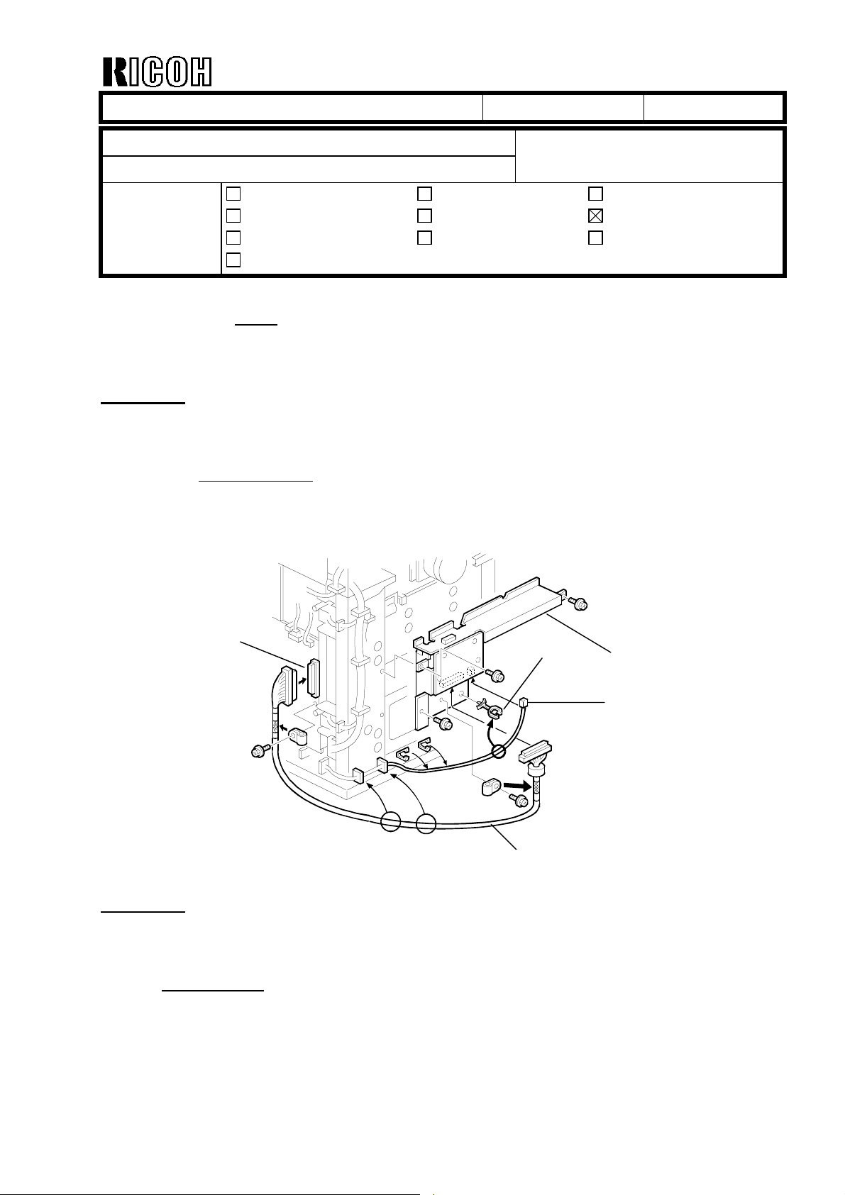
Page 1-25 1.7.2 INSTALLATION PROCEDURE
Corrected: Step 5 and illustration
5. Install the wire saddle [H] and connect the DC harness [I] from the main frame to the
I/F board.
[G]
Page 3-11 3.5.1 DRUM AND DEVELOPMENT UNIT
Corrected: Step [C]
[C]: Toner hopper cover (! x 2)
[F]
[H]
[E]
[I]
Page 2
echnical Bulletin
T
PAGE: 2/3
Model:
Dolphin
Date:
23-Aug-01
Page 5-21 5.9 SP (SERVICE PROGRAM) MODE TABLE
Deleted: The following SP modes.
5501: PM Alarm Level
5504: JAM Alarm Level
5505: Error Alarm Interval
5507: Paper Supply Call Level
5590: Auto Call Level
5816: CSS Function
5821: CSS PI Device Code
Corrected: SP mode descriptions.
Mode Number/Name Function / [Setting]
1103 Fusing Idling Selects the fusing idling time.
[0 ~ 3/ 0 / 1 min. step]
0: No idling
1: 1 minutes
2: 3 minutes
3: 5 minutes
5958 15 m Setting Enables or disables the optional special order firmware
designed for measuring 15 meter paper lengths.
[0 ~ 1 / 0 / 1 step]
0: Enable
1: Disable
No.:
RB010001
Page 6-30 6.6.3 DEVELOPMENT BIAS
Corrected: “Making ID Sensor Patterns” paragraph
Making ID Sensor Patterns
The machine makes two different ID sensor patterns, one for Low Duty Mode and one
for High Duty Mode. The mode is determined by SP 2201 004.
If the average copy volume is high (2.5 km/month or more), this SP should be
switched to High Duty Mode to prevent toner scattering.
However, if the machine is in High Duty Mode and the average copy volume becomes
low again, the image density may decrease. If this happens, switch back to Low Duty
Mode.
The ID sensor pattern development bias voltages for high and low duty modes can be
adjusted with SP 2201 002 and 003, as shown in the following table.
Page 3
echnical Bulletin
T
PAGE: 3/3
Model:
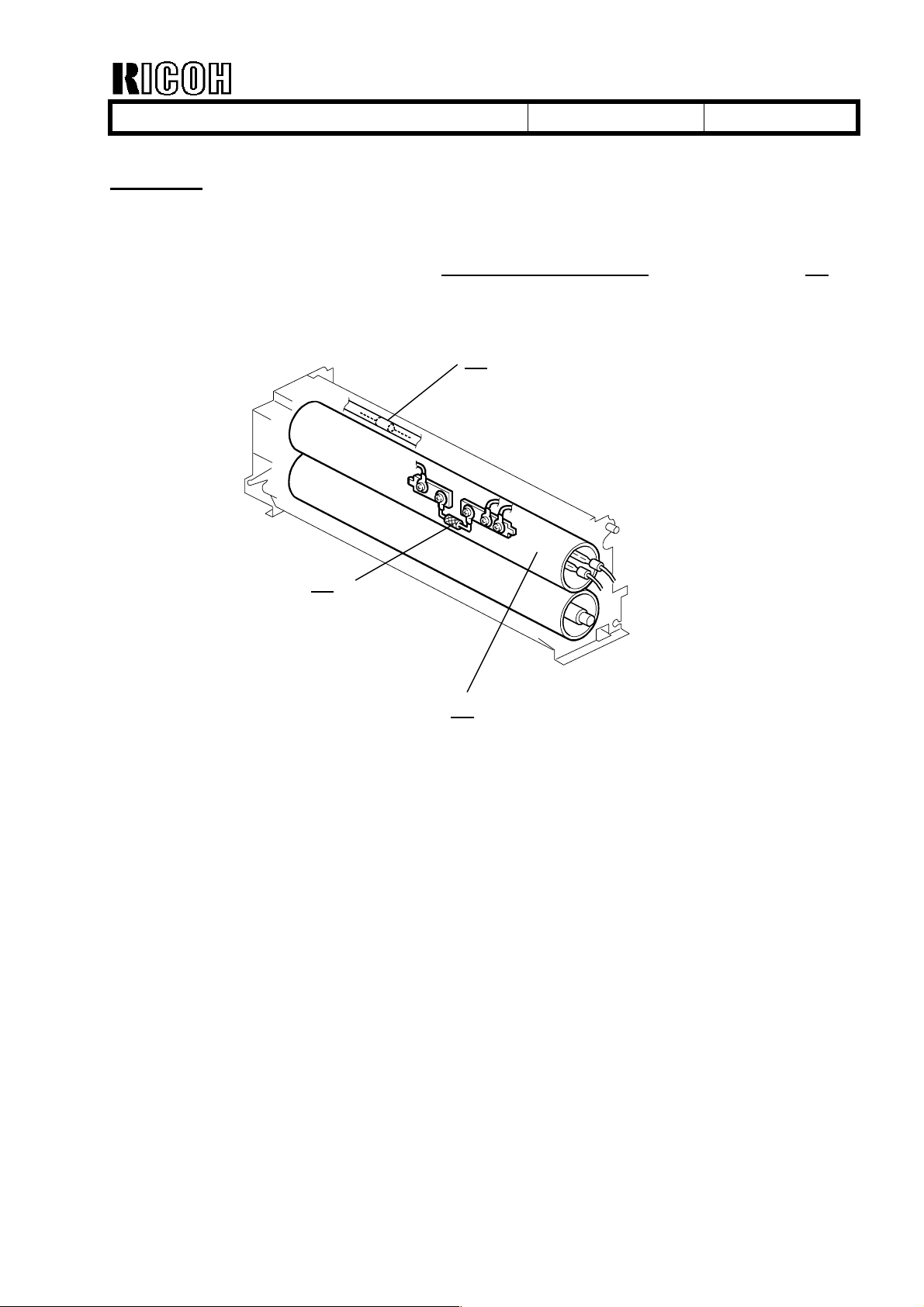
Page 6-53 6.10.6 HOT ROLLER THERMOFUSE
Corrected: Description and illustration.
Dolphin
Non-contact thermofuses (rated for 192°C [A] and 216°C [B]) near the hot roller [C]
prevent accidental overheating which may lead to a fire hazard.
[B]
Date:
23-Aug-01
No.:
RB010001
[A]
[C]
Page 4

echnical Bulletin
T
PAGE: 1/1
Model:
Subject:
From:
Dolphin
HDD Spindle Control Setting (SP4960 005,006)
Technical Services Dept., GTS Division
Classification:
Troubleshooting
Mechanical
Paper path
Other ( )
Part information
Electrical
Transmit/receive
Date:
23-Aug-01
Prepared by:
No.:
RB010002
F. Noguchi
Action required
Service manual revision
Retrofit information
SYMPTOM
When HDD Spindle Control is disabled (default), SC980 may occur just after the machine
recovers from Auto Off / Panel Off.
CAUSE
When the machine is brought out of these modes, it is able to warm up quicker than when
the main power is turned on, and therefore checks the HDD status at an earlier point.
However since the HDD must warm up from a stop, it does not reach the ready speed in
time and a mainframe/HDD communication error occurs.
SOLUTION
The default setting for HDD Spindle Control (SP4960-005, 006) has been changed from
Off ! On, which keeps the HDD rotating constantly.
Cut-in serial numbers:
B010-17: From 1st production
B010-22: From 1st production
B017-27: From J201070001
ACTION IN THE FIELD
When installing the HDD option in the following machines, please change the setting of
SP4960-005 and 006 from Off ! On:
B010-27: J201060001 – J201060040 (40 units)
Page 5
echnical Bulletin
T
PAGE: 1/3
Model:
Subject:
From:
Dolphin
BICU & SCU Firmware Modification History
Technical Services Dept., GTS Division
Classification:
Troubleshooting
Mechanical
Paper path
Other ( )
Part information
Electrical
Transmit/receive
Date:
07-Sep-01
Prepared by:
No.:
RB010003
F. Noguchi
Action required
Service manual revision
Retrofit information
This RTB contains the modification histories for the BICU and SCU firmware.
Note: When installing either the BiCU or SCU firmware in the field, be sure to update both
together.
Part NumberDestination
BICU SCU
USA B0105162 B0105172 B010-17: US English
EU1, Asia B0105163 B0105173 B010-22,-27: English
EU2 B0105180 B0105190 B010-22,-27: French
EU3 B0108182 B0105192 B010-22,-27: German
EU4 B0108184 B0105194 B010-22,-27: Italian
EU5 B0105186 B0105196 B010-22,-27: Spanish
EU6 B0105188 B0105198 B010-22,-27: Dutch
Model Codes/Languages
Destination/
Part Number
Version/
Suffix
USA
B0105162
B0105172
Eu1_Asia
B0105163
b0105173
Eu2
B0105180
B0105190
Eu3
B0105182
B0105192
Eu4
B0105184
B0105194
Eu5
B0105186
B0105196
Eu6
B0105188
B0108198
RTB
issue
date
6.00AAAAAAA ---
6.06 B B B B B B B 07-Sep-01
Page 6

echnical Bulletin
T
PAGE: 2/3
Model:
Dolphin
Date:
07-Sep-01
No.:
RB010003
Version 6.06
1. SP4960 005,006 (HDD Spindle Control) setting changed
Symptom
When HDD Spindle Control is disabled (default), SC980 may occur just after the machine
recovers from Auto Off / Panel Off.
Cause:
When the machine is brought out of these modes, it is able to warm up quicker than when the
main power is turned on, and therefore checks the HDD status at an earlier point. However since
the HDD must warm up from a stop, it does not reach ready speed in time and a
mainframe/HDD communication error occurs.
Solution:
The default setting for HDD Spindle Control (SP4960-005, 006) has been changed from
Off ! On, which keeps the HDD rotating constantly.
Cut-in serial numbers:
B010-17, -22: From 1
B010-27 : From J201070001
Note: When installing the HDD option in the following machines, please change the setting of
SP4960-005 and 006 from Off ! On:
B010-27: J201060001 – J201060040 (40 units).
st
production
2. New UP mode added (Weekly Output Volume)
To prevent toner scattering from the development unit (see the conditions below), the “Weekly
Output Volume” setting has been added to System Setting – General Features.
Symptom
When customers use low duty mode to make high-volume copy jobs (relative to the ACV), the
toner concentration in the development unit increases. This causes the oversupplied toner to
drop onto the copies, especially under low temperature conditions.
Solution
Change the “Weekly Output Volume” according to the customer’s average weekly copy volume
from inside System Setting – General Features:
Less than 750m (2,500 ft): Low duty mode (default).
More than 750m (2,500 ft): High duty mode
Action in the field
Please instruct customers on the following points at machine installation:
1) Method for how to enter UP Mode and change the Weekly Output Volume value.
2) For the first 1-2 months following installation, have the customers keep track of their copy
volumes at weekly intervals. The weekly changes in CV over this time will enable them to
decide which of the two settings is best for them.
Note: For customers installing the Dolphin as a replacement machine, please use the weekly
ACV on the previous machine for reference and set the Weekly Output Volume accordingly
(as a starting point).
3) During these first couple of months, if the average weekly copy volume exceeds 750m (2,500
ft), please have the customer change the setting of the Weekly Output Volume to “More than
750m (2,500 ft)”.
Note: Please also check the total counter value at PM visits, calculate the weekly CV, and if
necessary change the Weekly Output Volume setting.
Page 7

echnical Bulletin
T
PAGE: 3/3
Model:
3. 24-inch originals are recognized as 30-inch originals
When 30-inch paper is selected on the operation panel, 24-inch originals are automatically
detected as 30-inch originals.
4. “NRG A070” added to SP5907 (Plug & Display)
The model name NRG A070 has been added as follows:
Dolphin
1: Ricoh Imagio Wide 7040 (Japan)
2: Ricoh Aficio 470W
3: NRG A070
Date:
07-Sep-01
No.:
RB010003
Page 8

echnical Bulletin
T
PAGE: 1/3
Model:
Subject:
From:
Dolphin
Service Manual
Technical Services Dept., GTS Division
Classification:
Troubleshooting
Mechanical
Paper path
Other ( )
Part information
Electrical
Transmit/receive
Date:
22-Oct-01
Prepared by:
No.:
RB010004
F. Noguchi
Action required
Service manual revision
Retrofit information
Please apply the following corrections and additions to your Service Manual Installation
Procedures. In addition, please see the Note on the last page on how to read the factory
settings data sheet.
1. Corrections: Cushion - Rear Copy Tray Holder (B010-22, -27 only).
The “Cushion - Rear Copy Tray Holder (B010-22, -27 only)” was not packed as an
accessory from 1st production.
1) Pg. 1-4: Accessory Checklist.
Delete the “Cushion - Rear Copy Tray Holder (B010-22, -27 only)”.
2) Pg. 1-8: Installation Procedure and Illustration.
Delete Step 16: “Adhere the cushions [F] to the rear copy tray holders [G].”
Delete the cushion [F] (B010I206.WMF) from the illustration.
Illustration correction:
[H]
[I]
[F]
[G]
[F] [H]
[G]
Page 9

echnical Bulletin
T
PAGE: 2/3
Model:
2. Addition: Key Counter Installation Procedure
1) Remove the right front cover [A]
2) Remove the small cover [B] (1 screw)
3) Install the key counter holder [C] by
4) Reinstall the right rear cover.
5) Instruct the key operator on how to
Dolphin
[B]
(5 screws).
and plate nut (2 screws).
attaching it to the bracket (2 screws,
1 connector [D]).
enable the Key Counter from inside User Tools.
(User Tools → System Settings → Key Operator Tools → Key Counter Access)
Date:
[C]
22-Oct-01
No.:
RB010004
[A]
[D]
Note:
Please be sure to set the Key Operator Access code so that only the authorized key
operator is able to change the system settings.
6) Change the following SP Mode settings:
SP5997: Optional Counter Unit
Select “x 1/10” or “x1” for the Key Counter unit.
The machine counter units are as follows:
-17 version machine: Feet, Yards or Meters (depending on SP5980).
-27 version machine: Meters.
SP5120: Mode Clear Option Counter Removed
This SP determines what happens to the copy job settings (magnification, density,
etc.) when the Key Counter is removed or the paper supply runs out midway through
a job.
0: Yes (default): Job settings and job are cleared
1: Stand-by : Job settings are cleared after the job is completed
2: No : Job settings remain even after job is completed
Page 10

echnical Bulletin
T
PAGE: 3/3
Model:
3. Supplementary information: How to read the factory settings data sheet.
ROM Version: B0105173B B0105163B B0105085B A2325372C
2001/08/07 – 10:39
S/N : J2010800025
Counter : 9999935
Product No. : B0102700025
Dolphin
SCU BICU Operation Panel CSS
Product code
SP 1001-01 Value SP 1926-61 Value SP 7803-01 Value
Date:
22-Oct-01
No.:
RB010004
51010010100 5 05019206100 -12 13078030100 0
51010010200 5 05019206200 -23 15074010100 0
SP 1001-02 Value SP 1920-62 Value SP 7401-01 Value
Note: The following are User Program codes, not SP codes:
05051010300: Panel Off Timer
05051010400: Energy Saver Timer
Page 11

echnical Bulletin
T
PAGE: 1/1
Model:
Subject:
From:
Dolphin
Caution of the toner cartridge installation
Technical Services Dept., GTS Division
Classification:
Troubleshooting
Mechanical
Paper path
Other ( )
Part information
Electrical
Transmit/receive
Date:
06-Nov-01
Prepared by:
No.:
RB010005
F. Noguchi
Action required
Service manual revision
Retrofit information
The four symptoms listed below tend to occur if the toner cartridge is not shaken properly
before it is inserted into the toner hopper. This is because transport and storage conditions
can cause the toner to bunch together, which prevents the toner agitator from rotating
properly.
Please be sure to remind the customer at installation that it is very important to shake the
bottle 5 to 10 times before inserting it into the hopper. This is also mentioned on the decal
on the left side of the machine.
1) The toner supply drive gears (B0103126, AB017539) break.
2) The shaft for these drive gears break.
Note: In this case, it is necessary to replace the development unit.
3) The toner hopper cover opens during copying.
4) Add Toner is displayed again soon after replacing the cartridge.
Page 12

Reissued: 30-Nov-01
echnical Bulletin
T
PAGE: 1/4
Model:
Dolphin
Date:
07-Sep-01
No.:
RB010003a
Version 6.08 has been added.
Subject:
From:
BICU & SCU Firmware Modification History
Technical Services Dept., GTS Division
Classification:
Troubleshooting
Mechanical
Paper path
Other ( )
Part information
Electrical
Transmit/receive
Prepared by:
Action required
Service manual revision
Retrofit information
F. Noguchi
This RTB contains the modification histories for the BICU and SCU firmware.
Note: When installing either the BICU or SCU firmware in the field, be sure to update both
together.
Part NumberDestination
BICU SCU
USA B0105162 B0105172 B010-17: US English
EU1, Asia B0105163 B0105173 B010-22,-27: English
EU2 B0105180 B0105190 B010-22,-27: French
EU3 B0108182 B0105192 B010-22,-27: German
EU4 B0108184 B0105194 B010-22,-27: Italian
EU5 B0105186 B0105196 B010-22,-27: Spanish
EU6 B0105188 B0105198 B010-22,-27: Dutch
Model Codes/Languages
Destination/
Part Number
Version/
Suffix
USA
B0105162
B0105172
Eu1_Asia
B0105163
b0105173
Eu2
B0105180
B0105190
Eu3
B0105182
B0105192
Eu4
B0105184
B0105194
Eu5
B0105186
B0105196
Eu6
B0105188
B0108198
RTB
issue
date
6.00AAAAAAA ---
6.06 B B B B B B B 07-Sep-01
6.08 C C C C C C C 30-Nov-01
Page 13

Reissued: 30-Nov-01
echnical Bulletin
T
PAGE: 2/4
Model:
Dolphin
Date:
07-Sep-01
No.:
RB010003a
Version 6.08
USA EU1 Asia EU2 EU3 EU4 EU5 EU6
BICU B0105162C B0105163C B0105180C B0105182C B0105184C B0105186C B0105188C
SCU B0105172C B0105173C B0105190C B0105192C B0105194C B0105196C B0105198C
Note: Version 6.08 requires the printer/scanner controller.
1. New SP Mode added to enable the Ready Temperature Setting function (SP1917)
This has been added in order to prevent insufficient fusing with translucent paper when making
copies just after the machine is turned on. The settings for this mode are as follows:
1 Mode Number/name Function/ [Setting]
1917 Ready Temp. Setting Select the ready fusing temperature.
[0 ~ 2/ 0 / 1 step]
0: Standard (143ûC)
1: 195°C (
2: 195°C (
2. Default change for Function Reset Timer (System Settings – General Features 2/3)
The default of this mode was changed from "3 seconds" to "instant" for use with the
Printer/Scanner controller.
All paper types/ thickness
)
Translucent thickness 3 & 4
)
3. Design-use SP Modes added
SP5959 and SP5957 have been newly added. However, these are strictly for design use only.
Please do not change the values in the field. The defaults are as follows:
SP5959:OFF
SP5957:Disabled
The following items (4 ~9) have been corrected in this version.
4. SMC printout onto undefined paper sizes
In response to a request from the field, the SMC printouts can now be printed onto any
paper size that can be loaded into the paper trays.
5. Occurrence conditions changed for SC353
SC353 will not be displayed during Toner End.
This was changed because sometimes when copying originals with a very high image area ratio,
SC353 would occur unnecessarily when the ID sensor pattern density dropped and the Near
End condition was detected.
6. Jam Recovery
The machine was sometimes unable to perform successful jam recovery if a jam occurred while
printing out a series of preset jobs.
7. Display error - number of jobs
Even after being cancelled, a preset job is not subtracted from the total job count.
Page 14

Reissued: 30-Nov-01
echnical Bulletin
T
PAGE: 3/4
Model:
8. Part of image missing when printing out "Additional Copies" with electronic sort, mixed
original mode
Following a mixed-original electronic sorting job, the machine is still set to use the paper roll it
did for the last copy.
Therefore when "Additional Copies" are initiated, instead of resetting the paper roll to the initial
one, the machine starts printing out onto the most recently used roll, cutting off some of the
image. The software was corrected so that copies of any additional sets are printed out onto
their correct sizes, i.e. as originally set in the initial job.
9. Unlimited scanning before beginning a copy job
The software was changed so that when the Print Start Trigger is set to "press start key",
originals can be scanned an unlimited number of times before initiating the copy job. Each time a
new scan is initiated, the previous scan data is overwritten.
Dolphin
Date:
07-Sep-01
No.:
RB010003a
Page 15

echnical Bulletin
T
PAGE: 1/1
Model:
Subject:
From:
Dolphin
Serial number sheet for printer/scanner controller
Technical Services Dept., GTS Division
Classification:
Troubleshooting
Mechanical
Paper path
Other ( )
Part information
Electrical
Transmit/receive
Date:
30-Nov-01
Prepared by:
No.:
RB010006
F. Noguchi
Action required
Service manual revision
Retrofit information
With the release of the Printer/Scanner Controller, this RTB has been issued to explain the
serial number sheet and the Controller Board Assembly service part.
1. Serial number sheet for the Printer/Scanner Controller Board
The following serial number sheet is packaged together with the Printer/Scanner
Controller and the Controller Board Assembly service part.
When installing the board, be sure to attach the decal to the outside of the server PC.
Note:
1) The serial number on this sheet is necessary to obtain the RSP files.
2) If the board needs to be replaced again, it will be necessary to replace the serial
number sheet together.
Serial number
P8219105005-C
2. Service parts
The following is the only service part registered for the Printer/Controller Board.
P/N Description Q’ty
G0675900 Controller Board Ass’y 1
Note:
A parts catalog for the Printer/Scanner Controller will not be issued, because the
controller board assembly is the only registered spare part for this item.
Page 16

echnical Bulletin
p
p
T
PAGE: 1/4
Model:
Subject:
From:
Dolphin
MCU breakage
Technical Services Dept., GTS Division
Classification:
Troubleshooting
Mechanical
Paper path
Other ( )
Part information
Electrical
Transmit/receive
Date:
06-Nov-01
Prepared by:
No.:
RB010007
F. Noguchi
Action required
Service manual revision
Retrofit information
SYMPTOM
The machine shuts down after the MCU breaks (only the operation switch LED is lit).
CAUSE
At power off, surge current damages the oscillator circuit IC on the MCU.
SOLUTION
Replace the MCU with the modified one (suffix C) at installation or the next customer visit.
See the attached MCU Replacement Procedure. See page 3 of this RTB.
Added
D105
5VE
C113
20
9
C115
20
VHC04
8
IC131
F
VHC04
11
IC131
R130 10M
F
GND
OSC105
HC-49/U-S:
19.660MHZ
10
GND
Page 17

echnical Bulletin
T
PAGE: 2/4
Model:
Machines for MCU replacement in the field:
B010-17: J2010700056 ~ 80 (25 units)
B010-22: J2010600044, 54, 58, 64, 66, 67, 70 (7 units)
B010-27: J2010600001, 9, 12, 31, 32, 34, 39 (7 units)
Dolphin
J2010800001 ~ 22 (22 units)
J2010900035, 38, 42, 43, 46 ~ 49, 51, 53, 55 ~ 58, 60 (15 units)
J2010700036 ~ 39, 46 ~ 50, 52 ~ 54 (12 units)
J2010800058, 62, 64 (3 units)
J2010900022, 26, 28 (3 units)
J2010700001, 4, 15 ~ 17, 21 ~ 23, 25, 27, 29, 30, 34 (13 units)
J2010800025, 42, 44, 51 (4 unit)
J2010900005 (1 unit)
Date:
06-Nov-01
No.:
RB010007
COUNTERMEASURE
A surge current protection diode has been added to the MCU at the factory from the
following cut-in serial numbers:
B010-17: J2010900032 ~ 34, 36, 37, 39 ~ 41, 44, 45, 50, 52, 54, 59, 61
and from J2011000001
B010-22: J2010600041 ~ 43, 45 ~ 53, 55 ~ 57, 59 ~ 63, 65, 68, 69
J2010700040 ~ 45, 51, 55
J2010800059 ~ 61, 63, 65,
J2010900023 ~ 25, 27 and from J2010900029
B010-27: J2010600002 ~ 8, 10, 11, 13 ~ 30, 33, 35 ~ 38, 40
J2010700002, 3, 5 ~ 14, 18 ~ 20, 24, 26, 28, 31 ~ 33, 35
J2010800023, 24, 26 ~41, 43, 45 ~50, 52 ~57
J2010900001 ~ 8, and from J2010900010
Note: The P/Ns for the MCU have not been changed (NA: B0105071, EU: B0105076).
The suffix has been changed for both from B to C.
Page 18

echnical Bulletin
T
PAGE: 3/4
Model:
Dolphin
Date:
06-Nov-01
No.:
RB010007
ACTION IN THE FIELD
At installation or the next customer visit, please use the following procedure to replace the
MCU with the modified one (suffix C).
After replacing the MCU, please send back the old MCU (suffix A or B) to the location that
sent you the new MCU.
MCU REPLACEMENT PROCEDURE
Caution: Be sure to unplug the power cord before starting the following procedure.
1. Remove the right rear cover [A]
(5 screws).
[A]
[C]
2. Release the lock of CN251 and
CN254, then pull out the flat cables [B]
from the MCU board [C].
3. Remove the MCU board (3 screws).
[D]
4. Remove the following NVRAMs
from the MCU board:
IC101 [D] (RAM - STK15C68 - P45)
IC108 [E] (SRAM - STK15C88 - W45)
IC109 [F] (RAM - STK15C88 - P45)
Note:
1) Before removal and insertion, the engineer should touch a metal portion of the
machine to eliminate the possibility of a static electricity buildup.
2) Do not place the NVRAM on an object made of conductive material. This will cause a
short, resulting in the loss of all the data inside.
[E]
[B]
[F]
Page 19

echnical Bulletin
T
PAGE: 4/4
Model:
3) When removing the NVRAM, inserting a small, flat-head (standard) screwdriver into
4) When inserting the NVRAM, it is important to first make sure that all of the pins on
5. Mount these 3 NVRAMs onto the new MCU board.
6. Install the new MCU board and connect the flat cables.
7. Plug in the power cord and turn on the main power switch.
8. Confirm the machine serial number using SP5811.
9. Make a copy and confirm that the machine functions normally.
10.Turn off the main power switch and unplug the power cord.
11. Reinstall the right rear cover (5 screws).
Dolphin
the space between the NVRAM casing and the RAM socket (at the ends where there
are no pins), lifting the RAM up on both ends with the screwdriver, and finally taking it
out by hand.
both sides have been properly set in their holes, and then to push the pins in all the
way (in this order).
Date:
06-Nov-01
No.:
RB010007
 Loading...