

Page 1

DOLPHIN
(Machine Code: B010)
SERVICE MANUAL
Page 2

!
IMPORTANT SAFETY NOTICES
PREVENTION OF PHYSICAL INJURY
1. Before disassembling or assembling parts of the copier and peripherals,
make sure that the copier power cord is unplugged.
2. The wall outlet should be near the copier and easily accessible.
3. Note that some components of the copier and the paper tray unit are
supplied with electrical voltage even if the main power switch is turned off.
4. If any adjustment or operation check has to be made with exterior covers off
or open while the main switch is turned on, keep hands away from electrified
or mechanically driven components.
5. If the Start key is pressed before the copier completes the warm-up period
(the Start key starts blinking red and green alternatively), keep hands away
from the mechanical and the electrical components as the copier starts
making copies as soon as the warm-up period is completed.
6. The inside and the metal parts of the fusing unit become extremely hot while
the copier is operating. Be careful to avoid touching those components with
your bare hands.
HEALTH SAFETY CONDITIONS
1. Never operate the copier without the ozone filters installed.
2. Always replace the ozone filters with the specified ones at the specified
intervals.
3. Toner and developer are non-toxic, but if you get either of them in your eyes
by accident, it may cause temporary eye discomfort. Try to remove with eye
drops or flush with water as first aid. If unsuccessful, get medical attention.
OBSERVANCE OF ELECTRICAL SAFETY STANDARDS
1. The copier and its peripherals must be installed and maintained by a
customer service representative who has completed the training course on
those models.
1
Page 3

1. SAFETY AND ECOLOGICAL NOTES FOR DISPOSAL
Do not incinerate toner bottles or used toner. Toner dust may ignite
suddenly when exposed to an open flame.
2. Dispose of used toner, developer, and organic photoconductors in
accordance with local regulations. (These are non-toxic supplies.)
3. Dispose of replaced parts in accordance with local regulations.
4. When keeping used lith iu m batteries in order to dispose of them later, do not
put more than 100 batteries per sealed box. Storing larger numbers or not
sealing them apart may lead to chemical reactions and heat build-up.
Lithium Batteries (Memory Back-up)
!
CAUTION
The danger of explosion exists if a battery of this type is incorrectly
replaced.
Replace only with the same or an equivalent type recommended by the
manufacturer. Discard used batteries in accordance with the
manufacturer’s instructions.
Warning concerning copyright
Many documents are copyrighted. Such documents may not be reproduced by
scanning or in any other form without the express permission of the copyright
holder.
2
Page 4

Conventions in this Manual
This manual uses several symbols.
Symbol What it means
☛
!
"
#
$
%
Refer to section number
See Core Tech Manual for
details
Screw
Connector
E-ring
Clip ring
Lengthwise, SEF
(Short Edge Feed)
Sideways, LEF
(Long Edge Feed)
3
Page 5

TABLE OF CONTENTS
1 INSTALLATION PROCEDURE.................................................... 1-1
1.1 PREPARATION.........................................................................................1-1
1.1.1 ENVIRONMENT...............................................................................1-1
1.1.2 MINIMUM SPACE REQUIREMENTS...............................................1-2
1.1.3 MACHINE LEVEL.............................................................................1-2
1.1.4 POWER SOURCE............................................................................1-3
1.2 COPIER INSTALLATION PROCEDURE ..................................................1-4
1.2.1 ACCESSORY CHECK......................................................................1-4
1.2.2 INSTALLATION PROCEDURE........................................................1-5
1.3 ROLL TRAY INSTALLATION PROCEDURE..........................................1-11
1.3.1 ACCESSORY CHECK....................................................................1-11
1.3.2 INSTALLATION PROCEDURE......................................................1-12
1.4 HDD INSTALLATION PROCEDURE ......................................................1-17
1.4.1 ACCESSORY CHECK....................................................................1-17
1.4.2 INSTALLATION PROCEDURE......................................................1-18
1.5 STAMP BOARD INSTALLATION PROCEDURE....................................1-20
1.5.1 ACCESSORY CHECK....................................................................1-20
1.5.2 INSTALLATION PROCEDURE......................................................1-20
1.6 ORIGINAL TRAY INSTALLATION PROCEDURE...................................1-21
1.6.1 ACCESSORY CHECK....................................................................1-21
1.6.2 INSTALLATION PROCEDURE......................................................1-22
1.7 I/F BOARD INSTALLATION PROCEDURE............................................1-24
1.7.1 ACCESSORY CHECK....................................................................1-24
1.7.2 INSTALLATION PROCEDURE......................................................1-25
2 PREVENTIVE MAINTENANCE.................................................... 2-1
2.1 PM TABLE.................................................................................................2-1
2.2 LUBRICATION POINTS............................................................................2-3
2.2.1 FUSING SECTION...........................................................................2-3
2.2.2 DEVELOPMENT SECTION..............................................................2-3
3 REPLACEMENT AND ADJUSTMENT......................................... 3-1
3.1 OPENING AND CLOSING THE MACHINE...............................................3-1
3.2 EXTERNAL COVERS ...............................................................................3-2
3.2.1 FRONT VIEW...................................................................................3-2
3.2.2 REAR VIEW .....................................................................................3-2
3.3 SCANNER.................................................................................................3-3
3.3.1 OPERATION PANEL........................................................................3-3
3.3.2 ORIGINAL SIZE SENSORS, ORIGINAL SET SENSOR,
ORIGINAL REGISTRATION SENSOR ...........................................3-5
3.3.3 WHITE PLATEN ROLLER................................................................3-6
3.3.4 ORIGINAL UPPER TRANSPORT UNIT AND EXIT SENSOR.........3-7
3.3.5 ORIGINAL TRANSPORT ROLLER..................................................3-8
3.3.6 CIS (CONTACT IMAGE SENSOR)..................................................3-8
i
Page 6

3.4 AROUND THE DRUM............................................................................... 3-9
3.4.1 VDB (VIDEO DRIVE BOARD)..........................................................3-9
3.4.2 LPH (LED PRINT HEAD).................................................................. 3-9
3.4.3 CHARGE CORONA WIRE, GRID WIRE, WIRE CLEANER...........3-10
3.4.4. QUENCHING LAMPS.....................................................................3-11
3.5 DRUM AND DEVELOPMENT UNIT........................................................3-11
3.5.1 DEVELOPMENT UNIT...................................................................3-11
3.5.2 DEVELOPER..................................................................................3-12
3.5.3 BY-PASS FEED SENSOR, REGISTRATION SENSOR.................3-13
3.5.4 TONER SUPPLY CLUTCH ............................................................3-14
3.5.5 DRUM DRIVE MOTOR...................................................................3-14
3.5.6 DRUM UNIT, ID SENSOR, AND CLEANING BLADE....................3-15
3.6 PAPER FEED..........................................................................................3-17
3.6.1 CUTTER UNIT................................................................................3-17
3.6.2 CUTTING SENSOR AND FEED EXIT ROLLER............................3-18
3.6.3 ROLL TRAY....................................................................................3-19
3.6.4 PAPER FEED DRIVE MOTOR.......................................................3-21
3.6.5 FIRST FEED ROLLER AND CLUTCH...........................................3-21
3.6.6 SECOND FEED ROLLER AND CLUTCH ......................................3-22
3.6.7 REGISTRATION MOTOR ..............................................................3-22
3.6.8 REGISTRATION CLUTCH.............................................................3-23
3.6.9 REGISTRATION ROLLER .............................................................3-23
3.7 TRANSFER UNIT ....................................................................................3-24
3.7.1 TRANSFER AND SEPARATION CORONA WIRES ......................3-24
3.7.2 TRANSPORT UNIT........................................................................3-25
3.7.3 TRANSPORT BELTS.....................................................................3-26
3.8 FUSING SECTION..................................................................................3-27
3.8.1 FUSING UNIT.................................................................................3-27
3.8.2 PAPER JUNCTION GATE SOLENOID/EXIT SENSOR.................3-29
3.8.3 FPDB (FUSING PRESSURE DRIVE BOARD)...............................3-29
3.8.4 HOT ROLLER STRIPPERS/PRESSURE MOTORS......................3-29
3.8.5 PRESSURE ROLLER THERMISTOR............................................3-30
3.8.6 THERMOFUSE/HOT ROLLER THERMISTOR..............................3-30
3.8.7 FUSING CLEANING ROLLER .......................................................3-30
3.8.8 FUSING LAMPS.............................................................................3-31
3.8.9 HOT ROLLER AND PRESSURE ROLLER....................................3-32
3.8.10 FUSING DRIVE MOTOR..............................................................3-34
3.9 BOARDS.................................................................................................3-35
3.9.1 PSU (POWER SUPPLY UNIT).......................................................3-35
3.9.2 IOB (INPUT OUTPUT BOARD), MCU (MAIN CONTROL UNIT)....3-35
3.9.3 IPU (IMAGE PROCESSING UNIT).................................................3-36
3.9.4 HDD REPLACEMENT....................................................................3-36
3.10 ADJUSTMENTS....................................................................................3-37
3.10.1 CIS AND WHITE PLATEN ROLLER ADJUSTMENT ...................3-37
3.10.2 LPH ADJUSTMENT ........................................................................... 3-38
3.10.3 IMAGE POSITION, MAGNIFICATION, MARGIN ADJUSTMENTS....3-41
ii
Page 7

4 TROUBLESHOOTING ................................................................. 4-1
4.1 SERVICE CALL CONDITIONS.................................................................4-1
4.1.1 SUMMARY.......................................................................................4-1
4.2 SC CODE DESCRIPTIONS......................................................................4-2
4.3 JAM CODE TABLE..................................................................................4-18
4.4 COVER OPEN.........................................................................................4-19
4.5 IMAGE DATA PROCESSING FLOW CHART.........................................4-20
4.5.1 DATA FLOW IN 1-TO-1 COPY MODE...........................................4-20
4.5.2 DATA FLOW IN REPEAT COPY MODE........................................4-20
4.5.3 DATA FLOW IN SCANNING MODE...............................................4-21
4.5.4 DATA FLOW IN PRINTING MODE (A0 OR SMALLER).................4-21
4.5.5 DATA FLOW IN PRINTING MODE (LARGER THAN A0)..............4-22
4.5.6 DATA FLOW IN TEST PATTERN PRINTING................................4-22
4.6 IMAGE PROBLEM TROUBLESHOOTING .............................................4-23
4.6.1 FLOW CHART................................................................................4-23
4.6.2 SCANNING.....................................................................................4-24
4.6.3 PRINTING ......................................................................................4-26
5 SERVICE TABLES....................................................................... 5-1
5.1 SOFTWARE UPGRADING .......................................................................5-1
5.1.1 OVERVIEW......................................................................................5-1
5.1.2 UPGRADING THE SCU FIRMWARE...............................................5-2
5.1.3 UPGRADING THE BICU FIRMWARE..............................................5-4
5.1.4 UPGRADING THE SCU AND BICU TOGETHER............................5-5
5.1.5 UPGRADING THE AMDP FIRMWARE............................................5-6
5.2 UP (USER PROGRAM) MODE.................................................................5-7
5.2.1 INITIAL SYSTEM SETTINGS...........................................................5-7
5.2.2 INITIAL COPIER SETTINGS............................................................5-8
5.3 SERVICE PROGRAM (SP) MODES.......................................................5-10
5.3.1 ENTERING SP MODE....................................................................5-10
5.3.2 HOW TO USE THE SP MODE .......................................................5-12
5.4 TOUCH PANEL CALIBRATION..............................................................5-14
5.5 SOFTWARE RESET...............................................................................5-14
5.6 PRINTING TEST PATTERNS.................................................................5-15
5.6.1 IMAGE PROCESSING TEST PATTERNS.....................................5-15
5.6.2 IMAGE DATA PATH TEST PATTERNS.........................................5-16
5.7 INPUT CHECK........................................................................................5-17
5.8 OUTPUT CHECK....................................................................................5-20
5.9 SP (SERVICE PROGRAM) MODE TABLES...........................................5-21
6 DETAILED DESCRIPTIONS......................................................... 6-1
6.1 OVERVIEW...............................................................................................6-1
6.1.1 MACHINE LAYOUT..........................................................................6-1
6.1.2 MECHANICAL COMPONENT LAYOUT...........................................6-2
6.1.3 DRIVE LAYOUT...............................................................................6-4
6.1.4 ORIGINAL/COPY PAPER PATHS ...................................................6-5
iii
Page 8

6.2 SCANNER.................................................................................................6-6
6.2.1 OVERVIEW......................................................................................6-6
6.2.2 ORIGINAL SIZE DETECTION..........................................................6-7
6.2.3 ORIGINAL FEED MECHANISM.......................................................6-7
6.2.4 ORIGINAL FEED SPEED.................................................................6-7
6.2.5 ORIGINAL TEMPORARY DELAY....................................................6-8
6.2.6 SCANNING MECHANISM................................................................6-8
6.2.7 AUTO IMAGE DENSITY CORRECTION..........................................6-9
6.2.8 ORIGINAL EXIT SWITCHING MECHANISM ...................................6-9
6.3 IMAGE PROCESSING............................................................................6-10
6.3.1 GENERAL IMAGE PROCESSING FLOW CHART ........................6-10
6.3.2 ORIGINAL MODES........................................................................6-11
Overview............................................................................................. 6-11
Text Mode...........................................................................................6-12
Photo Mode ........................................................................................ 6-13
Text/Photo Mode ................................................................................6-14
Pale Mode...........................................................................................6-15
Generation..........................................................................................6-16
Patched Original Mode.......................................................................6-17
Blue Line Mode...................................................................................6-18
Photo (Hard Tone) Mode....................................................................6-19
6.3.3 INDEPENDENT DOT ERASURE...................................................6-20
6.3.4 FOUR-VALUE ERROR DIFFUSION..............................................6-21
6.3.5 MTF SETTINGS.............................................................................6-21
6.4 AROUND THE DRUM.............................................................................6-22
6.4.1 OVERVIEW....................................................................................6-22
6.4.2 DRUM DRIVE.................................................................................6-23
6.4.3 CHARGE CORONA UNIT..............................................................6-23
6.4.4 CORONA WIRE CLEANING..........................................................6-23
6.4.5 CLEANING THE DRUM .................................................................6-24
6.4.6 COLLECTING USED TONER........................................................6-25
6.4.7 QUENCHING..................................................................................6-26
6.4.8 ANTI-CONDENSATION HEATERS................................................6-26
6.5 IMAGE WRITING....................................................................................6-27
6.5.1 LED HEADS...................................................................................6-27
6.6 DEVELOPMENT.....................................................................................6-28
6.6.1 OVERVIEW....................................................................................6-28
6.6.2 DEVELOPER CROSS-MIXING......................................................6-29
6.6.3 DEVELOPMENT BIAS...................................................................6-30
Copying...............................................................................................6-30
Making ID Sensor Patterns.................................................................6-30
6.6.4 DEVELOPMENT DRIVE MECHANISM..........................................6-31
6.6.5 TONER SUPPLY MECHANISM.....................................................6-31
6.6.6 ID SENSOR....................................................................................6-31
6.6.7 TONER END/NEAR-END CONTROL ............................................6-32
6.6.8 TONER END RECOVERY ............................................................. 6-33
6.6.9 TONER DENSITY CONTROL........................................................6-34
6.6.10 DEVELOPMENT TIMING CHART................................................6-35
iv
Page 9

6.7 PAPER FEED AND REGISTRATION .....................................................6-36
6.7.1 OVERVIEW....................................................................................6-36
6.7.2 PAPER HOLDER............................................................................6-37
6.7.3 PAPER WIDTH AND MEDIA TYPE SETTINGS.............................6-38
6.7.4 ROLL TRAY FEED MECHANISM..................................................6-38
6.7.5 BY-PASS FEED MECHANISM....................................................... 6-39
6.7.6 REGISTRATION.............................................................................6-39
6.7.7 CUTTING MECHANISM.................................................................6-40
6.7.8 ROLL END DETECTION................................................................6-41
6.7.9 CONDENSATION PREVENTION...................................................6-41
6.7.10 PAPER FEED TIMING CHART....................................................6-42
6.8 IMAGE TRANSFER AND PAPER SEPARATION...................................6-43
6.8.1 OVERVIEW....................................................................................6-43
6.8.2 TRANSFER AND SEPARATION TIMING CONTROL....................6-43
6.8.3 PICK-OFF PAWL OPERATION......................................................6-44
6.9 PAPER TRANSPORT.............................................................................6-45
6.9.1 OVERVIEW....................................................................................6-45
6.10 FUSING UNIT........................................................................................6-46
6.10.1 OVERVIEW..................................................................................6-46
6.10.2 FUSING PRESSURE CONTROL MECHANISM...........................6-48
6.10.3 TEMPERATURE AND PRESSURE CONTROL...........................6-49
6.10.4 FUSING CONTROL SETTING TABEL.........................................6-52
6.10.5 HOT ROLLER CLEANING ...........................................................6-53
6.10.6 HOT ROLLER THERMOFUSE.....................................................6-53
6.10.7 FUSING UNIT DRIVE MECHANISM............................................6-53
6.10.8 WRINKLE PREVENTION.............................................................6-54
6.11 PAPER EXIT.........................................................................................6-55
6.11.1 OVERVIEW..................................................................................6-55
6.11.2 PAPER EXIT DRIVE.....................................................................6-55
6.11.3 PAPER EXIT ACCESS.................................................................6-55
6.11.4 SWITCHING EXITS......................................................................6-56
6.11.5 EXIT JAM DETECTION................................................................6-56
6.12 ELECTRICAL COMPONENTS..............................................................6-57
6.12.1 MCU .............................................................................................6-57
6.12.2 IPU................................................................................................6-59
6.12.3 IOB ...............................................................................................6-60
6.12.4 VDB..............................................................................................6-60
6.12.5 RFDB............................................................................................6-60
6.12.6 FPDB............................................................................................6-60
6.12.7 PSU..............................................................................................6-61
SPECIFICATIONS
1 COPIER ENGINE.................................................................................SPEC-1
2 2ND ROLL TRAY (OPTION)................................................................SPEC-4
3 MACHINE CONFIGURATION..............................................................SPEC-5
v
Page 10

25 May, 2001 PREPARATION
1. INSTALLATION PROCEDURE
1.1 PREPARATION
1.1.1 ENVIRONMENT
1. Temperature Range:
2. Humidity Range: 15% to 80% RH
3. Ambient Illumination: Less than 1,500 Lux (do not expose to direct
4. Ventilation: Minimum space 20 m3 (approx. 700 cubic ft.)
5. Ambient Dust: Less than 0.075 mg/m
6. If the installation place is air-conditioned or heated, place the machine as
follows:
a) Where it will not be subjected to sudden temperature changes from low to
high, or vice versa.
b) Where it will not be directly exposed to cool air from an air conditioner in
the summer.
c) Where it will not be directly expo s ed to reflected heat from a spa ce heater
in the winter.
7. Avoid placing the machine in an area filled with corrosive gases.
10°C to 32°C (59°F to 86°F)
sunlight).
Room air should turn over at least 3 times per hour.
3
Installation
8. Avoid any area higher than 2,000 m (6,500 ft) above sea level.
9. Place the machine on a strong and level base.
10. Avoid any area where the machine may be subjected to frequent strong
vibration.
1-1
Page 11
PREPARATION 25 May, 2001
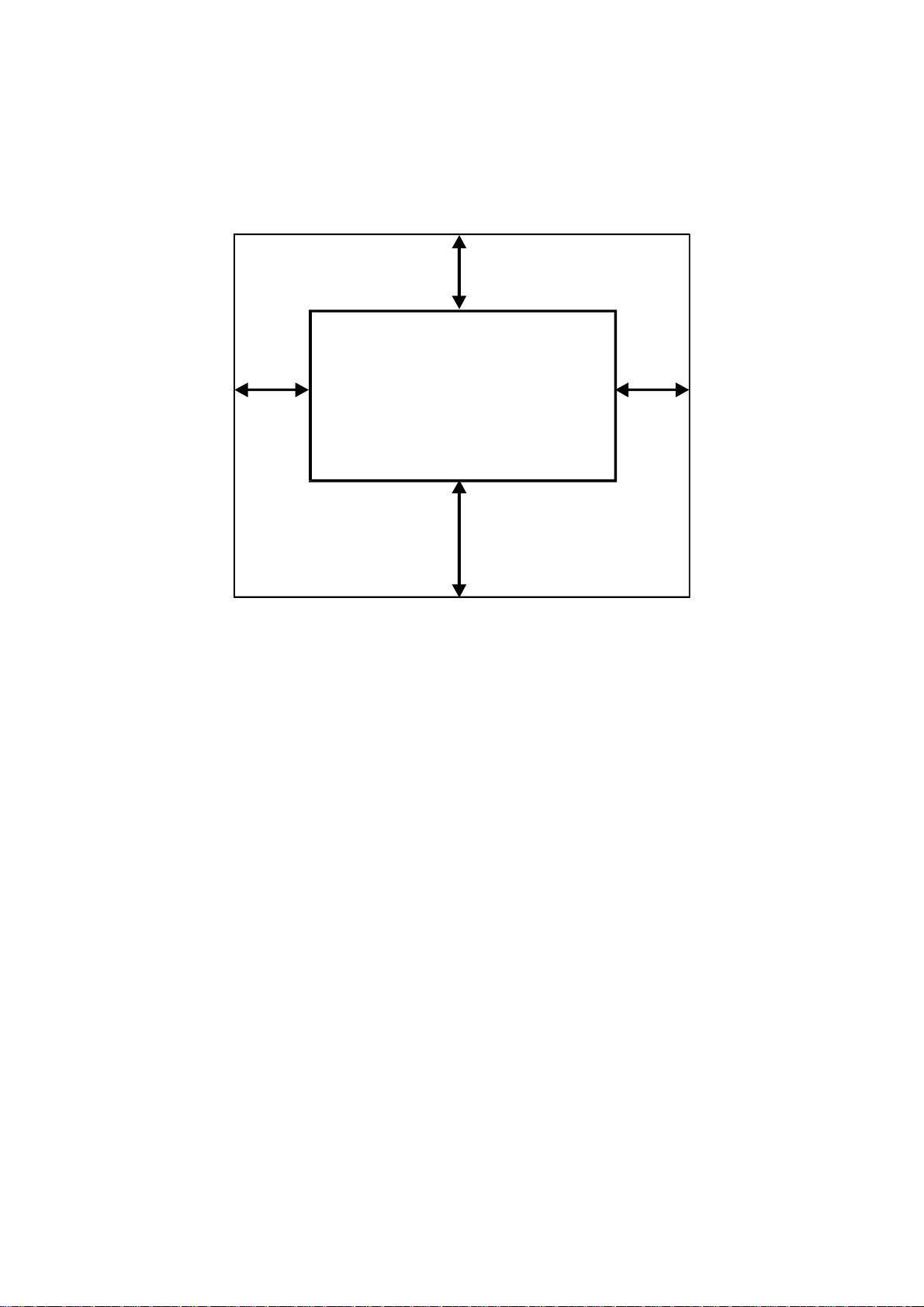
1.1.2 MINIMUM SPACE REQUIREMENTS
Back 450 mm
Left
400 mm
1. Front: 1,000 mm (39")
2. Back: 450 mm (18")
3. Right: 450 mm (18")
4. Left: 400 mm (16")
1.1.3 MACHINE LEVEL
Right
450 mm
Front 1,000 mm
B010I520.WMF
1. Front to back: Within 0.15 mm/1000 mm (0.006”/39.4”) of level
2. Right to left: Within 0.15 mm/1000 mm (0.006”/39.4”) of level
Make sure that the machine is level using a carpente r’s level.
1-2
Page 12

25 May, 2001 PREPARATION
1.1.4 POWER SOURCE
The machine must be installed in a building /facility equipped with a protective
device such as a circuit breaker, as the machine relies on such devices for
protection against over-current and short circuits
1. Input Voltage Level: 120V, 60Hz
More than 20 A (for the U.S.A. version)
220 ~ 240V, 50/60Hz
More than 10 A (for the European version)
Installation
2. Permissible Voltage
± 10%
Fluctuation:
3. Do not set anything on the power cord.
NOTE: 1) Make sure the plug is firmly inserted in the outlet.
2) Avoid multi-wiring.
1-3
Page 13

COPIER INSTALLATION PROCEDURE 25 May, 2001
1.2 COPIER INSTALLATION PROCEDURE
1.2.1 ACCESSORY CHECK
Check the accessories and their quantities against the following list:
Description Q’ty
Paper Holder ........................................................................... 4
Original Guide Tray.................................................................. 1
Original Guide Tray Hinge – Right........................................... 1
Original Guide Tray Hinge – Left............................................. 1
Upper Original Exit Guide........................................................ 3
Upper Original Exit Guide Joint (B010-22, -27 only)................ 2
Rear Original Tray................................................................... 3
Rear Copy Tray Guide - Large ................................................ 1
Rear Copy Tray Guide - Small................................................. 1
Rear Copy Tray....................................................................... 3
Rear Copy Tray Holder............................................................ 3
Cushion - Rear Copy Tray Holder (B010-22, -27 only)............ 3
Guide Mylar - Small................................................................ 3
Guide Mylar - Large................................................................. 1
Front Copy Tray....................................................................... 1
Leveling Shoes........................................................................ 4
Tapping Screw – M4 x 8.......................................................... 6
Screw with Washer – M4 x 10................................................. 2
NECR (B010-17, -27 only).......................................................1
Decal - Operation (B010-22, -27 only).....................................1
Decal - Paper Tray (B010-22, -27 only)...................................1
Decal - Toner Supply (B010-22, -27 only)...............................1
Copy Instructions Guide (B010-17 only)..................................1
System Instructions (B010-17 only).........................................1
1-4
Page 14
25 May, 2001 COPIER INSTALLATION PROCEDURE
1.2.2 INSTALLATION PROCEDURE
NOTE: Since the installation procedure is not packed with the copier as an
accessory, always bring this manual with you.
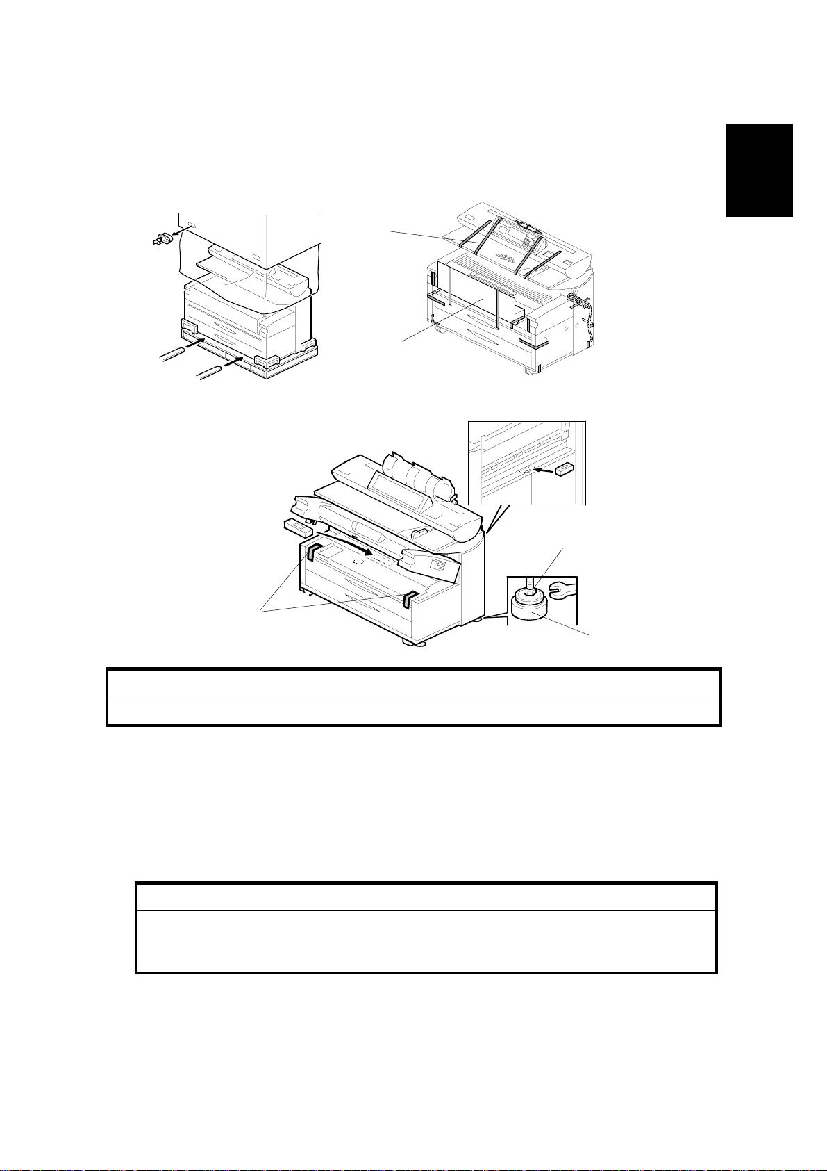
[A]
[B]
Installation
B010I103.WMF
B010I101.WMF
[E]
[C]
[D]
B010I107.WMF
!
CAUTION
Keep the power cord unplugged when starting the following procedure.
NOTE: 1) Keep the shipping retainers after installin g the machine. They will be
reused if the machine is moved to another location in the future.
2) Insert the leveling shoes [D] under the leveling feet [E], and level the
machine before starting the installation.
1. Unpack the machine box and place the copier onto a flat floor using lifting
equipment (a fork lift).
!
CAUTION
The machine weighs approximately 225 kg (496 LB). If a fork lift is not
available, at least 4 people, one on each corner of the machine, are
needed to lift it from the pallet.
2. Remove the upper original tray pack [B] from inside the upper unit.
3. Remove all strips of tape [A], [C] as shown above.
1-5
Page 15
COPIER INSTALLATION PROCEDURE 25 May, 2001
Rear View
[C]
[B]
[H]
[A]
[B]
B010I102.WMF
[G]
[D]
[F]
[C]
[E]
B010I104.WMF
[K]
[L]
[I]
[H]
[M]
B010I212.WMF
[J]
B010I111.WMF
4. Pull out the upper tray [A] and remove strips of tape.
5. Take out the four paper holders [B]. Remove the tapes (x2 each).
6. At the rear, remove two shipping blocks [C] from the original junction gate.
7. Release the lock lever [D]. Open the original feed unit [E] and remove the
cushions and bubble pack [F].
8. At the front, remove the tapes [G], and then from the rear remove the shipping
blocks [H] and tape [I].
9. Open the exit cover [J] and junction gate unit [K], then pull the red ribbon [L] to
remove the protection sheet [M].
1-6
Page 16
25 May, 2001 COPIER INSTALLATION PROCEDURE
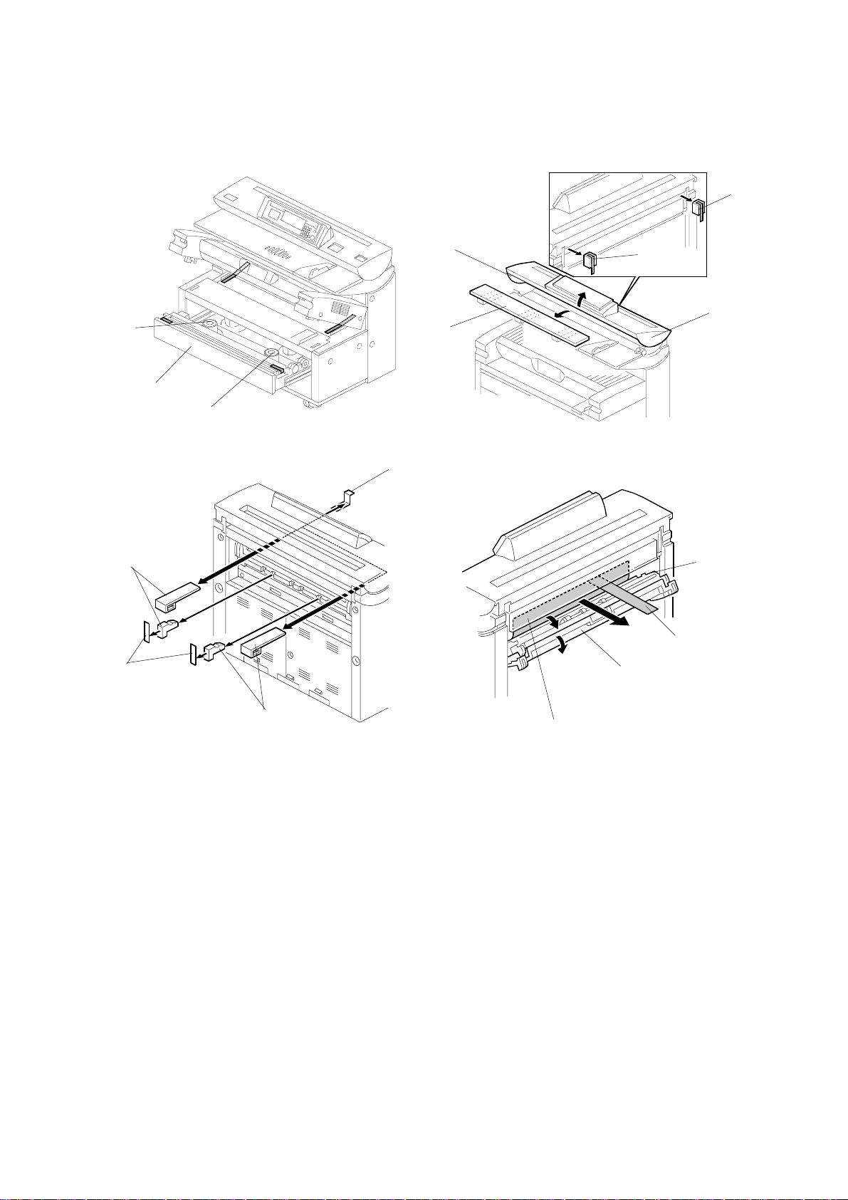
[A]
Installation
[E]
[B]
B010I108.WMF
B010I203.WMF
[F]
[D]
[C]
B010I109.WMF
[F]
[G]
[H]
B010I107.WMF
10. Open the upper unit [A] and remove two strips of tape [B] from the transfer
corona unit.
11. At the front, peel off three strips of tape, and take out the drum protection sheet
[C] by pulling out the red tape.
12. Open the toner hopper cover, remove the left exit tray [D], remove the strip of
tape [E] from the corona wire cleaner, then reinstall the exit tray (! x 2).
!
CAUTION
The tape is looped around the corona wire drive screw. To avoid
damaging the drive screw, gently peel the tape from the mylar or cut it
with scissors.
13. Place a level [F] in the middle of the guide pla te as shown in the illustration.
Make the machine level by turning the bolts [G] on the machine’s four feet.
NOTE: The gap [H] must be less than 2 mm for the bolt to clear the 3rd roll
feeder (option) when the feeder is opened and closed.
1-7
Page 17
COPIER INSTALLATION PROCEDURE 25 May, 2001
[B]
[F]
[G]
[A]
B010I105.WMF
B010I206.WMF
[I]
[B]
[H]
[L]
[D]
[K]
[C]
[E]
B010I106.WMF
[J]
B010I207.WMF
B010I208.WMF
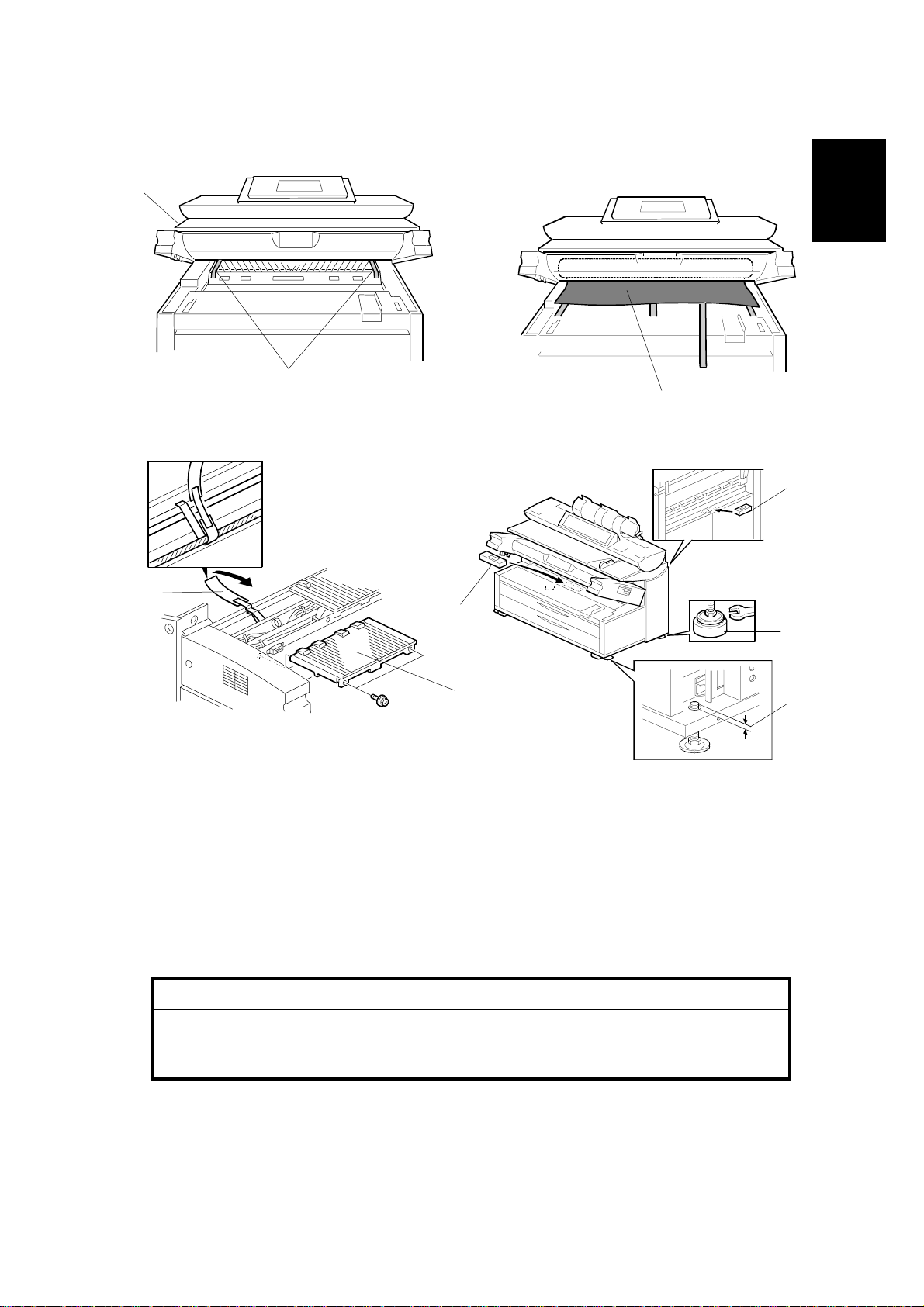
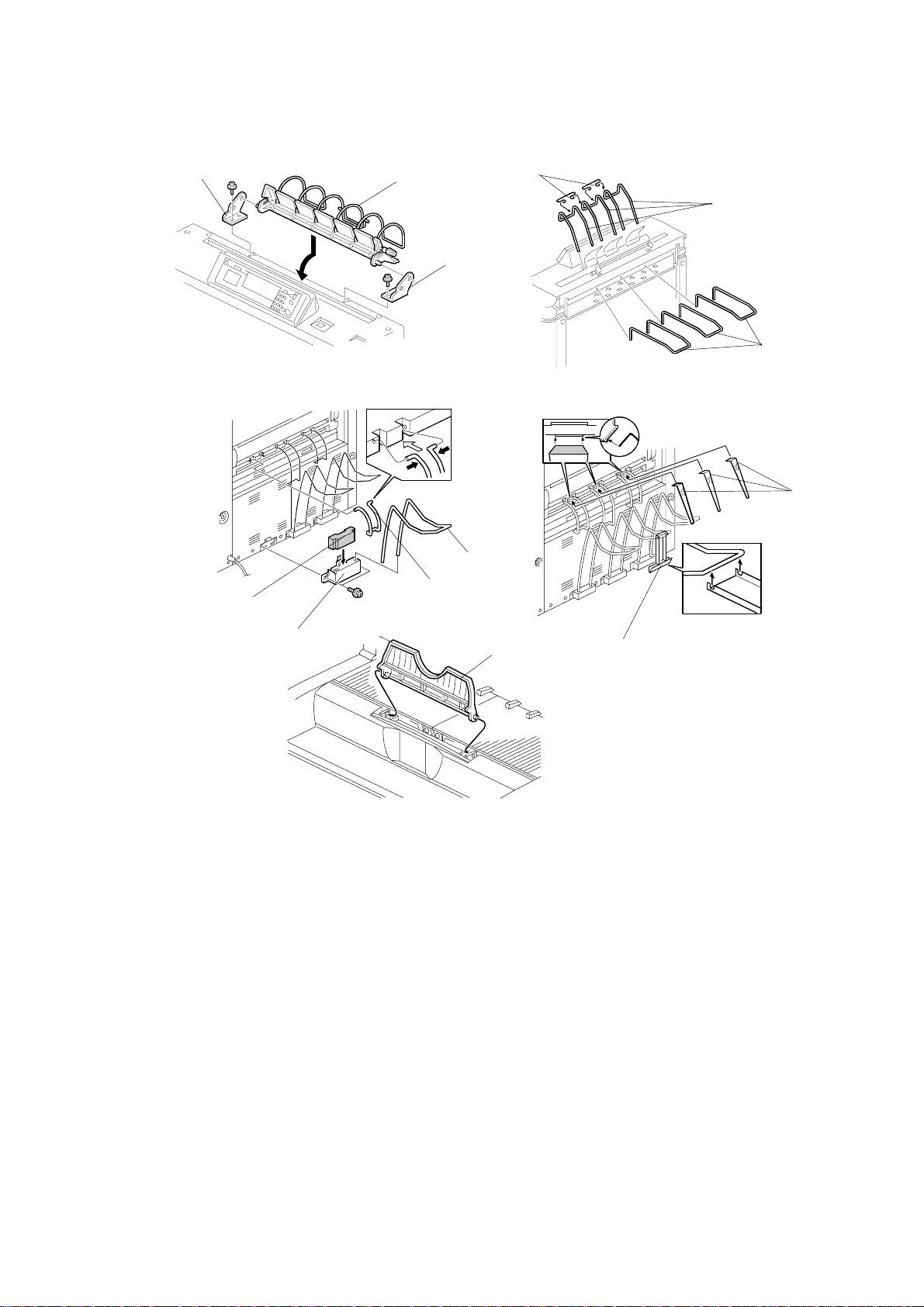
14. Install the upper original tray [A] by using the original guide tray hinges [B] (! x
1 each).
15. Install the upper original exit guides [C], joints [D] and the rear original trays [E].
16. Adhere the cushions [F] to the rear copy tray holders [G].
17. Install the rear copy tray holders (! x 2 each) and insert the rear copy trays [H].
NOTE: The rear copy tray holders must be installed to cover the holes and the
bare section of the frame.
18. Attach the large rear copy tray guide [I] in the center, then attach the two small
rear copy tray guides on either side of the large guide.
19. Attach the small guide mylars [J]. The guide mylars should be on the rear copy
tray guide.
20. Hook the large guide mylar [K] on the rear center copy tray.
21. Attach the front copy tray [L].
1-8
Page 18
25 May, 2001 COPIER INSTALLATION PROCEDURE
[C]
[A]
[D]
[B]
B010I100.WMF
[E]
[F]
Installation
[G]
B010I110.WMF
[H]
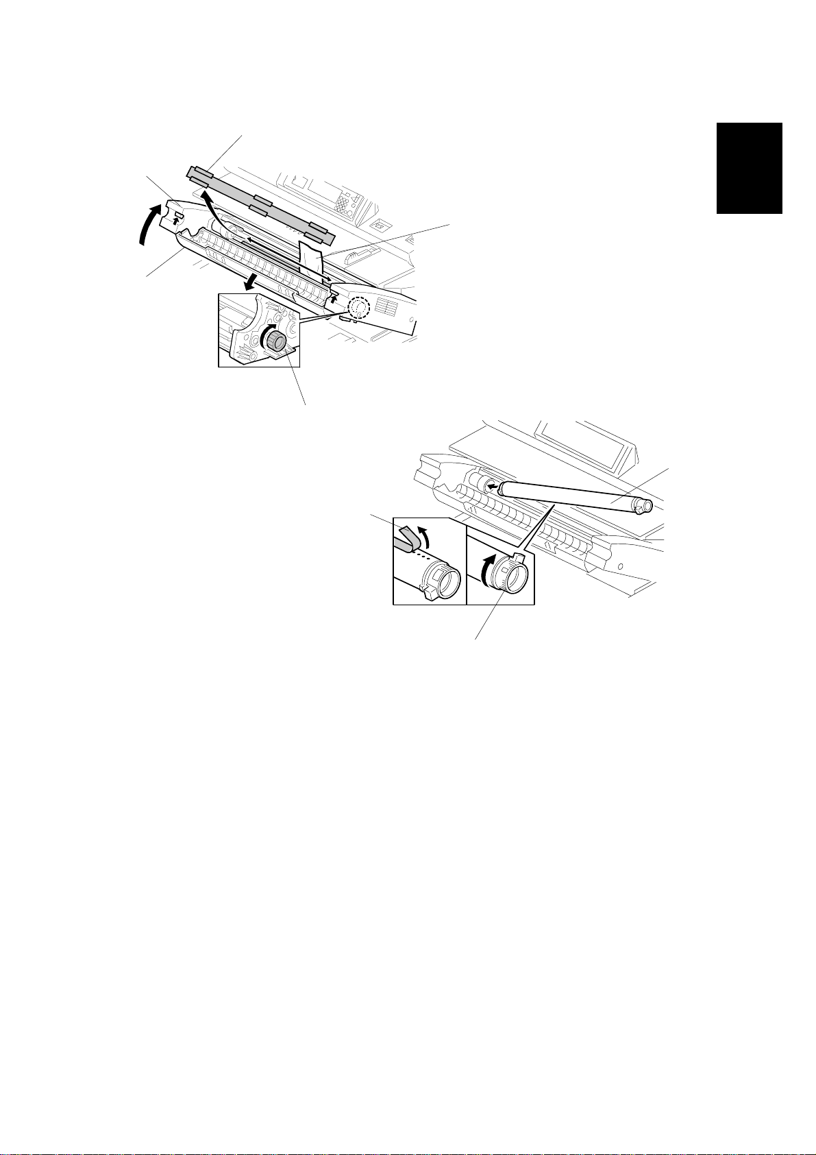
22. Raise the upper unit [A] and open the toner hopper cover [B].
23. Remove the sheet [C] covering the developer entrance.
24. Pour 2.4 kg (1.2 kg x 2) of developer [D] into the development unit evenly
across its width, while rotating the knob [E] clockwise as shown.
25. Install the toner cartridge [F]. Refer to the decal attached on the left side of the
machine.
1) Shake the cartridge 5 to 10 times and insert it into the toner hopper.
2) Peel off the green tape [G] from right to left to expose the clear tape and
toner supply holes.
3) Rotate the knob [H] of the cartridge clockwise until it stops.
26. Close the toner hopper cover and upper unit.
1-9
Page 19
COPIER INSTALLATION PROCEDURE 25 May, 2001
[A]
[B]
B010I521.WMF
27. Plug in the power supply cord and turn on the main switch.
28. Enter SP mode as follows:
1) Press the Clear Modes key
"
.
2) Enter #$%
3) Hold down Clear/Stop & for more than 3 seconds .
4) On the touch panel, press Copy SP.
NOTE: Do not attempt to make copies until after SP3-001-02 has finished in
step 31.
29. To initialize the developer, execute SP2801 (Developer Initial Setting). This
takes two minutes.
30. To initialize the drum, execute SP2923 002 (Drum Set Mode). This takes a few
seconds.
31. Open the upper unit [A], turn the pressure lever [B] to the right to push the
cleaning blade against the drum, then close the upper unit.
32. To initialize the ID sensor, execute SP3001 002. This takes a few seconds.
33. Set SP2924 (Developer Mixing) to “YES”.
34. Exit the SP mode and make copy samples.
1-10
Page 20

25 May, 2001 ROLL TRAY INSTALLATION PROCEDURE
1.3 ROLL TRAY INSTALLATION PROCEDURE
1.3.1 ACCESSORY CHECK
Check the accessories and their quantities against the following list:
Description Q’ty
1. Positioning Pin.....................................................................2
2. Screw – M4x6......................................................................4
3. Flat Harness (taped to right side of machine)......................1
4. Hexagonal Tapping Screw with Flat Washer – M4 x 8 ........4
5. Screw with Spring Washer – M4 x 6....................................1
6. Right Slide Rail....................................................................1
7. Left Slide Rail ......................................................................1
8. Stepped Screw – M4...........................................................4
9. Screw – M4 x 6....................................................................16
10. Positioning Pins – (M4 x 4)................................................2
11. Harness Clamp – FCW52..................................................2
12. Harness Clamp – LWS-0511Z...........................................2
13. Harness Clamp – LWS-2111Z...........................................1
Installation
14. Tapping Bind Screw M3x6................................................. 4
15. Edging ...............................................................................1
16. Screw – M4x6....................................................................6
17. Decal – Tray 3................................................................... 1
18. Paper Holder ....................................................................2
19. Installation Procedure........................................................1
20. Decal – Operation (B340-27 only) ....................................1
21. Decal – Roll Feeder (B340-27 only)...................................1
1-11
Page 21
ROLL TRAY INSTALLATION PROCEDURE 25 May, 2001
1.3.2 INSTALLATION PROCEDURE
[D]
[C]
[G]
[A]
[E]
[J]
[E]
[B]
B010I501.WMF
[F]
B010I502.WMF
[G]
[I]
[H]
!
CAUTION
1. Unplug the main machine power cord before starting the following procedure.
2. Before starting the installation, insert the leveling shoes under the leveling feet, and
level the machine.
3. The machine is very heavy. To avoid serious injury, make sure that you have a
sufficient number of people to assist, and use proper lifting equipment for lifting or
moving.
4. The feed tray is weighs 32 kg (14.5lbs) and requires at least two people to lift and
install.
B010I503.WMF
NOTE: Keep the shipping retainers after installing the machine. They will be
reused if the machine is moved to another location in the future.
1. Turn off the copier main switch.
2. Remove the following covers:
1) Right front [A] and rear [B] covers (4 screws, 6 screws).
2) Left front [C] and rear [D] covers (4 screws, 6 screws).
3) Rear covers [E] (9 screws).
3. Remove the lower cover [F] and two brackets [G] (2 screws each).
4. Remove the power supply unit [H] (4 screws, 16 connectors).
NOTE: Before removing the Line and Neutral bayonet connectors [I] from the
PSU, mark them “L” and “N” to prevent reversing their positions when they are
re-attached. “L” (Line) is on the right, and “N” (Neutral) is on the left.
5. Remove the toner collection bottle [J]
1-12
Page 22
25 May, 2001 ROLL TRAY INSTALLATION PROCEDURE
[C]
B010I505.WMF
[A, B]
B010I504.WMF
Installation
[E]
[D]
B010I506.WMF
B010I507.WMF
6. Install the right and left slide rails [A] ,[B] (2 stepped screws, 5 screws ea.
M4x6).
7. Install the positioning pins [C] in the center hole on each slide rail.
8. Install the positioning pins [D] (2 screws ea. M4x6).
9. Install two harness clamps [E] (2 tapping bind screws ea. M3x6).
1-13
Page 23
ROLL TRAY INSTALLATION PROCEDURE 25 May, 2001
[C]
[A]
[B]
B010I509.WMF
B010I508.WMF
[H]
[F]
[D]
[G]
[I]
B010I510.WMF
B010I511.WMF
[G]
10. Install the harness clamp [A] and edging [B].
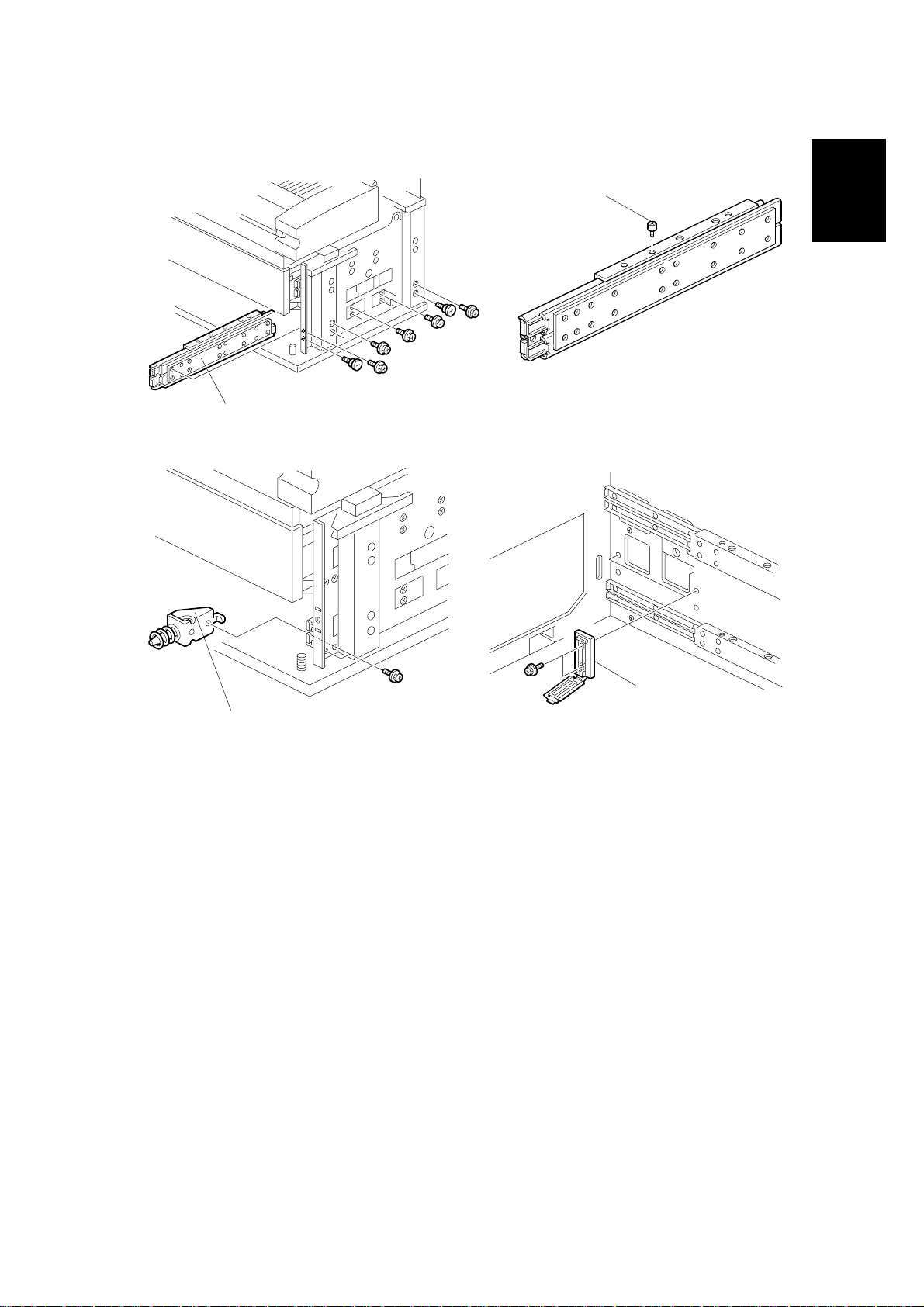
11. Install the connector [C] (4 hex. tapping screws M4 x 8 with flat washers).
12. Loosen the three screws that secure the drawer connector [D].
13. Remove the shipping material from the flat cable [E].
14. Install the 3rd roll feeder [F] on the slide rails, and fit it over the positioning pins
[G].
[E]
15. Use the four screws [H] (2 screws ea. M4 x 6) to attach the tray to the side rails
[I].
1-14
Page 24
25 May, 2001 ROLL TRAY INSTALLATION PROCEDURE
[A]
Installation
B010I513.WMF
Tray 1
[A]
B010I514.WMF
[B]
Tray 2
B010I552.WMF
[B]
[C]
B010I551.WMF
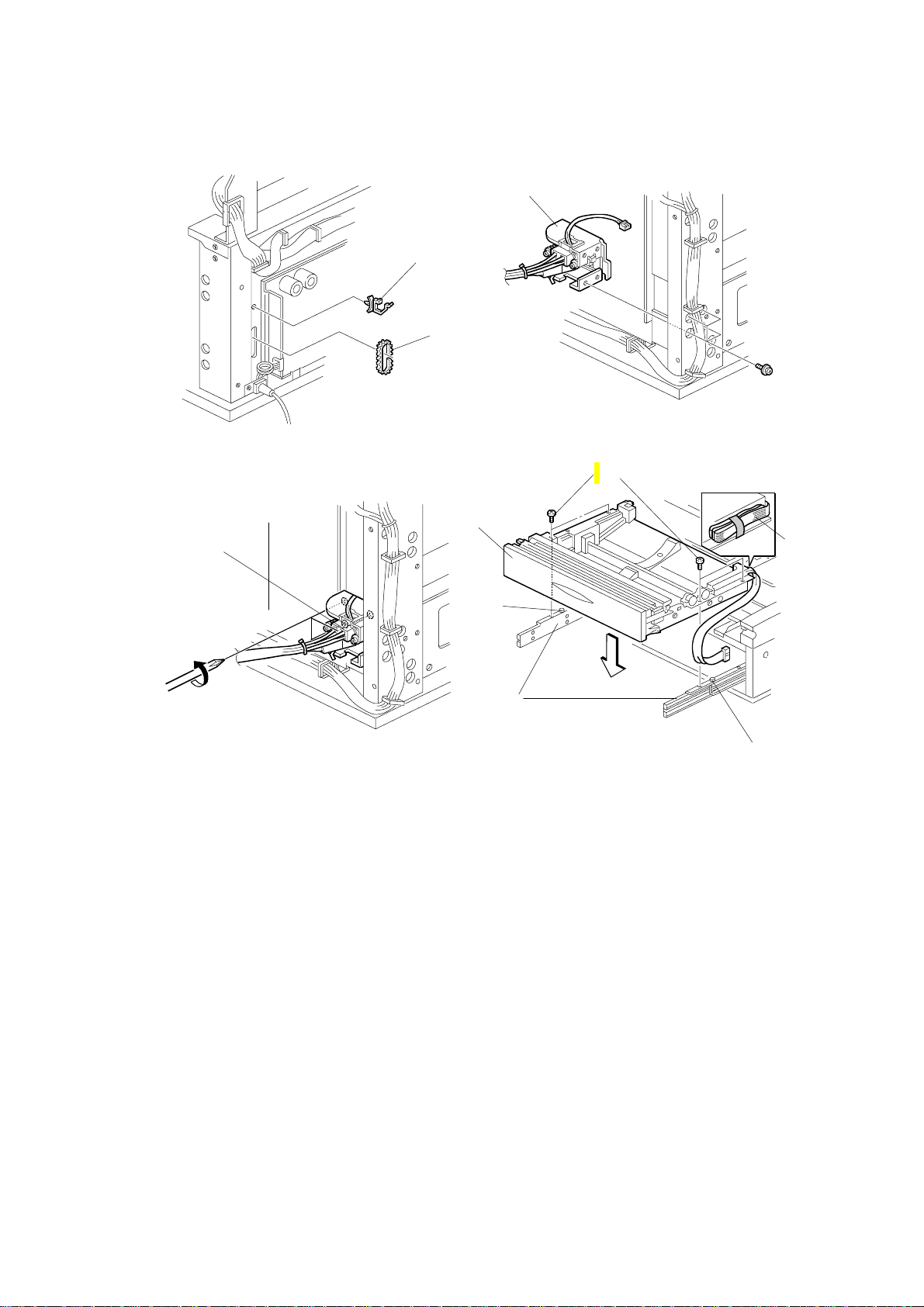
16. Draw out the 3rd roll feeder and route the flat cable [A] as shown.
17. Loosen the positioning brackets [B] of the 3rd roll feeder (2 screws each).
18. Remove the plastic bags from the lock levers and push in the 3rd roll feeder
slowly.
19. Align the positioning bracket and the drawer connector [C] then secure them (2
screws each, 3 screws).
1-15
Page 25
ROLL TRAY INSTALLATION PROCEDURE 25 May, 2001
[B]
[E]
[A]
[G]
[F]
[A]
[D]
[C]
[A]
B010I553.WMF
[I]
[H]
B010I517.WMF
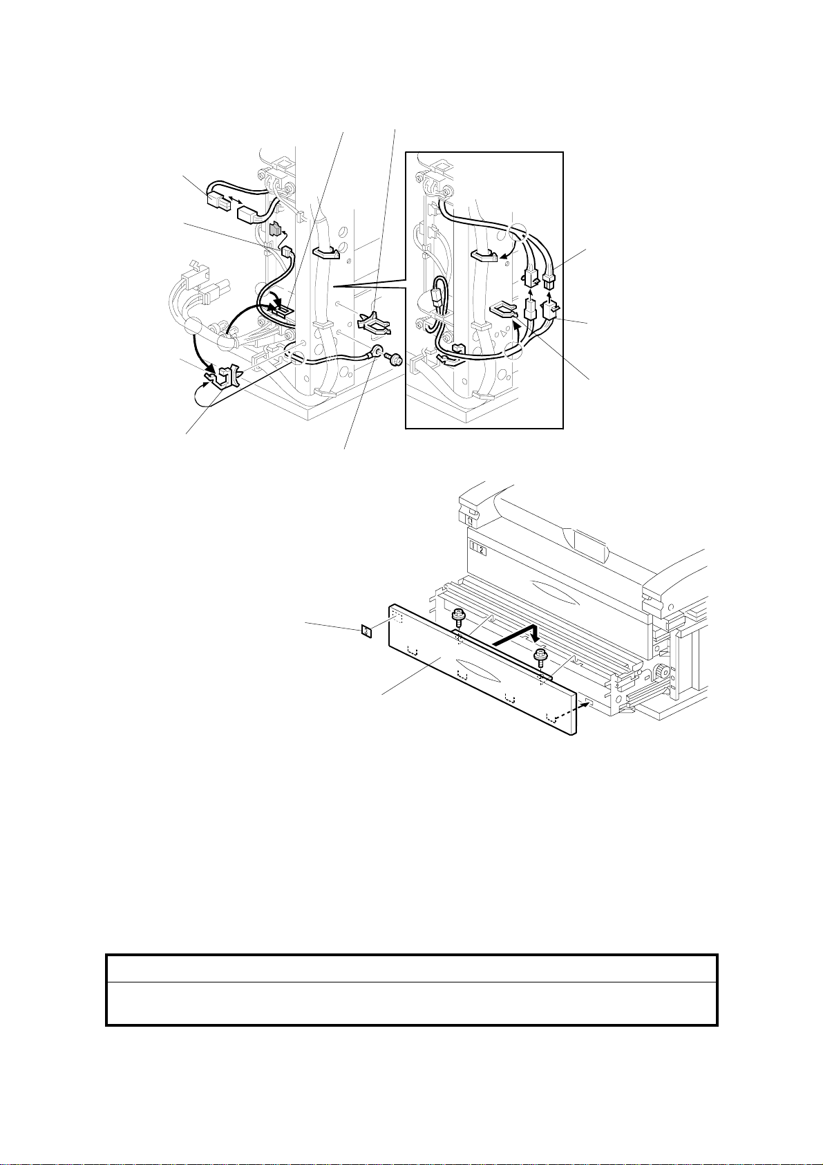
20. Install the two harness clamps [A] and connect the cables [B], [C], [D], and [E].
NOTE: Be sure to clamp cable [C, E] as shown with the pre-installed clamp [F].
21. Secure the ground (earth) wire [G] (1 screw M4x6 with spring washer).
22. Reinstall the lower front cover [H] and attach the decal [I] (2 hex. tapping
screws M4x8 with flat washer).
23. Reinstall the power supply unit, toner collection bottle, and covers.
NOTE: Connect the “N” (Neutral) connector on the left and connect the “L”
(Line) connector on the right.
!
CAUTION
When you position the power supply unit for re-installation, make sure that
the flat ribbon cable is not pinched at the top right.
1-16
Page 26

25 May, 2001 HDD INSTALLATION PROCEDURE
1.4 HDD INSTALLATION PROCEDURE
1.4.1 ACCESSORY CHECK
Check the accessories and their quantities against the following list:
Description Q’ty
1. HDD.....................................................................................1
2. DC Harness – Power Source...............................................1
3. DC Harness.........................................................................2
4. Harness Clamp....................................................................2
5. Philips Tapping Screw – M4 x 8...........................................2
6. Philips Tapping Screw – M3 x 8...........................................2
Installation
1-17
Page 27
HDD INSTALLATION PROCEDURE 25 May, 2001
1.4.2 INSTALLATION PROCEDURE
[A]
B010I521A.WMF
[B]
B010I522.WMF
[C]
[B]
B010I524.WMF
B010I523.WMF
!
CAUTION
Unplug the power cord before starting the following procedure.
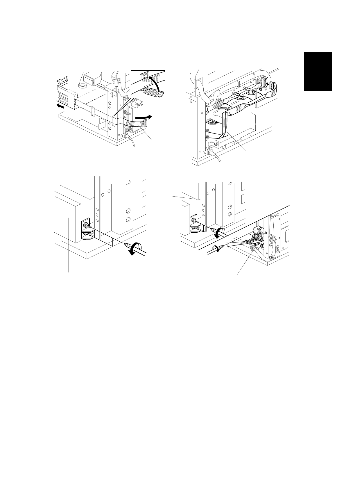
1. Remove the copier right and left rear covers (! x 9).
2. Remove the serial number decal from the HDD unit and attach it on the rear
frame, next to the machine’s serial number decal.
3. Remove 2 cushions from the HDD unit.
4. Install the HDD unit [A] onto the base plate (! x 2).
5. Connect the DC harnesses [B] (! x 1, " x 2 ea.).
6. Connect the power source DC harnesses [C] (" x 3).
1-18
Page 28

25 May, 2001 HDD INSTALLATION PROCEDURE
7. Enter SP mode as follows:
1) Press ".
2) Enter #$%
3) Hold down & for more than 3 seconds.
4) On the touch panel, press Copy SP.
8. Enter 4960 015 (HDD Connection On/Off) and then press On.
9. Turn off the main switch and reassemble the machine.
Installation
1-19
Page 29
STAMP BOARD INSTALLATION PROCEDURE 25 May, 2001
1.5 STAMP BOARD INSTALLATION PROCEDURE
1.5.1 ACCESSORY CHECK
Check the accessories and their quantities against the following list:
Description Q’ty
1. Stamp Board........................................................................1
1.5.2 INSTALLATION PROCEDURE
[B]
[A]
B010I204.WMF
!
CAUTION
Keep the power cord unplugged when doing the following procedure.
1. Remove the copier rear left cover (! x 5).
2. Install the stamp board [A] on the IPU board [B].
3. Plug in the power cord and turn on the main switch.
4. Enter SP mode as follows:
1) Press ".
2) Enter #$%
3) Hold down & for more than 3 seconds.
4) On the touch panel, press Copy SP.
5. Enter 5137 (Stamp Function On/Off), and then press Enabled.
6. Reassemble the machine.
1-20
Page 30

25 May, 2001 ORIGINAL TRAY INSTALLATION PROCEDURE
1.6 ORIGINAL TRAY INST ALLATION PROCEDURE
1.6.1 ACCESSORY CHECK
Check the accessories and their quantities against the following list:
Description Q’ty
1. Base Frame.........................................................................2
2. Base Stay............................................................................2
3. Middle Frame.......................................................................2
4. Original Tray Stay................................................................2
5. Original Tray........................................................................1
6. Size Decal Sheet ................................................................1
7. Original Stopper...................................................................2
8. Original Guide......................................................................2
9. Cap – Base Frame...............................................................2
10. Cap – Original Tray Stay ..................................................2
11. Hexagonal Bolt – M8 x 40..................................................12
12. Washer – 8 mm ................................................................20
Installation
13. Tapping Screw – M4 x 8 ...................................................6
14. Hex Nut – M8 ....................................................................8
15. Caster – φ40......................................................................2
16. Caster – φ40 Stopper.........................................................2
1-21
Page 31

ORIGINAL TRAY INSTALLATION PROCEDURE 25 May, 2001
1.6.2 INSTALLATION PROCEDURE
[E]
[B]
[D]
[E]
[C]
B010I301.WMF
[B]
[A]
[C]
[A]
[H]
[G]
[H]
[F]
B010I302.WMF
1. Snap the casters [A, B] onto the base frames [C].
[A]: Caster – φ40 Stopper
[B]: Caster – φ40
2. Install the base stays [D] on the base frames (4 bolts, 4 washers).
3. Install the caps [E] on the base frame.
4. Install the middle frames [F] (4 bolts, 8 washers, 4 nuts).
5. Install the original tray stays [G] (4 bolts, 8 washers, 4 nuts).
6. Install the caps [H] on the original tray stays.
1-22
Page 32

25 May, 2001 ORIGINAL TRAY INSTALLATION PROCEDURE
A1
A0
[A]
48"
[C]
Installation
34"
36"
44"
B010I305.WMF
[B]
B010I303.WMF
7. Install the original tray [A] on the original tray stays (! x 6).
8. Attach the size decals (A1', A0', 34"', 36"', 44"', 48"').
9. Attach the original stoppers [B] and original guides [C].
B010I304.WMF
1-23
Page 33

I/F BOARD INSTALLATION PROCEDURE 25 May, 2001
1.7 I/F BOARD INSTALLATION PROCEDURE
1.7.1 ACCESSORY CHECK
Check the accessories and their quantities against the following list:
Description Q'ty
I/F Board Kit.............................................................................1
I/F Video Cable........................................................................1
I/F Control Cable .....................................................................1
Tapping screw - M4 x 8...........................................................3
Tapping Screw - M3 x 8...........................................................1
Harness Clamp........................................................................2
Harness Clamp - Small............................................................1
1-24
Page 34

25 May, 2001 I/F BOARD INSTALLATION PROCEDURE
1.7.2 INSTALLATION PROCEDURE
!
CAUTION
Unplug the power cord before starting the following procedure.
1. Remove the following covers.
• Left Rear Cover [A] (6 screws).
• Left Front Cover [B] (4 screws).
• Rear Left Cover [C] (5 screws).
2. Remove the cover bracket [D]
(1 screw).
[C]
[D]
Installation
3. Install the I/F board unit [E] on
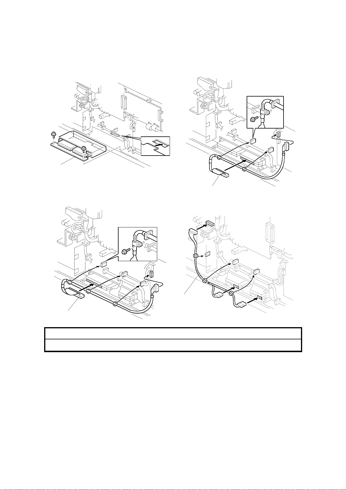
the left frame (3 screws).
4. Connect the I/F Video cable [F] to
the I/F board and IPU board [G]
(1 screw each).
NOTE: Make sure the connector
is inserted completely.
5. Install the wire saddle [H] and
connect the DC harness [I] from
the main frame to the I/F board.
G068I101.WMF
[G]
G068I103.WMF
[B]
[A]
[E]
[H]
[I]
[F]
1-25
Page 35

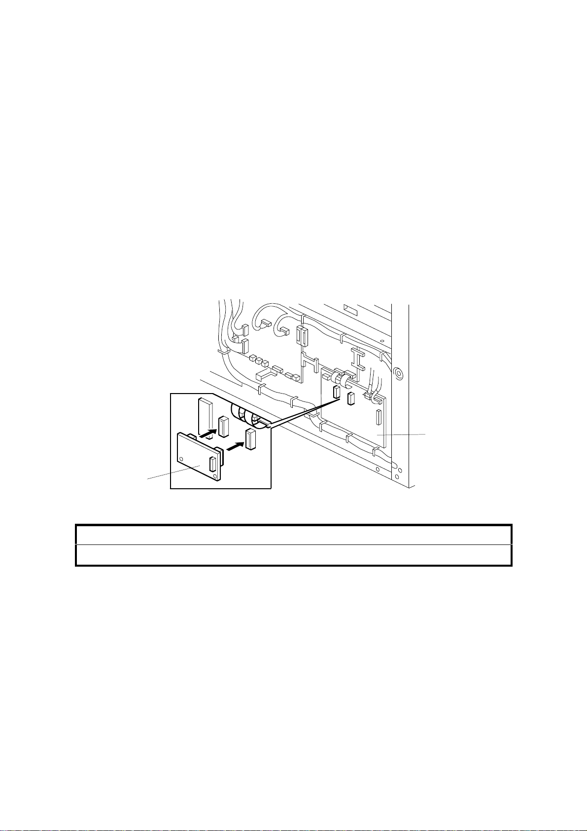
I/F BOARD INSTALLATION PROCEDURE 25 May, 2001
6. Remove the small covers [A, B] from
the left rear and left front covers [C, D]
(2 screws each).
7. Install the following covers.
• Left Front Cover
• Left Rear Cover
• Rear Left Cover
8. Connect the I/F Ctl Cable [E] between I/F board
and printer controller.
[C]
[A]
[D]
G068I102.WMF
[E]
G068I104.WMF
[B]
1-26
Page 36

25 May, 2001 PM TABLE
2. PREVENTIVE MAINTENANCE
2.1 PM TABLE
NOTE: Amounts (K) in the PM Interval column indicate kilometers (1,000 meters).
Symbol key : I: Inspect, R: Replace, C: Clean, L: Lubricate, A: Adjust
Part Number Description Q’ty
Original Feed
Original Feed / Exit Rollers 10K
Original Sensors 60K
Original Table 10K
Optics
White Platen Roller 10K
Exposure Glass 10K
Development
Developer 2 40K
Development Filter 1 20K
Development Roller Gear
Cartridge Holder 10K
Registration Upper Guide Plate 10K
Side Seals 10K
Development Unit Gears
Development Lower Casing 10K
Used Toner Bottle 10K
Cleaning
Cleaning Blade 1 30K
Cleaning Entrance Seal 20K
Side Seals 20K
Pick-off Pawl 20K
Around the Drum
Charge Corona Wire 1 10K
Corona Wire Cleaner Pad 1 10K
Charge Corona Casing 10K
Grid Wire 10K
Transfer Corona Wire 1 10K
Separation Corona Wire 1 10K
T&S Corona Casing / Guide 10K
Quenching Lamp 20K
ID Sensor 20K
LPH (LED Print Heads) 10K
*1
: See 2.2 Lubrication points.
*1
*1
1 200K
PM
Interval
10K
PM Comments
C
Alcohol or water, dr y cloth
C
Blower brush
C
Water, dry cloth
C
Alcohol or water, dr y cloth
C
Water, glass cleaner
R
Replace if necessary.
R
Replace if necessary.
R
Replace if necessary
C
Blower brush, dry cloth.
C
Damp cloth, then dry cloth.
I/C
Dry cloth
L
Silicone Grease G501.
C
Damp cloth, then dry cloth.
I
Empty used toner.
R
Replace if necessary.
C
Dry cloth.
C
Dry cloth.
C
Dry cloth.
C/R
Replace if necessary.
R
Replace.
C
Damp cloth, then dry cloth.
C
Damp cloth, then dry cloth.
C/R Clean with dry cloth. Replace if
necessary.
C/R
Clean with dry cloth. Replace if
necessary.
C
Damp cloth, then dry cloth.
C
Dry cloth
C
Blower brush.
C
Dry cloth. No chemical cleaners.
After wiping, touch to discharge
static.
Preventive
Maintenance
2-1
Page 37

PM TABLE 25 May, 2001
Part Number Description Q’ty
Paper Feed
Cutter Unit 1 10K
Paper Feed / Exit Rollers 10K
Cutting Sensor 20K
Registration Rollers 10K
Registration Sensor 20K
Transport Belt 10K
Timing Belt 10K
Fusing Unit
Hot Roller 1 30K
Fusing Cleaning Roller 1 30K
Bushing – Hot Roller 2 30K
Pressure Roller 1 30K
Hot Roller Stripper 10K
Pressure Roller Stripper 10K
Thermistor 30K
Fusing Exit Guide Plate 10K
Fusing Unit Gears*
Fusing Pressure Screw Shaf t*
2
2
Fusing Drive Gears 10K
Exit Turn Guide 10K
Paper Exit Sensor 10K
Exit Rollers 20K
Others
Ozone Filter 1 10K
*2
: See 2.2 Lubrication points.
PM
Interval
120K
40K
PM Comment
C
Replace if necessary (approx.
service life: 12K cuts)
C
Alcohol, dry cloth
C
Blower brush
C
Alcohol, dry cloth
C
Blower brush
C
Alcohol, dry cloth
I
Adjust tension if necessary.
R
Replace if necessary.
R
Always replace these parts
together.
R
R
Replace if necessary.
C
Dry cloth.
C
Dry cloth.
C
Dry cloth.
C
Alcohol, dry cloth.
L
Barrieta JFE 55/2
L
Barrieta JFE 55/2
L
Silicone Grease G501
C
Damp cloth, then dry cloth.
C
Blower brush
C
Alcohol, dry cloth
R
Replace.
2-2
Page 38

25 May, 2001 LUBRICATION POINTS
2.2 LUBRICATION POINTS
2.2.1 FUSING SECTION
[A]
[C]
B010P506.WMF
[B]
Preventive
Maintenance
[A]: Fusing Gears (Barrieta JFE 55/2)
[B]: Fusing Drive Gears (Silicone Grease G501)
[C]: Fusing Pressure Screw Shaft (Barrieta JFE 55/2)
2.2.2 DEVELOPMENT SECTION
[A, B] Development Unit Gears
(Silicone Grease G501)
NOTE: Development Ro ller Gear [A]
should be checked every 200
km and replaced if necessary.
[A]
[C]
B010P507.WMF
[B]
2-3
B010P303.WMF
Page 39

25 May, 2001 OPENING AND CLOSING THE MACHINE
3. REPLACEMENT AND ADJUSTMENT
!
WARNING
Before you attempt any procedure described in this section, always switch
off the main power switch on the machine and disconnect the machine
from the power source.
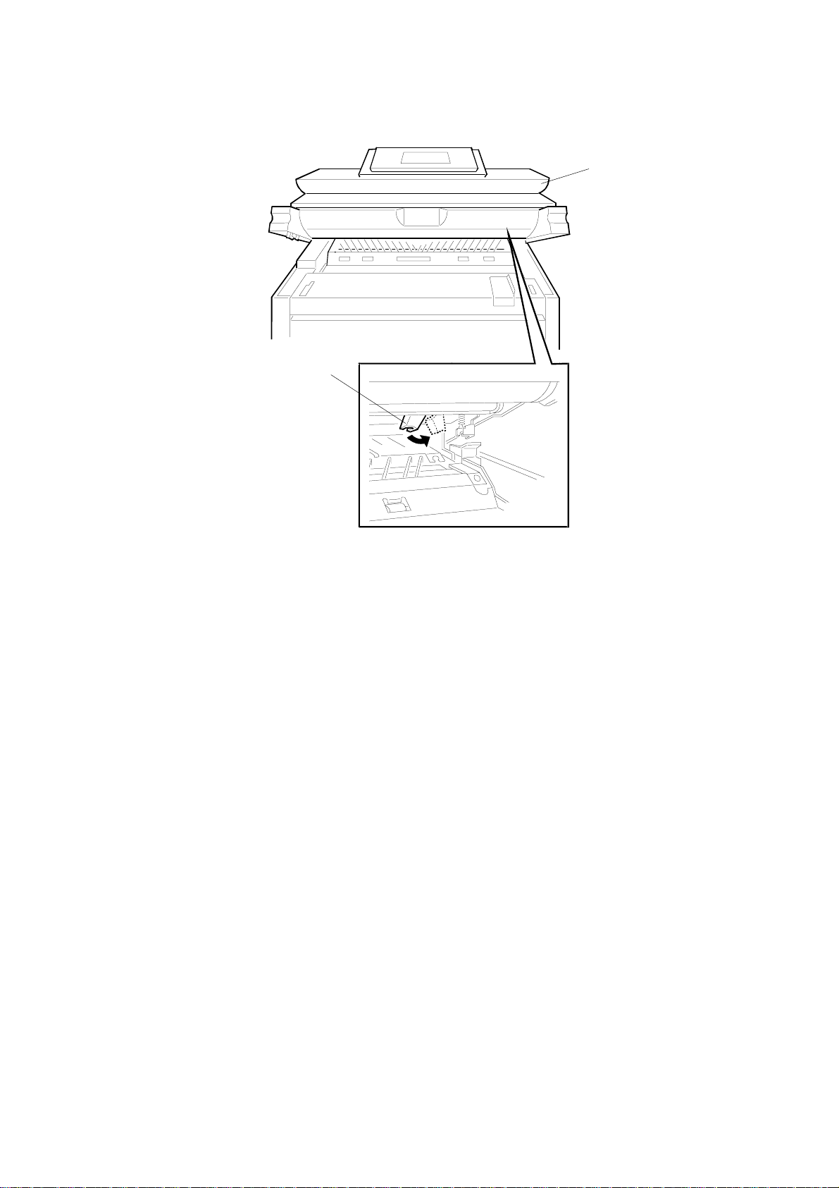
3.1 OPENING AND CLOSING THE MACHINE
[A]
[B]
[F]
Adjustment
Replacement
[C]
[B]
[D]
B010R912.WMF
[A]: Operation panel release
CAUTION: To close the operation panel, always press down evenly on both
sides.
[B]: Upper unit releases
CAUTION: To avoid bending the catch and release mechanisms, always
release and raise the right and left sides together.
[C]: Hopper cover
[D]: Roll tray release
[E]: Paper exit cover
[F]: Paper exit guide plate
[E]
3-1
Page 40

EXTERNAL COVERS 25 May, 2001
3.2 EXTERNAL COVERS
3.2.1 FRONT VIEW
[C]
[H]
[D]
[E]
[G]
[A]: Right rear cover (! x 6)
[B]: Right front cover (! x 4)
[C]: Left rear cover (! x 6)
[D]: Left front cover (! x 4)
[E]: Left inner cover (! x 1)
[I]
[F]
[B]
B010R701.WMF
[F]: Right inner cover (! x 2)
[G]: By-pass feed table (! x 4)
[H]: Left upper unit cover (! x 2)
[I]: Right upper unit cover (! x 2)
[A]
NOTE: Always remove the left and right covers together, the rear cover first and
then the front cover. To avoid scratching the paint on the covers, always
re-attach the front cover first and then the back cover.
3.2.2 REAR VIEW
[A]: Rear right cover (! x 5)
[B]: Rear left cover (! x 5)
[A]
B010R906.WMF
3-2
[B]
Page 41

25 May, 2001 SCANNER
3.3 SCANNER
3.3.1 OPERATION PANEL
[A]: Original roll take-up (! x 2, bracket x
2)
[A]: Left original guide plate (! x 1)
[B]: Right original guide plate (! x 1)
[C]: Operation panel front plate (! x 4)
[A]
[A]
B010R006.WMF
[C]
Adjustment
Replacement
[B]
B010R911.WMF
3-3
Page 42

SCANNER 25 May, 2001
[B]
Open the operation panel unit.
[A]: Lower sensor cover (! x 4)
[B]: Operation panel (! x 4, " x 2)
[C]: Upper scanner cover (! x 6)
[A]
B010R007.WMF
[A]: Scanner stop switch (! x 2, " x 1)
[B]: Operation switch (! x 2, " x 1)
[C]
[B]
[A]
B010R008.WMF
3-4
Page 43

25 May, 2001 SCANNER
3.3.2 ORIGINAL SIZE SENSORS, ORIGINAL SET SENSOR, ORIGINAL REGISTRATION SENSOR
Raise the operation panel unit.
Left, right original guide plates (! x 2) (☛ 3.3.1)
[A]: Operation panel lower cover (! x 4)
[B]: Original path upper bracket (! x 2)
[B]
[A]
B010R001.WMF
➁
[A]: Clamp
➀
Adjustment
Replacement
Original registration sensor
➀
Original set sensor
➁
(A4 Lengthwise)
Original size sensor
➂
(A3 Lengthwise)
Original size sensor
➃
(A2 Lengthwise)
Original size sensor
➄
(A1 Lengthwise)
Original size sensor
➅
(A0 Lengthwise)
*1
US paper sizes.
A*
B
C
D
E
1
➂
➃
➄
➅
B010R002.WMF
[A]
3-5
Page 44

SCANNER 25 May, 2001
3.3.3 WHITE PLATEN ROLLER
[A]: Raise the operation panel unit
[B]: Left operation panel unit cover (! x 2)
[C]: Right operation panel unit cover (! x
2)
[D]: Original table (! x 4)
[A]: Door switch bracket (! x 1)
[B]: Original transport guide (! x 4)
[A]
[B]
[D]
B010R003.WMF
[C]
[A]
[A]: Remove.
[B]: Loosen but do not remove.
[C]: White platen roller.
• Press the white platen roller out to
the left to remove it.
• Lift straight out to prevent the
stopper or gear from dropping off
either end.
• Before re-inst allation, make sure
the stopper on the left end of the
white platen roller is snug, inside
the roller.
SP Adjustment Required After Replacement
SP4428 002
Scanner Adjustment (see
section 3.10.1)
[B]
B010R004.WMF
[A]
[B]
[C]
B010R005.WMF
NOTE: When re-installing, set the right end of the white platen roller first.
3-6
Page 45

25 May, 2001 SCANNER
3.3.4 ORIGINAL UPPER TRANSPORT UNIT AND EXIT SENSOR
Original roll take-up, operation panel,
upper scanner cover, lower sensor cover
(see section 3.3.1)
Lower the operation panel frame.
[A]: Upper original transport unit (! x 2,
" x 1)
[B]: CIS cover (! x 7)
[A]: Original exit unit cover (! x 2)
[B]: Original exit sensor (! x 1)
[B]
[B]
[A]
B010R009.WMF
[A]
Adjustment
Replacement
NOTE: When you re-install the upp er
original transport unit, make sure
that the paper turn guide is below
the pin of the unit below [A].
B010R010.WMF
[A]
B010R567.WMF
3-7
Page 46

SCANNER 25 May, 2001
3.3.5 ORIGINAL TRANSPORT ROLLER
Upper original transport unit (☛ 3.3.4)
[A]: Original transport roller (# x 4)
3.3.6 CIS (CONTACT IMAGE SENSOR)
Upper original transport unit (☛ 3.3.4)
CIS cover (! x 2)
[A]
B010R011.WMF
[A]
[A]: CIS unit (! x 2, " x 3)
SP Adjustment Required After Replacement
SP4428 002
Scanner Adjustment (see
section 3.10.1)
B010R012.WMF
3-8
Page 47

25 May, 2001 AROUND THE DRUM
3.4 AROUND THE DRUM
3.4.1 VDB (VIDEO DRIVE BOARD)
Open the upper unit, and remove the exit tray if
it is attached.
[A]: Left copy tray (! x 2)
[B]: Right copy tray (! x 2)
CAUTION: To avoid damaging the pawls on
the bottom of the covers, hold the cover level
as you pull it straight out.
[C]: VDB (! x 7, " x 7)
3.4.2 LPH (LED PRINT HEAD)
Remove the exit tray if it is attached.
Open the upper unit.
Remove the left and right copy trays
(☛.3.4.1)
Remove the left and right upper unit covers.
( ☛ 3.2)
[A]: LPH connectors on VDB (" x 4)
[B]: Grounding wire (! x1)
[C]: Grounding wire (loosen ! x1)
[D]: LPH
[E]: Three ROMs.
[A]
[E]
[C]
((((
))))
[A]
[B]
****
B010R101.WMF
[B]
B010R555.WMF
++++
[D]
Adjustment
Replacement
• If you intend to replace the LPH, you
must replace the ROMS on the VDB with
the three ROMs provided with the new
LPH kit.
• Reading top to bottom on the board, the
[C]
ROMs are marked LPH-L (left), LPH-C
(center), and LPH-R (right).
• To confirm that each new ROM is
installed in the correct position, match
the numbers of the new ROMs with the
numbers printed on the labels of the LPH
unit.
• Perform an IPU Test Pattern print to
confirm that the joints of the LPH are
aligned correctly and then adjust if necessary. (☛ 3.10.2)
3-9
B010R102.WMF
Page 48

AROUND THE DRUM 25 May, 2001
3.4.3 CHARGE CORONA WIRE, GRID WIRE, WIRE CLE ANER
LPH (☛ 3.4.2)
[A]: Wire cleaner drive motor
bracket (! x 2)
[B]: Remove the white plastic
coupling from the drive screw.
CAUTION: To avoid losing this
coupling, always remove it before
removing the charge corona unit.
[C]: Left, right grounding plate
springs (! x 2)
[D]: Charge corona unit
SP Adjustment Required After
Replacement
SP2803
Charge Corona Wire Cleaning
[B]
➁
[D]
[A]
[C]
➀
B010R550.WMF
NOTE: 1) When removing this unit, shift the unit to the right and lift the left part of
the unit up.
2) Confirm that the grounding plate edge is securely set in the holes.
[D]
[A]: Grid wire
[B]: Right cover
[C]
[B]
[C]: Left cover
[D]: Charge corona wire
[E]: Shock absorbers
[A]: Charge corona wire cleaner
SP Adjustment Required After Replacement
SP2803
Charge Corona Wire Cleaning
[E]
B010R104.WMF
[A]
When replacing wires:
• Make sure the grid wires are correctly
positioned in the correct slots and not
crossed.
• If replacing wires, hold them by the
ends. Oil from hands could cause
B010R105.WMF
uneven charge on the drum.
• Handle wires carefully. Never bend or stretch them.
[A]
3-10
Page 49

25 May, 2001 DRUM AND DEVELOPMENT UNIT
3.4.4 QUENCHING LAMPS
Charge corona unit (☛ 3.4.3)
[A]
[A]: Lamp bracket, left (! x 2, " x 1)
[B]: Lamp bracket, right (! x 2, " x 1)
[C]: Quenching lamp arrays x 2
[C]
3.5 DRUM AND DEVELOPMENT UNIT
3.5.1 DEVELOPMENT UNIT
[A]: Left upper unit cover (! x 2)
[B]: Right upper unit cover (! x 2)
[C]: Right inner cover (! x 2)
[D]: Lower toner cartridge cover.
(Slides out, no screws need to
be removed.)
[A]
[B]
B010R106.WMF
Replacement
[B]
Adjustment
CAUTION: The development unit weighs
10.4 kg (22.9 lb.) with the toner cartridge
installed, or 8 kg (17.6 lb.) without the
toner cartridge.
Raise the upper unit.
[A]: Development bias connector (" x 1)
Make sure the upper unit is open. Do not
attempt to remove the development unit
with the unit closed.
[B]: Development unit (! x 6, " x 1)
CAUTION: To avoid damaging the fragile
wings on either end of the development
unit, never attempt to remove or install the
development unit in the machine with the
upper unit closed.
[D]
[B]
[C]
B010R301X.WMF
[A]
B010R302.WMF
3-11
Page 50

DRUM AND DEVELOPMENT UNIT 25 May, 2001
3.5.2 DEVELOPER
Remove the toner cartridge (follow the
instructions on the decal on the front left
side of the machine.
NOTE: To avoid damaging the bias terminal on
the left end of the development unit,
handle it carefully.
[A]: Toner supply casing (! x 2)
[B]: Development filter and bracket.
NOTE: Make sure that the filter is re-installed
with the holes facing down.
[B]
[A]
[A]: Raise the clutch-end up about 45o to
remove the developer, and then lay to
flat.
[A]: Rotate the unit to remove more developer.
[B]: Rotate the knob to remove the remaining
developer.
[A]
[A]
B010R918.WMF
B010R919.WMF
SP Adjustment Required After Replacement
SP2801 Developer Initial Setting
SP3001 002 ID Sensor Initial Setting
[B]
B010R920.WMF
3-12
Page 51

25 May, 2001 DRUM AND DEVELOPMENT UNIT
3.5.3 BY-PASS FEED SENSOR, REGISTRATION SENSOR
[A]: Development unit (☛ 3.5.1)
[B]: Registration bracket (! x 2)
[C]: Registration guide (! x 2)
[D]: By-pass feed sensor
[E]: Registration sensor
[D]
[A]
[C]
[E]
B010R304.WMF
[B]
Adjustment
Replacement
3-13
Page 52

DRUM AND DEVELOPMENT UNIT 25 May, 2001
3.5.4 TONER SUPPLY CLUTCH
[C]
[A]: Development unit (☛ 3.5.1)
[B]: Toner supply clutch (! x 1, # x 1,
bushing x1, bracket x 1)
[C]: Impeller
NOTE: After re-installing the ton er supply
clutch, make sure that the clutch pin is
inserted correctly in the slot [D] of the
hopper. If not inserted correctly, the
rotating clutch could damage the clutch
cable.
[B]
[D]
[A]
B010R305.WMF
3.5.5 DRUM DRIVE MOTOR
Left covers. (☛ 3.2.1)
[A]: Drum drive motor (! x 4, " x 1)
[A]
B010R303.WMF
3-14
Page 53

25 May, 2001 DRUM AND DEVELOPMENT UNIT
3.5.6 DRUM UNIT, ID SENSOR, AND CLEANING BLADE
Development unit (☛ 3.5.1)
To the right of the drum drive gear, loosen
the screw to relieve the tension on the
drive belt.
[A]: Drum drive gear and belt (! x1, use
a hex wrench)
[B]: ID sensor connector (" x 1)
[C]: Left drum bracket (! x 2)
[D]: Right drum bracket (! x 2)
[E]: OPC drum assembly
NOTE: Cover the OPC with a sheet
of paper to protect it from
light.
[A]: Drum unit left side (! x 1, spring x 1,
bushing x 1)
[B]: Drum unit right side (! x 1, spring x
1, bushing x 1)
[C]: OPC drum
[D]: Rubber plates
When installing a new drum, remove
both rubber plates inside the old
drum and install them in the new
drum. (These plates reduce the
noise caused by inertia when the
drum starts and stops.)
[E]: ID Sensor (! x 1, " x 1)
[F]: Pick-off pawl solenoid (! x 1, " x 1)
[B]
[A]
B010R202.WMF
[A]
[E]
[C]
[E]
[C]
[D]
[B]
B010R201.WMF
[D]
[F]
Adjustment
Replacement
SP Adjustment Required After Drum Replacement
SP2923
SP3001 002
Drum Set Mode (see the next
page)
ID Sensor Setting – Initial
Setting
3-15
Page 54

DRUM AND DEVELOPMENT UNIT 25 May, 2001
[A]: Cleaning blade (! x 2)
SP Adjustment Required After Cleaning Blade
Replacement
SP2923 002 Drum Set Mode – Execute
Drum Set Mode
Make sure that the drum protection sheet
is removed.
1. Set the pressure lever [A] to the left.
[A]
B010R203.WMF
2. Plug in the power cable and switch the
main power switch on.
3. Press ".
[A]
4. Enter #$%
5. Hold down & for more than 3
seconds.
6. On the touch panel, press Copy SP.
7. Enter 2923, press ' , then press Start
to execute Drum Set Mode.
B010R570.WMF
8. After it has finished, set the pressure lever [A] to the right.
9. If you have replaced the OPC drum, enter 3001 002, press ', then press Start
to initialize the ID sensor.
3-16
Page 55

25 May, 2001 PAPER FEED
3.6 PAPER FEED
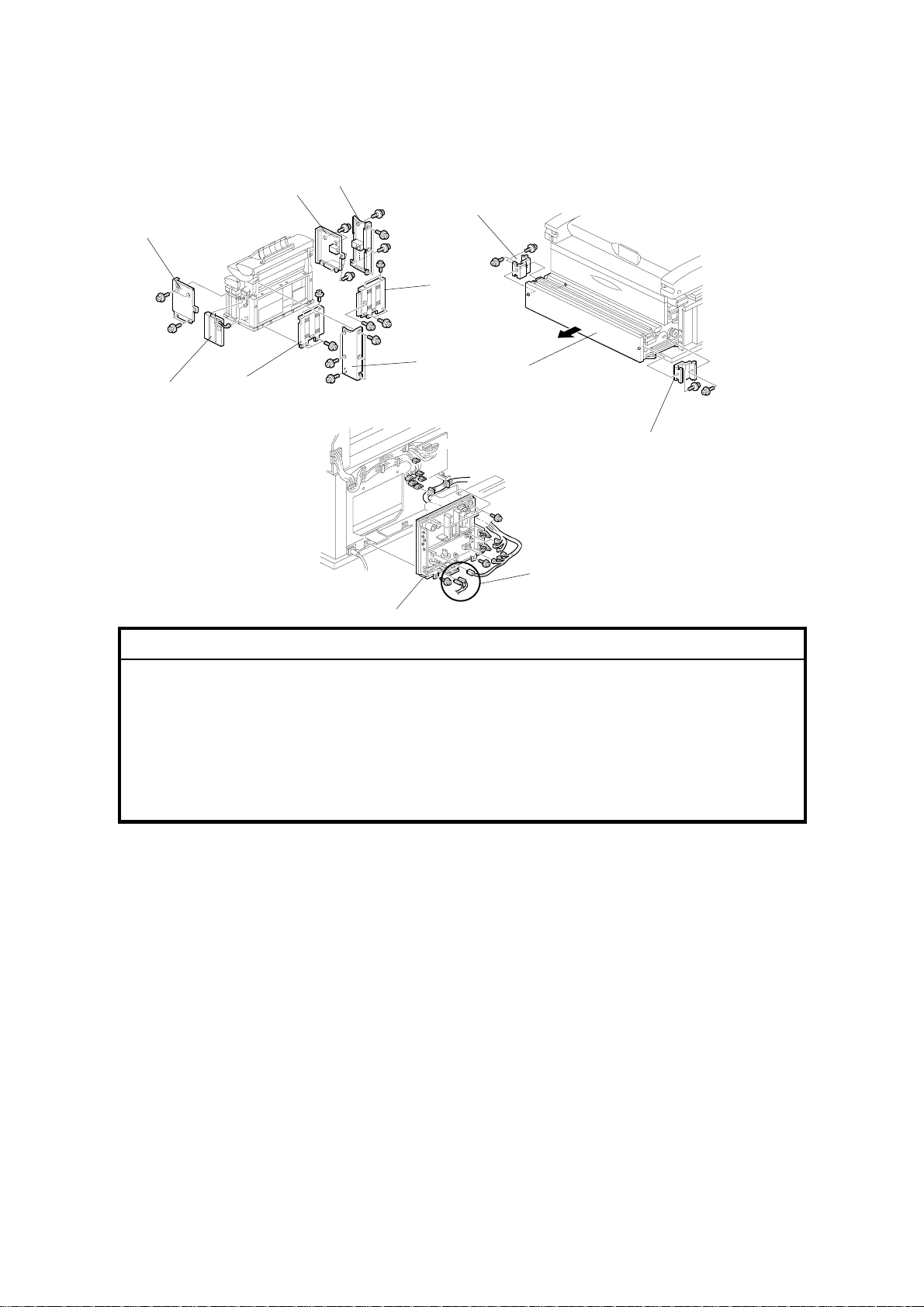
3.6.1 CUTTER UNIT
[A]: Roll tray cover (! x 2)
[B]: Loosen side plate (! x 2).
[C]: Guide plate (pressure release).
[A]: Left cutter HP switch connector
(" x 1)
[B]: Left spring, hook (! x 1)
[C]: Side plate (! x 2)
[D]: Right cutter HP switch connector
(" x 1)
[E]: Cutter motor connector (" x 1,
clamps x 2)
[F]: Cutter unit (! x 2). (Slide out to
the left.)
[A]
[C]
[B]
[C]
[B]
[E]
B010R708.WMF
[A]
[F]
[D]
Adjustment
Replacement
3-17
B010R709.WMF
Page 56

PAPER FEED 25 May, 2001
3.6.2 CUTTING SENSOR AND FEED EXIT ROLLER
[A]: Lock plate (! x 2)
[B]: Sensor bracket
[C]: Cutting sensor (" x 1, ! x 1)
[B]
[E]
[C]
B010R715.WMF
[A]
Left inner cover. (☛3.6.3)
Right inner cover. (Raise out of position
without disconnecting cable.) (☛3.6.3)
[D]: Bushings (# x 2)
[E]: Guide plate (! x 4)
[F]: Feed exit roller
NOTE: Re-install the left end first
(viewed from the front.)
[F]
[D]
B010R714.WMF
3-18
Page 57

25 May, 2001 PAPER FEED
3.6.3 ROLL TRAY
!
CAUTION
The roll tray weighs 36 kg (80 lb.) At least two technicians are needed to
remove it and re-install lit.
Before removing the roll tray, prepare a clean flat surface to set the unit on after
removal. As the paper feed motor is mounted under the roll tray, a strong table, or
four blocks, to raise the roll tray slightly, is ideal and will make it easier to service.
[B]
[C]
Right covers (☛ 3.2.1)
[A]: Rear right cover (! x 5)
[B]: Open the harness clamps x 3
[C]: Connectors (" x 2)
[D]: PSU (☛ 3.9.1)
[A]: Left inner cover (! x 3)
[B]: Right inner cover (! x 2)
[C]: Harness clamp at the corner of the
right inner cover.
[A]
[A]
[D]
B010R551.WMF
[B]
Adjustment
Replacement
3-19
[C]
B010R707.WMF
Page 58

PAPER FEED 25 May, 2001
[A]: Harness clamps inside the machine (x
2)
B010I513.WMF
[A]
[A]: Roll tray (! x 4 with washers)
Do not remove the stainless steel
spotting screws on either side of the roll
tray.
[B]: Pull the connector from the back to the
front of the machine. Coil it and then
[A]
place it inside the roll tray.
With a technician on either side of the
roll tray, lift it off the rail and set it down
on a clean flat surface. The roll tray
B010R711.WMF
weighs about 32 kg (70.5 lb.)
[B]
3-20
Page 59

25 May, 2001 PAPER FEED
3.6.4 PAPER FEED DRIVE MOTOR
The paper feed drive motor is located under the front left corner of the roll tray.
Roll tray
Left inner cover (! x 3)
[A]: Paper feed drive cover, left rear
corner (! x 1)
[B]: Loosen adjustment screw.
[C]: Remove pressure spring
[D]: Motor assembly (" x 1, ! x 2
top, ! x 2 side)
[E]: Paper feed motor (! x 2)
[C]
3.6.5 FIRST FEED ROLLER AND CLUTCH
Roll tray
[A]: Bushings (# x 2)
[B]: First feed roller ($ x 1)
[C]: Paper feed clutch (" x 1, clamps x
2)
[B]
[E]
[B]
[A]
[D]
B010R712.WMF
[C]
Adjustment
Replacement
Adjustment Required After
Replacement
Adjust the cut length.
SP1920-001 ~
081
SP1921-001 ~
025
Cut Length Adjustment
Cut Length Adjustment
[A]
[A]
B010R716.WMF
3-21
Page 60

PAPER FEED 25 May, 2001
3.6.6 SECOND FEED ROLLER AND CLUTCH
[C]
Roll tray
[A]: Bushings (# x 2)
[B]: Second feed roller ($ x 1)
[C]: Paper feed clutch (" x 1, clamps x
2)
Adjustment Required After
Replacement
Adjust the cut length.
[A]
[B]
[A]
SP1920-001 ~
081
SP1921-001 ~
025
Cut Length Adjustment
Cut Length Adjustment
3.6.7 REGISTRATION MOTOR
Main machine left covers (☛ 3.2.1)
Top cover plate (! x 1)
[A]: Open clamps
[B]: Registration motor bracket (" x 3, !
x 3)
[C]: Registration motor (! x 4)
B010R713.WMF
[B]
[C]
3-22
[A]
B010R915.WMF
Page 61

25 May, 2001 PAPER FEED
3.6.8 REGISTRATION CLUTCH
Registration motor (☛ 3.6.7)
[A]: Stopper bracket (! x 1)
[B]: Registration clutch
NOTE: Use the flat head of a small
screwdriver to release the lock on
the clutch.
[A]
3.6.9 REGISTRATION ROLLER
Left and right covers, By-pass feed table (☛ 3.2.1)
Registration motor (☛ 3.6.7)
Registration clutch (☛ 3.6.8)
[A]: Cover plate (! x 2)
[B]: T&S power pack (! x 2, " x 1)
[C]: Torque limiter bracket (! x 2)
[D]: Torque limiter (! x 1)
[A]: Guide plate (! x 4)
[B]: Aluminum guide plate (! x 4)
NOTE: Hold the plate level as you pull it
out so the plastic flaps do not fall
from either end.
[C]: Registration roller (# x 2, bushings x
2)
[B]
[C]
B010R904.WMF
[C]
B010R910.WMF
[B]
[D]
[A]
Adjustment
Replacement
3-23
[A]
[B]
B010R905.WMF
Page 62

TRANSFER UNIT 25 May, 2001
3.7 TRANSFER UNIT
3.7.1 TRANSFER AND SEPARATION CORONA WIRES
Left, right upper unit covers (☛ 3.2.1)
Left inner cover plate (☛ 3.2.1)
Right inner cover plate (☛ 3.2.1)
[A]
[A]: Loosen (do not remove) (! x 2)
[B]: T&S corona unit connectors ("
x2)
[C]: T&S corona unit. (Press down on
the covers on both ends to prevent
them from falling.)
CAUTION: Remove the T&S corona unit
carefully to avoid touching or scratching
the OPC drum above.
[D]: Paper Guide
[A]: End block covers
[B]: Insulator plates (x 4)
[C]: Transfer and separation wires
NOTE: The single wire at the front and
double wire at the back are both
spring loaded on the left.
[A]
[C]
[D]
[C]
[A]
[B]
B010R702.WMF
[B]
[C]
When replacing wires:
• Make sure the wires are correctly
B010R703.WMF
positioned in the correct slots and not crossed.
• If replacing wires, hold them by the ends. Oil from hands could cause uneven
charge on the drum.
• Handle wires carefully. Never bend or stretch them.
3-24
Page 63

25 May, 2001 TRANSFER UNIT
3.7.2 TRANSPORT UNIT
Drum drive motor (☛ 3.5.5)
Fusing drive motor (☛ 3.8.10)
Fusing unit (☛ 3.8.1)
[A]: Duct vent (! x 2)
[B]: Internal duct. Push left and then right
to disconnect.
[C]: Transport unit (! x 4, " x 2)
[A]
!
CAUTION
When disconnecting the connectors
from the transport unit, avoid
touching or hitting the sharp
stripping pawls above the transport
unit.
[B]
[C]
B010R704.WMF
Adjustment
Replacement
3-25
Page 64

TRANSFER UNIT 25 May, 2001
3.7.3 TRANSPORT BELTS
[A]: Guide plate (! x 2)
[B]: Left transport fan motor (! x 2)
[C]: Right transport fan motor (! x 2)
[A]: Arm bushings (! x 3)
[B]: Bracket (! x 1)
[C]: Bushings x 2
[D]: Drive gear
[E]: Drive shaft
[F]: Transport belts
[B]
[E]
[C]
[D]
[A]
B010R705.WMF
[C]
[B]
[C]
[F]
B010R706.WMF
[A]
3-26
Page 65

25 May, 2001 FUSING SECTION
3.8 FUSING SECTION
3.8.1 FUSING UNIT
!
CAUTION
To avoid serious personal injury, before removing the fusing unit, switch
off the main power, unplug the machine from its power source, and allow
the fusing unit to cool.
[A]: Fusing lower cover (! x 2)
[B]: Connector (" x 1)
[C]: Grounding wire (! x 1)
[D]: Paper exit cover (hinges x 2)
[A]: Grounding wire (! x1)
[B]: Paper exit guide plate (hinges x 2)
[B]
[A]
[D]
[A]
[C]
B010R501.WMF
Replacement
[D]
Adjustment
3-27
[B]
B010R503.WMF
Page 66

FUSING SECTION 25 May, 2001
[A]: Left connectors (" x 4)
[B]: Right connectors (" x 5)
NOTE: Mark the large bayonet
connectors before you disconnect
them so you can re-connect them in
the correct order.
[C]: Fusing unit (" x 2)
CAUTION:
• The fusing unit is heavy, about 14 kg (31
lb.) Grasp it carefully at both ends when
you remove it from the machine, and
place it on a flat clean surface.
• Re-install the fusing unit carefully to
avoid hitting the PCBs as the fusing unit
passes over them.
[A]
[B]
B010R505.WMF
[C]
3-28
Page 67

25 May, 2001 FUSING SECTION
3.8.2 PAPER JUNCTION GATE SOLENOID/EXIT SENSOR
[E]
[C]
[A]: Grounding wire (! x 1)
[B]: Spring
[B]
[C]: Solenoid arm
[D]: Guide plate (! x 4)
[E]: Solenoid (! x 2)
[F]: Exit sensor (! x 1, " x 2)
3.8.3 FPDB (FUSING PRESSURE DRIVE BOARD)
[A]: Right FPDB (" x 2, stand offs x 3)
[B]: Left FPDB (" x 2, standoffs x 3)
[F]
[D]
B010R502.WMF
[A]
Adjustment
Replacement
[A]
[B]
3.8.4 HOT ROLLER STRIPPERS/PRESSURE MOTORS
Hot roller strippers
[A]: Hot roller stripper bracket (! x 4)
[B]: Hot roller strippers
Right motor
[C]: Pressure spring
[D]: Pressure motor/bracket assembly (!
x 2)
[E]: Pressure motor (! x 2, " x 1)
Left motor
Repeat [C], [D], [E] for the left motor.
[A]
[B]
[C]
[E]
B010R504.WMF
[D]
B010R506.WMF
3-29
Page 68

FUSING SECTION 25 May, 2001
3.8.5 PRESSURE ROLLER THERMISTOR
[A]: Thermistor bracket (! x 1)
[B]: Open clamp
[C]: Thermistor
[C]
[B]
[A]
B010R507.WMF
3.8.6 THERMOFUSE/HOT ROLLER THERMISTOR
[C]
[A]: Thermofuse bracket (! x 1)
[B]: Thermofuse (! x 2)
[C]: Thermistor (! x1, " x1)
[B]
3.8.7 FUSING CLEANING ROLLER
[A]: Cleaning roller assembly (! x 4)
[B]: Bushings (! x 2)
[C]: Fusing cleaning roller
[A]
[A]
B010R508.WMF
[B]
[C]
[B]
3-30
B010R509.WMF
Page 69

25 May, 2001 FUSING SECTION
3.8.8 FUSING LAMPS
Cleaning roller assembly (☛3.8.7)
Left end of fusing lamp
[A]: Fusing lamp harness (! x 2)
[B]: Fusing lamp cover (! x 2)
[C]: Left fusing lamp bracket (! x 1)
Rotate the rubber cushions until
the cutout faces down, then
remove the harnesses from the
bracket.
Right end of fusing lamp
[A]: Open clamps x 4
[B]: Fusing lamp cover (! x 1)
[C]: Fusing lamp bracket (! x 1)
[D]: Turn the rubber cushion until the
cutout faces down, then remove
the harnesses from the bracket.
[E]: Fusing lamps
NOTE: After the lamps are re-
installed, make sure that the
rubber cushions are rotated
so the slits are facing up to
prevent the lamps from slipping out.
[B]
[C]
B010R511.WMF
[A]
[D]
[E]
B010R510.WMF
[B]
[C]
[A]
Adjustment
Replacement
3-31
Page 70

FUSING SECTION 25 May, 2001
3.8.9 HOT ROLLER AND PRESSURE ROLLER
Fusing lamps (☛ 3.8.8)
[A]: Wire clamp
[B]: Gear
[C]: Hot roller bushings
[D]: Hot roller
Fusing cleaning roller (☛ 3.8.7)
Hot roller strippers (☛ 3.8.5)
[A]: Fusing entrance guide (! x 1)
[B]: Pressure plate (! x 1)
[C]: Bushings
[D]: Pressure roller
[C]
[C]
[B]
[D]
[A]
B010R512.WMF
[B]
[C]
[A]
3-32
[C]
[D]
B010R513.WMF
Page 71

25 May, 2001 FUSING SECTION
After Replacing Hot Roller or
Pressure Roller
Rough Adjustment
1. Execute SP1914 001 (set to On) to
ensure that the pressure motors [A]
are at the home position.
2. Measure the length of the spring [B]
with calipers.
Correct spring length:
Outside
28.8± 0.3 mm
3. If the spring length is longer or
shorter than the correct
measurement, adjust the position of
the home position sensor [C].
Move sensor: To make the spring:
Toward the motor Longer
Away from the motor Shorter
[A]
[C]
[B]
B010R917.WMF
Adjustment
Replacement
4. Measure the spring length again with calipers to confirm that it is correct.
Fine Adjustment
During normal operation the spring, bracket, and sensor move out of the home
position to the correct position determined by automatic software calculations for
the paper type, fusing mode setting, and fusing roller temperature.
The following SP codes can be used to select the pressure control correction
settings if skewing occurs after changing the paper length selection.
SP1914 002 Right Pressure Adjustme nt
SP1914 003 Left Pressure Adjust me nt
Changing these SP codes does not change the position of the bracket and sensor
immediately after adjustment. The position is adjusted only during copying.
If these SP codes are adjusted, the settings must be the same size but of opposite
sign
(Example: Right Pressure +1 / Left Pressure –1)
3-33
Page 72

FUSING SECTION 25 May, 2001
3.8.10 FUSING DRIVE MOTOR
Main unit left covers (☛ 3.2)
Left inner cover (☛ 3.2)
[A]: Spring x 1
[B]: Fusing drive motor unit (! x 3,
" x 1)
[C]: Fusing drive motor (! x 4)
NOTE: When re-in stalling the
fusing drive motor, make
sure that the drive shaft is
correctly engaged with the
timing belt [D].
[B]
[C]
[A]
[D]
B010R559.WMF
3-34
Page 73

25 May, 2001 BOARDS
3.9 BOARDS
3.9.1 PSU (POWER SUPPLY UNIT)
Left covers (☛ 3.2.2)
[A]: PSU (! x 4, " x all)
NOTE:
• Before removing the Neutral and Line
bayonet connectors [B], mark them “N”
and “L” before you remove them so you
can match them with the N (left) and L
(right) notations on the board when you
re-connect them.
• If a copy tray support has been installed
below the board, you may need to
remove it in order to remove all the
screws from the PSU board.
B010R907.WMF
[A]
Adjustment
Replacement
3.9.2 IOB (INPUT OUTPUT BOARD), M CU (MAIN CONTROL UNIT)
[A]: Cables
[B]: IOB (! x 8)
[C]: MCU (! x 5)
NOTE: When replacing the MCU, always
reattach the three NVRAMs
(IC101, 108, 109) on the new
MCU.
[B]
IC101
IC108
IC109
[A]
[C]
B010R950.WMF
3-35
Page 74

BOARDS 25 May, 2001
3.9.3 IPU (IMAGE PROCESSING UNIT)
[A]
[A]: Ribbon cables
[B]: Optional stamp board (if installed)
[C]: IPU (! x 8)
[C]
3.9.4 HDD REPLACEMENT
Rear right, rear left covers (☛ 3.2.2)
[A]: HDD Unit (! x 4, " x 4)
[A]
[B]: HDD Cover (! x 4)
[C]: HDD (! x 3)
The machine cannot operate with only one
functional HDD. A defective HDD must be
installed to restore full operation .
Both disks must be the same model and
capacity.
[B]
[B]
B010R552.WMF
B010R553.WMF
[C]
Execute the following SP:
If a new HDD is not available
4960 015
After installing a new HDD, do the following in the order listed below
4960 007, 008
4960 003, 004 After installing the HDD, execute to format HD D1 (003 ) or H D D2 (00 4).
Execute to disable HDD ac cess so the customer can continue us ing the
machine.
After installing the HDD, execute to clear the bad sector count stored in
NVRAM for the old HDD1 (007) or HDD2 (008).
3-36
B010R554.WMF
Page 75

25 May, 2001 ADJUSTMENTS
3.10 ADJUSTMENTS
3.10.1 CIS AND WHITE PLATEN ROLLER ADJUSTMENT
Perform this adjustment after replacing the CIS (Contact Image Sensor) or the
white platen roller.
This adjustment achieves even image density, even if the image density of the
white platen roller is uneven. The standard original used for this adjustment is one-
sheet of plain paper (cut sheet or roll) paper with a horizontal main scan and
vertical sub scan (945 W x 210 L mm ± 5mm).
NOTE: The width of the main scan direction must be 926 mm or more.
1. On the operation panel, press ".
2. Enter #$%
3. Hold down & for more than 3 seconds.
4. On the touch panel, press Copy SP.
5. Enter 4428 002, press ' , and then press Start to execute the image scan
adjustment.
Adjustment
Replacement
6. Insert the original.
7. Enter 4428 001, press ' and then press Start to confirm that the previous SP
executed correctly.
3-37
Page 76

ADJUSTMENTS 25 May, 2001
3.10.2 LPH ADJUSTMENT
Summary
Remove the LPH, replace the three ROMs on the VDB, and then install the new
LPH. (See section 3.4.2.)
Before replacing the right copy tray, read the LPH settings from the labels attached
to the LPH.
SP2965 001 (ML) aaa SP2965 002 (MR) bbb SP2965 003 (SL) ccc SP2965 004 (SR) d
Write down the four numbers on the right side of each label (aaa, bbb, ccc, d).
These are the recommended factory setting s for each SP.
After replacing the LPH (LED Print Head) and inputting the above settings, execute
a test print in the IPU Test Pattern mode to make sure that the LPH joints are
aligned correctly.
Entering the LPH Factory Adjustments
1. Press (.
2. Enter #$% and then hold down & for over 3 seconds to enter the SP
Mode.
3. On the touch panel, press Copy SP.
4. Enter 2965 001, enter the recommended setting for the firs t SP, and then pr ess
'.
5. Enter the settings for 002, 003, and 004. (Just press to move to the next
SP.) Make sure that you press ' after you enter each setting
6. Press the Exit button, enter 2941 001, and then press '.
7. Enter 03 for IPU Test Pattern 3, press ', and press Exit. The machine is now
in the IPU Test Pattern mode.
8. At the top of the screen press Copy Mode to return to the main operation
screen.
3-38
Page 77

25 May, 2001 ADJUSTMENTS
Printing and Checking the Test Pattern
1. Feed any wide original 914 mm (36”) wide and at least 297 mm (11”) long. (A
blank sheet cut from the roll is sufficient.) After a few seconds, the IPU Test
Pattern prints.
2. Fold the printed pattern and measure 150 mm (about 6”) to the left and right
from the center fold
[A] [B]
The LPH has three sections: LPH1 on
the left, LPH2 in the center, and LPH 3
on the right. The LEDs overlap slightly
B010R563.WMF
where the segments are joined at LPH1,
LPH2 [A], and at LPH2, LPH3 [B].
If the lines are faint and appear neither
white nor black, the LPH is adjusted
correctly.
Adjustment
Replacement
If black or white lines are clearly visible
(see the diagram below), the LPH joints are
out of adjustment.
At LPH1, LPH2 [A] too many LEDs are
switched off and the result is a white line.
At LPH2, LPH3 [B], too many LEDs are
switched on, and the result is a black line.
[A] [B]
B010R561.WMF
B010R568.WMF
B010R562.WMF
3-39
Page 78

ADJUSTMENTS 25 May, 2001
3. If the left line is black, adjust SP2965 001 up, and if it is white, adjust it down.
4. If the right line is black adjust SP2965 002 up, and if it is white, adjust it down.
• Insert the wide original between each adjustment to print another pattern and
check the effect of each adjustment.
• Adjusting these SPs up in intervals of 10 (410, 420, etc.) switches off one
LED for every interval, and adjusting down 10 switches on one LED.
• Adjusting these SPs up less than 10 (411, 412, etc.) decreases the light
intensity of the LED, and adjus ting down less than 10 increases the light
intensity.
• Adjust the lines until they are faint; the lines cannot be completely erased.
5. Broken lines across the IPU Test Pattern indicate that the sub scan timing
between LPH1, and LPH2 [A], or between LPH2 and LPH3 [B] is incorrect.
[A]
6. To adjust the timing at the joints:
SP2965 003 (SL) Adjusts the timing at LPH1, LPH2 [A]
SP2965 004 (SR) Adjusts the timing at LPH2, LPH3 [B]
a) First adjust 2965 003, and make a test print.
b) If the timing at joint [A] is incorrect, adjust 2965 003 again.
c) When th e timing at joint [A] is correct, adjust 2965 004 until the timing at
joint [B] is correct.
[B]
B010R564.WMF
3-40
Page 79

25 May, 2001 ADJUSTMENTS
3.10.3 IMAGE POSITION, MAGNIFICATION, MARGIN
ADJUSTMENTS
Do these adjustments if the customer is unhappy about the above properties of the
output.
Before you do any measurements, allow the test print output to cool for three
minutes.
NOTE: Always do these adjustments in the order prescribed below.
START
↓
1 Printer: Skew Adjustment for
Long Printouts
SP1914 002, 003 (Fusing Pressure Adjustment)
Standard: No more than 1 mm skew /1 m
Difference between the two SP values must be less than 30.
2 Printer: Sub-scan
Magnification Adjustment
↓
3 Scanner Mask Setting
↓
4 Erase Margin Setting SP2101 001~003 (Printing Erase Margin: Leading, Trailing,
↓
5 Printer: Leading Edge
Registration
↓
6 Printer: Side-to-side
Registration
↓
7 Printer: Cut Length Adjustment SP1920 (Cut Length Adjustment)
↓
8 Scanner: Magnification SP4101 (Scanner Main Scan Magnification)
↓
9 Scanner: Leading Edge
Registration
↓
10 Scanner: Side-to-side
Registration
↓
11 Printer/Scanner: Trailing Edge
Registration (Synchro-cut)
↓
12 Scanner Mask Setting SP4012 (Scanner Erase Margin)
↓
13 Erase Margins SP2101 001~003 (Printing Erase Margins: Leading, Trailing,
↓
END
SP1915 001 (Magnification Adj. by Fusing Motor Speed)
Standard: Magnification error less than ±0.3%.
SP4012 (Scanner Erase Margin) → 0
Left)→ 5 mm
SP1001 (Leading Edge Registration)
Standard: 5±0.5 mm
SP1002 (Side-to-side Registration)
Standard: 5±0.5 mm
SP1921 (Cut Length Adjustment)
Standard: Depends on the length
SP4008 (Scanner Sub Scan Magnification)
Standard: Magnification error less than ±0.5%
SP4010 001 (Scanner Sub Scan Registration)
Standard: ±1.5 mm
SP4011 (Scanner Main Scan Registration)
Standard: ±1.5 mm
SP4961 (Original Adjustment)
SP4961 001 Standard: 210 mm ±0.5 mm
SP4961 002 Standard: 1000 mm ±1 mm
Return to previous setting (before step 3)
Left) → Return to previous setting (before step 3)
Adjustment
Replacement
3-41
Page 80

ADJUSTMENTS 25 May, 2001
1. Skew adjustment for long printouts
1. Set normal weight plain paper (841 mm wide/E size, from roll 1) and print an
IPU dot pattern with SP2941-1 (IPU Test Pattern – Pattern 11), of length 6 m,
and output to the rear exit.
2. At the rear paper exit, measure the amount of skew on the output. Make sure it
is within the standards below.
Allowed skew < 1 mm per meter
3. If the amount of measured shift is not within standards, adjust the right and left
fusing pressure from the pressure roller with the following SP codes.
SP1914 002 Fusing Pressure Roller Motor – Rig ht Pressure Adjustment
SP1914 003 Fusing Pressure Roller Motor – Left Pressure Adjustment
If the paper is skewed to the right, weaken the pressure on the right roller, then
increase the pressure on the left roller.
To determine if there is skew, look at the trailing edge.
The SP values must be the same size, but of opposite sign (for example, if SP
1914 002 is –10, SP 1914 003 must be + 10). The difference between the two
SP values must be less than 30.
If roller pressure adjustment is not successful, return the SP settings to their
previous values. Then do the next procedure to adjust the line speed, and then
try again to adjust roller pressure.
3-42
Page 81

25 May, 2001 ADJUSTMENTS
2. Printer sub-scan magnification adjustment
1. Set normal weight plain paper (841
mm wide/E size, from roll 1) and
print an IPU dot pattern with
SP2941-1 (IPU Test Pattern –
Pattern 11), of length 6 m, and
output to the rear exit.
One strip of
20 squares
1189 mm
2. Within one A0 length (1189 mm) of
the leading edge, measure the
lengths of six strips of 20 squares
on the test pattern, as shown on
the drawing.
Plain paper
(6 m)
3. Also, within 50 mm of the trailing
edge, measure the length of one
strip of 20 squares on the test
pattern.
500 mm
Adjustment
Replacement
B010R569.WMF
Standard
Ave. length of the 7 patterns = 108. 373 mm ±0.3%
• If the measurements are not within standard, execute SP1915-001
(Magnification Adj. by Fusing Motor Speed). Setting a larger value stretches
the image.
• If skew could not be adjusted in the previous procedure, set a smaller value
for SP1915-001 that is within the above standard.
• If horizontal lines are blurred at the trailing edge, set a smaller value for
SP1915-001 that is within the above standard.
3-43
Page 82

ADJUSTMENTS 25 May, 2001
3. To set the scanner mask for the adjustments
1. Execute SP5990 002 to print the SMC Copy List (a list of the SPs).
2. Set the following SPs to zero to make measurement easier.
SP4012-1 Scanner Erase Margin – Leading Edge
SP4012-2 Scanner Erase Margin – Trailing Edge
SP4012-3 Scanner Erase Margin – Left
SP4012-4 Scanner Erase Margin – Right
4. To set the erase margin
Set the following SPs to 5 mm to make measurement easier.
SP2101-1 Printing Erase Margin – Leading Edge
SP2101-2 Printing Erase Margin – Trailing Edge
SP2101-3 Printing Erase Margin – Left
5. To adjust leading edge registration for the printer
1. Set normal weight plain paper (841
mm wide/E size, from roll 1) and print
an IPU dot pattern with SP2941-1
(IPU Test Pattern – Pattern 11).
2. Measure the leading edge
registration.
5 ± 0.5 mm
Standard
5±0.5 mm
3. Adjust SP1001 (Leading Edge
Registration) if necessary.
6. To adjust side-to-side registration for the printer
1. Set normal weight plain paper (841
mm wide/E size, from roll 1) and print
5 ± 0.5 mm
an IPU dot pattern with SP2941-1
(IPU Test Pattern – Pattern 11).
2. Measure the side-to-side registration.
Standard
5 ± 0.5 mm
B010R565.WMF
3. Adjust SP1002 (Side-to-Side
Registration) if necessary.
B010R566.WMF
3-44
Page 83

25 May, 2001 ADJUSTMENTS
7. To adjust cut length
1. Using the Preset Cut feature, make standard cuts of plain paper for A4
sideways, A3 sideways, A1 lengthways, and A0, A sideways, B sideways, D
lengthways, and E.
2. Measure the cuts and check them against the standards in the table.
Up to 297 mm
298 - 800 mm
801 - 1189 mm
1190 - 2500 mm
2501 - 3600 mm
3601 - 6000 mm
Less than ± 2 mm
Less than ± 3 mm
Less than ± 4 mm
Less than ± 7.5 mm
Less than ± 11 mm
Less than ± 20 mm
3. If a measurement does not meet the standard, then adjust the following SPs for
each roller and paper type.
SP1920-1~81 Cut Length Adjustment
SP1921-1~25 Cut Length Adjustment
8. To adjust scanner magnification
1. Copy an OS-A-1 Test Chart with plain paper (cut sheet or roll).
2. Measure the length and width of the images on the original and the copy.
Standard
Less than ± 0.5 %
3. If the measurements do not meet the standard, adjust the following SP codes.
SP4101 Scanner Main Scan Magnification
SP4008 Scanner Sub Scan Magnification
Adjustment
Replacement
9. To adjust scanner leading edge registration
1. Copy an OS-A-1 Test Chart with plain paper (cut sheet or roll).
NOTE: Make sure that you execute the copy with manual density set at the
operation panel.
2. Measure the leading edge registration.
Standard
Within ± 1.5 mm
3. If the measurement does not meet the standard, adjust the following SP code.
SP4010 001 Scanner Sub Scan Registrati on
3-45
Page 84

ADJUSTMENTS 25 May, 2001
10. To adjust scanner side-to-side registration
1. Copy an OS-A-1 Test Chart with plain paper (cut sheet or roll).
NOTE: Make sure that you execute the copy with manual density set at the
operation panel.
2. Measure the side-to-side registration, within 50 mm from the leading edge of
the copy .
Standard
Within ±2 mm
3. If the measurement does not meet the standard, adjust the following SP code.
SP4011 Scanner Main Scan Registration
11. Printer/scanner trailing edge registration (synchro-cut)
1. Prepare two originals. One must have length 210 mm, and the other must have
length 1000 mm.
2. Make a copy of each original with plain paper in the synchro cut mode.
3. Compare the original and cut copy paper lengths.
4. If the measurements do not meet the standards (see the table below), adjust
the following SP settings.
SP4961 001
SP4961 002
Original Adjustment – Synchro Cut Adjustment 210 mm
Standard: 210 mm ±0.5 mm
Original Adjustment – Synchro Cut Adjustment 1000 mm
Standard: 1000 mm ±1 mm
12. To reset the scanner mask
Reset SP4012 001~004 (Scanner Erase Margins – Leading, Trailing, Left, Right) to
the previous settings (see the SMC list printed earlier).
13. To reset the print erase margin
Reset the print erase margins to the previous settings (see the SMC list printed
earlier).
SP2101 001 Printing Erase Margin – Leadi ng Edge
SP2101 002 Printing Erase Margin – Trailing Edge
SP2101 003 Printing Erase Margin – Left
3-46
Page 85

25 May, 2001 SERVICE CALL CONDITIONS
4. TROUBLESHOOTING
4.1 SERVICE CALL CONDITIONS
4.1.1 SUMMARY
There are 4 levels of service call conditions.
Level Definition Reset Procedure
To prevent the machine from b ei ng damaged,
A
B
C
D
the SC can only be reset by a service
representative (see the note below). The
copier cannot be operated at all.
The SC can be reset by turning the main
power switch off and on if the SC was caused
by incorrect sensor detection.
The copier can be operated as usual except
for the unit related to the service call.
The SC history is updated. The machine can
be operated as usual.
Enter SP mode, then turn the
main power switch off and on.
Turn the operation switch or main
power switch off and on.
A level B’ SC can on ly be reset by
turning the main power switch o f f
and on.
Turn the operation switch off an d
on.
The SC will not be displayed.
All that happens is that t he SC
history is updated.
Trouble-
shooting
NOTE: 1) If the problem concerns electrical circuit boards, first disconnect then
reconnect the connectors before replacing the PCBs.
2) If the problem concerns a motor lock, first check the mechanical load
before replacing motors or sensors.
3) When a Level A or B SC occurs while in an SP mode, the display does
not indicate the SC number. If this occurs, check the SC number after
leaving the SP mode. This does not apply to Level B’ codes.
4) Some of these SC codes contain more than one level (SC303-1,
SC303-2, SC303-3, etc.); however, some SCs may display a “-1” even if
there is no second or third level (-2, -3).
4-1
Page 86

SC CODE DESCRIPTIONS 25 May, 2001
4.2 SC CODE DESCRIPTIONS
SC192: AMDP download error
These SCs could occur at original scanning.
No. Meaning
SC192-1 AMDP1 program load error
SC192-2 AMDP2 program load error
SC192-3 AMDP3 program load error
SC192-4 AMDP4 program performance error
SC192-5 AMDP5 program performance error
SC192-6 AMDP6 program performance error
Definition: D
The AMDP ROM enable signal could not be detected within 8 ms after program
download to the AMDP started. Program download failed three times
consecutively.
Possible Cause
• AMDP program defective.
• IC card defective
• IPU defective
SC302: Charge Corona Output Error
Definition: D
Charge corona feedback voltage of less than 1V was detected for more than
200 s.
Possible Cause
• Charge power pack is defective.
• High voltage cable is defective.
• Poor connection of the power pack connector.
• Dirty charge corona unit caused leakage.
4-2
Page 87

25 May, 2001 SC CODE DESCRIPTIONS
SC303: Charge corona wire cleaner error
No. Definition: D Po ssibl e Cause
SC303-1 Wire cleaner motor feedback v olt age of
less than 0.1 V was detected for more
than 1s.
SC303-2 Corona wire cleaning did not compl et e
within 80 s.
SC303-3 Charge wire cleaner did not return to
the home position.
SC303-4 Cleaner does not move from the home
position.
Wire cleaner motor
connector disconnected.
Wire cleaner motor
connector disconnected.
Wire cleaner motor is
operating without a load.
Wire cleaner stops due to
an overload.
Wire cleaner motor drive
circuit malfunction.
Temporary Solution
The charge corona cleaner function should be switched off with SP2804.
SC306: Charge grid output error
Definition: D
Control PWM duty value is higher than 1% (FB less than 1V) for more than 200
ms (a grid current leak).
Possible Cause
• CBG power pack is defective.
• High voltage cable is defective.
• Poor connection of the power pack connector.
• Dirty charge corona unit causing leakage
SC330: Writing ASIC signal error
ASIC: Application Specific Integrated Circuit
Definition: D
At power on, the stamp function could not execute successfully twice.
Possible Cause
• SP5137 setting incorrect
• Stamp board defective
• Poor stamp board connection
Temporary Solution
Trouble-
shooting
Use SP5137 to switch off the stamp function.
4-3
Page 88

SC CODE DESCRIPTIONS 25 May, 2001
SC353: ID sensor malfunction
Definition: D
No. Definition Remarks
SC353-1 Vsp is 0V or more than 2.5 V
SC353-2 Vsg is 0V or more than 2.5 V
SC353-3
SC353-4 LED drive current (PWM value)
SC353-5 Vsg cannot be adjusted to 4
Edge pattern voltage (2.5 V)
cannot be detected
is over 1000 or fixed at 0.
±0.2V within 20 s.
During the copy cycle, t hese SCs are
displayed after the copy is execut ed.
This SC could occur while the ID sens or
is initializing.
Possible Cause
• ID sensor defective
• ID sensor connector defective
• IOB malfunction
• CBG power pack defective
• Dirty ID sensor
• VDB defective
• LPH defective
SC360: Hard disk connection error
Definition: D
The connection of the optional HDDs could not be confirmed.
No. Meaning
SC360-1 Hard disk 1 error
SC360-2 Hard disk 2 error
Possible Cause
• Hard disk connectors disconnected.
• Hard disk defective.
• IPU board defective
Temporary Solution
Use SP4960 015 to switch off HDD access so the customer can continue to use
the machine until a replacement HDD be c omes available.
4-4
Page 89

25 May, 2001 SC CODE DESCRIPTIONS
SC361: Hard disk read error
No. Meaning
SC360-1 Bad sectors Max.: HDD1
SC360-2 Bad sectors Max.: HDD2
SC360-3 Verifying error: HDD1
SC360-4 Verifying error: HDD2
SC360-5 Formatting error: HDD1
SC360-6 Formatting error: HDD2
SC360-7 Device error: HDD1
SC360-8 Device error: HDD2
SC360-9 Device error: HDD1
SC360-10 Device error: HDD2
Definition: D
Image data on the HDD cannot be read.
Possible Causes What Happens
Bad sectors created on the hard dis k dur ing
operation.
Bad sectors created on the hard dis k while
executing SP4960-1,-2 (HD media check).
Bad sectors created on the hard dis k while
formatting SP4960-3,-4 (HD formatting).
Bad sector information is written to NVRAM
and these bad sectors will no longer be
accessed for writing in formation to disk.
Use SP4906 003, 004 to for mat the disk
and replace bad sectors with other sectors.
The affected hard disk requires
replacement (too many bad sectors e xist
already).
Trouble-
shooting
SC362: IMAC (Image Memory Access Controller) error
No. Meaning
SC362-1 Video input error
SC362-2 Video output error
SC362-4 Mode setting error
SC362-51 DMA transfer error: HDD 1
SC362-52 DMA transfer error: HDD 2
Definition: D
At the IPU, an error was detected during data compression with the GAIMAC
ASIC or during data transfer to memory.
Possible Cause
• Software error, IPU defective. Update the firmware. If this does not solve
the problem, replace the IPU board .
4-5
Page 90

SC CODE DESCRIPTIONS 25 May, 2001
SC365: Image processing parameter error
Definition: D
An image processing data file not stored in the memory was required when
writing started due to software error.
Possible Cause
• Software error. Replace software (all three firmware modules).
SC391: Development bias error
Definition: D
A development bias feedback voltage of less than 0.25V was detected for more
than 200 ms while the PWM duty value was more than 1% (development bias
leak).
Possible Cause
• Bias power pack defective
• Bias cable defective
• Poor bias cable connection
• Bias leak
SC401: Transfer corona leak error
Definition: D
A transfer corona feedback voltage of less than 0.25V was detected for more
than 200 ms.
Possible Cause
• T&S power pack defective.
• Transfer corona cable defective.
• Poor transfer corona cable connection.
• Dirty T&S corona unit caused leak
4-6
Page 91

25 May, 2001 SC CODE DESCRIPTIONS
SC411: DC separation corona current leak
Definition: D
A dc separation feedback voltage of less than 0.5V was detected after more
than 200 ms while the PWM duty value was more than 17%.
Possible Cause
• T&S power pack defective.
• Paper separation current cable defective.
• Poor paper separation current cable connection.
SC440: Drum drive motor lock
Definition: D
The motor lock signal is on longer than 5 s while the drum drive motor is on.
Possible Cause
• Drive mechanism overload.
• Motor defective.
SC441: Development drive motor lock
Definition: D
No. Meaning
SC441-1 Development drive motor lock signal is low longer than 5 s when the
development motor stops.
SC441-2 Development drive motor lock signal is high longer than 5 s when the
development motor rotates.
Possible Cause
• Drive mechanism overload
• Motor defective
• Motor disconnected
SC506: Registration motor lock
Definition: D
The registration motor lock signal is high longer than 5 s during operation.
Possible Cause
Trouble-
shooting
• Drive mechanism overload.
• Motor defective.
4-7
Page 92

SC CODE DESCRIPTIONS 25 May, 2001
SC508: Cutter 1 home position error 1
Definition: B
Both left and right home position switches of the upper cutter were on just after
the main switch was turned on, or just after the upper feed tray was opened and
closed.
Possible Cause
• Right or left home position switch defective.
SC509: Cutter 1 home position error 2
Definition: B
No. Meaning
SC509-1
SC509-2
Left home position switch stay s on 300 ms after the cutter
starts moving from left to right.
Right home position switch stays on 300 ms after the
cutter starts moving from right to left.
Possible Cause
• Cutter motor cable disconnected
• Cutter motor overload
• Motor defective
SC510: Cutter 1 home position error 3
Definition: B
No. Meaning
SC510-1
SC510-2
Right home position sw it ch st ays off 1 s after the cutter
starts moving from left to right.
Left home position switch stay s off 1 s after the cutter
starts moving from right to left.
Possible Cause
• Cutter motor cable disconnected
• Cutter motor overload
• Motor defective
4-8
Page 93

25 May, 2001 SC CODE DESCRIPTIONS
SC511: Cutter 2 home position error 1
Definition: B
Both left and right home position switches of the lower cutter were on just after
the main switch was turned on, or just after the lower feed tray was opened and
closed.
Possible Cause
• Right or left home position switch defective.
SC512: Cutter 2 home position error 2
Definition: B
No. Meaning
SC512-1
SC512-2
Left home position switch stay s on 300 ms after the cutter
starts moving from left to right.
Right home position switch stays on 300 ms after the cutter
starts moving from right to left.
Possible Cause
• Cutter motor cable disconnected
• Cutter motor overload
• Motor defective
SC513: Cutter 2 home position error 3
Definition: B
No. Meaning
SC513-1
SC513-2
The right home position switch stays off 1 s after the cutter
starts moving from left to right.
The left home position switch stays off 1 s after the cutter
starts moving from right to left.
Possible Cause
• Cutter motor cable disconnected
• Cutter motor overload
• Motor defective
Trouble-
shooting
4-9
Page 94

SC CODE DESCRIPTIONS 25 May, 2001
SC541: Fusing thermistor open
Definition: A
The fusing temperature detected by the thermistor was below 7 °C for 10 s.
Possible Cause
• Fusing thermistor defective
• Thermistor cable disconnected
SC542: Fusing temperature warm-up error
No. Definition
After switching on the machine, or after opening and closing the
SC542-1
SC542-2
machine, during warmup t he hot roller did not attain the ready
temperature within 5 minutes.
After the ready temperature, the hot roller did not reach the target
control temperature within 5 minut es.
Possible Cause
• Fusing lamp defective
• IOB board defective
• MCU board defective
SC543: Fusing overheat error 1 (software)
Definition: A
A fusing temperature of over 215 °C (419°F) was detected for 5 s
Possible Cause
• IOB board defective
• MCU board defective
• PSU defective
SC544: Fusing overheat error 2 (hardware)
Definition: A
The BICU detects an overhead error even if the software overheat protection
does not work.
SC544-1 Latch signal remains on for 50 ms
SC544-2 Normal signal on for 1 s
Possible Cause
• IOB board defective
• MCU board defective
• PSU board defective
4-10
Page 95

25 May, 2001 SC CODE DESCRIPTIONS
SC545: Fusing lamp overheat error 3
Definition: A
After reaching the ready temperature, the hot roller does not rotate, and the
fusing lamp stays on at full power for 50 s.
Possible Cause
• Hot roller thermistor not positioned correctly
SC546: Unstable fusing temperature
Definition: A
No. Meaning Remarks
SC546-1 Fusing temperature rapidly
fluctuating.
SC546 -2 Fusing temperature fluctuating
over a long interval.
Temperature fluctuates greater
than 20°C (68°C) at 1 seco nd
intervals.
Temperature fluctuates 20°C
(68°C) more than 3 times during
60 s interval.
Possible Cause
• Poor thermistor connection
SC547: Zero-cross signal malfunction
Definition: A
No. Meaning
SC547-1 Abnormal mains frequency was detected mor e t han 10 t i mes.
SC547-2 No zero-cross signal detected for 1 second.
SC547-3
No zero-cross signal detected for 2.5 s after the main switch is turned
on.
Possible Cause
• Electrical noise on the power line.
• PSU defective.
SC549: Pressure roller thermistor abnormal
Definition: D
SC547-1
SC547-2
During fusing motor rotation, pressure ro ller t emperature detected
lower than 7°C (44.6°F) for 5 s.
Pressure roller temperature detected higher t han 235°C (455°F) for 5
s.
Trouble-
shooting
Possible Causes
• SC547-1: Thermistor disconnected or connector damaged.
• SC547-2: Thermistor shorted or connector damaged.
4-11
Page 96

SC CODE DESCRIPTIONS 25 May, 2001
SC550: Left fusing pressure motor home position error 1
Definition: D
The left pressure motor did not return to home position 9 s after the left pressure
motor started.
Possible Cause
• Motor drive mechanism overload.
• Motor defective.
• Pressure home position sensor defective.
SC551: Left fusing pressure motor home position error 2
Definition: D
The left pressure motor was still at the home pos ition 1.5 s after the start signal
turned on.
Possible Cause
• Motor drive mechanism overloaded.
• Motor defective.
• Pressure home position sensor defective or disconnected.
SC552: Right fusing pressure motor home position error 1
Definition: D
The right pressure motor did not return to home position 9 s after the right
pressure motor started.
Possible Cause
• Motor drive mechanism overloaded.
• Motor defective.
• Pressure home position sensor defective.
SC553: Right fusing pressure motor home position error 2
Definition: D
The right pressure motor was still at the home pos ition 1.5 s after the start signal
turned on.
Possible Cause
• Motor drive mechanism overloaded.
• Motor defective.
• Pressure home position sensor defective or disconnected.
4-12
Page 97

25 May, 2001 SC CODE DESCRIPTIONS
SC554: Fusing drive motor error
Definition: D
The fusing drive motor lock signal stayed on (remained HIGH) for 5 s.
Possible Cause
• Fusing motor drive mechanism overloaded.
• Motor defective.
SC600: Operation panel/MCU communication error
Definition: D
The operation panel and MCU are not communicating.
Possible Cause
• Loose harness
• MCU defective
SC601: IPU/CIS communication error
Definition: D
The IPU and CIS are not communicating.
Possible Cause
• MCU defective
• Loose harness
SC602: Communication error between IPU and HDC
Definition: D
The IPU and HDC (hard disk controlle r chip mounted on the IPU) are not
communicating.
Possible Cause
• IPU board defective
• HDC mounted on IPU incorrectly
SC603: IPU/AMDP communication error
Trouble-
shooting
Definition: D
The IPU and AMDP are not communicating after 6 AMDP data transmissions.
Possible Cause
• IPU defective.
4-13
Page 98

SC CODE DESCRIPTIONS 25 May, 2001
SC605: BICU/MCU error
Definition: D
The BICU and MCU are not communicating due to a serial data communication
error or a serial data receive buffer overflow.
Possible Cause
• MCU defective
SC951: F gate signal error
Definition: D
The paper is ejected with no image (or a partial image) because the FGATE
signal that triggers image writing failed to switch off after 60 s.
Possible Cause
• Software defective. Replace the software (all three firmware modules).
• MCU defective
• IPU defective
SC953: Scanner image setting error
Definition: D
The IPU did not issue the signal required for the scanner to start image
processing.
Possible Cause
• Software defective. Replace the software (all three firmware modules).
SC954: Printer Image Setting Error
Definition: D
The IPU did not issue the signal required to start image processing for the
printing mode.
Possible Causes
• Software defective. Replace the software (all three firmware modules).
SC955: Memory Setting Error
Definition: D
Settings required for memory to start image processing are not sent from the
IPU.
Possible Causes
• Software defective. Replace the software (all three firmware modules).
4-14
Page 99

25 May, 2001 SC CODE DESCRIPTIONS
SC964: Scanner start signal error
Definition: D
The scanner receives another start signal after scanning has already started.
Possible Cause
• Software defective. Replace the software (all three firmware modules).
SC965: Print start signal error
Definition: D
The printer received another print start signal after print job has already started.
Possible Cause
• Software defective. Replace the software (all three firmware modules).
SC980: HDD access error
Definition: D
Incorrect parameter sent to the HDC (hard disk controller chip mounted on the
IPU) from the BICU.
No. Meaning
SC980-1 IDNF error (HDD1)
SC980-2 IDNF error (HDD2)
SC980-3 ABRT error (HDD1)
SC980-4 ABRT error (HDD2)
SC980-5 Sequence error (HDD1)
SC980-6 Sequence error (HDD2)
Trouble-
shooting
Possible Causes
• Software defective. Replace the software (all three firmware modules).
• MCU defective
4-15
Page 100

SC CODE DESCRIPTIONS 25 May, 2001
SC981: HDD response error
Definition: D
No response from the hard disk within 5 s after the BICU chip on the main board
sent read/write commands to the HDD contro ller.
No. Meaning
SC981-1 Power off wait (HDD1)
SC981-2 Power off wait (HDD2)
SC981-3 DMA transfer answer wait (HDD 1)
SC981-4 DMA transfer answer wait (HDD 2)
SC981-5 Spindle motor answer wait (HDD1)
SC981-6 Spindle Motor answer wait (HD D2)
Possible Cause
• Software defective. Replace the software (all three firmware modules).
• HDD defective or poor connection due to vibration
SC982: MSU error
MSU: Memory Supercharger Unit (hard disk with hard disk controller)
Definition: D
MSU (Memory System Unit) memory configuration does not meet
specifications.
SC982-1 HDD1
SC982-2 HDD2
Possible Cause
Hard disk capacity is insufficient (does not meet specification).
SC984: IMAC initialization failure
Definition: D
A hard disk was accessed when the context table RAM of the IMAC (Image
Memory Access Controller) is initialized at the beginning of the copy cycle.
Possible Cause
• Software defective. Replace the software (all three firmware modules).
4-16
 Loading...