

Ricoh af400 Service Manual

AD3
(Machine Code: A133)

IMPORTANT SAFETY NOTICES
PREVENTION OF PHYSICAL INJURY
1. Before disassembling or assembling parts of the copier and peripherals,
make sure that the cop ier po w er cord is un pl u gg ed .
2. The wall outlet should be ne ar th e cop i er an d easily accessible.
3. Note that some compone nt s of th e cop i er an d the paper tray unit ar e
supplied with electrical voltage even if the main switch is turned off.
4. If any adjustment or operation check has to be made with exterior covers
off or open while the main switch is turned on, keep hands away from
electrified or mech anically driven components.
5. If the start key is pressed before the copier completes the warm-up period
(Start key starts blinking red and green alternatively), keep hands away
from the mechani cal an d th e el e ctr i ca l com po ne nt s as t he copie r star t s
making copies as soon as the warm-up period is completed.
6. The inside and the metal parts of the fusing uni t be com e extr e m el y ho t
while the copier is operating. Be careful to avoid touching those
components with your bare hands.
HEALTH SAFETY CONDITIONS
1. Never operate the copier without the ozone filters installed.
2. Always replace the ozone filters with the specified ones at the specified
intervals.
3. Toner and developer are non-toxic, but if you get eithe r of them in your
eyes by accident, it may cause temporary eye discomfort. Try to remove
with eye drops or flush wit h w at er as fir st aid. If unsuccessful, get m ed ical
attention.
OBSERVANCE OF ELECTRICAL SAFETY STANDARDS
1. The copier and its peripherals must be installed and maintained by a
customer service representative who has completed the training course
on those models.
CATION
2. The RAM board on the system control board has a lithium battery
which can explode if replaced incorrectly. Replace the battery only
with an identical one. The manufacturer recommends replacing
the entire RAM board. Do not recharge or burn this battery. Used
batteries must be handled in accordance with local regulations.
SAFETY AND ECOLOGICAL NOTES FOR DISPOSAL
1. Do not incinerate the toner bottle or the used toner. Toner dust may ignite
suddenly when exposed to open flame.
2. Dispose of used toner, de vel o pe r , an d or g an i c pho to con ductor according
to local regulations. (These are non-to xic supp lies. )
3. Dispose of replaced parts in accordance with local regulations.
4. When keeping used lith ium batteries in order to dispose of them later, do
not put more than 100 batteries per sealed box. Storing larger numbers or
not sealing them ap ar t ma y lead to chemical reacti o ns an d he at bui ld - up .
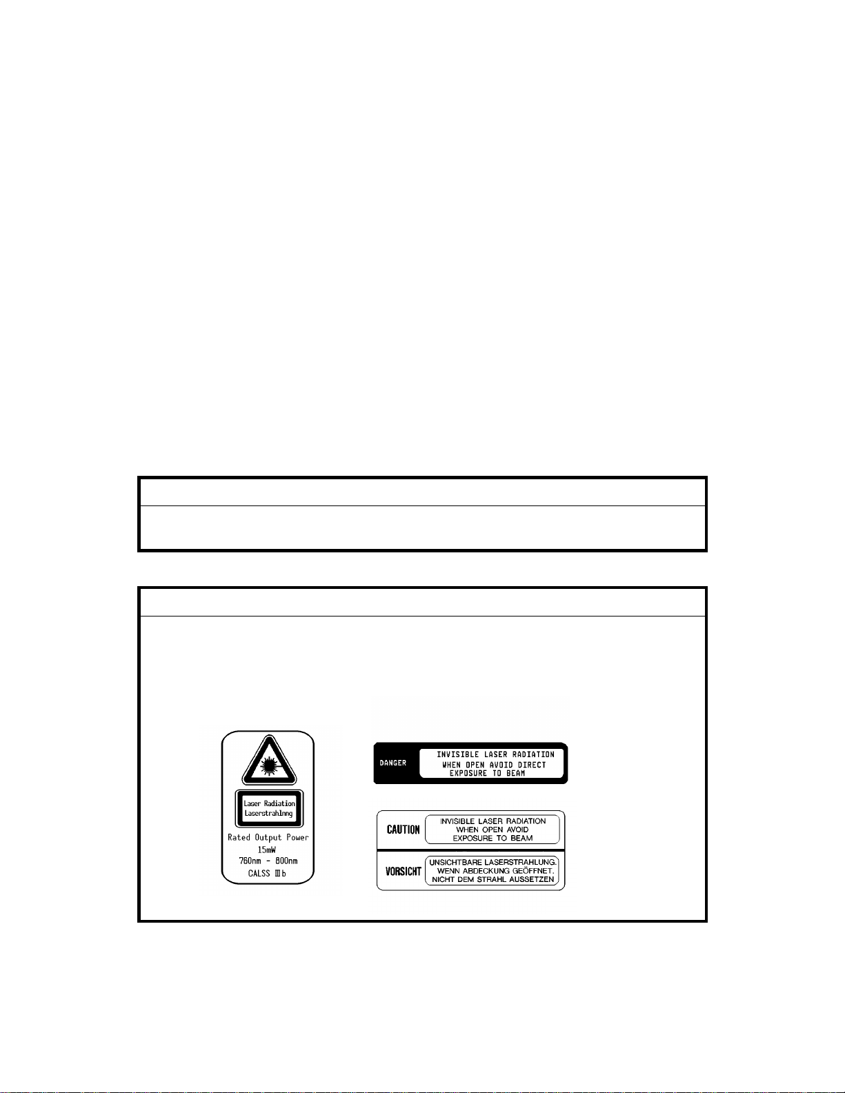
LASER SAFETY
The Center for Devices and Radiological Health (CDRH) prohibits the repair
of laser-based optical units in the field . The optical housing unit can only be
repaired in a factory or at a location with the requisite equipment. The laser
subsystem is replaceable in the field by a qualified Customer Engineer. The
laser chassis is not repairable in the field. Customer engineers are therefore
directed to return all chassis and laser subsystems to the factory or service
depot when replacement of the optical subsystem is required.
WARNING
Use of controls, or adju stm e nt, or performan ce of pr oce du r es ot he r tha n
those specified in th is manual may result in hazardous radiation exposure.
WARNING FOR LASER UNIT
WARNING: Turn off the main switch before attempting any of the
procedures in the Laser Unit section. Laser beams
can seriously damage your eyes.
CAUTION MARKING:
For 115V version
For 230V version

SECTION 1
OVERALL MACHINE
INFORMATION

22 March 1996 SPECIFICATIONS
1. SPECIFICATIONS
Configuration: Desktop
Copy Process: Dry electrostatic transfer system
Originals: Sheet/Book
Original Size: Maximum A3/11" x 17"
Copy Paper Size: Maximum
A3/11" x 17" (Paper tray)
Minimum
A5/8
A6/5
1/2
1/2
" x 5
" x 8
" sideways (Paper tray)
1/2
" lengthwise (By-pass)
1/2
LCT
A4/11" x 8
" sideways only
1/2
Duplex Copying: Maximum
A3/11" x 17"
Minimum
A5/8
1/2
" x 5
" sideways
1/2
Copy Paper Weigh t: Paper tray:
60 ~ 105 g/m2, 16 ~ 24 lb
By-pass:
60 ~ 157 g/m2, 16 ~ 42 lb
LCT:
60 ~ 128 g/m2, 16 ~ 34 lb
Duplex copying:
64 ~ 105 g/m2, 17 ~ 24 lb
Overall
Information
Reproduction R at i os: 5 Enlargement an d 7 R ed uct i on
A4/A3 Version LT/DLT Version
400%
200%
Enlargement
Full size 100% 100%
Reduction
1-1
141%
122%
115%
93%
87%
82%
71%
65%
50%
25%
400%
200%
155%
129%
121%
93%
85%
77%
74%
65%
50%
25%

SPECIFICATIONS 22 March 1996
Zoom: 25% to 400% in 1% steps
Power Source: 120V/60Hz:
More than 12 A (for North America)
220V ~ 240V/50Hz:
More than 7 A (for Europe)
220V ~ 240V/60Hz:
More than 7 A (for Asia)
Power Consumption:
Copier Only Full System
Maximum Less than 1.44 kW Less than 1.44 kW
Copying Less than 1.20 kW Less than 1.20 kW
Warm-up Less than 0.88 kW Less than 0.90 kW
Stand-by Less than 0.20 kW Less than 0.22 kW
NOTE:
1) Full System: Copier + ADF + Pap er Tr ay U nit + Fini sh er
Noise Emission:
Copier Only Full System
1. Sound Power Level
Copying 66.0 dB(A) 69.0 dB(A)
Stand-by 40.0 dB(A) 40.0 dB(A)
2. Sound Pressure Level at the Operator Position
Copying 54 dB(A) 59 dB(A)
Stand-by 25 dB(A) 25 dB(A)
NOTE:
The above measurements are to be made in accordance with ISO
7779.
Full System: Copier + ADF + Paper Tray U nit + Fini sh er .
Dimensions (W x D x H): 880 x 655 x 602 mm (34.7" x 25.8" x 23.8")
Measurement Conditions
1) With by-pass feed tab le cl ose d
2) With copy tray attached
3) With LCT cover closed
4) Without the 500-sheet copy tray
Weight: 95 kg (210 lb)
1-2

22 March 1996 SPECIFICATIONS
Copying Speed (copies/minute) :
A4 sideways/
11" x 8
"
1/2
40 18 26
Warm-Up Time
A3/11" x 17" B4/8
Less than 140 seconds (20°C, 68°F)
" x 14"
1/2
First Copy Time: Less than 5.2 s (from LCT)
Copy Number Input: Ten-key pad, 1 to 999 (count up or count down)
Manual Image Density
7 steps
Selection:
Automatic Reset: 30 s is the standard setting; it can be changed
with a UP mode.
Copy Paper Capacity:
Paper Tray By-pass Feed LCT
About 500 sheets x1 About 40 sheets About 1000 sheets
Hard Disk: 1 GB, Fast SCSI-2
Duplex Tray Capacity A4/11" x 8
": 50 sheets
1/2
A3/11" x 17": 50 sheets (80 g/m2, 20 lb paper)
30 sheets (81 ~ 105 g/m2,
21.5 ~ 27.9 lb paper)
Overall
Information
Toner Replenishment: Cartridge exchange (700 g/cartridge)
Toner Yield: 20K copies (A4, 6% full black , ID Level 4)
Optional Eq uipment:
Copy Tray Capacity B4/8
•
Platen cover
•
Document feeder
•
Paper tray unit wi th tw o pa pe r trays
•
Paper tray unit wi th thr e e pa pe r tr ays
•
Finisher
•
Key counter
•
Tray heater
•
Optical anti-condensation heater
•
Drum heater
•
500-sheet receivi ng tr ay
" x 14" ~ A4/8
1/2
" x 11" 500 sheets
1/2
A3\11" x 17" 200 sheets
Less than B5/5
1/2
" x 8
": 200 sheets
1/2
1-3
MACHINE CONFIGURATION 22 March 1996
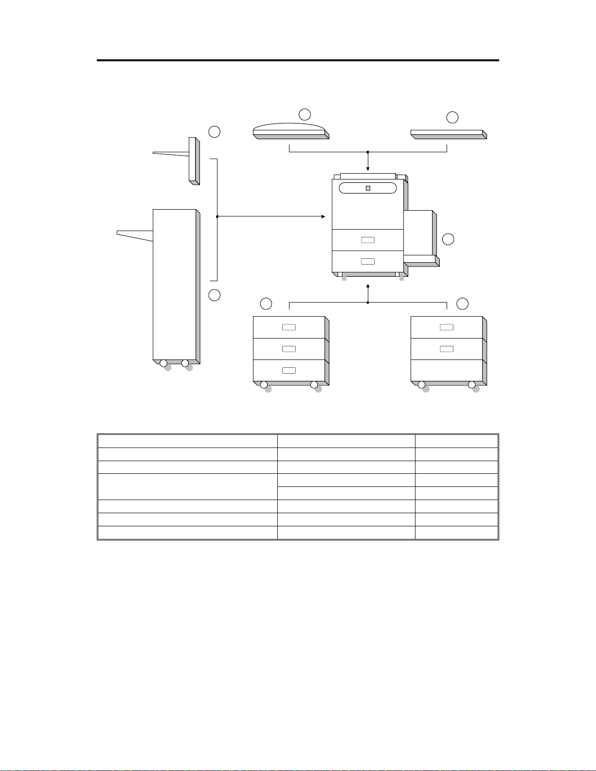
2. MACHINE CONFIGURATION
1
7
6
5 4
2
3
A133V500.wmf
Item Machine Code No.
Copier A133 3
ADF (Option) A548 1
Paper Feed Unit (Option) A549 5
A550 4
Finisher (Option) A612 6
500-sheet Receiving Tray (Option) A615 7
Platen Cover (Option) A381 2
1-4
22 March 1996 PAPER PATH
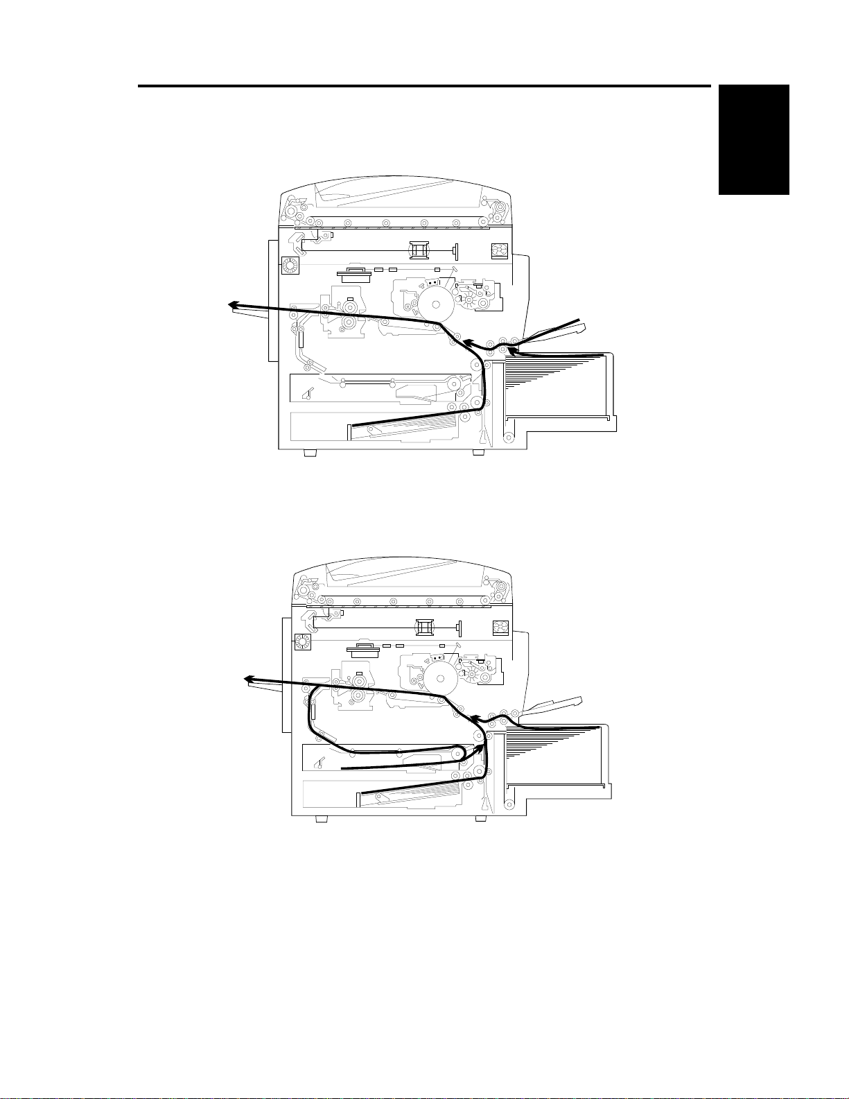
3. PAPER PATH
3.1 NORMAL COPYING
Overall
Information
3.2 DUPLEX COPYING
A133V501.wmf
A133V502.wmf
1-5
MECHANICAL COMPONENT LAYOUT 22 March 1996
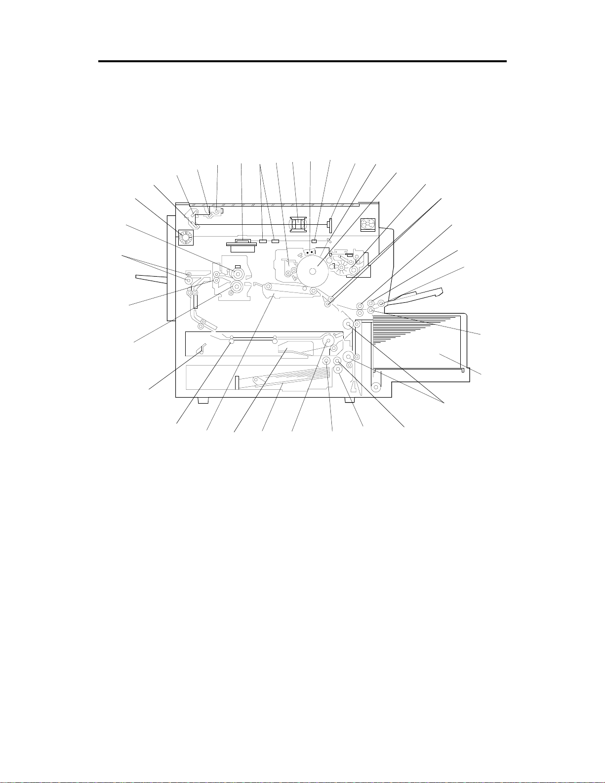
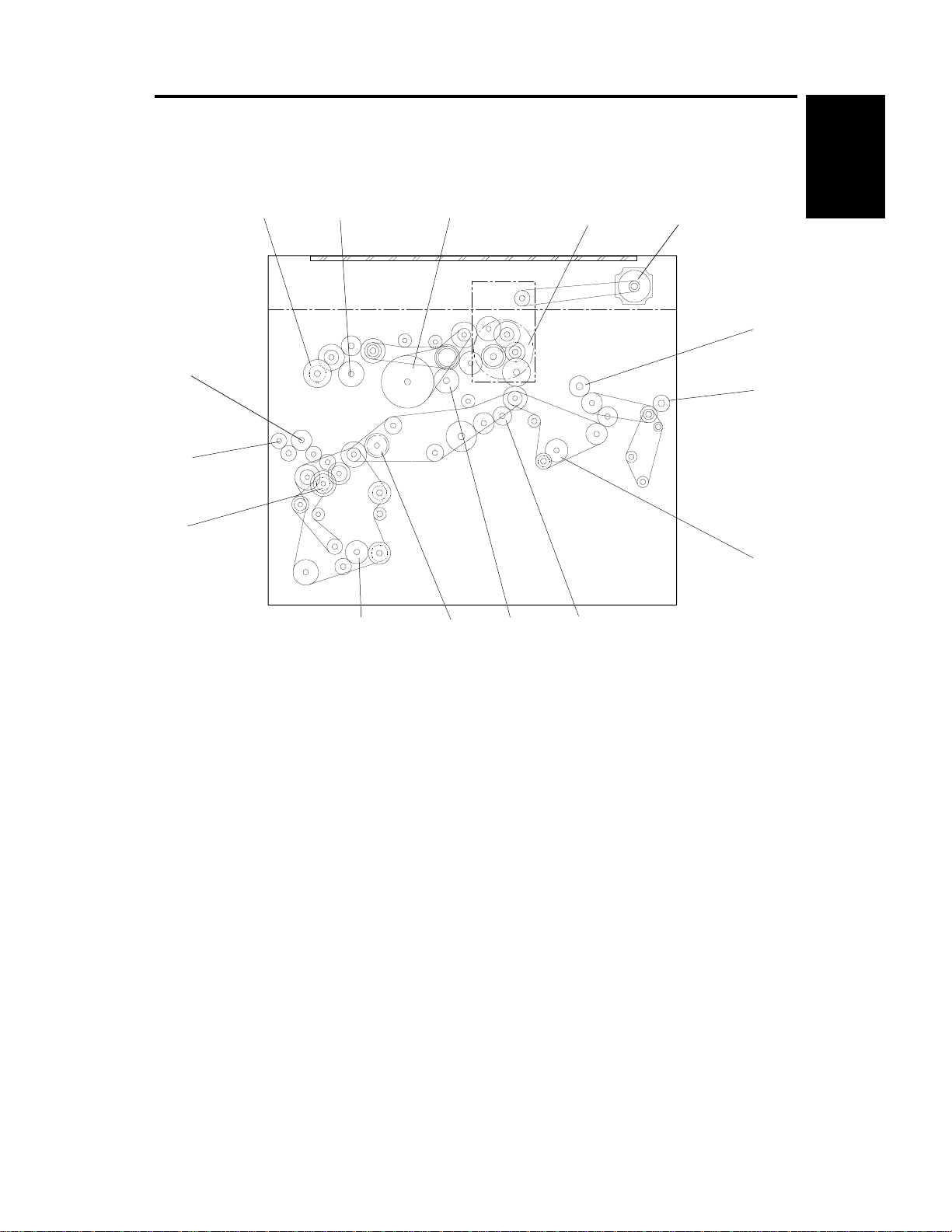
4. MECHANICAL COMPONENT LAYOUT
9
8
7
10
11
12
13
14
15
35
6
5
4
3
2
1
34
33
32
31
30
29
28
16
17
18
19
20
21
23
24252627
22
A133V503.wmf
1-6

22 March 1996 MECHANICAL COMPONENT LAYOUT
1. 3rd. Mirror
2. 2nd. Mirror
3. 1st. Mirror
4. Exposure Lamp
5. Polygonal Mirror Motor
6. Fθ Lenses
7. Cleaning Unit
8. Lens
9. Charge Corona Unit
10. Barrel Toroidal Lens (BTL)
11. CCD
12. Mirror
13. Drum
22. Feed Roller
23. Separation Roller
24. Pick-up Roller
25. Duplex Feed Roller
26. Bottom Plate
27. Side Jogger Fen ce
28. Transfer Belt Unit
29. Entrance Rollers
30. End Jogger Fence
31. Pressure Roller
32. Fusing Exit Roller
33. Exit Rollers
34. Hot Roller
Overall
Information
14. Development Unit
15. Registration Rollers
16. By-pass Feed Relay Roller
17. By-pass Feed Roller
18. By-pass Pick-up Roller
19. By-pass Separation Roller
20. LCT
21. Relay Rollers
35. Optics Exhaust Fan Motor
1-7

ELECTRICAL COMPONENT DESCRIPTIONS 22 March 1996
5. ELECTRICAL COMPONENT DESCRIPTIONS
Refer to the electrical component layout and the point-to-point diagram on the
waterproof paper in the pocket for the locations of these components.
Symbol Index
No.
Printed Circuit Boards
PCB1 90
PCB2 89
PCB3 92 DC Power Supply Provides dc power.
PCB4 93 BCU Controls the mechanical parts of the printer.
PCB5 80
PCB6 85
PCB7 87
PCB8 79 Scanner Drive Drives the scanner motor.
PCB9 81
PCB10 84
PCB11 94 Lamp Stabilizer Provides dc power for the exposure lamp.
PCB12 86
PCB13 83
PCB14 31
PCB15 33
PCB16 40 Duplex Control Controls the operation of the duplex tray.
PCB17 N/A
PCB18 51
PCB19 91
PCB20 7
Description Note
SCU Controls all copier functions both directly or
through other control boards.
AC Drive Provides ac power to the exposure lamp and
fusing lamps.
Charge High Voltage
Supply
High Voltage Control Controls the high voltage boards and the
Operation Panel Controls the touch panel display and LED
EX-IPU Processes the video signal from the SBU
SBU Contains the CCD, and outputs a video
Main Scan
Synchronization
Detector - 1
Main Scan
Synchronization
Detector - 2
Transfer High
Voltage
Development Bias
Power Pack
Liquid Crystal Display Controls the guidance display and displays
LCT Interface Interfaces the LCT control signal between
Relay Board Switches ac power to either the dc drive
Laser Diode Drive Controls the laser diode.
Supplies high voltage to the charge corona
unit.
quenching lamp.
matrix, and monitors the key matrix.
and sends the video signal to the LD unit.
signal to the EX-IPU board.
Detects the laser beam at the start of the
main scan.
Detects the laser beam at the end of the
main scan.
Supplies high voltage to the transfer belt.
Supplies high voltage to the development
roller.
guidance for machine operation.
the main board and the LCT.
board (if the main switch is on) or to the
heaters (if the main switch is off).
Motors
M1 57 Main Drives the main body components.
M2 66
Toner Bottle Drive Rotates the toner bottle to supply toner to
the toner supply unit.
1-8

22 March 1996 ELECTRICAL COMPONENT DESCRIPTIONS
Symbol Index
No.
M3 73
M4 56 Polygonal Mirror Turns the polygonal mirror.
M5 48 LCT Lift Lifts up and lowers the LCT bottom plate.
M6 74 Optics Exhaust Fan Removes heat from the optics unit.
M7 65 IPU Fan Removes heat from the IPU board.
M8 78 Exhaust Fan Removes heat from around the fusing unit.
M9 60
M10 55
M11 36
M12 39
M13 38
M14 75
M15 68
Sensors
S1 13
S2 15
S3 18
S4 46
S5 16
S6 47 Lower Relay Detects misfeeds.
S7 49
S8 50
S9 12
S10 19
S11 29
S12 30
Description Note
Tray Lift Raises the bottom plate in the paper tray.
Ozone Fan Removes ozone-laden air from inside the
machine.
Scanner Drive Drives the 1st and 2nd scanners (dc stepper
motor).
Duplex Feed Drives the feed roller and moves the bottom
plate up and down.
End Fence Jogger Drives the end fence jogger to square the
paper stack.
Side Fence Jogger Drives the side fence jogger to square the
paper stack.
DC Drive Board Fan Removes heat from around the DC drive
board.
Charge Inlet Fan Provides air flow around the charge corona
unit section.
By-pass Feed Paper
Width
By-pass Feed Paper
End
Tray Paper End Informs the CPU when the paper tray runs
Upper Relay Detects the leading edge of paper from the
Tray Upper Limit Detects the height of the paper stack in the
LCT Lower Limit Sends a signal to the CPU to stop lowering
LCT Paper End Informs the CPU when the LCT runs out of
LCT Upper Limit Signals the CPU to stop lifting the LCT
Registration Detects the leading edge of the copy paper
Image Density
(ID)
Toner Density
(TD)
Informs the CPU what width paper is in the
by-pass feed table.
Informs the CPU that there is no paper in the
by-pass tray.
out of paper.
paper tray and duplex unit to determine the
stop timing of the paper feed clutch and
duplex feed motor. Also detects misfeeds.
paper tray to stop the upper tray lift motor.
the LCT bottom plate.
paper.
bottom plate.
to determine the stop timing of the paper
feed clutch, and detects misfeeds.
Detects the density of various patterns on
the drum during process control.
Detects the amount of toner inside the
development unit.
Overall
Information
1-9

ELECTRICAL COMPONENT DESCRIPTIONS 22 March 1996
Symbol Index
No.
S13 1
S14 8
S15 9
S16 24 Fusing Exit Detects misfeeds.
S17 6
S18 32
S19 28
S20 10
S21 2
S22 34 Duplex Paper End Detects paper in the duplex tray.
S23 35
S24 42 Duplex Entrance Detects misfeeds.
S25 37
S26 41
S27 23
S28 14 By-pass Relay Detects misfeeds.
Switches
SW1 11
SW2 53
SW3 20
SW4 54
SW5 52 LCT Cover Cuts the dc power line of the LCT lift motor.
SW6 27 Main Supplies power to the copier.
SW7 26
Magnetic Clutches
CL1 61
CL2 59 Development Drives the development roller.
Description Note
Scanner HP Informs the CPU when the 1st and 2nd
scanners are at the home position.
Original Length-1 Detects the length of the original. This is one
of the APS (Auto Paper Select) sensors.
Original Length-2 Detects the length of the original. This is one
of the APS (Auto Paper Select) sensors.
Platen Cover Informs the CPU whether the platen cover is
up or down (related to APS/ARE functions).
ARE: Auto Reduce and Enlarge
Toner End Instructs the CPU to add toner to the toner
supply unit, and detects toner end conditions.
Auto Response Returns the operation panel display and exits
from the energy saver mode.
Transfer Belt
Position
Original Width Detects the width of the original. This is one
Duplex Turn Detects the trailing edge of the copy paper to
Side Fence Jogger
HP
End Fence Jogger
HP
Toner Overflow Detects when the used toner collection bottle
By-pass Feed Table Detects whether the by-pass feed table is
Tray Down Sends a signal to the CPU to lower the LCT
Tray Paper Size Determines what size of paper is in the
LCT Cuts the dc power line and detects whether
Front Cover Safety Cuts the dc power line and detects whether
Toner Supply Turns the toner supply roller to supply toner
Informs the CPU of the current position of
the transfer belt unit.
of the APS (Auto Paper Select) sensors.
determine the jogging timing, and detects
misfeeds.
Detects the home position of the duplex side
fence jogger.
Detects the home position of the duplex end
fence jogger.
is full.
open or closed.
bottom plate.
paper tray.
the LCT is open or not.
the front cover is open or not.
to the development unit.
1-10

22 March 1996 ELECTRICAL COMPONENT DESCRIPTIONS
Symbol Index
No.
CL3 76
CL4 58 Registration Drives the registration rollers.
CL5 63
CL6 71 Relay Drives the relay rollers.
CL7 72 Paper Feed Starts paper feed from the paper tray.
CL8 62 By-pass Relay Drives the by-pass relay rollers.
Solenoids
SOL1 67
SOL2 77
SOL3 64
SOL4 69
SOL5 70
Lamps
L1 3
L2 43 Fusing Provides heat to the hot roller.
L3 88
Description Note
Transfer Belt Lift Controls the touch and release movement of
the transfer belt unit.
By-pass Feed Starts paper feed from the by-pass feed
table or LCT.
By-pass Pick-up Drops the pick-up roller to the by-pass paper
feed position. When paper is fed from the
LCT, this solenoid assists SOL3.
Junction Gate Moves the junction gate to direct copies to
the duplex tray or to the paper exit.
LCT Pick-up Drops the pick-up roller all the way down to
the LCT paper feed position from the
by-pass paper feed position.
Pick-up Controls the up/down movement of the
pick-up roller in the paper tray.
Separation Controls the up/down movement of the
separation roller at the paper tray feed
station.
Exposure Applies high intensity light to the original for
exposure.
Quenching Neutralizes any charge remaining on the
drum surface after cleaning.
Overall
Information
Heaters
H1 21
H2 5
H3 22
Thermistors
TH1 45
Thermofuses
TF1 44
Thermoswitch
TS1 4
Drum (option) Turns on when the main switch is off to
prevent moisture from forming around the
drum.
Optics
Anti-condensation
(option)
Tray
(option)
Fusing Monitors the temperature at the central area
Fusing Provides back-up overheat protection in the
Exposure Lamp Opens the exposure lamp circuit if the 1st
Turns on when the main switch is off to
prevent moisture from forming on the optics.
Turns on when the main switch is off to keep
paper dry in the paper tray.
of the hot roller.
fusing unit.
scanner overheats.
1-11

ELECTRICAL COMPONENT DESCRIPTIONS 22 March 1996
Symbol Index
Counters
CO1 25
CO2 N/A
Others
CB1 17
HDD 82
Description Note
No.
Total Keeps track of the total number of copies
made.
Key
(option)
Circuit Breaker
(220 ~ 240V
machines only)
Hard Disk Drive Scanned image data is compressed and
Used for control of authorized use. The
copier will not operate until it is installed.
Provides back-up high current protection for
electrical components.
held here temporarily during copying; also
holds user stamp data.
1-12
22 March 1996 DRIVE LAYOUT
6. DRIVE LAYOUT
3
4
5
6
7
15
14
1
2
Overall
Information
13
12
11
1. Toner Supply Clutch
2. Development Clutch
3. Drum Drive Pulley
4. Main Motor
5. Scanner Drive Motor
6. Fusing Drive Gear
7. Exit Drive Gear
8. Toner Collection Bottle Drive Gear
A133V504.wmf
10
9
9. Transfer Belt Drive Gear
10. Cleaning Blade Drive Gear
11. Registration Clutch
12. Paper Feed Clutch
13. Relay Clutch
14. By-pass Feed Clutch
15. By-pass Relay Clutch
8
1-13

SECTION 2
DETAILED
SECTION DESCRIPTIONS
22 March 1996 COPY PROCESS
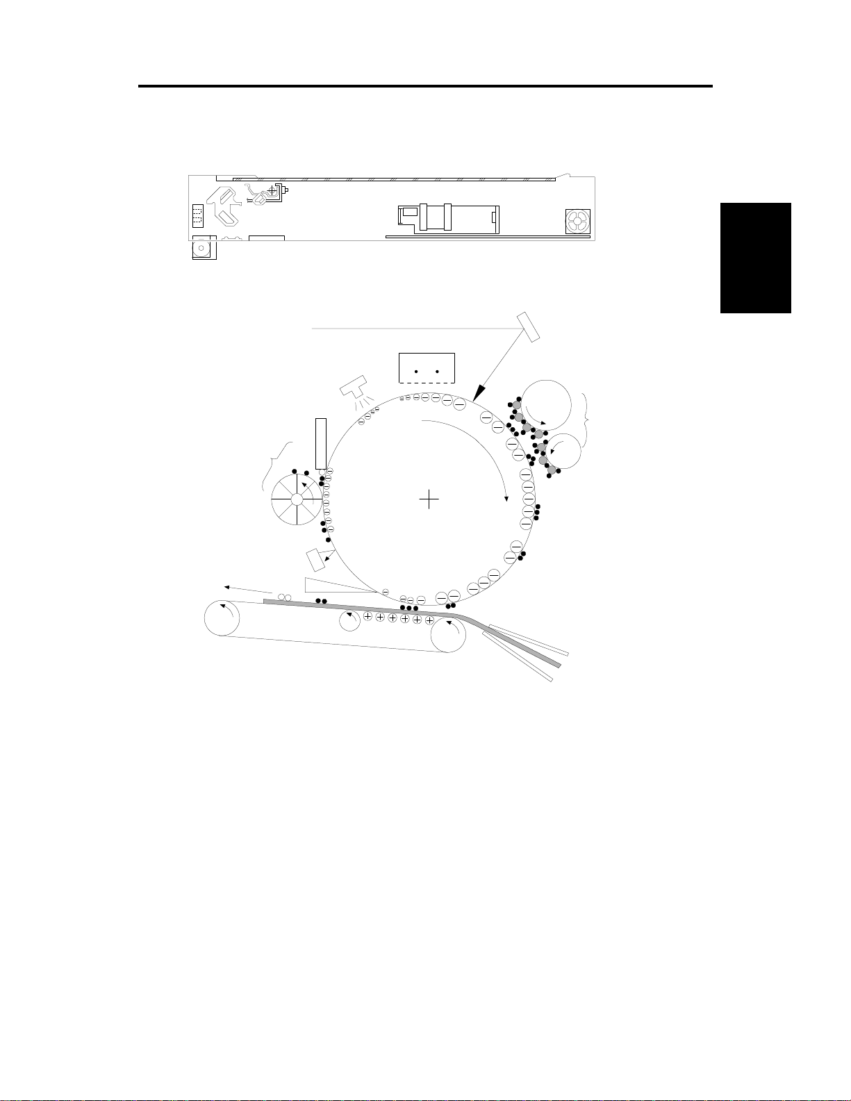
1. COPY PROCESS
1.1 OVERVIEW
1
A133D591.wmf
2
9
3
4
Detailed
Descriptions
8
7
6
5
A133D593.wmf
1. EXPOSURE
A halogen lamp exposes the original. Light reflected from the original passes
to the CCD, where it is converted into an analog data signal. This data is
converted to a digital signal, processed, and stored on the hard disk. At the
time of printi ng , th e da ta is r et r ieve d an d sent to the laser diode . For
multi-copy runs, the original is scanned once only and stored to the disk.
2. DRUM CHARGE
In the dark, the char ge cor on a un i t give s a neg at i ve cha r ge to th e or g an i c
photo-conductive (OPC) drum. The grid plate ensures that corona charge is
applied uniformly. The charge remains on the surface of the drum because
the OPC layer has a high electrical resistance in the dark.
2-1

COPY PROCESS 22 March 1996
3. LASER EXPOSURE
The processed data scanned from the original is retrieved from the disk and
transferred to the drum by a laser beam, which forms an electrical latent
image on the drum surfa c e. The am o un t of char g e r emaining as a latent
image on the drum depends on the laser beam intensity, which is controlled
by the EX-IPU board.
4. DEVELOPMENT
The magnetic develope r brush on the de vel o pm e nt roll ers come s in cont act
with the latent i m ag e on the dr um sur face. Toner particl e s ar e
electrostati call y attracted to the ar ea s of th e dr u m surfa c e whe r e th e l ase r
reduced the negative charge on the drum.
5. IMAGE TRANSFER
Paper is fed to the area between the drum surface and the transfer belt at the
proper time so as to align the copy paper and the developed image on the
drum surface. Then, the transfer bias roller applies a high positive charge to
the reverse side of paper through the transfer belt. This positive charge
produces an electr ic a l f orc e whi ch pu l l s the ton er pa r tic les from the drum
surface on to the paper. At the same time , th e pa pe r is ele c tri cally attracted
to the transfer be l t.
6. PAPER SEPARATION
Paper separates from the drum as a result of the electrical attraction between
the paper and the transfer belt. The pick-off pawls help separate the paper
from the drum .
7. ID SENSOR
On every 200th copy cycle, the laser forms a sensor pattern on the drum
surface. The ID sensor measures the reflectivity of the pattern. The output
signal is one of the factors used for toner supply control.
8. CLEANING
The cleaning brush an d cl ea ni n g blade remove any toner re m ain i ng on th e
drum surface aft er the image is transfe r red t o th e pa pe r .
9. QUENCHING
The light from the quenching lamp electrically neutralizes the charge on the
drum surface.
2-2
22 March 1996 PROCESS CONTROL
2. PROCESS CONTROL
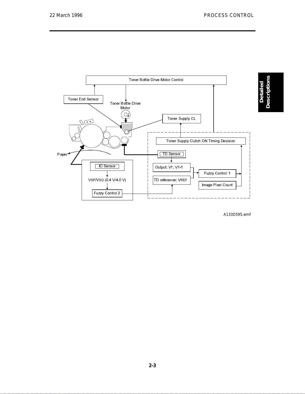
2.1 OVERVIEW
7RQHU%RWWOH'ULYH0RWRU&RQWURO
7RQHU(QG6HQVRU
3DSHU
9
6396*
)X]]\&RQWURO
7RQHU%RWWOH'ULYH
,'6HQVRU
99
0RWRU
7RQHU6XSSO\&/
7RQHU6XSSO\&OXWFK217LPLQJ'HFLVLRQ
7'6HQVRU
2XWSXW9797
)X]]\&RQWURO
7'UHIHUHQFH9
5()
,PDJH3L[HO&RXQW
A133D595.wmf
In this model, pro c ess con tr o l consi sts only of monitori n g th e to ne r den si ty
(with a correction from the ID sensor) in order to control the toner
concentration and toner supply amount.
Detailed
Descriptions
The machine controls the toner supply mechanism using readings from the
toner density sensor (TD sen s or) an d im ag e de nsity sensor (ID sensor).
Readings from the TD sensor are used to keep the toner concentration in the
developer at a constant level. However, the toner concentration on the image
on the drum varies due to variations in toner chargeability, which is
influenced by the environment and the status of the carrier, even if the toner
concentration is con sta nt. Because of this, read i ng s f rom th e ID sen sor ar e
used to change the toner concentration to kee p th e i m ag e de nsity of the
reference pattern on the drum constant.
2-3
PROCESS CONTROL 22 March 1996
2.2 TONER DENSITY CONTROL
2.2.1 Overview
There are two modes for controlling toner supply: detect supply mode and
fixed supply mode.
The mode can be changed with SP2208-1. The factory settin g is detect
supply mode.
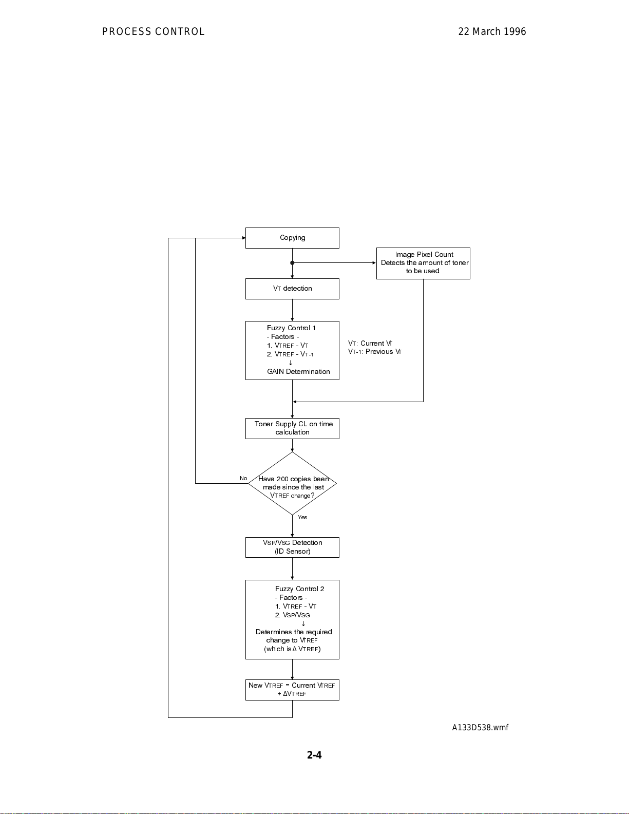
2.2.2 Detect Supply Mode Overview
&RS\LQJ
,PDJH3L[HO&RXQW
'HWHFWVWKHDPRXQWRIWRQHU
WREHXVHG
97GHWHFWLRQ
)X]]\&RQWURO
)DFWRUV
9
9
75()
75()
7
9
7
↓
9
*$,1'HWHUPLQDWLRQ
97&XUUHQW9
9
3UHYLRXV9
7
7
7
7RQHU6XSSO\&/RQWLPH
FDOFXODWLRQ
1R
+DYHFRSLHVEHHQ
PDGHVLQFHWKHODVW
9
75()FKDQJH
96396*'HWHFWLRQ
,'6HQVRU
)X]]\&RQWURO
)DFWRUV
9
75()
9639
'HWHUPLQHVWKHUHTXLUHG
FKDQJHWR9
ZKLFKLV∆9
1HZ9
&XUUHQW9
75()
∆9
75()
<HV
9
6*
↓
75()
75()
"
7
75()
2-4
A133D538.wmf
22 March 1996 PROCESS CONTROL
In detect supply mode, the machine varies toner sup ply for each copy based
on the amount of toner required to print the page (based on a black pixel
count for the page) and readings from the TD and ID sensors to maintain the
correct proportion of toner in the developer and to account for changes in
drum reflectivity over time.
The flow chart on the prev iou s pag e outl in es th e de te ct sup pl y mod e. Each
step is explained in more detail on the following pages.
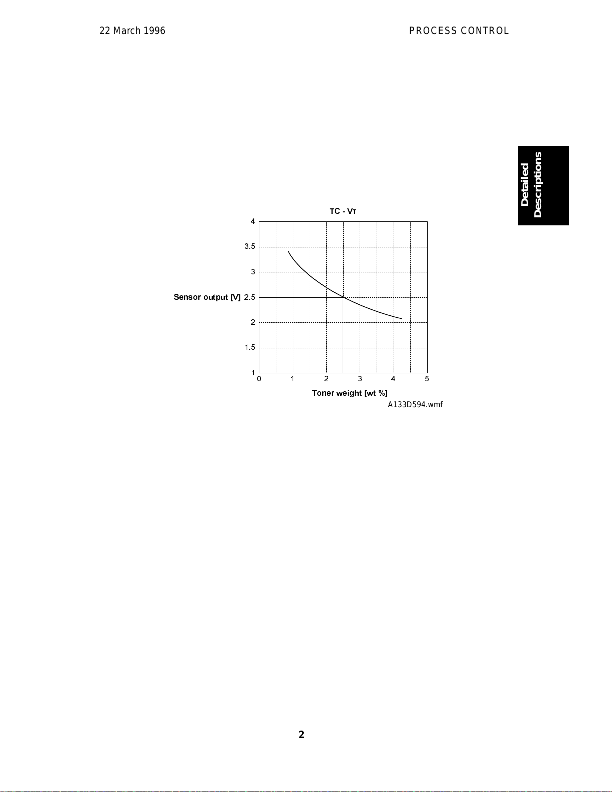
Toner Density Sensor
7&9
7
Detailed
Descriptions
6HQVRURXWSXW>9@
7RQHUZHLJKW>ZW@
A133D594.wmf
Developer consists of carrier particles (ferrite) and toner particles (resin and
pigment). Inside the de velopment unit, developer passes through a magnetic
field created by coils ins i de the toner density sen sor. When the toner
concentration changes, the voltage output by the sensor changes accordingly.
The output from th e sen s or ( VT) is checked every copy. The machine tries to
keep VT constant by varying the toner supply using a fuzzy logic process, as
shown in the flow cha rt on t he previ o us pa ge .
Toner Density Sensor Initial Setting
When new developer with the standard toner concentration (2.5% by weight,
21.25 g of toner in 850 g of developer) is installed, the TD sensor initial
setting must be done using SP mode 2801. This sets the sensor output to 2.5
± 0.1 V. This value will be used as the toner supply reference voltage (V
TREF)
of the TD sensor.
2-5
PROCESS CONTROL 22 March 1996
Toner Density Measurement
Toner density in the developer is detected on ce eve ry copy cycle. The sen sor
output voltage (VT) during the detection cycle is compared with the tone r
supply reference voltage (V
TREF).
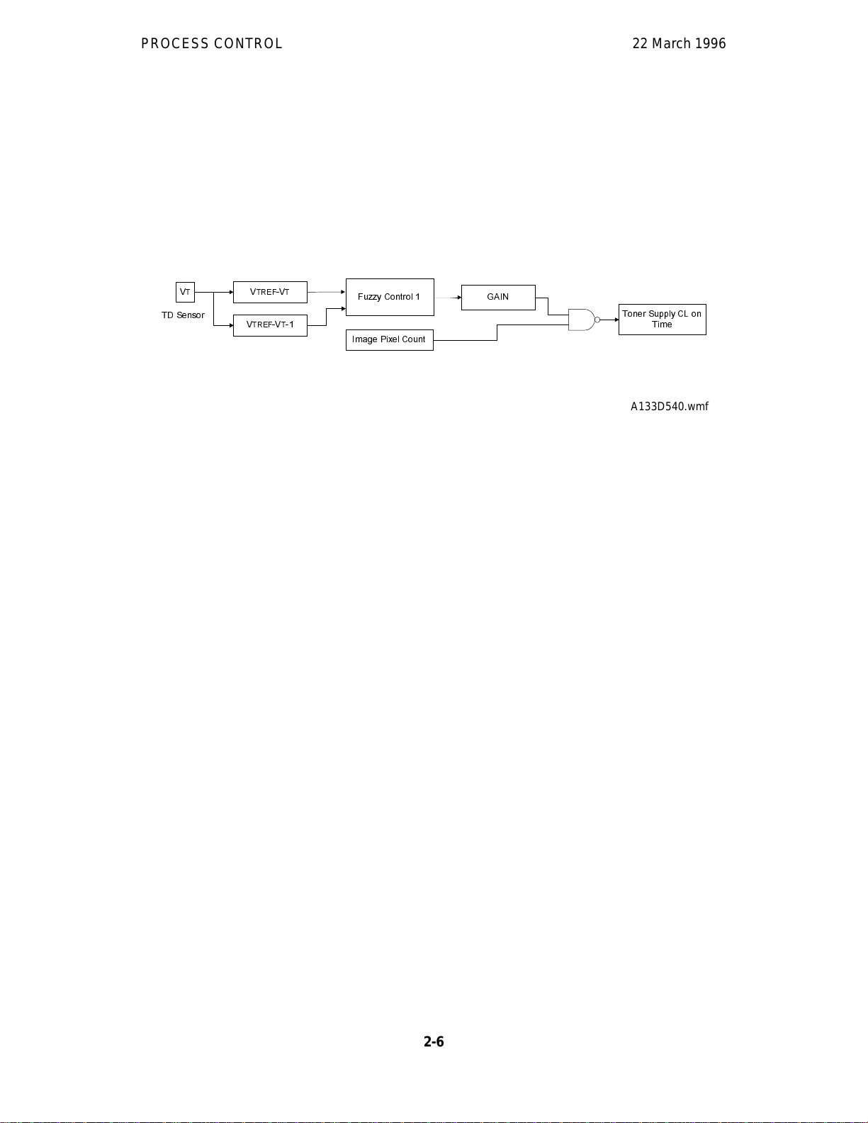
Toner Supply Clutch On Time Calculation
7
9
7'6HQVRU
75()97
9
75()97
9
)X]]\&RQWURO
,PDJH3L[HO&RXQW
*$,1
7RQHU6XSSO\&/RQ
7LPH
A133D540.wmf
- Fuzzy Control Process 1 -
To stabilize toner concentration, the toner supply amount (controlled by the
toner supply clutch on time) is determined by referring to V
TREF
and VT.
The toner supply amount is calculated every copy using the following factors.
Factor 1: V
Factor 2: V
V
•
TREF
: TD sensor output at th e latest VSP detection corrected for ID
TREF
TREF
- V
- V
T
T-1
sensor output (VSP/VSG); this is calculated every 200 copies (see
V
calibration for more details). For new developer, the TD sensor
TREF
initial setting is used.
• V
: Current TD sensor output data
T
• V
: Previous TD sensor output da ta
T-1
By referring to these factors, the machine recognizes the difference between
the current toner concentration and the target toner concentration. It then
determines the GAIN value for calculating the toner supply clutch on time.
- Image Pixel Count -
The CPU refers to the solid area ratio for the whole page informed from the
EX-IPU to improve the precision of the toner density change prediction.
The CPU converts the image data value of each pixel to the toner supply
amount. Theref or e , th e m ach i ne und ers t an ds by ho w much th e to ner supply
amount will probably change.
2-6
22 March 1996 PROCESS CONTROL
- Toner Supply Clutch On Time Calculation -
The toner supply clutch on time is decided using value of the gain which was
calculated by the fuzzy control 1 procedure , th e imag e pixel coun t valu e, the
possible amount of toner on the drum, and the toner supply rate. The
calculation is done using the following formula:
mg
2
⁄
cm
⁄
)
s
Toner supply CL on time =
GAIN x Image pixel count x 0.7
Toner supply
rate
(116
mg
NOTE: The toner supply rate can be changed with SP2209. For example, if
the user commonly makes copies with a lot of black areas, reduce
the value stored in SP2209.
V
Calibration
TREF
- VSP and VSG Detection -
The ID sensor (below the drum cleaning section) detects the following
voltages.
• V
• V
: The ID sensor output when checking the drum surface.
SG
: The ID sensor output when checking the VSP pattern.
SP
In this way, the ref lectivity of both the dru m surface and the pattern on th e
drum are checked. This compensates for any variations in the reflectivity of
the pattern on the dr um or the reflectivity of the dr um sur face.
The VSP pattern is made on t he drum by th e cha r ge cor on a un it and the laser
diode.
Detailed
Descriptions
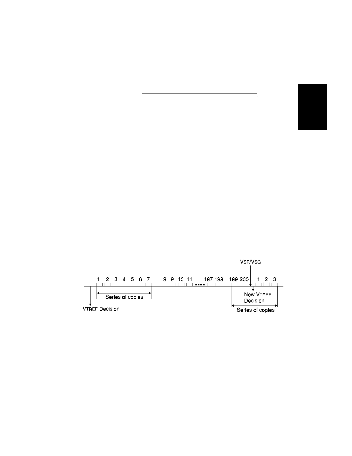
A133D541.wmf
VSP/VSG detection is performed every 200 copies to decide the new V
TREF
.
The value of the copy counter fo r the VSP/VSG detection is stored in the
NVRAM (Non-volatile RAM) on the SCU board. So, even if the machine is
switched off, the copy cou nt start s from th e nu m ber whi ch was sto r ed in the
NVRAM. In addit i on , as th e di a gr a m show s, the new V
will take effect
TREF
even if the 200th copy occurs in the middle of a copy run; however, the
overall cpm for this copy run will be lower because of the copy cycle required
to make the ID sensor pattern.
2-7
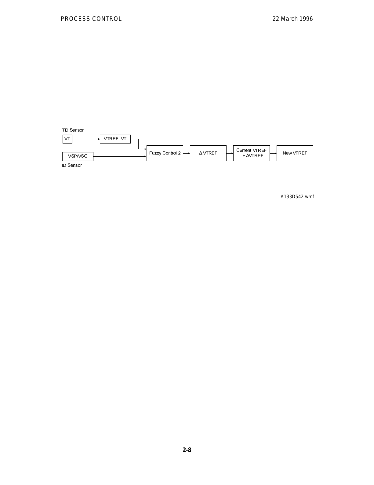
PROCESS CONTROL 22 March 1996
- New V
Determination -
TREF
Even if the toner concentration in the developer is kept constant by checking
the TD sensor, the toner potential (chargeability) and the image density
change with humidity and the amount of toner on the carrier.
Therefore, the ID sensor output is also used as one of the factors for deciding
the new V
7'6HQVRU
97
96396*
,'6HQVRU
which will be used for toner density control.
TREF
975()97
)X]]\&RQWURO
975()
∆
&XUUHQW975()
975()
∆
1HZ975()
A133D542.wmf
First of all, the CPU decides the adjustment that is required to the current
V
TREF
•
•
(∆V
V
TREF
VSP/V
) with the fuzzy control 2 procedure using the following factors.
TREF
- V
T
SG
Then, the CPU determines the new V
New V
TREF
= V
TREF
+ ∆V
TREF
From this point, toner density control is done using the new V
If V
is either higher than 4.0 V or less than 0.5 V on more than 10
TREF
using the following formula.
TREF
TREF
.
consecutive occasion s, the GAIN value is fixed at 0. 7 ( see t he equation at
the end of the "Toner Supply Clutch On Time Calculation" section). Then,
after finishing the copy job, SC390 will be generated.
2.2.3 Fixed Supply Mode
The machine supplies a fixed am o un t of ton er eve r y copy. The amo un t
depends on the settin g of SP2208-2 (for users who normally make copies
with a lot of black areas, use a higher settin g) . Re ad ing s fr om th e TD and ID
sensors are ignored.
Fixed supply mode should only be used as a temporary meas ure while
waiting for replacement parts, such as a TD sensor. The machine does not
fall back to fixed supply mode when there are sensor errors.
2-8

22 March 1996 PROCESS CONTROL
2.2.4 Toner Supply in Abnormal Sensor Conditions Overview
Under normal conditions, the machine uses detect supply mode, in which
toner supply is varied based on readings from the TD and ID sensors.
The TD sensor is checked every copy. If the readings from the TD sensor
become abnormal dur ing a copy job , th e m achi ne hold s the GAIN factor
constant (GAIN is normally calculated from TD sensor readings) to allow
toner supply to vary with only pixel count for the rest of the copy job. Then at
the end of the copy job, an SC code is generated and the machine must be
repaired. There is no fallback to fixed supply mode in this model.
The ID sensor is checked every 200 copies. If readings become abnormal,
an SC code is generate d an d th e m ach i ne must be re pa i red. If this happens
during a copy job, V
is not changed, the copy job is allowed to finish,
TREF
and then the SC code is generated.
Details of abnormal sensor detection follow below.
Abnormal TD Sensor Output (during normal operation and V
TREF
determination)
Detailed
Descriptions
When VT has been more than 4.0 V or less than 0.5 V on ten consecutive
occasions, the CPU fixes the value of the GAIN factor in th e to ne r supp ly
clutch on time formula to 0.7. Then the toner is supplied in accordance with
the value of the image pixel count data. After finishing the copy job, SC390
will be generated.
Also, SC390 is gener a te d w he n th e di f fe r en ce be tw e en VT and V
TREF
has
been more than 0.6 V ten times.
Abnormal ID Sensor Output (during VSP/V
measurement)
SG
When VSP≥2.5V or VSG≤2.5V twice consecutively, SC350 will be generated.
At this time, V
remains at the previous valu e.
TREF
Also, SC350 is gener a te d i f VSG cannot be adjusted to 4 ± 0.2V during ID
sensor initialization (SP3001: this is done after installing a new drum or a new
ID sensor, or after cleaning the ID sensor).
2-9

DRUM UNIT 22 March 1996
3. DRUM UNIT
3.1 OVERVIEW
76
1
5
4
32
The drum unit consists of the components shown in the above illustration. An
organic photoconductor (OPC) drum (diameter: 100 mm) is used in this
model.
1. OPC Drum
2. Pick-off Pawls
3. ID Sensor
4. Cleaning Brush
5. Cleaning Blade
6. Quenching Lam p
7. Charge Corona Unit
A133D500.wmf
2-10
22 March 1996 DRUM UNIT
3.2 DRIVE MECHANISM
[A]
[D]
[C]
Detailed
Descriptions
[B]
A133D501.wmf
The drive from the main motor [A] is transmitted to the drum through a series
of gears, a timing belt, the drum drive pulley [B], and the drum shaft [C] . The
main motor has a drive controller, which outputs a motor lock signal when the
rotation speed is out of the specified range.
The fly-wheel [D] on the end of the drum shaft stabilizes the rotation speed
(this prevents ba nd i ng from ap pe ar i n g an d j itter on copies).
The drum rotation speed is 150 mm/s.
2-11
DRUM UNIT 22 March 1996
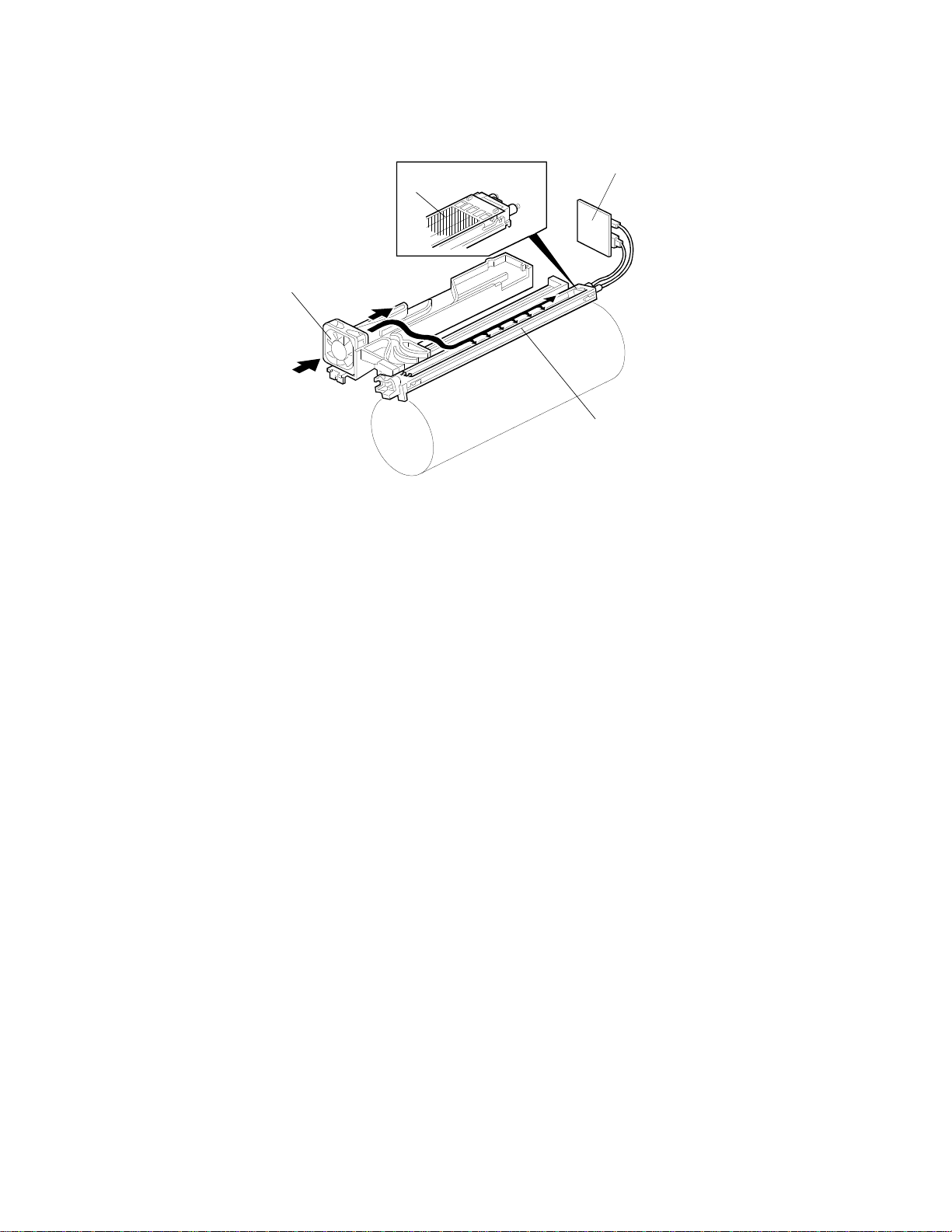
3.3 DRUM CHARGE
[B]
[A]
[C]
[D]
A133D502.wmf
This copier uses a double corona wire (single loop type) scorotron system for
charging the drum.
The two corona wires apply ne ga ti ve charg e to the dr um sur f ace . The
stainless steel grid plate [A] makes the corona charge uniform. The negative
voltage on this grid controls the amount of negative char ge on the drum.
The charge high voltage supply board [B] gives a constant corona current to
the corona wires, and applies –890V to the grid plate. The grid plate voltage
maintains a constant char ge on th e dru m surfa ce eve n w hen th e w ir e curr e nt
varies.
The ozone fan [C] provides a flow of air through the corona unit [D] in order to
prevent an uneven build up of ne ga tive io ns. This help s ma int ai n an even
image density.
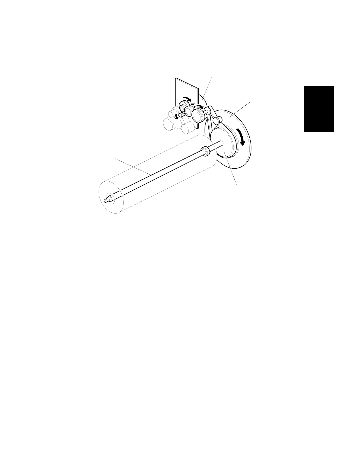
A replacement charge corona unit with wire cleaner and motor is available as
an optional service part for machines which produce a high copy volume.
2-12
 Loading...